

Page 1
STR-V5500
SERVICE MANUAL
STR-V5500 is RECEIVER section in
MHC-V5500.
Manufactured under license from Dolby Laboratories
Licensing Corporation.
“DOLBY”, “PRO LOGIC” and the double-D symbol a are
trademarks of Dolby Laboratories Licensing Corporation.
SPECIFICATIONS
Amplifier section
Continuous RMS power output
China model 100+100 watts
6 ohms at 1 kHz, 10%
THD (240V AC supply)
85+85 watts
6 ohms at 1 kHz, 10%
THD (220V AC supply)
Other models 100+100 watts (6 ohms
at 1 kHz,10% THD)
Peak music power output
1500 watts (reference)
Inputs MD/VIDEO 1 IN (phono
jacks): voltage 250 mV,
impedance 47 kilo ohms
AV INPUT AUDIO
(phono jacks): voltage 250
mV, impedance 47 kilo
ohms
MIX MIc 1/2 (phone
jack): sensitivity 1 mVm,
impedance 10 kilo ohms
Outputs MD/VIDEO OUT
(phono jacks): voltage 250
mV, impedance 1 kilo ohm
PHONES (stereo phone
jack): accepts headphones
of 8 ohms or more.
SPEAKER: accepts
impedance of 6 to 16 ohms
SUPER WOOFER:
Voltage 1 V, impedance 1
kilo ohm
Video section
Inputs AV INPUT VIDEO
(phono jack):
1 Vp-p, 75 ohms
VIDEO IN (phono jack):
1 Vp-p, 75 ohms
Outputs MONITOR OUT (phono
jack): 1 Vp-p, 75 ohms
VIDEO OUT (phono
jack): 1 Vp-p, 75 ohms
S-VIDEO (4-pin/miniDIN jack):
Y: 1 Vp-p, unbalanced,
sync negative
C: 0.286 Vp-p, load
impedance 75 ohms
Tuner section
FM stereo, FM/AM superheterodyne tuner
FM tuner section
Tuning range 87.5-108.0 MHz
Antenna terminals 75 ohm unbalanced
Intermediate frequency 10.7 MHz
AM tuner section
Tuning range
Thai models: 531-1,602 kHz
(with the AM tuning
interval set at 9 kHz)
530-1,710 kHz
(with the AM tuning
interval set at 10 kHz)
E Model
Chinese Model
Other models: MW
531-1,602 kHz
(with the MW tuning
interval set at 9 kHz)
530-1,710 kHz
(with the MW tuning
interval set at 10 kHz)
SW
5.95-17.90 MHz
(with the SW tuning
interval set at 5 kHz)
Intermediate frequency 450 kHz
Antenna AM loop antenna
External antenna terminal
Design and specifications are subject to change
withouto notice.
MICROFILM
FM STEREO/FM-AM RECEIVER
Page 2

TABLE OF CONTENTS
1. GENERAL ······································································ 3
2. TEST MODE ·································································· 5
3. DIAGRAMS
3-1. Circuit Boards Location ····················································· 6
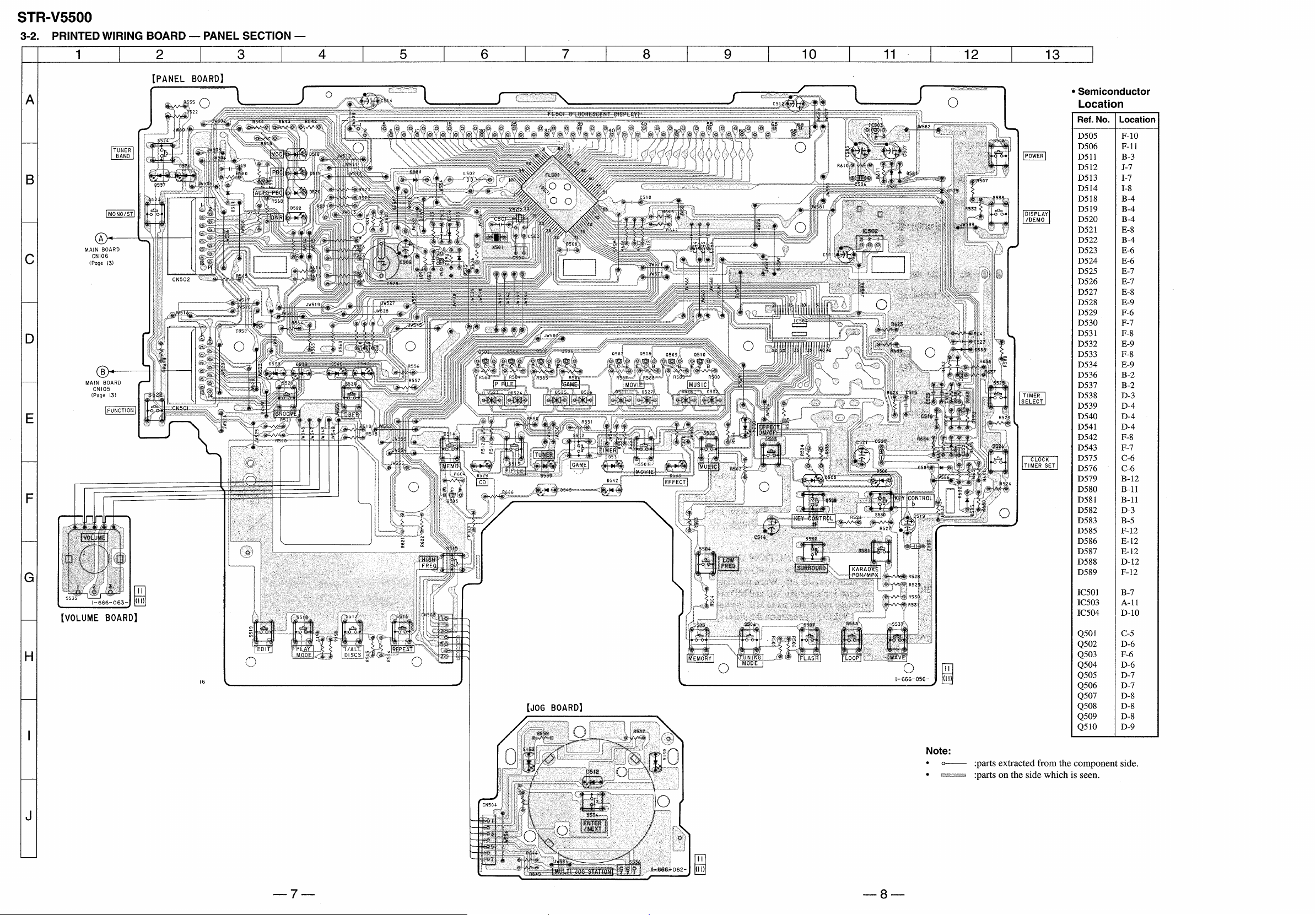
3-2. Printed Wiring Board — Panel Section —·························7
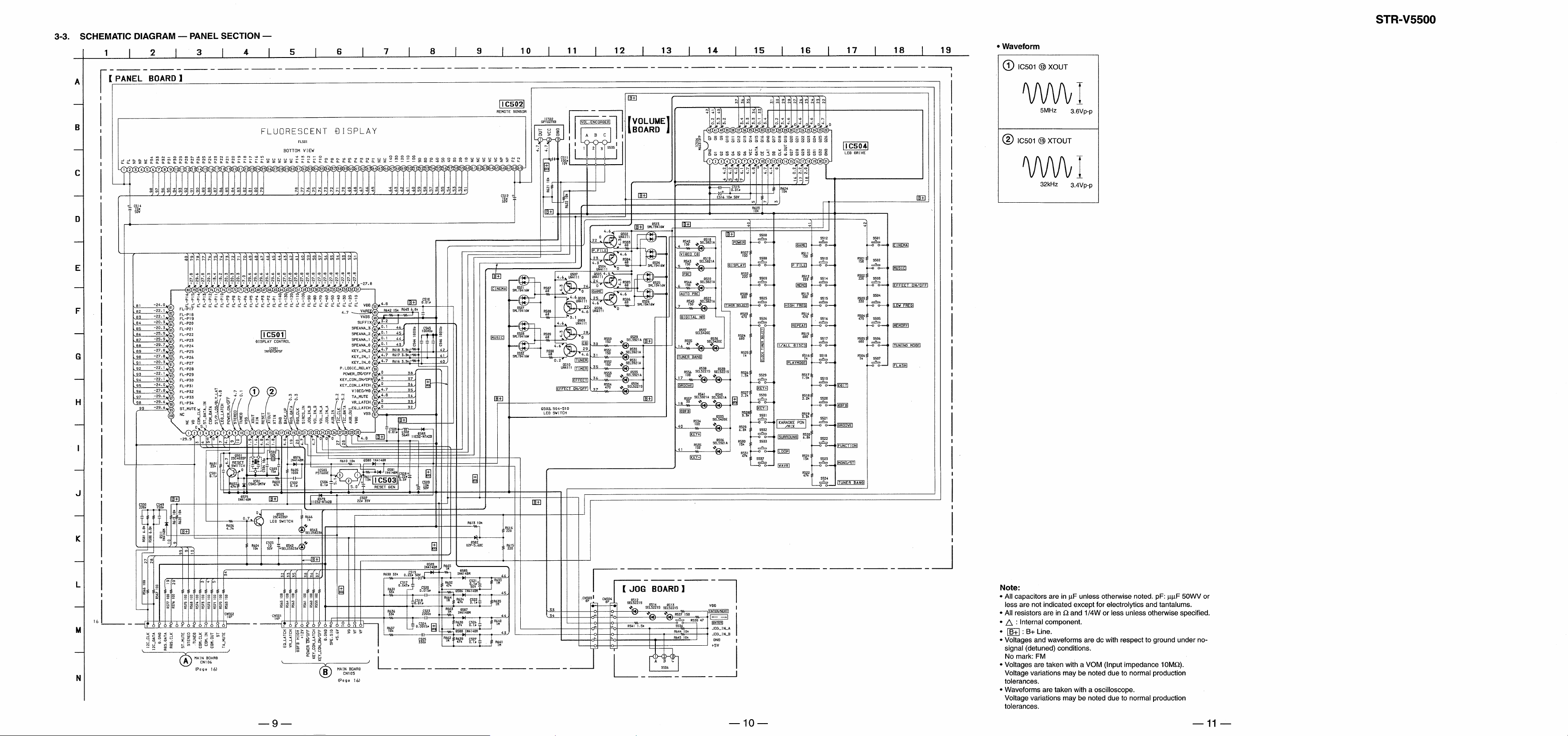
3-3. Schematic Diagram — Panel Section — ··························· 9
3-4. Printed Wiring Board — Main Section — ······················· 12
3-5. Schematic Diagram — Main Section — ·························· 15
3-6. Printed Wiring Board and Schematic Diagram
— Power Section —·························································19
3-7. IC Pin Function ································································ 23
3-8. IC Block Diagrams ··························································· 24
4. EXPLODED VIEWS
4-1. Main Section····································································· 25
4-2. Panel Section ···································································· 26
5. ELECTRICAL PARTS LIST ··································· 27
SAFETY-RELATED COMPONENT WARNING!!
COMPONENTS IDENTIFIED BY MARK ! OR DOTTED LINE WITH
MARK ! ON THE SCHEMATIC DIAGRAMS AND IN THE PARTS
LIST ARE CRITICAL TO SAFE OPERATION. REPLACE THESE
COMPONENTS WITH SONY PARTS WHOSE PART NUMBERS
APPEAR AS SHOWN IN THIS MANUAL OR IN SUPPLEMENTS
PUBLISHED BY SONY.
Notes on chip component replacement
• Never reuse a disconnected chip component.
• Notice that the minus side of a tentalum capacitor may be damaged
by heat.
— 2 —
Page 3
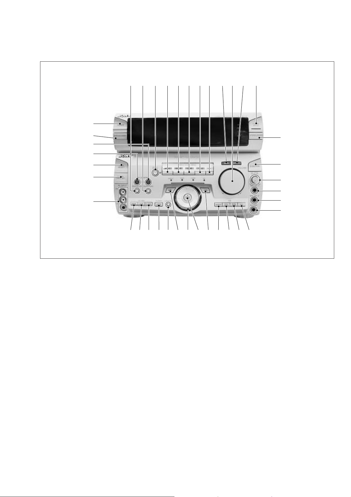
— FRONT PANEL —
SECTION 1
GENERAL
12345678 9!º!¡ !™
#•
#¶
#§
#∞
#¢
#£
#™
1 KARAOKE PON/MPX button
2 SURROUND button
3 EFFECT ON/OFF button
4 MUSIC button
5 MOVIE button
6 GAME button
7 P FILE button
8 MEMO button
9 DBFB button
!º VOLUME
!¡ GROOVE button
!™ TUNER BAND button
!£ STEREO/MONO button
!¢ FUNCTION button
!∞ MIC LEVEL/ECHO VOL
!§ MIX MIC 1 jack
!¶ MIX MIC 2 jack
!• PHONES jack
!ª EDIT button
#¡
!£
!¢
!∞
!§
!¶
!•
!ª@º@¡@™@£@¢@¶ @∞@§@•@ª#º
@º PLAY MODE button
@¡ 1/ALL DISCS button
@™ REPEAT button
@£ HIGH FREQ button
@¢ ENTER/NEXT button
@∞ MULTI JOG STATION dial
@§ LOW FREQ button
@¶ MEMORY button
@• TUNING MODE button
@ª FLASH button
#º LOOP button
#¡ WAVE button
#™ AV INPUT jack
#£ CLOCK TIMER SET button
#¢ TIMER SELECT button
#∞ KEY CONTROL ˜ button
#§ KEY CONTROL n button
#¶ DISPLAY/DEMO button
#• POWER button
— 3 —
Page 4
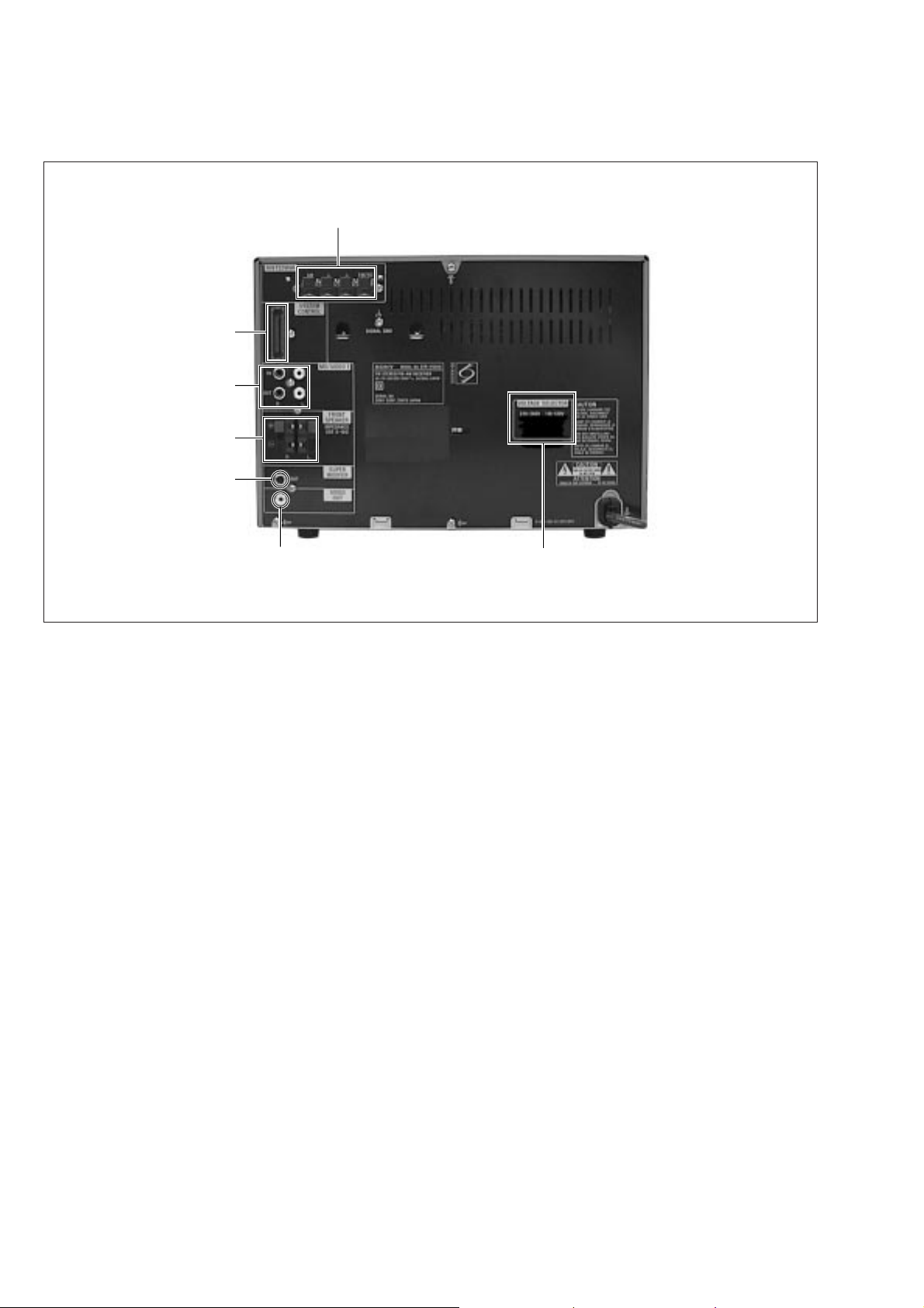
— BACK PANEL —
#ª
$º
$¡
$™
$£
$¢
#ª ANTENNA terminal
$º SYSTEM CONTROL
$¡ MD/VIDEO 1 jack
$™ FRONT SPEAKER terminal
$£ SUPER WOOFER jack
$¢ VIDEO OUT jack
$∞ VOLTAGE SELECTOR switch
$∞
— 4 —
Page 5
SECTION 2
D
TEST MODE
SECTION 3
DIAGRAMS
FL DISPLAY/KEY LED TEST MODE
Press the REPEAT, ENTER/NEXT and SURROUND buttons
simultaneously.
1. All FL segments and all LEDs turn on.
2. To access the microprocessor information, press the P FILE
key . Each pressing of the P FILE ke y adv ances the display on
the FL tube in the following sequence.
STR microprocessor version number
HCD microprocessor version number
VCD microprocessor version number (VCD model only)
Model name
Destination
3. To check the encoder, press the MUSIC key. The following
display appears on the FL tube.
"K0J0V0"
The number after K indicates the number of times that the key is
pressed. The key which was pressed in the past, is not counted.
The key which is pressed hereafter is counted. Pressing any key
increases the number after K.
The number after J indicates the number of rotations that the JOG
dial is rotated. Turning the JOG dial clockwise increases the number
after J. Turning the JOG dial counter-clockwise decreases the
number after J.
The number after V indicates the number of rotations that the
VOLUME dial is rotated. Turning the VOLUME dial clockwise
increases the number after V. Turning the VOLUME dial counterclockwise decreases the number after V.
To exit this mode, perform the "Cold Reset" (reset clearing memory)
as described below.
GENERAL TEST MODE
(INCLUDING AMPLIFIER AND TUNER)
Press the REPEAT, ENTER/NEXT and CLOCK TIMER SET
buttons simultaneously while the main power is on.
1. Sound volume display segment starts blinking.
2. The tuning enters the PRESET mode.
3. Rotating the VOLUME control clockwise increases the v olume
level to maximum.
Rotating the VOLUME control counter-clockwise decreases
the volume level to minimum.
4. Pressing the MUSIC key decreases the equalizer curve to
minimum and "EQ CHECK" appears on the display.
Pressing the MOVIE key increases the equalizer curve to
maximum.
Pressing the GAME key makes the equalizer curve flat.
5. Pressing any of the DBFB, GROOVE or SURROUND key
disappears "EQ CHECK" on the display.
To exit this mode, perform the "Cold Reset" (reset clearing memory)
as described below.
AGING MODE
1. CD aging mode
To ex ecute the CD aging, set the three discs to the CD tray and
set the function to CD. REPEAT, ENTER/NEXT and LOOP
buttons simultaneously. The CD a ging mode starts and the disc
calendar starts blinking.
2. Tape aging mode
To ex ecute the tape aging, set the two tapes to the tape A and B
drives. Set the function to T APE. Press the REPEAT , ENTER/
NEXT and LOOP buttons simultaneously. Press the A forward
key to start the tape aging mode. "AGING" appears on the
display.
CD SERVICE MODE
Turn on the main power. Press the REPEAT, ENTER/NEXT and
KARAOKE PON/MPX buttons simultaneously.
VACS toggles between ON and OFF.
VACS LEVEL DISPLAY
Turn on the main power. Press the EDIT, ENTER/NEXT and
KARAOKE PON/MPX buttons simultaneously.
VACS level appears on the display.
CD SHIP MODE
Turn on the main power. Press the PLAY MODE and POWER
buttons simultaneously.
The main power is turned off and LOCK appears on the display.
TUNER STEP CHANGE
Turn on the main power. Set the function to TUNER. Select MW
band from the present tuning.
Turn off the main power. Press the ENTER/NEXT and POWER
buttons simultaneously. The main power is turned on and the
changed step appears on the display.
MD/VIDEO 1 FUNCTION CHANGE
Press the FUNCTION and POWER buttons simultaneously while
the main power is off. When the function is set to VIDEO 1, the
function is changed to MD and MD appears on the display.
When the function is set to MD, the function is changed to VIDEO
1 and VIDEO 1 appears on the display.
COLD RESET (Reset which clears memory.)
Press the REPEAT, ENTER/NEXT and DISPLAY buttons
simultaneously at any time. The system is reset while clearing
memory.
HOT RESET
(Reset which does not clear memory.)
Press the REPEAT, ENTER/NEXT and TIMER SELECT buttons
simultaneously at any time. The system is reset without clearing
memory.
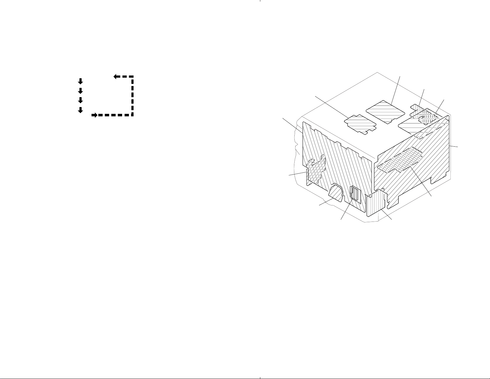
3-1. CIRCUIT BOARDS LOCATION
SEC BOARD
PANEL BOARD
AVIN BOARD
JOG BOARD
VOLUME BOARD
PRI BOARD
DUMMY BOARD
ENCAPSULATED COMPONENT
MAIN BOAR
AMP BOARD
MIC ECHO BOARD
— 5 —
— 6 —
Page 6
Page 7
Page 8

Page 9

Page 10

Page 11

3-7. IC PIN FUNCTION
• IC501 TMP87CM75F-6608 (DISPLAY CONTROL)
Pin No.
1
2
3
4
5
6
7
8
9
10
11
12
13
14
15
16
17
18
19
20
21
22
23
24
25
26
27
28
29
30
31
32
33
34
35
36
37
38
39
40 to 42
43 to 46
47
48
49
50
51 to 64
65 to 98
99
100
Pin Name
NC
VG
COM CLK
ST DATA IN
COM DATA
ST CE
LED LAT
POWER ON/OFF
STEREO
TUNED
Vss
X OUT
X IN
RESET
XT OUT
XT IN
GND
BACK UP
RDS DATA
RDS CLK
SIRCS IN
JOG IN B
VOL IN B
VOL IN A
JOG IN A
AUB IN
12C CLK
12C DATA
AUB OUT
VDD
Vss
EQ LAT
VR LAT
TA MUTE
VIDEO MD
KEY CON LAT
KEY CON ON/OFF
POWER ON/OFF
P LOG RELAY
KEY IN 0 to 2
SPEANA 0 to 3
SUFFIX
VASS
VAREF
VDD
FL–1G to 14G
FL–P1 to P34
ST MUTE
NC
I/O
—
—
O
O
O
O
O
—
O
O
—
—
I/O
I/O
—
—
—
O
O
O
O
O
O
O
—
—
—
—
O
O
O
—
Not used
POWER SUPPLY FOR VFT DRIVER
Transfer clock output serial data
I
Serial data input
Serial data output
Chip enable output
Latch output to IC504
H : D542, D543 ON
I
Stereo signal input
I
Tuned signal input
Power supply (Ground)
Oscillator connection terminal (8MHz)
I
Oscillator connection terminal (8MHz)
I
Reset signal input terminal
Oscillator connection terminal (32.768kHz)
I
Oscillator connection terminal (32.768kHz)
Not used (Ground)
I
AC Power supply off
I
RDS DATA input (European model only)
I
RDS clock input (European model only)
I
SIRCS signal input
I
JOG dial encoder input
I
Volum encoder input
I
Volum encoder input
I
JOG dial encoder input
Not used
12C clock I/O
12C data I/O
Not used
Power supply (5V)
Power supply (Ground)
Latch output to IC105
Latch output to IC2002
Mute output to transistor L : Mute ON
DBFB level control output L : DBFB HIGH
Latch output to IC6003
H : Key con ON
L : SP relay ON
Not used
I
Key data input (A/D converter)
I
Spectrum analyzer signal input
I
Input for model select
Power supply for analog (Ground)
Power supply (+5V)
Power supply (Ground)
Grid output to FL501
Segment output to FL501
H : MUTE L : Signal Receiving
Not used
Description
— 23 —
Page 12

3-8. IC BLOCK DIAGRAMS
IC105 M62427FP-A
F1 F2
NC6
REC 2C
REC 2B
REC 2A
NC7
KEY OUT2
63 626160 59 58 57 56 55
64
F1 O2
F1 IN2
F2 F2
F2 O2
5354
F2 IN2
52
46
45
4748495051
44 43
41
42
BB12
BBIN2
VOL OUT2
VOL IN2
F OUT2
F5 F2
F4 IN2
F4 O2
F4 F2
F3 IN2
F3 O2
F3 F2
65
KEY IN2
66
BPF OUT
67
BPF IN
68
NC8
69
IN 2B
70
NC9
71
IN 2A
72
AVSS
73
AGND
74
IN 1A
75
NC1
76
IN 1B
77
NC2
78
DELAY IN
DELAY OUT
79
80
KEY IN1
1
2
NC3
KEY OUT1
IC850 µPC1237HA
3
REC 1A
–
+
+
–
4
REC 1B
5
REC 1C
40
BBIN1
BB11
39
38
37
36
35
34
33
32
31
30
29
28
27
26
25
BB22
BUF IN1
BUF OUT1
NC5
AVDD
DGND
LATCH
DATA
CLOCK
DVDD
PORT C
PORT B
PORT A
BUFOUT1
BUFIN1
BB21
SBAND GRAPHIC EQUALIZER
+
–
+
18
–
+
F4 IN1
–
+
–
U-CON
INTER
FACE
–
+
+
–
–
+
19
F5 F1
F OUT1
21
VOL IN1
22
VOL OUT1
23 24
+
–
–
+
+
–
SBAND GRAPHIC EQUALIZER
6
NC4
7
8 9
F1 F1
11
10 20
F2 F1
F1 O1
F1 IN1
F2 O1
+
–
–
+
–
+
12
F2 IN1
14
13
F3 F1
F3 O1
F3 IN1
F4 F1
171615
F4 O1
OVER LOAD DET
CC
ON
V
MUTE
OFFSET DET
LATCH/
AUTORESET
AC OFF
DET
F/F
1 2 3 4 5 6 7 8
IC6003 M65847FP IC6002 M65850P
MODE2
28
1
ADCONT
MODE1
27
D/A
2
DA1CONT
DAIINTOUT
DAIINTIN
ADINTOUT
25
26
24
A/D
RESET RAM
3
DA2CONT
4 5
KEY DOWN
6
KEY UP
LPF1IN
LPF1OUT
HPFIN
HPFOUT
ADINTIN
21
LPF1
20
–
+
22
23
–
+
REF REF REF REF
GENERATOR
LPF2IN
19
18
–
+
HPF LPF2 MIX
CLOCK
LOGIC
7
CLKO/KEY0
SDATA/KEY1
8
9
SCK/KEY2
10
KEY4
STROBE/KEY3
11
KEY5
LPF2OUT
17
REF
12
REF
13
MIXIN
16
–
+
GND
MIXOUT
15
14
VCC
VCC
OSCILLATOR
1/2 VCC
CLOCK
AUTO
RESET
RESET
LPF1
2 345 6 7
1
LPF1IN
LPF1OUT
V
CC
CLOCK
MAIN
CONTROL
D1
A/D
OP1OUT
REF
OP1IN
DO0
DO1
CC1
OP2IN
D/A
MO
MI
OP2OUT
LPF2IN
20KBIT
CC2
LPF2OUT
891014 13 12 11
LPF2
SRAM
GND
— 24 —
Page 13

Note:
• -XX, -X mean standardized parts, so they may
have some differences from the original one.
• Items marked “*” are not stocked since they
are seldom required for routine service. Some
delay should be anticipated when ordering these
items.
4-1. MAIN SECTION
2
#1
1
SECTION 4
EXPLODED VIEWS
• The mechanical parts with no reference number
in the exploded views are not supplied.
• Hardware (# mark) list and accessories and
packing materials are given in the last of this
parts list.
• Abbreviation
MY : Malaysia SP : Singapore
HK : Hong Kong IA : Indonesian
CH : Chinese
3
4
not supplied
#2
#2
#4
The components identified by mark ! or
dotted line with mark ! are critical for safety .
Replace only with part number specified.
8
#3
#3
1
#3
CH MODEL
12
#3
T901
11
not supplied
IA MODEL
12
not supplied
13
#3
10
HK MODEL
5
7
IC901
#5
6
9
#3
13
MY, SP, HK MODEL
12
MY, SP
MODEL
13
Ref. No. Part No. Description Remarks Ref. No. Part No. Description Remarks
1 3-363-099-11 SCREW (CASE 3 TP2)
* 2 4-991-364-11 CASE
* 3 1-666-059-11 SEC BOARD
* 4 1-666-065-11 PRI BOARD
* 5 1-666-066-11 AMP BOARD
6 1-233-546-21 ENCAPSULATED COMPONENT
* 7 1-666-067-11 DUMMY BOARD
* 8 4-991-361-01 PANEL (VCD), BACK (MY,SP)
* 8 4-991-361-11 PANEL (VCD), BACK (CH)
* 8 4-991-361-21 PANEL (VCD), BACK (HK)
* 8 4-991-361-31 PANEL (VCD), BACK (IA)
* 9 A-4403-202-A MAIN BOARD, COMPLETE
10 4-970-381-11 FOOT (REAR)
* 11 3-703-244-00 BUSHING (2104), CORD (IA)
11 3-703-571-11 BUSHING (S) (4516), CORD (MY,SP,HK,CH)
! 12 1-777-071-21 CORD, POWER (MY,SP,HK)
! 12 1-782-315-11 CORD, POWER (IA)
! 12 1-782-464-21 CORD, POWER (CH)
! 13 1-569-007-11 ADAPTOR, CONVERSION 2P (IA)
! 13 1-569-008-21 ADAPTOR, CONVERSION 2P (MY,SP)
! 13 1-770-019-11 ADAPTOR, CONVERSION PLUG 3P (HK)
! T901 1-431-365-11 TRANSFORMER, POWER
— 25 —
Page 14

4-2. PANEL SECTION
56
FL501
58
59
63
60
62
61
57
65
65
64
65
65
65
66
53
55
67
52
54
51
Ref. No. Part No. Description Remarks Ref. No. Part No. Description Remarks
51 4-991-318-01 KNOB (VOL)
52 4-991-326-01 KNOB (CENTER)
53 4-991-317-01 KNOB (JOG)
54 4-977-358-11 CUSHION
55 X-4948-895-1 PANEL ASSY, FRONT
56 4-962-708-11 EMBLEM (4-A), SONY
57 X-4948-612-1 DISPLAY ASSY, BUTTON
* 58 4-932-810-11 CUSHION (FL)
* 59 4-986-870-01 HOLDER, FL TUBE
* 60 1-606-060-11 AVIN BOARD
* 61 1-666-062-11 JOG BOARD
62 X-4948-611-1 BUTTON (E/N) ASSY
63 4-984-085-01 SPRING (ENTER), COMPRESSION
* 64 A-4403-204-A PANEL BOARD, COMPLETE
65 4-951-620-01 SCREW (2.6X8), +BVTP
* 66 A-4403-207-A MIC ECHO BOARD, COMPLET
67 4-991-327-01 KNOB (CONTROL)
FL501 1-517-618-11 INDICATOR TUBE, FLUORESCENT
— 26 —
Page 15

SECTION 5
AMP
Note:
When indicating parts by reference number,
please include the board name.
The components identified by mark ! or
dotted line with mark ! are critical for safety .
Replace only with part number specified.
• Due to standardization, replacements in the
parts list may be different from the parts
specified in the diagrams or the components
used on the set.
• -XX, -X mean standardized parts, so they
may have some difference from the original
one.
Ref. No. Part No. Description Remarks Ref. No. Part No. Description Remarks
* 1-666-066-11 AMP BOARD
*********
< CAPACITOR >
C809 1-104-664-11 ELECT 47uF 20% 25V
C810 1-104-664-11 ELECT 47uF 20% 25V
C811 1-126-933-11 ELECT 100uF 20% 16V
C812 1-104-664-11 ELECT 47uF 20% 25V
C813 1-104-664-11 ELECT 47uF 20% 25V
C816 1-104-664-11 ELECT 47uF 20% 25V
C817 1-126-933-11 ELECT 100uF 20% 10V
C818 1-104-664-11 ELECT 47uF 20% 25V
C819 1-104-664-11 ELECT 47uF 20% 25V
C901 1-126-961-11 ELECT 2.2uF 20% 50V
C902 1-162-294-31 CERAMIC 0.001uF 10% 50V
C903 1-162-282-31 CERAMIC 100PF 10% 50V
C904 1-126-967-11 ELECT 47uF 20% 50V
C905 1-126-967-11 ELECT 47uF 20% 50V
C906 1-136-495-11 FILM 0.068uF 5% 50V
C907 1-136-495-11 FILM 0.068uF 5% 50V
C932 1-128-552-51 ELECT 47uF 20% 63V
C933 1-128-581-11 ELECT 4.7uF 20% 63V
C934 1-128-552-51 ELECT 47uF 20% 63V
C937 1-126-965-11 ELECT 22uF 20% 50V
C938 1-126-934-11 ELECT 220uF 20% 16V
C940 1-128-581-11 ELECT 4.7uF 20% 63V
C950 1-162-306-11 CERAMIC 0.01uF 20% 16V
C951 1-126-963-11 ELECT 4.7uF 20% 50V
C952 1-162-294-31 CERAMIC 0.001uF 10% 50V
C953 1-162-282-31 CERAMIC 100PF 10% 50V
C954 1-126-967-11 ELECT 47uF 20% 50V
C955 1-126-967-11 ELECT 47uF 20% 50V
C956 1-136-495-11 FILM 0.068uF 5% 50V
C957 1-136-495-11 FILM 0.068uF 5% 50V
< DIODE >
D805 8-719-933-50 DIODE HZS7C2L
D806 8-719-001-57 DIODE UZL-11H3-TP
D807 8-719-000-81 DIODE UZL-7L3
D808 8-719-933-50 DIODE HZS7C2L
D903 8-719-987-63 DIODE 1N4148M
D953 8-719-987-63 DIODE 1N4148M
< IC >
IC901 8-749-921-04 IC STK-4211MK-2
ELECTRICAL PARTS LIST
• Items marked “*” are not stocked since they
are seldom required for routine service. Some
delay should be anticipated when ordering these
items.
• CAPA CITORS:
uF: µF
• RESISTORS
All resistors are in ohms.
METAL: metal-film resistor
METAL OXIDE: Metal Oxide-film resistor
F: nonflammable
Q802 8-729-209-15 TRANSISTOR 2SD2012
Q803 8-729-209-15 TRANSISTOR 2SD2012
Q804 8-729-209-15 TRANSISTOR 2SD2012
Q805 8-729-141-83 TRANSISTOR 2SB1094-LK
Q901 8-729-900-36 TRANSISTOR DTC124ES
Q902 8-729-140-84 TRANSISTOR 2SC1841-PAFAEA
Q952 8-729-140-84 TRANSISTOR 2SC1841-PAFAEA
Q8004 8-729-620-05 TRANSISTOR 2SC2603-EF
R805 1-249-428-11 CARBON 8.2K 5% 1/4W F
R807 1-247-843-11 CARBON 3.3K 5% 1/4W
R809 1-249-428-11 CARBON 8.2K 5% 1/4W F
R814 1-249-421-11 CARBON 2.2K 5% 1/4W F
R815 1-249-421-11 CARBON 2.2K 5% 1/4W F
R901 1-249-417-11 CARBON 1K 5% 1/4W F
R902 1-249-437-11 CARBON 47K 5% 1/4W
R903 1-249-412-11 CARBON 390 5% 1/4W F
R904 1-249-437-11 CARBON 47K 5% 1/4W
R906 1-249-429-11 CARBON 10K 5% 1/4W
R907 1-249-429-11 CARBON 10K 5% 1/4W
R908 1-249-429-11 CARBON 10K 5% 1/4W
R909 1-249-429-11 CARBON 10K 5% 1/4W
R910 1-249-397-11 CARBON 22 5% 1/4W F
R911 1-249-397-11 CARBON 22 5% 1/4W F
R913 1-249-417-11 CARBON 1K 5% 1/4W F
R914 1-249-431-11 CARBON 15K 5% 1/4W
R915 1-249-441-11 CARBON 100K 5% 1/4W
! R920 1-217-156-00 WIREWOUND 0.22 10% 5W F
! R932 1-212-881-11 FUSIBLE 100 5% 1/4W F
R933 1-249-421-11 CARBON 2.2K 5% 1/4W F
R934 1-249-421-11 CARBON 2.2K 5% 1/4W F
R935 1-249-421-11 CARBON 2.2K 5% 1/4W F
R936 1-249-421-11 CARBON 2.2K 5% 1/4W F
R937 1-249-437-11 CARBON 47K 5% 1/4W
R938 1-249-441-11 CARBON 100K 5% 1/4W
R939 1-249-433-11 CARBON 22K 5% 1/4W
R940 1-249-433-11 CARBON 22K 5% 1/4W
R941 1-249-429-11 CARBON 10K 5% 1/4W
R942 1-249-413-11 CARBON 470 5% 1/4W F
! R943 1-212-881-11 FUSIBLE 100 5% 1/4W F
R945 1-249-417-11 CARBON 1K 5% 1/4W F
R951 1-249-417-11 CARBON 1K 5% 1/4W F
R952 1-249-437-11 CARBON 47K 5% 1/4W
R953 1-249-412-11 CARBON 390 5% 1/4W F
• COILS
uH: µH
• SEMICONDUCTORS
In each case, u: µ, for example:
uA...: µA... , uPA... , µPA... ,
uPB... , µPB... , uPC... , µPC... ,
uPD..., µPD...
• Abbreviation
MY : Malaysia SP : Singapore
HK : Hong Kong IA : Indonesian
CH : Chinese
< TRANSISTOR >
< RESISTOR >
— 27 —
Page 16

AMP AVIN JOG MAIN
Ref. No. Part No. Description Remarks Ref. No. Part No. Description Remarks
R954 1-249-437-11 CARBON 47K 5% 1/4W
R956 1-249-429-11 CARBON 10K 5% 1/4W
R957 1-249-429-11 CARBON 10K 5% 1/4W
R958 1-249-429-11 CARBON 10K 5% 1/4W
R959 1-249-429-11 CARBON 10K 5% 1/4W
R960 1-249-397-11 CARBON 22 5% 1/4W F
R961 1-249-397-11 CARBON 22 5% 1/4W F
R963 1-249-417-11 CARBON 1K 5% 1/4W F
R964 1-249-431-11 CARBON 15K 5% 1/4W
R965 1-249-441-11 CARBON 100K 5% 1/4W
! R970 1-217-156-00 WIREWOUND 0.22 10% 5W F
! R974 1-212-849-00 FUSIBLE 4.7 5% 1/4W F
************************************************************
* A-4403-202-A MAIN BOARD,COMPLETE
********************
< CAPACITOR >
C101 1-136-167-00 FILM 0.15uF 5% 50V
C102 1-130-471-00 MYLAR 0.001uF 5% 50V
C103 1-136-169-00 FILM 0.22uF 5% 50V
C104 1-136-169-00 FILM 0.22uF 5% 50V
C105 1-136-495-11 FILM 0.068uF 5% 50V
C106 1-136-495-11 FILM 0.068uF 5% 50V
C107 1-137-440-11 FILM 0.018uF 5% 50V
C108 1-137-440-11 FILM 0.018uF 5% 50V
C109 1-137-437-11 FILM 0.0056uF 5% 50V
C110 1-130-479-00 MYLAR 0.0047uF 5% 50V
* 1-666-060-11 AVIN BOARD
**********
< CAPACITOR >
C6301 1-162-286-31 CERAMIC 220PF 10% 50V
C6302 1-162-286-31 CERAMIC 220PF 10% 50V
C6303 1-162-306-11 CERAMIC 0.01uF 20% 16V
< CONNECTOR >
CN6301 1-564-524-11 PLUG, CONNECTOR 9P
< DIODE >
D6300 8-719-987-63 DIODE 1N4148M
< JACK >
J6301 1-779-583-11 JACK, PIN 3P (AV INPUT)
< RESISTOR >
R6301 1-249-417-11 CARBON 1K 5% 1/4W F
R6302 1-249-417-11 CARBON 1K 5% 1/4W F
R6303 1-249-441-11 CARBON 100K 5% 1/4W
R6304 1-249-441-11 CARBON 100K 5% 1/4W
< RELAY >
C111 1-130-479-00 MYLAR 0.0047uF 5% 50V
C112 1-126-964-11 ELECT 10uF 20% 50V
C113 1-126-963-11 ELECT 4.7uF 20% 50V
C114 1-136-166-00 FILM 0.12uF 5% 50V
C115 1-136-166-00 FILM 0.12uF 5% 50V
C116 1-126-961-11 ELECT 2.2uF 20% 50V
C117 1-162-306-11 CERAMIC 0.01uF 20% 16V
C118 1-126-964-11 ELECT 10uF 20% 50V
C120 1-126-959-11 ELECT 0.47uF 20% 50V
C123 1-126-963-11 ELECT 4.7uF 20% 50V
C129 1-162-294-31 CERAMIC 0.001uF 10% 50V
C130 1-164-159-11 CERAMIC 0.1uF 50V
C140 1-162-306-11 CERAMIC 0.01uF 20% 16V
C153 1-136-169-00 FILM 0.22uF 5% 50V
C154 1-136-169-00 FILM 0.22uF 5% 50V
C155 1-136-495-11 FILM 0.068uF 5% 50V
C156 1-136-495-11 FILM 0.068uF 5% 50V
C157 1-137-440-11 FILM 0.018uF 5% 50V
C158 1-137-440-11 FILM 0.018uF 5% 50V
C159 1-137-437-11 FILM 0.0056uF 5% 50V
C160 1-130-479-00 MYLAR 0.0047uF 5% 50V
C161 1-130-479-00 MYLAR 0.0047uF 5% 50V
C162 1-126-964-11 ELECT 10uF 20% 50V
C163 1-126-963-11 ELECT 4.7uF 20% 50V
C164 1-136-166-00 FILM 0.12uF 5% 50V
RY6300 1-515-622-11 RELAY
************************************************************
* 1-666-062-11 JOG BOARD
**********
< DIODE >
D512 8-719-046-44 DIODE SEL5221S (ENTER/NEXT)
D513 8-719-046-44 DIODE SEL5221S (→)
D514 8-719-046-44 DIODE SEL5221S (←)
< RESISTOR >
R537 1-249-407-11 CARBON 150 5% 1/4W F
R538 1-249-401-11 CARBON 47 5% 1/4W F
R541 1-249-419-11 CARBON 1.5K 5% 1/4W F
R644 1-249-429-11 CARBON 10K 5% 1/4W
R645 1-249-429-11 CARBON 10K 5% 1/4W
< SWITCH >
S534 1-762-751-11 SWITCH, TACTILE (ENTER/NEXT)
S536 1-762-874-11 SWITCH, JOG (MULTI JOG STATION)
************************************************************
— 28 —
C165 1-136-166-00 FILM 0.12uF 5% 50V
C166 1-126-961-11 ELECT 2.2uF 20% 50V
C177 1-162-306-11 CERAMIC 0.01uF 20% 16V
C181 1-162-215-31 CERAMIC 47PF 5% 50V
C182 1-126-960-11 ELECT 1uF 20% 50V
C183 1-126-961-11 ELECT 2.2uF 20% 50V
C188 1-126-964-11 ELECT 10uF 20% 50V
C703 1-126-963-11 ELECT 4.7uF 20% 50V
C731 1-126-964-11 ELECT 10uF 20% 50V
C732 1-126-964-11 ELECT 10uF 20% 50V
C753 1-126-963-11 ELECT 4.7uF 20% 50V
C801 1-136-165-00 FILM 0.1uF 5% 50V
C802 1-136-165-00 FILM 0.1uF 5% 50V
C803 1-104-482-11 ELECT 4700uF 20% 63V
C804 1-104-482-11 ELECT 4700uF 20% 63V
The components identified by mark ! or dotted
line with mark ! are critical for safety.
Replace only with part number specified.
Page 17

MAIN
Ref. No. Part No. Description Remarks Ref. No. Part No. Description Remarks
C807 1-126-964-11 ELECT 10uF 20% 50V
C808 1-126-948-11 ELECT 100uF 20% 35V
C831 1-126-942-61 ELECT 1000uF 20% 25V
C832 1-126-942-61 ELECT 1000uF 20% 25V
C835 1-136-165-00 FILM 0.1uF 5% 50V
* E801 1-537-738-21 TERMINAL, EARTH
< TERMINAL >
< IC >
C836 1-136-165-00 FILM 0.1uF 5% 50V
C852 1-126-923-11 ELECT 220uF 20% 10V
C853 1-126-933-11 ELECT 100uF 20% 10V
C858 1-104-664-11 ELECT 47uF 20% 25V
C859 1-126-961-11 ELECT 2.2uF 20% 50V
C861 1-164-159-11 CERAMIC 0.1uF 50V
C6100 1-162-284-31 CERAMIC 150PF 10% 50V
C6101 1-126-964-11 ELECT 10uF 20% 50V
C6102 1-162-290-31 CERAMIC 470PF 10% 50V
C6103 1-162-291-31 CERAMIC 560PF 10% 50V
C6104 1-249-429-11 CARBON 10K 5% 1/4W
C6106 1-162-294-31 CERAMIC 0.001uF 10% 50V
C6107 1-164-159-11 CERAMIC 0.1uF 50V
C6108 1-164-159-11 CERAMIC 0.1uF 50V
C6109 1-136-495-11 FILM 0.068uF 5% 50V
C6110 1-136-495-11 FILM 0.068uF 5% 50V
C6111 1-136-495-11 FILM 0.068uF 5% 50V
C6112 1-162-286-31 CERAMIC 220PF 10% 50V
C6113 1-162-286-31 CERAMIC 220PF 10% 50V
C6114 1-162-294-31 CERAMIC 0.001uF 10% 50V
C6115 1-164-159-11 CERAMIC 0.1uF 50V
C6116 1-126-967-11 ELECT 47uF 20% 10V
C6117 1-164-159-11 CERAMIC 0.1uF 50V
C6118 1-124-584-00 ELECT 100uF 20% 10V
C6119 1-126-964-11 ELECT 10uF 20% 50V
C6120 1-126-964-11 ELECT 10uF 20% 50V
C6121 1-126-964-11 ELECT 10uF 20% 50V
C6123 1-162-306-11 CERAMIC 0.01uF 20% 16V
C6125 1-249-429-11 CARBON 10K 5% 1/4W
< CONNECTOR >
IC101 8-759-634-50 IC M5218AL
IC105 8-759-460-02 IC M62427FP-A
IC701 8-759-000-47 IC MC14051BCP
IC751 8-759-000-47 IC MC14051BCP
IC850 8-759-111-68 IC uPC1237HA
IC6003 8-759-370-84 IC M65847FP
IC6004 8-759-140-53 IC uPD4053BC
< JACK >
J701 1-770-614-11 JACK, PIN 4P (MD/VIDEO 1)
J901 1-779-379-11 JACK, PIN 2P (SUPER WOOFER/MONITOR)
< COIL >
L6100 1-410-521-11 INDUCTOR 100uH
< TRANSISTOR >
Q111 8-729-119-78 TRANSISTOR 2SC403SP-51
Q112 8-729-119-78 TRANSISTOR 2SC403SP-51
Q161 8-729-119-78 TRANSISTOR 2SC403SP-51
Q162 8-729-119-78 TRANSISTOR 2SC403SP-51
Q190 8-729-900-63 TRANSISTOR DTA124ES
Q191 8-729-141-26 TRANSISTOR 2SC3622A-LK
Q192 8-729-141-26 TRANSISTOR 2SC3622A-LK
Q801 8-729-141-83 TRANSISTOR 2SB1094-LK
Q810 8-729-900-36 TRANSISTOR DTC124ES
Q856 8-729-900-36 TRANSISTOR DTC124ES
Q857 8-729-900-63 TRANSISTOR DTA124ES
Q2100 8-729-141-26 TRANSISTOR 2SC3622A-LK
Q6001 8-729-119-78 TRANSISTOR 2SC403SP-51
Q6002 8-729-900-80 TRANSISTOR DTC114ES
CN103 1-774-289-11 PIN, CONNECTOR (PC BOARD) 15P
CN105 1-774-336-11 SOCKET, CONNECTOR(PC BOARD) 14P
CN106 1-774-336-11 SOCKET, CONNECTOR(PC BOARD) 14P
* CN6002 1-568-937-11 PIN, CONNECTOR 10P
* CNP701 1-764-017-21 HOUSING,CONNECTOR(PC BOARD) 17P
< DIODE >
D101 8-719-987-63 DIODE 1N4148M
D102 8-719-987-63 DIODE 1N4148M
D702 8-719-024-99 DIODE 11ES2-NTA2B
D801 8-719-302-38 DIODE RBV-602-01
D804 8-719-934-22 DIODE HZS30-2L
D809 8-719-987-63 DIODE 1N4148M
D810 8-719-987-63 DIODE 1N4148M
D821 8-719-987-63 DIODE 1N4148M
D824 8-719-024-99 DIODE 11ES2-NTA2B
D831 8-719-024-99 DIODE 11ES2-NTA2B
D832 8-719-024-99 DIODE 11ES2-NTA2B
D833 8-719-024-99 DIODE 11ES2-NTA2B
D834 8-719-024-99 DIODE 11ES2-NTA2B
D840 8-719-987-63 DIODE 1N4148M
D841 8-719-987-63 DIODE 1N4148M
D844 8-719-024-99 DIODE 11ES2-NTA2B
D852 8-719-987-63 DIODE 1N4148M
D1021 8-719-987-63 DIODE 1N4148M
< RESISTOR >
R101 1-249-429-11 CARBON 10K 5% 1/4W
R102 1-249-429-11 CARBON 10K 5% 1/4W
R103 1-249-429-11 CARBON 10K 5% 1/4W
R104 1-249-429-11 CARBON 10K 5% 1/4W
R105 1-249-429-11 CARBON 10K 5% 1/4W
R108 1-247-897-11 CARBON 560K 5% 1/4W
R109 1-249-419-11 CARBON 1.5K 5% 1/4W F
R110 1-249-433-11 CARBON 22K 5% 1/4W
R111 1-249-441-11 CARBON 100K 5% 1/4W
R112 1-249-421-11 CARBON 2.2K 5% 1/4W F
R113 1-249-441-11 CARBON 100K 5% 1/4W
R115 1-249-439-11 CARBON 68K 5% 1/4W
R116 1-249-437-11 CARBON 47K 5% 1/4W
R117 1-247-903-00 CARBON 1M 5% 1/4W
R118 1-249-417-11 CARBON 1K 5% 1/4W F
R119 1-249-433-11 CARBON 22K 5% 1/4W
R120 1-249-437-11 CARBON 47K 5% 1/4W
R122 1-247-903-00 CARBON 1M 5% 1/4W
R123 1-249-431-11 CARBON 15K 5% 1/4W
R124 1-249-437-11 CARBON 47K 5% 1/4W
— 29 —
Page 18

MAIN
Ref. No. Part No. Description Remarks Ref. No. Part No. Description Remarks
R125 1-247-807-31 CARBON 100 5% 1/4W
R126 1-249-429-11 CARBON 10K 5% 1/4W
R129 1-247-887-00 CARBON 220K 5% 1/4W
R137 1-247-807-31 CARBON 100 5% 1/4W
R138 1-247-807-31 CARBON 100 5% 1/4W
R758 1-249-417-11 CARBON 1K 5% 1/4W F
R759 1-249-417-11 CARBON 1K 5% 1/4W F
R760 1-249-417-11 CARBON 1K 5% 1/4W F
R762 1-249-417-11 CARBON 1K 5% 1/4W F
! R801 1-212-982-00 FUSIBLE 100 5% 1/2W F
R139 1-247-807-31 CARBON 100 5% 1/4W
R140 1-247-807-31 CARBON 100 5% 1/4W
R141 1-247-807-31 CARBON 100 5% 1/4W
R142 1-247-807-31 CARBON 100 5% 1/4W
R143 1-247-807-31 CARBON 100 5% 1/4W
R144 1-247-807-31 CARBON 100 5% 1/4W
R145 1-247-807-31 CARBON 100 5% 1/4W
R146 1-247-807-31 CARBON 100 5% 1/4W
R147 1-247-807-31 CARBON 100 5% 1/4W
R151 1-249-429-11 CARBON 10K 5% 1/4W
R152 1-249-429-11 CARBON 10K 5% 1/4W
R153 1-249-429-11 CARBON 10K 5% 1/4W
R154 1-249-429-11 CARBON 10K 5% 1/4W
R155 1-249-429-11 CARBON 10K 5% 1/4W
R156 1-249-429-11 CARBON 10K 5% 1/4W
R158 1-247-897-11 CARBON 560K 5% 1/4W
R159 1-249-419-11 CARBON 1.5K 5% 1/4W F
R160 1-249-433-11 CARBON 22K 5% 1/4W
R161 1-249-441-11 CARBON 100K 5% 1/4W
R162 1-249-421-11 CARBON 2.2K 5% 1/4W F
R163 1-249-441-11 CARBON 100K 5% 1/4W
R165 1-249-439-11 CARBON 68K 5% 1/4W
R167 1-249-441-11 CARBON 100K 5% 1/4W
R172 1-247-903-00 CARBON 1M 5% 1/4W
R173 1-249-431-11 CARBON 15K 5% 1/4W
R174 1-249-437-11 CARBON 47K 5% 1/4W
R176 1-249-429-11 CARBON 10K 5% 1/4W
R177 1-249-437-11 CARBON 47K 5% 1/4W
R178 1-249-433-11 CARBON 22K 5% 1/4W
R181 1-247-895-00 CARBON 470K 5% 1/4W
R182 1-247-895-00 CARBON 470K 5% 1/4W
R183 1-249-435-11 CARBON 33K 5% 1/4W
R184 1-249-429-11 CARBON 10K 5% 1/4W
R185 1-247-843-11 CARBON 3.3K 5% 1/4W
R186 1-249-425-11 CARBON 4.7K 5% 1/4W F
R187 1-249-441-11 CARBON 100K 5% 1/4W
R188 1-249-417-11 CARBON 1K 5% 1/4W F
R190 1-249-441-11 CARBON 100K 5% 1/4W
R804 1-249-429-11 CARBON 10K 5% 1/4W
R818 1-249-427-11 CARBON 6.8K 5% 1/4W F
R819 1-249-427-11 CARBON 6.8K 5% 1/4W F
R840 1-249-429-11 CARBON 10K 5% 1/4W
R851 1-249-431-11 CARBON 15K 5% 1/4W
R853 1-249-397-11 CARBON 22 5% 1/4W F
R854 1-249-441-11 CARBON 100K 5% 1/4W
R856 1-249-429-11 CARBON 10K 5% 1/4W
R857 1-249-435-11 CARBON 33K 5% 1/4W
R858 1-249-437-11 CARBON 47K 5% 1/4W
R859 1-249-439-11 CARBON 68K 5% 1/4W
! R870 1-215-892-11 METAL OXIDE 1K 5% 2W F
R944 1-249-417-11 CARBON 1K 5% 1/4W F
R1002 1-249-429-11 CARBON 10K 5% 1/4W
R1020 1-249-425-11 CARBON 4.7K 5% 1/4W F
R1021 1-249-417-11 CARBON 1K 5% 1/4W F
R6100 1-249-429-11 CARBON 10K 5% 1/4W
R6101 1-247-807-31 CARBON 100 5% 1/4W
R6102 1-249-417-11 CARBON 1K 5% 1/4W F
R6103 1-249-433-11 CARBON 22K 5% 1/4W
R6105 1-249-431-11 CARBON 15K 5% 1/4W
R6106 1-249-424-11 CARBON 3.9K 5% 1/4W F
R6109 1-249-425-11 CARBON 4.7K 5% 1/4W F
R6111 1-247-903-00 CARBON 1M 5% 1/4W
R6112 1-249-425-11 CARBON 4.7K 5% 1/4W F
R6113 1-247-807-31 CARBON 100 5% 1/4W
R6115 1-249-441-11 CARBON 100K 5% 1/4W
R6116 1-249-433-11 CARBON 22K 5% 1/4W
R6117 1-249-433-11 CARBON 22K 5% 1/4W
R6118 1-249-441-11 CARBON 100K 5% 1/4W
R6119 1-249-441-11 CARBON 100K 5% 1/4W
R6120 1-249-441-11 CARBON 100K 5% 1/4W
R6124 1-249-417-11 CARBON 1K 5% 1/4W F
R6125 1-249-429-11 CARBON 10M 5% 1/4W
< RELAY >
RY801 1-515-920-11 RELAY (24V)
R192 1-249-425-11 CARBON 4.7K 5% 1/4W F
R195 1-249-425-11 CARBON 4.7K 5% 1/4W F
R196 1-247-807-31 CARBON 100 5% 1/4W
R702 1-249-425-11 CARBON 4.7K 5% 1/4W F
R703 1-249-425-11 CARBON 4.7K 5% 1/4W F
R704 1-249-417-11 CARBON 1K 5% 1/4W F
R705 1-249-441-11 CARBON 100K 5% 1/4W
R707 1-249-441-11 CARBON 100K 5% 1/4W
R708 1-249-417-11 CARBON 1K 5% 1/4W F
R710 1-249-417-11 CARBON 1K 5% 1/4W F
R752 1-249-425-11 CARBON 4.7K 5% 1/4W F
R753 1-249-425-11 CARBON 4.7K 5% 1/4W F
R754 1-249-417-11 CARBON 1K 5% 1/4W F
R755 1-249-441-11 CARBON 100K 5% 1/4W
R757 1-249-441-11 CARBON 100K 5% 1/4W
— 30 —
< TERMINAL >
TB901 1-537-240-31 TERMINAL BOARD (CHECKER PIN)
************************************************************
The components identified by mark ! or dotted
line with mark ! are critical for safety.
Replace only with part number specified.
Page 19

MIC ECHO PANEL VOLUME
Ref. No. Part No. Description Remarks Ref. No. Part No. Description Remarks
* A-4403-207-A MIC ECHO BOARD, COMPLETE
*************************
< CAPACITOR >
C6001 1-162-306-11 CERAMIC 0.01uF 20% 16V
C6002 1-162-306-11 CERAMIC 0.01uF 20% 16V
C6003 1-124-257-00 ELECT 2.2uF 20% 50V
C6004 1-124-257-00 ELECT 2.2uF 20% 50V
C6005 1-162-215-31 CERAMIC 47PF 5% 50V
C6006 1-162-290-31 CERAMIC 470PF 10% 50V
C6008 1-126-160-11 ELECT 1uF 20% 50V
C6009 1-162-294-31 CERAMIC 0.001uF 10% 50V
C6010 1-136-495-11 FILM 0.068uF 5% 50V
C6011 1-104-664-11 ELECT 47uF 20% 25V
C6012 1-126-160-11 ELECT 1uF 20% 50V
C6013 1-126-160-11 ELECT 1uF 20% 50V
C6014 1-104-664-11 ELECT 47uF 20% 25V
C6015 1-124-250-11 ELECT 0.15uF 20% 50V
C6016 1-162-305-11 CERAMIC 0.0068uF 30% 16V
C6017 1-136-495-11 FILM 0.068uF 5% 50V
C6018 1-162-305-11 CERAMIC 0.0068uF 30% 16V
C6019 1-162-294-31 CERAMIC 0.001uF 10% 50V
C6020 1-126-160-11 ELECT 1uF 20% 50V
C6021 1-162-306-11 CERAMIC 0.01uF 20% 16V
C6023 1-162-215-31 CERAMIC 47PF 5% 50V
C6024 1-162-282-31 CERAMIC 100PF 10% 50V
C6025 1-124-257-00 ELECT 2.2uF 20% 50V
C6026 1-124-261-00 ELECT 10uF 20% 50V
C6027 1-124-261-00 ELECT 10uF 20% 50V
C6028 1-162-306-11 CERAMIC 0.01uF 20% 16V
C6030 1-124-465-00 ELECT 0.47uF 20% 50V
C6032 1-162-306-11 CERAMIC 0.01uF 20% 16V
C6033 1-162-306-11 CERAMIC 0.01uF 20% 16V
< DIODE >
D6001 8-719-987-63 DIODE 1N4148M
D6002 8-719-987-63 DIODE 1N4148M
D6003 8-719-987-63 DIODE 1N4148M
R6001 1-249-429-11 CARBON 10K 5% 1/4W
R6002 1-249-429-11 CARBON 10K 5% 1/4W
R6003 1-249-417-11 CARBON 1K 5% 1/4W F
R6004 1-249-417-11 CARBON 1K 5% 1/4W F
R6005 1-249-417-11 CARBON 1K 5% 1/4W F
R6006 1-249-425-11 CARBON 4.7K 5% 1/4W F
R6007 1-249-433-11 CARBON 22K 5% 1/4W
R6008 1-249-433-11 CARBON 22K 5% 1/4W
R6009 1-249-433-11 CARBON 22K 5% 1/4W
R6010 1-247-881-00 CARBON 120K 5% 1/4W
R6011 1-249-437-11 CARBON 47K 5% 1/4W
R6012 1-249-433-11 CARBON 22K 5% 1/4W
R6013 1-249-433-11 CARBON 22K 5% 1/4W
R6014 1-249-433-11 CARBON 22K 5% 1/4W
R6015 1-249-417-11 CARBON 1K 5% 1/4W F
R6016 1-247-843-11 CARBON 3.3K 5% 1/4W
R6017 1-249-417-11 CARBON 1K 5% 1/4W F
R6018 1-247-881-00 CARBON 120K 5% 1/4W
R6019 1-247-807-31 CARBON 100 5% 1/4W
R6030 1-247-895-00 CARBON 470K 5% 1/4W
R6201 1-249-419-11 CARBON 1.5K 5% 1/4W F
R6202 1-249-418-11 CARBON 1.2K 5% 1/4W F
R6251 1-249-419-11 CARBON 1.5K 5% 1/4W F
R6252 1-249-418-11 CARBON 1.2K 5% 1/4W F
RV6001 1-225-511-11 RES,VAR,CARBON 50K/50K
************************************************************
* A-4403-204-A PANEL BOARD, COMPLETE
* 4-932-810-11 CUSHION (FL)
* 4-986-870-01 HOLDER, FL TUBE
< RESISTOR >
< VARIABLE RESISTOR >
(MIC LEVEL/ECHO VOL)
**********************
VOLUME BOARD
**************
< TERMINAL >
* G6001 1-537-738-21 TERMINAL, EARTH
< IC >
IC6001 8-759-634-51 IC M5218AP
IC6002 8-759-450-96 IC M65850P
< JACK >
J6001 1-770-226-11 JACK (LARGE TYPE) (MIX MIC1)
J6002 1-750-733-11 JACK (LARGE TYPE) (MIX MIC2)
J6003 1-770-226-11 JACK (LARGE TYPE) (PHONES)
< CAPACITOR >
C501 1-164-159-11 CERAMIC 0.1uF 50V
C502 1-164-159-11 CERAMIC 0.1uF 50V
C503 1-162-203-31 CERAMIC 15PF 5% 50V
C504 1-162-205-31 CERAMIC 18PF 5% 50V
C505 1-126-964-11 ELECT 10uF 20% 50V
C506 1-137-399-11 FILM 0.1uF 5% 50V
C507 1-124-248-00 ELECT 22uF 20% 35V
C508 1-162-306-11 CERAMIC 0.01uF 20% 16V
C509 1-126-964-11 ELECT 10uF 20% 50V
C510 1-162-306-11 CERAMIC 0.01uF 20% 16V
C511 1-124-584-00 ELECT 100uF 20% 10V
C512 1-126-964-11 ELECT 10uF 20% 50V
C514 1-126-964-11 ELECT 10uF 20% 50V
C515 1-162-306-11 CERAMIC 0.01uF 20% 16V
C516 1-126-964-11 ELECT 10uF 20% 50V
— 31 —
Page 20

PANEL VOLUME
Ref. No. Part No. Description Remarks Ref. No. Part No. Description Remarks
C517 1-137-374-11 FILM 0.047uF 5% 50V
C518 1-162-306-11 CERAMIC 0.01uF 20% 16V
C519 1-124-464-11 ELECT 0.22uF 20% 50V
C520 1-137-371-11 FILM 0.015uF 5% 50V
C521 1-124-463-00 ELECT 0.1uF 20% 50V
D585 8-719-987-63 DIODE 1N4148M
D586 8-719-987-63 DIODE 1N4148M
D587 8-719-987-63 DIODE 1N4148M
D588 8-719-987-63 DIODE 1N4148M
D589 8-719-987-63 DIODE 1N4148M
C522 1-164-159-11 CERAMIC 0.1uF 50V
C523 1-162-302-11 CERAMIC 0.0022uF 30% 16V
C524 1-162-301-11 CERAMIC 0.0015uF 30% 16V
C525 1-162-288-31 CERAMIC 330PF 10% 50V
C526 1-164-159-11 CERAMIC 0.1uF 50V
C527 1-164-159-11 CERAMIC 0.1uF 50V
C528 1-104-905-11 CAPACITOR 0.22F 5.5V
C544 1-162-306-11 CERAMIC 0.01uF 20% 16V
C545 1-162-306-11 CERAMIC 0.01uF 20% 16V
C546 1-162-306-11 CERAMIC 0.01uF 20% 16V
C549 1-162-284-31 CERAMIC 150PF 10% 50V
C550 1-162-286-31 CERAMIC 220PF 10% 50V
< CONNECTOR >
CN501 1-774-342-11 PLUG, CONNECTOR (PC BOARD) 14P
CN502 1-774-342-11 PLUG, CONNECTOR (PC BOARD) 14P
< DIODE >
D505 8-719-032-86 DIODE SEL5420E (KEY CONTROL n)
D506 8-719-046-36 DIODE SEL5921A-TH15 (KEY CONTROL ˜)
D511 8-719-987-63 DIODE 1N4148M
D518 8-719-046-39 DIODE SEL5821A-TH15 (VCD)
D519 8-719-046-39 DIODE SEL5821A-TH15 (PBC)
D520 8-719-046-39 DIODE SEL5821A-TH15 (AUTO PBC)
D521 8-719-046-80 DIODE SML19416W-TP4 (MOVIE)
D522 8-719-046-39 DIODE SEL5821A-TH15 (DNR)
D523 8-719-046-80 DIODE SML19416W-TP4 (P FILE)
D524 8-719-046-80 DIODE SML19416W-TP4 (P FILE)
D525 8-719-046-80 DIODE SML19416W-TP4 (GAME)
D526 8-719-046-80 DIODE SML19416W-TP4 (GAME)
D527 8-719-046-80 DIODE SML19416W-TP4 (MOVIE)
D528 8-719-046-80 DIODE SML19416W-TP4 (MUSIC)
D529 8-719-046-39 DIODE SEL5821A-TH15 (CD)
D530 8-719-046-39 DIODE SEL5821A-TH15 (TUNER)
D531 8-719-046-39 DIODE SEL5821A-TH15 (TIMER)
D532 8-719-046-80 DIODE SML19416W-TP4 (MUSIC)
D533 8-719-046-39 DIODE SEL5821A-TH15 (EFFECT)
D534 8-719-046-44 DIODE SEL5221S (EFFECT ON/OFF)
D536 8-719-032-86 DIODE SEL5420E (TUNER BAND)
D537 8-719-032-86 DIODE SEL5420E (TUNER BAND)
D538 8-719-046-44 DIODE SEL5221S (GROOVE)
D539 8-719-046-44 DIODE SEL5221S (GROOVE)
D540 8-719-046-36 DIODE SEL5921A-TH15 (DBFB)
D541 8-719-046-36 DIODE SEL5921A-TH15 (DBFB)
D542 8-719-064-63 DIODE SELU5823A-TP15
D543 8-719-064-63 DIODE SELU5823A-TP15
D575 8-719-987-63 DIODE 1N4148M
D576 8-719-987-63 DIODE 1N4148M
D579 8-719-024-99 DIODE 11ES2-NTA2B
D580 8-719-987-63 DIODE 1N4148M
D581 8-719-987-63 DIODE 1N4148M
D582 8-719-014-73 DIODE UZP-5.6BC-TP
D583 8-719-024-99 DIODE 11ES2-NTA2B
< FILTER >
FL501 1-517-618-11 INDICATOR TUBE, FLUORESCENT
< IC >
IC501 8-759-483-31 IC TMP87CM75F-6623
IC502 8-759-332-18 IC GP1U27XB
IC503 8-759-165-82 IC PST600E-T
IC504 8-759-372-64 IC M66313FP-200C
< COIL >
L502 1-408-074-00 INDUCTOR 56uH
< TRANSISTOR >
Q501 8-729-119-78 TRANSISTOR 2SC403SP-51
Q502 8-729-422-57 TRANSISTOR UN4111
Q503 8-729-119-78 TRANSISTOR 2SC403SP-51
Q504 8-729-422-57 TRANSISTOR UN4111
Q505 8-729-422-57 TRANSISTOR UN4111
Q506 8-729-422-57 TRANSISTOR UN4111
Q507 8-729-422-57 TRANSISTOR UN4111
Q508 8-729-422-57 TRANSISTOR UN4111
Q509 8-729-422-57 TRANSISTOR UN4111
Q510 8-729-422-57 TRANSISTOR UN4111
< RESISTOR >
R501 1-249-407-11 CARBON 150 5% 1/4W F
R502 1-249-409-11 CARBON 220 5% 1/4W F
R503 1-249-411-11 CARBON 330 5% 1/4W
R504 1-249-413-11 CARBON 470 5% 1/4W F
R505 1-249-415-11 CARBON 680 5% 1/4W F
R506 1-249-417-11 CARBON 1K 5% 1/4W F
R507 1-249-407-11 CARBON 150 5% 1/4W F
R508 1-249-411-11 CARBON 330 5% 1/4W
R511 1-249-407-11 CARBON 150 5% 1/4W F
R512 1-249-409-11 CARBON 220 5% 1/4W F
R513 1-249-411-11 CARBON 330 5% 1/4W
R514 1-249-413-11 CARBON 470 5% 1/4W F
R515 1-249-415-11 CARBON 680 5% 1/4W F
R516 1-249-417-11 CARBON 1K 5% 1/4W F
R517 1-249-419-11 CARBON 1.5K 5% 1/4W F
R518 1-249-421-11 CARBON 2.2K 5% 1/4W F
R519 1-247-843-11 CARBON 3.3K 5% 1/4W
R520 1-249-427-11 CARBON 6.8K 5% 1/4W F
R521 1-249-431-11 CARBON 15K 5% 1/4W
R522 1-249-437-11 CARBON 47K 5% 1/4W
R523 1-249-413-11 CARBON 470 5% 1/4W F
R524 1-249-415-11 CARBON 680 5% 1/4W F
R525 1-249-417-11 CARBON 1K 5% 1/4W F
R526 1-249-419-11 CARBON 1.5K 5% 1/4W F
R527 1-249-421-11 CARBON 2.2K 5% 1/4W F
R528 1-247-843-11 CARBON 3.3K 5% 1/4W
R529 1-249-427-11 CARBON 6.8K 5% 1/4W F
R530 1-249-431-11 CARBON 15K 5% 1/4W
R531 1-249-437-11 CARBON 47K 5% 1/4W
R532 1-249-409-11 CARBON 220 5% 1/4W F
— 32 —
Page 21

PANEL VOLUME
Ref. No. Part No. Description Remarks Ref. No. Part No. Description Remarks
R534 1-249-407-11 CARBON 150 5% 1/4W F
R535 1-249-407-11 CARBON 150 5% 1/4W F
R542 1-249-407-11 CARBON 150 5% 1/4W F
R543 1-249-407-11 CARBON 150 5% 1/4W F
R544 1-249-407-11 CARBON 150 5% 1/4W F
R623 1-249-429-11 CARBON 10K 5% 1/4W
R624 1-249-429-11 CARBON 10K 5% 1/4W
R630 1-249-435-11 CARBON 33K 5% 1/4W
R631 1-249-435-11 CARBON 33K 5% 1/4W
R632 1-249-437-11 CARBON 47K 5% 1/4W
R545 1-249-407-11 CARBON 150 5% 1/4W F
R550 1-249-407-11 CARBON 150 5% 1/4W F
R551 1-249-407-11 CARBON 150 5% 1/4W F
R552 1-249-407-11 CARBON 150 5% 1/4W F
R553 1-249-407-11 CARBON 150 5% 1/4W F
R554 1-249-413-11 CARBON 470 5% 1/4W F
R555 1-249-401-11 CARBON 47 5% 1/4W F
R556 1-247-807-31 CARBON 100 5% 1/4W
R557 1-249-399-11 CARBON 33 5% 1/4W F
R559 1-247-807-31 CARBON 100 5% 1/4W
R560 1-247-807-31 CARBON 100 5% 1/4W
R561 1-247-807-31 CARBON 100 5% 1/4W
R563 1-247-807-31 CARBON 100 5% 1/4W
R564 1-247-807-31 CARBON 100 5% 1/4W
R565 1-247-807-31 CARBON 100 5% 1/4W
R566 1-247-807-31 CARBON 100 5% 1/4W
R567 1-247-807-31 CARBON 100 5% 1/4W
R568 1-247-807-31 CARBON 100 5% 1/4W
R569 1-247-807-31 CARBON 100 5% 1/4W
R570 1-247-807-31 CARBON 100 5% 1/4W
R571 1-247-807-31 CARBON 100 5% 1/4W
R572 1-247-807-31 CARBON 100 5% 1/4W
R573 1-247-807-31 CARBON 100 5% 1/4W
R574 1-247-807-31 CARBON 100 5% 1/4W
R575 1-247-807-31 CARBON 100 5% 1/4W
R576 1-247-807-31 CARBON 100 5% 1/4W
R577 1-247-807-31 CARBON 100 5% 1/4W
R580 1-249-427-11 CARBON 6.8K 5% 1/4W F
R581 1-249-427-11 CARBON 6.8K 5% 1/4W F
R583 1-249-403-11 CARBON 68 5% 1/4W F
R584 1-249-403-11 CARBON 68 5% 1/4W F
R585 1-249-403-11 CARBON 68 5% 1/4W F
R586 1-249-403-11 CARBON 68 5% 1/4W F
R587 1-249-403-11 CARBON 68 5% 1/4W F
R588 1-249-403-11 CARBON 68 5% 1/4W F
R589 1-249-403-11 CARBON 68 5% 1/4W F
R590 1-249-403-11 CARBON 68 5% 1/4W F
R601 1-249-433-11 CARBON 22K 5% 1/4W
R602 1-249-437-11 CARBON 47K 5% 1/4W
R603 1-249-437-11 CARBON 47K 5% 1/4W
R604 1-249-429-11 CARBON 10K 5% 1/4W
R605 1-249-441-11 CARBON 100K 5% 1/4W
R606 1-249-425-11 CARBON 4.7K 5% 1/4W F
R610 1-249-429-11 CARBON 10K 5% 1/4W
R611 1-249-429-11 CARBON 10K 5% 1/4W
R613 1-249-429-11 CARBON 10K 5% 1/4W
R614 1-249-409-11 CARBON 220 5% 1/4W F
R615 1-249-409-11 CARBON 220 5% 1/4W F
R616 1-247-843-11 CARBON 3.3K 5% 1/4W
R617 1-247-843-11 CARBON 3.3K 5% 1/4W
R633 1-247-903-00 CARBON 1M 5% 1/4W
R634 1-249-437-11 CARBON 47K 5% 1/4W
R635 1-247-903-00 CARBON 1M 5% 1/4W
R636 1-249-435-11 CARBON 33K 5% 1/4W
R637 1-249-429-11 CARBON 10K 5% 1/4W
R638 1-249-437-11 CARBON 47K 5% 1/4W
R639 1-249-437-11 CARBON 47K 5% 1/4W
R640 1-247-903-00 CARBON 1M 5% 1/4W
R641 1-247-903-00 CARBON 1M 5% 1/4W
R642 1-249-431-11 CARBON 15K 5% 1/4W
R643 1-249-427-11 CARBON 6.8K 5% 1/4W F
R662 1-247-903-00 CARBON 1M 5% 1/4W
R663 1-247-903-00 CARBON 1M 5% 1/4W
R664 1-247-903-00 CARBON 1M 5% 1/4W
R665 1-247-903-00 CARBON 1M 5% 1/4W
R666 1-249-417-11 CARBON 1K 5% 1/4W F
< SWITCH >
S501 1-762-751-11 SWITCH, TACTILE (MOVIE)
S502 1-762-751-11 SWITCH, TACTILE (MUSIC)
S503 1-762-751-11 SWITCH, TACTILE (EFFECT ON/OFF)
S504 1-762-751-11 SWITCH, TACTILE (LOW FREQ)
S505 1-762-751-11 SWITCH, TACTILE (MEMORY)
S506 1-762-751-11 SWITCH, TACTILE (TUNING MODE)
S507 1-762-751-11 SWITCH, TACTILE (FLASH)
S508 1-762-751-11 SWITCH, TACTILE (POWER)
S512 1-762-751-11 SWITCH, TACTILE (GAME)
S513 1-762-751-11 SWITCH, TACTILE (P FILE)
S514 1-762-751-11 SWITCH, TACTILE (MEMO)
S515 1-762-751-11 SWITCH, TACTILE (HIGH FREQ)
S516 1-762-751-11 SWITCH, TACTILE (REPEAT)
S517 1-762-751-11 SWITCH, TACTILE (1/ALL DISCS)
S518 1-762-751-11 SWITCH, TACTILE (PLAY MODE)
S519 1-762-751-11 SWITCH, TACTILE (EDIT)
S520 1-762-751-11 SWITCH, TACTILE (DBFB)
S521 1-762-751-11 SWITCH, TACTILE (GROOVE)
S522 1-762-751-11 SWITCH, TACTILE (FUNCTION)
S523 1-762-751-11 SWITCH, TACTILE (MONO/ST)
S524 1-762-751-11 SWITCH, TACTILE (TUNER BAND)
S525 1-762-751-11 SWITCH, TACTILE (TIMER SELECT)
S526 1-762-751-11 SWITCH, TACTILE (CLOCK TIMER SET)
S529 1-762-751-11 SWITCH, TACTILE (KEY CONTROL n)
S530 1-762-751-11 SWITCH, TACTILE (KEY CONTROL ˜)
S531 1-762-751-11 SWITCH, TACTILE (KARAOKE PON/MPX)
S532 1-762-751-11 SWITCH, TACTILE (SURROUND)
S533 1-762-751-11 SWITCH, TACTILE (LOOP)
S535 1-467-869-11 ENCODER, ROTARY (VOLUME)
S537 1-762-751-11 SWITCH, TACTILE (WAVE)
S538 1-762-751-11 SWITCH, TACTILE (DISPLAY/DEMO)
R618 1-247-843-11 CARBON 3.3K 5% 1/4W
R619 1-249-429-11 CARBON 10K 5% 1/4W
R620 1-249-429-11 CARBON 10K 5% 1/4W
R621 1-249-429-11 CARBON 10K 5% 1/4W
R622 1-249-429-11 CARBON 10K 5% 1/4W
< VIBRATOR >
X501 1-579-125-11 VIBRATOR, CERAMIC 5MHz
X502 1-567-098-41 VIBRATOR, CRYSTAL 32KHz
************************************************************
— 33 —
Page 22

STR-V5500
PRI SEC
Ref. No. Part No. Description Remarks Ref. No. Part No. Description Remarks
* 1-666-065-11 PRI BOARD
**********
1-533-293-11 FUSE HOLDER
************************************************************
MISCELLANEOUS
**************
< CONNECTOR >
CN851 1-564-321-00 PIN, CONNECTOR 2P
< FUSE >
! F851 1-532-465-51 FUSE,TIME LAG 3.15A 250V
! F852 1-532-506-51 FUSE,TIME LAG 6.3A 250V
< SWITCH >
! VS851 1-572-675-11 SWITCH, POWER VOLTAGE CHANGE
************************************************************
* 1-666-059-11 SEC BOARD
**********
1-533-293-11 FUSE HOLDER
< CONNECTOR >
* CN852 1-564-527-11 PLUG, CONNECTOR 12P
< FUSE >
! F857 1-532-506-51 FUSE,TIME LAG 6.3A 250V
! F858 1-532-506-51 FUSE,TIME LAG 6.3A 250V
< RESISTOR >
6 1-233-546-21 ENCAPSULATED COMPONENT
7 1-666-067-11 DUMMY BOARD
! 12 1-777-071-21 CORD, POWER (MY,SP,HK)
! 12 1-782-315-11 CORD, POWER (IA)
! 12 1-782-464-21 CORD, POWER (CH)
! 13 1-569-007-11 ADAPTOR, CONVERSION 2P (IA)
! 13 1-569-008-21 ADAPTOR, CONVERSION 2P (MY,SP)
! 13 1-770-019-11 ADAPTOR, CONVERSION PLUG 3P (HK)
! F851 1-532-465-51 FUSE,TIME LAG 3.15A 250V
! F852 1-532-506-51 FUSE,TIME LAG 6.3A 250V
! F857 1-532-506-51 FUSE,TIME LAG 6.3A 250V
! F858 1-532-506-51 FUSE,TIME LAG 6.3A 250V
! T901 1-431-365-11 TRANSFORMER, POWER
************************************************************
**************
HARDWARE LIST
**************
#1 7-685-872-09 SCREW +BVTT 3X8 (S)
#2 7-685-881-09 SCREW +BVTT 4X8 (S)
#3 7-685-646-79 SCREW +BVTP 3X8 TYPE2 N-S
#4 7-685-647-79 SCREW +BVTP 3X10 TYPE2 N-S
#5 7-685-650-79 SCREW +BVTP 3X16 TYPE2 IT-3
! R853 1-219-123-11 FUSIBLE 0.47 5% 1/4W F
! R854 1-219-123-11 FUSIBLE 0.47 5% 1/4W F
! R855 1-219-121-11 FUSIBLE 0.22 5% 1/4W F
! R856 1-219-121-11 FUSIBLE 0.22 5% 1/4W F
The components identified by mark ! or dotted
line with mark ! are critical for safety.
Replace only with part number specified.
9-920-961-11
Sony Corporation
Home A&V Products Company
— 34 —
Printed in Japan © 1997.8
97H16086-1
Published by General Engineering Dept.
(Shibaura)
 Loading...