

Page 1

STR-NX300
SERVICE MANUAL
• STR-NX300 is the Tuner and Amplifier section in MHC-NX300AV.
• STR-NX300 is almost the same as STR-NX3 Singapore model.
The difference portion and the difference parts from STR-NX3 Singapore model are described in this service manual.
Please refer to STR-NX1/NX3 service manual (9-928-980-S) previously issued for other
information.
SPECIFICATIONS
Amplifier section
The following measured at AC 120/220/240 V,
50/60 Hz
Front Speaker:
DIN power output (rated) 95 + 95 watts
Continuous RMS power output (reference)
Centre Speaker:
DIN power output (rated) 25 watts
Continuous RMS power output (reference)
Rear Speaker:
DIN power output (rated) 25 + 25 watts
Continuous RMS power output (reference)
Inputs
VIDEO IN: voltage 250 mV,
(phono jacks) impedance 47 kilohms
MD IN: voltage 450 mV,
(phono jacks) impedance 47 kilohms
DVD INPUT:
FRONT IN: voltage 450 mV,
(phono jacks) impedance 47 kilohms
REAR IN: voltage 450 mV,
(phono jacks) impedance 47 kilohms
CENTER IN: voltage 450 mV,
(phono jacks) impedance 47 kilohms
WOOFER IN: voltage 450 mV,
(phono jacks) impedance 47 kilohms
MIC1/2: sensitivity 1 mV,
(mini jack) impedance 10 kilohms
Outputs
MD OUT: voltage 250 mV
(phono jacks) impedance 1 kilohms
VIDEO OUT: max. output level 1 Vp-p,
(phono jack) unbalanced,
S-VIDEO OUT: Y: 1 Vp-p, unbalanced,
(4-pin/mini-DIN jack) Sync negative,
(6 ohms at 1 kHz, DIN)
120 + 120 watts
(6 ohms at 1 kHz,
10% THD)
(8 ohms at 1 kHz, DIN)
35 watts
(8 ohms at 1 kHz,
10% THD)
(8 ohms at 1 kHz, DIN)
35 + 35 watts
(8 ohms at 1 kHz,
10% THD)
Sync negative,
load impedance 75 ohms
C: 0.286 Vp-p,
load impedance 75 ohms
Chinese Model
PHONES: accepts headphones of 8
(stereo mini jack) ohms or more
FRONT SPEAKER: accepts impedance of 6 to
REAR SPEAKER: accepts impedance of 8 to
CENTER SPEAKER: accepts impedance of 8 to
SUPER WOOFER: Voltage 1 V, impedance
Tuner section
FM stereo, FM/AM superheterodyne tuner
FM tuner section
Tuning range 87.5 – 108.0 MHz
Aerial FM lead aerial
Aerial terminals 75 ohm unbalanced
Intermediate frequency 10.7 MHz
AM tuner section
Tuning range
2 Band type: 531 – 1,602 kHz
3 Band type:
MW: 531 – 1,602 kHz
SW: 5.95 – 17.90 MHz
Aerial AM loop aerial
Aerial terminals External aerial terminal
Intermediate frequency 450 kHz
16 ohms
16 ohms
16 ohms
1 kilohms
(with the interval set at
9 kHz)
530 – 1,710 kHz
(with the interval set at
10 kHz)
(with the interval set at
9 kHz)
530 – 1,710 kHz
(with the interval set at
10 kHz)
(with the interval set at
5 kHz)
– Continued on next page –
TUNER/AMPLIFIER
E Model
MICROFILM
Page 2
General
Power requirements
Thai and Chinese models: 220 V AC, 50/60 Hz
Other models:
Power consumption 300 watts
Dimensions (w/h/d)
Mass
Design and specifications are subject to change
without notice.
120 V, 220 V or
230 – 240 V
Adjustable with voltage
selector
Approx. 225 x 202 x 356
mm
Approx. 8.1
AC, 50/60 Hz
kg
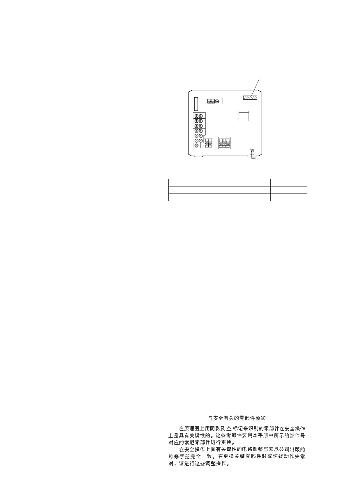
1. SERVICING NOTES
• MODEL IDENTIFICATION (Page 3)
– Rear Panel –
PART No.
MODEL PART No.
Malaysia, Singapore and Hong Kong models 4-221-391-5[]
Thai and Chinese models 4-221-391-7[]
SAFETY-RELATED COMPONENT WARNING!!
COMPONENTS IDENTIFIED BY MARK 0 OR DOTTED
LINE WITH MARK 0 ON THE SCHEMATIC DIAGRAMS
AND IN THE PARTS LIST ARE CRITICAL TO SAFE
OPERATION. REPLACE THESE COMPONENTS WITH
SONY PARTS WHOSE PART NUMBERS APPEAR AS
SHOWN IN THIS MANUAL OR IN SUPPLEMENTS PUBLISHED BY SONY.
2
Page 3
2. GENERAL
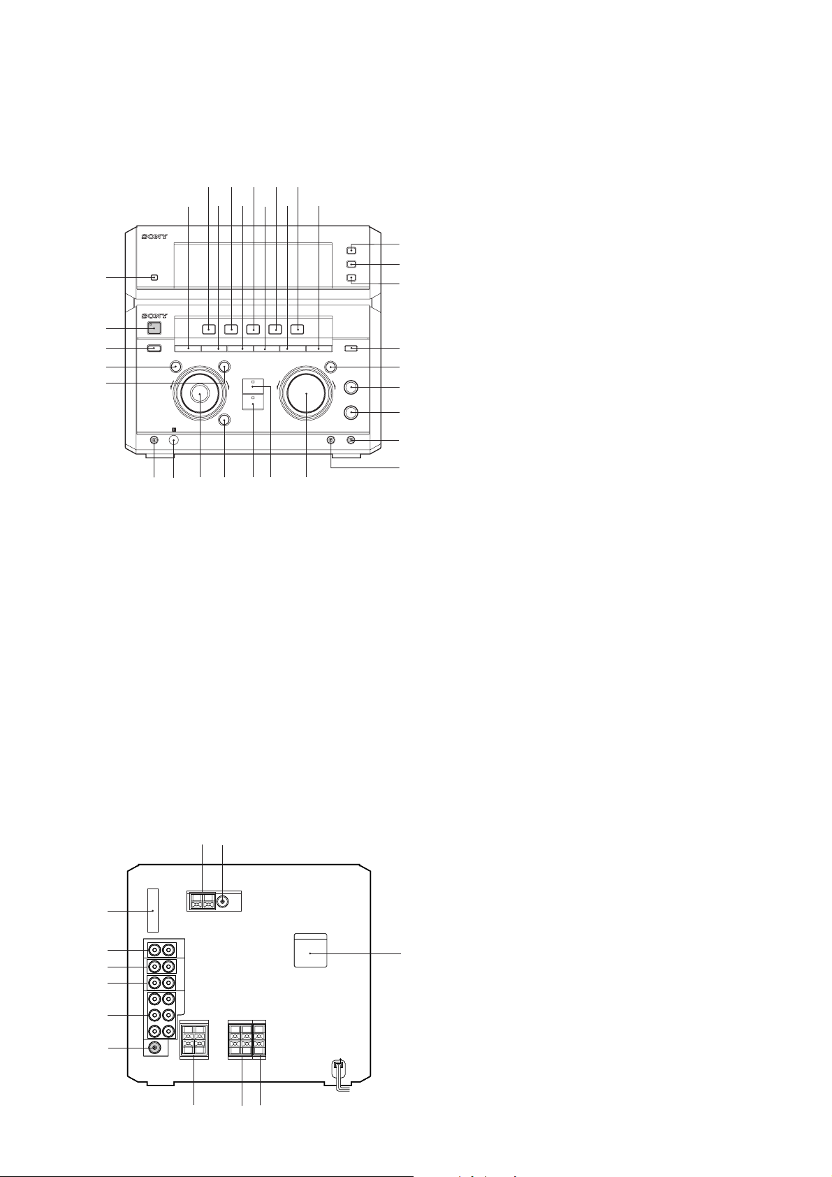
• LOCATION OF CONTROLS (Page 4)
– Front Panel –
1
2
3
4
5
wh
– Rear Panel –
l
wj
9
7
6
–
m
wk
qa qd
08
+
M
>
wl e; ea
qs
qg
qf qh
–
es
1 DISPLAY button
2 ?/1 button and indicator
3 POWER SAVE/DEMO (STANDBY) button
qj
qk
ql
4 – m button
5 + M button
6 FILE SELECT button
7 VIDEO/DVD button
8 EDIT button
9 MD button
w;
wa
+
ws
wd
wf
0 REPEAT button
qa TAPE button
qs PLAY MODE button
qd CD button
qf DBFB button
qg TUNER button
wg
qh DSP button
qj TUNER BAND button
qk STEREO/MONO button
ql TUNER MEMORY button
w; KARAOKE PON button
wa GROOVE button and indicator
ws ECHO LEVEL knob
wd MIC LEVEL knob
wf MIC 1 jack
wg MIC 2 jack
wh PHONES jack
wj Remote sensor
wk Jog dial
wl ENTER button and indicator
e; DVD 5.1CH button and indicator
ea PRO LOGIC button and indicator
es VOLUME knob
3
3
4
4
5
5
6
6
7
7
8
8
0
0
1
212
qa
qa
qs
qs
99
1 AM ANTENNA terminals
2 FM ANTENNA terminal
3 SYSTEM CONTROL connector
4 VIDEO (AUDIO) IN jacks
5 MD IN jacks
6 MD OUT jacks
7 DVD 5.1CH INPUT jacks
8 SUPER WOOFER OUT jack
9 VOLTAGE SELECTOR switch
(Malaysia, Singapore and Hong Kong models)
q; FRONT SPEAKER terminals
qa REAR SPEAKER terminals
qs CENTER SPEAKER terminals
3
Page 4
(Page 5)
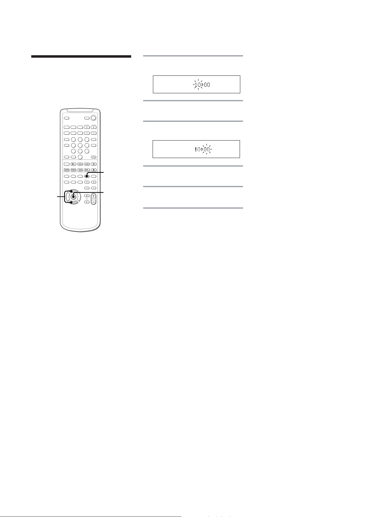
Step 3: Setting the
time
You must set the time before using the timer
functions.
1
1
Press CLOCK/TIMER.
The hour indication flashes.
2
Press V or v repeatedly to set the
hour.
3
Press ENTER.
The minute indication flashes.
4
Press V or v repeatedly to set the
minute.
2,4
V
bB
v
3,5
5
Press ENTER.
The clock starts working.
Tips
• If you make a mistake, start over from step 1.
• Setting the time deactivates the demo mode.
If you want to display the demo mode, press
DEMO (STANDBY) when the power is off.
To change the time
The previous explanation shows how to set
the time while the power is off. To change the
time while the power is on, do the following:
1 Press CLOCK/TIMER.
2 Press V or v repeatedly to select the SET
CLOCK.
3 Press ENTER.
4 Perform steps 2 through 5 above.
Note
The clock settings are cancelled when you
disconnect the mains lead or if a power failure
occurs.
10
4
Page 5
3. DIAGRAMS
3-1. IC PIN FUNCTION DESCRIPTION (Page 24, 25)
(STR-NX1/NX3)
• MAIN BOARD IC501 M30622MA-A12FP (SYSTEM CONTROLLER )
Pin No. Pin Name I/O
Key input terminal (A/D input)
93 KEY1 I
(STR-NX300)
• MAIN BOARD IC501 M30622MA-A29FP (SYSTEM CONTROLLER )
Pin No. Pin Name I/O
93 KEY1 I
S615 to S617, S619 to S624 (TUNER BAND, STEREO/MONO, TUNER MEMORY,
GROOVE, + M, – m, ENTER, DVD 5.1CH, PRO LOGIC) keys input
(S623 DVD 5.1CH, S624 PRO LOGIC keys: used for the STR-NX3 only)
Key input terminal (A/D input)
S615 to S624 (TUNER BAND, STEREO/MONO, TUNER MEMORY, KARAOKE PON,
GROOVE, + M, – m, ENTER, DVD 5.1CH, PRO LOGIC) keys input
Description
Description
5
Page 6

STR-NX300
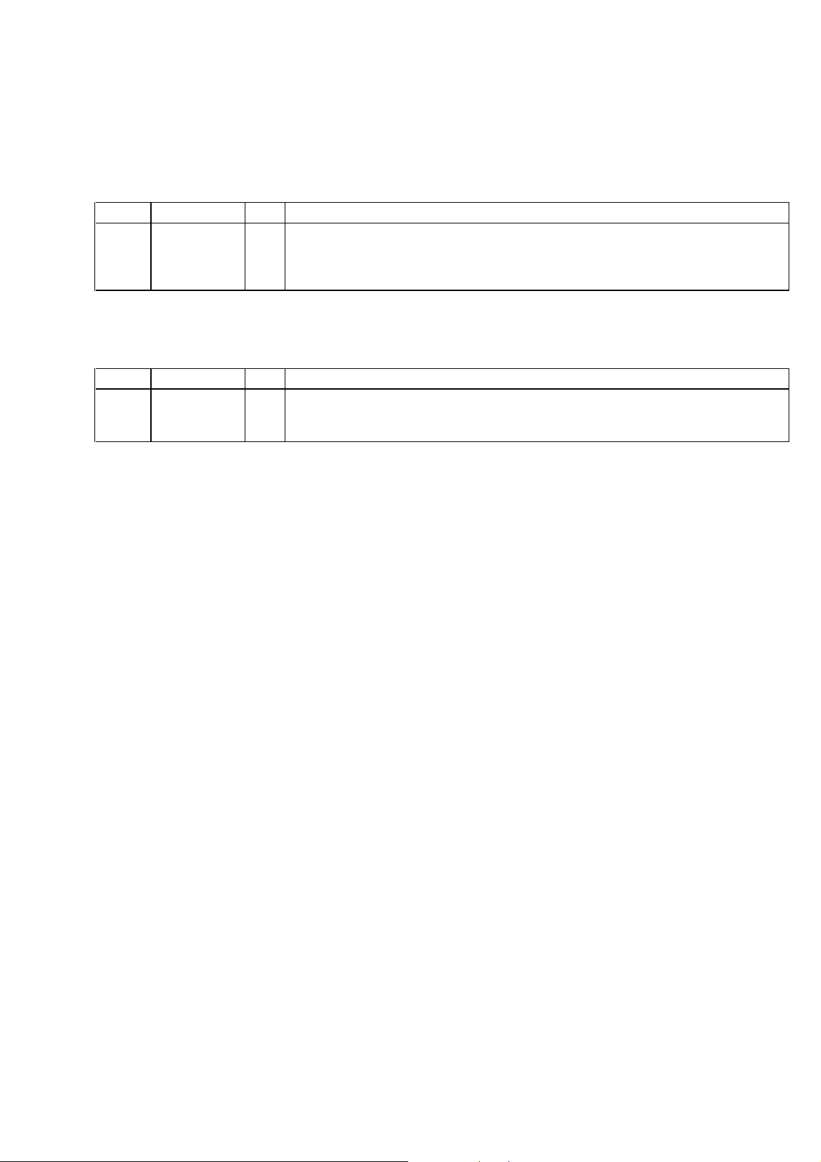
3-2. PRINTED WIRING BOARD – MAIN Board –
! : Difference portion.
Page STR-NX1/NX3 STR-NX300
Location C – D, 6 – 8
#
(MY, SP, HK, CH)
Location D – G, 2 – 5
15
(TH, CH)
@
R540
R541
CN191
10 1
(FOR TEST)
(CH)
#
(CH)
R526
%
R529
$
(CH)
(CH)
(CH)
$
• Abbreviation
CH : Chinese model
HK : Hong Kong model
MY : Malaysia model
SP : Singapore model
TH : Thai model
6
Page 7

3-3. SCHEMATIC DIAGRAM – MAIN Board (2/3) – (Page 13)
! : Difference portion.
STR-NX300
$
#
!
#
^
• Abbreviation
CH : Chinese model
HK : Hong Kong model
77
MY : Malaysia model
SP : Singapore model
TH : Thai model
Page 8

STR-NX300
3-4. SCHEMATIC DIAGRAM – PA Board –
! : Difference portion.
Page STR-NX1/NX3 STR-NX300
Location A – D, 9 – 12
19
!
#
3-5. PRINTED WIRING BOARD – PANEL Board –
! : Difference portion.
Page STR-NX1/NX3 STR-NX300
Location D – E, 1
S618
KARAOKE
PON
Location F – G, 1 – 4
20
^
C704
R701
R715
R702
R711
C727
16
1
@
IC702
C721
C723
R713
C734
R714
D701
R712
C735
R718
C732
9
C729
C731
C728
8
R716
C722
C724
C725
R721
C726
R717
@
#
88
Page 9

3-6. SCHEMATIC DIAGRAM – PANEL Board – (Page 21)
! : Difference portion.
STR-NX300
^
%
!
!
$
IC702 M65850FP
VCC
1/2 VCC
AUTO
RESET
CLOCK
OSCILLATOR
CLOCK
RESET
CONTROL
D1
REF
MAIN
DO0
DO1
OP2IN
D/A
MO
MI
OP2OUT
LPF2IN
20KBIT
LPF2OUT
891014 13 12 11
LPF2
SRAM
LPF1
2 345 6 7
1
LPF1IN
LPF1OUT
A/D
OP1IN
OP1OUT
CC1
CC2
GND
99
Page 10

STR-NX300
65
68
62
68
64
66
67
63
not
supplied
S
(
3-7. PRINTED WIRING BOARD AND SCHEMATIC DIAGRAM – TRANS Board –
! : Difference portion.
Page STR-NX1/NX3 STR-NX300
(MY,
JW953
@
22
Location A – D, 5 – 7
#
(TH, CH)
(MY, SP, HK)
$
4. EXPLODED VIEWS
• Abbreviation
CH : Chinese model
HK : Hong Kong model
MY : Malaysia model
SP : Singapore model
TH : Thai model
Page STR-NX1/NX3 STR-NX300
Ref. No. Part No. Description Remark
3 X-4952-296-1 PANEL ASSY, BACK (NX3: MY, SP)
4 1-733-011-11 WIRE (FLAT TYPE) (15CORE)
26
6 1-233-546-11 TUNER PACK (FM/MW/SW) (MY, SP)
65
• Items marked “*” are not stocked since they
are seldom required for routine service. Some
delay should be anticipated when ordering
these items.
Ref. No. Part No. Description Remark
3 X-4952-296-1 PANEL ASSY, BACK (MY, SP, HK)
3 X-4952-356-1 PANEL ASSY, BACK (CH, TH)
4 1-751-688-11 WIRE (FLAT TYPE) (13CORE) (TH)
(AEP, UK, MY, SP, JE)
4 1-733-011-11 WIRE (FLAT TYPE) (15CORE)
6 1-233-545-11 TUNER PACK (FM/MW/SW) (TH)
6 1-233-546-11 TUNER PACK (FM/MW/SW) (MY, SP, HK)
6 1-693-381-11 TUNER PACK (FM/MW/SW) (CH)
The components identified by
mark 0 or dotted line with mark
0 are critical for safety.
Replace only with part number
specified.
(MY, SP, HK)
23
68
62
68
^
(
TH, CH)
(
MY, SP, HK)
@
27
53 X-4951-816-1 PANEL ASSY, FRONT (NX3: E, AUS)
65 A-4426-275-A PANEL BOARD, COMPLETE (NX3: E, AUS)
67 1-769-886-11 WIRE (FLAT TYPE) (7CORE)
63
not
supplied
67
64
66
53 X-4952-015-2 PANEL ASSY, FRONT
65 A-4426-655-A PANEL BOARD, COMPLETE
67 1-769-885-11 WIRE (FLAT TYPE) (7CORE)
#
• Abbreviation
CH : Chinese model
HK : Hong Kong model
MY : Malaysia model
The components identified by mark 0 or dotted
line with mark 0 are critical for safety.
Replace only with part number specified.
SP : Singapore model
TH : Thai model
1010
Page 11

Page STR-NX1/NX3 STR-NX300
not
supplied
#5
#2
105
A
Ref. No. Part No. Description Remark
29
102 A-4426-281-A PA BOARD, COMPLETE (NX3: E, AUS)
0 104 1-575-651-11 CORD, POWER (NX: MY, SP)
* 105 3-703-244-00 BUSHING (2104), CORD
106 A-4426-277-A MAIN BORD, COMPLETE (NX3: MY, SP)
109 4-221-364-01 CHASSIS
0 T951 1-433-996-11 TRANSFORMER, POWER (NX3: E, AUS)
(US, CND, AEP, UK, KR, MY, SP, AUS)
supplied
#5
#2
102
105
A
Ref. No. Part No. Description Remark
102 A-4428-730-A PA BOARD, COMPLETE
0 104 1-777-071-51 CORD, POWER (HK, MY, SP)
0 104 1-783-205-11 CORD, POWER (CH)
0 104 1-791-901-11 CORD, POWER (TH)
* 105 3-703-244-21 BUSHING (2104), CORD (MY, SP, HK, CH)
* 105 3-703-571-11 BUSHING (S) (4516), CORD (TH)
106 A-4426-657-A MAIN BORD, COMPLETE (MY, SP, HK)
106 A-4428-007-A MAIN BORD, COMPLETE (CH)
106 A-4428-364-A MAIN BORD, COMPLETE (TH)
0 107 1-770-019-11 ADAPTOR, CONVERSION 2P (HK)
109 X-4952-635-1 CHASSIS ASSY
0 T951 1-435-279-11 TRANSFORMER, POWER
#5
102
The components identified by
mark 0 or dotted line with
mark 0 are critical for safety.
Replace only with part number specified.
11
Page 12

5. ELECTRICAL PARTS LIST
• Abbreviation
CH : Chinese model
HK : Hong Kong model
MY : Malaysia model
SP : Singapore model
TH : Thai model
Page STR-NX1/NX3 STR-NX300
30
A-4426-277-A MAIN BOARD, COMPLETE (NX3: MY, SP)
*********************
• Items marked “*” are not stocked since they
are seldom required for routine service.
Some delay should be anticipated when ordering these items.
Ref. No. Part No. Description RemarkRef. No. Part No. Description Remark
A-4426-657-A MAIN BOARD, COMPLETE (MY, SP, HK)
A-4428-007-A MAIN BOARD, COMPLETE (CH)
A-4428-364-A MAIN BOARD, COMPLETE (TH)
The components identified by
mark 0 or dotted line with mark
0 are critical for safety.
Replace only with part number
specified.
When indicating parts by reference
number, please include the board.
*********************
32
35
36
CN121 1-784-776-11 CONNECTOR, FFC 15P
(AEP, UK, MY, SP, JE)
IC501 8-759-597-56 IC M30622MA-A12FP
R582 1-249-407-11 CARBON 150 5% 1/4W
(NX3)
R584 1-249-417-11 CARBON 1K 5% 1/4W
(MY, SP, JE)
A-4426-281-A PA BOARD, COMPLETE (NX3: E, AUS)
*******************
C883 1-127-813-11 ELECT 3300uF 20% 71V
(E, AUS, JE)
C884 1-127-813-11 ELECT 3300uF 20% 71V
(E, AUS, JE)
CN121 1-784-774-11 CONNECTOR, FFC 13P (TH)
CN121 1-784-776-11 CONNECTOR, FFC 15P (MY, SP, HK, CH)
IC501 8-759-656-80 IC M30622MA-A29FP
R582 1-249-415-11 CARBON 680 5% 1/4W
R583 1-249-425-11 CARBON 4.7K 5% 1/4W
(TH, CH)
R584 1-249-411-11 CARBON 330 5% 1/4W
(TH)
R584 1-249-415-11 CARBON 680 5% 1/4W
(CH)
R584 1-249-417-11 CARBON 1K 5% 1/4W
(MY, SP, HK)
A-4428-730-A PA BOARD, COMPLETE
*******************
C883 1-127-812-11 ELECT 3300uF 20% 63V
C884 1-127-812-11 ELECT 3300uF 20% 63V
12
Page 13

Page STR-NX1/NX3 STR-NX300
Ref. No. Part No. Description Remark
Ref. No. Part No. Description Remark
39
A-4426-275-A PANEL BOARD, COMPLETE (NX3: E, AUS)
**********************
C714 1-162-282-31 CERAMIC 100PF 10% 50V
A-4426-655-A PANEL BOARD, COMPLETE
**********************
C704 1-162-306-11 CERAMIC 0.01uF 30% 16V
C705 1-126-961-11 ELECT 2.2uF 20% 50V
C714 1-162-284-31 CERAMIC 150PF 10% 50V
C721 1-162-294-31 CERAMIC 0.001uF 10% 50V
C722 1-162-305-11 CERAMIC 0.0068uF30% 16V
C723 1-126-960-11 ELECT 1uF 20% 50V
C724 1-136-495-11 MYLAR 0.068uF 5% 50V
C725 1-126-959-11 ELECT 0.47uF 20% 50V
C726 1-126-959-11 ELECT 0.47uF 20% 50V
C727 1-136-167-00 MYLAR 0.15uF 5% 50V
C728 1-162-294-31 CERAMIC 0.001uF 10% 50V
C729 1-126-960-11 ELECT 1uF 20% 50V
C730 1-161-494-00 CERAMIC 0.022uF 25V
C731 1-162-305-11 CERAMIC 0.0068uF30% 16V
C732 1-136-495-11 MYLAR 0.068uF 5% 50V
C733 1-104-664-11 ELECT 47uF 20% 16V
C734 1-164-159-11 CERAMIC 0.1uF 50V
C735 1-104-664-11 ELECT 47uF 20% 16V
C736 1-126-961-11 ELECT 2.2uF 20% 50V
D701 8-719-109-85 DIODE MTZJ-T-72-5.1B
R707 1-249-433-11 CARBON 22K 5% 1/4W
40
0 F951 1-533-949-31 FUSE T8AL/250V (NX3: MY, SP)
0S951 1-771-291-11 SWITCH, POWER (VOLTAGE SELECTOR)
41
0 T951 1-433-996-11 TRANSSFORMER, POWER (NX3: E AUS)
(MY, SP, JE)
J703 1-785-569-11 JACK (SMALL TYPE) (MIC 2)
IC702 8-759-496-40 IC M65850FP
R701 1-249-429-11 CARBON 10K 5% 1/4W
R702 1-249-417-11 CARBON 1K 5% 1/4W
R707 1-249-437-11 CARBON 47K 5% 1/4W
R711 1-249-433-11 CARBON 22K 5% 1/4W
R712 1-249-401-11 CARBON 47 5% 1/4W
R713 1-249-433-11 CARBON 22K 5% 1/4W
R714 1-249-433-11 CARBON 22K 5% 1/4W
R715 1-249-437-11 CARBON 47K 5% 1/4W
R716 1-249-433-11 CARBON 22K 5% 1/4W
R717 1-249-433-11 CARBON 22K 5% 1/4W
R718 1-247-881-00 CARBON 120K 5% 1/4W
R719 1-249-431-11 CARBON 15K 5% 1/4W
R720 1-249-431-11 CARBON 15K 5% 1/4W
R721 1-249-433-11 CARBON 22K 5% 1/4W
S618 1-762-875-21 SWITCH, KEYBOARD (KARAOKE PON)
RV702 1-225-739-11 RES, VAR CARBON 50K (ECHO LEVEL)
0 F951 1-532-505-31 FUSE T5AL/250V (MY, SP, HK)
0 S951 1-771-291-11 SWITCH, POWER (VOLTAGE SELECTOR)
(MY, SP, HK)
0 T951 1-435-279-11 TRANSSFORMER, POWER
The components identified by
mark 0 or dotted line with
mark 0 are critical for safety.
Replace only with part number specified.
13
Page 14

STR-NX300
Page STR-NX1/NX3 STR-NX300
Ref. No. Part No. Description RemarkRef. No. Part No. Description Remark
MISCELLANEOUS
**************
MISCELLANEOUS
**************
4 1-733-011-11 WIRE (FLAT TYPE) (15CORE)
6 1-233-546-11 TUNER PACK (FM/MW/SW) (MY, SP)
41
67 1-769-886-11 WIRE (FLAT TYPE) (7CORE)
0 104 1-575-651-11 CORD, POWER (NX3: MY, SP)
0 T951 1-433-996-11 TRANSFORMER, POWER (NX3: E, AUS)
(AEP, UK, MY, SP, JE)
4 1-751-688-11 WIRE (FLAT TYPE) (13CORE) (TH)
4 1-733-011-11 WIRE (FLAT TYPE) (15CORE)
6 1-233-545-11 TUNER PACK (FM/MW/SW) (TH)
6 1-233-546-11 TUNER PACK (FM/MW/SW) (MY, SP, HK)
6 1-693-381-11 TUNER PACK (FM/MW/SW) (CH)
67 1-769-885-11 WIRE (FLAT TYPE) (7CORE)
0 104 1-777-071-51 CORD, POWER (HK, MY, SP)
0 104 1-783-205-11 CORD, POWER (CH)
0 104 1-791-901-11 CORD, POWER (TH)
0 107 1-770-019-11 ADAPTOR, CONVERSION 2P (HK)
0 T951 1-435-279-11 TRANSFORMER, POWER
The components identified by
mark 0 or dotted line with
mark 0 are critical for safety.
Replace only with part number specified.
(MY, SP, HK)
9-929-045-11
14
Sony Corporation
Home Audio Division Company
Printed in Singapore C 2000. 1
2000A0570082-1
Published by Quality Assurance Dept.
 Loading...