

Sony STR-K9900P, HT-9900M, HT-6900DP Owner’s Manual
SON_
2-549-736-11(1)
DVD Home
Theatre System
Operating Instructions
Owner's Record
The model and serial numbers are located on the rear of the unit. Record the serial
number in the space provided below. Refer to them whenever you call upon your
Sony dealer regarding this product.
Model No. Serial No.
HT-9900M
HT-6900DP
HT-5950DP
@2005 Sony Corporation
To prevent fire or shock hazard, do not
expose the unit to rain or moisture.
To prc_ ent fire, do not cover the _ entihttion of the
apparatus with newspapers, table-cloths, curtains, etc.
And don_t place lighted candles on the apparatus.
To prevent fire or shock hazard, do not place objects
filled with liquids, such as vases, on Ihe apparatus.
Do nol install Ihe appliance in a confined space,
such as a bookcase or buill-in cabinet.
Don't throw away batteries with
general house waste; dispose of
them correctly aschemica] waste.
For customers in the United States
This symbol is intended to alert
Ihe user to the presence of
uninsulatcd "dangerous voltage"
within the product's enclosure
that may be of sufficient
magnitude to constitute a risk of
electric shock to persons.
This symbol is intended to alert
the user to the presence of
important operating and
maintenance (servicing)
instructions in the literature
accompanying the appliance.
WARNING
This equipment has been tested and found to comply
with the limits for a Class B digital device, pursuant to
Part 15 of the FCC Rules. These limits are designed to
provide re ,sonable protection against harmful
interlk:rence in a residential installation. This
equipment generates, uses, and can radiate r,dio
frequency energy and, if not inst dled and used in
accordance with the instructions, may cause harmfid
interference to radio communications. However, there
is no guarantee that interference will not occur in
particular installation. If this equipment does cause
harmfid interlk:rence to radio or televiskm reception,
which can be determined by turning the equipment off
and on, the user is encouraged to try to com:ct the
interference by one or more of the following measures:
Reorient or relocate the receiving antenna.
Increase the separation between the equipment and
receiver.
Connect the equipment into an outlet on a circuit
different from that to which the receiver is
connected.
Consult the dealer or an experienced radio_V
technician for help.
CAUTION
You arc cautkmed that any changes or modificatkm not
expressly approved in this manual could void your
authority to operate this equipment.
Note to CATV system installer:
This reminder is pro_ided to call CATV system
installer's attention to Article 820-40 of the NEC that
provides guidelines R)rproper grounding and, in
particular, specifies that the cable ground shall be
connected to the grounding system of the building, as
close to the point of cable entry as practicah
For customers in Canada
CAUTION
TO PREVENT ELECTRIC SHOCK, MATCH WIDE
BLADE OF PLUG TO WIDE SLOT, FULLY
INSERT.
ENERGY STAR/'>is a U.S. registered
mark. As an ENERGY STAR/_/pallner,
Sony Corporation has determined that
Ihis product meets Ihe ENERGY STAR<_
guidelines for energy efficiency.
2 us
About This Manual
• The instructions in this manual arc lbr model
HT-9900M, HT-6900DP and HT-5950DP. Check
your receiver's model nmnber by looking at the
lower right corner of the front panel. In this manual,
HT-9900M is used for illustration purposes unless
stated other_ ise. Any difference in operation is
clearly indicated in the text, lbr example, "HT-
9900M only"
• The instructions in this manual describe the controls
on the receiver. You can also use the controls on the
supplied remote if they have the same or similar
names as those on the receiver. For details on the use
of your remote, see pages 43 51. For details on the
use of your DVD player, refer to the separate
operating instructions supplied _ilh the DVD player.
The HT-9900M consists of:
• Receiver STR K9900P
• Speaker system
Front speaker (left) SS MSP69L
Front speaker (right) SS MSP69R
Center speaker SS CNP69
Surround speaker (left) SS MSP69SL
Surround speaker (right) SS MSP69SR
Surround back speaker SS MSP69SB
Sub woofer SA-WMSP69
• DVD player DVP-CX985V
The HT-6900DP consists of:
• Receiver STR K9900P
• Speaker system
Front speaker (left) SS MSP69L
Front speaker (right) SS MSP69R
Center speaker SS-CNP69
Surround speaker (left) SS-MSP69SL
Surround speaker (right) SS-MSP69SR
Surround back speaker SS-MSP69SB
Sub woofer SA-WMSP69
• DVD player DVP-NC60P
The HT-5950DP consists of:
• Receiw:r STR-K5900P
• Speaker system
Front speaker (left) SS-MSP67L
Front speaker (right) SS-MSP67R
Center speaker SS-CNP67
Surround speaker (left) SS-MSP67SL
Surround speaker (right) SS-MSP67SR
Surround back speaker SS-MSP67SB
Sub woofer SA-WMSP87
• DVD player DVP-NC60P
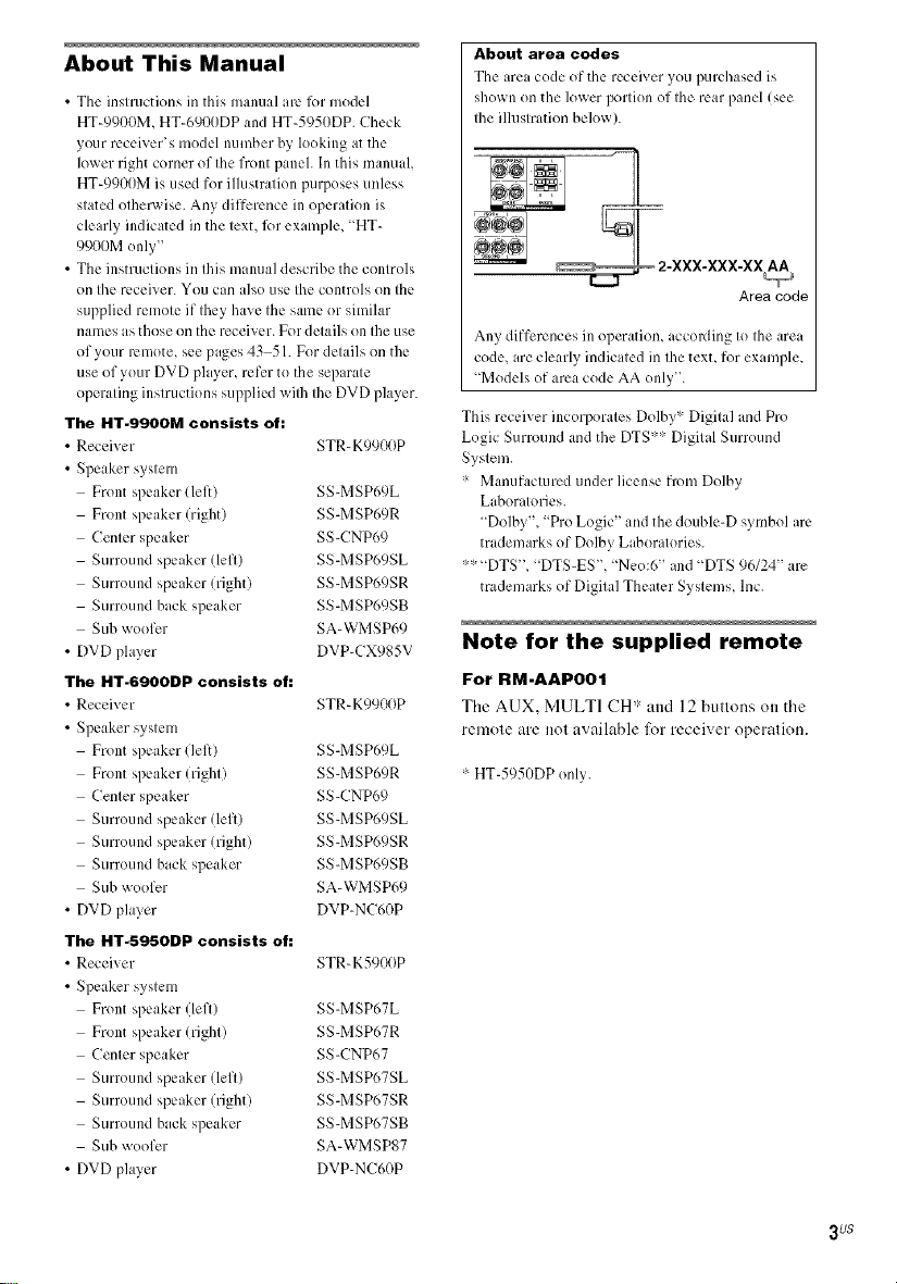
About area codes
The area code of the receiver youpurchased is
shown on the lower portion of the rear panel (see
the ilhlstration below).
Areacode
Any differences in operation, accoaling to the area
code, are clearly indicated in the text, for example,
"Modelsof area code AA only".
This receiver incorporates Dolby* Digital and Pro
Logic Surround and the DTS** Digital Surround
System.
:- Manufactured under license from Dolby
Laboratories.
"Dolby", "Pro Logic" and the double-D symbol are
trademarks of Dolby Laboratories.
:'-:_"DTS', "DTS-ES', "Neo:6" and "DTS 96124" are
trademarks of Digital Theater Systems, lnc.
Note for the supplied remote
For RM-AAP001
The AUX, MULTI CH* and 12 buttons on the
remote are not available tbr receiver operation.
:-HT-5950DP only.
3us
Getting Started
1: Check how to hookup your
components ....................................... 5
I a: Connecting components with
digital audio output jacks ........... 7
I b: Connecting components with
nmlti channel output jacks ........ 10
lc: Connecting components with
only analog audio jacks ............ 12
2: Connecting the antennas ................... 14
3: Connecting speakers ......................... 15
4: Connecting the AC power cord ........ 17
5: Setting up the speakers ..................... 19
6: Setting up the sub woofer ................. 21
7: Adjusting the speaker levels and
balance ............................................ 22
-- TEST TONE
Amplifier Operation
Selecting tile component ....................... 23
Listening to multi channel sound .......... 24
-- MULTI CH IN
Listening to FM/AM radio .................... 24
Presetting radio stations ........................ 25
Changing the display ............................. 26
About the indications in the display ...... 27
Enjoying Surround Sound
Using only tile front speakers and
sub woofer ...................................... 29
-- 2CH STEREO
Enjoying higher fidelity sound .............. 29
-- AUTO FORMAT DIRECT
Selecting a sound field .......................... 31
Selecting the surround back decoding
mode ............................................... 33
SURR BACK DECODING
Advanced Adjustments and
Settings
Assigning the component video
input ................................................ 35
COMPONENT VIDEO
INPUT ASSIGN
Switching the audio input mode for
digital components ......................... 35
-- INPUT MODE
Customizing sound fields ..................... 36
Adjusting the tone ................................. 37
Advanced settings ................................. 38
Other Operations
Naming preset stations and inputs ........ 40
Using the Sleep Timer .......................... 40
Selecting the speaker system ................ 41
Recording ............................................. 41
Operations Using the Remote
RM-AAP001
Before you use your remote .................. 43
Remote button description .................... 43
Selecting the command mode of the
remote ............................................. 47
Programming the remote ...................... 48
Additional Information
Precautions ........................................... 52
Troubleshooting .................................... 53
Specifications ....................................... 55
List of button locations and reference
pages ............................................... 59
Index ........................................ back cover
4 US
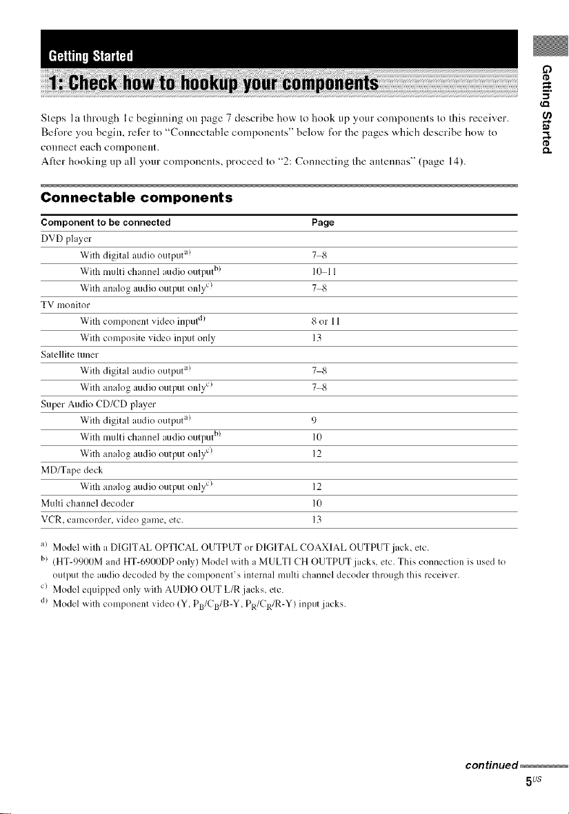
Steps l a through l c beginning on page 7 describe how to hook up your components to this receiver.
Bel;,_re you hegin, reli:r to "Connectable components" below l\_r tile pages which describe how to
COIlnect each compollellt.
Alter booking up all your components, proceed to "2: Connecting the antennas" (page 14).
Connectable components
Component to be connected Page
DVD player
With digital audio output a! 7 8
With multi channel audio output b) 10 11
With analog audio output only c) 7 8
TV monitor
With component video inpul d) 8 or 11
With composite vide() input only 13
Satellite tuner
With digital audio output a! 7 8
With analog audio output only c) 7 8
Super Audio CD/CD player
With digital audio output a! 9
With multi channel audio output b) 10
With analog audio output only c) 12
MD/Tape deck
With analog audio output only c) 12
Multi channel decoder l0
VCR_ camcorder_ video game_ etc. 13
if)
¢D
_=.
¢D
a> Model with a DIGITAL OPTICAL OUTPUT or DIGITAL COAXIAL OUTPUT jack, etc.
b> (HT-9900M and HT-690IIDP only) Model with a MULTI CH OUTPUT jacks, etc. This connection is used to
output the audio decoded by the component' s internal multi channel decoder through this receiver.
c) Model equipped only with AUDIO OUT L/R jacks, etc.
d) Model x_ith component video (Y. PB/CB/B-Y. PR/CR/R-Y) input jacks.
continued
5us
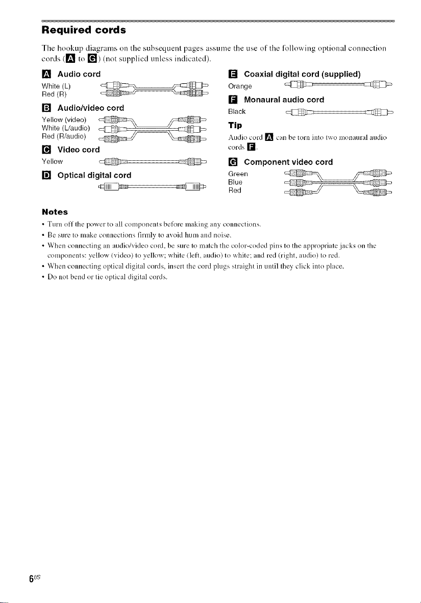
Required cords
The hookup diagrams on the subsequent pages assume the use of the lollowing optional connection
cords ([] to r_) (not supplied unless indicated)
[] Audio cord
White (L)
Red (R)
[] Audio/video cord
White (Uaudio)
Yellow (video)
Red (R/audio)
[] Video cord
Yellow _:IC_1_7 @
[] Optical digital cord
Notes
• Turn off the po_er to all comlx)nents bcfort: m_Jking :lny connections
• Be sure to make connections firmly to avoid hum and noise
• When connecting an audio/video cord, be sure to match the color-coded pills to the appropriate jacks on the
components: yellow (video) to yellow; white (lelk, audio) to white; and red (righL audio) to red
• When connecting optical digital cords, insert the cord plugs straight in until they click into place
• Do not bend or tie optical digital cords
[] Coaxial digital cord (supplied)
Orange @
[] Monaural audio cord
Black _:IZ1_[1:_
Tip
Audio cord [] can be torn into t_o monaural audio
cords r'-J
[] Component video cord
Green
Blue
Red
6 US
g)
tD
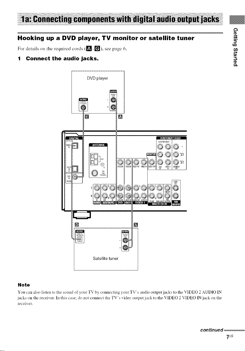
Hooking up a DVD player, TV monitor or satellite tuner -=.
¢Q
For delails o,, the required cords ([_ r_), see page 6.
1 Connect the audio jacks, a
DVD player
tD
[]
OPTIC
B
IN
[]
Satellite tuner _1
Note
Yeu can also listen to the sound of your TV by connecting your TV's audio output jacks to the VIDEO 2 AUDIO IN
jacks on the receiver. In this case. do net connect the TV's video eutput jack to the VIDEO 2 VIDEO INjack on the
receiver.
continued
7us
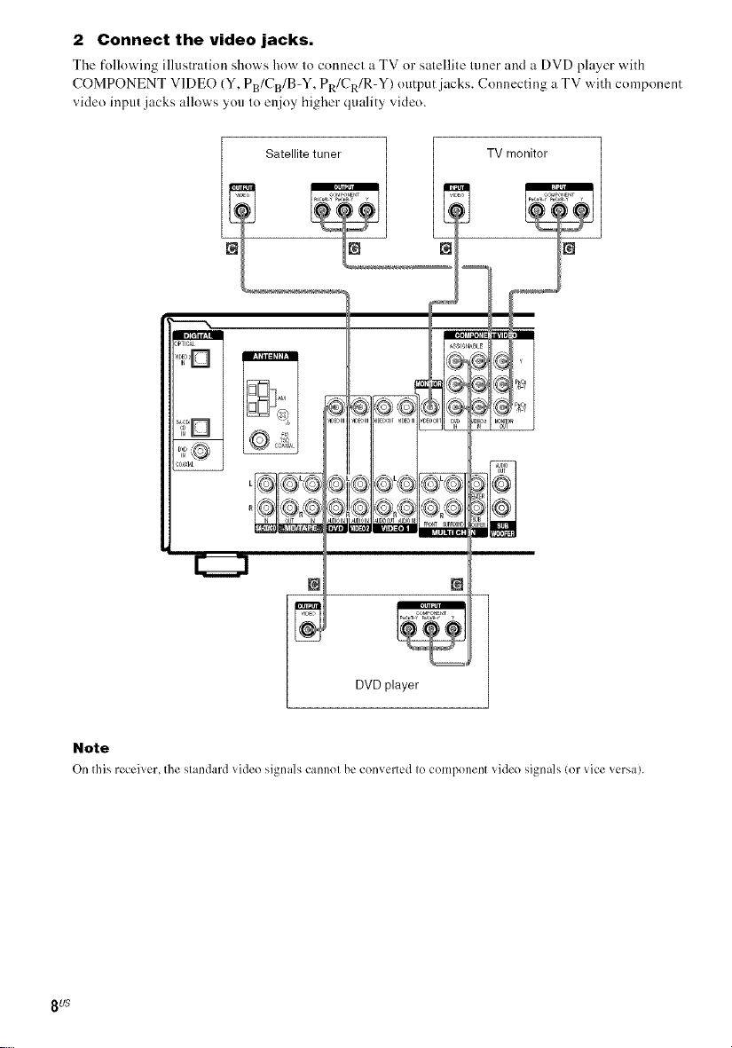
2 Connect the video jacks.
The following illustration shows how to connect _ TV or s:_tellite tuner mM :_ DVD player with
COMPONENT VIDEO (Y, PB/CB/B-Y, PR/CR/R-Y) otltput jzlcks. Connecting u TV with component
vide() input jacks allows you to enjoy higher quality vide().
_I[ttl_:l|
_PTIC_L
• , _IDEOIN_,'I[,EO®T_IDEOINi
_J
Iol
[22221
Note
On this receher, the slandard _ideo signals cannol be converted Iocomponent _ideo signals (or _ice _ersa).
8u$
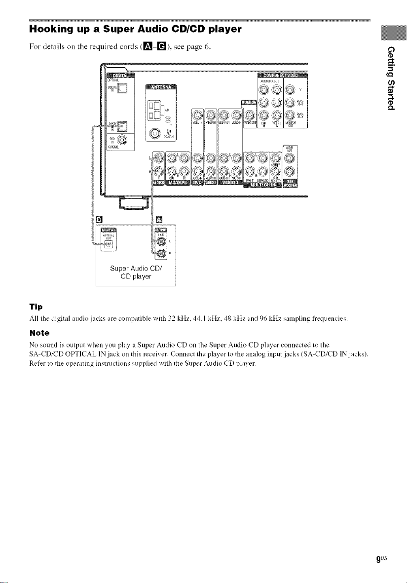
Hooking up a Super Audio CD/CD player
Fordelailson the requiredcords (1_ ["_),see page6.
ASSlC_NAeLE
Tip
All the digital audio jacks are com,:_atiblewith 32 kHz, 44.1 kHz, 48 kHz and 96 kHz sampling frequencies.
Note
No sound ix out,:mt when you play a Su,:_erAudio CD on the Super Audio CD player connected to the
SA-CD/CD OPTICAL IN jack on this receiver. Connect the player to the analog input.jacks (SA-CD/CD IN jacks).
Refer to the operating instructions supplied with the Super Audio CD player.
g)
_=.
-I
9u$
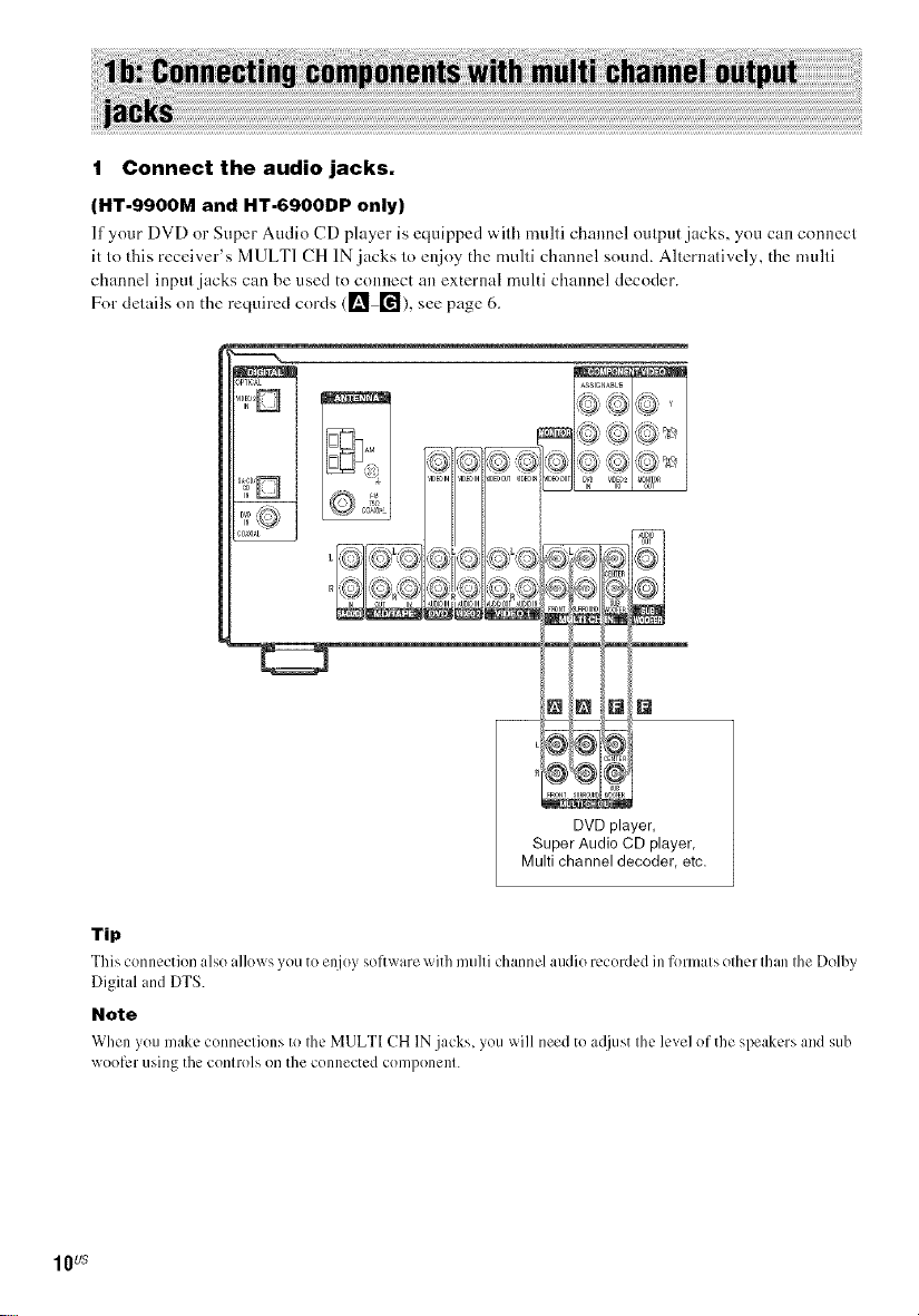
1 Connect the audio jacks.
(HT-9900M and HT-6900DP only)
If your DVD or Super Audio CD player is equipped with multi channel output jacks, you can connect
it to this receiver's MULTI CH IN jacks to enjoy the multi channel sound. Alternatively, the multi
channel input jacks can be used to connect an external multi channel decoder.
For details on the required cords (1_ ["_), see page 6.
_PTICAL
_N NN
DVD player,
Super Audio CD player,
Multi channel decoder, etc.
Tip
This connection also allox_ s you to enjoy sofl_x are with multi channel audio recorded ill formats other than the Dolby
Digital and DTS.
Note
When you make connections to Ihc MULTI CH IN jacks, you _ill need to acljust the level of the speakers and sub
woof_,r using the contro]s on the connected con/ponent.
1Ws
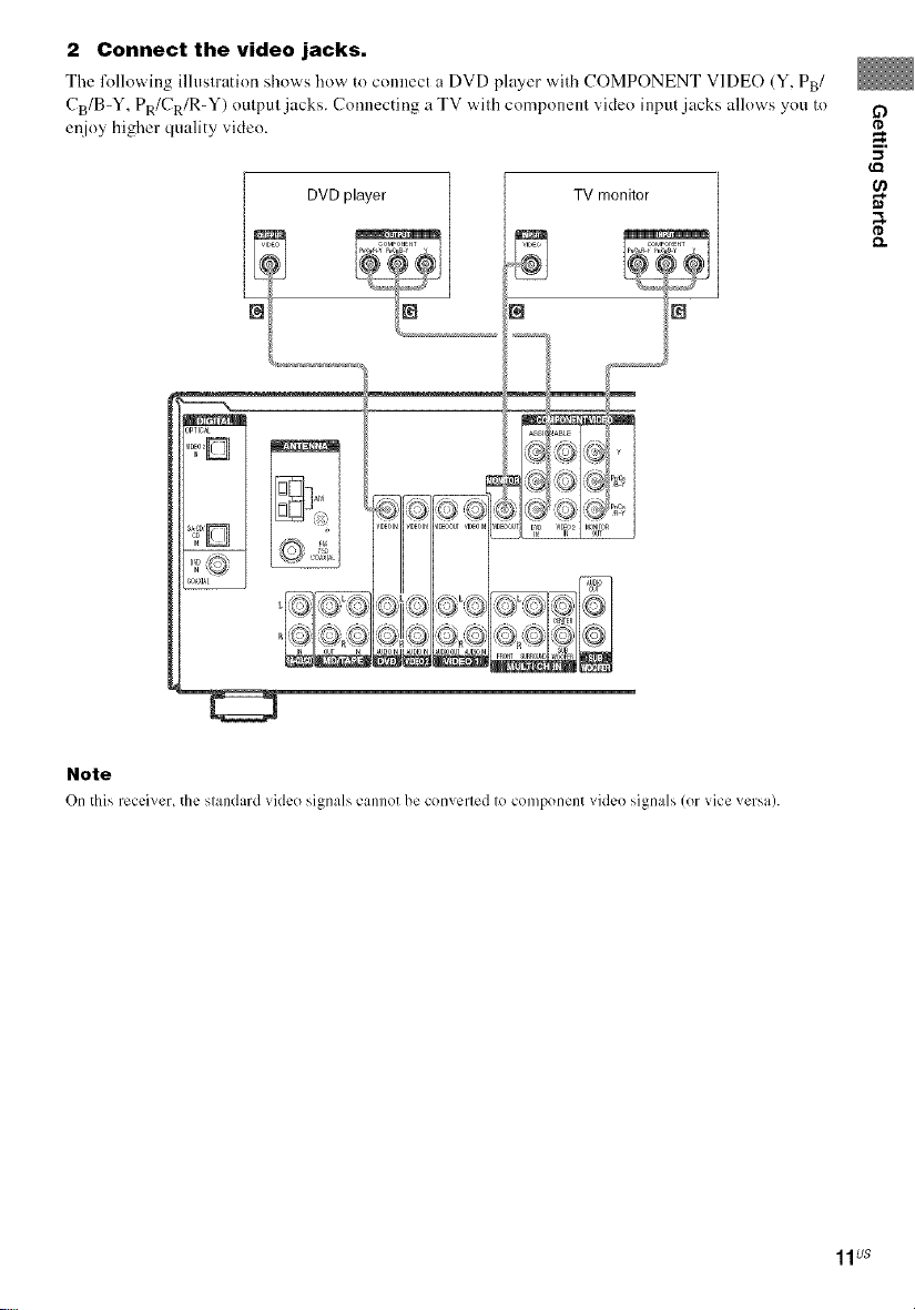
2 Connect the video jacks,
Tile l\_llowing illustration shows how to connect a DVD player with COMPONENT VIDE() (Y, PB/
CB/B-Y, PR/CR/R-Y) output jacks. Connecting a TV with component video input jacks allows you to
enjoy higher quality video.
_g TV monitor
...............
if)
I'D
I'D
Note
On this receiven the standard video signals cannot be converted to component video signals (or vice versa).
11us
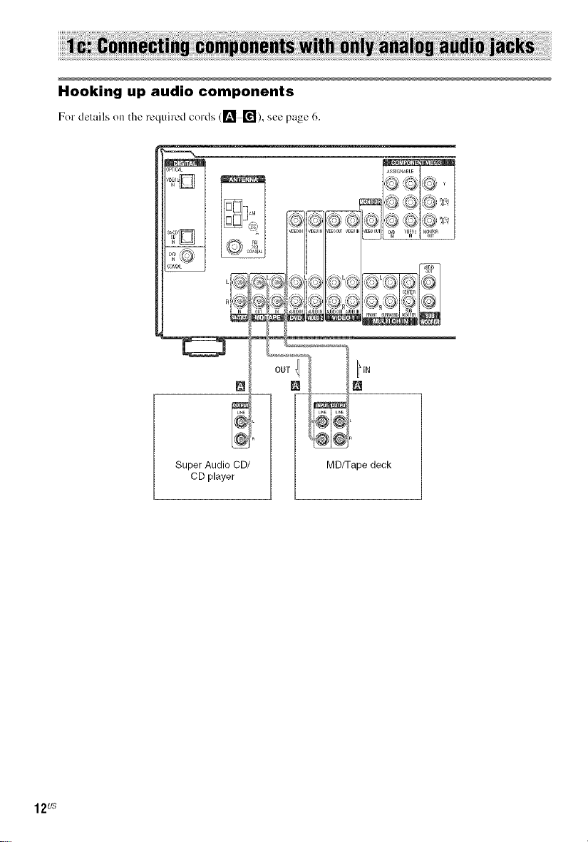
Hooking up audio components
Fordelailsonthe requiredcords (1_ r_), see page6.
12us
Super Audio CD/
CD player
MD/Tape deck
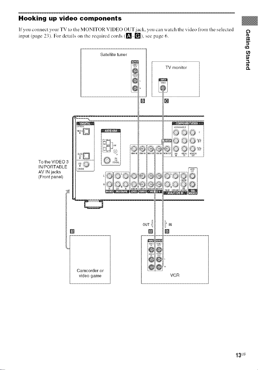
Hooking up video components
If you connect your TV lo tile MONITOR VIDEO OUT jack, you can watch Ihe video h'om ll_e selecled
input (page 23). For delails on Ihe required cords ([] []), see page 6.
Satellite tuner
iV monitor
N
"1
LL__
To the VIDEO 3
IN/PORTABLE
AV IN jacks
(Front panel)
O
I'D
_=.
,,,I
I'D
Camcorder or
video game
OUT {
i
VCR
13us
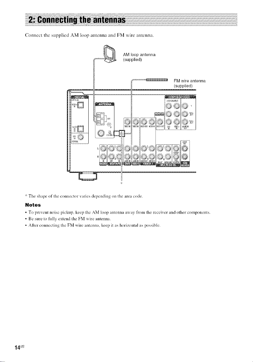
ConnecI Ihe supplied AM loop amenna and FM wire antenna.
_ AM loop antenna
(supplied)
...................._ FM wire antenna
(supplied)
ASSIGNABLE
_:1[__,__ _- >Ls"-,_ s "XL/,o "_
* The shape of the connector varies depending on the area cede
Notes
• To 1)rc_cnt neisc ,:_ickul),keel) the AM 1()%:_antenna a_xayfrem the rccci_ cr and ether cem,:_enents
• Be sure to fully extend the FM wire antenna
• After connecting the FM wire antenna, keep it as horizontal as possible
14us
Connec( your speakers to (he receiver. This receiver allows you to use a 6.1 channel speaker sys(em. ,._
To fully enjoy theater-like mulli channel surround sound requires five speakers (two front speakers, a .,_
center speaker, and two surround speakers) and a sub w'ooti_r (5.1 channel).
You can enjoy high fidelity reproduction of DVD software recorded in the Surround EX lk_rmatif you
connecl one additional surround back speaker (6.1 channel) (see "Selecting the surround back decoding
mode" on page 33). _.
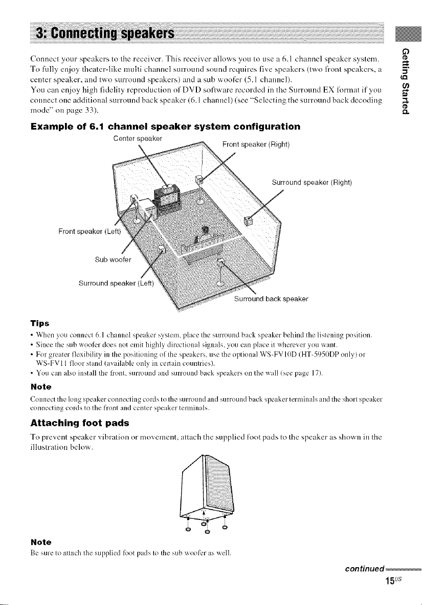
Example of 6.1 channel speaker system configuration
Center speaker
Front speaker (Left)
Sub woofer
Surround speaker (Left)
Tips
• When you connect 6.1 ch mnel speaker system, place the surround back speaker behind the listening position.
• Since the sub weel_.,rdoes not emit highly directional signals, you can place it wherever yeu want.
• Fer greater flexibility in the positioning ef the speakers, use the optional WS-FVIOD (HT-5950DP enly/er
WS-FVI 1fleer stand lavailable only in cellain ceuntries).
• You can also install the l?ent, surround and surround back speakers on the wall lsee page 17).
Note
Connect the long spl:akcr connecting cerds te the surround and surround back speaker terminals and the short speaker
cennecting cerds te the frent and center speaker temfinals.
Attaching foot pads
To prevent speaker _ibration or movement, attach the supplied R)ot pads to the speaker as shown in the
illustration below.
Front speaker (Right)
Surround speaker (Right)
Surround back speaker
if)
m.
I I
o o
Note
Be stue te attach the Sul)pliedlk)etpads le the sub woofer as well.
continued
15us
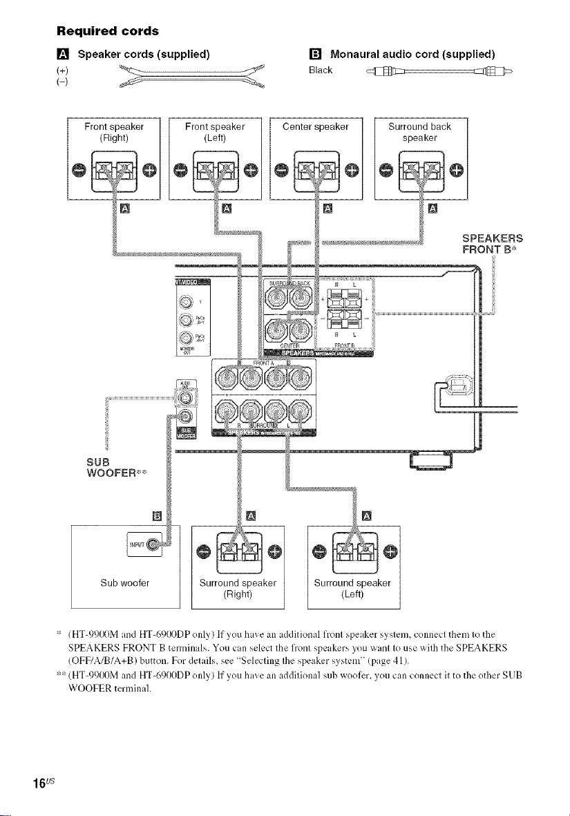
Required cords
[] Speaker cords (supplied) [] Monaural audio cord (supplied)
Black _
Front speaker Front speaker Center speaker Surround back
(Right) (Left) speaker
SPEAKERS
FRONT B*
SUB
WOOFER**
Sub woofer
* (HT-991)0M and HT-6900DP only) If you have an additional front speaker system, connect them to the
SPEAKERS FRONT B terminals. You can select the front speakers you want to use with the SPEAKERS
(OFF/A/B/A+B) button. For details, see Selecting the speaker system" (page 41).
** (HT-991)OM and HT-6900DP only) If you have an additional sub weeler, you can connect it to the ether SUB
WOOFER terminal.
Surround speaker Surround speaker
(Right) (Left)
16us
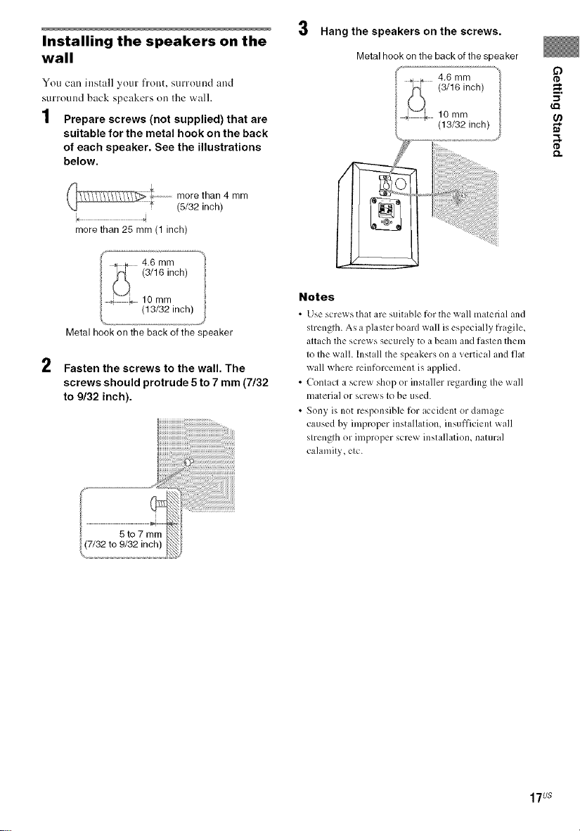
Installing the speakers on the
wall
You can install your front, surround and
surround back speakers on the wall.
1 Prepare screws (not supplied) that are
suitable for the metal hook on the back
of each speaker. See the illustrations
below.
more than 4 mm
,o 4
more than 25 mm (1 inch)
Metal hook onthe back of the speaker
2
Fasten the screws to the wall. The
screws should protrude 5 to 7 mm (7/32
to 9/32 inch).
(5/32 inch)
Hang the speakers on the screws.
Metal hook on the back of the speaker
4,6 mm
(3/16 inch)
10 mm
(13/32 inch)
Notes
• Use scre_ sthat are suitubh.' for the _all material and
strength. As a plaster boaM wall is especi dly fragile,
attach the screws securely to a beam and fasten them
to the wall. Install the speakers on a vertical and flat
wall where reinforcement is applied.
• Contact a screw shop or installer regarding the wall
material or screws to be used.
• Sony is not responsible for accident or damage
caused by improper installation, insufficient wall
strength or improper screw installation, natural
calamity, etc.
o
_=.
_Q
17us
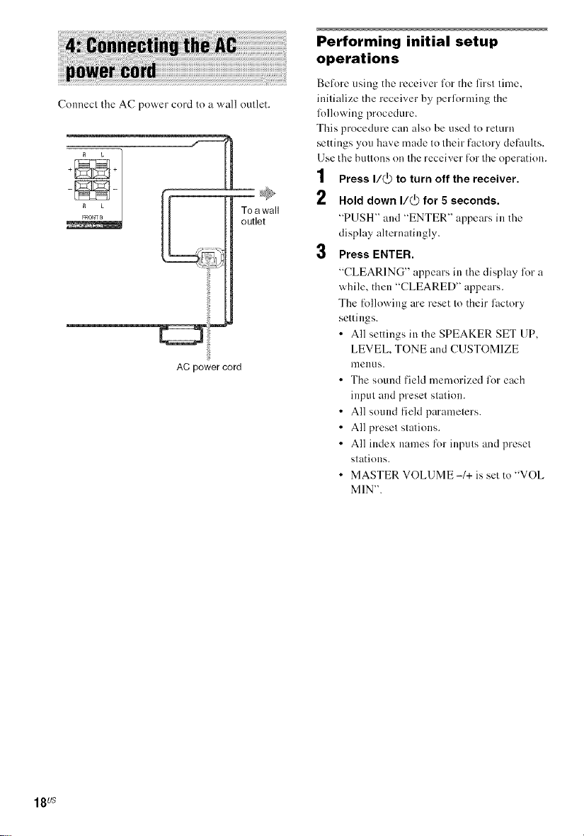
Connect t|_e AC power cord to a wall omlet.
£L
FRONTB
AC power cord
To awall
outlet
Performing initial setup
operations
Before using tile receiver for the firsl lime,
inilialize the receiver by pedkwming the
lk)llowing procedure.
This procedure can also be used lo relurn
settings you have made Io lheir faclory defaults.
Use the butlons on the receiver for ll_e operation.
1 Press I/@ to turn off the receiver.
2 Hold down I/(_ for 5 seconds.
"PUSH' and "ENTER' appears in the
display allernalingly.
3 Press ENTER.
"CLEARING' appears in the display foru
while, then "CLEARED" appears.
The f_)llowing are reset to their lhctory
settings.
• All settings in the SPEAKER SET UP,
LEVEL, TONE and CUSTOMIZE
I]]ellUS.
• The sound field memorized lot each
input and preset station.
• All sound fieM paramelers.
• All presel stations.
• All index names for inputs and preset
stations.
• MASTER VOLUME -1+ is set to 'WOE
MIN".
18us
 Loading...