

Sony STRK-780 Service manual
STR-K680/K780
SERVICE MANUAL
Ver. 1.3 2006.08
• STR-K680 is the tuner and the amplifier section
in HT-DDW680, STR-K780 is the tuner and the
amplifier section in HT-DDW780/HTP-36DW.
Manufactured under license from Dolby Laboratories.
“Dolby”, “Pro Logic” and the double-D symbol are trademarks of
Dolby Laboratories.
“DTS” and “DTS Digital Surround” are registered trademarks of
Digital Theater Systems, Inc.
Amplifier section
Power Output
Models of area code SP, SP6
(6 ohms 1 kHz, THD 0.7%)
FRONT
CENTER
2)
SUR
(6 ohms 1 kHz, THD 10%)
FRONT
CENTER
2)
SUR
Models of area code AEP, UK, RU
(6 ohms 1 kHz, THD 0.7%)
FRONT
CENTER
2)
SUR
(6 ohms 1 kHz, THD 10%)
FRONT
CENTER
2)
SUR
1)
2)
: 70 W/ch
2)
: 70W
: 70 W/ch
2)
: 100 W/ch
2)
:100 W
: 100 W/ch
2)
: 85 W/ch
2)
: 85 W
8:5 W
/c
2)
: 122 W/ch
2)
: 122 W/c h
: 122 W
h
Models of area code AUS
(6 ohms 120 Hz–20 kHz, THD 0.09%)
FRONT
CENTER
SUR
(6 ohms 1 kHz, THD 0.7%)
FRONT
CENTER
SUR
(6 ohms 1 kHz, THD 10%)
FRONT
CENTER
SUR
Models of area code E51, MX
Power Output
(6 ohms 1 kHz, THD 0.7%)
FRONT
CENTER
SUR
(6 ohms 100 Hz, THD 0.7%)
SUB WOOFER
(6 ohms 1 kHz, THD 10%)
FRONT
CENTER
SUR
(6 ohms 100 Hz, THD 10%)
SUB WOOFER
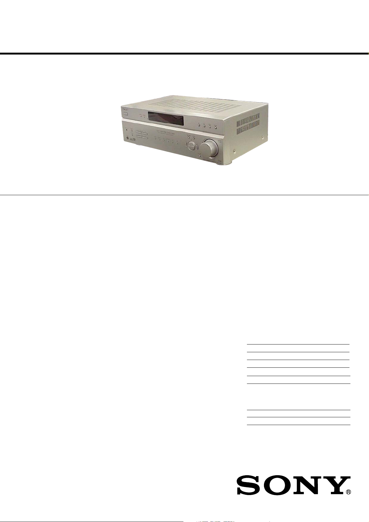
Photo : STR-K780
SPECIFICATIONS
2)
: 50 W/ch
2)
: 50 W
2)
: 50 W/ch
2)
: 85 W/ch
2)
: 85 W
2)
: 85 W/ch
2)
: 122W/ch
2)
: 12 2 W
2)
: 122W/ch
1)
2)
: 70 W/ch
2)
: 70 W
2)
: 70 W/ch
2)
: 70 W
2)
: 100 W/ch
2)
: 100 W
2)
: 100 W/ch
2)
: 10 0 W
AEP Model
UK Model
STR-K780
E Model
STR-K680/K780
Australian Model
STR-K780
Models of area code AR
Power Output
(6 ohms 1 kHz, THD 0.7%)
FRONT
CENTER2): W1), 65 W
SUR2): W/ch1), 65 W/ch
(6 ohms 100 Hz, THD 0.7%)
SUB WOOFER
(6 ohms 1 kHz, THD 10%)
FRONT
CENTER2): W
SUR2):W/ch1), 90 W/ch
(6 ohms 100 Hz, THD 10%)
SUB WOOFER
1)
Measured under the following conditions:
Area code Power requirements
SP, SP6, AEP, UK, RU 230 V AC, 50 Hz
AR 230 V AC, 50 Hz
E51, AUS 240 V AC, 50 Hz
MX 127 V AC, 60 Hz
2)
Depending on the sound field settings and the
source, there may be no sound output.
3)
Measured under the following conditions:
Area code Power requirements
AR 220 V AC, 50 Hz
1)3)
2)
: W/ch1), 65 W/ch
2)
2)
: 100
2)
70
70
70
: W1), 65 W
70
W/ch1), 90 W/ch
100
100
:W
100
— Continued on next page —
1)
, 90 W
1)
, 90 W
3)
3)
3)
3)
3)
3)
3)
3)
9-887-140-04
2006H16-1
© 2006.08
MULTI CHANNEL AV RECEIVER
Sony Corporation
Home Audio Division
Published by Sony Techno Create Corporation
STR-K680/K780
CENTER FRONT
LR
LR
+ +
Ver. 1.2
Inputs (An alog)
SA-CD/CD,
VIDEO 1, 2, DVD
Sensitivity: 800 mV
Impedance: 50 kohms
Inputs (Digital)
DVD (Coaxial) Sensitivity: –
VIDEO 1
(Optical)
(VIDEO 1 is only K780)
, 2
Impedance: 75 ohms
Sensitivity: –
Impedance: –
Outputs (Analog)
SUB WOOFER Voltage: 2 V
(only K780)
Impedance: 1 kohm
Reproduction frequency range:
28 – 20,000 Hz
Tone
Gain levels ±6 dB, 1 dB step
FM tuner section
Tuning ran ge 87.5 - 108.0 MHz
Antenna FM wire antenna
Antenna terminals 75 ohms, unbalanced
Intermediate Frequency
10.7 MHz
AM tuner section
Tuning range
Models of area code AEP, UK, RU,
SP, SP6, AUS
With 9-kHz tuning scale:
531 - 1,602 kHz
Antenna Loop antenna
Intermediate Frequency
450 kHz
Models of area code E51
With 10-kHz tuning scale: 530 – 1,610 kHz
With 9-kHz tuning scale: 531 – 1,602 kHz
Models of are code AR, MX
With 10-kHz tuning scale: 530 – 1,610 kHz
4)
You can change the AM tuning scale to 9 kHz or
10 kHz. After tuning in any AM station, turn off
the receiver. While holding down TUNING +,
press ?/1. All preset stations will be erased when
you change the tuning scale. To reset the scale to
10 kHz (or 9 kHz), repeat the procedure.
Video section
(only K780)
4)
Inputs/Outputs
Video: 1 Vp-p, 75 ohms
COMPONENT VIDEO:
Y: 1 Vp-p, 75 ohms
P
B/CB
/B-Y: 0.7 Vp-p,
75 ohms
R/CR
/R-Y: 0.7 Vp-p,
P
75 ohms
80 MHz HD Pass Through
General
Power requirements
Area code Power requirements
AEP, UK, RU 230 V AC, 50/60 Hz
AUS 240 V AC, 50 Hz
SP, SP6 230 – 240 V AC, 50/60 Hz
E51120/220/240 V AC,
50/60 Hz
4)
MARX1
27 V AC, 60 Hz
220-230V AC, 50/60 Hz
Power consumption
Area code Power consumpti on
AEP, UK, AUS, 190 W
E51, MX, RU, AR
SP, SP6
170 W
Power consumption (during standby mod e)
0.2 W
Dimensions (w/h/d) (Approx.)
430 × 145 × 300 mm
including proj ecting parts
and controls
Mass (Approx.) 7.5 kg
7.8 kg
(K780)
(K680)
Design and specifications are subject to
change without notice.
•Abbreviation
AR : Argentina model
AUS: Australian model
E51 : Chilean and Peruvian models
MX : Mexican model
RU : Russian model
SP : Singapore model
SP6 : Singapore and Malaysia models
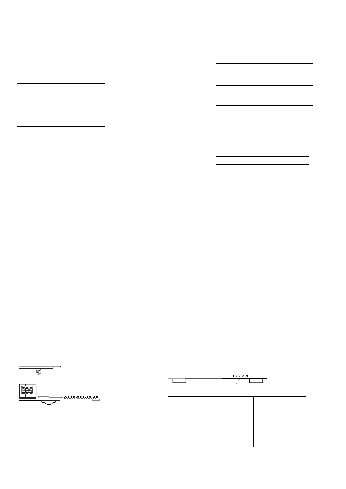
About area codes
The area code of the receiver you purchased is
shown on the lower right portion of the rear panel
(see the illustration below).
Area code
Any differences in operation, according to the area
code, are clearly indicated in the text, for example,
“Models of area code AA only”.
MODEL IDENTIFICATION
– Rear Panel –
Parts No.
Model Part No.
E51 model 2-661-458-2[]
AR model 2-661-458-3[]
MX model 2-661-458-4[]
AEP, UK, RU models 2-662-452-0[]
SP, SP6 models 2-662-452-1[]
AUS model 2-662-452-2[]
2

STR-K680/K780
Notes on chip component replacement
• Never reuse a disconnected chip component.
• Notice that the minus side of a tantalum capacitor may be
damaged by heat.
UNLEADED SOLDER
Boards requiring use of unleaded solder are printed with the leadfree mark (LF) indicating the solder contains no lead.
(Caution: Some printed circuit boards may not come printed with
the lead free mark due to their particular size)
: LEAD FREE MARK
Unleaded solder has the following characteristics.
• Unleaded solder melts at a temperature about 40 °C higher
than ordinary solder.
Ordinary soldering irons can be used but the iron tip has to be
applied to the solder joint for a slightly longer time.
Soldering irons using a temperature regulator should be set to
about 350 °C.
Caution: The printed pattern (copper foil) may peel away if
the heated tip is applied for too long, so be careful!
• Strong viscosity
Unleaded solder is more viscou-s (sticky, less prone to flow)
than ordinary solder so use caution not to let solder bridges
occur such as on IC pins, etc.
• Usable with ordinary solder
It is best to use only unleaded solder but unleaded solder may
also be added to ordinary solder.
SAFETY-RELATED COMPONENT WARNING!!
COMPONENTS IDENTIFIED BY MARK 0 OR DOTTED LINE
WITH MARK 0 ON THE SCHEMATIC DIAGRAMS AND IN
THE PARTS LIST ARE CRITICAL TO SAFE OPERATION.
REPLACE THESE COMPONENTS WITH SONY PARTS WHOSE
PART NUMBERS APPEAR AS SHOWN IN THIS MANUAL OR
IN SUPPLEMENTS PUBLISHED BY SONY.
TABLE OF CONTENTS
1. GENERAL ................................................................... 4
2. TEST MODE ............................................................... 11
3. DIAGRAMS
3-1. Block Diagram – MAIN Section –.................................. 14
3-2. Block Diagram – DISPLAY/POWER Section – ............. 15
3-3. Printed Wiring Board – DIGITAL Board (Side A) –...... 16
3-4. Printed Wiring Board – DIGITAL Board (Side B) –...... 17
3-5. Schematic Diagram – DIGITAL Board (1/3) – .............. 18
3-6. Schematic Diagram – DIGITAL Board (2/3) – .............. 19
3-7. Schematic Diagram – DIGITAL Board (3/3) – .............. 20
3-8. Printed Wiring Board – MAIN Board – ......................... 21
3-9. Schematic Diagram – MAIN Board (1/3) – ................... 22
3-10. Schematic Diagram – MAIN Board (2/3),
HEADPHONE Board –................................................... 23
3-11. Schematic Diagram – MAIN Board (3/3),
AC SELECT Board, ADCC Board,
STANDBY Board – ......................................................... 24
3-12. Printed Wiring Boards
– ADCC Board, HEADPHONE Board – ........................ 25
3-13. Printed Wiring Boards
– STANDBY Board, AC SELECT Board – .................... 26
3-14. Printed Wiring Board – DISPLAY Board – ................... 27
3-15. Printed Wiring Boards
– TUNING Board, POWER Board – .............................. 28
3-16. Schematic Diagram – DISPLAY Board,
TUNING Board, POWER Board – ................................. 29
3-17. Printed Wiring Board – VIDEO Board –........................ 30
3-18. Schematic Diagram – VIDEO Board – .......................... 31
4. EXPLODED VIEWS
4-1. Front Panel Section ......................................................... 39
4-2. Chassis Section................................................................ 40
5. ELECTRICAL PARTS LIST .................................. 41
3
STR-K680/K780
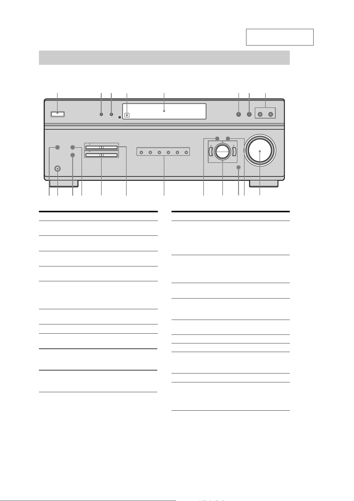
Receiver
Front panel
SECTION 1
GENERAL
This section is extracted
from instruction manual.
1 2 34 6 7 8
?/1
AUTO CAL MIC
PHONES
MEMORY
FM MODE TUNING
DISPLAY DIMMER
PRESET TUNING
+
+
VIDEO 1 VIDEO 2 DVD SA-CD/CD FM AM
5
AMP MENU ENTER MASTER
INPUT MODE
qjqkqlw; qgqh qf qaq;qsqd
Name Function
A ?/1 Press to turn the re ceiver
on or off.
B DISPLAY Press to select informat ion
displayed on the display.
C DIMME R Press to adjust the
brightness of the display.
D Remote sensor Receives signals from
remote commander.
E Display The current status of the
selected component or a
list of selectable items
appears her e.
F 2CH Press to select 2CH
STEREO mode.
G A.F.D. Press to select A.F .D. mode.
H MOVIE,
MUSIC
I MASTER
VOLUME
J ENTER Press to store a station or
Press to select sound fields
(MOVIE, MUSIC).
Tur n to adj ust the volume
level of all speakers at the
same time.
enter the selection when
selecting the settin g s .
Name Function
K INPUT MODE Press to select the input
mode when the same
components are connected
to both digital and analog
jacks.
L I/i/U/u After pressing AMP
MENU (M), press I or i
and U or u to se lect the
settings.
M AMP MENU Press to display the menu
of the receiver.
N Input buttons Press one of the buttons to
select the component you
want to use.
O PRESET
TUNING +/–
P TUNING +/– Press to scan a station.
Q MEMORY Press to store a station.
R FM MODE Press to select FM
S PHONES jack Connects to a headpho ne.
T AUTO CAL MIC
jack
Press to select a pre s et
station.
monaural or stereo
reception.
Connects to the supplied
ECM-AC2 optimizer
microphone for the Auto
Calibration function.
2CH A.F.D. MOVIE MUSIC
VOLUME
9
4
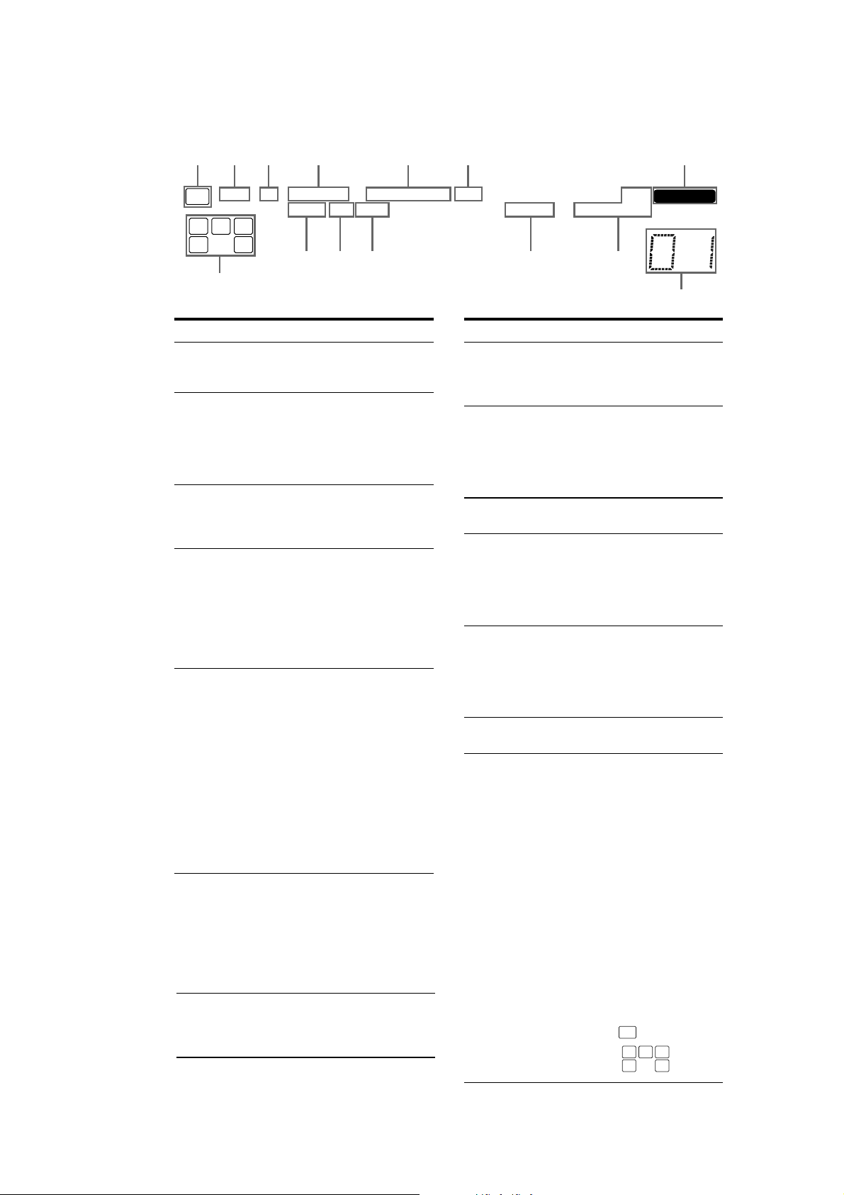
About the indicators on the display
214356 7
STR-K680/K780
SW
LFE
SP
DIGITAL
;
;
PRO LOGIC II
SLEEP OPT COAX
L C R
SLSSR
qaqs
qf
Name Function
A SW Li ghts up when audio sign al is
B LFE Lights up when the disc being
C SP Lights up when the receiver is
D ;DIGITAL Lights up when Dolby Digital
E ; PRO
LOGIC (II)
F DTS Lights up when DTS signals are
G MEMORY Lights up when a memory
output fr om the SUB WOOFER
jack.
played back contains an LFE
(Low Frequency Effect)
channel and the LFE channel
signal is actually being
reproduced.
turned on. This indicator does
not light up if a headphone is
connected to the PHONES jack.
signals are input.
Note
When playing a Dolby Digital
format disc, be sure that yo u
have made digital connections
and that INPUT MODE is not
set to “ANALOG”.
“; PRO LOGIC” lights up
when the receiver applies Pro
Logic proces s i ng to 2 channel
signals in order to output the
center and surround channel
signals. “; PRO LOGIC II”
lights up when the Pro Logic II
Movie/Music decoder is
activated.
Note
Dolby Pro Logic an d Dolby Pro
Logic II decoding do not
function for DTS format
signals.
input.
Note
When playing a D TS format
disc, be sure that you have made
digital connections and that
INPUT MODE is not s et to
“ANALOG”.
function, such as Name Input,
Preset Memory, et c., is
activated.
DTS
RDS
MEMORY
STEREO MONOD.RANGE
q; 9qd
8
Name Function
H Preset
station
indicators
I Tuner
indicators
J D.RANGE Lights up when dynamic range
K COAX Lights up when INPUT MODE
L OPT Lights up when INPUT MODE
M SLEEP Lights up when the Sleep Timer
N Playback
channel
indicators
L
R
C
SL
SR
S
Lights up when using the
receiver to tune in radio stations
you have preset. For details on
presetting radio stations.
Lights up when using the
receiver to tune in radio stations,
etc.
Note
“RDS” appears for mo de ls of
area code AEP, UK onl y.
compression is activated.
is set to “ A UT O” and the source
signal is a di gital signal being
input through the COAXIAL
jack, or when INPUT MODE is
set to “COAX IN”.
is set to “ A UT O” and the source
signal is a di gital signal being
input through the OPTICAL
jack, or when INPUT MODE is
set to “OPT IN”.
function is activated.
The letters (L, C, R, etc.)
indicate the channels being
played back. The boxes around
the letters vary to show how the
receiver downmixes the source
sound.
Front Left
Front Right
Center (monaural)
Surround Left
Surround Right
Surround (monaural or the
surround component s obtained
by Pro Logic processing)
Example:
Recording format (Front/
Surround): Dolby Digital 3/2.1
Sound Field: A.F.D. AUTO
SW LFE
L C R
SL SR
5
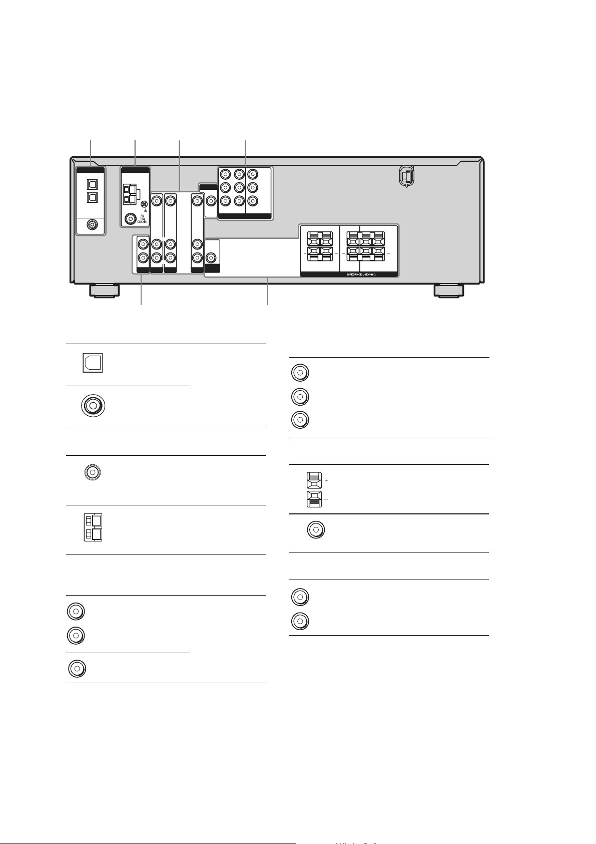
STR-K680/K780
Rear
panel
STR-K780 model
VIDEO IN VIDEO IN
L
R
AUDIO IN
AUDIO IN
DVD
VIDEO 2
3
L
R
2
DIGITAL
OPTICAL
VIDEO 1
IN
VIDEO 2
IN
DVD IN
COAXIAL
ANTENNA
L
R
SA-CD/CD
AM
AUDIO IN
A DIGITAL INPUT section
OPTICAL
IN jack
COAXIAL IN
jack
41
MONITOR
VIDEO IN
VIDEO OUT
DVDINVIDEO 2INMONITOR
OUT
COMPONENT VIDEO
AUDIO
OUT
AUDIO IN
SUB
WOOFER
VIDEO 1
Connects to a DVD
player, etc. The
COAXIAL ja ck
provides a better
quality of loud
sound.
Y
B/CB
P
/B–Y
R/CR
P
/R–Y
LR
+ +
LR
SURROUND
SPEAKERS
+ +
CENTER FRONT
LR
LR
56
D COMPONENT VIDEO INPUT/
OUTPUT section
Green
Blue
Red
COMPONENT
VIDEO
INPUT/
OUTPUT
jack*
Connects to a DVD
player, TV, or a
satellite tuner . You
can enjoy high
quality image.
B ANTENNA section
FM
ANTENNA
AM
ANTENNA
Connects to the
FM wire antenna
supplied with this
receiver.
Connects to the
AM loop antenna
supplied with this
receiver.
C VIDEO/AUDIO INPUT/OUTPUT
section
White (L)
Red (R)
Yellow
AUDIO IN/
OUT jack
VIDEO IN/
OUT jack*
Connects the video
and audio jacks of
a VCR or a DVD
player.
E SPEAKER section
Connects to the
speakers.
Connects to the
sub woofer.
F AUDIO INPUT section
White (L)
AUDIO IN
jack
Red (R)
*You can watch the selected input image when y ou
connect the MON ITOR OUT ja ck to a TV monito r.
Connects to a CD
player, etc.
6
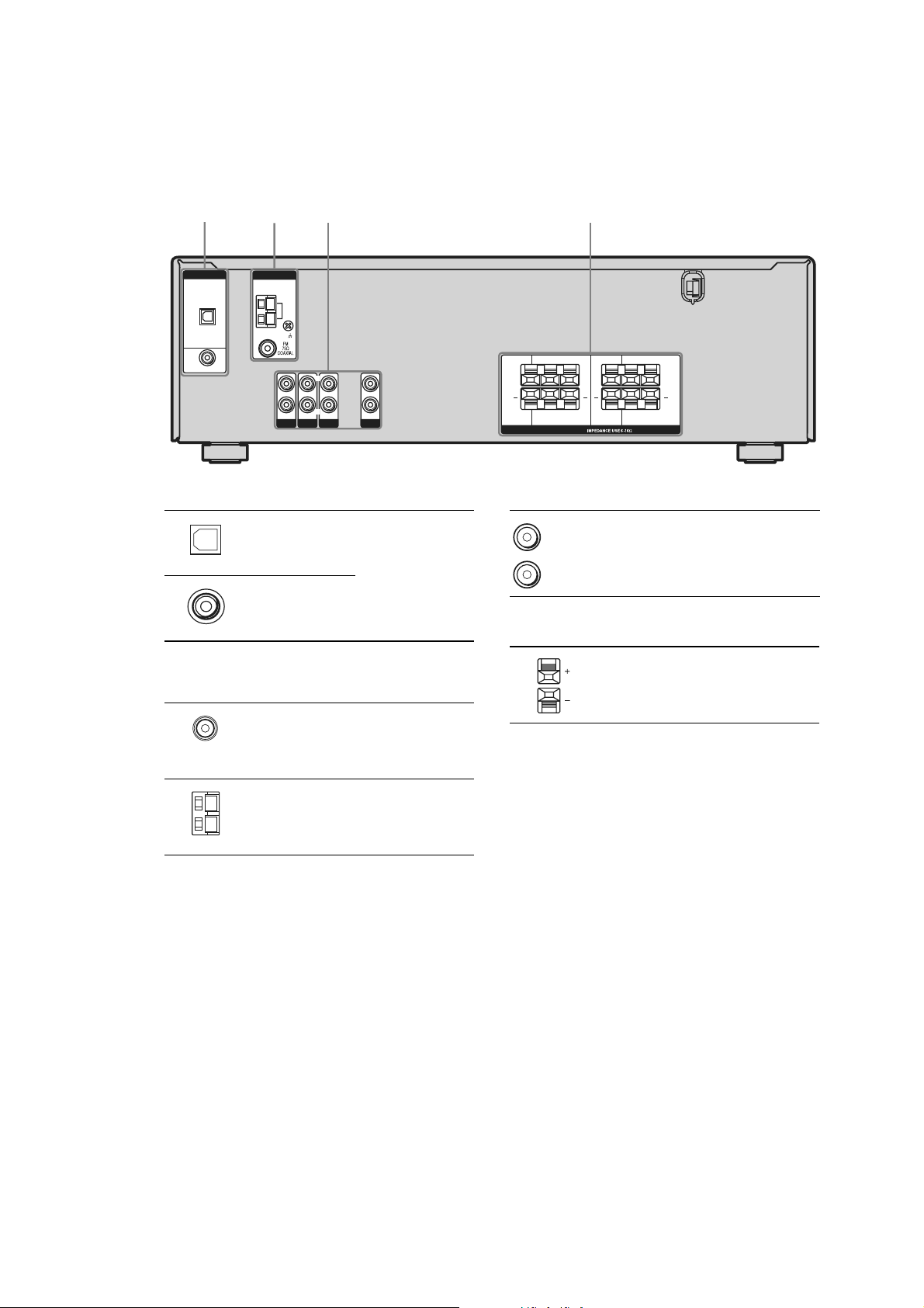
STR-K680/K780
Rear pan
el
STR-K680 model
1
DIGITAL
OPTICAL
VIDEO 2
IN
DVD IN
COAXIAL
ANTENNA
L
R
A DIGITAL INPUT section
OPTICAL
IN jack
COAXIAL IN
jack
AM
AUDIO IN
SA-CD/CD
AUDIO IN
DVD
3 42
L
R
AUDIO IN
VIDEO 2
L
R
AUDIO IN
VIDEO 1
Connects to a DVD
player, etc. The
COAXIAL jack
provides a better
quality of loud
sound.
+ +
SUB
SURROUND
WOOFER
SPEAKERS
LR
+ +
LR
CENTER FRONT
LR
LR
C AUDIO INPUT section
White (L)
Red (R)
AUDIO IN
jack
D SPEAKER section
Connects to a CD
player, etc.
B ANTENNA section
FM
ANTENNA
AM
ANTENNA
Connects to the
speakers and sub
woofer.
Connects to the
FM wire antenna
supplied with this
receiver.
Connects to the
AM loop antenna
supplied with this
receiver.
7
STR-K680/K780
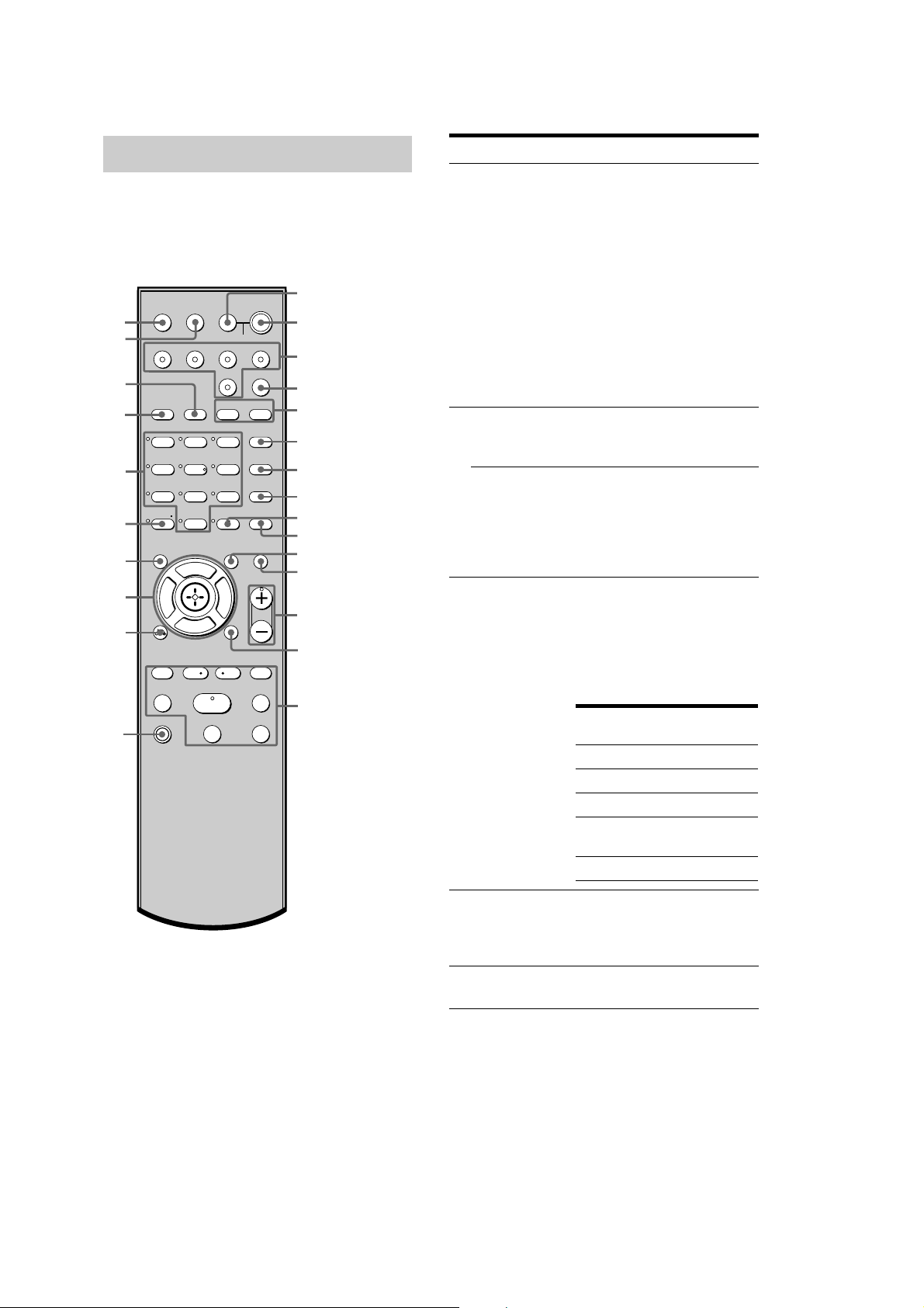
Remote commander
You can use the supplied remote RM-AAU006
to operate the receiver and to control the Sony
audio/video components that the remote is
assigned to operate.
AV ?/1
1
TV
TV/VIDEO
AUTO
SLEEP
wg
wf
VIDEO 1 VIDEO 2 DVD SA-CD/CD
wd
ws
wa
w;
2CH A.F.D.
123
46
78
>10/
-
CLEAR
ql
qk
qj
Gg
RETURN/EXIT
TV CH –
REPLAY ADVANCE
PRESET –
.
TUNING –
TV
qh
?/1
AV
?/1
?/1
CAL
SYSTEM STANDBY
TUNER
AMP MENU
MOVIE MUSIC
DUAL MONO
5
0/10
F
f
<
FM MODE
D.TUNING
9
D.SKIP
MEMORY DVD MENU
ENTER
MUTING
TOOLSDISPLAY
TV VOL
MASTER VOL
MENU
TV CH +
PRESET +
<
>
TUNING +
HmM
Xx
(on/standby) switch
TV ?/1, ?/1
2
(
on/standby) switch
3
4
5
6
7
8
9
q;
qa
qs
qd
qf
qg
Name Function
A AV ?/1 Press to turn on or off the
Sony audio/video components
that the remote is assigned to
operate.
If you press ?/1 (B) at the
same time, it will turn off the
receiver and other
components (SYST EM
STANDBY).
Note
The function of the AV ?/1
switch changes aut omatically
each time you press the input
buttons (C).
B TV ?/1 Press TV ?/1 and TV (P) at
the same time to turn the TV
on or off.
?/1 Press to turn the recei ver o n or
off.
To turn off all components,
press ?/1 and AV ?/1 (A) at
the same ti me (SYSTEM
STANDBY).
C Input buttons Press one of the buttons to
select the componen t you
want to use. When you press
any of the input buttons, th e
receiver turns on. The buttons
are factory assigned to control
Sony components as follows.
Button Assigned Sony
component
VIDEO 1 VCR (VTR mode 3)
VIDEO 2 VCR (VTR mode 2)
DVDDVD player
SA-CD/CD Super Audio CD/CD
player
TUNER Built-in tuner
D AMP ME NU Press to display the menu of
the receiver. Then, use the
control buttons to perform
menu operations.
E MOVIE,
MUSIC
Press to select sound fields
(MOVIE, MUSIC).
8

STR-K680/K780
Name Function
F DUAL MONO Press to select the language
you want during digital
broadcast.
G FM MODE Press to select FM monaural
or stereo reception.
H D.TUNING Press to enter direct tuning
mode.
D.SKIP Press to skip disc of the CD
player or DVD player (multidisc changer only).
I ENTER Press to enter the value after
selecting a channel, disc or
track using the numeric
buttons.
MEMORY Press to store a station.
J DVD ME NU Press to display the men u of
the DVD player on the TV
screen. Then, use the control
buttons to perform menu
operations.
K TOOLS Press to display options
applicable to the entire dis c
(e.g. disc protection), recorder
(e.g. audio settings durin g
recording), or multiple items
on a list menu (e.g. erasin g
multiple titles).
L MUTING Press to mute th e sound.
M TV VOL
+*/–
MASTER VOL
+*/–
N MENU Press to display the menus of
Press TV VOL +/– and TV
(P) at the same time to adjust
the TV volume level.
Press to adjust the volume
level of all speakers at the
same time.
the VCR, DVD player, or
satellite tuner on the TV
screen. Then, use the control
buttons to perform menu
operations.
Name Function
O ./> Press to skips tracks of the CD
player, DVD player, or tape
deck.
REPLAY /
ADVANCE
m/M Press to
H* Press to start playback of the
X Press to pause playback or
x Press to stop playback of the
TV CH +/– Press TV CH +/– and TV (P)
PRESET +/– Press to select
TUNING +/– Press to scan a station.
P TV Press TV and the button you
Q RETURN/
EXIT O
<
Press to replay the previous
<
scene or fast forward the
current scene of the VCR or
DVD player.
–search tracks in the forward/
backward direction of the
DVD player.
–fastforwa rd/ rewind of the
VCR, CD player, or tape
deck.
VCR, CD player, D VD player,
or tape deck.
recording of the VCR, CD
player, DVD player, or tape
deck. (Also starts recording
with components in recording
standby.)
VCR, CD player, D VD player,
or tape deck.
at the same time to select
preset TV channels.
–preset stations.
–preset cha nne ls of the VCR
or satellite tuner.
want at the same time to
activate the button s wi th
orange printing.
Press to
–return to the previous menu.
–exit the menu while the
menu or on-screen guide of
the VCR, DVD player, or
satellite tuner is displayed
on the TV screen.
9

STR-K680/K780
Name Function Name Function
R Control
buttons
S DISPLAY Press to select the information
T -/-- Press -/-- an d TV (P) at the
x
>10/
CLEAR Press to
U Numeric
buttons
(number 5*)
V 2CH Press to select 2CH STEREO
W A.F.D. Press to select A.F.D. mode.
X AUTO CAL Press to activate the Auto
After pressing AMP MENU
(D), DVD MENU (J), or
MENU (N), press the control
button V, v, B or b to select
the settings. When you press
DVD MENU or MENU, press
the control button to enter the
selection.
displayed on the TV screen of
the VCR, satellite tuner, CD
player or DVD player.
same ti me to select the
channel entry mode, eith er
one or two digits of the TV.
Press to select
–track numbers over 10 of the
VCR, satellite tuner or CD
player.
–channel numbers of the
Digital CATV terminal.
–clear a mistake when you
press the incorrect num er ic
buttons.
– return to continuous
playback, etc. of the satellite
tuner or DVD player.
Press to
–preset/tune to preset
stations.
–select track numbers of the
CD player or DVD player.
Press 0/10 to select track
number 10.
–select channel numbers of
the VCR or satellite tuner.
Press the numeric buttons and
TV (P) at the same time to
select the TV channels.
mode.
Calibration function.
Y TV/VIDEO Press TV/VIDEO and TV
(P) at the same time t o select
the input signal (TV input or
video input).
SLEEP Press to activate the Sleep
Timer function and the
duration which the receiver
turns off automatically.
*The number 5, MASTER VOL +, TV VOL +, and
H buttons have tactile dots. Use the ta ctile dots as
references whe n operating the rece iver.
Notes
Some functions explained in this section may not
work depending on the model.
The above explanati on is intended to s erve as an
example only. Therefore, depending on the
component, the above operation may not be
possible or may operate differently than described.
10
SECTION 2
TEST MODE
STR-K680/K780
FACTORY PRESET MODE
All preset contents are reset to the default setting.
Procedure:
1. While depressing the PRESET TUNING – and the
DIMMER buttons simultaneously, press the power ?/1
button to turn on the main power.
2. The message “FACTORY” appears and the present contents
are reset to the default values.
AM CHANNEL STEP 9 kHz/10 kHz
SELECTION MODE
Either the 9 kHz step or 10 kHz step can be selected for the AM
channel step.
Procedure:
1. Set the FUNCTION to AM. Turn off the main power.
2. While depressing the TUNING + button, press the power
?/1 button to turn on the main power.
3. Either the message “9 k STEP” or “10 kSTEP” appears. Select
the desired step.
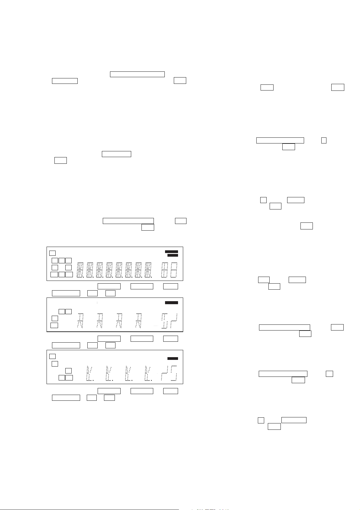
FLUORESCENT INDICATOR TUBE TEST MODE
All fluorescent segments are tested. When this test is acti v ated, all
segments turn on at the same time, then each segment turns on one
after another.
Procedure:
1. While depressing the PRESET TUNING – and the AM
buttons simultaneously, press the power ?/1 button to turn
on the main power.
2. All segments turn on.
dB
kHz
mft.
MHz
dB
kHz
mft.
MHz
kHz
mft.
MHz
MEMORY
DIRECT
MEMORY
DIRECT
MEMORY
DIRECT
SP A
D
D
LFE
SW
CR
L
SL S SR
SBL SB SBR
D
SP B SLEEP OPT COAX MULTI CH IN 96/24
D
DIGITALEX PRO LOGIC II x DTS-ES NEO:6 MPEG-2 AAC RDS
D.RANGE EQ STEREO MONO
3. Press either of the VIDEO1 or VIDEO2 or DVD or
SA-CD/CD or FM or AM button.
SP A
D
D
LFE
LSWR
S
SB
D
SP B SLEEP OPT COAX MULTI CH IN 96/24
D
DIGITALEX PRO LOGIC II x DTS-ES NEO:6 MPEG-2 AAC RDS
D.RANGE EQ STEREO MONO
4. Press either of the VIDEO1 or VIDEO2 or DVD or
SA-CD/CD or FM or AM button once again.
SP A
D
D
D
DIGITALEX PRO LOGIC II x DTS-ES NEO:6 MPEG-2 AAC RDS
D.RANGE EQ STEREO MONO
C
SL SR
SBL SBR
D
SP B SLEEP OPT COAX MULTI CH IN 96/24
5. Press either of the VIDEO1 or VIDEO2 or DVD or
SA-CD/CD or FM or AM b utton once again. All segments
turn off.
SOUND FIELD CLEAR MODE
The preset sound field is cleared when this mode is activa ted. Use
this mode before returning the product to clients upon completion
of repair.
Procedure:
1. While depressing the 2CH button, press the power ?/1
button to turn on the main power.
2. The message “SF. CLR.” appears and initialization is
performed.
SOFTWARE VERSION DISPLAY MODE
The software version is displayed.
Procedure:
1. While depressing the PRESET TUNING – and the < buttons
simultaneously, press the power ?/1 button to turn on the
main power.
2. The model name, destination and the software version are
displayed.
KEY CHECK MODE
Button check
Procedure:
1. While depressing the < and the A.F.D. buttons simultaneously, press the power ?/1 button to turn on the main
power.
“REST 25” appears.
2. Every pressing of any button other than ?/1 counts down
the buttons. The buttons which are already counted once are
not counted again.
3. When all buttons are pressed “REST 00” appears.
SHIPMENT MODE
All preset contents are reset to the default setting.
Procedure:
1. While depressing the AM and the A.F.D. buttons simultaneously, press the power ?/1 button to turn on the main
power.
2. “CLEARED” appears and switch off the set.
PROTECTOR
Procedure:
1. While depressing the PRESET TUNING – and the 2CH
buttons simultaneously, press the power ?/1 button to turn
on the main power.
2. “PROT. EVER” appears and switch off the set.
DECODE AUTO ALL
Procedure:
1. While depressing the PRESET TUNING – and the + buttons simultaneously, press the power ?/1 button to turn on
the main power.
2. “DEC. TEST” appears and switch off the set.
VACS CONTROL
Procedure:
1. While depressing the < and the DIMMER buttons simultaneously, press the power ?/1 button to turn on the main
power.
2. “VACS OFF” appears. (8 second)
11
STR-K680/K780
Ver. 1.3
SWAP ALL MODE
Procedure:
1. While depressing the PRESET TUNING – and the A.F.D.
buttons simultaneously, press the power ?/1 button to turn
on the main power.
2. “SWP.ALL” appears. (No change while displayed.)
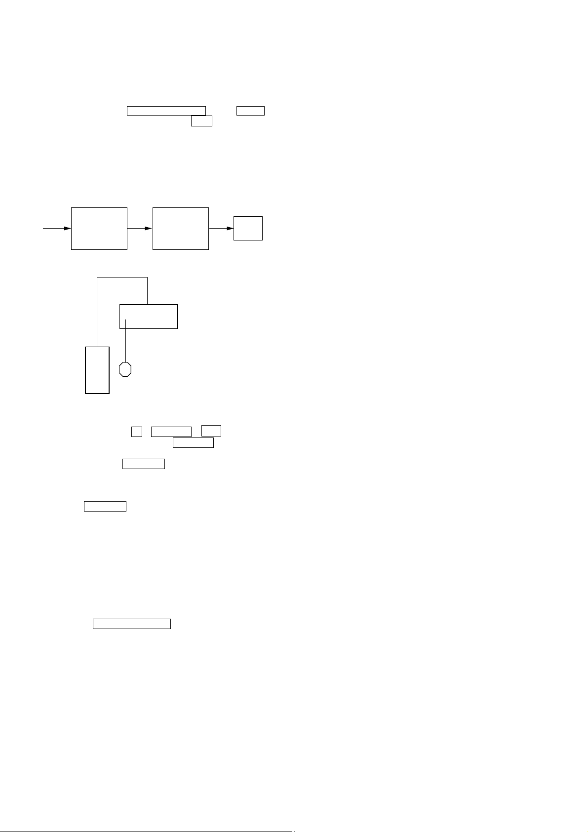
ADCC FACTORY TEST MODE
ADCC Factory Test mode have two stages:
1. ADCC DSP Data Line Checking
2. ADCC AUTO CAL MIC board Checking
Start Pass Pass
DSP Data Line
Check
Factory Test System Setup
Auto Cal Mic
Check
END
Receiver
ADCC MIC
SPK Front Left
1. When power off :
Press the three buttons < + DISPLAY + ?/1 .
(If it doesn’t operate, please press DISPLAY again afetr 2
seconds.)
Afterward, press the DIMMER to start DCAC factory test
mode.
1. ADCC DSP Data Line Checking
After press the DIMMER , DCAC Factory test mode will start,
below display will show:
“DCAC[][][]x” x = 1, 2, 3
If there is error happen, below display will show:
“ERR[]SD0x” x = 1 → D1112 or R1198 problem
x = 2 → D1113 problem
x = 3 → D1114 problem
2. ADCC AUTO CAL MIC board Checking
Connect front left speaker of the receiver and AUTO CAL
microphone. Turn MASTER VOLUME jog, there will be test tone
sound output from front left speaker, and the display will change
accordingly.
“AD []-[]xxx” xxx = 0 to 255 (depends on loudness of test tone)
12
SECTION 3
DIAGRAMS
STR-K680/K780
Ver. 1.2
THIS NOTE IS COMMON FOR PRINTED WIRING BOARDS AND SCHEMATIC DIAGRAMS.
(In addition to this, the necessary note is printed in each block.)
For Schematic Diagrams.
Note:
• All capacitors are in µF unless otherwise noted. (p: pF)
50 WV or less are not indicated except f or electrolytics and
tantalums.
• All resistors are in Ω and 1/
specified.
• % : indicates tolerance.
• f : internal component.
• 2 : nonflammable resistor.
• 5 : fusible resistor.
• C : panel designation.
Note: The components identified by mark 0 or dotted
line with mark 0 are critical for safety.
Replace only with part number specified.
• A : B+ Line.
• B : B– Line.
•Voltages and waveforms are dc with respect to ground under no-signal (detuned) conditions.
No mark : FM
•Voltages are taken with a VOM (Input impedance 10 MΩ).
Voltage v ariations ma y be noted due to normal production
tolerances.
•Waveforms are taken with a oscilloscope.
• Circled numbers refer to waveforms.
• Signal path.
F : FM
J : ANALOG
c : DIGITAL
I : VIDEO
•Abbreviation
AR : Argentina model
AUS:Australian model
E51 : Chilean and Peruvian models
MX : Mexican Model
RU : Russian model
SP : Singapore model
SP6 : Singapore and Malaysia models
4
W or less unless otherwise
For Printed Wiring Boards.
Note:
• X : parts extracted from the component side.
• a: Through hole.
• f : internal component.
• : Pattern from the side which enables seeing.
Caution:
Pattern face side: Parts on the pattern face side seen from
(Side B) the pattern face are indicated.
Parts face side: Parts on the parts face side seen from
(Side A) the parts face are indicated.
• Indication of transistor.
C
Q
B
E
B
These are omitted.
CE
These are omitted.
• Circuit Boards Location
ADCC board
TUNING board
HEADPHONE board
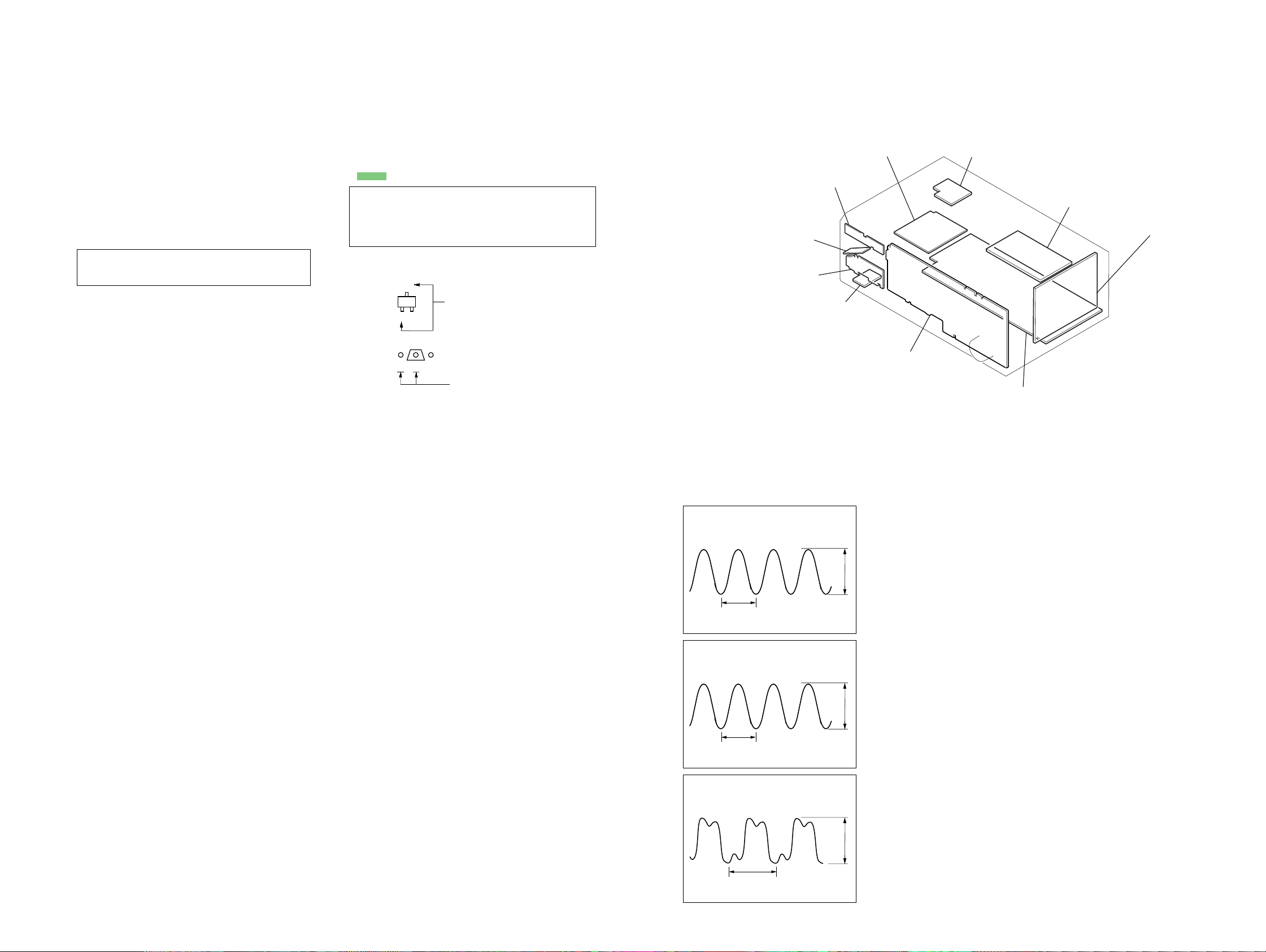
•Waveforms
– DIGITAL Board –
1
IC1501 9 (MCLK1)
POWER board
STANDBY board
DISPLAY board
AC SELECT board (E51 only)
VIDEO board (K780 only)
DIGITAL board
MAIN board
STR-K680/K780
72 ns
1 V/DIV, 40 ns/DIV
2
IC1101 id (X1)
41.6 ns
1 V/DIV, 20 ns/DIV
3
IC1301 ws (XIN)
81 ns
1 V/DIV, 40 ns/DIV
1313
3.4 Vp-p
4.2 Vp-p
4.4 Vp-p
STR-K680/K780
Ver. 1.1
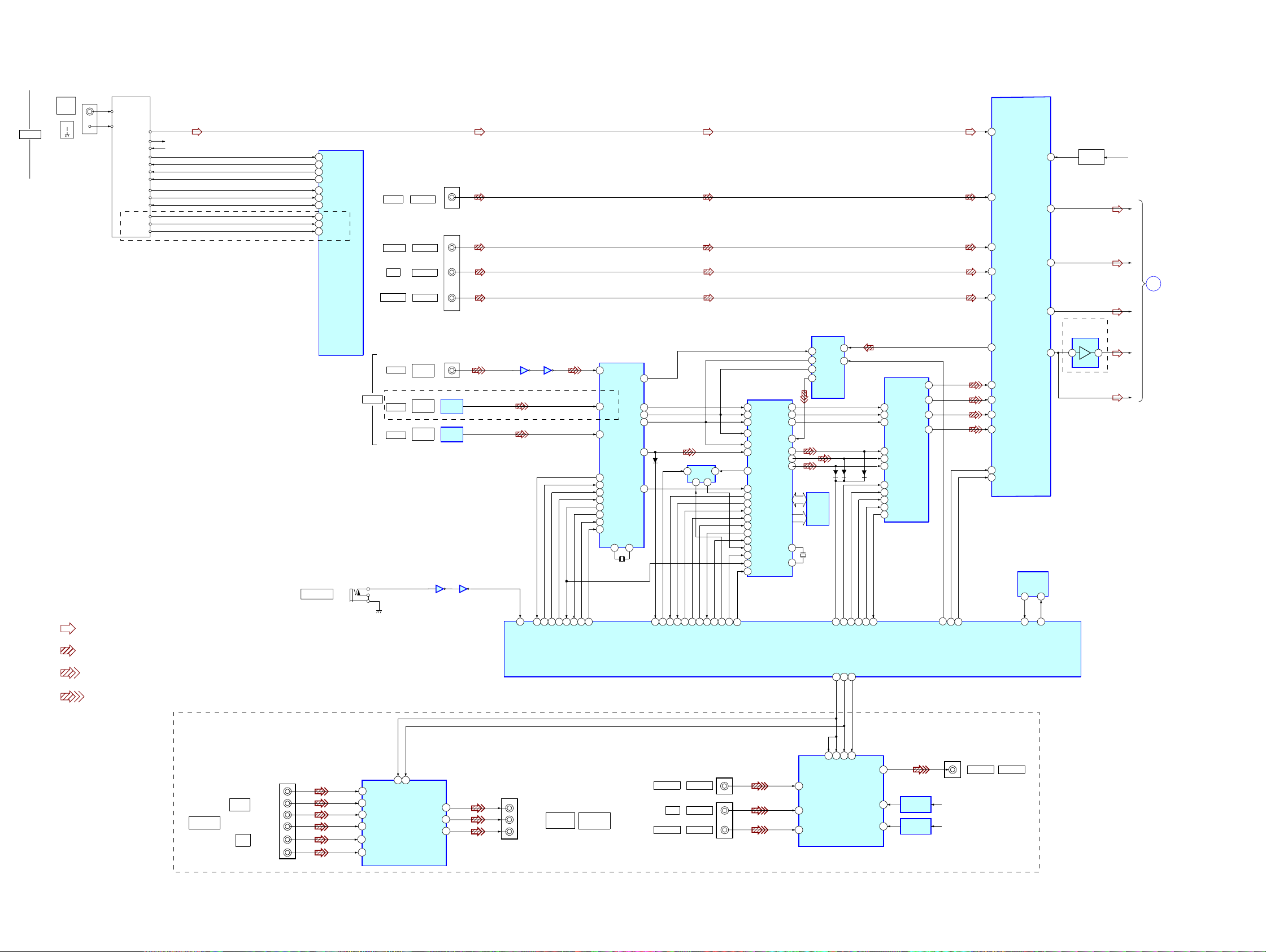
3-1. BLOCK DIAGRAM – MAIN SECTION –
ANTENNA
TN1
FM
75 Ω
COAXIAL
AM
TUNER PACK
FM
AM
FM SIG OUT
R CH
ST-DO
ST-DI
STEREO
TUNED
MUTING
RDS_INT
RDS_DATA
L CH
CLK
CE
AEP,UK,RU
• R-CH is omitted due to same as L-CH.
• Signal Path
: FM
: ANALOG
: DIGITAL
R-CH
TUNER +10V10V
73
17
16
74
76
75
78
43
52
53
AUTO CAL MIC
IC1101(1/3)
SYSTEM CONTROLLER
DO
TUNER-DATA
T.SERIAL CLK
SLATCH
STEREO
TUNED
MUTE
RDS_SIG
RDS_CLK
RDS_DATA
J2000
DIGITAL
VIDEO 1
VIDEO 2
DVD
SA-CD/CD
COAXIAL
OPTICAL
OPTICAL
K780
AUDIO IN
AUDIO IN
AUDIO IN
AUDIO IN
DVD
IN
VIDEO 1
IN
VIDEO 2
IN
IC2000(1/2)
57
J402
J400
J1301
IC1352
OPTICAL
IN
IC1353
OPTICAL
IN
IC2000(2/2)
3
IC400
ANALOG SOUND
PROCESSOR
10
INL1
DVDD
26
2
INL5
LOUT
49
4
INL4
SLOUT
COUT
SWOUT
IC1131
EEPROM
SDA SCL
5 6
29 30
SDA
40
33
32
SCL
6
INL3
8
INL2
IC1401
AD CONVERTER
13
LIN
IC1301
DIGITAL AUDIO
93
XSTATE
XMODE
CKSEL1
5
3
4
35
36
38
37
34
17
48
47
I/F RECEIVER
DIN2
DIN0
DIN1
DO
DI
CLK
CE
ERROR
XSTATE
XMODE
CKSEL1
XIN XOUT
22 21
X1301
12.288MHz
XMCK
CK OUT
LRCK
DATAO
AUDIO
20
IC1501
AUDIO DSP
22
SCK OUT
13
BCK
14
15
16
24
DATA0
D1301
92
LRCK_SW
2
18
GP9
19
HD OUT
6
20
HD IN
IC1503
SELECTOR
SB
AY
1 5
4
5
HCS
HCLK
HACN
2
7PM3
KFSI0
29
BCKI2
28
LRCKI2
17
BCKII
15
LRCKII
30
SDI2
19
LRCK0
69
GP8
68
GP9
35
HD OUT
33
HD IN
34
HCLK
36
HCS
32
HACN
PM
113
56
BST
2
XRST
59
EXLOCK
37
GP12
6
8
BST
XRST
GP12
14
BCKO
20
19LRCKO
18SDI1
SDO1
23
SDO2
24
SDO3
25
MCLK1
9
MCLK2
12
IC1101(2/3)
SYSTEM CONTROLLER
IC1303(2/2)
IC1303(1/2)
35
62
1
45
98 97 95 96 99 100 94 1
DI
CE
DO
CLK
ERROR
ADCC_ANA_OGUE_IN
16
13
14
15
IC1502
SRAM
X1502
13.9MHz
SYSCLK
LRCK
BCK
DOUT
D1113
1
RST
6
10
57
ADCC_DSP_IN
D1112
12
13
14
PCM1608_MC
PCM1608_ML
PCM1608_RST
38
40
41
47
45
46
D1114
37
36
35
34
33
15
PCM1608_MDI
PCM1608_MDO
IC1452
AUDIO CODEC
SCK1
BCK
LRCK
DATA3
DATA1
DATA2
RST
ML
MC
MDI
MDO
VOUT5
VOUT1
VOUT3
VOUT4
10
14
12
11
9
21
22
PCM1800_RST
VOL_DATA_LATCH
VOL_CLK
ADIFL
16
LIN
19
SLIN
20
CIN
21
SWIN
24
DATA
25
CLK
Q471
+3.3V REG
IC502
WOOFER AMP
37
K680
+7V
L
SL
SL
DISPLAY/
POWER
A
SECTION
(Page 15)
C
SBL
SW
888786
: VIDEO
STR-K680/K780
K780
COMPONENT
VIDEO
VIDEO 2
IN
DVD
11
4S22S213
M
J201
J251
(1/2)
Y
PB/CB/B-Y
PR/CR/R-Y
Y
PB/CB/B-Y
IN
PR/CR/R-Y
3
CH1 IN2
9
CH2 IN2
14
CH3 IN2
5
CH1 IN3
11
CH2 IN3
12
CH3 IN3
4
SW1 2SW2
IC251
VIDEO AMP
CH1 OUT
CH2 OUT
CH3 OUT
J251
(2/2)
22
20
18
Y
PB/CB
/B-Y
PR/CR
/R-Y
MONITOR
OUT
CONPONENT
VIDEO
VIDEO 1
VIDEO 2
(1/2)
VIDEO IN
J203
DVD
VIDEO IN
VIDEO IN
12
1
3
S1
IC203
V3
VIDEO AMP
V1
V2
MON
10
IC807
8
+5V
-5V
+5V REG
IC804
14
-5V REG
J201(2/2)
VIDEO OUT
MONITOR
+ V
- V
1414
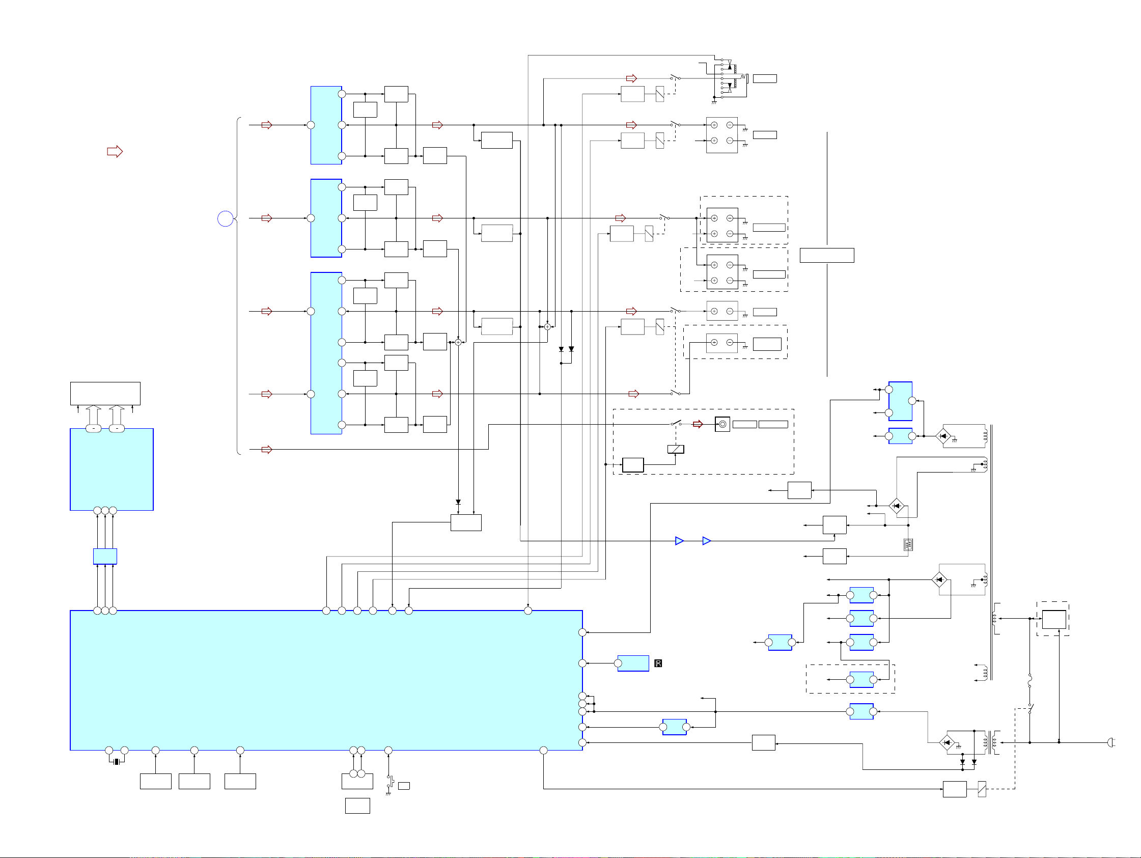
3-2. BLOCK DIAGRAM – DISPLAY/POWER SECTION –
IC501
POWER AMP
+V OUT2
• R-CH is omitted due to same as L-CH.
• Signal Path
FL101
FLUORESCENT
INDICATOR TUBE
F1 F2
14 29
42 31
SEG1-16
GRID1-12
: FM
MAIN
SECTION
(Page 14)
L
SLSL
A
C
SBL
SW
8
IN2
-V OUT2
IC601
POWER AMP
+V OUT2
IN2
8
-V OUT2
IC701
POWER AMP
+V OUT2
8
IN2
+V OUT1
6
IN1
STR-K680/K780
Ver. 1.1
R-CH
RY502
Q608
RELAY
DRIVE
Q509
RELAY
DRIVE
Q508
RELAY
DRIVE
Q708
RELAY
DRIVE
Q560
RELAY
DRIVE
RY601
RY501
RY701
R-CH
R-CH
RY702
R-CH
TM600(1/2)
L
R
TM601(1/2)
L
R
TM602
L
R
TM600(2/2)
TM601(2/2)
J403
12
Q501,502
LIMITER
NF2
9
11
12
Q601,602
LIMITER
NF2
9
11
12
Q701,702
LIMITER
NF2
9
11-V OUT2
2
Q571,572
LIMITER
NF1
5
3-V OUT1
Q503
BOOSTER
Q504
BOOSTER
Q603
BOOSTER
Q604
BOOSTER
Q703
BOOSTER
Q704
BOOSTER
Q754
BOOSTER
Q753
BOOSTER
Q505,506
CURRENT
DETECT
Q605,606
CURRENT
DETECT
Q705,706
CURRENT
DETECT
Q755,756
CURRENT
DETECT
Q507
AF POWER
PROTECT
Q607
AF POWER
PROTECT
Q707
AF POWER
PROTECT
D529
D729
AUDIO OUT
J700
PHONES
FRONT
SURROUND
SURROUND
CENTER
SUB
WOOFER
SUB WOOFER
K680
K680
K780
SPEAKERS
IMPEDANCE USE 6-16Ω
K780
+3.3V
+2.5V
+5V
IC1901
+3.3V
2
REG
+2.5V
5
REG
IC1031
+5V
3 1
REG
4
D804-807
T901
DIN8CLK9STB
7
IC101
BUFFER
59
60
FL_DATA
47
FL_LAT
FL_CLK
X0
82 83
X1101
24MHz
POWER AMP
IC1001
+5V
3 1
REG
AEP,UK,RU
Q860-862
+B
SWITCH
–B
FL101
–20V
RELAY
+B
AUDIO
+7V
AUDIO
–7V
TUNER
+10V
TUNER
+3.3V
Q851,852
–B
SWITCH
Q801
–20V REG
+B
–B
IC821
+7V
1 3
REG
IC822
–7V
3 2
REG
IC1902
+10V
3 1
REG
IC1071
+3.3V
3 1
REG
IC1904
+3.3V
3 1
REG
D811
R803
D920-923
D910-913
Q901
RELAY
DRIVE
E51
S901
VOLTAGE
SELECT
F1
F2
T902
AC
IN
D915D914
RY901
IC100
FL DRIVE
62
66
68
HP RY
REAR RY
FRONT RY
SYSTEM CONTROLLER
IC1101(3/3)
X1
A/D0
38
FUNCTION
KEY
S131-139
A/D1
39
FUNCTION
KEY
S100-108
A/D2
40
FUNCTION
KEY
S110-116
VOL_ENC(B)65VOL_ENC(A)
64
3 1
ENCODER
RV102
MASTER
VOLUME
67
C/SW RY
61
PROTECTOR
POWER KEY
56
S152
46
VACS
?/1
D883
Q881-883
PROTECT
SWITCH
55
HP DETECT
FUSE DETECT
POWER RY
58
SIRCS
AVCC
VCC3
VCC5
RSTX
STOP
IC850(1/2)
IC850(2/2)
57
21
63
IC102
REMOTE
54
35
84
23
77
48
1
CONTROL
RECEIVER
+3.3V(STBY)
IC1111
RESET
1 2
POWER AMP
AUDIO
+5V
+B
AC DET
Q911
STR-K680/K780
1515
STR-K680/K780
Ver. 1.3
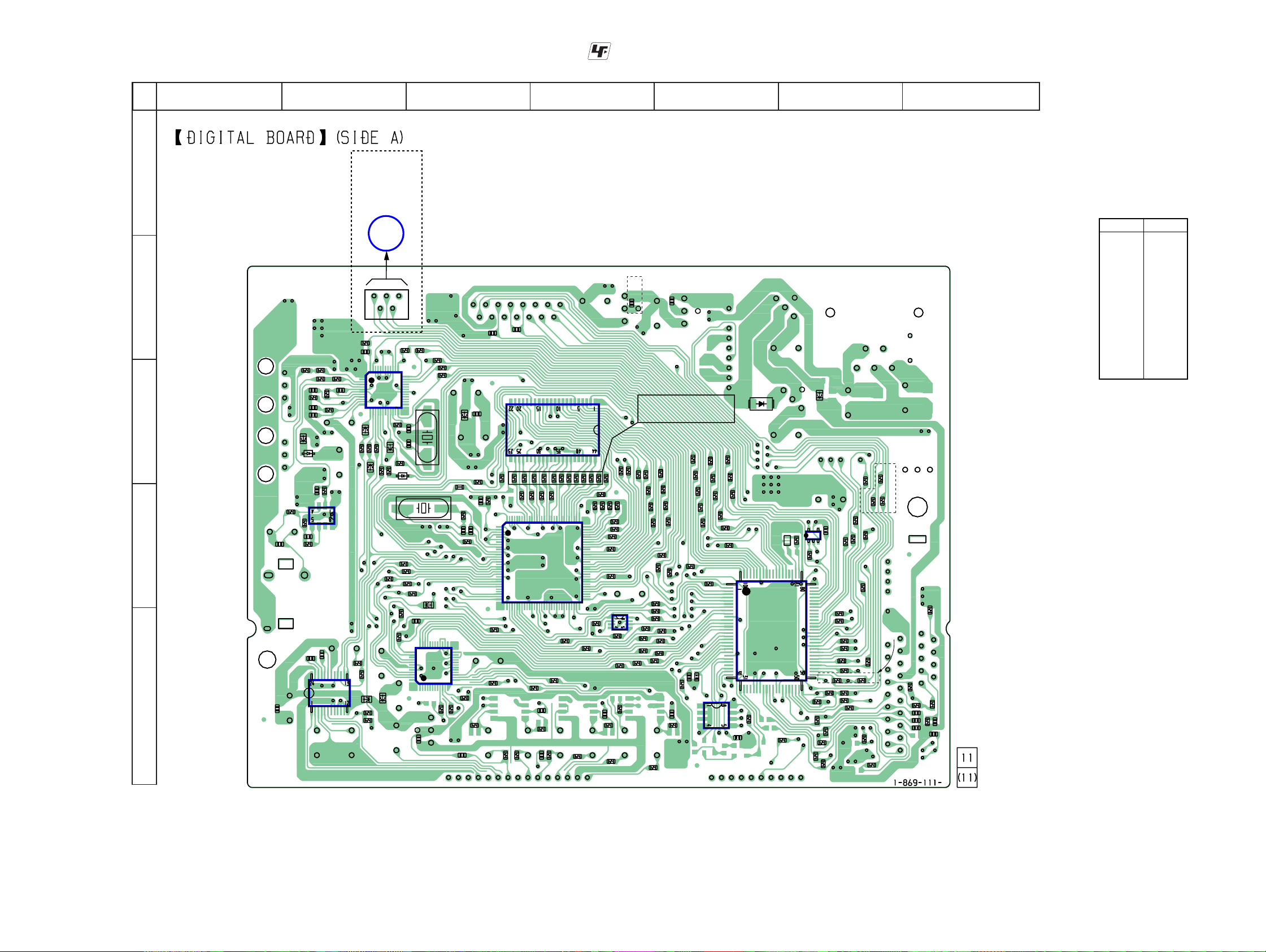
3-3. PRINTED WIRING BOARD – DIGITAL BOARD (SIDE A) –
• See page 13 for Circuit Boards Location.
:Uses unleaded solder.
A
B
C
D
E
12
K780
VIDEO
34567
BOARD
CNS250
(Page 30)
M
1
5
R1356
C1361
C1401
R1352
R1362
R1353
C1302
R1303
R1301
C1303
C1304
FB1306
D1302
C1360
R1358
C1357
R1357
C1408
C1405
IC1401
R1318
C1315
R1363
1
C1301
12
R1304
JR1511
R1305
R1359
IC1303
R1402
FB1405
CNS509
R1316 R1315
48
IC1301
37
13 24
R1310
R1306
R1360
JR1020
R1307
R1308
R1504
R1474
R1401
FB1452
R1407
R1403
36
25
C1310
C1309
FB1305
R1309
D1301
X1502
R1502
R1503
R1506
R1505
R1556
C1494
IC1452
36
37
48
1
C1002
R1313
FB1503
12
R1460
R1312
R1311
X1301
JR1502
25
24
13
R1470
R1461
C1487
FB1502
C1522 R1515
R1523
R1484
C1251
C1516
R1555
C1511
C1521
R1531
R1471
R1501
1
30
C1253
R1541
120
IC1501
31
R1446
R1486
IC1502
R1517
R1552
R1521
R1519
R1509
R1475
R1472
C144
R1445
C1566
R1476
91
R1436
90
61
60
R1508
R1547
R1546
R1571
R1572
R1570
R1574
R1573
R1528
R1527
R1543
R1511
IC1503
R1529
R1510
R1154
R1464
C1432
R1435
R1426
AEP,UK
R1545
R1544
R1152
C1063
R1542
R1162
R1161
R1155
R1520
R1540
R1539
R1538
R1121
R1153
R1466
R1522
R1537
R1532
R1150
R1144
R1143
R1160
R1518
R1536
R1534
R1044
R1149
R1151
C1913
R1554
R1553
R1525
R1136
R1535
R1134
R1533
R1137
C1147
R1168
C1422
R1425
IC1131
R1526
R1135
R1042
R1142
C1148
R1551
R1041
R1140
R1550
R1066
R1549
R1068
R1067
R1120
R1548
R1065
D1001
R1115
R1113
R1119
IC1101
R1098
C1495
IC1111
13
X1101
R1127
R1524
R1635
R1082
R1073
R1458
FB1308
45
C1107
R1105
R1186
R1122
R1123
R1129
R1124
R1094 R1095
R1190 R1128
R1072
R1071
R1459
R1109
R1076
R1088
R1107
R1106
R1059
R1108
EXCEPT
AEP,UK,RU
R1077
AEP,UK,RU
R1058
R1112
R1175
R1035
R1083
R1078
R1180
C1123
C1124
R1179
C1122
C1620
R1636
R1097
R1159
R1605
• Semiconductor
Location
Ref. No.
D1001 C-5
D1301 C-3
D1302 C-2
IC1101 D-5
IC1111 D-6
IC1131 E-5
IC1301 C-2
IC1303 D-2
IC1401 E-2
IC1452 E-3
IC1501 D-4
IC1502 C-4
IC1503 E-4
Location
STR-K680/K780
1616
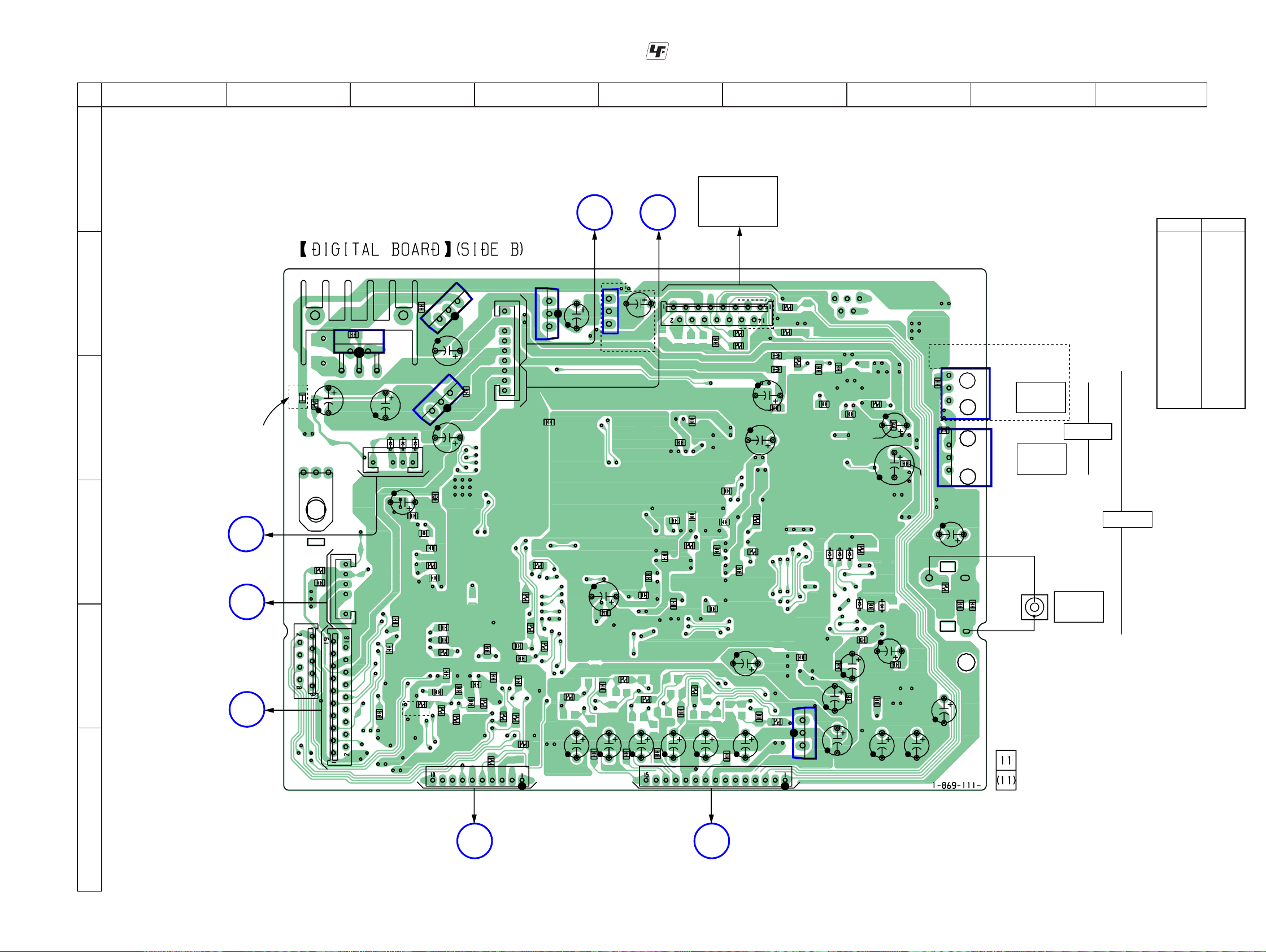
3-4. PRINTED WIRING BOARD – DIGITAL BOARD (SIDE B) –
• See page 13 for Circuit Boards Location.
STR-K680/K780
Ver. 1.3
:Uses unleaded solder.
A
B
C
D
E
F
12
C1905
2
3
MAIN
BOARD
CNP503
(Page 21)
EXCEPT
AEP,UK,RU
A
B
MAIN
BOARD
CNP503
(Page 21)
C
DISPLAY
BOARD
CNS100
(Page 27)
JR1202
R1187
C1143
5
IC1901
R1201
5
CNP504
1
CNS504
C1908
CNS505
C1906
1
C1108
1
D1110
CNP503
C1103
C1102
C1100
C1140
K780
3456789
MAIN
BOARD
1
3
R1493
C1418
C1064
CN504
(Page 21)
C1507
C1506
R1495
C1428
C1569
C1567
C1519
C1513
R1514
C1508
C1505
C1472
C1468
TN1
TUNER UNIT
AEP,UK,RU
CNS508
R1252
C1252
R1251
C1517
C1520
C1515
C1509
C1510
C1514
C1501
C1503
C1504
C1491
R1491
C1547
C1438
CNS501
FB1302
FB1501
C1518
R1513
C1483
C1448
R1260
R1261
R1512
R1492
R1314
C1005
C1313
C1312
C1460
3
1
IC1001
D1112
C1454
C1001
C1314
C1308
D1113
D1114
FB1453
C1450
R1302
C1305
R1198
D1004
C1457
C1406
C1004
C1306
C1359
D1003
C1403
C1404
C1409
IC1352
C1352
C1353
C1358
IC1353
C1402
C1407
C1355
R1355
• Semiconductor
Location
Ref. No.
D1003 D-7
D1004 D-7
D1107 C-3
D1110 C-3
D1111 C-3
D1112 D-6
D1113 D-6
D1114 D-7
K780
IC1001 F-6
IC1031 B-3
IC1071 B-5
IC1352 C-7
3
VIDEO 1
1
3
IN
OPTICAL
IC1353 C-7
IC1901 C-3
IC1902 B-4
IC1904 C-3
Location
VIDEO 2
1
IN
DIGITAL
C1362
C1356
J1301
DVD IN
COAXIAL
D1111
4
C1137
C1138
R1163
IC1031
C1031
3
C1032
3
D1107
C1022
R1189
C1299
C1130
C1129
R1039
C1604
C1120
R1164
1
1
C1021
IC1904
FB1101
C1119
C1118
R1194
CNS502
C1121
C1142
R1167
5
C1139
R1193
R1156
R1096
STANDBY
BOARD
CNP801
(Page 26)
IC1902
1
CNP505
6
8
R1099
R1117
C1254
C1255
C1149
R1157
C1206
R1049
1
3
R1118
D E
C1914
C1525
R1494
C1458
IC1071
AEP,UK,RU
C1502
C1462
C1568
STR-K680/K780
F
MAIN
BOARD
CNP502
(Page 21)
G
1717
MAIN
BOARD
CNP501
(Page 21)
 Loading...