

Page 1
STR-DE575/K502/K502P
SERVICE MANUAL
Ver 1.1 2002. 07
Photo : STR-DE575
Dolby Laboratories Licensing Corporation.
“DOLBY” the double-D symbol ; “AC-3” and “PRO LOGIC”
are trademarks of Dolby Laboratories Licensing Corporation.
SPECIFICATIONS
AUDIO POWER
SPECIFICATIONS
POWER OUTPUT AND
TOTAL HARMONIC
DISTORTION:
With 8 ohm loads, both
channels driven, from 20 20,000 Hz; rated 100
watts
per channel minimum RMS
power, with no more than
0.09% total harmonic
distortion from 250
milliwatts to rated output
(USA model only).
Amplifier section
Rated Power Output at Stereo mode
(8 ohms 20 Hz - 20 kHz,
THD 0.09%)
100 W + 100 W
Reference Power Output
(8 ohms at 1 kHz, THD
0.7%)
1)
Front
: 100 W/ch
1)
: 100 W
Center
Surround
1)
: 100 W/ch
Frequency response
MULTI CH IN, CD,
MD/TAPE, DVD/
LD, TV/SAT,
VIDEO*, AUX:
10 Hz - 50 kHz +0.5/
–2 dB (with sound
field and equalizer
bypassed)
Inputs (Analog)
MULTI CH IN, CD,
DVD/LD, MD/
TAPE, TV/SAT,
VIDEO*, AUX:
Sensitivity: 250 mV
Impedance: 50
kilohms
a)
S/N
: 96 dB (A, 250
b)
)
mV
a) Input short.
b) Weighted network, input level.
Inputs (Digital)
DVD/LD (coaxial):
Sensitivity: –
Impedance: 75 ohms
S/N: 100 dB (A, 20
kHz LPF)
Canadian Model
Australian Model
DVD/LD, TV/SAT
(Optical):
Sensitivity: –
Impedance: –
S/N: 100 dB (A, 20
kHz LPF)
Outputs
EQ
Sampling Frequency
MD/TAPE, (OUT);
VIDEO*,
(AUDIO OUT):
Vo ltage: 250 mV,
Impedance: 10
kilohms
SUB WOOFER:
Vo ltage: 2 V
Impedance: 1
kilohms
PHONES:
Accepts low- and
high-impedance
headphones
±6 dB
48 kHz (TV/SAT, MD/
TAP E OPTICAL IN)
96 kHz (DVD/LD
OPTICAL IN,
COAXIAL IN)
US Model
STR-DE575/K502/K502P
STR-DE575/K502P
E Model
STR-K502P
1) Depending on the sound field settings and
sources, there may be no sound output.
9-873-862-12
2002G1600-1
© 2002.07
— Continued on next page —
FM STEREO FM-AM RECEIVER
Sony Corporation
Home Audio Company
Published by Sony Engineering Corporation
Page 2

STR-DE575/K502/K502P
FM tuner section
Tuning range
Antenna terminals
Intermediate frequency
Sensitivity
Usable sensitivity
S/N
Harmonic distortion at 1 kHz
Separation
Frequency response
Selectivity
AM tuner section
Tuning range
Antenna
Intermediate frequency
Usable sensitivity
87.5 - 108.0 MHz
75 ohms, unbalanced
10.7 MHz
Mono: 18.3 dBf,
2.2 µV/75 ohms
Stereo: 38.3 dBf
22.5 µV/75 ohms
11.2 dBf, 1 µV/75 ohms
Mono: 76 dB
Stereo: 70 dB
Mono: 0.3%
Stereo: 0.5%
45 dB at 1 kHz
30 Hz - 15 kHz +0.5/–2
dB
60 dB at 400 kHz
With 10-kHz tuning
scale:
530 - 1710 kHz
c)
With 9-kHz tuning
scale:
531 - 1710 kHz
c)
Loop antenna
450 kHz
50 dB/m (at 1,000 kHz
or 999 kHz)
S/N
Harmonic distortion
54 dB (at 50 mV/m)
0.5 % (50 mV/m, 400
kHz)
Selectivity
At 9 kHz: 35 dB
At 10 kHz: 40 dB
c) You can change the AM tuning interval to 9
kHz. After tuning in any AM station, turn
off the receiver. Hold down the TUNING +
button and press the ?/1 button. All preset
stations will be erased when you change the
tuning interval. To reset the scale to 10 kHz,
repeat the procedure.
Video section
Inputs
Outputs
*** STR-DE575 only
Video: 1 Vp-p 75 ohms
S-video***:
Y: 1 Vp-p 75 ohms
C: 0.286 Vp-p 75 ohms
Video: 1 Vp-p 75 ohms
S-video***:
Y: 1 Vp-p 75 ohms
C: 0.286 Vp-p 75 ohms
General
System
Tuner section:
PLL quartz-locked
digital synthesizer
system
Preamplifier section:
Low-noise NF type
equalizer
Power amplifier
section:
Pure-complementary
SEPP
Power requirements
120 V AC, 60 Hz
Power consumption
Models of area code U:
220W
In standby condition:
1 W
Models of area code CA:
315 VA
In standby condition:
1 W
AC outlets
1 switched, total
120 W/1A Max
Dimensions
430 × 308.5 × 157.5 mm
(14.5 × 10.4 × 5.3 in.)
including projecting
parts and controls
Mass (Approx.)
7.5 kg (16 lbs. 9 oz.)
7.4 kg (16 lbs. 6 oz.)
Supplied accessories
• FM wire antenna (1)
• AM loop antenna (1)
•
R6 (size-AA) batteries (2)
• STR-DE575 only
• Model of area code U only
- Remote commander RM-U305 (remote) (1)
• Model of area code CA only
- Remote commander RM-PP505 (remote) (1)
• STR-K502 only
• Remote commander RM-U305 (remote) (1)
Design and specifications are subject
to change without notice.
2
Page 3
STR-DE575/K502/K502P
SAFETY CHECK-OUT
After correcting the original service problem, perform the
following safety checks before releasing the set to the customer:
Check the antenna terminals, metal trim, “metallized” knobs, screws,
and all other exposed metal parts for A C leakage. Check leakage as
described below.
LEAKAGE
The AC leakage from any exposed metal part to earth ground
and from all exposed metal parts to any exposed metal part having
a return to chassis, must not exceed 0.5 mA (500 microamperes).
Leakage current can be measured by any one of three methods.
1. A commercial leakage tester, such as the Simpson 229 or RCA
WT -540A. F ollow the manufactur ers’ instructions to use these
instruments.
2. A battery-operated AC milliammeter. The Data Precision 245
digital multimeter is suitable for this job.
3. Measuring the voltage drop across a resistor by means of a
VOM or battery-operated A C voltmeter . The “limit” indication
is 0.75 V, so analog meters must have an accurate low-voltage
scale. The Simpson 250 and Sanwa SH-63Trd ar e examples of
a passive VOM that is suitable. Nearly all battery operated
digital multimeters that have a 2V AC range are suitable. (See
Fig. A)
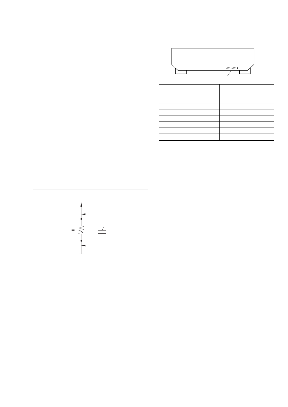
MODEL IDENTIFICATION
— BACK PANEL —
MODEL
DE575 : US
DE575 : Canadian
K502P : US
K502P : Canadian
K502P : Australian
K502P : Singapore
K502P : Mexican
K502 : US
Parts No.
PARTS No.
4-232-240-0s
4-232-240-1s
4-232-240-3s
4-232-240-4s
4-232-240-5s
4-232-240-6s
4-232-240-7s
4-232-240-8s
To Exposed Metal
Parts on Set
AC
0.15 µF
Fig. A. Using an AC voltmeter to check AC leakage.
1.5 kΩ
Earth Ground
Voltmeter
(0.75 V)
SAFETY-RELATED COMPONENT WARNING!!
COMPONENTS IDENTIFIED BY MARK 0 OR DOTTED LINE WITH
MARK 0 ON THE SCHEMATIC DIAGRAMS AND IN THE PARTS
LIST ARE CRITICAL TO SAFE OPERATION. REPLACE THESE
COMPONENTS WITH SONY PARTS WHOSE PART NUMBERS
APPEAR AS SHOWN IN THIS MANUAL OR IN SUPPLEMENTS
PUBLISHED BY SONY.
ATTENTION AU COMPOSANT AYANT RAPPORT
À LA SÉCURITÉ!
LES COMPOSANTS IDENTIFÉS PAR UNE MARQUE 0 SUR LES
DIAGRAMMES SCHÉMATIQUES ET LA LISTE DES PIÈCES SONT
CRITIQUES POUR LA SÉCURITÉ DE FONCTIONNEMENT. NE
REMPLACER CES COMPOSANTS QUE PAR DES PIÈSES SONY
DONT LES NUMÉROS SONT DONNÉS DANS CE MANUEL OU
DANS LES SUPPÉMENTS PUBLIÉS PAR SONY.
3
Page 4

STR-DE575/K502/K502P
1. GENERAL ··········································································5
2. TEST MODE ······································································ 7
3. DIAGRAMS
3-1. Circuit Boards Location ..................................................... 9
3-2. Block Diagrams ................................................................ 10
3-3. Printed Wiring Board – Digital Section – ........................ 12
3-4. Schematic Diagram – Digital Section (1/3) – .................. 13
3-5. Schematic Diagram – Digital Section (2/3) – .................. 14
3-6. Schematic Diagram – Digital Section (3/3) – .................. 15
3-7. Printed Wiring Board – Main Section – ........................... 16
3-8. Schematic Diagram – Main Section (1/3) – ..................... 17
3-9. Schematic Diagram – Main Section (2/3) – ..................... 18
3-10. Schematic Diagram – Main Section (3/3) – ..................... 19
3-11. Printed Wiring Board – Display Section – .......................20
3-12. Schematic Diagram – Display Section – .......................... 21
3-13. Printed Wiring Board – V ideo Section – .......................... 22
3-14. Schematic Diagram – Video Section – ............................. 23
3-15. Schematic Diagram – Power Section – ............................ 24
3-16. IC Block Diagrams ........................................................... 25
3-17. IC Pin Function Description .............................................27
TABLE OF CONTENTS
• Main Section .................................................................. 10
• Display/Power Section................................................... 11
4. EXPLODED VIEWS
4-1. Front Panel Section .......................................................... 29
4-2. Chassis Section ................................................................. 30
5. ELECTRICAL PARTS LIST ·······································32
4
Page 5
SECTION 1
GENERAL
STR-DE575/K502/K502P
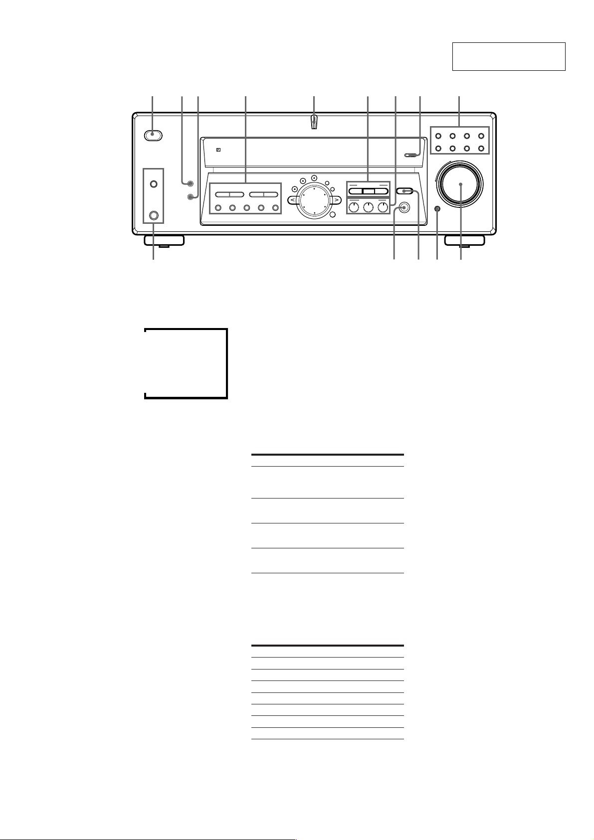
This section is extracted
from instruction manual.
1
23 4 5 6 7
/
SPEAKERS
PHONES
DISPLAY
DIMMER
1 ?/1 switch
Press to turn the receiver on and off.
2 DISPLAY button
Press repeatedly to change the information on the
display window as follows:
Index name of the component or the preset station*
FUNCTION button indication or frequency**
Sound field applied to the program source
* Index name appears only when you have assigned one to the
component or preset station (see page 41). Index name does not
appear when only blank spaces have been entered, or it is the
same as the function button.
** Frequency appears only when the tuner is selected.
m
m
m
3 DIMMER button
Press repeatedly to adjust the brightness of the
display. When you want to turn off the display, set in
the “DIM.RANGE” parameter in the SET UP menu
(page 45).
4
The following buttons operate the built-in tuner. For
details, see “Receiving Broadcasts” starting from page 38.
PRESET TUNING +/– buttons
Scan all preset stations.
TUNING +/- buttons
Scan all the available radio stations.
MEMORY button
Press to memorize a preset station.
SHIFT button
Selects a memory page for preset stations.
FM MODE button
If “STEREO” flashes in the display and the FM stereo
reception is poor, press this button. You will not have
the stereo effect but the sound is improved.
FM button
Selects the FM band.
AM button
Selects the AM band.
5
MULTI CHANNEL DECODING indicator
This indicator lights up when the unit is decoding
signals recorded in a multi channel format.
6 Use the CINEMA STUDIO EX buttons to enjoy the
CINEMA STUDIO EX sound effects.
A/B/C buttons
Press to activate the CINEMA STUDIO EX A, B or C
sound field (page 29).
MULTI CHANNEL DECODING
LEVEL
PRESET
– + – +
TUNING
MEMORY SHIFT FM MODE FM AM
TUNING
SURR
EQ
7 Use the SOUND FIELD buttons to enjoy surround
sound. For details, see “Enjoying Surround Sound”
starting from page 27.
A.F.D. button / indicator
Press to set the receiver to automatically detect the
type of audio signal being input and perform proper
decoding (if necessary).
MODE button / indicator
Press to activate the sound field selection mode (page 28).
2CH button / indicator
Press to output sound from only the front (left and
right) speakers.
8 INPUT MODE button
Press to select the input mode for your digital
components (DVD/LD, TV/SAT).
Each press switches the input mode of the currently
selected component.
Select To
AUTO
DIGITAL (OPTICAL) Specify the digital audio signals
DIGITAL (COAXIAL) Specify the digital audio signals
ANALOG Specify the analog audio signals
Note
If 96 kHz digital signal is input, the tone, sound field and
surround parameters do not function.
Give priority to digital signals
when there are both digital and
analog connections. If there are no
digital signals, analog is selected
input to the DIGITAL OPTICAL
input jacks
input to the DIGITAL COAXIAL
input jacks (DVD/LD only)
input to the AUDIO IN (L and R)
jacks
9 Function buttons
Press one of the buttons to select the component you
want to use.
To select Press
VCR VIDEO
DVD or LD player DVD/LD
TV or satellite tuner TV/SAT
MD or Tape deck MD/TAPE
CD player CD
Built in tuner TUNER
An audio component AUX
After selecting the component, turn on the component
you selected and play the program source.
• After selecting VCR, DVD player, or LD player, turn on the
TV and set the TV’s video input to match the component
you selected.
SET UP
NAME
ENTER
CINEMA STUDIO EX
A
SOUND FIELD
A.F.D.
BC
MODE 2CH
89
VIDEO 1
VIDEO 2CDDVD/LD
TV/SAT
MD/TAPE
INPUT MODE
EQUALIZER
MULTI CH IN
MUTING
qdqf
0 MASTER VOLUME control
After turning on the component you selected, rotate to
adjust the volume.
qa MUTING button
Press to mute the sound. MUTING appears in the
display when the sound is muted.
qs EQUALIZER button
Press to turn the equalizer on or off. The EQ indicator
in the display lights when the equalizer is turned on.
When you adjust the equalizer using the EQ
parameters (page 36) the settings are stored
automatically and can be reproduced wherever you
turn on the equalizer.
• The equalizer is not compatible with 96 kHz digital audio
signals and during MULTI CH IN input.
z When you want to listen to an analog source
without any digital processing
Do the following to bypass the sound field and equalizer
circuits.
1 Press 2CH.
2 Press EQ to turn off the EQ indicator.
The result will be a sound that is highly faithful to the
program source.
qd MULTI CH IN button
Press to enjoy the audio source connected to the
MULTI CH IN jacks with the video from the selected
component. Press again to cancel MULTI CH IN.
• When the MULTI CH IN is selected, the tone, equalizer,
and sound field effects do not function.
qf SPEAKERS button
Press SPEAKERS button to ON.
PHONES jack
Connects headphones.
• When you connect the headphones, no sound will come
from the speakers.
–
TUNER
MASTER VOLUME
+
0qaqs
AUX
5
Page 6
STR-DE575/K502/K502P
/
SPEAKERS
PHONES
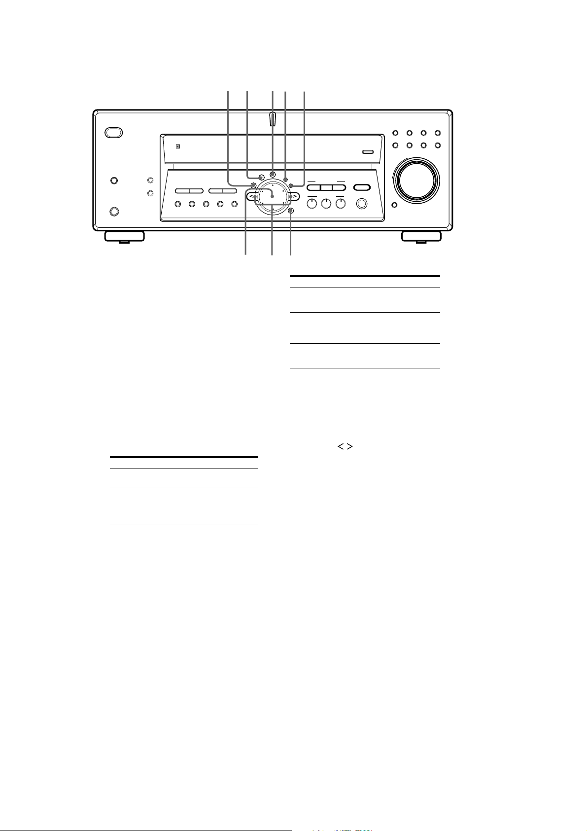
qg EQ button
Press to activate the equalizer parameters (page 36).
The indicator on the button lights up and you can
adjust the various equalizer parameters.
qh SURR button
Press to activate the surround parameters (page 34).
The indicator on the button lights up and you can
adjust the various surround parameters (effect level,
wall type, etc.).
qj LEVEL button
Press to activate the speaker level parameters (page
35). The indicator on the button lights up and you can
adjust the various speaker level parameters (front
balance, surround balance, etc.).
qk SET UP button
Press to activate the setup mode, then use the cursor
buttons (wa) to select any of the following indications.
You can then make various settings using the jog dial
(ws).
When you select You can
Speaker type Specify the type of speakers.
Speaker setup Specify the front, center,
DISPLAY
DIMMER
qg
PRESET
– + – +
TUNING
MEMORY SHIFT FM MODE FM AM
(page 17)
surround speaker sizes, the
surround speaker position, and
whether or not you are using a
sub woofer. (page 17)
TUNING
qh qj qk ql
MULTI CHANNEL DECODING
LEVEL
SURR
EQ
SET UP
NAME
ENTER
w;waws
When you select You can
Speaker Distance Specify the front, center, and
MULTI CH IN video input Specify the video input to be
Dimmer range Specify the display to turn off
ql NAME button
Press to activate the name function and enter names
for preset stations and program sources (page 43).
w; ENTER button
Press to enter individual characters for the preset
station and program source names.
wa Cursor buttons (
Press to select various speaker level, surround, and
equalizer parameters (etc.).
ws Jog dial
Turn to adjust the selected speaker level, surround,
and equalizer parameters (etc.).
CINEMA STUDIO EX
A
SOUND FIELD
A.F.D.
BC
MODE 2CH
VIDEO 1
MD/TAPE
INPUT MODE
EQUALIZER
MULTI CH IN
surround speaker distances.
(page 19)
used with the audio signals from
the MULTI CH IN jacks. (page
45)
when you press the DIMMER
button several times. (page 45)
–
MUTING
/ )
VIDEO 2CDDVD/LD
TUNER
MASTER VOLUME
+
TV/SAT
AUX
6
Page 7
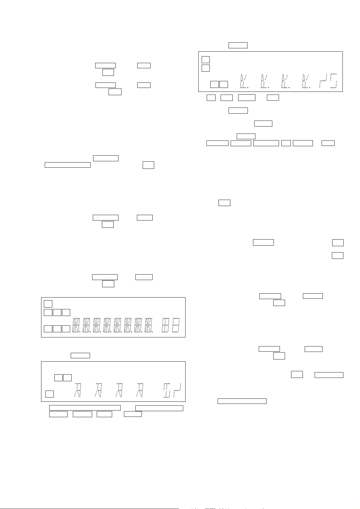
SECTION 2
SL
C
SR
SP.OFF
( ( ( ) ) )
DIGITAL
OPT MULTI CH IN
DTS MONO MEMORY
NEWSEQ
dB
Hz
ft.
TEST MODE
STR-DE575/K502/K502P
FACTORY PRESET MODE
* All preset contents are reset to the default setting.
* Procedure:
While depressing the VIDEO and the 2CH buttons simultaneously, press the po wer
button to turn on the main power .
?/1
The message FACTORY appears and switch off the set.
While depressing the VIDEO and the 2CH buttons simultaneously, press the power
button again. The message
?/1
FA CTOR Y appears and the present contents are reset to the def ault
values.
AM CHANNEL STEP 9 KHZ/10 KHZ
SELECTION MODE
* Either the 9 kHz step or 10 kHz step can be selected for the AM
channel step.
* Procedure:
Set the FUNCTION to AM. Turn off the main power.
While depressing the TUNING+ button or the
PRESET TUNING+ button, press the power
button to turn
?/1
on the main power. Either the message 9 k STEP or 10 k STEP
appears. Select the desired step.
* For US/Canadian/E model only
DSP VERSION DISPLAY MODE
* DSP version is displayed.
* Procedure :
While depressing the MD/TAPE and the A.F.D buttons simultaneously, press the po wer
button to turn on the main power .
?/1
“ DSP ”and the version are displayed.
FLUORESCENT INDICATOR TUBE TEST MODE
* All fluorescent segments are tested. When this test is activated,
all segments turn on at the same time, then each segment turns on
one after another.
* Procedure:
While depressing the MD/T APE and the SHIFT b uttons simultaneously, press the po wer
1. All segments turn on.
SLEEP
SW
SP.OFF
LSLCR
( ( ( L F E ) ) )
SSR
DIGITAL
OPT COAX MULTI CH IN
PRO LOGIC DTS MPEGSTEREO MONORDS MEMORY
D
D
All LED turn on.
2. Press the VIDEO button, confirm display
D
SLEEP
SW
LR
L F E
S
D
PRO LOGIC MPEGSTEREO RDS
COAX
MULTI CHANNEL DECODING (b lue), Digital Cinema Sound ,
LEVEL , SET UP , A.F.D and MODE LED turn on.
button to turn on the main power .
?/1
dB
kHz
mft.
MHz
k
m
MHz
MUTINGINFONEWSTAEQD.RANGE
MUTINGINFOTAD.RANGE
3. Press the VIDEO button, confirm display
EQ , SUR , NAME and 2CH LED turn on.
4. Press the VIDEO button, All segments turn off.
5. Every pressing of the VIDEO button turns on each
segment and LED one after another in the same order.
(Not only the VIDEO button, but also the other buttons such as
DVD/LD , TV/SAT , MD/TAPE , CD , TUNER and AUX can
be used.)
SOUND FIELD CLEAR MODE
* The preset sound field is cleared when this mode is activated.
Use this mode before returning the product to clients upon
completion of repair.
* Procedure:
While depressing the SOUND FIELD MODE button, press the
power
button to turn on the main power. The message
?/1
SURR. CLR. appears and initialization is performed.
DEMONSTRATION MODE
* Demonstration is performed.
* Procedure :
While depressing the SET UP button, press the power
?/1
button. The message appears and demonstration is performed.
* To finish DEMONSTRATION MODE, press the power
?/1
button while the introduction message appears in the display.
SOFTWARE VERSION DISPLAY MODE
* The software version is displayed.
* Procedure:
While depressing the TUNER and the SHIFT buttons
simultaneously, press the power
button to turn on the main
?/1
power . The model name, destination and the software version are
displayed.
KEY CHECK MODE
* Button check
* Procedure:
While depressing the VIDEO and the SHIFT buttons
simultaneously, press the po wer
power.
“REST 36” appears.
Every pressing of any button other than ?/1 and SPEAKERS
counts down the buttons. The b uttons which are already counted
once are not counted again. When all buttons are pressed “REST
00” appears.
When MASTER VOLUME is rotated in clockwise direction,
“VOL MIN”, “VOL 1” to “VOL 48”, “VOL MAX” appear.
button to turn on the main
?/1
7
Page 8
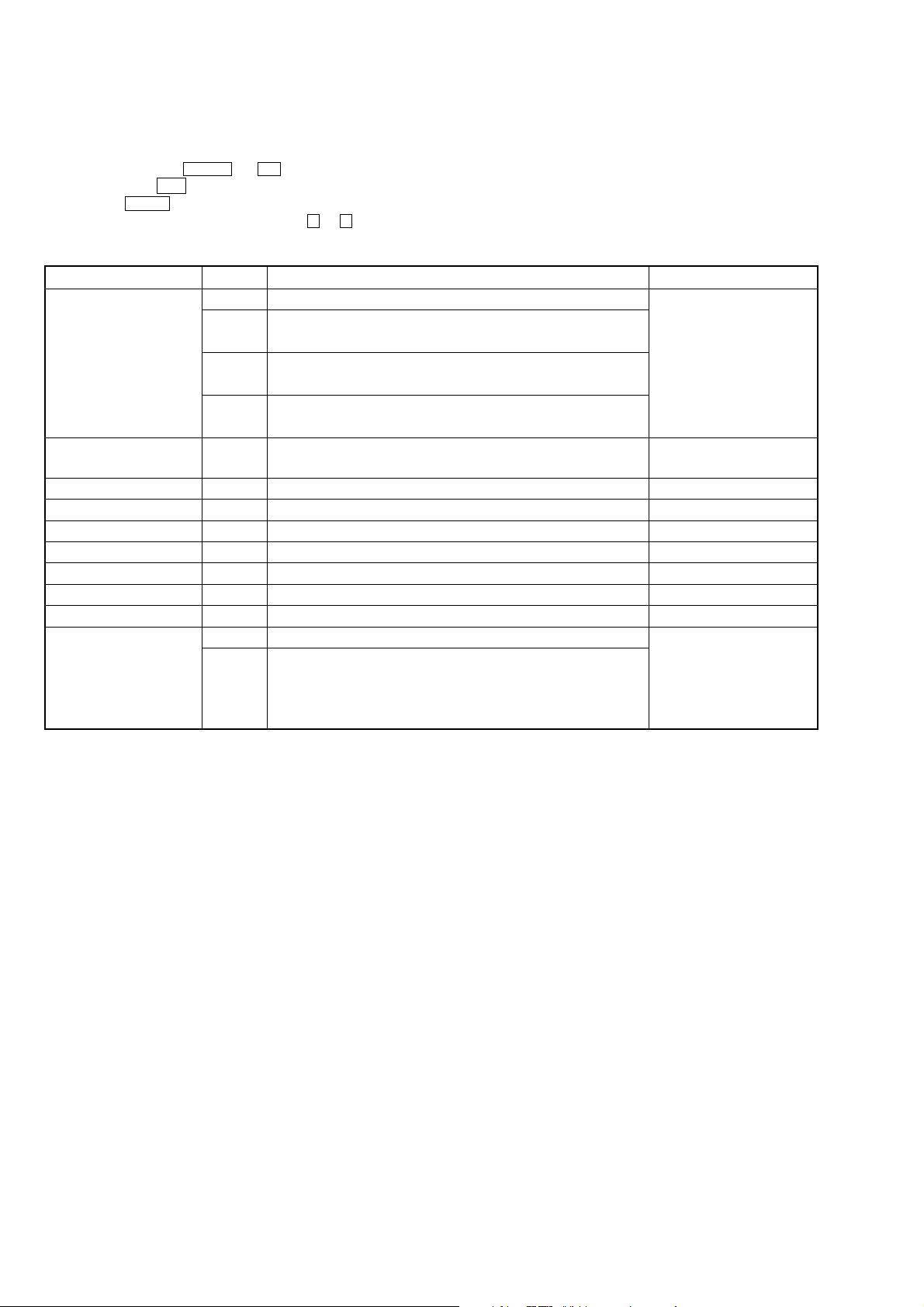
STR-DE575/K502/K502P
DSP TEST MODE
* DSP tests are performed.
* Procedure :
1. While depressing the LEVEL and CD buttons simultaneously,
press the power ?/1 Button to turn on the main power.
2. Press the NAME button.
3. Select the item by pressing Cursor button ( < or > ).
4. Select the function by turning Jog dial if selection is necessary.
Items
SWAP
DSP communication
Bass Management
Main Speaker cut off Freq.
LFE cut off Freq.
Co-ef. Read Address
Co-ef. Read Data
Co-ef. Write Address
Co-ef. Write Data
SRAM
Function
NORM
ALL
C SW
SLSR
–
–
–
–
–
–
–
–
OFF
ON
Description
Normal channel output
Left input t Front Left, Surround Left, Center channel output
Right input t Front Right, Surround Right, Sub Woofer channel output
Left input t Center channel output
Right input t Sub Woofer channel output
Left input t Surround Left channel output
Right input t Surround Right channel output
When this item is selected the message will be displayed “ OK ” if the
checking is correct. “ ERROR ” will be displayed in a case of an error.
Not used for service
Not used for service
Not used for service
Not used for service
Not used for service
Not used for service
Not used for service
“ RAMC. OFF ” will be displayed in a case of no checking.
By turning Jog dial “ RAMC. EXE ” will be displayed during the
checking.
After a while “ RAMC. PASS ” will be displayed if the checking is good.
“ RAMC. NG ” will be displayed if an error occurs.
Remark
Selection of setting
output channels
Checking communication
between DSP and microcom
Checking communication
between DSP and SRAM
8
Page 9
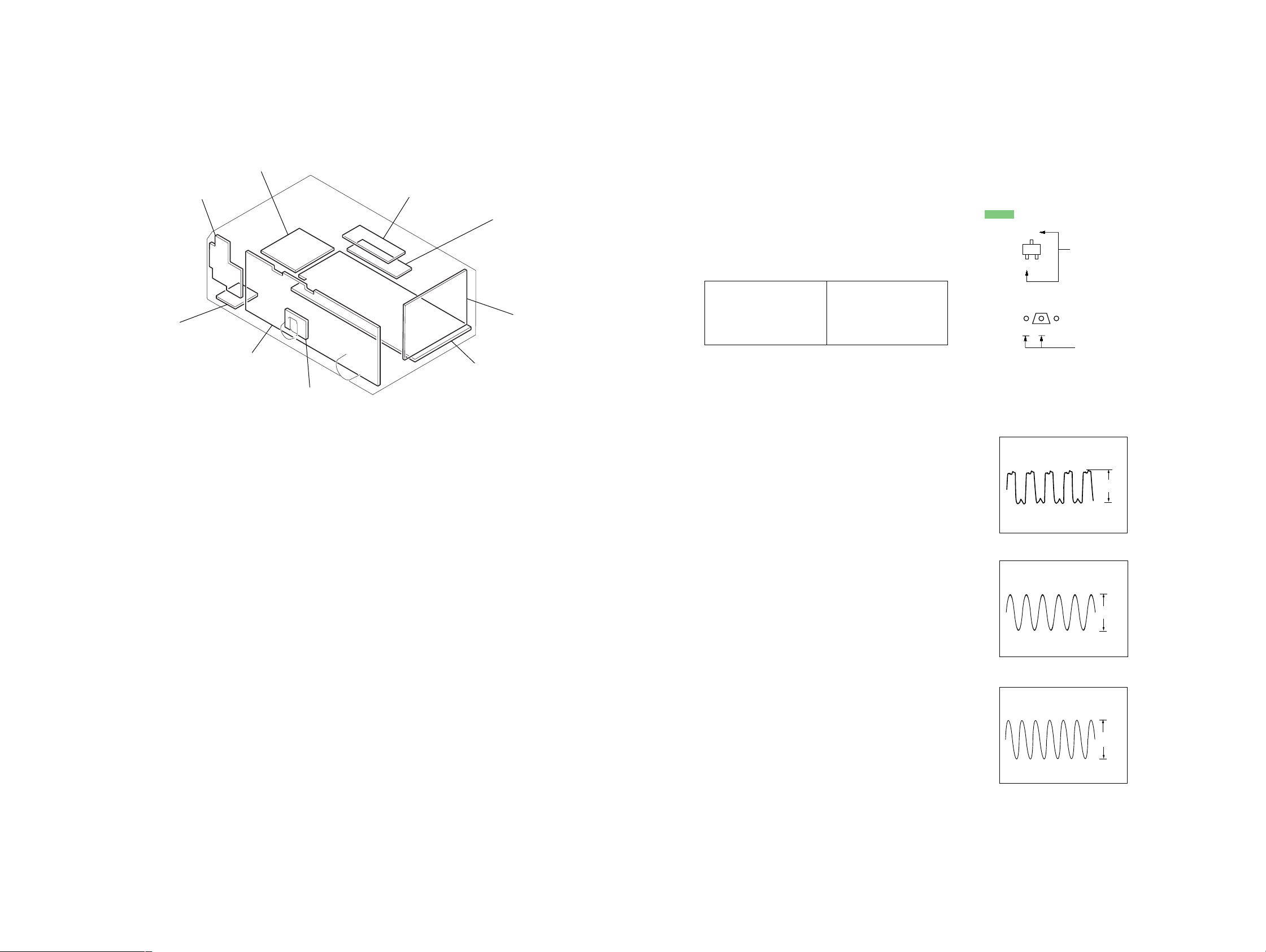
SECTION 3
DIAGRAMS
STR-DE575/K502/K502P
3-1. CIRCUIT BOARDS LOCATION
STBY board
POWER SWITCH board
HEADPHONE board
DISPLAY board
JOG board
VIDEO board
S-VIDEO board
DIGITAL board
MAIN board
THIS NOTE IS COMMON FOR PRINTED WIRING
BOARDS AND SCHEMATIC DIAGRAMS.
(In addition to this necessary note is printed in each
block.)
For schematic diagrams.
Note:
• All capacitors are in µF unless otherwise noted. pF: µµF
50 WV or less are not indicated except for electrolytics
and tantalums.
• All resistors are in Ω and 1/
specified.
• % : indicates tolerance.
f
•
• 2 : nonflammable resistor.
• 1 : fusible resistor.
• C : panel designation.
• A : B+ Line.
• B : B– Line.
• H : adjustment for repair.
• Voltages and waveforms are dc with respect to ground
• Voltages are taken with a VOM (Input impedance 10 MΩ).
• Waveforms are taken with a oscilloscope.
• Circled numbers refer to waveforms.
• Signal path.
• Abbreviation
: internal component.
Note:
The components identified by
mark 0 or dotted line with mark
0 are critical for safety.
Replace only with part number
specified.
under no-signal (detuned) conditions.
No mark : FM
Voltage variations may be noted due to normal production tolerances.
F : FM
J : CD (ANALOG)
c : DVD (DIGITAL)
CND : Canadian model
MY : Malaysia model
SP : Singapore model
MX : Mexican model
AUS : Australian model
W or less unless otherwise
4
Note:
Les composants identifiés par
une marque 0 sont critiques
pour la sécurité.
Ne les remplacer que par une
pièce portant le numéro spécifié.
For printed wiring boards.
Note:
• X : parts extracted from the component side.
a
•
•
• : Pattern from the side which enables seeing.
: Through hole.
f
: internal component.
C
Q
B
E
B
CE
These are omitted.
These are omitted.
• Waveform
DIGITAL Board
1 IC1101 wa (XOUT)
4.4Vp-p
12.288MHz
DIGITAL Board
2 IC1201 9 (MCLK)
3.3Vp-p
13.3MHz
DIGITAL Board
3 IC1601 id (XI)
2.8Vp-p
20MHz
99
Page 10
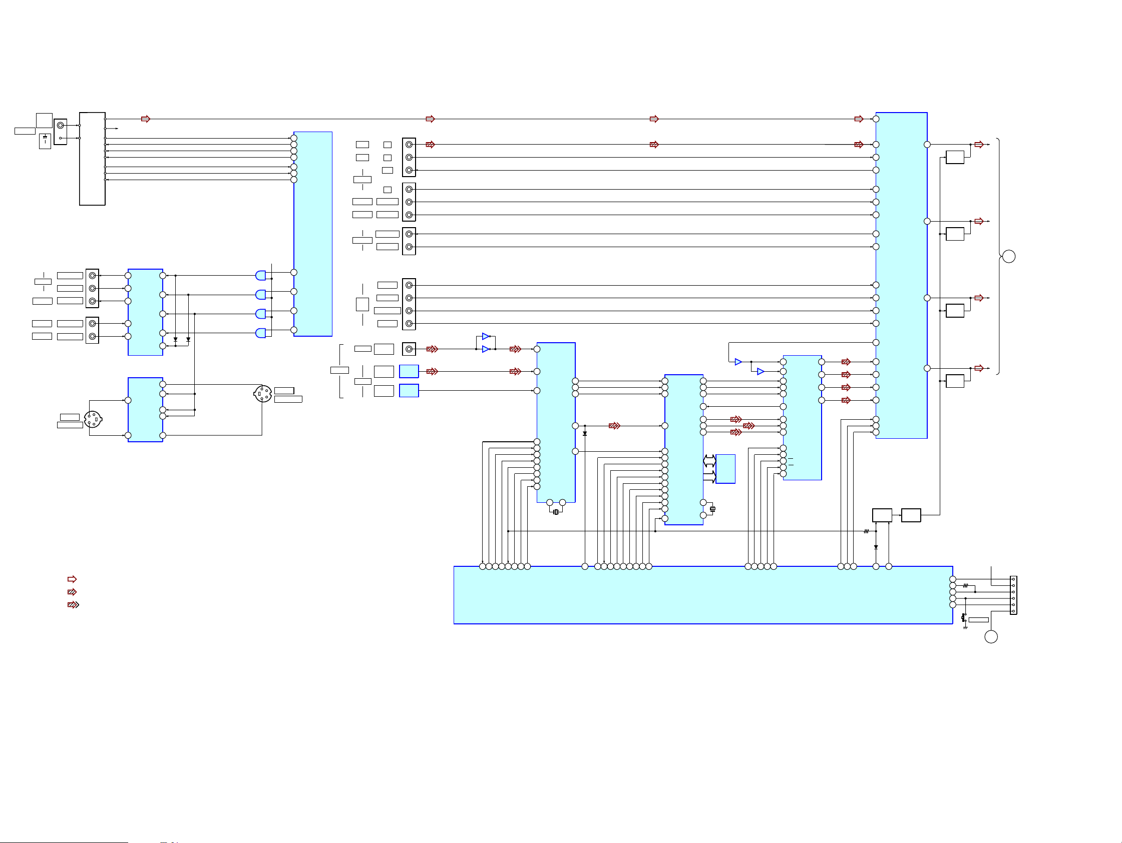
STR-DE575/K502/K502P
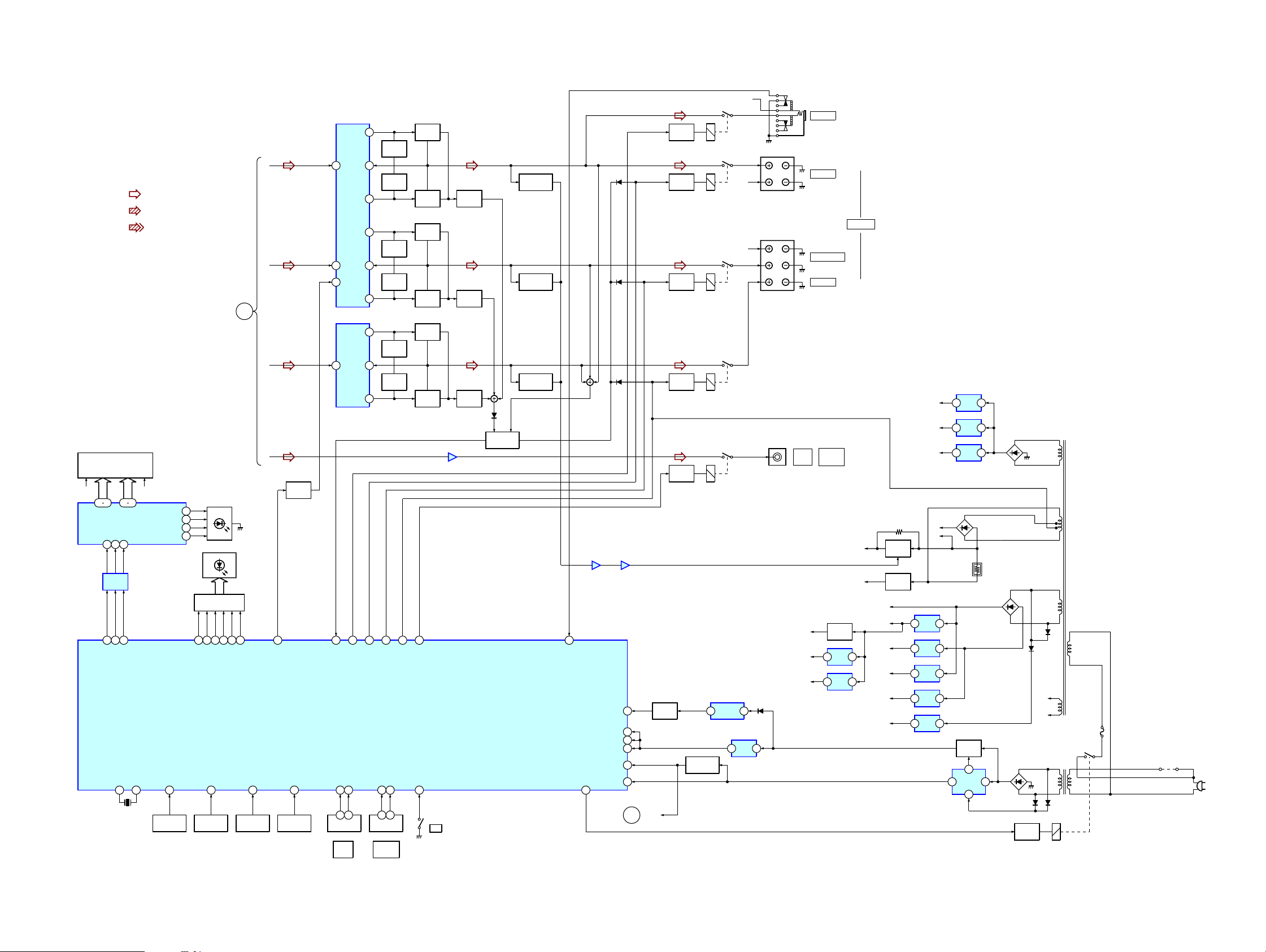
3-2. BLOCK DIAGRAMS – MAIN SECTION –
ANTENNA
FM
75 Ω
COAXIAL
AM
VIDEO
MONITOR
TV/SAT
DVD/LD
— TM301 —
TUNER UNIT
VIDEO OUT
VIDEO IN
VIDEO OUT
VIDEO IN
VIDEO IN
J1802
DVD/LD
S VIDEO IN
ANALOG SOUND
PROC.
L CH
FM
AM
STEREO
MUTING
J200
J201
R CH
DATA
CLOCK
TUNED
R-CH
DO
CE
VIDEO SELECT
IC103
IC103
15
SW1
14
V1 OUT
13
V1 IN
SW2
M OUT
TV
LD
Y SWITCH
VIN3
VIN1
IC1802
MUTING1
MUTING2
VOUT1
10
SW3
4
SW4
6
SW5
2
5VOUT2
SW1
2
11
4
10
1
5
3
Y
1
C
12
IC1603
3
IC1603
6
IC1603
8
IC1603
11
Y
C
+5V
1
2
4
5
9
10
12
13
J1804
MONITOR
S VIDEO OUT
SYSTEM CONTROL.
IC1601(1/3)
76
DO
86
SDATA
78
SCLK
87
SLATCH
73
STEREO
74
TUNED
75
MUTING
91
MUTING2
90
MUTING1
89
S2
88
S1
DIGITAL
CD
AUX
MD/TAPE
TV/SAT
DVD/LD
VIDEO
MULTI
CH IN
COAXIAL
OPTICAL
IN
IN
OUT
IN
AUDIO IN
AUDIO IN
AUDIO OUT
AUDIO IN
FRONT
SURROUND
SUB WOOFER
CENTER
DVD/LD
IN
DVD/LD
IN
TV/SAT
IN
J402
J403
J404
J401
J1101
IC1104
IR LINK
DET
IC1105
IR LINK
DET
IC1102
35
IC1102
62
DIGITAL AUDIO
5
DIN2
3
DIN0
4
DIN1
35
DO
36
DI
38
CLK
37
CE
34
ERROR
17
XSTATE
48
XMODE
47
CKSEL1
I/F RECEIVER
IC1101
CK OUT
XIN XOUT
22 21
X1101
12.288MHz
LRCK
DATAO
AUDIO CODEC
IC1502
67
AUDIO DSP
IC1201
22
SCK OUT
BCKO1
SDO1
SDO2
SDO3
MCLK1
MCLK2
14
20
19LRCKO
18SDI1
23
24
25
IC1202
SRAM
9
X1201
13.5MHz
12
13
BCK
14
15
16
24AUDIO
KFSI0
29
BCKI2
28
LRCK2
30
SDI2
69
GP8
68
GP9
35
HD OUT
33
HD IN
34
HCLK
36
HCS
32
HACN
PM
113
56
BST
2
XRST
59
EXLOCK
IC1502
21
IC1501
29
L OUT1
L OUT2
L OUT3
R OUT3
27
25
23
24
LIN-
30
LIN+
39
MCLK
4
BCK
5
LRCK
9
SDTO
6
SDTI1
7
SDTI2
8
SDTI3
43
CDT1
42
CCLK
41
CS
17
PD
3
SMUTE
1
L IN8
2
L IN9
3
L IN10
67
L REC3
71
L IN7
70
L IN6
69
L IN5
61
L REC1
62
L IN1
11
AL IN
13
ASL IN
16
ASW IN
15
AC IN
9
AL OUT
27
DL IN
29
DSL IN
31
DC IN
32
DSW IN
20
DATA
21
CLOCK
22
LATCH
Q1601,1602
MUTING
CONT
IC201
SL OUT
SW OUT
Q379
MUTING
SWITCH
L OUT
C OUT
51
MUTING
Q361
47
MUTING
Q362
L
SL
SL
A
39
MUTING
Q363
35
MUTING
Q364
C
SW
• R-CH is omitted due to same as L-CH.
• Signal Path
: FM
: CD(ANALOG)
: DVD (DIGITAL)
98 97 95 96 99 100 94 1
DO
93
DI
CE
CLK
ERROR
XMODE
XSTATE
CKSEL1
1010
DATA0
S139
SPEAKERS
+3.3V
FLASH 1
FLASH 2
RESET
CNS3
MD0
VDD
FOR
MD2
FLASH
PROGRAMMING
15
DATA
16CE14
24
ANA/DIG
21
F.MUTING
SP SW/FLASH 1
FLASH 2
49MD0
MD1
50
MD2
51
28
27
CLK
20
4
5
7PM3
HCLK
6
BST
HCS
XRST
HACN
SYSTEM CONTROL
IC1601(2/3)
2
18
19
GP9
HD IN
HD OUT
10
12
13CS8PD9
SCL
CDT1
SMUTE
B
Page 11
– DISPLAY/POWER SECTION –
STR-DE575/K502/K502P
• R-CH is omitted due to same as L-CH
• Signal Path
FL101
FLUORESCENT
INDICATOR TUBE
FL1 FL2
14 29
42 31
SEG1-16
GRID1-12
DIN8CLK9STB
7
BUFFER
IC101
61
62
DIN
CLK63STB
X1
X0
82 83
X1601
20.0MHz
: FM
: CD(ANALOG)
: DVD (DIGITAL)
LED DRIVE
IC100
LEVEL LED
NAME LED
SUR LED
SETUP LED
AD0
38
FUNCTION
KEY
S100-117
2
3
1
4
D106-109
D100-105
LED DRIVE
Q100-105
40
32
AFD LED
MULTI CH LED
39
FUNCTION
KEY
S101-103,
S105-107
31
AD1
30
2CH LED
MODE LED
25
A
29
EQ LED
DCS LED
FUNCTION
S118-125
R-CH
POWER AMP
IC701
+V OUT2
12
L
SLSL
C
SW
POWER
MUTING
Q747,748
22
AC MUTING
AD2
40
KEY
AD3
41
FUNCTION
KEY
S128-137
8
IN2
-V OUT2
6
IN1
1
MUTING
-V OUT1
POWER AMP
IC501
+V OUT
1
IN+
67
68
PROTECT
SYSTEM CONTROL
IC1601(3/3)
JOG+
JOG-
58
57
3 1
ENCODER
RV101
JOG
DIAL
NF2
9
11
2+V OUT1
NF1
5
3
6
IN-
2
5-V OUT
72
FRONT RY
HEADPHONE RY
ENCODER
RV102
MASTER
VOLUME
70
VOL+60VOL-
3 1
LIMITER
Q701
LIMITER
Q702
LIMITER
Q651
LIMITER
Q652
LIMITER
Q501
LIMITER
Q502
REAR RY
59
71
CENTER RY
BOOSTER
Q703
BOOSTER
Q704
BOOSTER
Q653
BOOSTER
Q654
BOOSTER
Q503
BOOSTER
Q504
69
WOOFER RY
POWER KEY
56
S138
?/1
IC601
21
POWER RY
66
D731
D733
D734
IC601
57
SIRCS
AVCC
VCC3
VCC5
RESET
STOP
BUFFER
54
Q1603
35
84
23
77
47
RESET
B
AF POWER
PROTECT
CURRENT
DETECT
Q705,706
CURRENT
DETECT
Q655,656
CURRENT
DETECT
Q505,506
D721
PROTECT
SWITCH
IC401
5
Q722,723,725
7
Q740
AF POWER
PROTECT
Q640
AF POWER
PROTECT
Q540
26
HP DETECT
RELAY
DRIVE
Q790
RELAY
DRIVE
Q710
RELAY
DRIVE
Q610
RELAY
DRIVE
Q550
RELAY
DRIVE
Q560
RY791
RY701
RY601
RY501
RY560
RESET
Q1604,1605
1
IC102
REMOTE
CONTROL
RECEIVER
R-CH
R-CH
2
IC1904
+3.3V
3 1
REG
TM602
L
R
TM601
SR
SL
C
J405
D1911
AUDIO
OUT
+3.3V
TUNER
+3.3V
AUDIO
+5V
J791
PHONES
FRONT
SURROUND
CENTER
SUB
WOOFER
+3.3V REG
3 1
3 1
POWER AMP
Q471
IC803
+3.3V
REG
IC1503
+5V
REG
SPEAKERS
-B
FL101
-30V
RELAY
+B
AUDIO
+7V
AUDIO
-7V
VIDEO
+5V
VIDEO
-5V
TUNER
+12V
-B SW
Q691,692
-30V REG
Q801
+3.3V
+2.5V
+5V
IC801
+7V
1 3
REG
IC802
-7V
3 2
REG
IC807
+5V
3 1
REG
IC804
-5V
3 2
REG
IC806
+12V
3 1
REG
IC1901
+3.3V
3 1
REG
IC1902
+2.5V
3 1
REG
IC1903
+5V
3 1
REG
D802
+B
-B
+5.6V REG
Q1606
POWER
8
CONTROL
IC1605
D1901-1904
D820-823
3
6
D910-913
5
RELAY
DRIVE
Q901
D899
D898
T901
FL1
FL2
F901
T902
D915D914
RY901
JW903
AC
IN
1111
Page 12
STR-DE575/K502/K502P
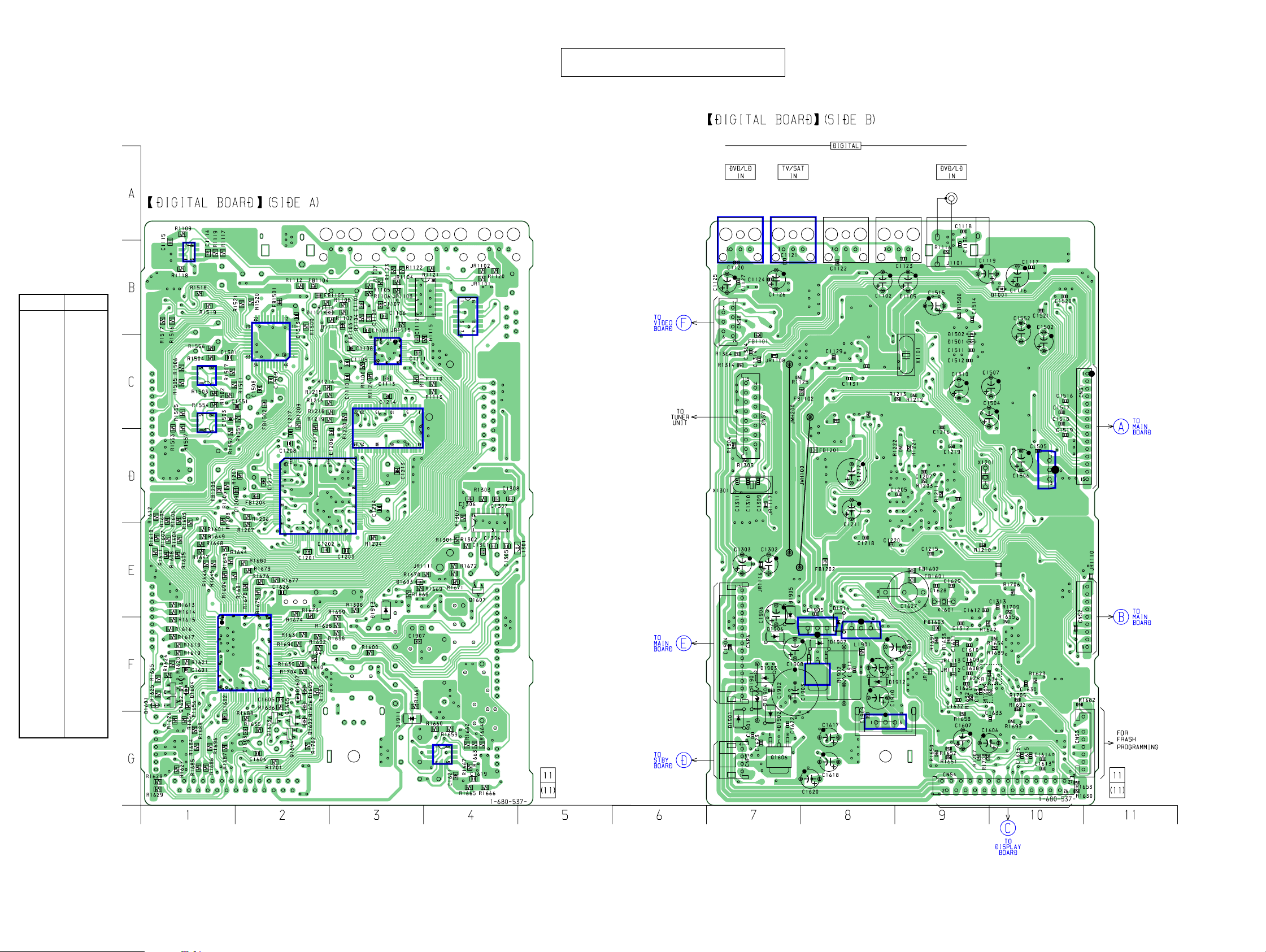
3-3. PRINTED WIRING BOARD – DIGITAL SECTION –
IC1102
• Semiconductor
Location
Ref. No. Location
D1001 B-10
D1101 B-2
D1501 C-9
D1502 C-9
D1601 F-1
D1602 G-2
D1901 G-7
D1902 G-7
D1903 F-7
D1904 F-7
D1911 G-3
D1912 F-8
D1913 E-3
D1914 E-8
IC1502
IC1552
IC1501
• See page 9 for Circuit Boards Location.
IC1103
IC1603
IC1101
IC1202
There are a few cases that the part printed on
this diagram isn’t mounted in this model.
IC1104
(Page 22)
IC1105
IC1106 IC1107
(Page 16)
IC1101 C-3
IC1102 B-1
IC1104 B-7
IC1105 B-8
IC1201 D-2
IC1202 C-3
IC1501 C-2
IC1502 C-1
IC1503 D-10
IC1552 C-1
IC1601 F-2
IC1603 B-4
IC1605 G-4
IC1901 F-8
IC1902 F-8
IC1903 G-8
IC1904 F-8
Q1601 F-1
Q1602 F-1
Q1603 G-2
Q1604 G-2
Q1605 G-2
Q1606 G-7
IC1601
IC1201
IC1605
IC1301
(Page 16)
(Page 24)
IC1901
IC1902
IC1904
IC1903
K502P : MY,SP,AUS
EXCEPT
AUS
IC1503
(Page 16)
(Page 20)
1212
Page 13
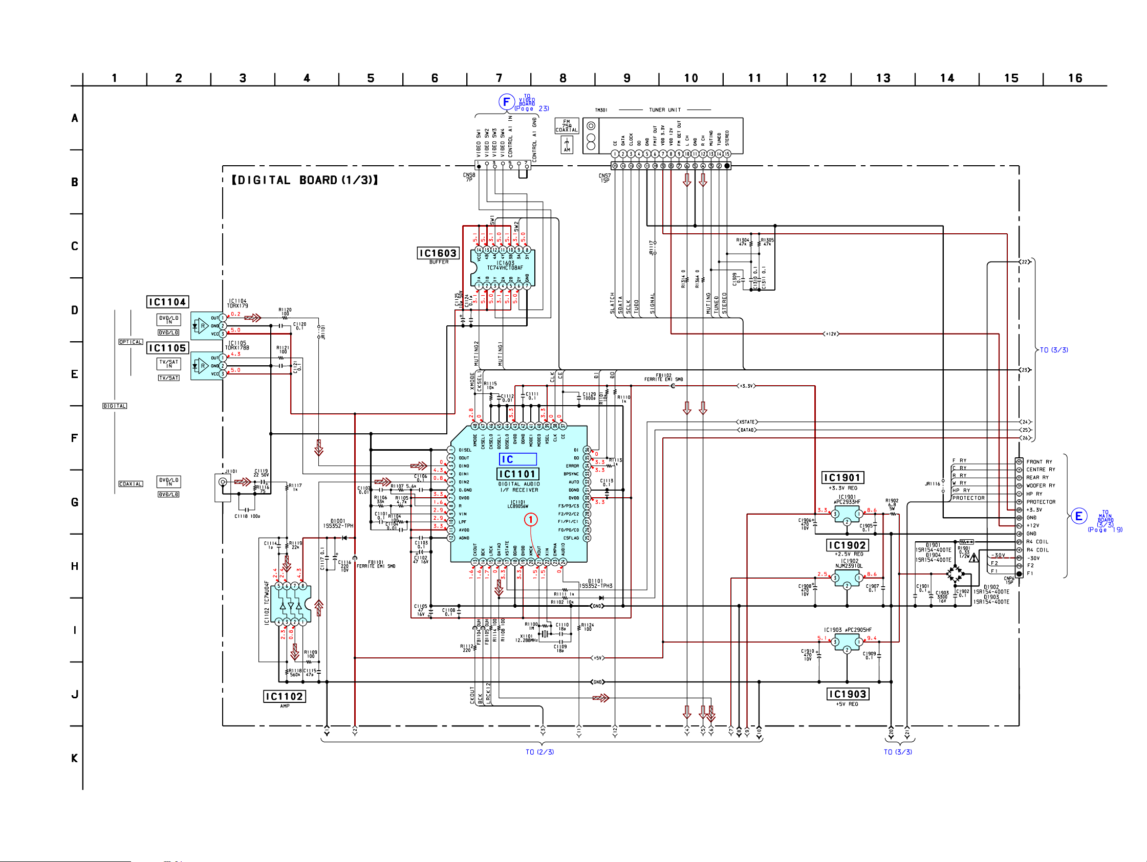
STR-DE575/K502/K502P
3-4. SCHEMATIC DIAGRAM – DIGITAL SECTION (1/3) –
• See page 9 for Waveform. • See page 25 for IC Block Diagrams.
B/D
1313
Page 14
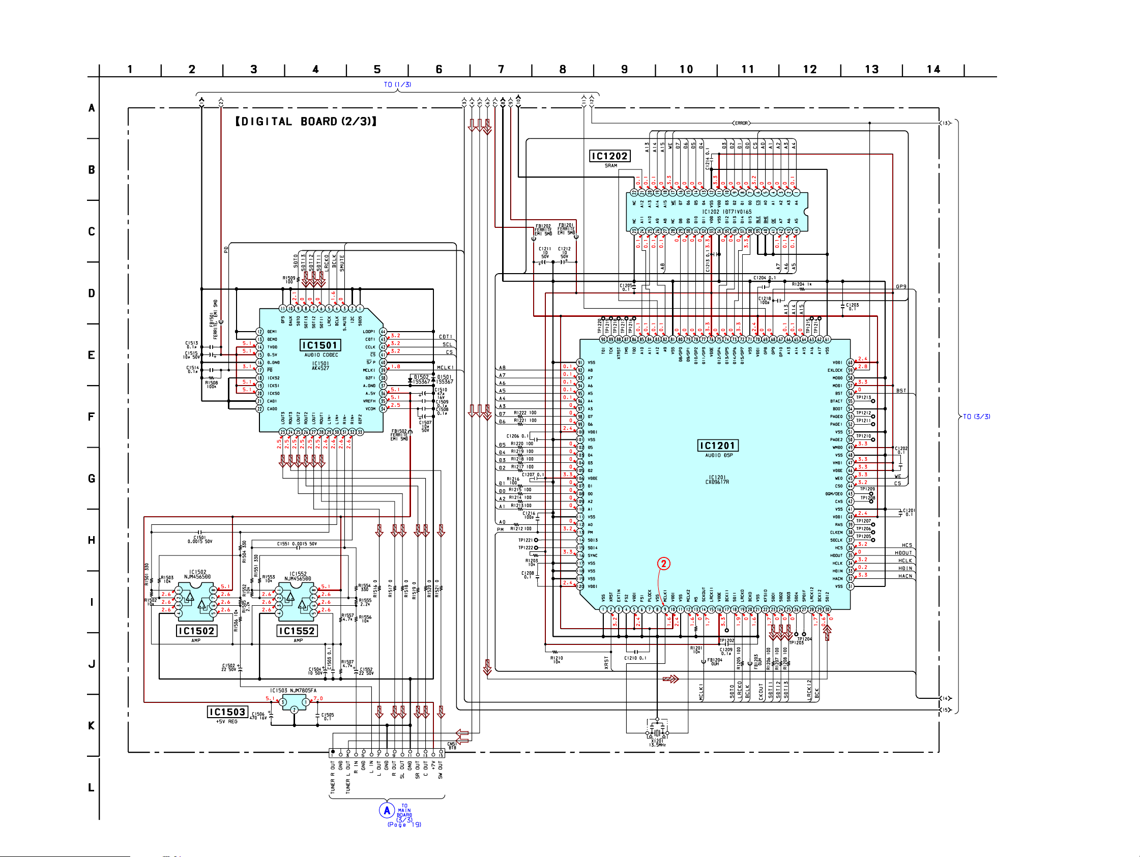
STR-DE575/K502/K502P
3-5. SCHEMATIC DIAGRAM – DIGITAL SECTION (2/3) –
• See page 9 for Waveform.
1414
Page 15

STR-DE575/K502/K502P
3-6. SCHEMATIC DIAGRAM – DIGITAL SECTION (3/3) –
• See page 9 for Waveform. • See page 25 for IC Block Diagrams.
• See page 27 for IC Pin Function.
3
B/D
1515
Page 16

STR-DE575/K502/K502P
3-7. PRINTED WIRING BOARD – MAIN SECTION –
EXCEPT K502P : MX
(Page 12)
• See page 9 for Circuit Boards Location.
EXCEPT K502P : MXK502P : MX
K502P : MX
IC201
IC801
IC802
There are a few cases that the part printed on
this diagram isn’t mounted in this model.
K502P : MX
EXCEPT K502P : MX
K502P : MX
IC807
IC804
(Page 12)
(Page 22)
(Page 12)
EXCEPT K502P : MX
• Semiconductor Location
Ref. No. Location
D505 F-2
D510 D-9
D540 F-4
D560 C-8
D605 F-11
D610 C-8
D640 F-7
D665 F-7
D680 F-10
D705 F-5
D710 D-10
D721 E-10
D722 E-10
D731 D-11
D732 E-11
D733 D-11
D734 D-11
D740 F-5
D750 F-9
D765 F-9
Ref. No. Location
D791 F-12
D801 F-13
D802 D-13
D804 F-12
D833 D-7
D896 D-5
IC201 D-4
IC401 E-3
IC501 F-2
IC601 E-8
IC701 E-6
IC702 E-7
IC801 C-5
IC802 D-5
IC803 E-11
IC804 D-6
IC806 E-12
IC807 C-7
IC401
IC501
Ref. No. Location Ref. No. Location
Q361 D-5
Q362 D-6
Q363 E-2
Q364 E-2
Q365 D-6
Q366 D-7
Q379 E-1
Q471 D-2
Q501 G-2
Q502 G-3
Q503 G-3
Q504 G-4
Q505 F-3
Q506 F-3
Q540 F-4
Q550 D-10
Q560 C-8
Q601 F-10
Q602 G-11
Q603 G-10
Q604 G-11
Q605 F-11
Q606 F-11
Q610 D-9
Q640 F-8
Q651 F-6
Q652 G-7
Q653 G-7
Q654 G-8
Q655 F-7
Q656 F-7
Q680 F-10
Q691 E-9
Q692 E-9
Q701 F-4
Q702 G-5
Q703 G-5
Q704 G-6
Q705 F-6
Q706 F-5
Ref. No. Location
Q710 D-10
Q722 E-11
Q723 E-11
Q725 E-10
Q740 F-5
Q747 E-5
Q748 E-5
Q750 F-9
Q751 F-8
Q752 G-9
Q753 G-9
Q754 G-9
Q755 F-9
Q756 F-9
Q790 E-13
Q801 F-13
IC701 IC702
EXCEPT
K502P : MX
EXCEPT K502P : MX
1616
IC601
EXCEPT K502P : MX
IC803
(Page 24)
IC806
(Page 24)
(Page 24)
Page 17

STR-DE575/K502/K502P
3-8. SCHEMATIC DIAGRAM – MAIN SECTION (1/3) –
• See page 26 for IC Block Diagrams.
B/D
B/D
B/D
1717
Page 18

STR-DE575/K502/K502P
3-9. SCHEMATIC DIAGRAM – MAIN SECTION (2/3) –
1.7uH
1.7uH
1.7uH
1.7uH
1.7uH
1818
Page 19

3-10. SCHEMATIC DIAGRAM – MAIN SECTION (3/3) –
STR-DE575/K502/K502P
1919
Page 20

STR-DE575/K502/K502P
3-11. PRINTED WIRING BOARD – DISPLAY SECTION –
TV/SAT
• See page 9 for Circuit Boards Location.
IC100
There are a few cases that the part printed on
this diagram isn’t mounted in this model.
IC102
(Page 12)
• Semiconductor
Location
Ref. No. Location
D100 C-6
D101 E-10
D102 B-9
D103 F-7
D104 F-6
D105 F-6
D106 E-9
D107 E-9
D108 E-8
D109 E-8
IC101
FM MODE
IC100 C-8
IC101 E-4
IC102 C-13
Q100 C-5
Q101 F-2
Q102 F-2
Q103 F-2
Q104 C-5
Q105 F-1
2020
Page 21

STR-DE575/K502/K502P
3-12. SCHEMATIC DIAGRAM – DISPLAY SECTION –
• See page 9 for Waveform. • See page 26 for IC Block Diagrams.
FM MODE
TV/SAT
B/D
2121
Page 22

STR-DE575/K502/K502P
3-13. PRINTED WIRING BOARD – VIDEO SECTION –
IC1801
• See page 9 for Circuit Boards Location.
IC1802
There are a few cases that the part printed on
this diagram isn’t mounted in this model.
IC103
(Page 16)
• Semiconductor
Location
Ref. No. Location
D203 E-8
D204 E-8
IC103 D-8
IC1802 B-2
(Page 12)
2222
Page 23

STR-DE575/K502/K502P
3-14. SCHEMATIC DIAGRAM – VIDEO SECTION –
• See page 26 for IC Block Diagrams.
B/D
B/D
2323
Page 24

STR-DE575/K502/K502P
3-15. PRINTED WIRING BOARD – POWER SECTION –
• See page 9 for Circuit Boards Location.
There are a few cases that the part printed on
this diagram isn’t mounted in this model.
(Page 16)
(Page 16)
(Page 16)
(Page 12)
2424
Page 25

3-16. IC BLOCK DIAGRAMS
IC1101 LC89056W-E (DIGITAL BOARD)
STR-DE575/K502/K502P
MODE0
MODE1
DOSEL0
DOSEL1
CKSEL0
CKSEL1
XMODE
DI
DO
AUTO
BPSYNC
ERROR
36
35
3334
31
37
CE
38
CL
MICROCOMPUTER
INTERFACE
39XSEL
40
MODE
SELECT
41
42DGND
43DVDD
44
45
46
47
SYSTEM
48
RESET
1 2 3 4
DISEL
DOUT
FREQUENCY
DEMODULATOR
DINO
SAMPLING
LOCK
DETECT
DATA
INPUT
CIRCUIT
DINI
DGND
5
30
DIN2
DVDD
F2/P2/C2
VF/P3/C3
C BIT
DETECT
TIMING
6
7
DGND
F0/P0/C0
F1/P1/C1
CLOCK
8 9 10
R
DVDD
252627282932
PLL
CSFLAG
PA/PB
DETECT
VIN
LPF
11
12
AVDD
AGND
AUDIO
24
23
EMPHA
22
XIN
21
XOUT
20
XMCK
19 DVDD
18 DGND
17
XSTATE
16
DATAO
LRCK
15
BCK
14
CKOUT
13
IC1605 NJM2103M-TE2 (DIGITAL BOARD)
CT
1
2
VSC
+
–
OUTC
3
GND
4
VREF
Q
R S
8
RESET
+
–
VSA
7
6
VSB/SESIN
V+
5
+
+
–
–
25
Page 26

STR-DE575/K502/K502P
IC501 STK350-230 (MAIN BOARD)
IC701 µPC2581V (MAIN BOARD)
IC702 µPC2581V (MAIN BOARD)
TR3 R1
TR4
TR7
R3
R8
R2
BIAS CIRCUIT
PROTECTOR
R6
TR6
D4 D3
R7
REG
1
MUTE
PRE
DRIVE
DRIVE
2
3 456 7 8 9 10 11 12 13 14 15
NF1
COMP1
+VOUT1
–VOUT1
IN1
GND
PRE
DRIVE
IN2
NF2
DRIVE
COMP2
–VOUT2
INPUT
-VEOUT
+VEOUT
GND
TR1
1
NF
2
3
4
5
6
7
SS
V
8
SUB
V
CC
9
D1 D2
TR2
R4
TR5
R5
R9
TR8
IC101 TC74VHC08AF(EL) (DISPLAY BOARD) IC1802 NJM2279D (S-VIDEO BOARD)
VCC1
+VOUT2
VCC2
VEE
1A
1
1B
2
3
1Y
4
2A
2B
5
6
2Y
GND
7
IC103 NJM2296D (VIDEO BOARD)
Vout2 Vout3
V+
S6
GND
Vin1 Vin2
S1
S4
VCC
14
4B
13
4A
12
11
4Y
10
3B
3A
9
3Y
8
SW2SW1
9
10111213141516
S7
S2
V-
SW213VIN112MUTE1
14
1
2
3
SW1
VIN3
VIN2
11
4
MUTE2
AMP
AMP
VOUT110NC9V+
5
GND26GND1
VOUT2
8
7
26
S5
1 52 3 4 6 7 8
Vout1
S3
SW5 SW4
SW3
V-
Vin3Vin4Vin5
Page 27

3-17. IC PIN FUNCTION DESCRIPTIONS
• IC1601 MB90478PF-G-101-BND (SYSTEM CONTROL)
STR-DE575/K502/K502P
Pin No.
1
2
3
4
5
6
7
8
9
10
11
12
13
14
15
16
17
18
19
20
21
22
23
24
25
26
27
28
29
30
31
32
33
34
35
36
37
38
39
40
41
42
43
44
45
46
47
48
49
50
Pin Name
DATAO
GP9
BST
HCS
HACN
XRST
PM
PD
SMUTE
CDT1
VSS
SCL
CS
DATA
CLK
LATCH
MUTING IN
HDOUT
HDIN
HCLK
F.MUTE
AC MUTING
VCC5
ANA/DIG
DCS LED
HP DETECT
FLASH2
SP SWITCH/FLASH1
EQ
MODE
2CH
AFD
—
—
AVCC
AVRH
AVSS
A/D0
A/D1
A/D2
A/D3
VSS
RDS SIGNAL
MODEL
VERSION
MULTI CH LED
STOP
GND (F)
MD0
MD1
I/O
I
Audio data signal input from DIR
I
GP9 signal input from DSP
O
BST signal output to DSP
O
HCS signal output to DSP
I
HACN signal input from DSP
O
Reset signal output to DSP
O
PM signal output to DSP
O
Power down signal output to AUDIO CODEC
O
Muting signal output to AUDIO CODEC
O
Control data signal output to AUDIO CODEC
—
Ground
O
Clock signal output to AUDIO CODEC
O
Chip select signal output to AUDIO CODEC
O
Control data signal output to the sound processor
O
Clock signal output to the sound processor
O
Latch signal output to the sound processor
O
Muting signal output to the sound processor
I
HDOUT signal input from DSP
O
HDIN signal output to DSP
O
Clock signal output to DSP
O
Muting signal output
O
Muting signal output to the power amplifier
—
Power supply
I
Muting and error signal input
O
DCS LED control signal output
I
Headphone switch detect signal input
O
Terminal for FLASH programming
I/O
Speaker ON/OFF switch signal input / Terminal for FLASH programming
O
EQ LED control signal output
O
MODE LED control signal output
O
2CH LED control signal output
O
AFD LED control signal output
I
Not used
I
Not used
—
Analog power supply
—
Analog reference voltage input
—
Analog ground
I
Function key push signal input
I
Function key push signal input
I
Function key push signal input
I
Function key push signal input
—
Ground
I
RDS signal detect input
I
Version setting input (MODEL)
I
Version setting input (DESTINATION)
O
MULTI CH LED control signal output
I
AC off detect signal input
I
Terminal for FLASH programming (Ground)
—
Operation mode setting input
—
Operation mode setting input
Description
27
Page 28

STR-DE575/K502/K502P
Pin No.
51
52
53
54
55
56
57
58
59
60
61
62
63
64
65
66
67
68
69
70
71
72
73
74
75
76
77
78
79
80
81
82
83
84
85
86
87
88
89
90
91
92
93
94
95
96
97
98
99
100
Pin Name
MD2
RDS CLOCK
RDS DATA
SIRCS
SLEEP
POWER KEY
JOGJOG+
VOL-
VOL+
DIN
CLK
STB
CONTROL A1 OUT
CONTROL A1 IN
POWER RELAY
PROTECTOR
HEADPHONE RELAY
WOOFER RELAY
REAR RELAY
CENTRE RELAY
FRONT RELAY
STEREO
TUNED
MUTING
DO
RSTX
SCLK
X1A
X0A
VSS
X0
X1
VCC3
—
SDATA
SLATCH
S1
S2
MUTING1
MUTING2
OPTICAL IN SELECT
XMODE
CKSEL 1
CLK
CE
DI
DO
ERROR
XSTATE
I/O
—
Operation mode setting input
I
RDS clock signal input (Not used)
I
RDS data signal input (Not used)
I
Data signal input from the remote control sensor
I
Not used
I
Power switch key detect signal input
I
Jog dial signal input from the rotary encoder
I
Jog dial signal input from the rotary encoder
I
Volume signal input from the rotary encoder
I
Volume signal input from the rotary encoder
O
Data signal output to the FL tube driver
O
Clock signal output to the FL tube driver
O
Strobe signal output to the FL tube driver
O
Control A1 signal output
I
Control A1 signal input
O
Power relay control signal output
I
Protector status detect signal input
O
Headphone relay control signal output
O
Woofer relay control signal output
O
Rear speaker relay control signal output
O
Centre speaker relay control signal output
O
Front speaker relay control signal output
I
Stereo tuning signal input from the tuner
I
Tuning a frequency signal input from the tuner
O
Muting signal output to the tuner
I
Frequency data signal input from the tuner
—
System reset
O
Clock signal output to the tuner
—
Not used
—
Not used
—
Ground
—
Connection for a crystal resonator
—
Connection for a crystal resonator
—
Power supply
—
Not used
O
Data signal output to the tuner
O
Latch signal output to the tuner
O
Video select control signal output
O
Video select control signal output
O
Video muting control signal output
O
Video muting control signal output
O
Optical in selector control signal output (Not used)
O
Reset signal output to DIR
O
CKSEL control signal to DIR
O
Clock signal output to DIR
O
Chip enable signal output to DIR
O
Data signal output to DIR
I
Data signal input from DIR
I
PLL error muting signal input from DIR
I
XSTATE data signal input from DIR
Description
28
Page 29

NOTE:
2
3
4
1
5
5
5
5
6
9
10
11
12
12
13
12
8
8
#1
#1
Supplied with
RV101
Supplied with
RV102
7
FL101
chassis section
• -XX, -X mean standardized parts, so they may
have some differences from the original one.
• Items marked “*” are not stocked since they
are seldom required for routine service. Some
delay should be anticipated when ordering these
items.
Color Indication of Appearance Parts Example:
•
KNOB, BALANCE (WHITE) . . . (RED)
Parts of Color Cabinet’s Color
↑ ↑
4-1. FRONT PANEL SECTION
SECTION 4
EXPLODED VIEWS
• The mechanical parts with no reference number
in the exploded views are not supplied.
• Accessories and packing materials are given in
the last of this parts list.
• Abbreviation
CND : Canadian model
MY : Malaysia model
SP : Singapore model
MX : Mexican model
AUS : Australian model
STR-DE575/K502/K502P
The components identified by mark 0 or
dotted line with mark 0 are critical for safety.
Replace only with part number specified.
Les composants identifiés par une marque
0 sont critiques pour la sécurité.
Ne les remplacer que par une pièce portant
le numéro spécifié.
Ref. No. Part No. Description Remarks Ref. No. Part No. Description Remarks
1 X-4953-461-1 FRONT PANEL ASSY (BLACK) (DE575:US)
1 X-4953-524-1 FRONT PANEL ASSY (BLACK) (DE575:CND)
1 X-4953-660-1 FRONT PANEL ASSY (BLACK) (K502P:US,CND)
1 X-4953-661-1 FRONT PANEL ASSY (SILVER)
1 X-4953-896-1 FRONT PANEL ASSY (BLACK) (K502)
(K502P:US,CND,MY,SP,MX,AUS)
2 4-232-113-01 KNOB (VOL) (BLACK)
2 4-232-113-11 KNOB (VOL) (SILVER)
3 4-232-239-01 KNOB (JOG) (BLACK)
3 4-232-239-21 KNOB (JOG) (SILVER)
4 1-680-529-11 HEADPHONE BOARD
5 4-951-620-01 SCREW (2.6X8), +BVTP
6 1-680-532-11 JOG BOARD
7 1-773-250-11 WIRE (FLAT TYPE) (27 CORE)
* 8 4-921-941-01 CUSHION (FL)
(DE575/K502/K502P:US,CND)
(K502P:US,CND,MY,SP,MX,AUS)
(DE575/K502/K502P:US,CND)
(K502P:US,CND,MY,SP,MX,AUS)
* 9 3-386-245-11 HOLDER (FL)
10 A-4475-897-A DISPLAY BOARD,COMPLETE
10 A-4475-905-A DISPLAY BOARD,COMPLETE (DE575:CND)
10 A-4476-963-A DISPLAY BOARD,COMPLETE
10 A-4476-967-A DISPLAY BOARD,COMPLETE (K502P:CND)
10 A-4476-970-A DISPLAY BOARD,COMPLETE (K502P:MX)
11 1-680-528-11 POWER SWITCH BOARD
12 4-210-291-01 SCREW (CASE 3 TP2) (FOR BLACK)
12 4-210-291-11 SCREW (CASE 3 TP2) (FOR SILVER)
13 4-232-418-01 CASE (BLACK)(DE575/K502/K502P:US,CND)
13 4-232-418-21 CASE (SILVER)(K502P:US,CND,MY,SP,MX,AUS)
FL101 1-518-718-11 INDICATOR TUBE, FLUORESCENT
#1 7-685-646-79 SCREW +BVTP 3X8 TYPE2 IT-3
(DE575:US/K502/K502P:US)
(DE575/K502/K502P:US,CND)
(K502P:US,CND,MY,SP,MX,AUS)
(K502P:MY,SP,AUS)
29
Page 30

STR-DE575/K502/K502P
4-2. CHASSIS SECTION
#2
not supplied
#1
not supplied
#2
#1
63
#1
65
68
#1 #1
#1
#1
#1
#1
#1
#1
T901
52
#3
#3
70
#2
not supplied
53
#1
#1
#1
54
51
not supplied
69
51
#1
61
55
#1
56
#1
#1
#1
not supplied
62
#1
60
66
59
57
58
not supplied
69
30
Page 31

STR-DE575/K502/K502P
Ver 1.1 2002.07
Ref. No. Part No. Description Remarks Ref. No. Part No. Description Remarks
51 4-232-237-01 FOOT (DIA. 30)
52 4-233-263-01 SUB MOLD (DE9)
53 A-4475-895-A MAIN BOARD,COMPLETE
(DE575:US/K502/K502P:US)
53 A-4475-904-A MAIN BOARD,COMPLETE
(DE575:CND/K502P:CND)
53 A-4476-957-A MAIN BOARD,COMPLETE (K502P:MY,SP,AUS)
53 A-4476-968-A MAIN BOARD,COMPLETE (K502P:MX)
54 3-905-609-01 SCREW (TRANSISTOR)
55 1-769-844-11 WIRE (FLAT TYPE) (5 CORE)
56 1-680-538-11 S-VIDEO BOARD
57 1-765-314-11 WIRE (FLAT TYPE) (7 CORE)
58 A-4475-900-A DIGITAL BOARD,COMPLETE
(DE575:US/K502/K502P:US,MX)
58 A-4475-908-A DIGITAL BOARD,COMPLETE
(DE575:CND/K502P:CND)
58 A-4476-965-A DIGITAL BOARD,COMPLETE (K502P:AUS)
58 A-4476-959-A DIGITAL BOARD,COMPLETE (K502P:MY,SP)
59 1-693-540-11 TUNER UNIT (K502/K502P)
59 1-693-539-11 TUNER UNIT(DE575)
60 1-773-004-11 WIRE (FLAT TYPE) (15 CORE)
61 1-769-905-11 WIRE (FLAT TYPE) (9 CORE)
62 1-680-533-11 VIDEO BOARD
63 A-4475-896-A STBY BOARD,COMPLETE
(DE575/K502/K502P:US,CND)
63 A-4476-958-A STBY BOARD,COMPLETE (K502P:MY,SP)
63 A-4476-964-A STBY BOARD,COMPLETE (K502P:AUS)
63 A-4476-969-A STBY BOARD,COMPLETE (K502P:MX)
* 65 3-703-244-00 BUSHING (2104), CORD
66 4-232-240-01 BACK PANEL (DE5) (DE575:US)
66 4-232-240-11 BACK PANEL (DE5) (DE575:CND)
66 4-232-240-31 BACK PANEL (DE5) (K502P:US)
66 4-232-240-41 BACK PANEL (DE5) (K502P:CND)
66 4-232-240-51 BACK PANEL (DE5) (K502P:AUS)
66 4-232-240-61 BACK PANEL (DE5) (K502P:MY,SP)
66 4-232-240-71 BACK PANEL (DE5) (K502P:MX)
66 4-232-240-81 BACK PANEL (DE5) (K502)
068 1-783-820-11 CORD, POWER
69 X-4953-448-1 FOOT ASSY
70 3-701-748-00 CLAMP
0T901 1-435-902-11 POWER TRANSFORMER (AUS)
0T901 1-435-903-11 POWER TRANSFORMER (MY,SP)
0T901 1-435-905-11 POWER TRANSFORMER
0T901 1-435-906-11 POWER TRANSFORMER
#1 7-685-646-79 SCREW +BVTP 3X8 TYPE2 IT-3
#2 7-685-645-79 SCREW +BVTP 3X6 TYPE2 N-S
#3 7-685-880-09 SCREW +BVTT 4X6 (S)
The components identified by
mark 0 or dotted line with mark
0 are critical for safety.
Replace only with part number
specified.
(DE575:CND/K502P:CND)
(DE575:US/K502/K502P:US,MX)
Les composants identifiés par
une marque 0 sont critiques
pour la sécurité.
Ne les remplacer que par une
pièce portant le numéro spécifié.
31
Page 32

STR-DE575/K502/K502P
SECTION 5
DIGITAL
NOTE:
• Due to standardization, replacements in the
parts list may be different from the parts
specified in the diagrams or the components
used on the set.
• -XX, -X mean standardized parts, so they
may have some difference from the original
one.
• Items marked “*” are not stocked since they
are seldom required for routine service.
Some delay should be anticipated when
ordering these items.
• RESISTORS
All resistors are in ohms.
METAL: metal-film resistor
MET AL O XIDE: Metal Oxide-film r esistor
F: nonflammable
Ref. No. Part No. Description Remarks Ref. No. Part No. Description Remarks
A-4475-900-A DIGITAL BOARD, COMPLETE
***********************
A-4475-908-A DIGITAL BOARD, COMPLETE
***********************
A-4476-959-A DIGITAL BOARD, COMPLETE (K502P:MY,SP)
***********************
A-4476-965-A DIGITAL BOARD, COMPLETE (K502P:AUS)
***********************
< CAPACITOR >
C1101 1-163-038-11 CERAMIC CHIP 0.1uF 25V
C1102 1-104-664-11 ELECT 47uF 20.00% 16V
C1103 1-163-038-11 CERAMIC CHIP 0.1uF 25V
C1104 1-162-974-11 CERAMIC CHIP 0.01uF 50V
C1105 1-104-664-11 ELECT 47uF 20.00% 16V
C1106 1-163-038-11 CERAMIC CHIP 0.1uF 25V
C1107 1-162-974-11 CERAMIC CHIP 0.01uF 50V
C1108 1-163-038-11 CERAMIC CHIP 0.1uF 25V
C1109 1-162-918-11 CERAMIC CHIP 18PF 5.00% 50V
C1110 1-162-918-11 CERAMIC CHIP 18PF 5.00% 50V
C1111 1-163-038-11 CERAMIC CHIP 0.1uF 25V
C1112 1-162-974-11 CERAMIC CHIP 0.01uF 50V
C1113 1-163-038-11 CERAMIC CHIP 0.1uF 25V
C1114 1-162-905-11 CERAMIC CHIP 1PF 0.25PF 50V
C1115 1-162-923-11 CERAMIC CHIP 47PF 5% 50V
C1116 1-126-934-11 ELECT 220uF 20.00% 10V
C1117 1-164-156-11 CERAMIC CHIP 0.1uF 25V
C1118 1-162-927-11 CERAMIC CHIP 100PF 5% 50V
C1119 1-126-965-11 ELECT 22uF 20.00% 50V
C1120 1-164-156-11 CERAMIC CHIP 0.1uF 25V
C1121 1-164-156-11 CERAMIC CHIP 0.1uF 25V
C1124 1-164-156-11 CERAMIC CHIP 0.1uF 25V
C1125 1-126-964-11 ELECT 10uF 20.00% 50V
C1129 1-162-964-11 CERAMIC CHIP 0.001uF 10% 50V
C1201 1-163-038-11 CERAMIC CHIP 0.1uF 25V
C1202 1-163-038-11 CERAMIC CHIP 0.1uF 25V
C1203 1-163-038-11 CERAMIC CHIP 0.1uF 25V
C1204 1-163-038-11 CERAMIC CHIP 0.1uF 25V
C1205 1-164-156-11 CERAMIC CHIP 0.1uF 25V
C1206 1-164-156-11 CERAMIC CHIP 0.1uF 25V
C1207 1-164-156-11 CERAMIC CHIP 0.1uF 25V
C1208 1-163-038-11 CERAMIC CHIP 0.1uF 25V
C1209 1-163-038-11 CERAMIC CHIP 0.1uF 25V
C1210 1-163-038-11 CERAMIC CHIP 0.1uF 25V
C1211 1-126-964-11 ELECT 10uF 20.00% 50V
ELECTRICAL PARTS LIST
• COILS
uH: µH
• CAPACITORS:
uF: µF
• SEMICONDUCTORS
In each case, u: µ, for example:
uA...: µA... , uPA... , µPA... ,
uPB... , µPB... , uPC... , µPC... ,
uPD..., µPD...
• Abbreviation
CND : Canadian model
MY : Malaysia model
SP : Singapore model
MX : Mexican model
AUS : Australian model
(DE575:US/K502/K502P:US,MX)
(DE575:CND/K502P:CND)
When indicating parts by reference number,
please include the board name.
The components identified by mark 0 or
dotted line with mark 0 are critical for safety.
Replace only with part number specified.
Les composants identifiés par une marque
0 sont critiques pour la sécurité.
Ne les remplacer que par une pièce portant
le numéro spécifié.
C1212 1-126-964-11 ELECT 10uF 20.00% 50V
C1213 1-163-038-11 CERAMIC CHIP 0.1uF 25V
C1214 1-163-038-11 CERAMIC CHIP 0.1uF 25V
C1216 1-162-927-11 CERAMIC CHIP 100PF 5% 50V
C1218 1-162-927-11 CERAMIC CHIP 100PF 5% 50V
C1309 1-164-156-11 CERAMIC CHIP 0.1uF 25V
C1310 1-164-156-11 CERAMIC CHIP 0.1uF 25V
C1311 1-164-156-11 CERAMIC CHIP 0.1uF 25V
C1312 1-163-259-11 CERAMIC CHIP 220PF 5.00% 50V
C1313 1-163-259-11 CERAMIC CHIP 220PF 5.00% 50V
C1501 1-162-965-11 CERAMIC CHIP 0.0015uF 10% 50V
C1502 1-126-965-11 ELECT 22uF 20.00% 50V
C1503 1-163-038-11 CERAMIC CHIP 0.1uF 25V
C1504 1-126-964-11 ELECT 10uF 20.00% 50V
C1505 1-164-156-11 CERAMIC CHIP 0.1uF 25V
C1506 1-126-935-11 ELECT 470uF 20.00% 16V
C1507 1-126-964-11 ELECT 10uF 20.00% 50V
C1508 1-163-038-11 CERAMIC CHIP 0.1uF 25V
C1509 1-163-038-11 CERAMIC CHIP 0.1uF 25V
C1510 1-104-664-11 ELECT 47uF 20.00% 16V
C1513 1-163-038-11 CERAMIC CHIP 0.1uF 25V
C1514 1-164-156-11 CERAMIC CHIP 0.1uF 25V
C1515 1-126-964-11 ELECT 10uF 20.00% 50V
C1551 1-162-965-11 CERAMIC CHIP 0.0015uF 10% 50V
C1552 1-126-965-11 ELECT 22uF 20.00% 50V
C1601 1-163-038-11 CERAMIC CHIP 0.1uF 25V
C1602 1-163-038-11 CERAMIC CHIP 0.1uF 25V
C1603 1-163-038-11 CERAMIC CHIP 0.1uF 25V
C1604 1-163-038-11 CERAMIC CHIP 0.1uF 25V
C1605 1-163-038-11 CERAMIC CHIP 0.1uF 25V
C1606 1-104-664-11 ELECT 47uF 20.00% 16V
C1607 1-126-963-11 ELECT 4.7uF 20.00% 50V
C1608 1-162-974-11 CERAMIC CHIP 0.01uF 50V
C1609 1-162-974-11 CERAMIC CHIP 0.01uF 50V
C1610 1-162-974-11 CERAMIC CHIP 0.01uF 50V
C1611 1-162-974-11 CERAMIC CHIP 0.01uF 50V
C1612 1-164-156-11 CERAMIC CHIP 0.1uF 25V
C1613 1-162-995-11 CERAMIC CHIP 0.022uF 50V
C1614 1-162-995-11 CERAMIC CHIP 0.022uF 50V
C1615 1-162-995-11 CERAMIC CHIP 0.022uF 50V
C1616 1-162-995-11 CERAMIC CHIP 0.022uF 50V
C1617 1-126-957-11 ELECT 0.22uF 20.00% 50V
C1618 1-126-964-11 ELECT 10uF 20.00% 50V
C1619 1-163-038-11 CERAMIC CHIP 0.1uF 25V
C1620 1-126-960-11 ELECT 1uF 20.00% 50V
32
Page 33

STR-DE575/K502/K502P
DIGITAL
Ref. No. Part No. Description Remarks Ref. No. Part No. Description Remarks
C1621 1-163-038-11 CERAMIC CHIP 0.1uF 25V
C1622 1-164-156-11 CERAMIC CHIP 0.1uF 25V
C1623 1-164-156-11 CERAMIC CHIP 0.1uF 25V
C1626 1-163-038-11 CERAMIC CHIP 0.1uF 25V
C1627 1-104-905-11 CAPACITOR 0.22F 5.5V
FB1601 1-414-813-11 FERRITE 0UH
FB1602 1-414-813-11 FERRITE 0UH
FB1603 1-414-813-11 FERRITE 0UH
< IC >
C1628 1-162-908-11 CERAMIC CHIP 3PF 0.25PF 50V
C1629 1-162-908-11 CERAMIC CHIP 3PF 0.25PF 50V
C1901 1-164-156-11 CERAMIC CHIP 0.1uF 25V
C1902 1-164-156-11 CERAMIC CHIP 0.1uF 25V
C1903 1-126-936-11 ELECT 3300uF 20.00% 16V
C1905 1-164-156-11 CERAMIC CHIP 0.1uF 25V
C1906 1-126-935-11 ELECT 470uF 20.00% 10V
C1907 1-163-038-11 CERAMIC CHIP 0.1uF 25V
C1908 1-126-935-11 ELECT 470uF 20.00% 10V
C1909 1-164-156-11 CERAMIC CHIP 0.1uF 25V
C1910 1-126-935-11 ELECT 470uF 20.00% 10V
C1911 1-164-156-11 CERAMIC CHIP 0.1uF 25V
C1912 1-126-935-11 ELECT 470uF 20.00% 10V
C1913 1-126-964-11 ELECT 10uF 20.00% 50V
< CONNECTOR >
* CNP5 1-564-720-11 PIN, CONNECTOR (SMALL TYPE) 4P
* CNP6 1-564-731-11 PIN, CONNECTOR (SMALL TYPE)15P
* CNS1 1-573-829-11 CONNECTOR, BOARD TO BOARD 15P
CNS2 1-784-041-11 CONNECTOR, BOARD TO BOARD 9P
* CNS3 1-564-710-11 PIN, CONNECTOR (SMALL TYPE) 8P
CNS4 1-569-327-11 SOCKET, CONNECTOR 27P
CNS7 1-569-321-11 SOCKET, CONNECTOR 15P
CNS8 1-568-439-11 SOCKET, CONNECTOR 7P
< DIODE >
IC1101 8-759-825-15 IC LC89056W-E
IC1102 8-759-242-70 IC TC7WU04F(TE12R)
IC1104 8-749-017-36 IC TORX-179 (DVD/LD IN)
IC1105 8-749-923-05 TORX178B (TV/SAT IN)
IC1201 8-759-698-76 IC CXD9617R
IC1202 8-759-538-16 IC IDT71V016S15PH-AUTL
IC1501 8-759-657-47 IC AK4527
IC1502 8-759-636-74 IC NJM4565DD
IC1503 8-759-701-75 IC NJM7805FA
IC1552 8-759-636-74 IC NJM4565DD
IC1601 8-759-832-67 IC MB90478PF-G-101-BND
IC1603 8-759-491-33 IC TC74VHCT08AF(EL)
IC1605 8-759-544-04 IC NJM2103M-TE2
IC1901 8-759-647-10 IC uPC2933HF
IC1902 8-759-835-63 IC NJM2391DL1-26-TE1
IC1903 8-759-647-11 IC uPC2905HF
IC1904 8-759-647-10 IC uPC2933HF
< JACK >
J1101 1-778-228-11 JACK, PIN 1P (DVD/LD IN)
< JUMPER RESISTOR >
JR1101 1-216-295-11 SHORT 0
JR1111 1-216-295-11 SHORT 0
JR1116 1-216-295-11 SHORT 0
D1001 8-719-016-74 DIODE 1SS352-TPH3
D1101 8-719-016-74 DIODE 1SS352-TPH3
D1501 8-719-049-09 DIODE 1SS367-T3SONY
D1502 8-719-049-09 DIODE 1SS367-T3SONY
D1601 8-719-016-74 DIODE 1SS352-TPH3
D1602 8-719-016-74 DIODE 1SS352-TPH3
D1901 8-719-053-18 DIODE 1SR154-400TE-25
D1902 8-719-053-18 DIODE 1SR154-400TE-25
D1903 8-719-053-18 DIODE 1SR154-400TE-25
D1904 8-719-053-18 DIODE 1SR154-400TE-25
D1911 8-719-053-18 DIODE 1SR154-400TE-25
D1912 8-719-053-18 DIODE 1SR154-400TE-25
D1913 8-719-053-18 DIODE 1SR154-400TE-25
D1914 8-719-053-18 DIODE 1SR154-400TE-25
< FERRITE BEAD >
FB1101 1-414-813-11 FERRITE 0UH
FB1102 1-414-813-11 FERRITE 0UH
FB1104 1-469-152-11 FERRITE 0UH
FB1105 1-469-152-11 FERRITE 0UH
FB1201 1-414-813-11 FERRITE 0UH
FB1202 1-414-813-11 FERRITE 0UH
FB1203 1-469-152-11 FERRITE 0UH
FB1204 1-469-152-11 FERRITE 0UH
FB1501 1-414-813-11 FERRITE 0UH
FB1502 1-414-813-11 FERRITE 0UH
< JUMPER >
JWH200 1-164-124-11 CERAMIC 300PF 5.00% 50V
< COIL >
L1901 1-216-295-11 SHORT 0
< TRANSISTOR >
Q1601 8-729-027-43 TRANSISTOR RT1N141C-TP-1
Q1602 8-729-230-49 TRANSISTOR 2SC2712-YG-TE85L
Q1603 8-729-230-49 TRANSISTOR 2SC2712-YG-TE85L
Q1604 8-729-027-43 TRANSISTOR RT1N141C-TP-1
Q1605 8-729-113-69 TRANSISTOR FN1F4M-T1M32
Q1606 8-729-048-78 TRANSISTOR 2SD1733-TL-QR
< RESISTOR >
R1100 1-216-121-11 RES-CHIP 1M 5% 1/10W
R1101 1-216-073-00 METAL CHIP 10K 5% 1/10W
R1102 1-216-073-00 METAL CHIP 10K 5% 1/10W
R1104 1-216-025-11 RES-CHIP 100 5% 1/10W
R1105 1-216-065-11 RES-CHIP 4.7K 5% 1/10W
R1106 1-216-085-00 METAL CHIP 33K 5% 1/10W
R1107 1-216-067-00 METAL CHIP 5.6K 5% 1/10W
R1108 1-216-025-11 RES-CHIP 100 5% 1/10W
R1109 1-216-025-11 RES-CHIP 100 5% 1/10W
R1110 1-216-049-11 RES-CHIP 1K 5% 1/10W
33
Page 34

STR-DE575/K502/K502P
DIGITAL
Ref. No. Part No. Description Remarks Ref. No. Part No. Description Remarks
R1111 1-216-049-11 RES-CHIP 1K 5% 1/10W
R1112 1-216-033-00 METAL CHIP 220 5% 1/10W
R1113 1-216-049-11 RES-CHIP 1K 5% 1/10W
R1114 1-216-025-11 RES-CHIP 100 5% 1/10W
R1115 1-216-073-00 METAL CHIP 10K 5% 1/10W
R1602 1-216-065-11 RES-CHIP 4.7K 5% 1/10W
R1603 1-216-049-11 RES-CHIP 1K 5% 1/10W
R1604 1-216-809-91 RES-CHIP 100 5% 1/16W
R1605 1-216-809-91 RES-CHIP 100 5% 1/16W
R1606 1-216-049-11 RES-CHIP 1K 5% 1/10W
R1116 1-216-022-00 METAL CHIP 75 5% 1/10W
R1117 1-216-049-11 RES-CHIP 1K 5% 1/10W
R1118 1-216-115-00 METAL CHIP 560K 5% 1/10W
R1119 1-216-081-00 METAL CHIP 22K 5% 1/10W
R1120 1-216-025-11 RES-CHIP 100 5% 1/10W
R1121 1-216-025-11 RES-CHIP 100 5% 1/10W
R1124 1-216-025-11 RES-CHIP 100 5% 1/10W
R1201 1-216-073-00 METAL CHIP 10K 5% 1/10W
R1203 1-216-073-00 METAL CHIP 10K 5% 1/10W
R1204 1-216-049-11 RES-CHIP 1K 5% 1/10W
R1205 1-216-025-11 RES-CHIP 100 5% 1/10W
R1206 1-216-025-11 RES-CHIP 100 5% 1/10W
R1207 1-216-025-11 RES-CHIP 100 5% 1/10W
R1208 1-216-025-11 RES-CHIP 100 5% 1/10W
R1210 1-216-073-00 METAL CHIP 10K 5% 1/10W
R1212 1-216-809-91 RES-CHIP 100 1/16W
R1213 1-216-809-91 RES-CHIP 100 1/16W
R1214 1-216-809-91 RES-CHIP 100 1/16W
R1215 1-216-809-91 RES-CHIP 100 1/16W
R1216 1-216-809-91 RES-CHIP 100 1/16W
R1217 1-216-809-91 RES-CHIP 100 1/16W
R1218 1-216-809-91 RES-CHIP 100 1/16W
R1219 1-216-809-91 RES-CHIP 100 1/16W
R1220 1-216-809-91 RES-CHIP 100 1/16W
R1221 1-216-809-91 RES-CHIP 100 1/16W
R1222 1-216-809-91 RES-CHIP 100 1/16W
R1304 1-216-089-11 RES-CHIP 47K 5% 1/10W
R1305 1-216-089-11 RES-CHIP 47K 5% 1/10W
R1308 1-216-049-11 RES-CHIP 1K 5% 1/10W
R1314 1-216-295-11 SHORT 0
R1364 1-216-295-11 SHORT 0
R1501 1-216-037-00 METAL CHIP 330 5% 1/10W
R1502 1-216-073-00 METAL CHIP 10K 5% 1/10W
R1503 1-216-073-00 METAL CHIP 10K 5% 1/10W
R1504 1-216-037-00 METAL CHIP 330 5% 1/10W
R1607 1-216-049-11 RES-CHIP 1K 5% 1/10W
R1608 1-216-049-11 RES-CHIP 1K 5% 1/10W
R1609 1-216-049-11 RES-CHIP 1K 5% 1/10W
R1610 1-216-049-11 RES-CHIP 1K 5% 1/10W
R1611 1-216-049-11 RES-CHIP 1K 5% 1/10W
R1612 1-216-049-11 RES-CHIP 1K 5% 1/10W
R1613 1-216-049-11 RES-CHIP 1K 5% 1/10W
R1614 1-216-049-11 RES-CHIP 1K 5% 1/10W
R1615 1-216-049-11 RES-CHIP 1K 5% 1/10W
R1616 1-216-049-11 RES-CHIP 1K 5% 1/10W
R1617 1-216-809-91 RES-CHIP 100 5% 1/16W
R1618 1-216-809-91 RES-CHIP 100 5% 1/16W
R1619 1-216-809-91 RES-CHIP 100 5% 1/16W
R1620 1-216-049-11 RES-CHIP 1K 5% 1/10W
R1621 1-216-049-11 RES-CHIP 1K 5% 1/10W
R1623 1-216-073-00 METAL CHIP 10K 5% 1/10W
R1624 1-216-073-00 METAL CHIP 10K 5% 1/10W
R1625 1-216-073-00 METAL CHIP 10K 5% 1/10W
R1626 1-216-073-00 METAL CHIP 10K 5% 1/10W
R1627 1-216-073-00 METAL CHIP 10K 5% 1/10W
R1628 1-216-073-00 METAL CHIP 10K 5% 1/10W
R1629 1-216-073-00 METAL CHIP 10K 5% 1/10W
R1630 1-216-073-00 METAL CHIP 10K 5% 1/10W
R1631 1-216-065-91 RES-CHIP 4.7K 5% 1/10W
R1632 1-216-057-00 METAL CHIP 2.2K 5% 1/10W
(DE575/K502/K502P:US,CND,MX)
R1632 1-216-045-00 METAL CHIP 680 5% 1/10W
(K502P:MY,SP,AUS)
R1633 1-216-081-00 METAL CHIP 22K 5% 1/10W
(DE575/K502/K502P:US,CND,MX)
R1633 1-216-077-11 RES-CHIP 15K 5% 1/10W
(K502P:MY,SP,AUS)
R1634 1-216-085-00 METAL CHIP 33K 5% 1/10W
(K502P:AUS)
R1634 1-216-081-00 METAL CHIP 22K 5% 1/10W
(K502P:MY,SP)
R1505 1-216-057-00 METAL CHIP 2.2K 5% 1/10W
R1506 1-216-073-00 METAL CHIP 10K 5% 1/10W
R1507 1-216-065-91 RES-CHIP 4.7K 5% 1/10W
R1508 1-216-097-11 RES-CHIP 100K 5% 1/10W
R1509 1-216-025-11 RES-CHIP 100 5% 1/10W
R1516 1-216-295-11 SHORT 0
R1517 1-216-295-11 SHORT 0
R1518 1-216-295-11 SHORT 0
R1519 1-216-295-11 SHORT 0
R1520 1-216-295-11 SHORT 0
R1521 1-216-295-11 SHORT 0
R1551 1-216-037-00 METAL CHIP 330 5% 1/10W
R1552 1-216-073-00 METAL CHIP 10K 5% 1/10W
R1553 1-216-073-00 METAL CHIP 10K 5% 1/10W
R1554 1-216-037-00 METAL CHIP 330 5% 1/10W
R1555 1-216-057-00 METAL CHIP 2.2K 5% 1/10W
R1556 1-216-073-00 METAL CHIP 10K 5% 1/10W
R1557 1-216-065-11 RES-CHIP 4.7K 5% 1/10W
R1600 1-216-065-11 RES-CHIP 4.7K 5% 1/10W
R1601 1-216-049-11 RES-CHIP 1K 5% 1/10W
34
R1635 1-216-073-00 METAL CHIP 10K 5% 1/10W
R1636 1-216-073-00 METAL CHIP 10K 5% 1/10W
R1638 1-216-065-11 RES-CHIP 4.7K 5% 1/10W
R1639 1-216-049-11 RES-CHIP 1K 5% 1/10W
R1640 1-216-049-11 RES-CHIP 1K 5% 1/10W
R1641 1-216-049-11 RES-CHIP 1K 5% 1/10W
R1642 1-216-073-00 METAL CHIP 10K 5% 1/10W
R1643 1-216-049-11 RES-CHIP 1K 5% 1/10W
R1644 1-216-049-11 RES-CHIP 1K 5% 1/10W
R1645 1-216-049-11 RES-CHIP 1K 5% 1/10W
R1646 1-216-049-11 RES-CHIP 1K 5% 1/10W
R1647 1-216-049-11 RES-CHIP 1K 5% 1/10W
R1648 1-216-049-11 RES-CHIP 1K 5% 1/10W
R1649 1-216-049-11 RES-CHIP 1K 5% 1/10W
R1650 1-216-073-00 METAL CHIP 10K 5% 1/10W
R1651 1-216-073-00 METAL CHIP 10K 5% 1/10W
R1652 1-216-073-00 METAL CHIP 10K 5% 1/10W
R1653 1-216-073-00 METAL CHIP 10K 5% 1/10W
R1654 1-216-073-00 METAL CHIP 10K 5% 1/10W
R1655 1-216-073-00 METAL CHIP 10K 5% 1/10W
Page 35

STR-DE575/K502/K502P
DIGITAL
Ref. No. Part No. Description Remarks Ref. No. Part No. Description Remarks
R1656 1-216-073-00 METAL CHIP 10K 5% 1/10W
R1657 1-216-073-00 METAL CHIP 10K 5% 1/10W
R1658 1-216-097-11 RES-CHIP 100K 5% 1/10W
R1659 1-216-049-11 RES-CHIP 1K 5% 1/10W
R1660 1-216-061-00 METAL CHIP 3.3K 5% 1/10W
R1661 1-216-073-00 METAL CHIP 10K 5% 1/10W
R1662 1-216-077-11 RES-CHIP 15K 5% 1/10W
R1663 1-216-059-00 METAL CHIP 2.7K 5% 1/10W
R1664 1-216-071-00 METAL CHIP 8.2K 5% 1/10W
R1665 1-216-081-00 METAL CHIP 22K 5% 1/10W
R1666 1-216-089-11 RES-CHIP 47K 5% 1/10W
R1667 1-216-057-00 METAL CHIP 2.2K 5% 1/10W
R1668 1-216-067-00 METAL CHIP 5.6K 5% 1/10W
R1669 1-216-065-11 RES-CHIP 4.7K 5% 1/10W
R1670 1-216-073-00 METAL CHIP 10K 5% 1/10W
R1673 1-216-049-11 RES-CHIP 1K 5% 1/10W
R1674 1-216-049-11 RES-CHIP 1K 5% 1/10W
R1675 1-216-049-11 RES-CHIP 1K 5% 1/10W
R1676 1-216-049-11 RES-CHIP 1K 5% 1/10W
R1677 1-216-049-11 RES-CHIP 1K 5% 1/10W
R1678 1-216-049-11 RES-CHIP 1K 5% 1/10W
R1679 1-216-049-11 RES-CHIP 1K 5% 1/10W
R1680 1-216-049-11 RES-CHIP 1K 5% 1/10W
R1682 1-216-097-11 RES-CHIP 100K 5% 1/10W
R1683 1-216-073-00 METAL CHIP 10K 5% 1/10W
* 3-386-245-12 HOLDER (FL)
* 4-921-941-01 CUSHION (FL)
C100 1-164-159-11 CERAMIC 0.1uF 50V
C101 1-164-159-11 CERAMIC 0.1uF 50V
C104 1-164-159-11 CERAMIC 0.1uF 50V
C105 1-126-795-11 ELECT 10uF 20.00% 50V
C108 1-164-159-11 CERAMIC 0.1uF 50V
C109 1-164-159-11 CERAMIC 0.1uF 50V
C110 1-128-809-11 CERAMIC 100PF 5% 50V
C111 1-128-809-11 CERAMIC 100PF 5% 50V
C112 1-128-809-11 CERAMIC 100PF 5% 50V
C114 1-164-159-11 CERAMIC 0.1uF 50V
A-4475-897-A DISPLAY BOARD, COMPLETE
(DE575:US/K502/K502P:US)
***********************
A-4475-905-A DISPLAY BOARD, COMPLETE (DE575:CND)
***********************
A-4476-963-A DISPLAY BOARD, COMPLETE
***********************
A-4476-967-A DISPLAY BOARD, COMPLETE (K502P:CND)
***********************
A-4476-970-A DISPLAY BOARD, COMPLETE (K502P:MX)
***********************
< CAPACITOR >
DISPLAY
(K502P:MY,SP,AUS)
R1684 1-216-073-00 METAL CHIP 10K 5% 1/10W
R1685 1-216-073-00 METAL CHIP 10K 5% 1/10W
R1686 1-216-073-00 METAL CHIP 10K 5% 1/10W
R1688 1-216-295-11 SHORT 0
R1690 1-216-049-11 RES-CHIP 1K 5% 1/10W
R1691 1-216-073-00 METAL CHIP 10K 5% 1/10W
R1692 1-216-073-00 METAL CHIP 10K 5% 1/10W
R1693 1-216-073-00 METAL CHIP 10K 5% 1/10W
R1694 1-216-049-11 RES-CHIP 1K 5% 1/10W
R1696 1-216-073-00 METAL CHIP 10K 5% 1/10W
R1697 1-216-295-11 SHORT 0
(DE575/K502/K502P:US,CND,MX)
R1697 1-216-057-00 METAL CHIP 2.2K 5% 1/10W
(K502P:MY,SP)
R1698 1-216-065-11 RES-CHIP 4.7K 5% 1/10W
R1699 1-216-065-11 RES-CHIP 4.7K 5% 1/10W
R1701 1-216-073-00 METAL CHIP 10K 5% 1/10W
R1702 1-216-073-00 METAL CHIP 10K 5% 1/10W
R1703 1-216-073-00 METAL CHIP 10K 5% 1/10W
R1704 1-216-073-00 METAL CHIP 10K 5% 1/10W
0R1901 1-243-635-11 FUSIBLE 0.33 5% 1/2W
R1902 1-220-753-11 CEMENTED 6.8 5% 5W
< VIBRATOR >
X1101 1-781-465-21 VIBRATOR, CRYSTAL 12.288MHz
X1201 1-795-264-21 VIBRATOR, CERAMIC 13.5MHz
X1601 1-795-318-11 OSCILLATOR, CERAMIC 20.0MHz
************************************************************
C115 1-126-795-11 ELECT 10uF 20.00% 50V
C144 1-164-159-11 CERAMIC 0.1uF 50V
C150 1-164-159-11 CERAMIC 0.1uF 50V
C151 1-126-795-11 ELECT 10uF 20.00% 50V
< CONNECTOR >
CNP102 1-691-765-11 PLUG (MICRO CONNECTOR) 3P
CNS100 1-569-327-11 SOCKET, CONNECTOR 27P
< DIODE >
D100 8-719-075-59 DIODE SELS5B23C-TP15
(Digital Cinema Sound)
D101 8-719-046-39 DIODE SEL5821A-TP15 (EQ)
D102 8-719-084-07 DIODE SEL5E20CTP15
(MULTI CHANNEL DECODING)
D103 8-719-046-39 DIODE SEL5821A-TP15 (A.F.D.)
D104 8-719-046-39 DIODE SEL5821A-TP15 (2CH)
D105 8-719-046-39 DIODE SEL5821A-TP15 (MODE)
D106 8-719-046-39 DIODE SEL5821A-TP15 (SUR)
D107 8-719-046-39 DIODE SEL5821A-TP15 (LEVEL)
D108 8-719-046-39 DIODE SEL5821A-TP15 (NAME)
D109 8-719-046-39 DIODE SEL5821A-TP15 (SET UP)
< FILTER >
FL101 1-518-718-11 INDICATOR TUBE, FLUORESCENT
< IC >
IC100 8-759-643-83 IC uPD16315GB-3BS
IC101 8-759-491-33 IC TC74VHCT08AF(EL)
IC102 8-749-011-22 IC GP1U27X (REMOTE CONTROL)
The components identified by
mark 0 or dotted line with mark
0 are critical for safety.
Replace only with part number
specified.
Les composants identifiés par
une marque 0 sont critiques
pour la sécurité.
Ne les remplacer que par une
pièce portant le numéro spécifié.
35
Page 36

STR-DE575/K502/K502P
DISPLAY
Ref. No. Part No. Description Remarks Ref. No. Part No. Description Remarks
< TRANSISTOR >
Q100 8-729-119-78 TRANSISTOR 2SC2785TP-HFE
Q101 8-729-119-78 TRANSISTOR 2SC2785TP-HFE
Q102 8-729-119-78 TRANSISTOR 2SC2785TP-HFE
Q103 8-729-119-78 TRANSISTOR 2SC2785TP-HFE
Q104 8-729-119-78 TRANSISTOR 2SC2785TP-HFE
Q105 8-729-119-78 TRANSISTOR 2SC2785TP-HFE
< RESISTOR >
R145 1-249-409-11 CARBON 220 5% 1/4W F
R146 1-249-421-11 CARBON 2.2K 5% 1/4W F
R147 1-249-409-11 CARBON 220 5% 1/4W F
R148 1-249-421-11 CARBON 2.2K 5% 1/4W F
R149 1-249-409-11 CARBON 220 5% 1/4W F
R150 1-249-409-11 CARBON 220 5% 1/4W F
R151 1-249-409-11 CARBON 220 5% 1/4W F
R152 1-249-409-11 CARBON 220 5% 1/4W F
R153 1-247-807-31 CARBON 100 5% 1/4W
R158 1-249-440-11 CARBON 82K 5% 1/4W
R100 1-249-413-11 CARBON 470 5% 1/4W F
R101 1-249-417-11 CARBON 1K 5% 1/4W F
R102 1-249-417-11 CARBON 1K 5% 1/4W F
R103 1-249-421-11 CARBON 2.2K 5% 1/4W F
R104 1-249-421-11 CARBON 2.2K 5% 1/4W F
(EXCEPT DE575:CND)
R104 1-249-429-11 CARBON 10K 5% 1/4W
(DE575:CND)
R105 1-249-425-11 CARBON 4.7K 5% 1/4W F
R106 1-249-429-11 CARBON 10K 5% 1/4W
R107 1-249-413-11 CARBON 470 5% 1/4W F
R108 1-249-417-11 CARBON 1K 5% 1/4W F
R109 1-249-417-11 CARBON 1K 5% 1/4W F
R110 1-249-421-11 CARBON 2.2K 5% 1/4W F
R111 1-249-421-11 CARBON 2.2K 5% 1/4W F
R112 1-249-425-11 CARBON 4.7K 5% 1/4W F
R113 1-249-429-11 CARBON 10K 5% 1/4W
R114 1-249-433-11 CARBON 22K 5% 1/4W
R115 1-249-437-11 CARBON 47K 5% 1/4W
R116 1-249-413-11 CARBON 470 5% 1/4W F
R117 1-249-417-11 CARBON 1K 5% 1/4W F
R118 1-249-417-11 CARBON 1K 5% 1/4W F
R119 1-249-421-11 CARBON 2.2K 5% 1/4W F
R120 1-249-421-11 CARBON 2.2K 5% 1/4W F
R121 1-249-425-11 CARBON 4.7K 5% 1/4W F
R122 1-249-429-11 CARBON 10K 5% 1/4W
R123 1-249-433-11 CARBON 22K 5% 1/4W
R125 1-249-413-11 CARBON 470 5% 1/4W F
R126 1-249-417-11 CARBON 1K 5% 1/4W F
R127 1-249-417-11 CARBON 1K 5% 1/4W F
R128 1-249-421-11 CARBON 2.2K 5% 1/4W F
R129 1-249-421-11 CARBON 2.2K 5% 1/4W F
R130 1-249-425-11 CARBON 4.7K 5% 1/4W F
R131 1-249-429-11 CARBON 10K 5% 1/4W
R137 1-249-403-11 CARBON 68 5% 1/4W F
R138 1-249-409-11 CARBON 220 5% 1/4W F
R139 1-249-409-11 CARBON 220 5% 1/4W F
R140 1-249-409-11 CARBON 220 5% 1/4W F
R141 1-249-421-11 CARBON 2.2K 5% 1/4W F
R142 1-249-421-11 CARBON 2.2K 5% 1/4W F
R143 1-249-421-11 CARBON 2.2K 5% 1/4W F
R144 1-249-421-11 CARBON 2.2K 5% 1/4W F
0R198 1-249-381-11 CARBON 1 5% 1/4W F
0R199 1-249-381-11 CARBON 1 5% 1/4W F
< VARIABLE RESISTOR >
RV102 1-418-773-11 ENCODER, ROTARY (MASTER VOLUME)
< SWITCH >
S100 1-771-410-21 SWITCH, TACTILE (MUTING)
S101 1-771-410-21 SWITCH, TACTILE (MODE)
S102 1-771-410-21 SWITCH, TACTILE (MULTI CH IN)
S103 1-771-410-21 SWITCH, TACTILE (INPUT MODE)
S105 1-771-410-21 SWITCH, TACTILE (CD)
S106 1-771-410-21 SWITCH, TACTILE (TUNER)
S107 1-771-410-21 SWITCH, TACTILE (DVD/LD)
S108 1-771-410-21 SWITCH, TACTILE (TUNING -)
S109 1-771-410-21 SWITCH, TACTILE (PRESET TUNING -)
S110 1-771-410-21 SWITCH, TACTILE (SET UP)
S111 1-771-410-21 SWITCH, TACTILE (NAME)
S112 1-771-410-21 SWITCH, TACTILE (ENTER)
S113 1-771-410-21 SWITCH, TACTILE (LEVEL)
S114 1-771-410-21 SWITCH, TACTILE (SUR)
S115 1-771-410-21 SWITCH, TACTILE (TV/SAT)
S116 1-771-410-21 SWITCH, TACTILE (VIDEO)
S117 1-771-410-21 SWITCH, TACTILE (MD/TAPE)
S118 1-771-410-21 SWITCH, TACTILE (AM)
S119 1-771-410-21 SWITCH, TACTILE (FM)
S120 1-771-410-21 SWITCH, TACTILE (<)
S121 1-771-410-21 SWITCH, TACTILE (>)
S122 1-771-410-21 SWITCH, TACTILE (SHIFT)
S123 1-771-410-21 SWITCH, TACTILE (TUNING +)
S124 1-771-410-21 SWITCH, TACTILE (PRESET TUNING +)
S125 1-771-410-21 SWITCH, TACTILE (MEMORY)
S126 1-762-875-21 SWITCH, TACTILE (FM MODE)
S128 1-771-410-21 SWITCH, TACTILE (AUX)
S129 1-771-410-21 SWITCH, TACTILE (CINEMA STUDIO C)
S130 1-771-410-21 SWITCH, TACTILE (CINEMA STUDIO B)
S131 1-771-410-21 SWITCH, TACTILE (CINEMA STUDIO A)
S132 1-771-410-21 SWITCH, TACTILE (EQ)
S133 1-771-410-21 SWITCH, TACTILE (EQUALIZER)
S134 1-771-410-21 SWITCH, TACTILE (A.F.D.)
S135 1-771-410-21 SWITCH, TACTILE (2CH)
************************************************************
36
The components identified by
mark 0 or dotted line with mark
0 are critical for safety.
Replace only with part number
specified.
Les composants identifiés par
une marque 0 sont critiques
pour la sécurité.
Ne les remplacer que par une
pièce portant le numéro spécifié.
Page 37

STR-DE575/K502/K502P
JOG MAINHEADPHONE
Ref. No. Part No. Description Remarks Ref. No. Part No. Description Remarks
1-680-529-11 HEADPHONE BOARD
*****************
< CAPACITOR >
C790 1-128-809-11 CERAMIC 100PF 5% 50V
< CONNECTOR >
CNP791 1-691-766-11 PLUG (MICRO CONNECTOR) 4P
< DIODE >
D790 8-719-210-21 DIODE 11EQS04-NTA2B
< JACK >
J791 1-815-314-21 JACK (PHONES)
************************************************************
1-680-532-11 JOG BOARD
**********
< CONNECTOR >
* CN101 1-564-719-11 PIN, CONNECTOR (SMALL TYPE) 3P
< VARIABLE RESISTOR >
RV101 1-418-817-11 ENCODER, ROTARY (JOG DIAL)
************************************************************
A-4475-895-A MAIN BOARD, COMPLETE
*********************
(DE575:US/K502/K502P:US)
A-4475-904-A MAIN BOARD, COMPLETE
*********************
(DE575:CND/K502P:CND)
A-4476-957-A MAIN BOARD, COMPLETE (K502P:MY,SP,AUS)
*********************
A-4476-968-A MAIN BOARD, COMPLETE (K502P:MX)
*********************
7-685-646-79 SCREW +BVTP 3X8 TYPE2 IT-3
< CAPACITOR >
C371 1-128-809-11 CERAMIC 100PF 5% 50V
C372 1-128-809-11 CERAMIC 100PF 5% 50V
C373 1-128-809-11 CERAMIC 100PF 5% 50V
C374 1-128-809-11 CERAMIC 100PF 5% 50V
C375 1-128-809-11 CERAMIC 100PF 5% 50V
C376 1-128-809-11 CERAMIC 100PF 5% 50V
C400 1-162-302-11 CERAMIC 0.0022uF 20.00% 16V
(EXCEPT K502P:MX)
C401 1-126-964-11 ELECT 10uF 20.00% 50V
C402 1-126-964-11 ELECT 10uF 20.00% 50V
C403 1-126-964-11 ELECT 10uF 20.00% 50V
C404 1-126-964-11 ELECT 10uF 20.00% 50V
C405 1-126-964-11 ELECT 10uF 20.00% 50V
C406 1-126-964-11 ELECT 10uF 20.00% 50V
C407 1-126-964-11 ELECT 10uF 20.00% 50V
C408 1-126-964-11 ELECT 10uF 20.00% 50V
C409 1-126-964-11 ELECT 10uF 20.00% 50V
C411 1-126-961-11 ELECT 2.2uF 20.00% 50V
C412 1-126-961-11 ELECT 2.2uF 20.00% 50V
C413 1-126-964-11 ELECT 10uF 20.00% 50V
C414 1-126-964-11 ELECT 10uF 20.00% 50V
C415 1-126-964-11 ELECT 10uF 20.00% 50V
C416 1-126-964-11 ELECT 10uF 20.00% 50V
C417 1-126-964-11 ELECT 10uF 20.00% 50V
C418 1-126-964-11 ELECT 10uF 20.00% 50V
C419 1-126-964-11 ELECT 10uF 20.00% 50V
C431 1-126-961-11 ELECT 2.2uF 20.00% 50V
C432 1-126-961-11 ELECT 2.2uF 20.00% 50V
C433 1-126-964-11 ELECT 10uF 20.00% 50V
C451 1-126-964-11 ELECT 10uF 20.00% 50V
C452 1-126-964-11 ELECT 10uF 20.00% 50V
C453 1-126-964-11 ELECT 10uF 20.00% 50V
C454 1-126-964-11 ELECT 10uF 20.00% 50V
C455 1-126-964-11 ELECT 10uF 20.00% 50V
C456 1-126-964-11 ELECT 10uF 20.00% 50V
C457 1-126-964-11 ELECT 10uF 20.00% 50V
C458 1-126-964-11 ELECT 10uF 20.00% 50V
C459 1-126-964-11 ELECT 10uF 20.00% 50V
C461 1-126-961-11 ELECT 2.2uF 20.00% 50V
C462 1-126-961-11 ELECT 2.2uF 20.00% 50V
C464 1-164-159-11 CERAMIC 0.1uF 50V
C465 1-126-964-11 ELECT 10uF 20.00% 50V
C466 1-126-964-11 ELECT 10uF 20.00% 50V
C467 1-164-159-11 CERAMIC 0.1uF 50V
C471 1-126-963-11 ELECT 4.7uF 20.00% 50V
C481 1-126-964-11 ELECT 10uF 20.00% 50V
C482 1-126-964-11 ELECT 10uF 20.00% 50V
C483 1-126-964-11 ELECT 10uF 20.00% 50V
C484 1-126-964-11 ELECT 10uF 20.00% 50V
C485 1-126-964-11 ELECT 10uF 20.00% 50V
C486 1-126-964-11 ELECT 10uF 20.00% 50V
C487 1-126-964-11 ELECT 10uF 20.00% 50V
C488 1-164-159-11 CERAMIC 0.1uF 50V
C489 1-128-809-11 CERAMIC 100PF 5% 50V
C490 1-128-809-11 CERAMIC 100PF 5% 50V
C491 1-126-964-11 ELECT 10uF 20.00% 50V
C492 1-126-964-11 ELECT 10uF 20.00% 50V
C493 1-126-964-11 ELECT 10uF 20.00% 50V
C494 1-126-964-11 ELECT 10uF 20.00% 50V
C495 1-126-964-11 ELECT 10uF 20.00% 50V
C496 1-126-963-11 ELECT 4.7uF 20.00% 50V
C497 1-128-809-11 CERAMIC 100PF 5% 50V
C498 1-128-805-11 CERAMIC 47PF 5% 50V
C500 1-162-302-11 CERAMIC 0.0022uF 20.00% 16V
(EXCEPT K502P:MX)
C501 1-126-963-11 ELECT 4.7uF 20.00% 50V
C503 1-104-665-11 ELECT 100uF 20.00% 10V
C504 1-107-583-11 CERAMIC 3PF 0.25PF 500V
(EXCEPT K502P:MX)
C505 1-102-989-00 CERAMIC 68PF 5.00% 500V
C506 1-102-989-00 CERAMIC 68PF 5.00% 500V
C507 1-128-809-11 CERAMIC 100PF 5% 50V
C510 1-104-664-11 ELECT 47uF 20.00% 25V
C511 1-136-157-00 FILM 0.022uF 5.00% 50V
C519 1-128-813-11 CERAMIC 220PF 5% 50V
C540 1-126-964-11 ELECT 10uF 20.00% 50V
C600 1-162-302-11 CERAMIC 0.0022uF 20.00% 16V
(EXCEPT K502P:MX)
C601 1-126-963-11 ELECT 4.7uF 20.00% 50V
37
Page 38

STR-DE575/K502/K502P
MAIN
Ref. No. Part No. Description Remarks Ref. No. Part No. Description Remarks
C603 1-104-665-11 ELECT 100uF 20.00% 10V
C604 1-107-583-11 CERAMIC 3PF 0.25PF 500V
(EXCEPT K502P:MX)
C605 1-102-233-00 CERAMIC 33PF 10.00% 500V
C606 1-128-809-11 CERAMIC 100PF 5% 50V
C607 1-128-809-11 CERAMIC 100PF 5% 50V
C610 1-104-664-11 ELECT 47uF 20.00% 25V
C611 1-136-157-00 FILM 0.022uF 5.00% 50V
C616 1-106-355-12 MYLAR 3300PF 5% 200V
C617 1-106-355-12 MYLAR 3300PF 5% 200V
C619 1-128-813-11 CERAMIC 220PF 5% 50V
C807 1-104-665-11 ELECT 100uF 20.00% 10V
C808 1-104-665-11 ELECT 100uF 20.00% 10V
C809 1-104-665-11 ELECT 100uF 20.00% 10V
C810 1-164-159-11 CERAMIC 0.1uF 50V
C825 1-164-159-11 CERAMIC 0.1uF 50V
C826 1-104-664-11 ELECT 47uF 20.00% 25V
C827 1-104-664-11 ELECT 47uF 20.00% 25V
C896 1-104-664-11 ELECT 47uF 20.00% 16V
C897 1-164-159-11 CERAMIC 0.1uF 50V
< CONNECTOR >
C640 1-126-964-11 ELECT 10uF 20.00% 50V
C651 1-126-963-11 ELECT 4.7uF 20.00% 50V
C653 1-104-665-11 ELECT 100uF 20.00% 10V
C654 1-107-583-11 CERAMIC 3PF 0.25PF 500V
(EXCEPT K502P:MX)
C655 1-102-233-00 CERAMIC 33PF 10.00% 500V
C656 1-128-809-11 CERAMIC 100PF 5% 50V
C657 1-128-809-11 CERAMIC 100PF 5% 50V
C660 1-104-664-11 ELECT 47uF 20.00% 25V
C661 1-136-157-00 FILM 0.022uF 5.00% 50V
C670 1-128-813-11 CERAMIC 220PF 5% 50V
C680 1-126-964-11 ELECT 10uF 20.00% 50V
C691 1-164-159-11 CERAMIC 0.1uF 50V
C700 1-162-302-11 CERAMIC 0.0022uF 20.00% 16V
(EXCEPT K502P:MX)
C701 1-126-963-11 ELECT 4.7uF 20.00% 50V
C703 1-104-665-11 ELECT 100uF 20.00% 10V
C704 1-107-583-11 CERAMIC 3PF 0.25PF 500V
(EXCEPT K502P:MX)
C705 1-102-233-00 CERAMIC 33PF 10.00% 500V
C706 1-128-809-11 CERAMIC 100PF 5% 50V
C707 1-128-809-11 CERAMIC 100PF 5% 50V
C710 1-104-664-11 ELECT 47uF 20.00% 25V
C711 1-136-157-00 FILM 0.022uF 5.00% 50V
C720 1-128-813-11 CERAMIC 220PF 5% 50V
C721 1-126-934-11 ELECT 220uF 20.00% 10V
C722 1-126-964-11 ELECT 10uF 20.00% 50V
C732 1-128-582-11 ELECT 10uF 20.00% 100V
C733 1-128-582-11 ELECT 10uF 20.00% 100V
C740 1-126-964-11 ELECT 10uF 20.00% 50V
C741 1-128-579-11 ELECT 2.2uF 20.00% 100V
C750 1-126-964-11 ELECT 10uF 20.00% 50V
C751 1-126-963-11 ELECT 4.7uF 20.00% 50V
C753 1-104-665-11 ELECT 100uF 20.00% 10V
C754 1-107-583-11 CERAMIC 3PF 0.25PF 500V
(EXCEPT K502P:MX)
C755 1-102-233-00 CERAMIC 33PF 10.00% 500V
C756 1-128-809-11 CERAMIC 100PF 5% 50V
C757 1-128-809-11 CERAMIC 100PF 5% 50V
C760 1-104-664-11 ELECT 47uF 20.00% 25V
C761 1-136-157-00 FILM 0.022uF 5.00% 50V
C770 1-128-813-11 CERAMIC 220PF 5% 50V
C800 1-162-302-11 CERAMIC 0.0022uF 20.00% 16V
(EXCEPT K502P:MX)
C801 1-126-947-11 ELECT 47uF 20.00% 35V
C802 1-126-947-11 ELECT 47uF 20.00% 35V
C803 1-109-932-11 ELECT(BLOCK) 10000uF 20.00% 71V
C804 1-109-932-11 ELECT(BLOCK) 10000uF 20.00% 71V
C805 1-135-851-21 MYLAR 0.22uF 100V
C806 1-135-851-21 MYLAR 0.22uF 100V
* CN791 1-564-706-11 PIN, CONNECTOR (SMALL TYPE) 4P
CN905 1-766-200-11 SOCKET, CONNECTOR PIN 5P
* CNP501 1-573-847-11 CONNECTOR, BOARD TO BOARD 15P
CNP502 1-784-038-11 CONNECTOR, BOARD TO BOARD 9P
* CNP801 1-564-242-00 PIN, CONNECTOR 5P
CNP802 1-691-767-11 PLUG (MICRO CONNECTOR) 5P
CNP911 1-784-930-11 PIN, CONNECTOR 15P (EXCEPT K502P:MX)
* CNP911 1-564-717-11 PIN, CONNECTOR (SMALL TYPE)15P
(K502P:MX)
CNS501 1-569-315-11 SOCKET, CONNECTOR 5P
< DIODE >
D505 8-719-911-19 DIODE 1SS133T-72
D510 8-719-911-19 DIODE 1SS133T-72
D540 8-719-911-19 DIODE 1SS133T-72
D560 8-719-911-19 DIODE 1SS133T-72
D605 8-719-911-19 DIODE 1SS133T-72
D610 8-719-911-19 DIODE 1SS133T-72
D640 8-719-911-19 DIODE 1SS133T-72
D665 8-719-911-19 DIODE 1SS133T-72
D680 8-719-911-19 DIODE 1SS133T-72
D705 8-719-911-19 DIODE 1SS133T-72
D710 8-719-911-19 DIODE 1SS133T-72
D721 8-719-911-19 DIODE 1SS133T-72
D722 8-719-911-19 DIODE 1SS133T-72
D731 8-719-911-19 DIODE 1SS133T-72
D732 8-719-911-19 DIODE 1SS133T-72
D733 8-719-911-19 DIODE 1SS133T-72
D734 8-719-911-19 DIODE 1SS133T-72
D740 8-719-911-19 DIODE 1SS133T-72
D750 8-719-911-19 DIODE 1SS133T-72
D765 8-719-911-19 DIODE 1SS133T-72
D791 8-719-911-19 DIODE 1SS133T-72
D801 8-719-934-21 DIODE HZS30-1LTA
(DE575/K502/K502P:US,CND)
D801 8-719-074-75 DIODE PTZ-TE25-30B (K502P:MY,SP,MX,AUS)
D802 8-719-072-05 DIODE RBV-602LF-A
D804 8-719-160-26 DIODE HZ5.6BP-TK
D833 8-719-043-76 DIODE AK04V1
D896 8-719-043-76 DIODE AK04V1
< IC >
IC201 8-759-827-92 IC M61511FP
IC401 8-759-636-74 IC NJM4565DD
IC501 8-749-011-16 IC STK350-230
IC601 8-759-636-74 IC NJM4565DD
IC701 8-759-326-52 IC uPC2581V
38
Page 39

STR-DE575/K502/K502P
MAIN
Ref. No. Part No. Description Remarks Ref. No. Part No. Description Remarks
IC702 8-759-326-52 IC uPC2581V
IC801 8-759-605-00 IC M5F78M07L
IC802 8-759-604-95 IC M5F79M07L
IC803 8-759-647-10 IC uPC2933HF
IC804 8-759-701-65 IC NJM79M05FA
Q656 8-729-140-82 TRANSISTOR 2SA988TP-PAFAEA
Q680 8-729-281-53 TRANSISTOR 2SC1815GR-TPE2
Q691 8-729-281-53 TRANSISTOR 2SC1815GR-TPE2
Q692 8-729-900-63 TRANSISTOR BN1F4M-TP
Q701 8-729-119-76 TRANSISTOR 2SA1115TP-EF
IC806 8-759-231-58 IC NJM78M12FA
IC807 8-759-039-69 IC uPC7805AHF
< JACK >
J401 1-779-380-11 JACK, PIN 6P (MULTI CH IN,AUX IN)
J402 1-774-411-11 JACK, PIN 6P (CD IN,MD/TAPE OUT)
J402 1-779-380-11 JACK, PIN 6P (CD IN,MD/TAPE OUT)
J403 1-774-411-11 JACK, PIN 6P
J403 1-779-380-11 JACK, PIN 6P (MD/TAPE IN,TV/SAT IN,
J404 1-770-614-11 JACK, PIN 4P (VIDEO OUT, VIDEO IN)
J405 1-774-843-11 JACK, PIN 1P (SUB WOOFER)
L521 1-420-872-00 COIL, AIR-CORE 1.7uH
L601 1-420-872-00 COIL, AIR-CORE 1.7uH
L651 1-420-872-00 COIL, AIR-CORE 1.7uH
L701 1-420-872-00 COIL, AIR-CORE 1.7uH
L751 1-420-872-00 COIL, AIR-CORE 1.7uH
Q361 8-729-823-22 TRANSISTOR 2SC3576-AC
Q362 8-729-823-22 TRANSISTOR 2SC3576-AC
Q363 8-729-823-22 TRANSISTOR 2SC3576-AC
Q364 8-729-823-22 TRANSISTOR 2SC3576-AC
Q365 8-729-823-22 TRANSISTOR 2SC3576-AC
(DE575/K502/K502P:US,CND,MY,SP,AUS)
(K502P:MX)
(MD/TAPE IN,TV/SAT IN,DVD/ LD IN)
(DE575/K502/K502P:US,CND,MY,SP,AUS)
DVD/LD IN)(K502P:MX)
< COIL >
< TRANSISTOR >
Q702 8-729-141-30 TRANSISTOR 2SC3623ATP-LK
Q703 8-749-010-25 TRANSISTOR MN2488-OPY-M
Q704 8-749-010-26 TRANSISTOR MP1620-OPY-M
Q705 8-729-140-82 TRANSISTOR 2SA988TP-PAFAEA
Q706 8-729-140-82 TRANSISTOR 2SA988TP-PAFAEA
Q710 8-729-119-79 TRANSISTOR 2SC2785TP-FEK
Q722 8-729-140-84 TRANSISTOR 2SC1841TP-PAFAEA
Q723 8-729-119-79 TRANSISTOR 2SC2785TP-FEK
Q725 8-729-140-82 TRANSISTOR 2SA988TP-PAFAEA
Q740 8-729-281-53 TRANSISTOR 2SC1815GR-TPE2
Q747 8-729-900-63 TRANSISTOR BN1F4M-TP
Q748 8-729-900-36 TRANSISTOR BA1F4M-TP
Q750 8-729-281-53 TRANSISTOR 2SC1815GR-TPE2
Q751 8-729-119-76 TRANSISTOR 2SA1115TP-EF
Q752 8-729-141-30 TRANSISTOR 2SC3623ATP-LK
Q753 8-749-010-25 TRANSISTOR MN2488-OPY-M
Q754 8-749-010-26 TRANSISTOR MP1620-OPY-M
Q755 8-729-140-82 TRANSISTOR 2SA988TP-PAFAEA
Q756 8-729-140-82 TRANSISTOR 2SA988TP-PAFAEA
Q790 8-729-119-79 TRANSISTOR 2SC2785TP-FEK
Q801 8-729-140-97 TRANSISTOR 2SB734-T-34
< RESISTOR >
R360 1-249-437-11 CARBON 47K 5% 1/4W
R361 1-249-429-11 CARBON 10K 5% 1/4W
R362 1-249-429-11 CARBON 10K 5% 1/4W
R363 1-249-437-11 CARBON 47K 5% 1/4W
R366 1-249-429-11 CARBON 10K 5% 1/4W
Q366 8-729-823-22 TRANSISTOR 2SC3576-AC
Q379 8-729-900-63 TRANSISTOR BN1F4M-TP
Q471 8-729-823-22 TRANSISTOR 2SC3576-AC
Q501 8-729-119-76 TRANSISTOR 2SA1115TP-EF
Q502 8-729-141-30 TRANSISTOR 2SC3623ATP-LK
Q503 8-749-010-25 TRANSISTOR MN2488-OPY-M
Q504 8-749-010-26 TRANSISTOR MP1620-OPY-M
Q505 8-729-140-82 TRANSISTOR 2SA988TP-PAFAEA
Q506 8-729-140-82 TRANSISTOR 2SA988TP-PAFAEA
Q540 8-729-281-53 TRANSISTOR 2SC1815GR-TPE2
Q550 8-729-119-79 TRANSISTOR 2SC2785TP-FEK
Q560 8-729-119-79 TRANSISTOR 2SC2785TP-FEK
Q601 8-729-119-76 TRANSISTOR 2SA1115TP-EF
Q602 8-729-141-30 TRANSISTOR 2SC3623ATP-LK
Q603 8-749-010-25 TRANSISTOR MN2488-OPY-M
Q604 8-749-010-26 TRANSISTOR MP1620-OPY-M
Q605 8-729-140-82 TRANSISTOR 2SA988TP-PAFAEA
Q606 8-729-140-82 TRANSISTOR 2SA988TP-PAFAEA
Q610 8-729-119-79 TRANSISTOR 2SC2785TP-FEK
Q640 8-729-281-53 TRANSISTOR 2SC1815GR-TPE2
Q651 8-729-119-76 TRANSISTOR 2SA1115TP-EF
Q652 8-729-141-30 TRANSISTOR 2SC3623ATP-LK
Q653 8-749-010-25 TRANSISTOR MN2488-OPY-M
Q654 8-749-010-26 TRANSISTOR MP1620-OPY-M
Q655 8-729-140-82 TRANSISTOR 2SA988TP-PAFAEA
R367 1-249-437-11 CARBON 47K 5% 1/4W
R368 1-249-437-11 CARBON 47K 5% 1/4W
R369 1-249-429-11 CARBON 10K 5% 1/4W
R370 1-249-429-11 CARBON 10K 5% 1/4W
R371 1-249-437-11 CARBON 47K 5% 1/4W
R372 1-249-437-11 CARBON 47K 5% 1/4W
R373 1-249-417-11 CARBON 1K 5% 1/4W F
R374 1-249-417-11 CARBON 1K 5% 1/4W F
R375 1-249-417-11 CARBON 1K 5% 1/4W F
R376 1-249-417-11 CARBON 1K 5% 1/4W F
R377 1-249-417-11 CARBON 1K 5% 1/4W F
R378 1-249-417-11 CARBON 1K 5% 1/4W F
R379 1-249-429-11 CARBON 10K 5% 1/4W
R380 1-249-441-11 CARBON 100K 5% 1/4W
R381 1-249-429-11 CARBON 10K 5% 1/4W
R401 1-249-417-11 CARBON 1K 5% 1/4W F
R402 1-249-417-11 CARBON 1K 5% 1/4W F
R403 1-249-417-11 CARBON 1K 5% 1/4W F
R404 1-249-417-11 CARBON 1K 5% 1/4W F
R405 1-249-417-11 CARBON 1K 5% 1/4W F
R406 1-249-417-11 CARBON 1K 5% 1/4W F
R407 1-249-417-11 CARBON 1K 5% 1/4W F
R408 1-249-417-11 CARBON 1K 5% 1/4W F
R409 1-249-417-11 CARBON 1K 5% 1/4W F
R411 1-249-417-11 CARBON 1K 5% 1/4W F
39
Page 40

STR-DE575/K502/K502P
MAIN
Ref. No. Part No. Description Remarks Ref. No. Part No. Description Remarks
R412 1-249-417-11 CARBON 1K 5% 1/4W F
R413 1-249-437-11 CARBON 47K 5% 1/4W
R414 1-249-437-11 CARBON 47K 5% 1/4W
R415 1-249-437-11 CARBON 47K 5% 1/4W
R416 1-249-437-11 CARBON 47K 5% 1/4W
R417 1-249-437-11 CARBON 47K 5% 1/4W
R418 1-249-437-11 CARBON 47K 5% 1/4W
R419 1-249-437-11 CARBON 47K 5% 1/4W
R420 1-249-437-11 CARBON 47K 5% 1/4W
R421 1-249-437-11 CARBON 47K 5% 1/4W
R422 1-249-437-11 CARBON 47K 5% 1/4W
R423 1-249-437-11 CARBON 47K 5% 1/4W
R424 1-249-437-11 CARBON 47K 5% 1/4W
R425 1-249-437-11 CARBON 47K 5% 1/4W
R426 1-249-437-11 CARBON 47K 5% 1/4W
R427 1-249-437-11 CARBON 47K 5% 1/4W
R428 1-249-437-11 CARBON 47K 5% 1/4W
(K502P:MX)
R429 1-249-437-11 CARBON 47K 5% 1/4W
(K502P:MX)
R431 1-249-417-11 CARBON 1K 5% 1/4W F
R432 1-249-417-11 CARBON 1K 5% 1/4W F
R435 1-249-437-11 CARBON 47K 5% 1/4W
R436 1-249-437-11 CARBON 47K 5% 1/4W
R441 1-249-437-11 CARBON 47K 5% 1/4W
R442 1-249-437-11 CARBON 47K 5% 1/4W
R443 1-249-437-11 CARBON 47K 5% 1/4W
R444 1-249-437-11 CARBON 47K 5% 1/4W
R445 1-249-437-11 CARBON 47K 5% 1/4W
R446 1-249-437-11 CARBON 47K 5% 1/4W
R447 1-249-437-11 CARBON 47K 5% 1/4W
R448 1-249-437-11 CARBON 47K 5% 1/4W
(K502P:MX)
R503 1-249-417-11 CARBON 1K 5% 1/4W F
(K502P:MY,SP,MX,AUS)
R504 1-249-411-11 CARBON 330 5% 1/4W
R505 1-249-439-11 CARBON 68K 5% 1/4W
R510 1-249-421-11 CARBON 2.2K 5% 1/4W F
R511 1-249-440-11 CARBON 82K 5% 1/4W
R513 1-249-414-11 CARBON 560 5% 1/4W F
0R514 1-249-408-11 CARBON 180 5% 1/4W F
0R515 1-249-408-11 CARBON 180 5% 1/4W F
0R516 1-234-182-11 ENCAPSULATED COMPONENT
0R517 1-249-393-11 CARBON 10 5% 1/4W F
R520 1-249-425-11 CARBON 4.7K 5% 1/4W F
R521 1-249-417-11 CARBON 1K 5% 1/4W F
R522 1-249-419-11 CARBON 1.5K 5% 1/4W F
R524 1-249-431-11 CARBON 15K 5% 1/4W
R525 1-247-881-00 CARBON 120K 5% 1/4W
0R528 1-249-389-11 CARBON 4.7 5% 1/4W F
R531 1-249-425-11 CARBON 4.7K 5% 1/4W F
R532 1-249-425-11 CARBON 4.7K 5% 1/4W F
R533 1-249-437-11 CARBON 47K 5% 1/4W
0R534 1-249-389-11 CARBON 4.7 5% 1/4W F
R540 1-247-866-11 CARBON 30K 5% 1/4W
R555 1-249-433-11 CARBON 22K 5% 1/4W
R556 1-249-433-11 CARBON 22K 5% 1/4W
R557 1-249-431-11 CARBON 15K 5% 1/4W
R573 1-249-437-11 CARBON 47K 5% 1/4W
R601 1-249-417-11 CARBON 1K 5% 1/4W F
R602 1-249-439-11 CARBON 68K 5% 1/4W
R603 1-249-418-11 CARBON 1.2K 5% 1/4W F
(DE575/K502/K502P:US,CND)
R603 1-249-417-11 CARBON 1K 5% 1/4W F
(K502P:MY,SP,MX,AUS)
R604 1-249-439-11 CARBON 68K 5% 1/4W
R449 1-249-437-11 CARBON 47K 5% 1/4W
(K502P:MX)
R451 1-249-417-11 CARBON 1K 5% 1/4W F
R452 1-249-417-11 CARBON 1K 5% 1/4W F
R453 1-249-417-11 CARBON 1K 5% 1/4W F
R454 1-249-417-11 CARBON 1K 5% 1/4W F
R455 1-249-417-11 CARBON 1K 5% 1/4W F
R456 1-249-417-11 CARBON 1K 5% 1/4W F
R457 1-249-417-11 CARBON 1K 5% 1/4W F
R458 1-249-417-11 CARBON 1K 5% 1/4W F
R459 1-249-417-11 CARBON 1K 5% 1/4W F
R461 1-249-417-11 CARBON 1K 5% 1/4W F
R462 1-249-417-11 CARBON 1K 5% 1/4W F
R463 1-249-437-11 CARBON 47K 5% 1/4W
R464 1-249-437-11 CARBON 47K 5% 1/4W
R469 1-249-417-11 CARBON 1K 5% 1/4W F
R470 1-249-437-11 CARBON 47K 5% 1/4W
R471 1-249-417-11 CARBON 1K 5% 1/4W F
R472 1-249-417-11 CARBON 1K 5% 1/4W F
R473 1-249-421-11 CARBON 2.2K 5% 1/4W F
R474 1-249-429-11 CARBON 10K 5% 1/4W
R475 1-249-421-11 CARBON 2.2K 5% 1/4W F
R499 1-249-437-11 CARBON 47K 5% 1/4W
R501 1-249-417-11 CARBON 1K 5% 1/4W F
R502 1-249-439-11 CARBON 68K 5% 1/4W
R503 1-249-418-11 CARBON 1.2K 5% 1/4W F
(DE575/K502/K502P:US,CND)
40
R610 1-249-421-11 CARBON 2.2K 5% 1/4W F
R611 1-249-440-11 CARBON 82K 5% 1/4W
R613 1-249-414-11 CARBON 560 5% 1/4W F
0R614 1-249-408-11 CARBON 180 5% 1/4W F
0R615 1-249-408-11 CARBON 180 5% 1/4W F
0R616 1-234-182-11 ENCAPSULATED COMPONENT
0R617 1-249-393-11 CARBON 10 5% 1/4W F
0R618 1-249-389-11 CARBON 4.7 5% 1/4W F
R620 1-249-425-11 CARBON 4.7K 5% 1/4W F
R621 1-247-850-11 CARBON 6.2K 5% 1/4W
R622 1-249-419-11 CARBON 1.5K 5% 1/4W F
R623 1-249-437-11 CARBON 47K 5% 1/4W
R624 1-249-431-11 CARBON 15K 5% 1/4W
R625 1-247-881-00 CARBON 120K 5% 1/4W
R631 1-249-425-11 CARBON 4.7K 5% 1/4W F
0R634 1-249-389-11 CARBON 4.7 5% 1/4W F
R638 1-247-881-00 CARBON 120K 5% 1/4W
R640 1-247-866-11 CARBON 30K 5% 1/4W
R651 1-249-417-11 CARBON 1K 5% 1/4W F
R652 1-249-439-11 CARBON 68K 5% 1/4W
The components identified by
mark 0 or dotted line with mark
0 are critical for safety.
Replace only with part number
specified.
Les composants identifiés par
une marque 0 sont critiques
pour la sécurité.
Ne les remplacer que par une
pièce portant le numéro spécifié.
Page 41

STR-DE575/K502/K502P
MAIN
Ref. No. Part No. Description Remarks Ref. No. Part No. Description Remarks
R653 1-249-418-11 CARBON 1.2K 5% 1/4W F
(DE575/K502/K502P:US,CND)
R653 1-249-417-11 CARBON 1K 5% 1/4W F
(K502P:MY,SP,MX,AUS)
R654 1-249-439-11 CARBON 68K 5% 1/4W
R655 1-249-433-11 CARBON 22K 5% 1/4W
R656 1-249-433-11 CARBON 22K 5% 1/4W
R657 1-249-431-11 CARBON 15K 5% 1/4W
R660 1-249-421-11 CARBON 2.2K 5% 1/4W F
R661 1-249-440-11 CARBON 82K 5% 1/4W
R663 1-249-414-11 CARBON 560 5% 1/4W F
0R664 1-249-408-11 CARBON 180 5% 1/4W F
0R665 1-249-408-11 CARBON 180 5% 1/4W F
0R666 1-234-182-11 ENCAPSULATED COMPONENT
0R667 1-249-393-11 CARBON 10 5% 1/4W F
0R668 1-249-389-11 CARBON 4.7 5% 1/4W F
R669 1-249-425-11 CARBON 4.7K 5% 1/4W F
R736 1-249-417-11 CARBON 1K 5% 1/4W F
R737 1-249-436-11 CARBON 39K 5% 1/4W
R740 1-247-866-11 CARBON 30K 5% 1/4W
R742 1-249-437-11 CARBON 47K 5% 1/4W
R743 1-249-433-11 CARBON 22K 5% 1/4W
R744 1-249-433-11 CARBON 22K 5% 1/4W
R745 1-249-433-11 CARBON 22K 5% 1/4W
R746 1-249-433-11 CARBON 22K 5% 1/4W
R747 1-249-431-11 CARBON 15K 5% 1/4W
R750 1-247-866-11 CARBON 30K 5% 1/4W
R751 1-249-417-11 CARBON 1K 5% 1/4W F
R752 1-249-439-11 CARBON 68K 5% 1/4W
R753 1-249-418-11 CARBON 1.2K 5% 1/4W F
(DE575/K502/K502P:US,CND)
R753 1-249-417-11 CARBON 1K 5% 1/4W F
(K502P:MY,SP,MX,AUS)
R754 1-249-439-11 CARBON 68K 5% 1/4W
R671 1-247-850-11 CARBON 6.2K 5% 1/4W
R672 1-249-419-11 CARBON 1.5K 5% 1/4W F
R673 1-249-437-11 CARBON 47K 5% 1/4W
R674 1-249-431-11 CARBON 15K 5% 1/4W
R675 1-249-433-11 CARBON 22K 5% 1/4W
R676 1-249-433-11 CARBON 22K 5% 1/4W
R677 1-249-431-11 CARBON 15K 5% 1/4W
R680 1-247-866-11 CARBON 30K 5% 1/4W
R691 1-215-888-00 METAL OXIDE 220 5% 2W
R692 1-215-888-00 METAL OXIDE 220 5% 2W
R693 1-249-429-11 CARBON 10K 5% 1/4W
R694 1-249-429-11 CARBON 10K 5% 1/4W
R695 1-249-434-11 CARBON 27K 5% 1/4W
R696 1-249-429-11 CARBON 10K 5% 1/4W
R697 1-249-441-11 CARBON 100K 5% 1/4W
R698 1-249-429-11 CARBON 10K 5% 1/4W
R701 1-249-417-11 CARBON 1K 5% 1/4W F
R702 1-249-439-11 CARBON 68K 5% 1/4W
R703 1-249-418-11 CARBON 1.2K 5% 1/4W F
(DE575/K502/K502P:US,CND)
R703 1-249-417-11 CARBON 1K 5% 1/4W F
(K502P:MY,SP,MX,AUS)
R704 1-249-439-11 CARBON 68K 5% 1/4W
R710 1-249-421-11 CARBON 2.2K 5% 1/4W F
R711 1-249-440-11 CARBON 82K 5% 1/4W
R713 1-249-414-11 CARBON 560 5% 1/4W F
0R714 1-249-409-11 CARBON 220 5% 1/4W F
R755 1-249-433-11 CARBON 22K 5% 1/4W
R756 1-249-433-11 CARBON 22K 5% 1/4W
R757 1-249-431-11 CARBON 15K 5% 1/4W
R760 1-249-421-11 CARBON 2.2K 5% 1/4W F
R761 1-249-440-11 CARBON 82K 5% 1/4W
R763 1-249-414-11 CARBON 560 5% 1/4W F
0R764 1-249-409-11 CARBON 220 5% 1/4W F
0R765 1-249-409-11 CARBON 220 5% 1/4W F
0R766 1-234-182-11 ENCAPSULATED COMPONENT
0R767 1-249-393-11 CARBON 10 5% 1/4W F
0R768 1-249-389-11 CARBON 4.7 5% 1/4W F
R769 1-249-425-11 CARBON 4.7K 5% 1/4W F
R771 1-247-850-11 CARBON 6.2K 5% 1/4W
R772 1-249-419-11 CARBON 1.5K 5% 1/4W F
R773 1-249-437-11 CARBON 47K 5% 1/4W
R775 1-247-881-00 CARBON 120K 5% 1/4W
R778 1-249-431-11 CARBON 15K 5% 1/4W
R791 1-249-425-11 CARBON 4.7K 5% 1/4W F
R792 1-215-868-00 METAL OXIDE 680 5% 1W
0R793 1-249-389-11 CARBON 4.7 5% 1/4W F
R794 1-215-868-00 METAL OXIDE 680 5% 1W
R801 1-240-877-11 FUSIBLE 0.15 5% 1/2W
0R802 1-249-381-11 CARBON 1 5% 1/4W F
0R803 1-249-389-11 CARBON 4.7 5% 1/4W F
R804 1-249-426-11 CARBON 5.6K 5% 1/4W
< RELAY >
0R715 1-249-409-11 CARBON 220 5% 1/4W F
0R716 1-234-182-11 ENCAPSULATED COMPONENT
0R717 1-249-393-11 CARBON 10 5% 1/4W F
0R718 1-249-389-11 CARBON 4.7 5% 1/4W F
R719 1-249-425-11 CARBON 4.7K 5% 1/4W F
R721 1-247-850-11 CARBON 6.2K 5% 1/4W
R722 1-249-419-11 CARBON 1.5K 5% 1/4W F
R723 1-249-437-11 CARBON 47K 5% 1/4W
R724 1-249-431-11 CARBON 15K 5% 1/4W
R725 1-247-881-00 CARBON 120K 5% 1/4W
R731 1-249-425-11 CARBON 4.7K 5% 1/4W F
0R732 1-249-381-11 CARBON 1 5% 1/4W F
0R733 1-249-381-11 CARBON 1 5% 1/4W F
0R734 1-249-389-11 CARBON 4.7 5% 1/4W F
R735 1-249-427-11 CARBON 6.8K 5% 1/4W F
RY501 1-755-170-11 RELAY (12V)
RY560 1-755-267-11 RELAY
RY601 1-755-170-11 RELAY (12V)
RY701 1-755-170-11 RELAY (12V)
RY791 1-755-170-11 RELAY (12V)
< TERMINAL >
TM601 1-537-923-11 TERMINAL BOARD (SPEAKER) (6P)
TM602 1-537-925-61 TERMINAL BOARD (SPEAKERS FRONT)
TM602 1-694-652-11 TERMINAL BOARD (SP) (SPEAKERS FRONT)
************************************************************
The components identified by
mark 0 or dotted line with mark
0 are critical for safety.
Replace only with part number
specified.
(SPEAKERS SURROUND,CENTER)
(DE575/K502/K502P:US,CND)
(K502P:MY,SP,MX,AUS)
Les composants identifiés par
une marque 0 sont critiques
pour la sécurité.
Ne les remplacer que par une
pièce portant le numéro spécifié.
41
Page 42

STR-DE575/K502/K502P
POWER SWITCH S-VIDEO
Ref. No. Part No. Description Remarks Ref. No. Part No. Description Remarks
1-680-528-11 POWER SWITCH BOARD
********************
< CONNECTOR >
* CN104 1-564-519-11 PLUG, CONNECTOR 4P
< RESISTOR >
R132 1-249-433-11 CARBON 22K 5% 1/4W
R133 1-249-437-11 CARBON 47K 5% 1/4W
< SWITCH >
S136 1-771-410-21 SWITCH, TACTILE (DISPLAY)
S137 1-771-410-21 SWITCH, TACTILE (DIMMER)
S138 1-771-410-21 SWITCH, TACTILE (?/1)
S139 1-771-410-21 SWITCH, TACTILE (SPEAKERS)
************************************************************
A-4475-896-A STBY BOARD, COMPLETE
*********************
A-4476-958-A STBY BOARD, COMPLETE (K502P:MY,SP)
*********************
A-4476-964-A STBY BOARD, COMPLETE (K502P:AUS)
*********************
A-4476-969-A STBY BOARD, COMPLETE (K502P:MX)
*********************
1-533-293-11 FUSE HOLDER
STBY
D913 8-719-024-99 DIODE 11ES2-NTA2B
D914 8-719-911-19 DIODE 1SS133T-72
D915 8-719-911-19 DIODE 1SS133T-72
< EARTH >
* G901 1-537-738-21 TERMINAL, EARTH
< TRANSISTOR >
Q901 8-729-119-79 TRANSISTOR 2SC2785TP-FEK
< RESISTOR >
0R810 1-240-877-11 FUSIBLE 0.15 5% 1/2W
0R811 1-240-877-11 FUSIBLE 0.15 5% 1/2W
0R812 1-240-877-11 FUSIBLE 0.15 5% 1/2W
0R901 1-202-725-00 SOLID 3.3M 10% 1/2W
R902 1-249-437-11 CARBON 47K 5% 1/4W
R903 1-249-425-11 CARBON 4.7K 5% 1/4W F
0R904 1-249-381-11 CARBON 1 5% 1/4W F
(DE575/K502/K502P:US,CND)
< RELAY >
0RY901 1-755-298-11 RELAY
< TRANSFORMER >
0T902 1-435-436-11 TRANSFORMER, POWER
************************************************************
< CAPACITOR >
C813 1-164-159-11 CERAMIC 0.1uF 50V
C814 1-164-159-11 CERAMIC 0.1uF 50V
C815 1-126-943-11 ELECT 2200uF 20.00% 25V
C816 1-126-941-11 ELECT 470uF 20.00% 25V
C898 1-126-949-11 ELECT 220uF 20.00% 35V
C899 1-126-948-11 ELECT 100uF 20.00% 35V
C920 1-164-159-11 CERAMIC 0.1uF 50V
C921 1-164-159-11 CERAMIC 0.1uF 50V
C950 1-126-936-11 ELECT 3300uF 20.00% 16V
< CONNECTOR >
CNP901 1-564-321-00 PIN, CONNECTOR 2P
* CNP902 1-565-792-11 PIN, CONNECTOR 2P
CNP903 1-564-506-11 PLUG, CONNECTOR 3P
CNP905 1-766-203-11 PLUG,CONNECTOR PIN(PC BOARD)5P
CNP912 1-784-921-11 PIN, CONNECTOR 4P
< FUSE >
0F901 1-576-193-11 FUSE (6.3/125V)
< DIODE >
D820 8-719-024-99 DIODE 11ES2-NTA2B
D821 8-719-024-99 DIODE 11ES2-NTA2B
D822 8-719-024-99 DIODE 11ES2-NTA2B
D823 8-719-024-99 DIODE 11ES2-NTA2B
D898 8-719-024-99 DIODE 11ES2-NTA2B
D899 8-719-024-99 DIODE 11ES2-NTA2B
D901 8-719-911-19 DIODE 1SS133T-72
D910 8-719-024-99 DIODE 11ES2-NTA2B
D911 8-719-024-99 DIODE 11ES2-NTA2B
D912 8-719-024-99 DIODE 11ES2-NTA2B
42
1-680-538-11 S-VIDEO BOARD
C1810 1-126-960-11 ELECT 1uF 20.00% 50V
C1811 1-163-038-11 CERAMIC CHIP 0.1uF 25V
C1816 1-162-923-11 CERAMIC CHIP 47PF 5% 50V
C1817 1-162-923-11 CERAMIC CHIP 47PF 5% 50V
CNS9 1-568-442-11 SOCKET, CONNECTOR 9P
IC1802 8-759-474-37 IC NJM2279M-TE2
J1802 1-537-943-11 TERMINAL, S (TV/SAT IN,DVD/LD IN)
J1804 1-537-943-11 TERMINAL, S (MONITOR OUT)
JR1801 1-216-295-11 SHORT 0
JR1802 1-216-295-11 SHORT 0
JR1803 1-216-295-11 SHORT 0
JR1805 1-216-295-11 SHORT 0
JR1806 1-216-295-11 SHORT 0
JR1807 1-216-295-11 SHORT 0
JR1809 1-216-295-11 SHORT 0
The components identified by
mark 0 or dotted line with mark
0 are critical for safety.
Replace only with part number
specified.
*************
< CAPACITOR >
< CONNECTOR >
< IC >
< JACK >
< JUMPER RESISTOR >
Les composants identifiés par
une marque 0 sont critiques
pour la sécurité.
Ne les remplacer que par une
pièce portant le numéro spécifié.
Page 43

STR-DE575/K502/K502P
Ver 1.1 2002.07
S-VIDEO VIDEO
Ref. No. Part No. Description Remarks Ref. No. Part No. Description Remarks
< RESISTOR >
R1803 1-216-022-00 METAL CHIP 75 5% 1/10W
R1804 1-216-022-00 METAL CHIP 75 5% 1/10W
R1809 1-216-022-00 METAL CHIP 75 5% 1/10W
R1810 1-216-022-00 METAL CHIP 75 5% 1/10W
************************************************************
1-680-533-11 VIDEO BOARD
***********
< CAPACITOR >
C200 1-128-805-11 CERAMIC 47PF 5% 50V
C201 1-128-805-11 CERAMIC 47PF 5% 50V
C206 1-126-960-11 ELECT 1uF 20.00% 50V
C207 1-126-960-11 ELECT 1uF 20.00% 50V
C208 1-126-960-11 ELECT 1uF 20.00% 50V
C209 1-126-960-11 ELECT 1uF 20.00% 50V
C210 1-126-964-11 ELECT 10uF 20.00% 50V
C213 1-126-964-11 ELECT 10uF 20.00% 50V
C214 1-164-159-11 CERAMIC 0.1uF 50V
C215 1-164-159-11 CERAMIC 0.1uF 50V
C248 1-128-825-11 CERAMIC 2200PF 5% 50V
C249 1-128-825-11 CERAMIC 2200PF 5% 50V
< CONNECTOR >
CNS150 1-568-439-11 SOCKET, CONNECTOR 7P
CNS151 1-569-315-11 SOCKET, CONNECTOR 5P
CNS152 1-568-442-11 SOCKET, CONNECTOR 9P
< DIODE >
D203 8-719-911-19 DIODE 1SS133T-72
D204 8-719-911-19 DIODE 1SS133T-72
< IC >
7 1-773-250-11 WIRE (FLAT TYPE) (27 CORE)
55 1-769-844-11 WIRE (FLAT TYPE) (5 CORE)
57 1-765-314-11 WIRE (FLAT TYPE) (7 CORE)
59 1-693-540-11 TUNER UNIT (K502/K502P)
59 1-693-539-11 TUNER UNIT (DE575)
60 1-773-004-11 WIRE (FLAT TYPE) (15 CORE)
61 1-769-905-11 WIRE (FLAT TYPE) (9 CORE)
068 1-783-820-11 CORD, POWER
0T901 1-435-902-11 POWER TRANSFORMER (AUS)
0T901 1-435-903-11 POWER TRANSFORMER (MY,SP)
0T901 1-435-905-11 POWER TRANSFORMER
0T901 1-435-906-11 POWER TRANSFORMER
1-476-552-11 COMMANDER, STANDARD (RM-U305)
1-476-606-11 REMOTE COMMANDER (RM-PP505)
1-501-374-11 ANTENNA, LOOP (AM) (DE575/K502)
1-793-184-21 CONNECTOR (F TYPE ADAPTOR)(DE575/K502)
4-228-696-01 COVER, BATTERY (FOR RM-U305)
4-233-598-11 INSTRUCTION MANUAL
4-233-598-21 INSTRUCTION MANUAL (FRENCH)
4-983-536-11 COVER, BATTERY (FOR RM-PP505)
* 3-703-044-26 LABEL, CAUTION (DE575/K502/K502P:US,CND)
MISCELLANEOUS
**************
(DE575:CND/K502P:CND)
(DE575:US/K502/K502P:US,MX)
ACCESSORIES
************
(DE575:US/K502/K502P:US,CND,MY,SP,MX,AUS)
(DE575:CND)
(DE575:US/K502,K502P:US,CND,MY,SP,MX,AUS)
(ENGLISH)(DE575/K502)
(DE575:CND)
(DE575:CND)
IC103 8-759-529-20 IC NJM2296D
< JACK >
J200 1-770-337-11 JACK, PIN 3P
(MONITOR OUT,VIDEO IN,VIDEO OUT)
J201 1-695-317-11 JACK, PIN 2P (DVD/LD IN,TV/SAT IN)
< RESISTOR >
R200 1-247-804-11 CARBON 75 5% 1/4W
R201 1-247-804-11 CARBON 75 5% 1/4W
R218 1-247-804-11 CARBON 75 5% 1/4W
R219 1-247-804-11 CARBON 75 5% 1/4W
R220 1-247-804-11 CARBON 75 5% 1/4W
R221 1-247-804-11 CARBON 75 5% 1/4W
************************************************************
The components identified by
mark 0 or dotted line with mark
0 are critical for safety.
Replace only with part number
specified.
Les composants identifiés par
une marque 0 sont critiques
pour la sécurité.
Ne les remplacer que par une
pièce portant le numéro spécifié.
43
Page 44

STR-DE575/K502/K502P
REVISION HISTORY
Clicking the version allows you to jump to the revised page.
Also, clicking the version at the upper right on the revised page allows you to jump to the next revised
page.
Ver. Date Description of Revision
1.0 2001.04 New
1.1 2002.07 Correction of Part No. for Ref. No. 59 (SPM-02049)
 Loading...