

Sony STR-DE945, STR-DE845 Owner’s Manual
FM Stereo
FM.AM Receiver
Operating Instructions
STR-DE945
STR-DE845
© 2000 Sony Corporation
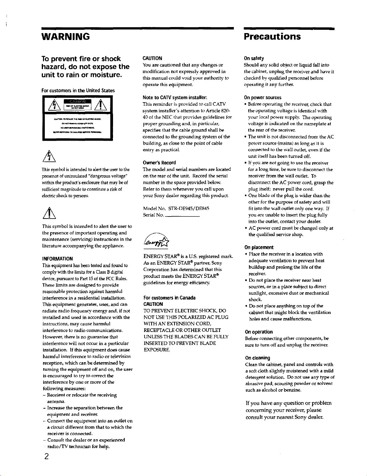
WARNING
Precautions
To prevent fire or shock
hazard, do not expose the
unit to rain or moisture.
For customers in the United States
This symbol is intended to alert the user to the
presence of uninsuiated "dangerous voltage"
within the product's enclosure that may be of
sufficient magnitude to constitute a risk of
electric shock to persons.
LL
This symbol is intended to alert the user to
the presence of important operating and
maintenance (servicing) instructions in the
literature accompanying the appliance.
INFORMATION
This equipment has been tested and found to
comply with the limits for a Class B digital
device, pursuant to Part 15 of the FCC Rules.
These limits are designed to provide
reasonable protection against harmful
interference in a residential installation.
This equipment generates, uses, and can
radiate radio frequency, energy and, if not
installed and used in accordance with the
instructions, may cause harmful
interference to radio communications.
However, there is no guarantee that
interference will not occur in a particular
installation. If this equipment does cause
harmful interference to radio or television
reception, which can be determined by
turning the equipment off and on, the user
is encouraged to try to correct the
interference by one or more of the
following measures:
- Reorient or relocate the _ceiving
antenna.
- Increase the separation between the
equipment and receiver.
- Connect the equipment into an outlet on
a circuit different from that to which the
receiver is connected.
- Consult the dealer or an experienced
radio/TV technician for help.
2
CAUTION
You are cautioned that any changes or
modification not expressly approved in
this manual could void your authority to
operate this equipment.
Note to CAW system installer:
This reminder is provided to call CATV
system installer's attention tn Article 820-
40 of the NEC that provides guidelines for
proper grounding and, in particular,
specifies that the cable ground shall be
connected to the grounding system of the
building, as close to the point of cable
entry as practical.
Owner's Record
The model arid serial numbers are located
on the rear of the unit. Record the serial
number in the space provided below.
Refer to them whenever you call upon
your Sony dealer regarding this product,
Model No. STR-DE945/DE845
Serial No. _
ENERGY STAR ®is a U.S. registered mark.
As an ENERGY STAR ® partner, Sony
Corporation has determined that this
product meets the ENERGY STAR®
guidelines for energy efficiency.
For customers in Canada
CAUTION
TO PREVENT ELECTRIC SHOCK, DO
NOT USE THIS POLARIZED AC PLUG
WITH AN EXTENSION CORD,
RECEPTACLE OR OTHER OUTLET
UNLESS THE BLADES CAN BE FULLY
INSERTED TO PREVENT gLADE
EXPOSURE.
On safety
Should an}' solid object or liquid fall into
the cabinet, unplug the receiver and have it
checked by qualified personnel before
operating it any further.
On power sources
• Before operating the receiver, check that
the operating voltage is identical with
your local power suppl_ The operating
voltage is indicated on the nameplate at
the rear of the receiver.
• The unit is not disconnected from the AC
power source (mains) as long as it is
connected to the wall outlet, even if the
unit itself has been turned off.
• If you are not going to use the _ceiver
for a long time, be sure to disconnect the
receiver from the wall outlet. To
disconnect the AC power cord, grasp the
plug itself; never pull the cord.
• One blade of the plug is wider than the
other for the purpose of safety and will
fit into the wall outlet only one way. If
you are unable to insert the plug fully
into the outlet, contact your dealer.
• AC power cord must be changed only at
the qualified service shop.
On placement
• Place the receiver in a location with
adequate ventilation to prevent heat
buildup and prolong the life of the
receiver.
• Do not place the receiver near heat
sources, or in a place subject to direct
sunlight, excessive dust or mechanical
shock.
• Do not place anything on top of the
cabinet that might block the ventilation
holes and cause malfunctions.
On operation
Before connecting other components, be
sure to turn off and unplug the receiver.
On cleaning
Clean the cabinet, panel and controls with
a soft cloth slightly moistened with a mild
detergent solution. Do not use any type of
abrasive pad, scouring powder or solvent
such as alcohol or benzine.
If you have any question or problem
concerning your receiver, please
consult your nem_st Sony dealer.
About This Manual TABLE OF CONTENTS
The instructions in this manual are for models
STR-DE945 and STR-DE845. Check w)ur model number
by looking at tile upper right corner of the front panel, in
this manual, the STR-DE943 is used for illustration
purposes unless stated otherwise. Any difference in
operation is clearly indicated in the text, tor example,
"STR-DEg45 only."
Type of differences
F_ DE945 DE845
5 audio/video inputs •
4 audio/video inputs •
About area codes
The area code of the player you purchased is shown on the
lower portion of the rear panel (see the illustration below).
Hooking Up the Components
Unpacking 4
Antenna Hookups 5
Audio Component Hookups 6
Video Component Hookups 8
DigitalComponent Hookups 9
5.1CH Input Hookups 11
Other Hookups 12
Hooking Up and Setting Up the
Speaker System 15
Speaker System Hookup 16
Performing Initial Setup Operations 18
Multi Channel Surround Setup 19
Before You Use Your Receiver 23
4
4-XXX-XXX-XX AA
_r _
Area code
Any differences in operation, according to the area code, are
clearly indicated in the text, for examp e, "Models of area
code AA only".
Conventions
• The instructions in this manual describe the controls on
the receiver. You can also use the controls on the
supplied remote if they have the same or similar names
as those on the receiven For details on the use of your
remote, refer to the separate operating instnlctions
supplied with the remote.
• The following icon is used in this manual:
-_'i-Indicates hints and tips for making the task easien
This receiver incorporates Dolby* Digital and Pro Logic
Surround and the DTS** Digital Surround System.
* Mamlfactured under license from Dolby Laboratories.
"Dolby', "AC-3", "Pro Logic" and the doubh,-D symbol [313are
trademarks o] Dolby Laboratories.
Confidential unpublished Works © I992-1997 Dolby Laboratories.
All rights reselved.
**Manufactured under license hvnl Digital Theater Systems, Inc. US
Pat. No. 5,451,¢_42 and other worldwide t_Ttents issued and pending.
"DTS" and "DTS Digital Surrou,d'" are trademarks of Digital
Theater Systems, Inc. © I996 Digital Theater Systenls, hie, All
rights rL_elvcd.
Location of Parts and Basic
Operations 26
Front Panel Parts Description 26
Enjoying Surround Sound 31
Selecting a Sound Field 32
Understanding the Multi-Channel Surround
Displays 36
Customizing Sound Fields 38
Receiving Broadcasts
Direct Tuning 44
Automatic Tuning 45
Preset Tuning 45
43
Other Operations 47
Naming Preset Stations and Program Sources
Recording 48
Using the Sleep Timer 49
Adjustments Using the SET UP Button 50
CONTROLAIII Control System 51
48
Additional Information 53
Troubleshooting 53
Specifications 55
Glossary 58
Tables of Settings Using SUR, LEVEL, EQ, and SET
UP buttons 59
Index 61 3
Hooking Up
Unpacking
the
Components
This chapter describes how to connect
various audio and video components
to the receiver. Be sure to read the
sections for the components you have
before you actually connect them to
the receiver.
Check that you received the following items with the
remote:
• FM wire antenna (l)
• AM loop antenna (1)
• 1,R6 (size-AA) alkaline batteries (3)
Models of area code U, CA onh,
• Audk)/vide_}/control S connecting cord (1)
• Control S connecting c_rd (1 }
STR-DE945 only
• Remote commander RM-L]304 (remote) (1)
STR-DE845 only
• Remote commander RM-LP204 (remote) (1)
Inserting batteries into the remote
Insert LR6 (size-AA) alkaline batteries with the + and -
properly oriented in the battery compartment. When
using the remote, point it at the remote sensor [] on the
receiver.
For details, refer to the operating instructions supplied
with your remote.
"_1"When to replace batteries
Under normal conditions, the batteries should last for about
3 months. When the remote no longer operates the receiver,
replace all batteries with new ones.
Notes
• Do not leave the remote in an extremely hot or humid place.
• Do not use a new batte D' with an old one.
• Do not expose the remote _ensor to direct sunlight or lighting
apparatuses. Doing so may cause a malfunction.
• If you don't use the remote for an extended period of time,
remove the batteries to avoid possible damage from battery
leakage and corrosion.
• This remote is designed for use with alkaline batteries only. Do
not use a combination of different battery types.
Before you get started
• Turn off the power to all components before making
any connections.
• Do not connect the AC power cord until all of the
connections are completed.
• Be sure to make connections firmly to avoid hum and
noise.
• When connecting an audio/video cord, be sure to
match the color-coded pins to the appropriate jacks on
the components: yellow (video) to yellow; white (left,
audio) to white; and red (right, audio) to red.
4
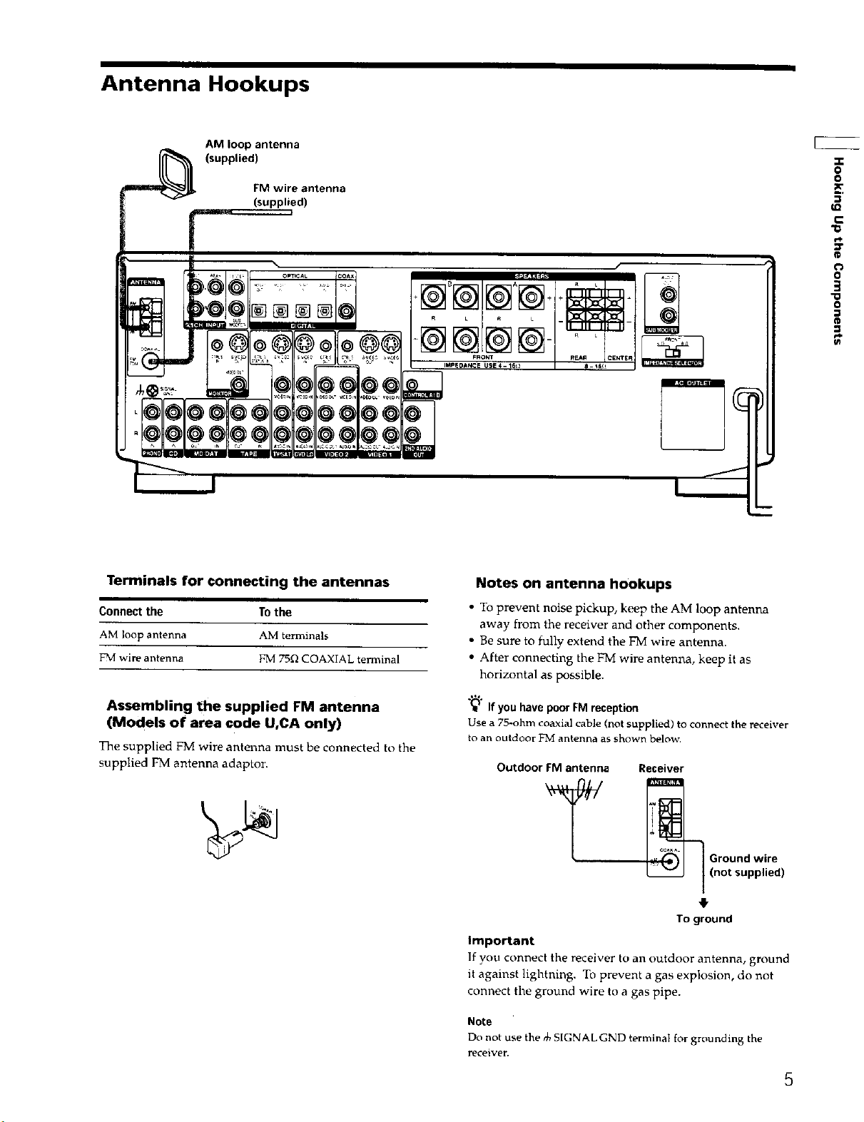
Antenna Hookups
AM loop antenna
(supplied)
FM wire antenna
(supplied)
"o
o
o
e=
_ ,_. _ •E_ Op,lCAL coax
% r
@ 0 + -
*b:COL"
Terminals for connecting the antennas
Connect the To the
AM loop antenna AM terminals
FM wire antenna FM 75f_ COAXIAL terminal
+ + + .
Notes on antenna hookups
• To prevent noise pickup, keep the AM loop antenna
away from the receiver and other components.
• Be sure to fully extend the FM wire antenna.
• After connecting the FM wire antenna, keep it as
horizontal as possible.
C
@
oi
o
3
0
e_
Assembling the supplied FM antenna
(Models of area code U,CA only)
The supplied FM wire antenna must be connected to the
supplied FM antenna adaptor.
"(_ If youhave poorFMreception
Use a 75-ohm coaxial cable (not s_pplied) to connect the receiver
to an outdoor FM antenna as shown below,
Outdoor FM antenna
Receiver
_ Ground wire
] (not supplied)
To ground
Important
]f you connect the rece vet ( a _outdoor antenna, ground
it against lightning. To prevent a gas explosion, do not
connect the ground wire to a gas pipe.
Note
Do not use the _ SIGNAL GND termina_ for grounding the
receiver,
5
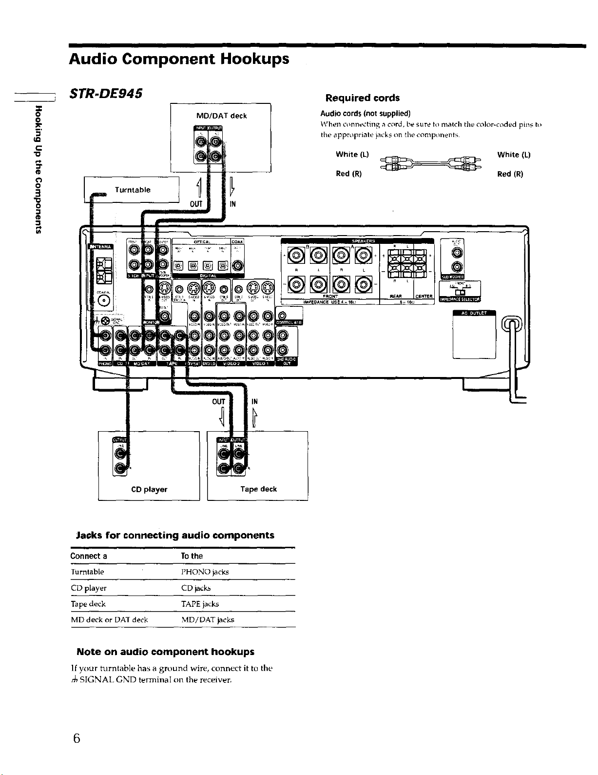
Audio Component Hookups
=r
o
o
:1€-
5'
112
€
"0
_r
@
€
3
o
®
STR-DE945
Turntable ] _J
MD/DAT deck
OUT IN
Required cords
Audio cords (not supplied)
When connecting a c_rd, be sure to match the color<(,aded pills to
tile appropriate jacks on the components.
White (L) White (L)
Red (R) Red (R)
OUT IN
CD player Tape deck
Ja0ks for connecting audio components
Connect a To the
Turntable PHONO jacks
CD player CD jacks
Tape deck TAPE jacks
MD deck or DAT deck MD/DAT jacks
Note on audio component hookups
If your turntable has a ground wire, connect it to the
SIGNAL GND terminaI on the receiver.
6
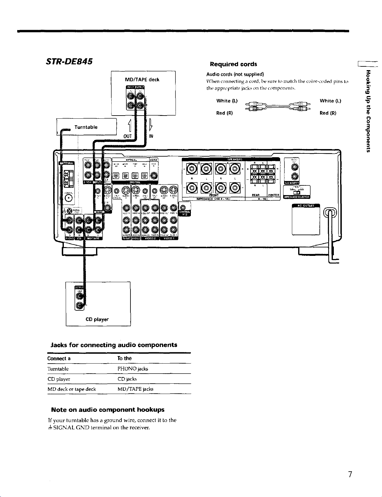
STR-DE845
Turntable
MDTTAPE deck
OUT IN
[]@
Required cords
Audio cords (not supplied)
_,\_hen conllecting a coix_, b_' sure to match the cold,r-coded pins to
the appropriate iack_ on the conlponents.
White (L) White (L)
Red (R) Red (R)
"r
o
o
c
o*
t_
o
3
o
¢D
CD player
Jacks for connecting audio components
Connect a To the
Turntable PHONO jacks
CD player CD jacks
MD deck or tape deck MD/TAPE jacks
Note on audio component hookups
If your turntable has a ground wire, connect it to the
SIGNAL GND terminal on the receiver.
7
Video Component Hookups
X
0
0
_0
f_
0
3
"O
0
TV or satellite tuner DVD or LD player
Audio/video cords (net supplied)
When connecting a cord, be sure to match the color-coded pins to
tile appropriate jacks on tile components.
Yellow (video) _ Yellow (video)
White (L/audio)_ White {L/audio)
Red (R/audio) Red (R/audio)
Video cord for connecting a TV monitor
You can use the video cord of tile supplied audio/video/control
S cord. (Models of area ct_de U CA only. See page 12 for details).
@
Required cords
To the front panel
m Camcorder
or video
game
(STR-DE945
only)
TV monitor
Jacks for connecting video components
Connect a 1"othe
TV or satellite tuner TV/SAT jacks
VCR VIDEO 1 jacks
Additional VCR VIDEO 2 jacks
DVD or LD player DVD/LD jacks
TV monitor 11 MONITOR VIDEO OUT jack
Camcorder or video game VIDEO 3 INPUT jacks on the
front panel (STR-DE945 onlv)
1) For STR-DE945, vou can display the SURROUND, LEVEL
EQUALIZER parameters by pressing the ON SCREEN button
on the remote.
IN
OUT
IN
VCR
Note on video component hookups
You can connect your TV's audio output jacks to the TV/
SAT AUDIO IN jacks on the receiver and apply sound
effects to the audio from the TV. In this case, do not
connect the TV's video output jack to the TV/SAT VIDEO
IN jack on the receiver. If you are connecting a separate
TV tuner (or satellite tuner), connect both the audio and
video output jacks to the receiver as shown above.
"_i" When using the S.videojacks instead of the video jacks
Your monitor must also be cor, ne,cted via an S-video jack. S-video
signals are on a separate bus from the video signals and will not
be output through the video jacks.
8
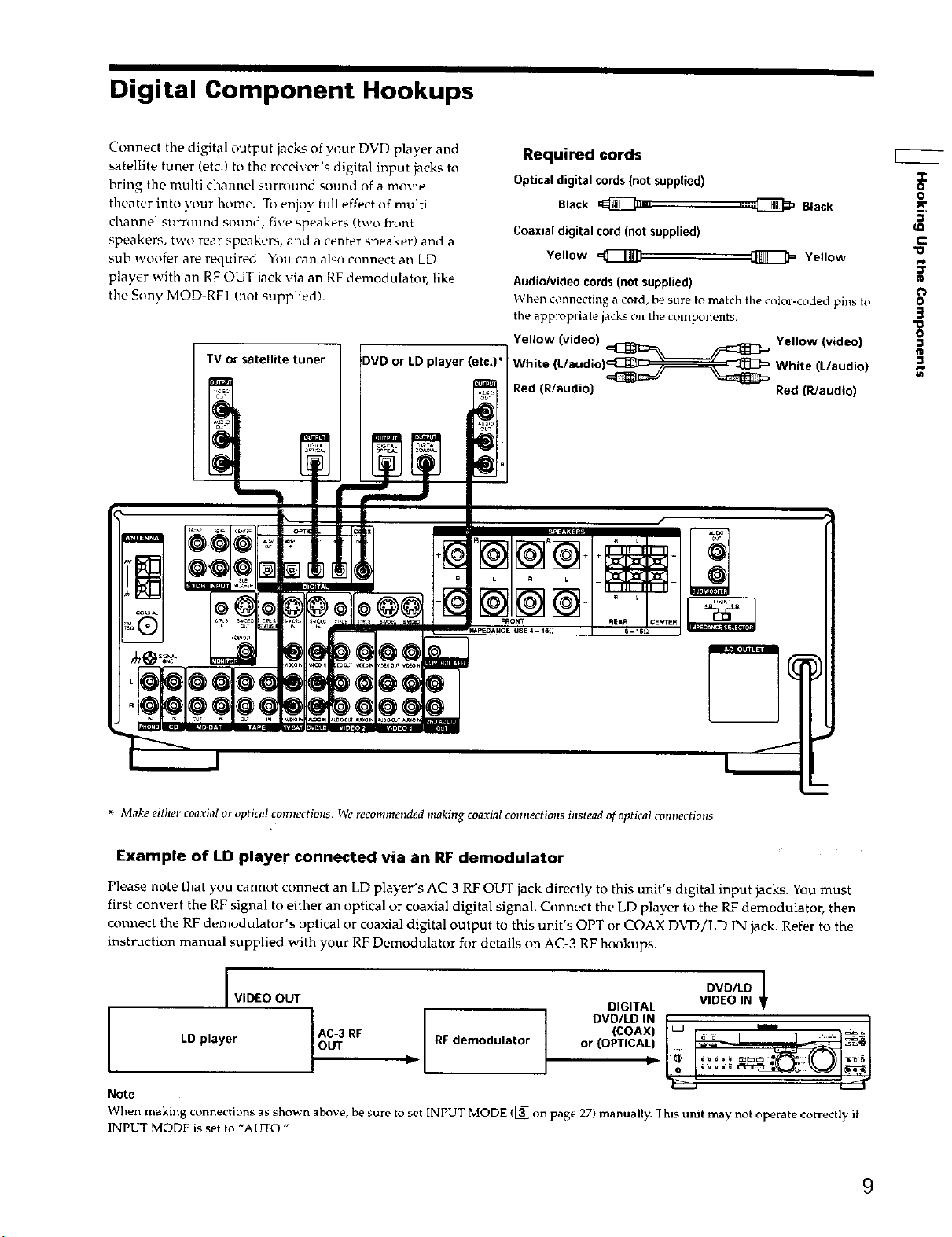
Digital Component Hookups
Connect tile digital output jacks of your DVD player and
satellite tuner (etc.) to the recei\ er's digital input jacks to
bring the multi channel surround sound of a movie
theater into your home. To enjoy full effect of multi
channel snrround sound, five speakers (two front
speakers, two rear speakers, and a center speaker) and a
sub wouter are required. You can also connect an LD
player with an RF OUT jack via an RF demodulator, like
the Sony MOD-RF] (not supplied).
TV or satellite tuner
DVD or LD player (etc.)" White (L/audio)_ White (L/audio)
Required cords
Optical digital cords (not supplied)
Black _=,
Coaxial digital cord (not supplied)
Yellow
Audio/video cords (not supplied)
"When connecting a cord, be sure to match the color-coded pins to
the appropriate iacks on the components.
Yellow (video) _ _ Yellow (video)
Red (R/audio) Red (R/audio)
•_ Black
Yellow
I1=
-p
o
o
_r
5'
r-
o
3
o
¢D
* Make either coarial or optical connections. We recolnmended making coaxial comlections instead of optical connections.
Example of LD player connected via an RF demodulator
Please note that you cannot connect an LD player's AC*3 RF OUT jack directly to this unit's digital input jacks. You must
first convert the RF signal to either an optical or coaxial digital signal. Connect the LD player to the RF demodulator, then
connect the RF demodulator's optical or coaxial digital output to this unit's OPT or COAX DVD/LD IN jack. Refer to the
instruction manual supplied with your RF Demodulator for details on AC-3 RF hookups.
I DVD/LD
VIDEO OUT DIGITAL VIDEO IN
LD player AC-3 RF RF demodulator or (OPTICAL)
Note
When making connections as shown above be sure to set INPUT MODE [_ on page 27 manua v. Th sun may no opera e c( rrec y f
INPUT MODE is set to "AUTO."
9
Digital Component Hookups
Connect the digital output jacks of your MD or DAT deck
,I-
o
o
to the receiver's digital input jack and connect the digital
input jacks of your MD or DAT deck to the receiver's
digital output jack. These connections allow you to make
_2
r-
O
3
"o
o
t.t
kn
digital recordings of a CDs played back through your
DVD (or LD player) and satellite broadcasts.
MD or OAT deck
OUT IN OUT
IN
Required cords
Opticaldigitalcords(notsupplied)
Black _-:'
Audio cords (not supplied)
When connecting a cord, be sure to r=latch tile color-coded pins tt_
the appropriate jacks oil the components.
White (L) White (L)
Red (R) Red (R)
....._ Black
@
Notes
• Please note that you cannot make a digital recording of a digital multi channel surround signal.
• To make a digital recording from your CD player, connect the CD player's digital output directly to the digital input on your MD or DAT
deck. Refer to the instructions supplied with your CD player and MD or DAT deck for details.
• The DVD/LD IN OPTICAL and COAX jacks are compatible with 96 kHz, 48 kHz, 44.1 kHz and 32 kHz sampling frequencies. The other
OIYFICAL jacks are compatible with 48 kHz, 44.1 kHz and 32 kHz sampling frequencies.
• It is not possible to record analog signals to TAPE and VIDEO with only digital connections. To record analog signals, make analog
connections. To record digital signals, make digital connections.
• Input signals with 96 kHz sampling frequencies to the DVD/LD IN OPTICAL or COAX jacks. Using other jacks may result in
intermittent sound.
10
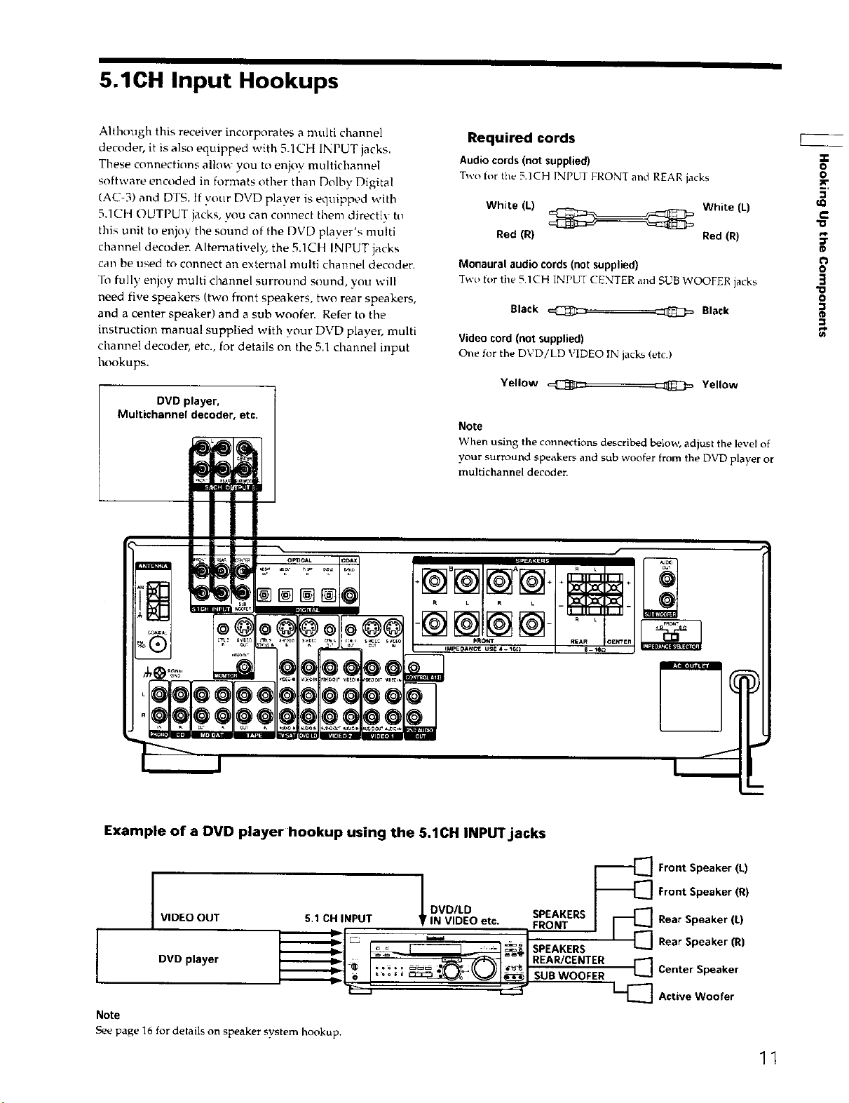
5.1CH Input Hookups
Although this receiver incorporates a multi channel
decoder, it is also equipped with 5.1CH INPUT jacks.
These connections allow you to enjoy multichannel
software encoded in formats other than Dolby Digital
(AC-3) and DTS. If your DVD player is equipped with
5.1CH OUTPUT jacks, you can connect them directly to
this unit to enjoy the sound of the DVD p/aye_-'s n'_u_ti
channel decoden Alternatively, the 5.1CH INPUT jacks
can be used to connect an external multi channe! decoder.
To fully enjoy multi channel surround sound, you will
need five speakers (two front speakers, two rear speakers,
and a center speaker) and a sub woofer. Refer to the
instruction manual supplied with your DVD player, multi
channel decoder, etc., for details on the 5,1 channel input
hookups.
DVD player,
Multichannel decoder, etc.
Required cords
Audio cords (not supplied)
Two _or the 5.1CH iNPUT FRONT and REAI-I jacks
White (L) White (L)
Red (R} Red (fl}
Monaural audio cords (not supplied)
Two for the 5.1CH INPbq CENTER and SUB WOOFER jacks
Black ==_ =_ Black
Video cord (not supplied)
One for the DVD/LD VIDEO IN jacks (etc.)
Yellow _ Yellow
Note
When using the connections described below, adjust the level of
your surround speakers and sub woofer from the DVD player or
multichannel decoden
o
o
w,
€
"o
(D
o
3
*o
o
e_
@@@
Example of a DVD player hookup using the 5.1CH INPIZriacks
I VIDEO OUT
4
Note
See page 16 for details on speaker system hookup.
DVD player
5.1 CH INPUT ! IN VIDEO etc. FRONT
= _o _ _dSPEAKERS
II_ ===.= , .
DVDILD SPEAKERS
--11 "' ; x -' SUB WOOFER
° JRE,, EN'FER
"_'_ Front Speaker (k)
"_'[_ Front Speaker (R)
Rear Speaker (L)
Rear Speaker (R)
[_] Center Speaker
1--'[_ Active Woofer
11
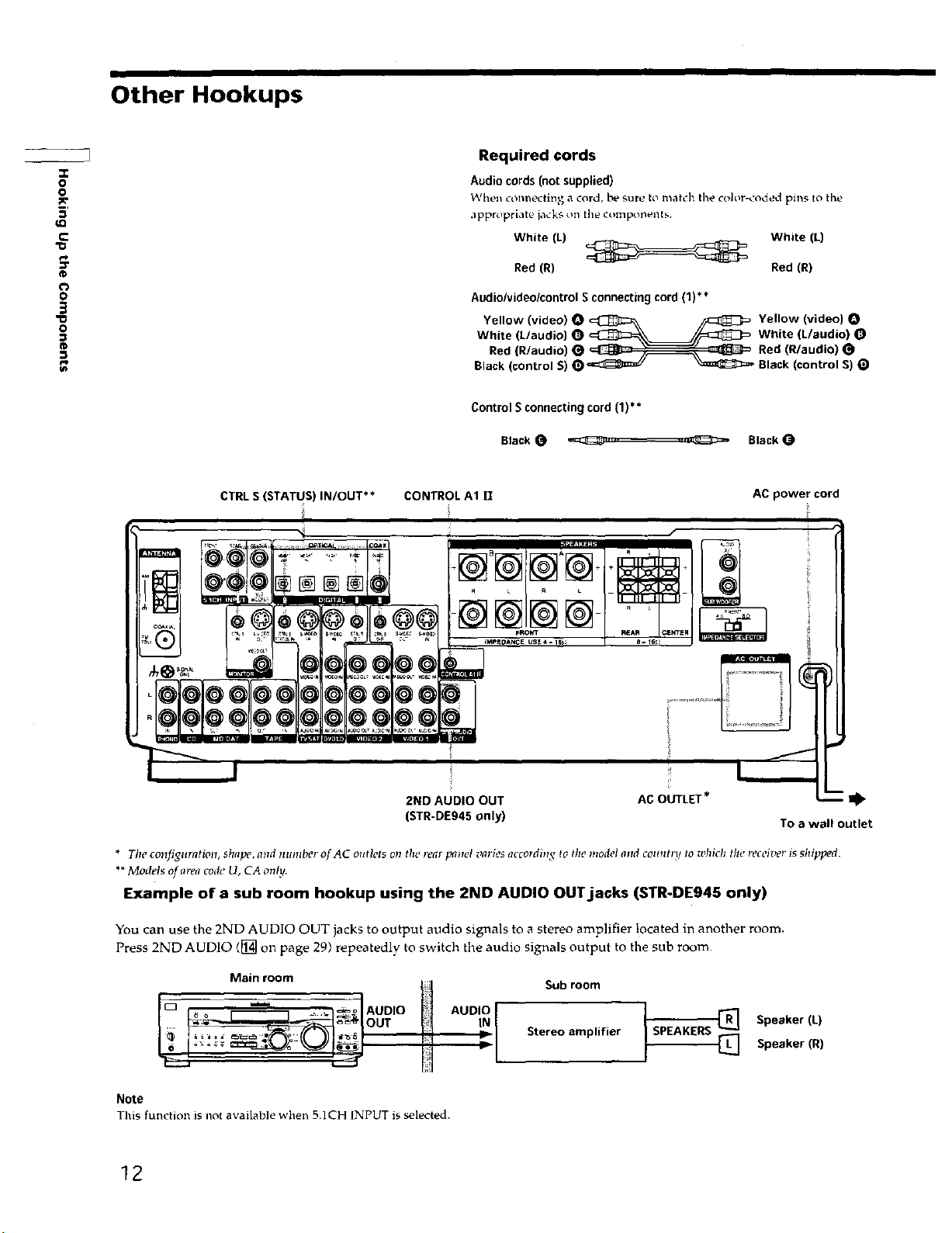
Other Hookups
Required cords
o
o
5'
c
"o
Audio cords (not supplied)
When connecting a cord, be sure to match the color-coded pins to the
,lppr_priate jacks on the components.
White (L) White (L)
Red (R) Red (R)
o
'o
o
®
CTRL S (STATUS) IN/OUT** CONTROL A1 /l AC power cord
Audio/video/control Sconnecting cord (1)**
Yellow (video) O _ /_ Yellow (video) O
White (L/audio) O _ //_ White (L/audio) O
Red (R/audio) _ _ _ Red (R/audio)
Black (control S) O c_=_/ _ Black (control S) t_
Control S connecting cord (1)**
BlackO _ .......... _ Black(_
2ND AUDIO OUT AC OUTLET* I_
(STR-DE945 only) To a wall outlet
* The configuration, shape, alzd number of AC outlets on the rear panel varies according to the model and countrl to which tile receiver is shipped.
**Models of area code U, CA only.
Example of a sub room hookup using the 2ND AUDIO OUT.jacks (STR-DE945 only)
You can use the 2ND AUDIO OUT jacks to output audio signals to a stereo amplifier located in another room.
Press 2ND AUDIO ([_ on page 29) repeatedly to switch the audio signals output to the sub room.
Main room
CD .... _ AUDO AUDO
OUT IN
Note
This functiorL is not available when 5.1CH INPUT is selected.
Sub room
Stereo amplifier
SPEAKERS
Speaker (L)
Speaker (R)
12
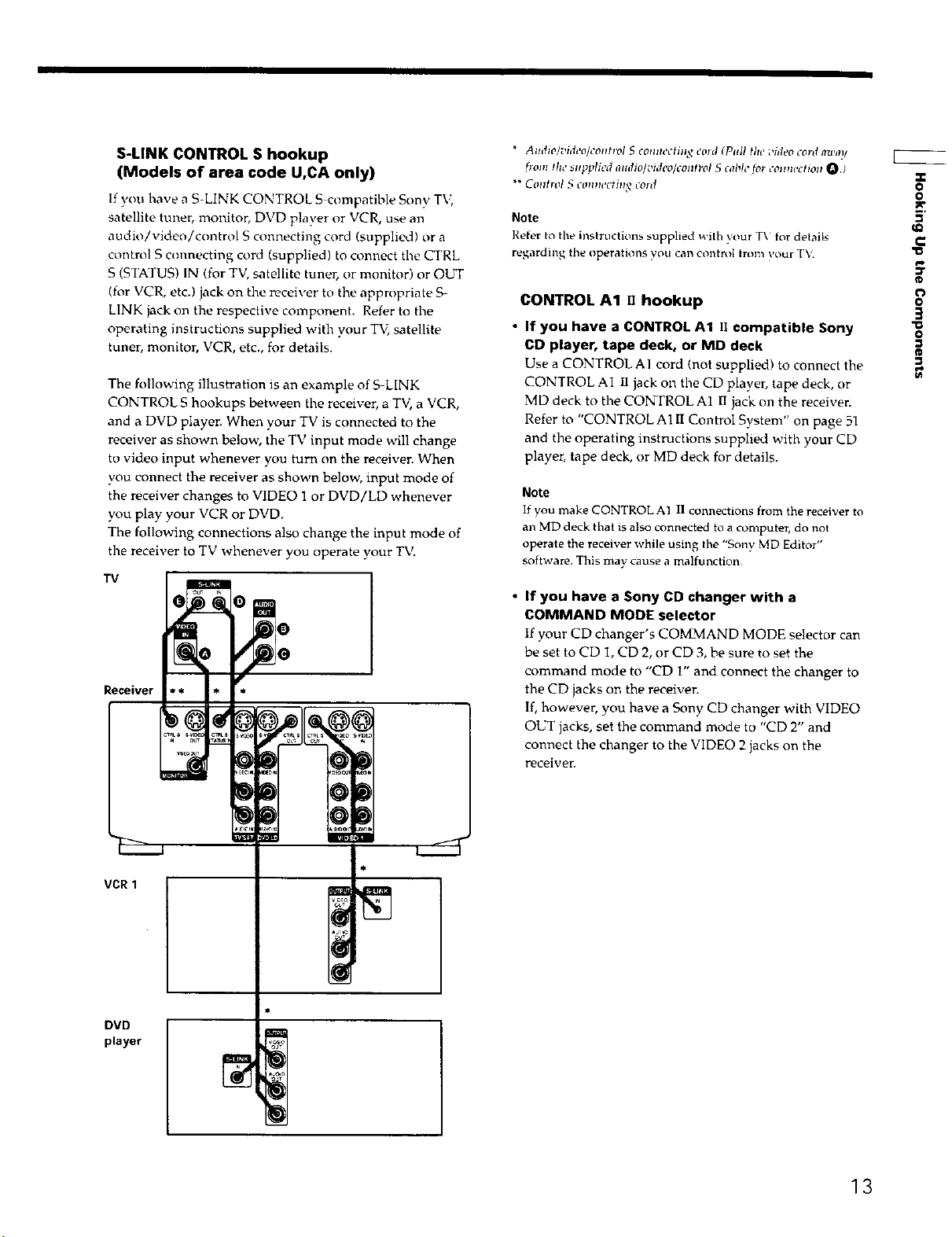
S-LINK CONTROL S hookup
(Models of area code U,CA only)
If you have a S-LINK CONTROL S compatible Sony TV,
satellite tuner, monitor, DVD player or VCR, use an
audio/video/control S connecting cord (supplied) or a
control S connecting cord (supplied) to connect the CTRL
S (STATUS) IN (for TV, satellite tuner, or monitor) or OUT
(for VCR, etc.) jack on the receiver to the appropriate S-
LINK jack on the respective component. Refer to the
operating instructions supplied with your TV, satellite
tuner, monitor, VCR, etc., for details.
The following illustration is an example of S-LINK
CONTROL S hookups between the receiver, a TV, a VCR,
and a DVD player. When your TV is connected to the
receiver as shown below, the TV input mode will change
to video input whenever you turn on the receiver. When
you connect the receiver as shown below, input mode of
the receiver changes to VIDEO 1 or DVD/LD whenever
you play your VCR or DVD.
The following connections also change the input mode of
the roceiver to TV whenever you operate your TV.
TV
Receiver
* Audio]video]control S conm'ctinq cold (Pull the video cord awal/
h'om the supplied nudio/i,ideo/contl-ol S cable fo! colnlechon O.)
** Control S connecting tosd
Note
Refer to the instructions supplied with your T\ for details
regarding the operations you can control Irom vour "[\.
• k
CONTROL A1 . hookup
• If you have a CONTROL A1 I1 compatible Sony
CD player, tape deck, or MD deck
Use a CONTROLAI cord (not supplied) to connect the
CONTROL AI ll jack on the CD player, tape deck, or
MD deck to the CONTROL A1 II jack on the receiver.
Refer to "CONTROL AllI Control System" on page 51
and the operating instructions supplied with your CD
player, tape deck, or MD deck for details.
Note
If you make CONTROL A] II connections from the receiver to
an MD deck that is also connected to a computer, do not
operate the receiver while using the "Sony MD Editor"
software. This may cause a malfunction
• If you have a Sony CD changer with a
COMMAND MODE selector
If your CD changer's COMMAND MODE selector can
be set to CD I, CD 2, or CD 3, be sure to set the
command mode to "CD 1" and connect the changer to
the CD jacks on the receiver.
If, however, you have a Sony CD changer with VIDEO
OUT jacks, set the command mode to "CD 2" and
connect the changer to the VIDEO 2 jacks on the
receiver.
"O
"13
Z
O
o
w
5'
c
o
3
0
VCR1
DVD
player
13
Other Hookups
u2
"o
"o
,,r
o
o
m,
=
c
(D
o
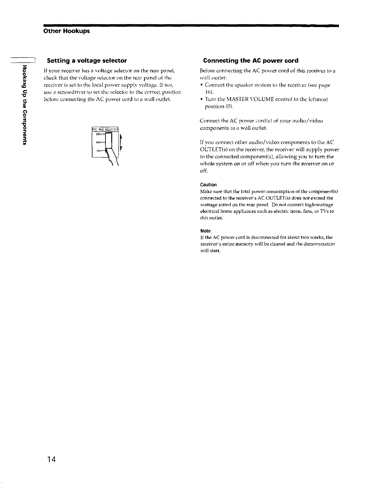
If your receiver has a voltage seledor on tile rear panel,
check that the voltage selector on the rear panel of the
receiver is set to the local power supply voltage. If not,
use a screwdriver tu set the selector to the correct position
before connecting the AC power cord to a wall outlet.
g
o
Setting a voltage selector
Connecting the AC power cord
Before connecting the AC power cord of this receiver to a
wall outlet:
• Connect the speaker system to the receiver (see page
16).
• Tun1 the MASTER VOLUME contro! to the leftmost
position (0).
Connect the AC power cord(s) of )'our audio/video
components to a wail outlet.
If you connect other audio/video components to the A'C
OUTLET(s) on the receiver, the receiver will supply power
to the connected component(s), allowing you to turn the
whole system or_ or off when you turn the receiver on or
off.
Caution
Make sure that the total power consumption of the component(s)
connected to the receiver's AC OUTLET(s) does not exceed the
wattage stated on the rear panel. Do not connect high-wattage
electrical home appliances such as electric irons, fans, or TVs to
this outlet.
Note
If the AC power cord is disconnected for about two weeks, the
receiver's entire memo D' will be cleared and the demonstration
will start.
14
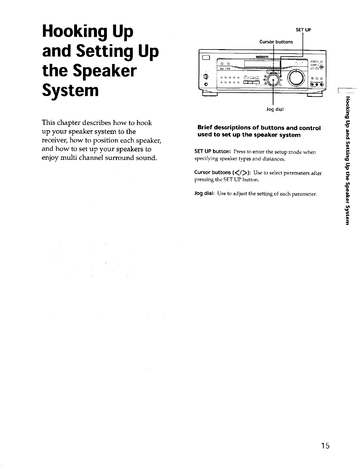
Hooking Up
and Setting Up
the Speaker
SET UP
Cursorbuttons J
System
This chapter describes how to hook
up your speaker system to the
receiver, how to position each speaker,
and how to set up your speakers to
enjoy multi channel surround sound.
Jog dial
Brief descriptions of buttons and control
used to set up the speaker system
SET UP button: Press to enter the setup mode whe1_
specifying speaker types and distances.
Cursor buttons (<_/_): Use to select parameters after
pressing the SET UP button.
Jog dial: Use to adjust the setting of each parameter.
o
o
tO
m
tn
®
t=t
m,
a_
"o
_r
"D
ca
,,q
¢P
15

Speaker System Hookup
Required cords
Speaker cords (not supplied)
One for each front, rear, and center speaker
-o
"O
11
o
o
5'
r-
¢L
5'
r-
IT
r¢
3
(+)
(-)
Monaural audio cord (not supplied)
One for an active sub woofer
Black _
Black
Front speaker (R) Front speaker (L)
FRONT
SPEAKERS B
Centerspeaker
@ ©
IMPEDANCE
SELECTOR
@ 0
Rear speaker (R)
Terminals for connecting the speakers
Connect the To the
Front speakers (8 or 4* ohm) SPEAKERS FRONT A terminals
Additional pair of front SPEAKERS FRONT B terminals
speakers (8 or 4* ohm)
Rear speakers (8 ohm) SPEAKERS REAR terminals
Center speaker (8 ohm) SPEAKERS CENTER terminals
Active sub woofer SUB WOOFER AUDIO OUT
jack**
* See "'Speaker inlpedance" opt tile _lexl pa_e
** "_hlr ca_ co _ec a nctive s_rb woo_r to eithcr of tht, two iacks The
r_'nlaillmg i:ack c_;l hi" ii_ed to co_lt_ect ct second active slrb _oofer
@
Rear speaker (L)
Notes on speaker system hookup
• Twist the stripped ends of the speaker cords about
2/3 inch (10 mm). Be sure to match the speaker cord to
the appropriate terminal on the components: + to + and
- to -. If the cords are reversed, the sound will be
distorted and will lack bass.
• Ifyou use front speakers with low maximum irrput
rating, adjust the volume carefully to avoid excessive
output on the speakers.
Active sub woofer
16
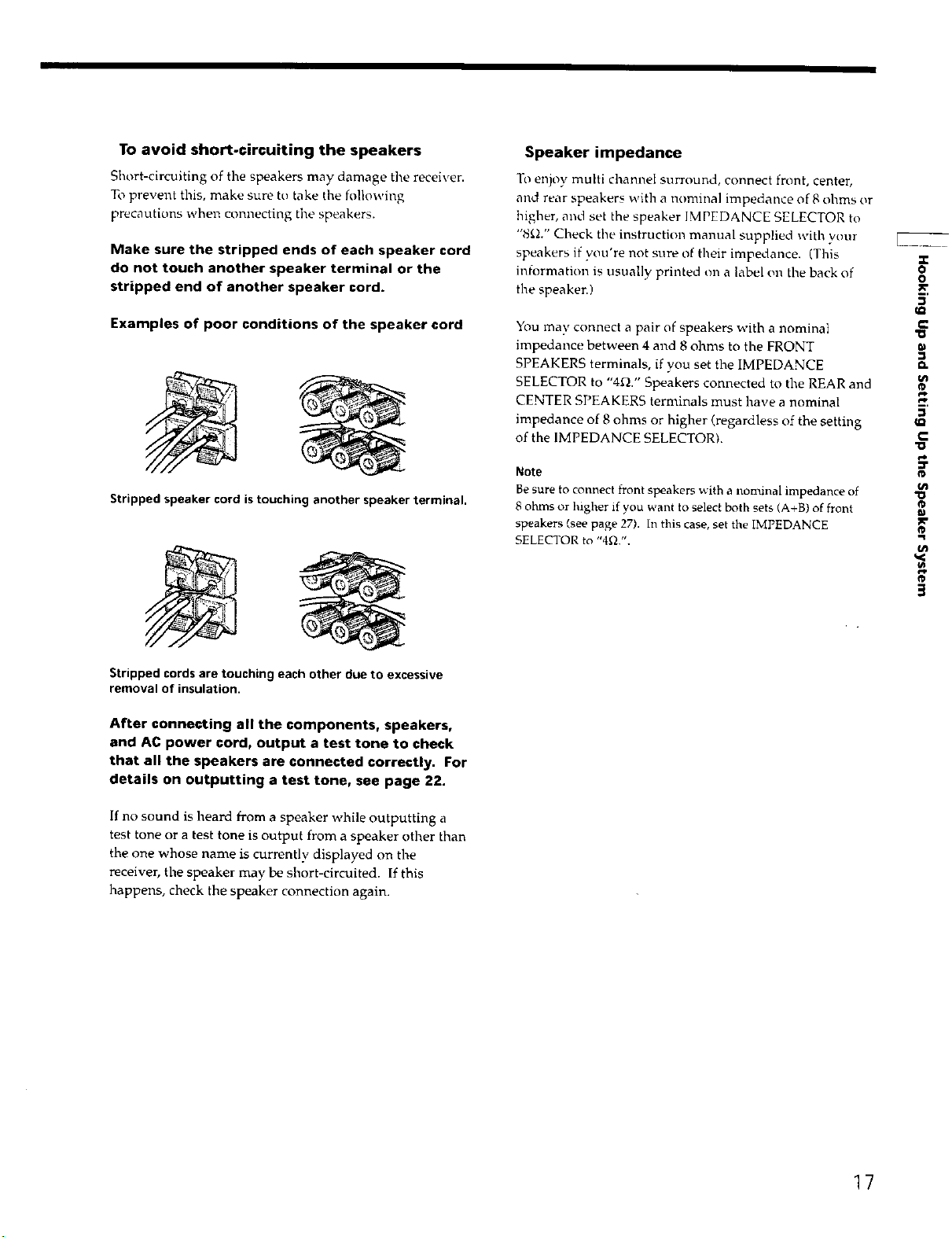
To avoid short-circuiting the speakers
Short-circuiting of tile speakers may damage tile receiver.
To prevent this, make sure to take the following
precautions when connecting the speakers.
Make sure the stripped ends of each speaker cord
do not touch another speaker terminal or the
stripped end of another speaker cord.
Speakerimpedance
To enjoy multi channel surround, connect front, center,
and rear speakers with a nominal impedance of 8 ohms or
higher, and set the speaker IMPEDANCE SELECTOR to
"8_d." Check the instruction manual supplied with your
speakers if you're not sure of their impedance. (This
intormation is usually printed on a label on the back of
the speaken)
.r
o
o
Examples of poor conditions of the speaker cord
Stripped speaker cord is touching another speaker terminal.
Stripped cords are touching each other due to excessive
removal of insulation.
After connecting all the components, speakers,
and AC power cord, output a test tone to check
that all the speakers are connected correctly. For
details on outputting a test tone, see page 22.
You may connect a pair of speakers with a nominal
impedance between 4 and 8 ohms to the FRONT
SPEAKERS terminals, if you set the IMPEDANCE
SELECTOR to "4f_." Speakers connected to the REAR and
CENTER SPEAKERS terminals must have a nominal
impedance of 8 ohms or higher (regardless of the setting
of the IMPEDANCE SELECTOR).
Note
Be sure to connect front speakers with a nominal impedance of
8 ohms or higher if you want to select both sets (A+B) of front
speakers (see page 27). In this case, set the iMPEDANCE
SELECTOR to "4f_.".
€
D.
kn
C
"o
"o
x"
3
If no sound is heard from a speaker while outputting a
test tone or a test tone is output from a speaker other than
the one whose name is currently displayed on the
receiver, the speaker may be short-circuited. If this
happens, check the speaker connection again.
17
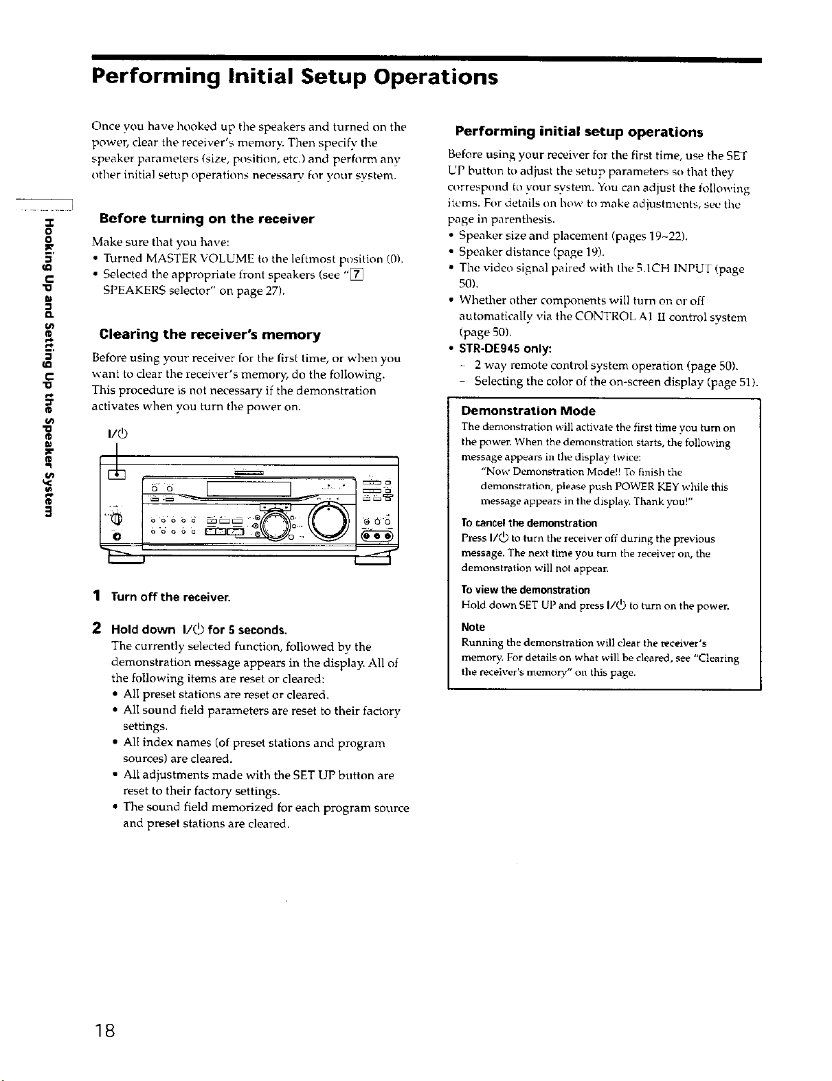
Performing Initial Setup Operations
Once you have hooked up the speakers and turned on the
Performing initial setup operations
power, clear the receiver's memory. Then specify the
speaker parameters/size, positirnl, etc.) and perhwm any
other initial setup operations necessary for your system.
Before using your receiver for the first time, use the SET
UP button to adjust the setup parameters so that they
correspond to your system. You can adjust the following
items. For details on how to make adiustments , see the
X
o
o
5'
Io
C
"u
Before turning on the receiver
Make sure that you have:
• Turned MASTER VOLUME to the leftmost position (0).
• Selected the appropriate front speakers (see "[_
SPEAKERS selector" on page 27).
page in parenthesis.
• Speaker size and placement (pages 19-22).
• Speaker distance (page 19).
• The video signal paired with the 5.1CH INPUT (page
50).
• Whether other components will turn on or off
automatically via the CONTROL A1 II control system
€
Clearing the receiver's memory
Before using your receiver for the first time, or when you
C
"o
rl,
want to clear the receiver's memory, do the following.
This procedure is not necessary if the demonstration
activates when you turn the power on.
"o
€
Ir
ii_b
F_ m
3
1
Turn off the receiver.
2
Hold down I/_ for 5 seconds.
The currently selected function, followed by the
demonstration message appears in the display. All of
the following items are reset or cleared:
(page 50).
• STR-DE945 only:
- 2 way remote control system operation (page 50).
- Selecting the color of the on-screen display (page 51).
Demonstration Mode
The demonstration will activate the first time you turn on
the power. When the demonstration starts, the following
message appears in the display twice:
"Now Demonstration Mode!! To finish the
demonstration, please push POWER KEY while this
message appears in the display. Thank you!"
To cancel the demonstration
Press I/_ to turn the receiver off during the previous
message. The next time you turn the receiver on, the
demonstration will not appean
To view the demonstration
Hold down SET UP and press I/_) to turn on the power.
Note
Running the demonstration will clear the receiver's
memory. For details on what will be cleared, see "Clearing
the receiver's memory" on this page.
• All preset stations are reset or cleared.
• All sound field parameters are reset to their factory
settings.
• All index names (of preset stations and program
sources) are cleared.
• All adjustments made with the SET UP button are
reset to their factory settings.
• The sound field memorized for each program source
and preset stations are cleared.
18
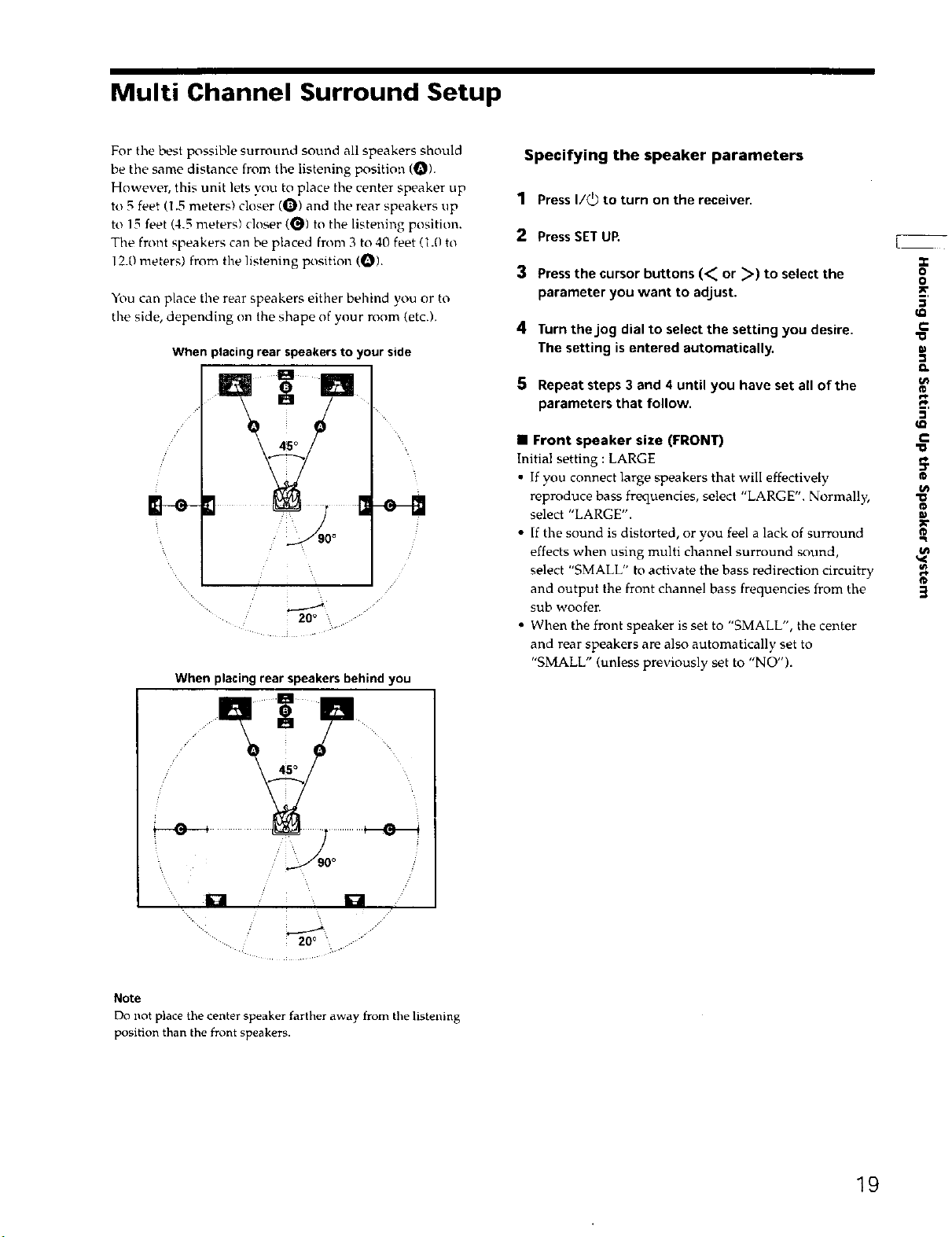
Multi Channel Surround Setup
For the best possible surround sound all speakers should
be the same distance from the listening position (O).
However, this unit lets you to place the center speaker up
to 5 feet (1.5 meters} closer (O) and the rear speakers up
to 15 feet (4.5 meters) closer (_) to the listening position.
The front speakers can be placed from 3 to 40 feet (1.0 to
12.0 meters) from the listening position (_).
You can place the rear speakers either behind you or to
the side, depending on the shape of your room (etc.).
When placingrear speakersto your side
g
When placing rear speakers behind you
Specifying the speaker parameters
1 PressI/_ to turn on the receiver.
2 PressSET UR
3 Pressthe cursor buttons (< or >) to select the
parameter you want to adjust.
4 Turn thejog dial to select the setting you desire.
The setting isentered automatically,
5 Repeat steps 3 and 4 until you have set all of the
parameters that follow.
• Front speaker size (FRONT)
Initial setting : LARGE
• If you connect large speakers that will effectively
reproduce bass frequencies, select "LARGE". Normally
select "LARGE".
• If the sound is distorted, or you feel a lack of surround
effects when using multi channel surround sound,
select "SMALL" to activate the bass redirection circuitry
and output the front channel bass frequencies from the
sub woofer.
• When the front speaker is set to "SMALL", the center
and rear speakers are also automatically set to
"SMALL" (unless previously set to "NO").
"o
..r
0
o
c
€
__,
C
:T
fD
R
R
3
u Z U
45°
20°
Note
Do not place the center speaker farther away from t le ste _ ng
position than the front speakers.
19
 Loading...