

Page 1

FM Stereo
FM-AM Receiver
3-856-169-31(1)
Operating Instructions
Manual de Instrucciones
CH
EN
EN
E
P
C
S
STR-DE705
© 1996 by Sony Corporation
Page 2

WARNING
To prevent fire or shock
hazard, do not expose
the unit to rain or
moisture.
Precautions
On safety
• Should any solid object or liquid fall
into the cabinet, unplug the receiver
and have it checked by qualified
personnel before operating it any
further.
On power sources
• Before operating the receiver, check
that the operating voltage is identical
with your local power supply. The
operating voltage is indicated on the
nameplate at the rear of the receiver.
• The unit is not disconnected from the
AC power source (mains) as long as it
is connected to the wall outlet, even if
the unit itself has been turned off.
• If you are not going to use the
receiver for a long time, be sure to
disconnect the receiver from the wall
outlet. To disconnect the AC power
cord, grasp the plug itself; never pull
the cord.
• One blade of the plug is wider than
the other for the purpose of safety
and will fit into the wall outlet only
one way. If you are unable to insert
the plug fully into the outlet, contact
your dealer.
• AC power cord must be changed only
at a qualified service shop.
On placement
• Place the receiver in a location with
adequate ventilation to prevent heat
buildup and prolong the life of the
receiver.
• Do not place the receiver near heat
sources, or in a place subject to direct
sunlight, excessive dust or
mechanical shock.
• Do not place anything on top of the
cabinet that might block the
ventilation holes and cause
malfunctions.
On operation
• Before connecting other components,
be sure to turn off and unplug the
receiver.
On cleaning
• Clean the cabinet, panel and controls
with a soft cloth slightly moistened
with a mild detergent solution. Do
not use any type of abrasive pad,
scouring powder or solvent such as
alcohol or benzine.
If you have any question or problem
concerning your receiver, please
consult your nearest Sony dealer.
EN
2
Page 3

About This Manual
TABLE OF CONTENTS
Conventions
• The instructions in this manual
describe the controls on the receiver.
You can also use the controls on the
remote if they have the same or
similar names as those on the
receiver.
• A “Quick Reference Guide” is
supplied on page 29.
• The “Remote Button Descriptions”
section on page 27 provides an
overview of the remote buttons.
• The following icons are used in this
manual:
Indicates that you can use only
the remote to do the task.
Indicates hints and tips for
making the task easier.
This receiver incorporates the Dolby
Pro Logic Surround system.
Manufactured under license from Dolby
Laboratories Licensing Corporation.
DOLBY, the double-D symbol a and
“PRO LOGIC” are trademarks of Dolby
Laboratories Licensing Corporation.
Getting Started
Unpacking 4
Hookup Overview 4
Antenna Hookups 5
Audio Component Hookups 5
Speaker System Hookups 6
TV/VCR Hookups 7
AC Hookups 8
Before You Use Your Receiver 8
Receiver Operations
Selecting a Component 9
Receiving Broadcasts 10
Presetting Radio Stations 11
Indexing 12
Recording 13
Using the Sleep Timer 14
Using Sound Fields
Using Pre-programmed Sound Fields 15
Taking Advantage of the Sound Fields 16
Customizing Sound Fields 16
Getting the Most Out of Dolby Pro Logic Surround Sound 18
EN
Advanced Remote Operations
Operating One Component While Using Another
(background operation) 20
Changing the Factory Setting of a FUNCTION Button 20
Programming the Remote
Additional Information
Troubleshooting 22
Specifications 23
Glossary 24
Rear Panel Descriptions 26
Remote Button Descriptions 27
Index 28
Quick Reference Guide 29
EN
3
Page 4

Getting Started
Unpacking
Check that you received the following items with the
receiver:
• FM wire antenna (1)
• AM loop antenna (1)
• Remote commander (remote) (1)
• Size AA (R6) batteries (2)
• Audio/Video cable (1)
• Control S cord (1)
Inserting batteries into the remote
Insert two size AA (R6) batteries with the + and – on
the battery compartment. When using the remote,
point it at the remote sensor g on the receiver.
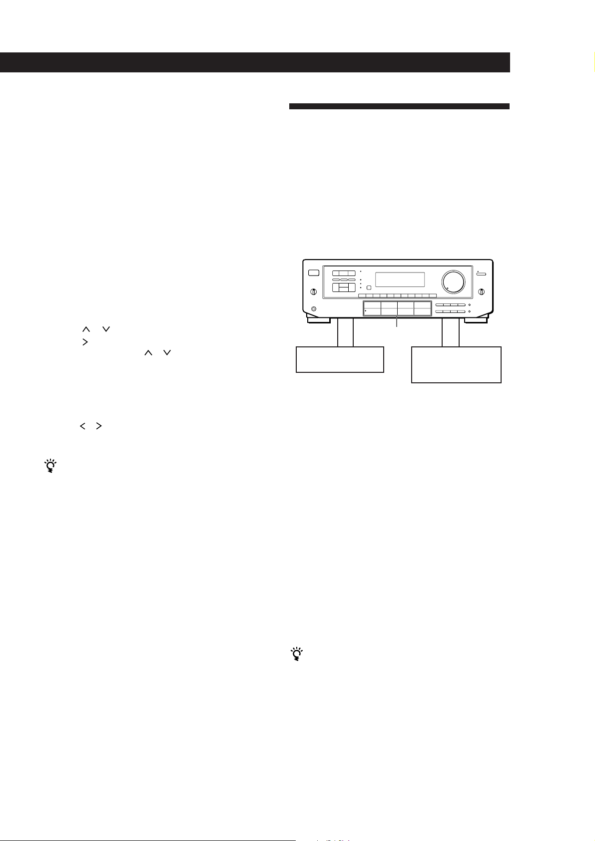
Hookup Overview
The receiver allows you to connect and control the
following audio/video components. Follow the
hookup procedures for the components that you want
to connect to the receiver on the pages specified. To
learn the locations and names of each jacks, see “Rear
Panel Descriptions” on page 26.
Antenna Hookups (5)
Speaker
System
Hookups (6, 7)
Front
speaker
(L)
TV/VCR Hookups (7, 8)
TV
VCR
LD player
AM/FM antenna
Front
speaker
Active
woofer
(R)
When to replace batteries
Under normal use, the batteries should last for about 6
months. When the remote no longer operates the
receiver, replace both batteries with new ones.
Notes
• Do not leave the remote in an extremely hot or humid
place.
• Do not use a new battery with an old one.
• Do not expose the remote sensor to direct sunlight or
lighting apparatuses. Doing so may cause a malfunction.
• If you don’t use the remote for an extended period of time,
remove the batteries to avoid possible damage from
battery leakage and corrosion.
Center
speaker
Rear
speaker
(R)
Rear
speaker
(L)
CD player
Tape deck
DAT/MD deck
Turntable
Audio Component
Hookups (5, 6)
Before you get started
• Turn off the power to all components before making
any connections.
• Do not connect the AC power cords until all of the
connections are completed.
• Be sure to make connections firmly to avoid hum
and noise.
• When connecting an audio/video cable, be sure to
match the color-coded pins to the appropriate jacks
on the components: Yellow (video) to Yellow; White
(left, audio) to White; and Red (right, audio) to Red.
EN
4
Page 5
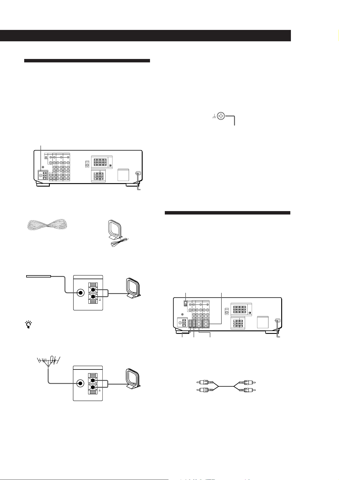
Antenna Hookups
Overview
This section describes how to connect AM and FM
antennas to the receiver. If you want to receive radio
broadcasts with the receiver, complete these
connections first, then go to the following pages.
For specific locations of the terminals, see the
illustration below.
ANTENNA
What antennas will I need?
• FM wire antenna
(supplied) (1)
• AM loop antenna
(supplied) (1)
Getting Started
Connecting a ground wire
To prevent hum, connect a ground wire (not supplied)
to the y ground terminal. If you’ve connected an
outdoor antenna, be sure to connect the ground for
lightning protection.
Receiver
.
to ground
Where do I go next?
If you want to connect other components, go on to the next
section. If you’re only planning to use the receiver to listen
to the radio, go to “Speaker System Hookups” on pages 6
and 7.
Audio Component Hookups
Hookups
FM wire antenna
After connecting
the wire antenna,
Receiver
ANTENNA
FM
75Ω
COAXIAL
keep it as horizontal
as possible.
If you have poor FM reception
Connect a 75-ohm coaxial cable (not supplied) to an FM
outdoor antenna.
FM outdoor antenna
Receiver
ANTENNA
FM
75Ω
COAXIAL
AM loop antenna
AM
AM
Overview
This section describes how to connect your audio
components to the receiver. If you want to use the
receiver as an amplifier, complete these connections.
For specific locations of the jacks, see the illustration
below.
S-LINK CTRL A1 jack TAPE
PHONO DAT/MD
What cords will I need?
Audio cords (not supplied) (1 for each CD player and
turntable; 2 for each tape deck, DAT deck, or MD deck)
White (L)
CD
White (L)
Red (R)Red (R)
(continued)
EN
5
Page 6
Getting Started
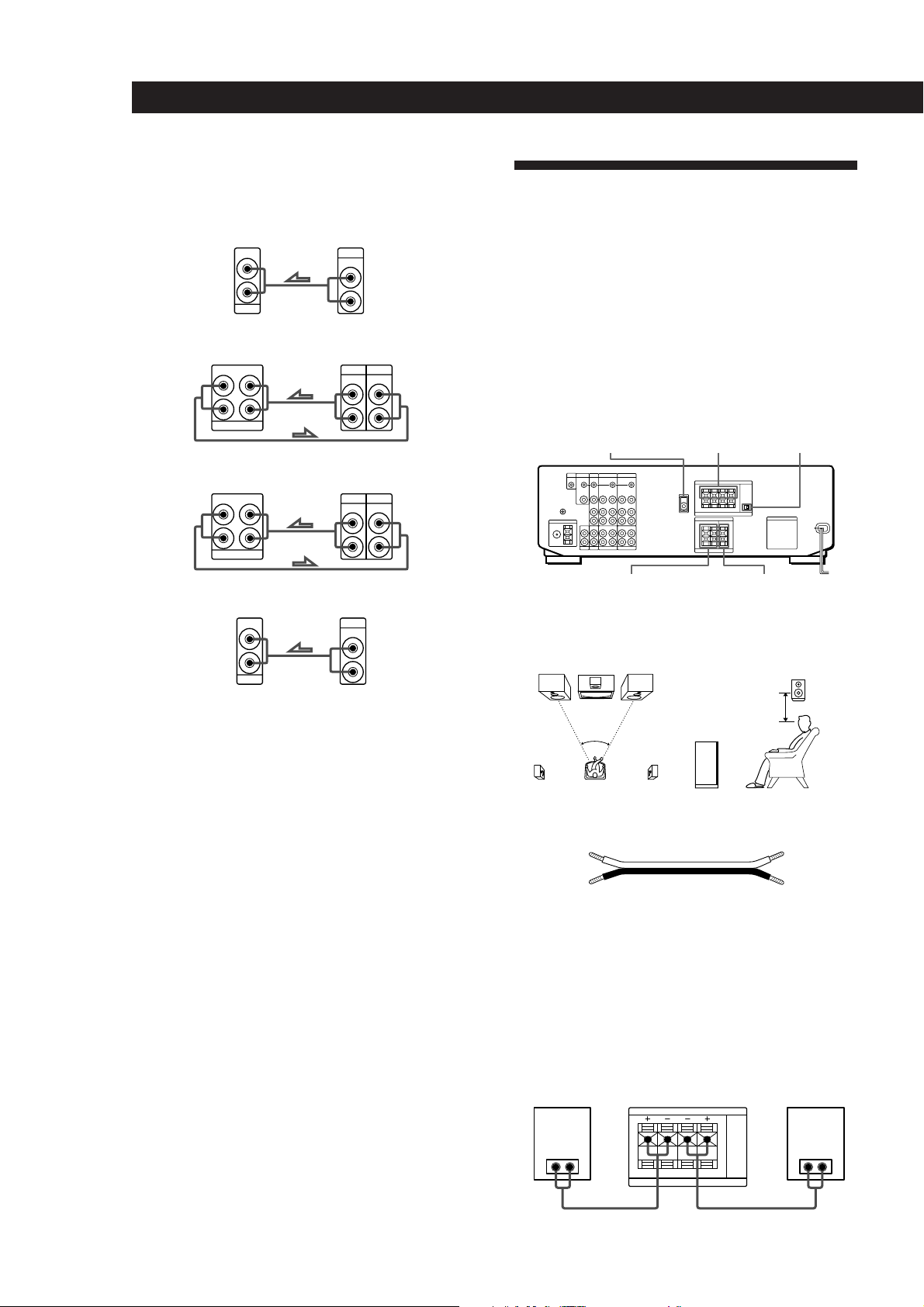
Hookups
The arrow ç indicates signal flow.
Speaker System Hookups
CD player
Receiver
IN
L
R
CD
CD player
OUTPUT
LINE
L
R
Tape deck
Tape deckReceiver
OUTPUT
L
R
TAPE MONITOR
INREC OUT
INPUT
LINELINE
L
R
DAT/MD
DAT/MDReceiver
OUTPUT
OUTPUT
LINE
INPUT
L
R
LINELINE
L
R
Turntable
INREC OUT
L
R
DAT/MD
Receiver Turntable
IN
L
R
PHONO
• If your turntable has an earth lead
To prevent hum, connect the earth lead to the y ground
terminal on the receiver.
Overview
This section describes how to connect your speakers to
the receiver. Although front (left and right) speakers
are required, center and rear speakers are optional.
Adding center and rear speakers will enhance the
surround effects. Connecting an active woofer will
increase bass response.
For specific locations of the terminals, see the
illustration below.
IMPEDANCE
FRONT SPEAKERS AMIX OUT
SURROUND
SPEAKERS REAR
For optimum surround sound effect, place your
speakers as shown below.
60 - 90 cm
45°
Front speaker
SELECTOR
SURROUND
SPEAKERS CENTER
Rear speaker
CONTROL A1 Hookups
What cords will I need?
• If you have a CONTROL A1 compatible Sony CD player
or tape deck
Use a CONTROL A1 cord (not supplied) to connect the
S-LINK CTRL A1 jack on the CD player or tape deck to the
S-LINK CTRL A1 jack on the receiver. Refer the separate
manual “CONTROL-A1 Control System” and the
Operating Instructions supplied with your CD player or
tape deck for details.
• If you have a Sony CD changer with a COMMAND
MODE selector
If the CD changer’s COMMAND MODE selector can be
switched between CD 1, CD 2, and CD 3, be sure to set the
command mode to “CD 1” and connect the changer to the
CD terminals on the receiver.
However, if you have a Sony CD changer with VIDEO
OUT terminals, set the command mode to “CD 2” and
connect the changer to the VIDEO 2 terminals on the
receiver.
Where do I go next?
Go on to the next section to connect the speakers.
EN
6
Speaker cord (not supplied) (1 for each speaker)
(+)
(–)
(+)
(–)
Twist the stripped ends of the cord about 15 mm. Be sure to
match the speaker cord to the appropriate terminal on the
components: + to + and – to –. If the cords are reversed, the
sound will be distorted and will lack bass.
Hookups
Front speakers
Front speaker
(R)
} ]} ]
Receiver
FRONT SPEAKERS
R L
AA
IMPEDANCE USE 4-16 Ω
Front speaker
(L)
Page 7
Getting Started
L
R
L
R
TV/DBS
OUTPUT
VIDEO
IN
AUDIO
IN
CTRL S
STATUS IN
VIDEO
AUDIO
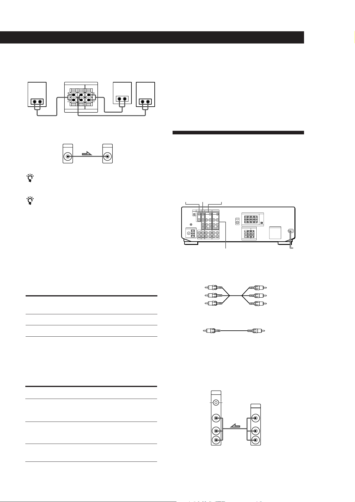
Rear and center speakers
Rear speaker
(R)
Receiver
SURROUND SPEAKERS
REAR LR CENTER
} ]} ]
LR
IMPEDANCE USE 8-16 Ω
Rear speaker
} ]
Active woofer
Receiver Active woofer
MIX
AUDIO
OUT
INPUT
If you have an additional front speaker system
Connect them to the FRONT SPEAKERS B terminals.
If your TV monitor uses separate speakers
You can connect one of them to the SURROUND
SPEAKER CENTER terminals for use with Dolby Pro
Logic Surround Sound (see page 18).
Where do I go next?
(L)Center speaker
To complete your system, go to “AC Hookups” on page 8. If
you want to connect video components to enjoy surround
sound when watching TV programs or video tapes, go on to
the next section.
TV/VCR Hookups
Overview
This section describes how to connect video
components to the receiver. For specific locations of the
jacks, see the illustration below.
TVMONITOR VIDEO 2
Selecting the impedance
Set the IMPEDANCE SELECTOR for the front speakers
as indicated in the table below. Check the instruction
manual of your speakers if you’re not sure of the
impedance. (This information is usually printed on a
label on the back of the speaker.)
if nominal impedance of
Set IMPEDANCE SELECTOR to
your speaker is
Between 4 and 8 ohms
8 ohms or higher
4 Ω
8 Ω
Selecting the speaker system
If you connect only one set of front speakers, set the
SPEAKERS selector on the front panel to A. If you
connect two sets of front speakers, see the following:
To drive
Speaker system A (connected
to the FRONT SPEAKERS A
terminals)
Set SPEAKERS selector to
A
VIDEO 1
What cables will I need?
• Audio/video cable (not supplied) (1 for each TV or LD
player; 2 for each VCR)
Yellow
White (L)
Red (R)
Yellow
White (L)
Red (R)
• Video cable (not supplied) (1 for a TV monitor)
Yellow
Yellow
Hookups
The arrow ç indicates signal flow.
TV or Digital Broadcasting System (DBS) tuner
Receiver TV
or
DBS tuner
Speaker system B (connected
B
to the FRONT SPEAKERS B
terminals)
Both speaker systems A and
A+B*
B (parallel connection)
*Do not use A+B with SOUND FIELD set to ON.
(continued)
EN
7
Page 8
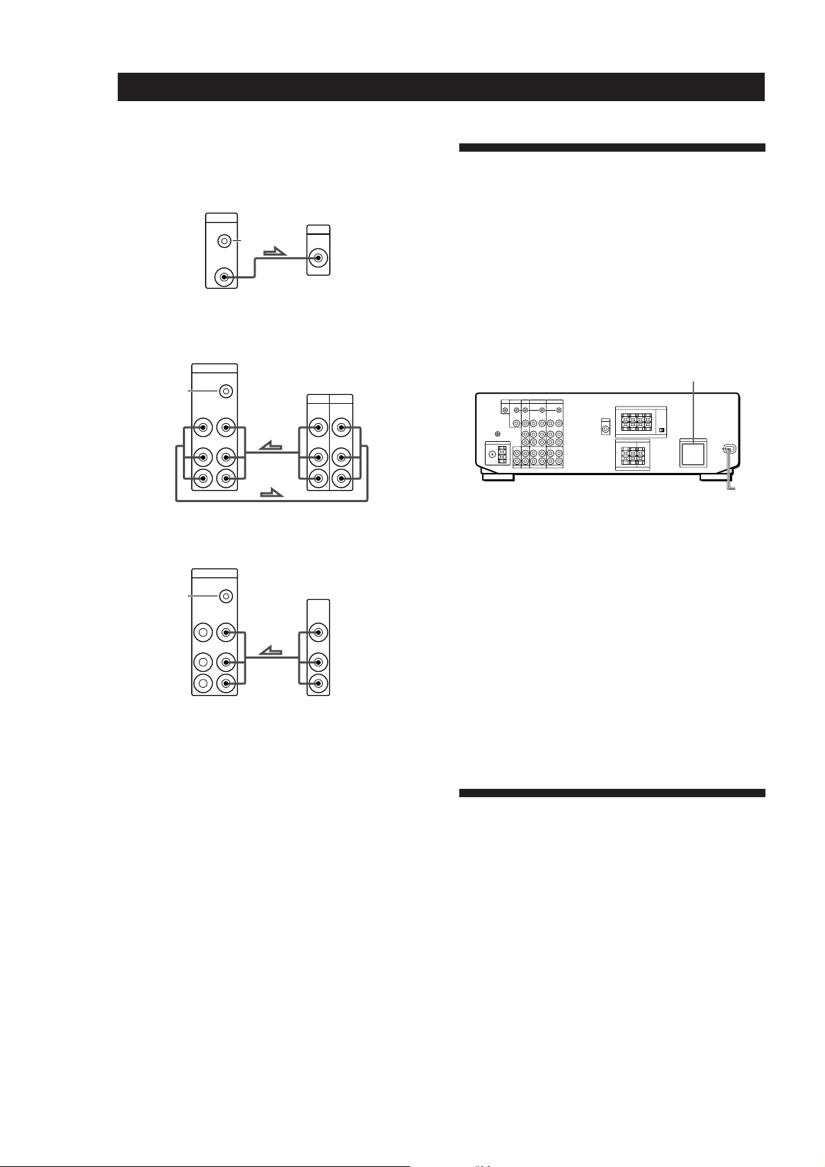
Getting Started
TV monitor
If you use a TV monitor, do not connect anything to the
TV/DBS VIDEO IN jack.
Receiver
MONITOR
CTRL S
IN
VIDEO
OUT
VCR (via the VIDEO 1 jacks)
If you have two VCRs connect the second one to the VIDEO
2 jacks.
Receiver
VIDEO 1
CTRL S
OUT
S-LINK
VIDEO
VIDEO
IN
OUT
AUDIO
AUDIO
IN
OUT
L
TV monitor
INPUT
VIDEO
VCR
OUTPUT
INPUT
VIDEO VIDEO
AUDIO AUDIO
L
AC Hookups
Connecting the AC power cord
Connect the AC power cord from this receiver and
from your audio/video components to a wall outlet.
If you connect other audio components to the
SWITCHED AC OUTLETs on the receiver, the receiver
can supply power to the connected components so you
can turn on/off whole system when you turn on/off
the receiver.
SWITCHED AC OUTLETs
R
R
LD player (via the VIDEO 2 jacks)
Receiver
VIDEO 2
CTRL S
OUT
S-LINK
VIDEO
VIDEO
IN
OUT
AUDIO
AUDIO
IN
OUT
L
R
LD
OUTPUT
VIDEO
AUDIO
L
R
• If you have a CONTROL S compatible Sony TV, DBS
tuner, monitor, VCR or LD player
Use a CONTROL S cord (supplied) to connect the S-LINK
CTRL S IN (for TV, DBS tuner, or monitor) or OUT (for
VCR or LD player) jack on the receiver to the appropriate
S-LINK jack on the respective component. Refer to the
Operating Instructions supplied with your TV, DBS tuner,
monitor, VCR, or LD player for details.
Where do I go next?
Go on to the next section to connect an AC plug and
complete your home theater system.
/
to a wall
outlet
Caution
Make sure that the power consumption of the component(s)
connected to the receiver’s AC outlet(s) does not exceed the
wattage stated on the rear panel. Do not connect highwattage electrical home appliances such as electric irons,
fans, or TVs to this outlet.
Where do I go next?
Before you use the␣ receiver, go to the next section to make
sure that all the controls are set to the appropriate positions.
Before You Use Your Receiver
Before you start using your receiver, make sure that
you have:
• Turned MASTER VOLUME to the leftmost
position (0).
• Selected the appropriate speaker system. (For
details, see “Selecting the speaker system” on
page 7.)
• Set BALANCE to the center position.
Turn on the receiver and check the following indicator.
• Press MUTING on the remote if MUTING appears
in the display.
EN
8
Page 9
Receiver Operations
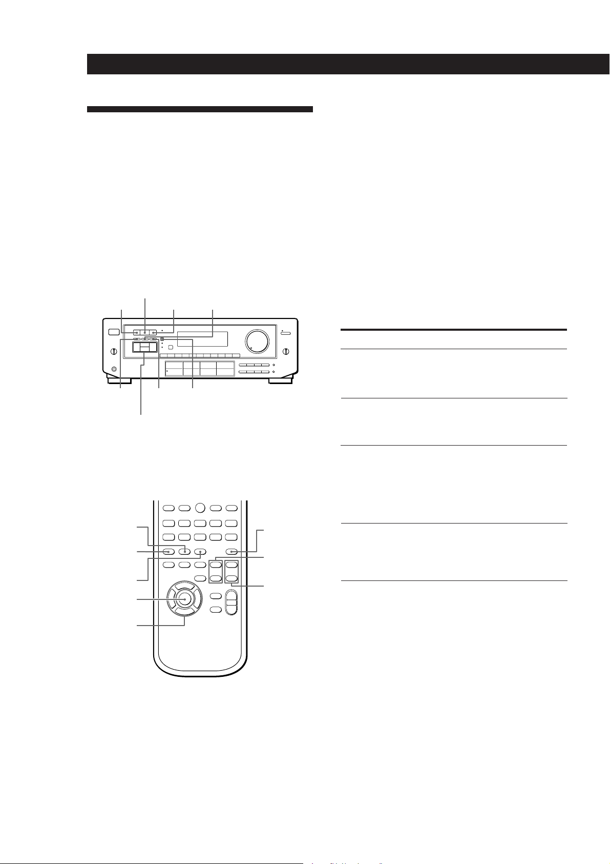
Selecting a Component
To listen to or watch a connected component, first
select the function on the receiver or with the remote.
Before you begin, make sure you have:
• Connected all components securely and correctly as
indicated on pages 5 to 8.
• Turned MASTER VOLUME to the leftmost position
(0) to avoid damaging your speakers.
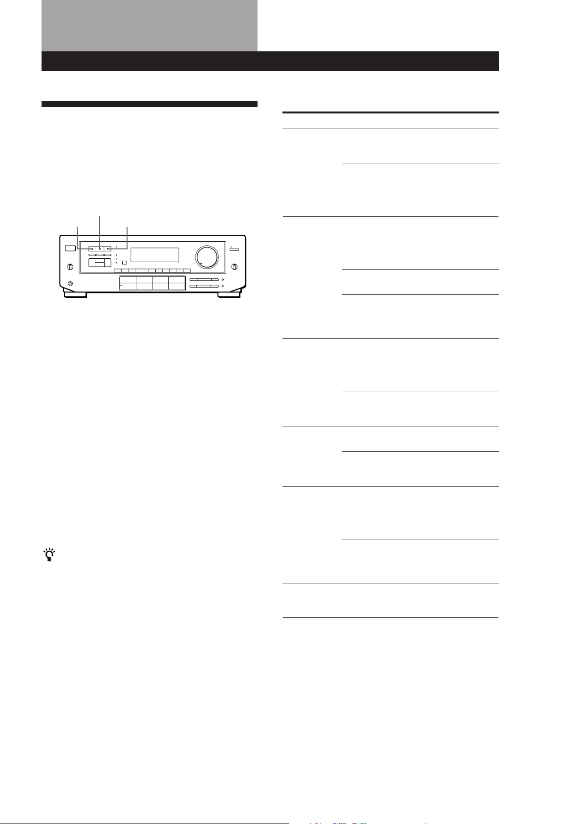
POWER MASTER VOLUME
Receiver Operations
When you listen with headphones
Connect the headphones to the PHONES jack and set
the SPEAKERS selector to OFF.
Watching video programs
When you watch TV or video programs, we
recommend you play audio portion through the
receiver instead of your TV’s speaker. This lets you
take advantage of the receiver’s surround sound
effects, like Dolby Surround, and lets you use the
receiver’s remote to control the audio.
Turn off the speakers on your TV before you start so
you can enjoy the surround sound from your receiver.
To watch TV programs, turn on both the TV and the
receiver and press the TV button on the receiver.
Function buttons
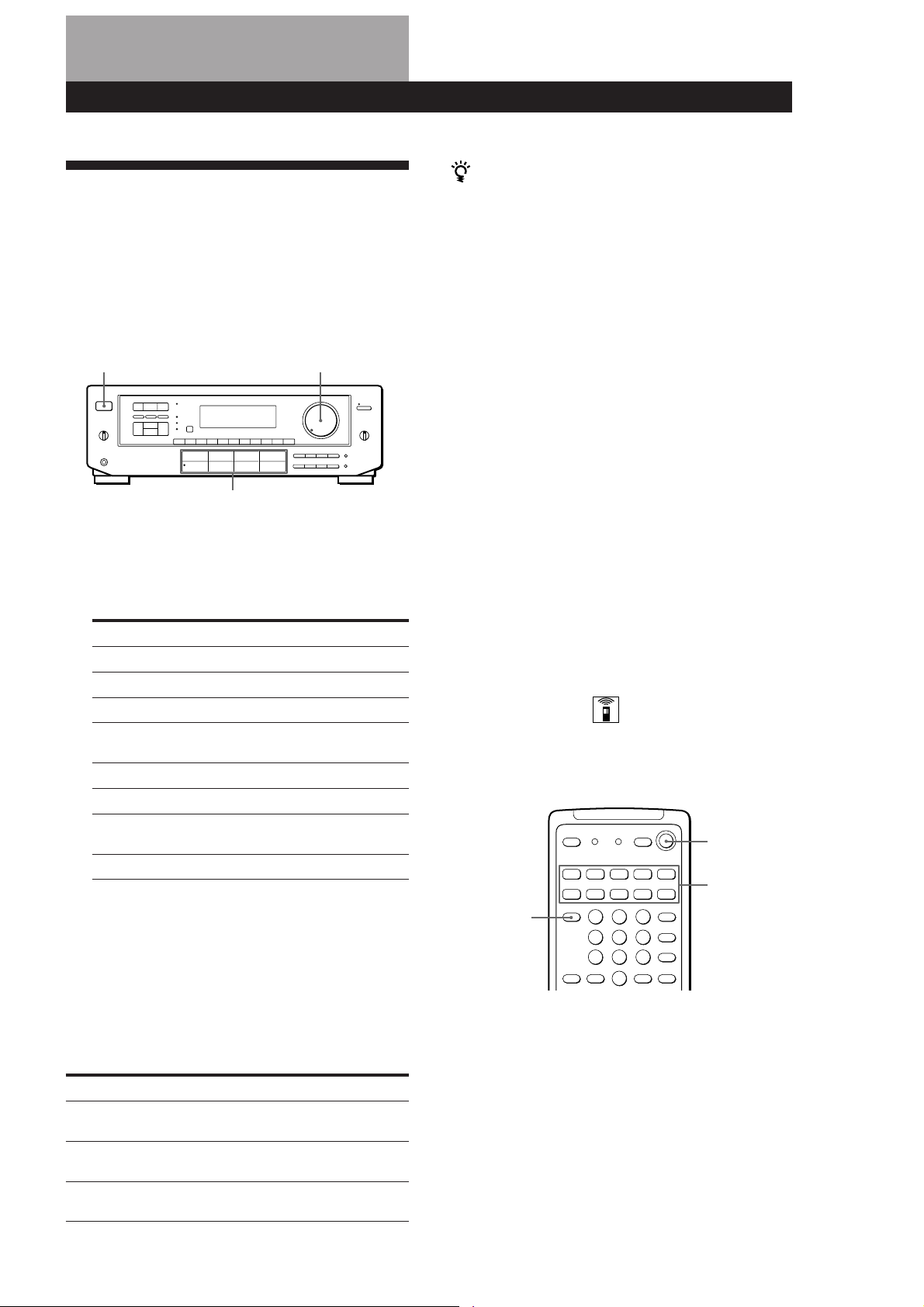
1 Press POWER to turn on the receiver.
2 Press a function button to select the component
you want to use:
To listen to or watch Press
Records PHONO
Radio programs TUNER
Compact Discs (CD) CD
Digital Audio Tapes (DAT) DAT/MD
or MiniDiscs (MD)
Audio tapes TAPE MONITOR
TV programs TV/DBS
Video tapes VIDEO 1 or
VIDEO 2
Laser discs VIDEO 2
3 Turn on the component, for example, a CD player,
and then start playing.
To tune in radio stations on this receiver, see
“Receiving Broadcasts” on page 10.
To watch videos or laser discs, do the following:
1 Press a function button to select the component
(for example, VIDEO 1).
2 Turn on the TV and set the TV’s video input to
match your video component.
3 Turn on the component (VCR or LD player), and
start playback.
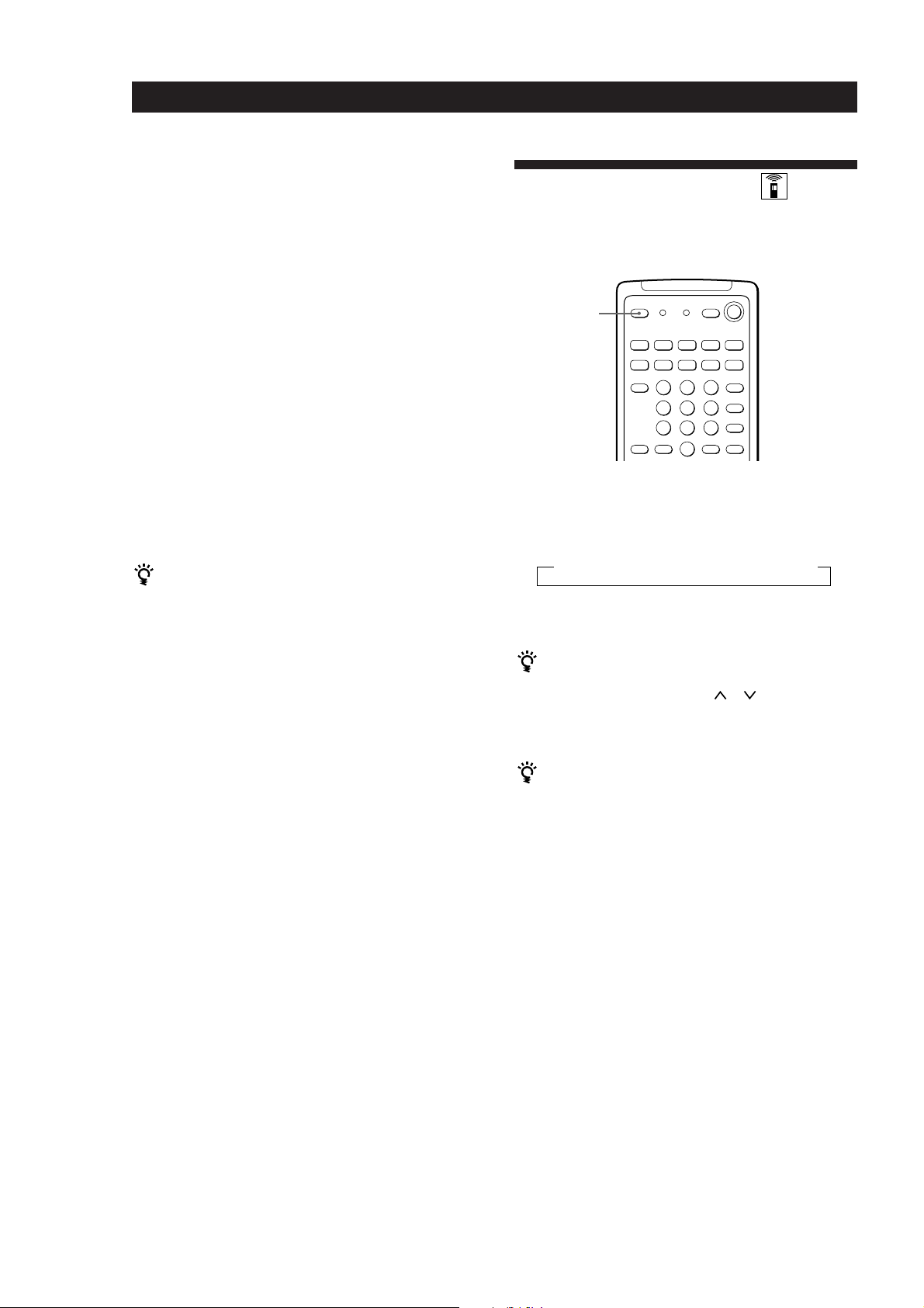
Using the remote
The remote lets you operate the receiver and the Sony
components that are connected to it.
SYSTEM
OFF
SYSTEM
CONTROL/
TV CONTROL
ON
FUNCTION
4 Turn MASTER VOLUME to adjust the volume.
To adjust the volume of the TV's speakers, use the
volume control on the TV.
To Do This
Mute the sound Press MUTING on the remote.
Reinforce the bass Press BASS BOOST to turn on
Adjust the balance Turn the BALANCE control left
Press again to restore the sound.
the BASS BOOST indicator
or right.
(continued)
EN
9
Page 10
Receiver Operations
1 0 2 5 0
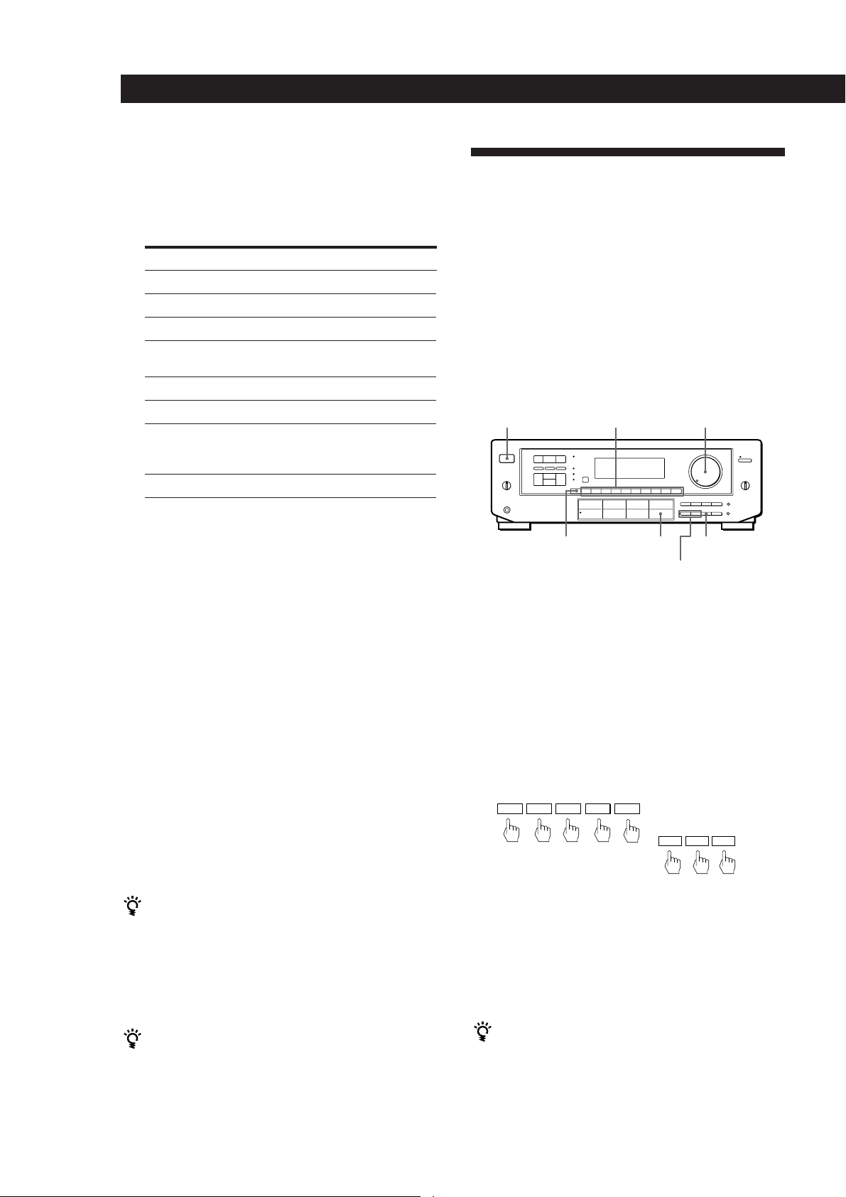
1 Press one of the SYSTEM CONTROL/FUNCTION
buttons to select the component you want to use.
The receiver and the selected component turn on.
The SYSTEM CONTROL/FUNCTION buttons on
the remote are factory-set as follows:
To listen to or watch Press
Records PHONO
Radio programs TUNER
Compact Discs (CD) CD
Digital Audio Tapes (DAT) DAT/MD
or MiniDiscs (MD)
Audio tapes TAPE
TV programs TV/DBS
Video tapes VIDEO 1 (VTR 1*),
VIDEO 2 (VTR 2*) or
VIDEO 3** (VTR 3*)
Laser discs LD**
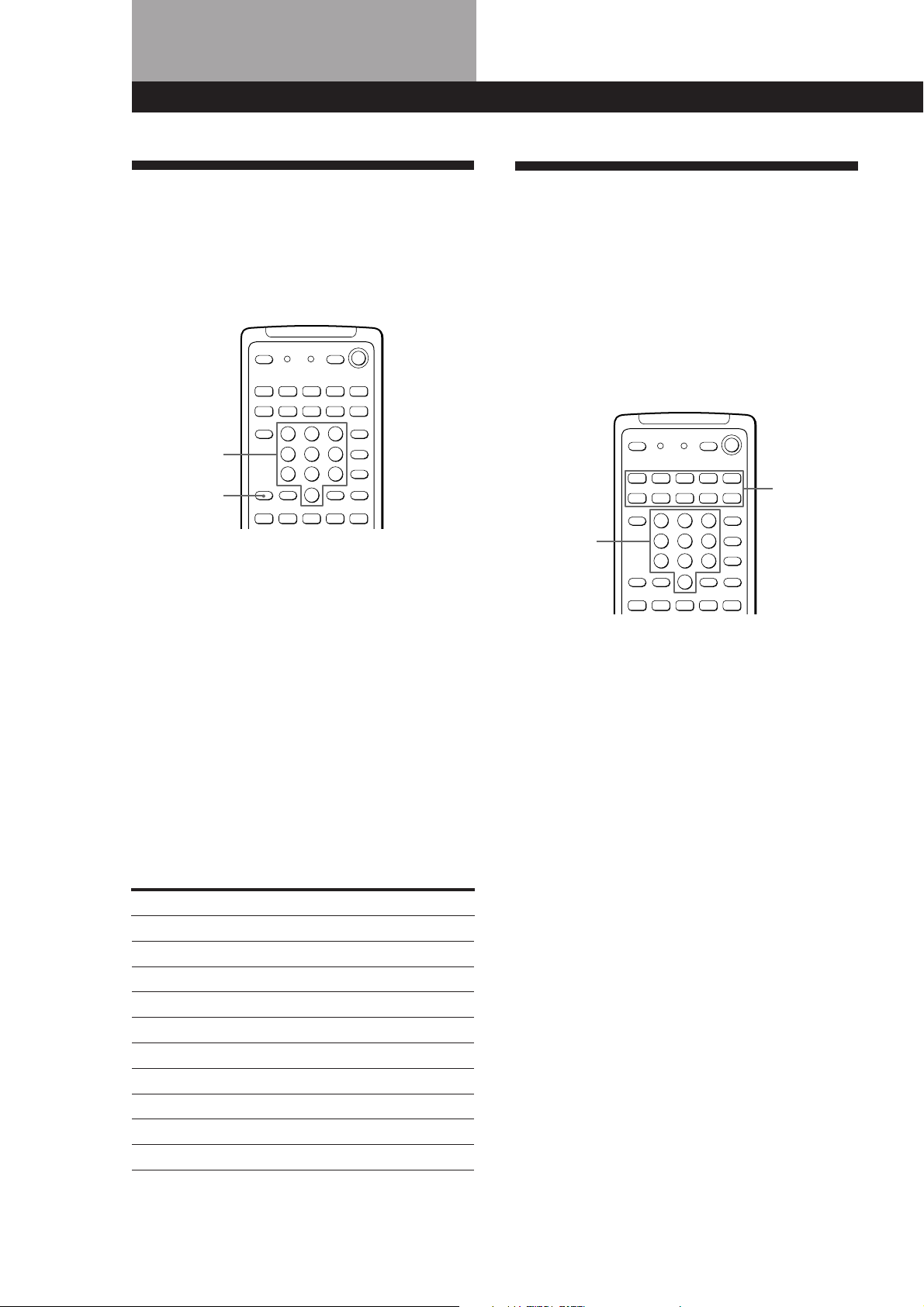
Receiving Broadcasts
This receiver lets you enter a station’s frequency
directly by using the numeric buttons (direct tuning). If
you don’t know the frequency of the station you want,
see “Receiving broadcasts by scanning stations
(automatic tuning)”.
Before you begin, make sure you have:
• Connected an FM/AM antenna to the receiver as
indicated on page 5.
• Selected the appropriate speaker system. (For details,
see “Selecting the speaker system” on page 7.)
POWER MASTER VOLUMENumeric buttons
* Sony VCRs are operated with a VTR 1, 2, or 3 setting
that correspond to Beta, 8mm and VHS, respectively.
** VIDEO 3 and LD set the remote to operate the
respective Sony video component but do not switch
the function of the receiver.
For example, to watch Sony LD player connected to
the VIDEO 2 terminals (as shown on page 8):
Press VIDEO 2 to switch the function, then press LD
to set the remote control to operate the LD player.
If you want to change the factory setting of a button
See page 20.
If the component does not turn on
Press the power switch on the component.
2 Start playing.
Refer to “Remote Button Descriptions” on page 27
for details.
To turn off the components
Press SYSTEM OFF. This will also turn off the video and
audio components connected to the SWITCHED AC
OUTLETs on the back of this unit at the same time.
If you use a Sony TV
When you press TV to watch a TV program, the TV
turns on and switches to the TV input. The TV also turns
on automatically and switches to the appropriate video
input when you press VIDEO 1 or VIDEO 2. If the TV
does not switch to the appropriate input automatically,
press TV/VIDEO on the remote.
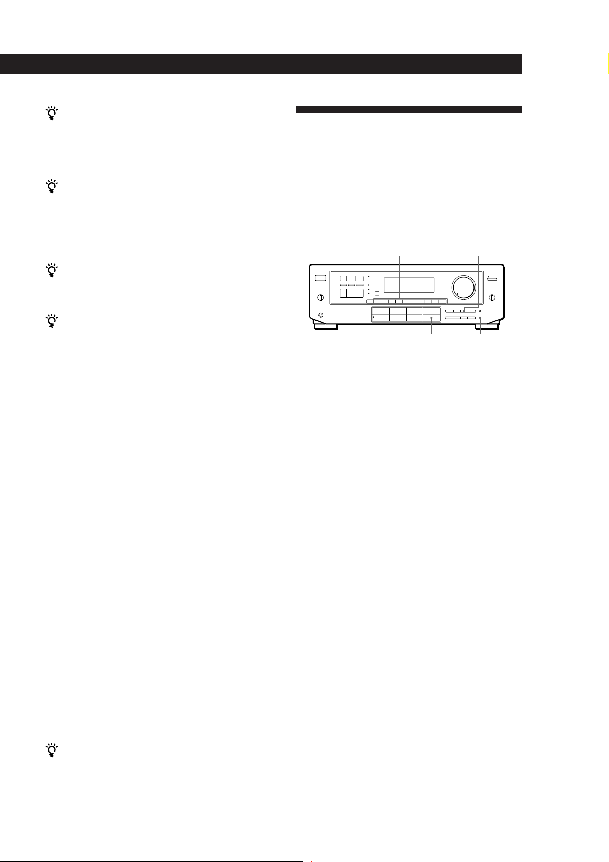
TUNERDIRECT
– INDEX SELECT +
FM/AM
TUNING/
1 Press POWER to turn on the receiver.
2 Press TUNER.
The last received station is tuned in.
3 Press FM/AM to select FM or AM stations.
4 Press DIRECT.
5 Press the numeric buttons to enter the frequency.
Example 1:FM 102.50 MHz Example 2:AM 1350kHz
(You don’t have to enter
the last “0.”)
1 3 5
6 When you tune in AM stations, adjust the
direction of the AM loop antenna for optimum
reception.
To receive other stations
Repeat Steps 3 to 5.
EN
10
Watching TV without the receiver (for Sony TVs only)
Press TV CONTROL ON to set the remote to operate TV
functions only (see “Remote Button Descriptions” on
page 27 for details). When you press this button, the TV
turns on and switches to the TV input. If the TV does
not automatically switch to the TV input, press TV/
VIDEO.
If the STEREO indicator remains off
Press FM MODE even when an FM stereo broadcast is
received.
Page 11
If an FM stereo program is distorted
The STEREO indicator flashes. Press FM MODE to
change to monaural (MONO). You will not have the
stereo effect but the distortion will be reduced. To
return to the auto stereo mode, press this button again.
If you cannot tune in a station and the entered
numbers are flashing
Make sure you’ve entered the right frequency. If not,
press DIRECT and reenter the frequency you want.
If the entered numbers still flash, the frequency is not
used in your area.
To watch FM simulcast TV programs
Make sure that you tune in the simulcast program on
both the TV (or VCR) and the receiver.
If you enter a frequency not covered by the tuning
interval
The entered value is automatically rounded up or down
to the closest covered value.
Tuning intervals for direct tuning are:
FM: 50 kHz intervals
AM: 10 kHz intervals (to change to 9 kHz intervals, see
page 23)
Receiving broadcasts by scanning stations
(automatic tuning)
If you don’t know the frequency of the radio station
you want, you can have the receiver scan all the
receivable stations to locate the one you want.
1 Press TUNER.
The last received station is tuned in.
Receiver Operations
Presetting Radio Stations
You’ll most likely want to preset the receiver with the
radio stations you listen to often so that you don’t have
to tune in the station every time. The receiver can store
a total of 30 FM or AM stations. You can store the
stations on preset numbers combining 3 characters (A,
B and C) and numbers (0-9). For example, you can
store a station as preset number A1, B6, or C9.
Numeric buttons SHIFT
TUNER MEMORY
1 Press TUNER.
The last received station is tuned in.
2 Tune in the station you want.
If you are not familiar with how to tune in a
station, see “Receiving Broadcasts” on the
previous page.
3 Press MEMORY.
“MEMORY” appears for a few seconds.
Do steps 4 and 5 before “MEMORY” goes out.
4 Press SHIFT to select a memory page (A, B or C).
Each time you press SHIFT, the letter “A”, “B” or
“C” appear in the display.
2 Press DISPLAY so that the frequency appears in
the display.
3 Press FM/AM to select FM or AM.
4 Press TUNING/INDEX SELECT + or –.
Press the + button for a higher station number;
press the – button for a lower one. When you tune
past either end of the band, the receiver
automatically jumps to the opposite end and
continues scanning in the same direction. Every
time a station is received, the receiver stops
scanning. To continue scanning, press the button
again.
If scanning stops too frequently (for FM band only)
Skip the stations with weak signals. Press LEVEL.
“HIGH” appears in the display and the receiver scans
only stations with strong signals.
5 Press the number you want to use (0 to 9).
If “MEMORY” goes out before you specify the preset
number, start again from step 3.
6 Repeat steps 2 to 5 to preset other stations.
To change a preset station
Preset a new station on the number you want to change.
Note
If the AC power cord is disconnected for about one week,
the preset stations will be cleared from the receiver’s
memory, and you will have to preset the stations again.
(continued)
11
EN
Page 12
Receiver Operations
Tuning preset stations (preset tuning)
You can tune directly to a preset station by entering its
preset number. If you don’t know which stations are
preset on which numbers, you can tune by scanning
the preset stations.
1 Press TUNER.
The last received station is tuned in.
2 Press SHIFT to select a memory page (A, B or C),
then press the number.
For example, select A and then press 7 to tune in
the station preset as A7.
You can tune by scanning the preset stations
Press TUNER and then DISPLAY so that the frequency
display appears. Then press PRESET TUNING + or – to
select the station you want. Each time you press the
buttons, the preset numbers change as follows:
nA1˜A2˜...˜A0˜B1˜B2˜...˜B0N
nC0˜...C2˜C1N
Indexing
You can index preset stations and then use the index
names to scan specific stations in the preset memory.
You can also use the index feature to label program
sources so that the receiver displays the names of the
components you connected, for example, “VHS”.
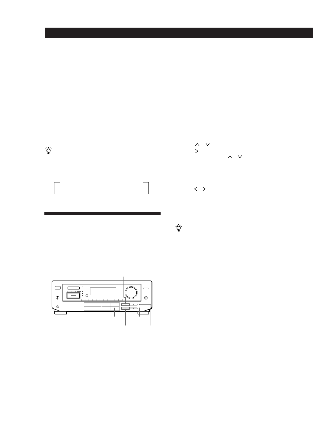
PRESET TUNING +/–DPC MODE
1 Press TUNER.
The last station you received is tuned in.
2 Tune in the preset station you want to create an
index for.
If you are not familiar with how to tune in preset
stations, see “Tuning preset stations (preset
tuning)” above.
3 Press DPC MODE repeatedly until the INDEX
indicator lights up.
4 Create a station index name by using the digital
processing control buttons as follows:
Press
press
To insert a space, press or until a blank space
appears in the display (the space is between “}” and
“!”).
The station index is stored automatically.
If you’ve made a mistake
Press or repeatedly until the character you want to
change flashes. Then select the right character.
or to select a character, and then
to move the cursor to the next position.
5 Repeat Steps 2 to 4 to assign index names to other
stations.
You can display either the index name or frequency
Each time you press DISPLAY, the display switches
between the frequency and the index name.
Scanning indexed stations (index tuning)
Once you select a station index, you can scan all the
stations with that station index.
12
EN
Digital
processing
control buttons
TUNER MEMORY
DISPLAYTUNING/
INDEX SELECT +/–
Indexing preset stations
You might find that too many preset stations make it
hard to find the station you want. This receiver
includes a feature that lets you group preset stations by
name (station index) using up to 8 characters.
For example, if you label all of your preset jazz stations
“JAZZ,” selecting “JAZZ” lets you skip other presets
and scan only the stations labeled “JAZZ.” Note that
you cannot assign more than one station index name to
each preset station.
1 Press TUNER.
The last station you received is tuned in.
2 Press DISPLAY so that the index mode appears in
the display.
The station index for the last station you received
appears in the display.
If “_ _ _ _ ” appears
The station does not have a station index.
3 Press TUNING/INDEX SELECT + or – to select
the station index you want to scan.
4 Press PRESET TUNING + or – to select the station
you want receive.
To select different station indexes
Press TUNING/INDEX SELECT + or – to select the one you
want, then press PRESET TUNING + or – to select a station.
Page 13
Indexing program sources
This feature is useful when, for example, you have
more than one VCR: you can label one VCR as “VHS”
and label the other as “8MM.” Then, you can have the
receiver display the index names so you can tell which
VCR you are using. This feature also comes in handy if
you connect a component to jacks designed for another
component (for example, connecting a second CD
player to the DAT/MD jacks).
1 Press the FUNCTION button you want to label.
2 Press DPC MODE repeatedly until the INDEX
indicator lights up.
3 Create a name by using the digital processing
control buttons as follows:
Press
press
To insert a space, press or until a blank space
appears in the display (the space is between “}” and
“!”).
The name you created is stored automatically.
or to select a character, and then
to move the cursor to the next position.
Receiver Operations
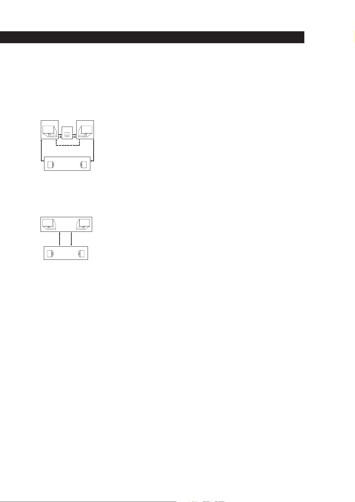
Recording
This receiver makes it easy to record to and from the
components connected to the receiver. You don’t have
to connect playback and recording components
directly: once you select a program source on the
receiver, you can record and edit as you normally
would using the controls on each component.
Before you begin, make sure you’ve connected all
components properly.
c
Function buttons
c
ç
Playback component
(program source)
ç: Audio signal flow
c: Video signal flow
ç
Recording component
(tape deck, DAT deck,
MD deck, VCR)
If you’ve made a mistake
Press or repeatedly until the character you want to
change flashes. Then select the right character.
You can display either the index or function name
Each time you press DISPLAY, the display switches
between the function name and the index name.
Recording on an audio tape or MiniDisc
You can record on a cassette tape, Digital Audio Tape
or MiniDisc using the receiver. See the instruction
manual of your cassette deck, DAT deck, or MD deck if
you need help.
1 Press one of the function buttons to select the
component to be recorded.
2 Set the component to be ready for playing.
For example, insert a CD into the CD player.
3 Insert a blank tape into the recording deck and
adjust the recording level, if necessary.
4 Start recording on the recording deck and then
start playing the component.
You can monitor the sound being recorded
If you connected a 3-head tape deck to the TAPE
MONITOR jacks, press TAPE MONITOR. The TAPE
MONITOR indicator lights up and you can hear the
sound being recorded.
Note
When you record on a DAT or MD connected to the DAT/
MD REC OUT jacks, sound adjustments do not effect the
recording.
(continued)
13
EN
Page 14
Receiver Operations
Recording on a video tape
You can record from a VCR, a TV, or an LD player
using the receiver. You can also add audio from a
variety of audio sources when editing a video tape. See
your VCR or LD player’s instruction manual if you
need help.
Using the Sleep Timer
You can set the receiver to turn off automatically at a
time you specify.
1 Press one of the function buttons to select the
program source to be recorded.
2 Set the component to be ready for playing.
For example, insert the laser disc you want to
record from into the LD player.
3 Insert a blank video tape into the VCR (VIDEO 1
or VIDEO 2) for recording.
4 Start recording on the recording VCR and then
start playing the video tape or laser disc you want
to record.
You can replace audio while copying a video tape or
laser disc
At the point you want to start adding different sound,
press another function button (for example, CD) and
start playback. The sound from the selected component
will be recorded over the original audio.
To resume recording the sound of the original playback
source, press the function button for that component.
SLEEP
Press SLEEP on the remote while the power is on.
Each time you press SLEEP, the time changes as shown
below.
n 2:00:00 n 1:30:00n 1:00:00 n 0:30:00 n OFF
The display dims after you specify the time.
You can freely specify the time
Press SLEEP first, then specify the time you want using
the digital processing control ( or ) buttons. The
sleep time changes in 1 minute intervals. You can
specify up to 5 hours.
You can check the time remaining before the
receiver turns off
Press SLEEP. The remaining time appears in the
display.
14
EN
Page 15
Using Surround Sound
Using Pre-programmed Sound
Fields
You can take advantage of surround sound simply by
selecting one of the pre-programmed sound fields
according to the program you want to play.
SOUND FIELD
ON/OFF
GENRE
1 Press SOUND FIELD ON/OFF to turn on the
sound field.
One of the indicators lights up in the display.
2 Press GENRE to select the type of sound field you
desire.
3 Press MODE to select the mode you desire from
the respective genre.
Select the appropriate sound field according to
the chart shown at right.
To play without surround effects
Select “Acoustic” from MUSIC 2. The surround effects are
defeated but you can still adjust the tone parameter (see
page 16).
To turn off the sound fields
Press SOUND FIELD ON/OFF.
You can find Dolby Surround-encoded software by
looking at the packaging
However, some videos and laser discs may use Dolby
Surround sound even if it's not indicated on the
package.
Note
Make sure to select both speakers (A+B) with the SPEAKERS
selector when you use two sets of speakers; otherwise, you
will not obtain the full surround effect.
MODE
Using Surround Sound
Sound Fields
GENRE MODE To
PRO LOGIC PRO LOGIC Decode programs
processed with Dolby
Surround.
ENHANCED Provide additional
output to the rear
speakers after
decoding the Dolby
Surround program
MOVIE SMALL THEATER Add the acoustic
reflections of a small
theater to decoded
Dolby Surround
signals.
LARGE THEATER Add the reflections of
a larger theater.
MONO THEATER Create a theater-like
environment from
movies with monaural
soundtracks.
MUSIC 1 SMALL HALL Reproduce the
acoustics of a small
rectangular concert
hall. Ideal for soft
acoustic sounds.
LARGE HALL Reproduce the
acoustics of a larger
hall.
MUSIC 2 KARAOKE Reduce the vocals of a
stereo music source.
ACOUSTIC Reproduce normal 2
channel stereo.
(No surround effects)
SPORTS ARENA Reproduce the feeling
of being in the front
row of a large concert
arena. Great for Rock
and Roll.
STADIUM Reproduce the feeling
of a large open-air
stadium. Great for
electric sounds.
GAME – Obtain maximum
audio impact from
video game software.
15
EN
Page 16
Using Surround Sound
Taking Advantage of the
Sound Fields
How can you customize the sound fields?
Each sound field is composed of sound parameters —
variables of sound that create sound image. You can
customize the sound fields by adjusting some of the
sound parameters to best suit your listening situation.
See the following chart for the adjustable sound
parameters.
Before you get started
To take advantage of Dolby Pro Logic Surround sound,
go to “Getting the Most Out of Dolby Pro Logic
Surround Sound” on page 18. This section describes
how to adjust the levels of your speaker system and
customize the DOLBY SUR sound field.
Customizing Sound Fields
Once you customize the sound fields, they are stored in
memory unless the receiver is unplugged for about 1
week.
The adjustable parameters for each sound field are
shown on the charts below.
GENRE
PRO LOGIC
MOVIE
MUSIC 1
MUSIC 2
SPORTS
GAME
MODE
PRO LOGIC
ENHANCED
SMALL THEATER
LARGE THEATER
MONO MOVIE
SMALL HALL
LARGE HALL
KARAOKE
ACOUSTIC
ARENA
STADIUM
GAME
TONE
EFFECT
REAR
CENTER
DELAY
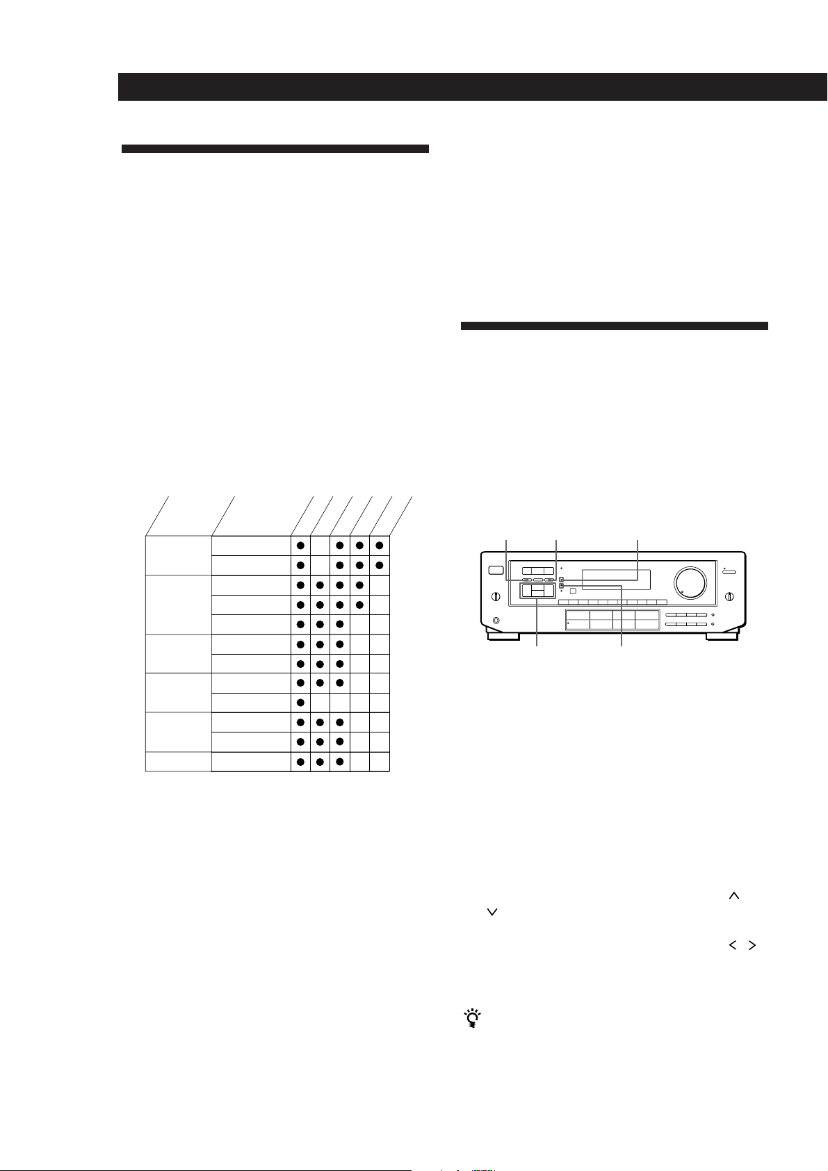
You can customize the sound fields by adjusting the
tone (bass or treble) and surround sound parameters
while listening to a program source. The adjusted
parameters are stored in memory automatically and
you can use your custom sound fields just as you
would use the pre-programmed ones. Before you start,
select the sound field you want to customize and start
playing a program.
TONE ON/OFF
Digital processing
control buttons
DPC MODE
SUR indicator
TONE indicator
Adjusting the tone parameter
Adjust the tone (bass or treble) of the front, center and
rear speakers for optimum sound. You can adjust the
tone of all sounds fields, including Dolby Surround.
16
EN
Note
The EFFECT parameter allows you to adjust the overall
presence of the sound field.
1 Press TONE ON/OFF so that TONE ON appears
in the display.
2 Press DPC MODE repeatedly until the TONE
indicator lights up.
3 Use the digital processing control buttons ( /
) to select BASS or TREBLE.
4 Use the digital processing control buttons ( / )
to adjust the tone level.
The adjusted tone level is stored automatically.
You can turn off the tone adjustments without
erasing them
The tone adjustments and on/off setting are stored in
each sound field. Press TONE ON/OFF to turn the tone
parameter off or on.
Page 17

Adjusting surround sound parameters
Change the surround parameters to fit your listening
situation. Refer to the chart on the previous page for
parameters you can adjust in each sound field.
To adjust the parameters of the DOLBY SUR sound
field, see “Getting the Most Out of Dolby Pro Logic
Surround Sound” on page 18.
1 Press DPC MODE repeatedly until the SUR
indicator lights up.
2 Use the digital processing control buttons ( /
) to select the parameter you want.
3 Use the digital processing control buttons ( / )
to adjust the level of the parameter.
The adjusted parameters are stored automatically.
Note
If you make new adjustments to a sound field, the previous
settings are replaced by the new ones.
Using Surround Sound
Resetting customized sound fields to the
factory settings
If the power is on, press POWER to turn off the
1
power.
2 Hold down SOUND FIELD ON/OFF and press
POWER.
“SURR CLEAR!” appears in the display and all
the sound fields are reset at once.
17
EN
Page 18
Using Surround Sound
Getting the Most Out of Dolby
Pro Logic Surround Sound
To obtain the best possible Dolby Pro Logic Surround
sound, first select the center mode according to your
speaker system. Then, adjust the sound parameters of
the PRO LOGIC sound field.
Note that you must have at least one additional pair of
speakers and/or one center speaker to do the following
adjustments.
Selecting the center mode
The receiver offers you four center modes:
PHANTOM, 3 CHANNEL LOGIC, NORMAL, and
WIDE. Each mode is designed for a different speaker
configuration. Select the mode that best suits your
speaker system configuration.
1 Press SOUND FIELD ON/OFF to turn on the
sound fields.
2 Press GENRE to select the PRO LOGIC sound
field.
SOUND FIELD
GENRE MODE
TONE
ON/OFF
Digital processing
control buttons
Remote
GENRE
SOUND FIELD
ON/OFF
MODE
DPC MODE
ON/OFF
DPC
MODE
CENTER MODE
SUR indicator
0)=+
9(p P r
TEST TONE
REAR
LEVEL (+/–)
CENTER
LEVEL (+/–)
3 Press CENTER MODE repeatedly until the center
mode you want appears in the display. Select the
center mode by referring to the following chart.
If you have
Front and rear
speakers, no
center speaker
Front and center
speakers, no rear
speaker
Front and rear
speakers, and a
small center
speaker
Front and rear
speakers, and a
center speaker
equivalent to your
front speakers
Select
PHANTOM
3 CH LOGIC
(3 Channel
Logic)
NORMAL
WIDE
So that
The sound of the
center channel is
output from the front
speakers.
The sound of the rear
channel is output
from the front
speakers.
The bass sound of the
center channel is
output from the front
speakers (because a
small speaker cannot
produce enough
bass).
For “complete”
Dolby Pro Logic
Surround sound.
18
DIGITAL
PROCESSING
CONTROL
EN
Page 19

Using Surround Sound
Adjusting the speaker volume
The test tone feature lets you set the volume of your
speakers to the same level. (If all of your speakers have
equal performance, you don’t have to adjust the
speaker volume.)
Using the controls on the remote lets you adjust the
volume level from your listening position.
1 Press TEST TONE on the remote.
You will hear the test tone from each speaker
sequentially.
2 Adjust the volume levels so that you hear the test
tone from each speaker at the same volume level
when you are in your listening position:
• To adjust the volume between the front right
and front left speakers, use the BALANCE
control on the front of the main unit.
• To adjust the level of center speaker, press
CENTER LEVEL + or – on the remote.
• To adjust the level of rear speakers, press
REAR LEVEL + or – on the remote.
Adjusting the tone
You can adjust the tone of the speakers.
Follow the procedure described in “Adjusting the tone
parameter” an page 16..
3 Press TEST TONE on the remote to turn off the
test tone.
You can adjust all speakers at one time
Adjust MASTER VOLUME
Adjusting the delay time
You can make the surround sound more effective by
delaying the output from the rear speakers (delay
time). You can adjust the delay time in 5 ms steps
within the range of 15 to 30 ms. For example, if you’ve
placed the rear speakers in a large room or apart from
your listening position, set the delay time shorter.
1 Start playing a program source encoded with
Dolby surround sound.
2 Press DPC MODE until the SUR indicator lights
up.
3 Use the digital processing control buttons ( /
) to select the delay time.
The current delay time appears in the display.
4 Use the digital processing control buttons ( / )
to adjust the delay time.
19
EN
Page 20
Advanced Remote Operations
0)=+
Operating One Component
While Using Another
(background operation)
You can temporality operate other components while
listening to or watching a program.
Numeric
buttons
BACKGROUND
1 Hold down BACKGROUND.
2 Press both the corresponding numeric button of
the component you’re going to use (see the table
below) and one of the following buttons at the
same time; VISUAL POWER, TV/VIDEO, CH
PRESET +/–, ANT TV/VTR, D.SKIP, (, 9, p,
0/), =/+, P, r.
0)=+
Changing the Factory Setting
of a FUNCTION Button
If the factory settings of the FUNCTION buttons (page
10) don’t match your system components, you can
change them. For example, if you connect a Sony LD
player to the VIDEO 2 jacks, you can assign the VIDEO
2 button to set the remote to control the LD player.
Note that the settings of the TUNER and PHONO
buttons cannot be changed.
SYSTEM
CONTROL/
FUNCTION
Numeric
buttons
1 Holding down the SYSTEM CONTROL/
FUNCTION button whose function you want to
change (VIDEO 2, for example).
20
EN
Example:To start recording on a tape deck while
listening to a CD
While holding down BACKGROUND,
press 4 (or 5) and press r + ( at the
same time.
The numeric buttons are assigned to select the
functions as follows:
Numeric button Operates
1 CD player
2 DAT deck
3 MD deck
4 Tape deck A
5 Tape deck B
6 LD player
7 VCR (remote control mode VTR 1*)
8 VCR (remote control mode VTR 2*)
9 VCR (remote control mode VTR 3*)
0TV
* Sony VCRs are operated with a VTR 1, 2 or 3 setting.
These correspond to Beta, 8mm and VHS respectively.
2 Press the corresponding numeric button of the
component you want to assign to the SYSTEM
CONTROL/FUNCTION button (6 - LD player,
for example).
For the numeric buttons, see the table in
“Operating One Component While Using
Another.”
Now you can use the VIDEO 2 button to control
your Sony LD player.
To reset the setting to the factory setting
Repeat the above procedure.
Page 21
Programming the Remote
Advanced Remote Operations
If the LEARN indicator flashes rapidly
You cannot use the button you’ve pressed.
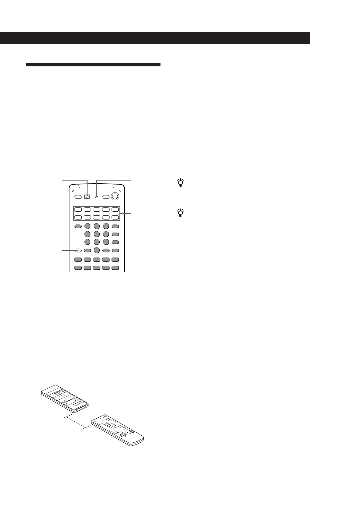
The remote can control non-Sony components by
“learning” the control signals from their remotes. Once
this remote learns the other components signals, you
can use these components as part of your system.
Additionally, if you have any Sony components that
fail to operate with this remote, use this programming
function. This remote can “learn” signals only from
other infrared wireless remotes. Before you program
signals, make sure that the two remotes:
• Face straight at each other (see Step 3 below)
• Are placed at a distance of about 5 cm
• Are not moved during programming
LEARN
indicator
BACKGROUND
0)=+
9(p P r
LEARN
SYSTEM
CONTROL/
FUNCTION
1 Press the SYSTEM CONTROL/FUNCTION
button of the component you want to program.
For example, if you want to program a CD
player’s remote, press CD.
2 Press LEARN to turn on the LEARN indicator.
3 Press the button on this unit’s remote that is to
“learn” the signal from the other remote.
The LEARN indicator flashes slowly.
Use only the shaded buttons shown above (see
“Remote Button Descriptions” on page 27 for the
buttons you can use to operate each component).
Other remote
4 On the other remote, select the function that the
receiver’s remote is to “learn” and hold down its
button until the LEARN indicator lights steadily.
5 Repeat Steps 3 and 4 to program other buttons.
Note that each button can only “learn” one signal
from another remote.
6 Press LEARN.
After the LEARN indicator turns off, you can
control the other component with the
programmed buttons.
When you program the recording signal
While holding down the r button on the receiver’s
remote and press the record button on the other remote.
If you cannot successfully program signals, check the
following:
• If the LEARN indicator does not light up at all, the
batteries are weak. Replace both batteries.
• If the LEARN indicator does not flash or light up in
Step 3 or 4, there is interference. Clear the signal as
described in “Clearing the programmed signal”
below and program again from the beginning.
• The two remotes are placed too far apart. Make sure
they are only 5cm apart.
• If you don’t proceed to the following steps within
about 1 minute during Steps 2 and 3, the remote
automatically exits learning mode. Start again from
Step 2.
• If the memory in the remote has become full, (If you
program signals of Sony components, you can store
about 60 signals.) you can program a new signal on a
previously programmed button, but the new signal
will replace the previously programmed one.
Notes
• You cannot turn on programmed components by pressing
a SYSTEM CONTROL/FUNCTION button. You have to
turn on the component's power switch.
• Do not program remote signals of air conditioners or other
household appliances.
About 5 cm
Receiver’s remote
Clearing the programmed signal
To clear the programmed signals, do the following.
The button’s functions are reset to the factory-preset.
1 Press LEARN to turn on the LEARN indicator.
2 While holding down BACKGROUND, hold down
the button to be cleared until the LEARN
indicator turns off.
21
EN
Page 22

Additional Information
Additional Information
Troubleshooting
If you experience any of the following difficulties while
using the receiver, use this troubleshooting guide to
help you remedy the problem. Should any problem
persist, consult your nearest Sony dealer.
There’s no sound or only a very low-level sound is heard.
/ Check that the speakers and components are
connected securely.
/ Make sure you select the correct component
on the receiver.
/ Make sure you set the SPEAKERS selector
correctly.
/ Press MUTING on the remote if MUTING is
shown in the display.
/ The protective device on the receiver has been
activated because of a short circuit.
(“PROTECTOR” flashes.) Turn off the
receiver, eliminate the short-circuit problem
and turn on the power again.
The left and right sounds are unbalanced or reversed.
/ Check that the speakers and components are
connected correctly and securely.
/ Adjust the BALANCE control.
No sound or only a very low-level sound is heard from
the rear speakers.
/ Turn on the sound field function.
/ Select the appropriate center mode
(see page 18).
/ Adjust the speaker volume appropriately
(see page 19).
/ Make sure you turned on the sound field
function.
Radio stations cannot be tuned in.
/ Check that the antennas are connected
securely. Adjust the antennas and connect an
external antenna if necessary.
/ The signal strength of the stations is too weak
(when you tune in with automatic tuning).
Use direct tuning.
/ Make sure you set the tuning interval
correctly (when you tune in AM stations with
automatic tuning) (see pages 11 and 23).
/ No stations have been preset or the preset
stations have been cleared (when you tune in
with scanning preset stations). Preset the
stations (see page 11).
/ Make sure to set the display mode to
“NORMAL MODE” (when you tune with
automatic tuning).
22
EN
Severe hum or noise is heard.
/ Check that the speakers and components are
connected securely.
/ Check that the connecting cords are away
from a transformer or motor, and at least 3
meters away from a TV set or fluorescent
light.
/ Place your TV away from the audio
components.
/ Make sure you connect a ground wire to the
antenna ground terminal.
/ The plugs and jacks are dirty. Wipe them
with a cloth slightly moistened with alcohol.
No sound is heard from the center speaker.
/ Select a PRO LOGIC or MOVIE (except Mono
movie) sound field (see page 15).
/ Select the appropriate center mode
(see page 18).
/ Adjust the speaker volume appropriately
(see page 19).
Recording cannot be made.
/ Check that the components are connected
correctly.
/ Select the source component with the
function buttons.
Surround effect cannot be obtained.
/ Turn on the sound field function.
/ Make sure that the SPEAKERS selector is set
to A+B when you use two sets of front
speakers.
No picture or an unclear picture is seen on the TV screen.
/ Select the appropriate function on the
receiver.
/ Set your TV to the appropriate input mode
(press TV/VIDEO on the remote for Sony
TVs).
/ Place your TV away from the audio
components.
The remote does not function.
/ Point the remote at the remote sensor g on
the receiver.
/ Remove the obstacles in the path of the
remote and the receiver.
/ Replace both batteries in the remote with new
ones if they are weak.
/ Make sure you select the correct function on
the remote.
/ Pressing TV CONTROL ON sets the remote
to operate the TV only. In this case, press one
of the SYSTEM CONTROL/FUNCTION
buttons before operating the receiver (etc.).
Page 23

Additional information
Additional Information
Specifications
Audio power specifications
Amplifier section
POWER OUTPUT
Stereo mode
Surround mode
Front
Center (only in
the DOLBY SUR
and THEATER
modes)
Rear
Dynamic power
output
Harmonic
distortion at
rated output
Frequency
response
Inputs
Sensitivity
PHONO
(MM)
CD
TAPE,
DAT/MD,
VIDEO 1,
2, TV
8 ohms 20 Hz - 20 kHz,
120 W + 120 W
8 ohms at 1 kHz,
THD 0.8 %
120 W/ch
120 W
50 W/ch
160 W + 160 W, 8 ohms
225 W + 225 W, 4 ohms
Less than 0.3 %
PHONO: RIAA
equalization curve
±0.5 dB
CD, TAPE, DAT/MD,
VIDEO 1, 2:
10 Hz - 50 kHz dB
Impedance
2.5 mV
kilohms
200 mV
150 mV
kilohms
50
50
+0
–1
S/N
(weighting
network,
input level)
75 dB**
(A, 2.5 mV)
82 dB**
(A, 250 mV)
** ‘78 IHF
Outputs
Muting
BASS BOOST
TONE
FM tuner section
Tuning range
Antenna
terminals
Sensitivity
Usable sensitivity
S/N
Harmonic
distortion at
1 kHz
Separation
Frequency
response
Selectivity
AM tuner section
Tuning range
Antenna
Usable sensitivity
REC OUT VIDEO 1, 2
(AUDIO) OUT:
Voltage 150 mV,
Impedance 10 kilohms
MIX OUT
Voltage: 2 V
Impedance: 1 kilohms
PHONES: Accepts low
and high impedance
headphones
– 20 dB
+10 dB at 70 Hz
±8 dB at 100 Hz and
10 kHz
87.5 - 108.0 MHz
75 ohms, unbalanced
Mono: 18.3 dBf, 4.5 µV
Stereo: 38.3 dBf, 45 µV
11.2 dBf, 2 µV (IHF)
Mono: 76 dB
Stereo: 70 dB
Mono: 0.3 %
Stereo: 0.5 %
45 dB at 1 kHz
30 Hz - 15 kHz dB
60 dB at 400 kHz
With 10 kHz interval*:
530 - 1710 kHz
With 9 kHz interval:
531 - 1710 kHz
Loop antenna
50 dB/m (at 1,000 kHz or
999 kHz)
+0.5
–2
S/N
Harmonic
distortion
Selectivity
*
You can change the AM tuning interval to 9
kHz. After tuning in any AM station, turn
off the receiver. Hold down the PRESET
TUNING + button and press the POWER
button. All preset stations will be erased
when you change the interval. To reset the
interval to 10 kHz, repeat the procedure.
54 dB (at 50 mV/m)
0.5 % (50 mV/m, 400 Hz)
At 9 kHz: 35 dB
At 10 kHz: 40 dB
Video section
Inputs
Outputs
VIDEO 1, 2, TV:
1 Vp-p 75 ohms
VIDEO 1, 2, MONITOR:
1 Vp-p 75 ohms
General
System
Power
requirements
Power
consumption
AC outlets
Dimensions
Mass (Approx.)
Supplied
accessories
Design and specifications are subject to
change without notice.
Tuner section: PLL
quartz-locked digital
synthesizer system
Preamplifier section: Low-
noise NF type equalizer
Power amplifier section:
Pure-complimentary SEPP
120 V AC, 60 Hz
230 W
2 switched, total 120 W
430 x 157 x 355 mm
1
(17 x 6
/4 x 14 inches)
10.0 kg (22 lb 1 oz)
FM wire antenna (1)
AM loop antenna (1)
Remote commander
(remote) (1)
Size AA (R6) batteries (2)
Audio/Video cable (1)
Control S cord (1)
23
EN
Page 24
Additional Information
Glossary
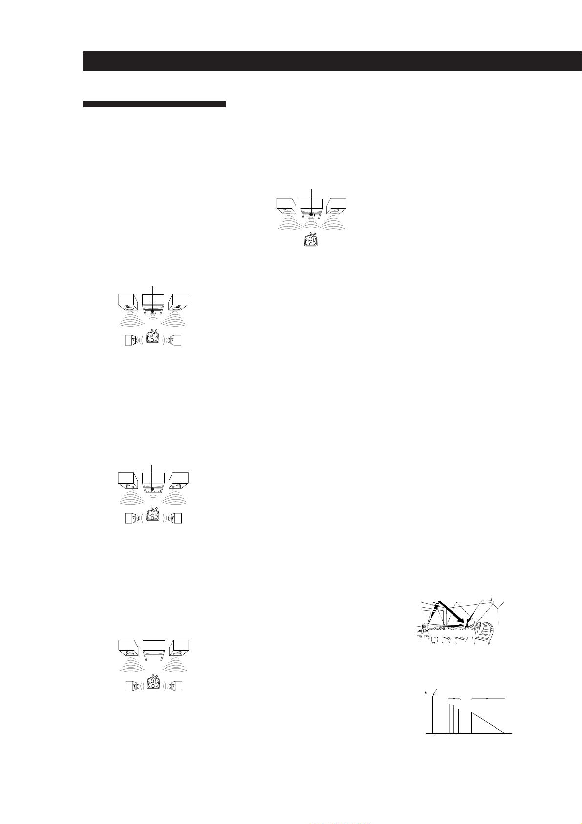
Center mode
Setting of speakers to enhance Dolby Pro
Logic Surround mode. To obtain the best
possible surround sound, select one of the
following four center modes according to
your speaker system.
• NORMAL mode
Select NORMAL mode if you have front
and rear speakers and a small center
speaker. Since a small speaker cannot
produce enough bass, the bass sound of
the center channel is output from the front
speakers.
Front
speaker (L)
speaker (L)
Center
speaker
Rear
• WIDE mode
Select WIDE mode if you have front and
rear speakers and a large center speaker.
With the WIDE mode, you can take full
advantage of Dolby Surround sound.
Front
speaker (L)
Center
speaker
Rear
speaker (L)
• PHANTOM mode
Select PHANTOM mode if you have front
and rear speakers but no center speaker.
The sound of the center channel is output
from the front speakers.
Front
speaker (L)
Rear
speaker (L)
Front
speaker (R)
Rear
speaker (R)
Front
speaker (R)
Rear
speaker (R)
Front
speaker (R)
Rear
speaker (R)
• 3 CH LOGIC mode
Select 3 CH LOGIC mode if you have front
and center speakers but no rear speaker.
The sound of the rear channel is output
from the front speakers to let you
experience some of the surround sound
without using rear speakers.
Front
speaker (L)
Center
speaker
Front
speaker (R)
Delay time
Time lag between the surround sound output
from front speakers and rear speakers. By
adjusting the delay time of the rear speakers,
you can obtain the feeling of presence. Make
the delay time longer when you have placed
the rear speakers in a small room or close to
your listening position, and make it shorter
when you have placed them in a large room
or apart from your listening position.
Direct tuning
Tuning method to let you directly enter a
station’s frequency using the numeric
buttons. Use this method if you know the
frequency of the station you want.
Dolby Pro Logic Surround
Decoding system of Dolby Surround sound
standardized in TV programs and movies.
Compared with the former Dolby Surround
system, Dolby Pro Logic Surround improves
sound image by using four separate channels:
off-screen audio effects, on-screen dialog,
left-to-right panning, and music. These
channels manipulate the sound to be heard
and enhance the action as it happens on the
screen. To take advantage of Dolby Pro Logic,
you should have at least one pair of rear
speakers and/or one center speaker. You also
need to select the appropriate center mode to
enjoy a full effect.
Dolby Surround
Encoding and decoding system of Dolby
Surround sound for consumer use. Dolby
Surround decodes the extra channels on the
Dolby Surround-encoded sound tracks of
movie videos and TV programs and produces
sound effects and echoes that make the action
seem to envelop you.
The receiver offers Dolby Surround (PRO
LOGIC) as one of the pre-programmed sound
fields. If you have rear or center speaker(s),
we recommend that you customize the Dolby
Surround sound field by selecting the
appropriate center mode to take advantage of
Dolby Pro Logic Surround sound.
Effect level
Combination of the level of early reflections
and reverberation. You can adjust the effect
level in 6 levels. As you select higher levels,
the room becomes “live,” and as you select
lower levels, the room becomes “dead.”
Memory page
Internal memory to store preset radio
stations. This receiver provides 3 “pages” (A,
B, and C). Each memory page lets you store
10 FM or AM stations; therefore, you can
store a total of 30 stations.
Parameter
Variable of sound that composes sound
image, such as tone or delay time. You can
customize the pre-programmed sound fields
by adjusting parameters to suit your listening
situation.
Preset station
A radio broadcasting station that is stored in
memory of the receiver. Once you “preset”
stations, you no longer have to tune in the
stations. Each preset station is assigned its
own preset number, which lets you tune
them in quickly.
Programmable remote
Remote control with “learning” capability.
You can control not only Sony components
but non-Sony components by programming
the control signals of these components.
Sound field
Sound pattern produced by a sounding
source or sources in a given environment due
to direct and reflected sounds and the
acoustics of the environment. The receiver
offers 6 pre-programmed sound fields (PRO
LOGIC, MOVIE, MUSIC 1, MUSIC 2, SPORTS
and GAME) to let you enjoy surround sound
easily.
Station index
Index name given to preset radio stations.
You can group preset stations by assigning
the same station index to them.
Surround sound
Sound that consists of three elements: direct
sound, early reflected sound (early
reflections) and reverberative sound
(reverberation). The acoustics where you hear
the sound affect the way these three sound
elements are heard. These sound elements are
combined in such a way that you can actually
feel the size and the type of a concert hall.
• Types of sound
Early reflections
Direct sound
Reverberation
• Transition of sound from rear speakers
Direct sound
Level
Early reflection time Time
Early
reflections
Reverberation
24
EN
Page 25
Test tone
Signal given out by the receiver for adjusting
the speaker volume. The test tone will come
out as follows:
• In a system with a center speaker
(NORMAL/WIDE/3 CH LOGIC modes)
The test tone is output from the front L
(left), center, front R (right), and rear
speakers in succession.
Front (R)Front (L)
Center
3 CH LOGIC
Rear (L, R)
NORMAL/WIDE
• In a system without a center speaker
(PHANTOM mode)
The test tone is output from the front and
the rear speakers alternately.
Additional information
Front (L, R)
Rear (L, R)
PHANTOM
25
EN
Page 26
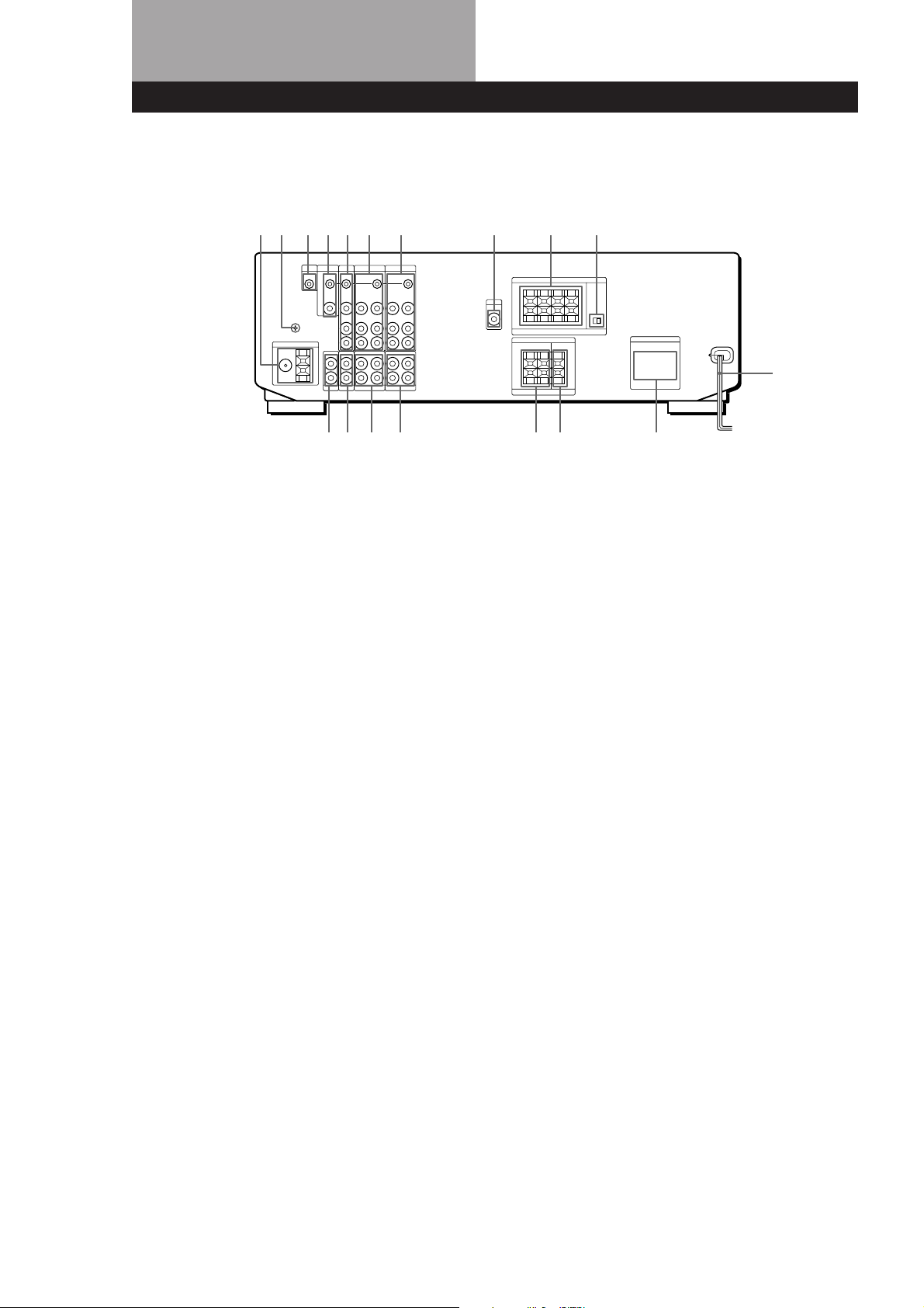
Rear Panel Descriptions
12345
1 ANTENNA (AM/FM)
2 y ground terminal
3 S-LINK CTRL A1 jack
4 MONITOR
5 TV/DBS
6 VIDEO 2
7 VIDEO 1
67 8
!• !¶ !§ !∞ !™!£!¢
8 MIX OUT
9 FRONT SPEAKERS (A/B)
0 IMPEDANCE SELECTOR
!¡ AC power cord
!™ SWITCHED AC OUTLETs
(Outlet shape and position varies
according to destination)
!£ SURROUND SPEAKERS
(CENTER)
9
0
!¡
!¢ SURROUND SPEAKERS
(REAR)
!∞ TAPE MONITOR
!§ DAT/MD
!¶ CD
!• PHONO
26
EN
Page 27

Remote Button Descriptions
For buttons not described on previous pages and buttons with names different from the buttons on the main unit.
Remote
Button
0-9
CH/PRESET
+/–
INDEX
D. SKIP
0/)
=/+
P
Operates
Receiver
CD player/MD
deck/LD player
TV/VCR
Receiver
TV/VCR
Receiver
CD player
CD player
Tape deck/MD
deck/VCR/LD
player
CD player/
MD deck/LD
player
CD player/
Tape deck/MD
deck/LD
player/VCR
Function
Selects preset numbers.
Selects track numbers.
0 selects track 10.
Selects channel numbers.
Scans and selects preset
stations.
Selects preset channels.
Selects station index
names for index select
tuning.
Skips discs (CD player
with multi-disc changer
only.)
Searches tracks (forward
or backward).
Fast forwards or rewinds.
Skips tracks.
Pauses play or record.
(Also starts recording
with components in
record standby.)
Remote
Button
RMS
DIRECTION
RMS CLEAR
RMS
DIRECTION
9/(
ENTER
TV/VIDEO
VISUAL
POWER
TV CONTROL
ON
-/- -
SUB CH +/–
POSITION
SWAP
Operates
Tape deck
Tape deck
Tape deck
TV/VCR
TV/VCR
TV/VCR/
LD player
TV
TV
TV
TV
TV
Function
Selects tape direction (for tape
decks with the RMS* function.)
Clears RMS* program (for tape
decks with the RMS function.)
Programs tracks (tape deck
with the RMS* function only).
Changes channels when used
with 0-9.
Selects input signal: TV input
or video input.
Turns on or off the power.
Turns on the TV, switches the
input to “TV,” and sets the
remote to operate the TV.
Selects the channel entry
mode, either one or two digit
(in Europe only).
Selects preset channels for the
small picture.**
Changes the position of the
small picture.**
Swaps the small and the large
picture.**
(
p
9
r
r + (
CD player/
Tape deck/MD
deck/LD
player/VCR
CD player/
Tape deck/MD
deck/LD
player/VCR
Tape deck
Tape deck
Tape deck/
MD deck/
VCR
Starts play.
Stops play.
Starts play on the reverse
side.
Sets tape decks to the
record standby mode.
Starts recording when
pressed with ( (or 9
on tape deck).
P IN P
JUMP
ANT TV/VTR
MASTER VOL
+/–
MUTING
SLOPE
BAND
* RMS: Random Music Sensor
** Only for Sony TVs with the picture-in-picture function
TV
TV
VCR
TV
TV
—
—
Activates the picture-inpicture function.**
Jumps back and forth between
the previous and current
channels.
Selects output signal from the
antenna terminal: TV signal or
VCR program.
Normally, adjusts the master
volume of the receiver.
If TV CONTROL ON was
pressed, it adjusts the volume
on the TV.
Normally, mutes the sound
from the receiver.
If TV CONTROL ON was
pressed, the sound on the TV
itself is muted.
Not applicable.
Not applicable.
27
EN
Page 28

Index
28
EN
A, B
Adjusting
delay time 19
parameter 17
speaker volume 19
tone 16
volume 9
Antenna hookups 5
Audio component hookups
5, 6
Automatic tuning 11
Background Operation 20
C
Center mode 18, 19, 24
NORMAL mode 19, 24
PHANTOM mode 19, 24
3 CH LOGIC mode 19, 24
WIDE mode 19, 24
Connecting. See Hookups
Customizing
remote 20, 21
sound field 16, 17
D
Delay time 19, 24
Digital Signal Processor. See
DSP
Direct tuning 10, 24
Dolby Pro Logic
Surround 24
getting the most out of 18
Dolby Surround sound 18, 24
center mode 18, 19, 24
Dubbing. See Recording
E, F, G
Editing. See Recording
Effect level 16, 24
H
Hookups
AC power cord 8
antennas 5
audio components 5, 6
overview 4
speakers 6, 7
TV/VCRs 7, 8
I, J, K
Indexing
preset station 12
program source 13
Index tuning 12
L
Labeling. See Indexing
M
Memory page 24
N, O
NORMAL mode 19, 24
P
Parameter 16, 18, 24
PHANTOM mode 19, 24
Preset station 24
Presetting
preset number 11
radio stations 11
Preset tuning 12
Program source
indexing 13
selecting 9
Programming the remote 21
clearing the signal 21
Q
Quick reference guide 29
R
Random Music Sensor. See
RMS
Rear panel
5, 6, 7, 8, 26
Receiving broadcasts
by scanning indexed
stations 12
directly 10
using preset stations 12
Recording
on a tape 13
on a video tape 14
Remote 9, 14, 18, 20, 21, 27
changing the setting 20
controlling non-Sony
components 21
controlling Sony
components 9, 20
background operation 20
programming 21
RMS 27
S
Scanning
indexed stations 12
preset stations 12
radio stations 11
Selecting a program source
using the remote 9, 10
Sleep timer 14
Sound field
adjustable parameters 16
customizing 17
pre-programmed 15
Speakers
connection 6, 7
impedance 7
placement 6
selecting speaker system 7
Station index 12
Storing radio stations. See
Presetting
Surround sound 15, 16, 24
T
Test tone 19, 25
3 CH LOGIC mode 19, 24
Troubleshooting 22
Tuning. See Receiving
broadcasts
TV/VCR hookups 7, 8
U, V
Unpacking 4
W, X, Y, Z
Watching video programs 9
WIDE mode 19, 24
Names of controls
Buttons
ANT TV/VTR/D. SKIP 27
BACKGROUND 20
BASS BOOST 9
CD 9, 10
CENTER LEVEL 19
CENTER MODE 18
CH/PRESET 27
DAT/MD 9, 10
DIGITAL PROCESSING
CONTROLS 12, 18
DIRECT 10
DISPLAY 11, 12
DPC MODE 12, 16, 19
TONE ON/OFF 16
FM MODE 10
GENRE 15, 18
LD 10
LEARN 21
MASTER VOL 27
MEMORY 11
MODE 15, 18
MUTING 9
PHONO 9, 10
PRESET TUNING 12
REAR LEVEL 19
RMS CLEAR 27
9/( RMS DIRECTION 27
RMS/START/ENTER 27
SHIFT 11, 12
SHIFT/>10 27
SLEEP 14
SOUND FIELD
ON/OFF 15, 18
SYSTEM CONTROL/
FUNCTION 10, 20
SYSTEM OFF 10
TAPE MONITOR 9, 13
TEST TONE 19, 25
TUNER 10, 11, 12
TUNING/
INDEX SELECT 12
TV/DBS 9, 10
TV CONTROL ON 10
TV/VIDEO 10, 27
VIDEO 1 9, 10
VIDEO 2 9, 10
VISUAL POWER 27
/ / / 12, 16, 19
0/) 27
=/+ 27
P 27
r 27
Number 10, 11, 20
Switch and selector
POWER 9
SPEAKERS 7
Controls
BALANCE 9
MASTER VOLUME 9, 19
Jacks
PHONES 9
Indicators
DPC 12, 13, 16, 19
LEARN 21
TAPE MONITOR 13
Other
g 4
Page 29

Quick Reference Guide
Receiving Broadcasts
(direct tuning)
Example: Receiving FM
102.50 MHz
TUNER
v
FM/AM
Select FM.
v
DIRECT
v
10 25 0
Display
Receiving Preset
Stations
Example: Receiving station
number A7
TUNER
v
SHIFT
7
Select A.
v
Scanning Preset
Stations
TUNER
v
v
Select the
frequency
display.
DISPLAY
PRESET TUNING
– +
Using Preprogrammed
Sound Fields
Example: Watching a Dolby
Surround-encoded movie on
a laser disc player connected
to VIDEO 2
VIDEO 2
v
SOUND FIELD
ON/OFF
v
SOUND FIELD
GENRE
v
SOUND FIELD
MODE
v
Turn on the LD player.
v
Start playing.
Select
PRO LOGIC
Select
PRO LOGIC
or
ENHANCED
Scanning Radio
Stations
(automatic tuning)
Example: Scanning FM
stations
TUNER
v
v
v
v
Select the
frequency
display
Select FM.
DISPLAY
FM/AM
TUNING
– INDEX SELECT +
TUNING
– INDEX SELECT +
(To continue scanning.)
Selecting a
Component
Example1: Playing a CD
CD
v
Turn on the CD player.
v
Start playing.
Example2: Watching a video
tape
VIDEO 1
v
Turn on the VCR.
v
Start playing.
29
EN
Page 30

ADVERTENCIA
Para evitar incendios y el
riesgo de electrocución, no
exponga la unidad a la
lluvia ni a la humedad.
Precauciones
Seguridad
• Si dentro del receptor cae algún
objeto sólido o líquido, desenchúfelo
y haga que sea revisado por personal
cualificado.
Fuentes de alimentación
• Antes de utilizar el receptor,
compruebe si su tensión de
alimentación es idéntica a la de la red
local. La tensión de alimentación está
indicada en la placa de características
de la parte posterior del receptor.
• El receptor no se desconectará de la
fuente de alimentación de CA (red)
mientras permanezca enchufado a
una toma de la misma, incluso
aunque haya desconectado su
alimentación.
• Cuando no vaya a utilizar el receptor
durante mucho tiempo, desenchúfelo
de la red. Para desconectar el cable
de alimentación, tire del enchufe. No
tire nunca del propio cable.
• Por motivos de seguridad, una de las
cuchillas del enchufe es más ancha
que la otra y solamente encajará en la
toma de la red de una forma. Si no
puede insertar completamente el
enchufe en la toma de la red, póngase
en contacto con su proveedor.
• El cable de alimentación de CA
solamente deberá ser cambiado en un
taller de reparaciones cualificado.
Ubicación
• Coloque el receptor en un lugar
adecuadamente ventilado para evitar
el recalentamiento interior y
prolongar su duración útil.
• No coloque el receptor cerca de
fuentes térmicas, ni sometido a la luz
solar directa, polvo excesivo, ni a los
golpes.
• No coloque nada sobre el receptor, ya
que podría bloquear los orificios de
ventilación y provocar su mal
funcionamiento.
Operación
• Antes de conectar otros componentes,
cerciórese de desconectar la
alimentación de este receptor y de
desconectarlo de la toma de la red.
Limpieza
• Limpie la caja, los paneles, y los
controles con un paño suave
ligeramente humedecido en una
solución poco concentrada de
detergente. No utilice ningún tipo de
estropajos, polvos abrasivos, ni
disolventes como alcohol o bencina.
Si tiene cualquier pregunta o
problema en relación con su
receptor, consulte a su proveedor
Sony más cercano.
E
2
Page 31

Descripción de este
manual
ÍNDICE
Convencionalismos
• En este manual de instrucciones se
describen los controles del receptor.
Usted también podrá utilizar los
controles del telemando si poseen
nombres iguales o similares a los del
receptor.
• En la página 31 se ofrece la “Guía de
referencia rápida”.
• En la sección “Descripción de las
teclas del telemando” de la página 29
se ofrece un resumen de las teclas de
dicho telemando.
• En este manual se utilizan los iconos
siguientes:
Indica que usted podrá utilizar el
telemando para realizar la tarea.
Indica consejos y sugerencias
para facilitar las tareas.
Este receptor posee el sistema Dolby
Surround.
Fabricado bajo licencia de Dolby
Laboratories Licensing Corporation.
DOLBY, el símbolo de la doble D a y
PRO LOGIC son marcas de Dolby
Laboratories Licensing Corporation.
Preparativos
Desembalaje 4
Descripción general de las conexiones 4
Conexión de antenas 5
Conexión de componentes de audio 5
Conexión de sistemas de altavoces 6
Conexión de un televisor/videograbadora 7
Conexión de CA 9
Antes de utilizar su receptor 9
Operaciones del receptor
Selección de un componente 10
Recepción de programas de radiodifusión 12
Memorización de emisoras de radiodifusión 13
Indización 14
Grabación 15
Utilización del temporizador cronodesconectador 16
Utilización de campos acústicos
Utilización de campos acústicos programados 17
Para aprovechar las ventajas de los campos acústicos 18
Personalización de los campos acústicos 18
Disfrute al máximo de sonido Dolby Pro Logic Surround 20
E
Operaciones remotas avanzadas
Control de un componente durante la utilización de otro
(Operación de fondo) 22
Cambio del ajuste de fábrica de una tecla de función 22
Programación del telemando 23
Información adicional
Solución de problemas 24
Especificaciones 25
Glosario 26
Descripción del panel posterior 28
Descripción de las teclas del telemando 29
Índice alfabético 30
Guía de referencia rápida 31
E
3
Page 32

Preparativos
Desembalaje
Compruebe si ha recibido los accesorios siguientes con
el receptor:
• Antena monofilar de FM (1)
• Antena de cuadro de AM (1)
• Telemando (1)
• Pilas de tamaño AA (R6) (2)
• Cable de audio/vídeo (1)
• Cable de control S (1)
Colocación de las pilas en el telemando
Inserte dos pilas de tamaño AA (R6) de acuerdo con +
y – del compartimiento de las mismas. Cuando utilice
el telemando, apunte con él hacia el sensor de control
remoto g del receptor.
Descripción general de las
conexiones
El receptor le permitirá conectar y controlar los
componentes de audio/vídeo siguientes. Para conectar
al receptor los componentes deseados, siga los
procedimientos de las páginas especificadas. Para
aprender la ubicación y el nombre de cada toma,
consulte “Descripción del panel posterior” de la página
28.
Conexión de un
Conexión de
un sistema de
altavoces (6, 7)
Altavoz
delantero
(izquierdo)
televisor/
videograbadora
(7, 8)
Televisor
Videograbadora
Reproductor de
discos láser
Conexión de antenas (5)
Antena de AM/FM
Altavoz
de
graves
activo
Altavoz
delantero
(derecho)
Cuándo reemplazar las pilas
En utilización normal, las pilas durarán unos 6 meses.
Cuando el telemando no pueda controlar el receptor,
reemplace ambas pilas por otras nuevas.
Notas
• No deje el telemando en un lugar extremadamente cálido
ni húmedo.
• No utilice una pila nueva con otra vieja.
• No exponga el sensor de control remoto a la luz solar
directa ni a la de aparatos de iluminación. Si lo hiciese,
podría causar un mal funcionamiento.
• Cuando no vaya a utilizar el telemando durante mucho
tiempo, extráigale las pilas a fin de evitar el daño que
podría causar el electrólito de las mismas.
Altavoz
trasero
(izquierdo)
Conexión de componentes
de audio (5, 6)
Reproductor de
discos compactos
Deck de cassettes
Deck de cinta
audiodigital/deck de
minidiscos
Giradiscos
Altavoz
central
Altavoz
trasero
(derecho)
Antes de comenzar
• Antes de realizar cualquier conexión, desconecte la
alimentación de todos los componentes.
• No conecte el cable de alimentación de CA antes de
haber realizado todas las conexiones.
• Cerciórese de realizar conexiones firmes para evitar
zumbidos y ruidos.
• Cuando conecte un cable de audio/vídeo, cerciórese
de hacer coincidir las clavijas codificadas en color
con las tomas apropiadas de los componentes.
Amarilla (vídeo) a amarilla, blanca (canal izquierdo
de audio) a blanca, y roja (canal derecho de audio) a
roja.
E
4
Page 33

Conexión de antenas
Descripción general
En esta sección se describe cómo conectar antenas de
AM y FM al receptor. Si desea recibir emisiones de
radiodifusión con este receptor, realice en primer lugar
estas conexiones, y después vaya a las páginas
siguientes.
Con respecto a la ubicación específica de los
terminales, consulte la ilustración siguiente.
ANTENNA
Preparativos
Conexión de un conductor de puesta a
tierra
Para evitar zumbidos, conecte un conductor de puesta
a tierra (no suministrado) al terminal de puesta a tierra
y. Si ha conectado una antena exterior, cerciórese de
conectar la puesta a tierra como protección contra
rayos.
Receptor
.
a tierra
¿Qué hacer a continuación?
Si desea conectar otros componentes, vaya a la sección
siguiente. Si solamente tiene planeado utilizar el receptor
para escuchar la radio, vaya a “Conexión de sistemas de
altavoces” de las páginas 6 y 7.
¿Qué antenas se necesitan?
• Antena monofilar de
FM (suministrada) (1)
• Antena de cuadro de
Conexiones
Antena
monofilar de FM
Después de haber
conectado la antena
monofilar de FM,
manténgala lo más
horizontalmente
posible.
Si la recepción de FM es deficiente
Conecte un cable coaxial de 75 ohmios (no
suministrado) a una antena exterior de FM.
Antena exterior de FM
Receptor
ANTENNA
FM
75Ω
COAXIAL
Receptor
ANTENNA
FM
75Ω
COAXIAL
AM
AM (suministrada) (1)
Antena de
cuadro de AM
AM
Conexión de componentes de
audio
Descripción general
En esta sección se describe cómo conectar sus
componentes de audio al receptor. Si desea utilizar el
receptor como amplificador, realice estas conexiones.
Con respecto a la ubicación específica de los
terminales, consulte la ilustración siguiente.
TAPEToma S-LINK CTRL A1
PHONO DAT/MD
¿Qué cables se necesitan?
Cables conectores de audio (no suministrados) (1 para el
reproductor de discos compactos y el giradiscos, 2 para el
deck de cassettes, el deck de cinta audiodigital, o el deck de
minidiscos)
Blanca (canal
izquierdo)
Roja (canal
derecho)
CD
Blanca (canal
izquierdo)
Roja (canal
derecho)
(Continúa)
E
5
Page 34

Preparativos
Conexiones
La flecha ç indica el flujo de la señal.
Reproductor de discos compactos
Receptor
IN
L
R
CD
Deck de cassettes
INREC OUT
L
R
TAPE MONITOR
Deck de cinta audiodigital/deck de minidiscos
Receptor
INREC OUT
L
R
DAT/MD
Reproductor de
discos compactos
OUTPUT
LINE
L
R
Deck de cassettesReceptor
OUTPUT
INPUT
LINELINE
L
R
Deck de cinta
audiodigital/deck de
minidiscos
OUTPUT
INPUT
LINELINE
L
R
¿Qué hacer a continuación?
Vaya a la sección siguiente para conectar los altavoces.
Conexión de sistemas de
altavoces
Descripción general
En esta sección se describe cómo conectar sus altavoces
al receptor. Aunque se requieren altavoces delanteros
(izquierdo y derecho), el central y los traseros son
opcionales.
La adición de un altavoz central y de altavoces traseros
reforzará los efectos perimétricos. La conexión de un
altavoz de graves activo aumentará la respuesta en
graves.
Con respecto a la ubicación específica de los
terminales, consulte la ilustración siguiente.
FRONT SPEAKERS AMIX OUT
IMPEDANCE
SELECTOR
Giradiscos
Receptor
IN
L
R
PHONO
• Si su giradiscos posee conductor de puesta a tierra
Para evitar zumbidos, conecte el conductor de puesta a
tierra al terminal de tierra y del receptor.
Conexión de CONTROL A1
Giradiscos
OUTPUT
LINE
L
R
SURROUND
SPEAKERS REAR
SURROUND
SPEAKERS CENTER
Para obtener el óptimo efecto de sonido perimétrico,
coloque los altavoces como se muestra en la ilustración
siguiente.
45°
Altavoz
delantero
Altavoz trasero
60 - 90 cm
• Si posee un reproductor de discos compactos o un
deck de cassettes Sony compatible con CONTROL A1
Utilice un cable CONTROL A1 (no suministrado) para
conectar la toma S-LINK CTRL A1 del reproductor de
discos compactos o del deck de cassettes a la toma S-LINK
CTRL A1 del receptor. Con respecto a los detalles,
consulte el manual separado “Sistema de control
CONTROL-A1” y el Manual de instrucciones
suministrado con su reproductor de discos compacto o su
deck de cassettes.
• Si posee un cambiador de discos compactos Sony con
selector COMMAND MODE
Si el selector COMMAND MODE del cambiador de discos
compactos puede cambiarse entre CD 1, CD 2, y CD 3,
cerciórese de ajustar el modo de mando a “CD 1” y de
conectar el cambiador a las tomas CD del receptor.
Sin embargo, si posee un cambiador de discos compactos
Sony con tomas VIDEO OUT, ajuste el modo de mando a
“CD 2” y conecte el cambiador a las tomas VIDEO 2 del
E
6
receptor.
¿Qué cables se necesitan?
Cable de altavoz (no suministrado) (1 para cada altavoz)
(+)
(–)
Retuerza unos 15 mm de los extremos pelados del cable.
Cerciórese de hacer coincidir el conductor del cable de
altavoz con el terminal apropiado del componente: + a + y –
a –. Si invirtiese los conductores, el sonido se oiría
distorsionado, y se produciría la carencia de graves.
(+)
(–)
Page 35

Preparativos
Conexiones
Altavoces delanteros
Altavoz delantero
(derecho)
} ]} ]
Receptor
FRONT SPEAKERS
R L
AA
IMPEDANCE USE 4-16 Ω
Altavoces traseros y central
Altavoz trasero
(derecho)
SURROUND SPEAKERS
REAR LR CENTER
} ]} ]
LR
IMPEDANCE USE 8-16 Ω
Altavoz
centralReceptor
Altavoz de graves activo
Receptor
MIX
AUDIO
OUT
Altavoz de
graves activo
INPUT
Altavoz
delantero
(izquierdo)
} ]
Altavoz
trasero
(izquierdo)
Selección del sistema de altavoces
Cuando haya conectado un solo juego de altavoces
delanteros, ponga el selector SPEAKERS del panel
frontal en A. Si ha conectado dos juegos de altavoces,
consulte lo siguiente:
ponga el selector
Para excitar
el sistema de altavoces A
(conectado a los terminales
FRONT SPEAKERS A)
el sistema de altavoces B
(conectado a los terminales
FRONT SPEAKERS B)
ambos sistemas de altavoces,
A y B (conexión en paralelo)
* No utilice A+B con SOUND FIELD en ON.
SPEAKERS en
A
B
A+B*
¿Qué hacer a continuación?
Para completar su sistema, vaya a “Conexión de CA” de la
página 9. Si desea conectar componentes de vídeo para
disfrutar de sonido perimétrico cuando contemple programas
de televisión o videocintas, vaya a la sección siguiente.
Si posee un sistema de altavoces delanteros
adicional
Conéctelo a los terminales FRONT SPEAKERS B.
Si su monitor de televisión utiliza altavoces
separados
Usted podrá conectar uno de ellos a los terminales
SURROUND SPEAKER CENTER para conseguir sonido
perimétrico Dolby Pro Logic Surround (consulte la
página 20).
Selección de la impedancia
Ajuste IMPEDANCE SELECTOR para los altavoces
delanteros como se indica en la tabla siguiente. Si no
está seguro de la impedancia, consulte el manual de
instrucciones de sus altavoces. (Esta información
normalmente está impresa en una etiqueta en la parte
posterior del altavoz.)
Si la impedancia nominal
de su altavoz es
entre 4 y 8 ohmios
ponga IMPEDANCE
SELECTOR en
4 Ω
Conexión de un televisor/
videograbadora
Descripción general
En esta sección se describe cómo conectar componentes
de vídeo al receptor.
Con respecto a la ubicación específica de los
terminales, consulte la ilustración siguiente.
TV
MONITOR
VIDEO 2
VIDEO 1
(Continúa)
de 8 ohmios o más
8 Ω
E
7
Page 36

Preparativos
OUTPUT
VIDEO
AUDIO
VIDEO 2
CTRL S
OUT
VIDEO
IN
VIDEO
OUT
AUDIO
IN
AUDIO
OUT
S-LINK
L
R
L
R
¿Qué cables se necesitan?
• Cable de audio/vídeo (no suministrado) (1 para el
televisor o el reproductor de discos láser; 2 para la
videograbadora)
Amarilla
Blanca (canal
izquierdo)
Roja (canal
derecho)
Amarilla
Blanca (canal
izquierdo)
Roja (canal
derecho)
• Cable de vídeo (no suministrado) (1 para un televisor)
Amarilla
Amarilla
Conexiones
La flecha ç indica el flujo de la señal.
Televisor o sintonizador del sistema de radiodifusión
digital (DBS)
Receptor
TV/DBS
CTRL S
STATUS IN
VIDEO
IN
AUDIO
IN
L
R
Televisor o sintonizador
del sistema de
radiodifusión digital (DBS)
OUTPUT
VIDEO
AUDIO
L
R
Reproductor de discos láser (a través de las tomas
VIDEO 2)
Receptor
Reproductor de discos láser
• Si posee un televisor, sintonizador del sistema de
radiodifusión digital, monitor, videograbadora, o
reproductor de discos láser Sony compatible con
CONTROL S
Utilice el cable CONTROL S (suministrado) para conectar
la toma S-LINK CTRL S IN (para el televisor, el
sintonizador del sistema de radiodifusión digital, o el
monitor) u OUT (para la videograbadora o el reproductor
de discos láser) del receptor a la toma S-LINK apropiada
del componente respectivo. Con respecto a los detalles,
consulte el Manual de instrucciones suministrado con su
televisor, sintonizador del sistema de radiodifusión
digital, monitor, videograbadora, o reproductor de discos
láser.
Monitor de televisión
Si utiliza un monitor de televisión, no conecte nada a la
toma TV/DBS VIDEO IN.
Receptor
MONITOR
CTRL S
IN
VIDEO
OUT
Monitor de
televisión
INPUT
VIDEO
Videograbadora (a través de las tomas VIDEO 1)
Si posee dos videograbadoras, conecte la segunda a las
tomas VIDEO 2.
Receptor
VIDEO 1
CTRL S
OUT
S-LINK
VIDEO
VIDEO
IN
OUT
AUDIO
AUDIO
IN
OUT
L
R
Videograbadora
OUTPUT
INPUT
VIDEO VIDEO
AUDIO AUDIO
L
R
¿Qué hacer a continuación?
Vaya a la sección siguiente para conectar el enchufe de CA y
completar su sistema de teatro para el hogar.
E
8
Page 37

Preparativos
Conexión de CA
Conexión de los cables de alimentación
Conecte el cable de alimentación de este receptor y de
los componentes de audio/vídeo a tomas de la red.
Si conecta los otros componentes de audio a
SWITCHED AC OUTLETS del receptor, éste podrá
suministrar alimentación a los componentes
conectados a fin de poder conectar/desconectar la
alimentación de todo el sistema cuando conecte/
desconecte la del receptor.
SWITCHED AC OUTLETS
/
a una toma de la
red
Precaución
Cerciórese de que el consumo de los componentes
conectados al tomacorriente de CA del receptor no sobrepase
el vataje indicado en el panel posterior. No conecte
electrodomésticos de gran vataje, como planchas eléctricas,
ventiladores, ni televisores a este tomacorriente.
Antes de utilizar su receptor
Antes de comenzar a utilizar su receptor, cerciórese de
haber:
• Girado MASTER VOLUME completamente hacia
la posición extrema izquierda (0).
• Seleccionado el sistema de altavoces apropiado.
(Consulte “Selección del sistema de altavoces” de
la página 7.)
• Puesto BALANCE en la posición central.
Conecte la alimentación del receptor y compruebe el
indicador siguiente.
• Si en el visualizador está indicándose MUTING,
presione MUTING del telemando.
¿Qué hacer a continuación?
Antes de utilizar el receptor, vaya a la sección siguiente para
cerciorarse de que todos los controles estén ajustados en las
posiciones apropiadas.
E
9
Page 38

Operaciones del receptor
Selección de un componente
Para escuchar o contemplar un componente conectado,
seleccione en primer lugar la función en el receptor o
con el telemando.
Antes de comenzar, cerciórese de haber:
• Conectado todos los componentes con seguridad y
correctamente como se indica en las páginas 5 a 8.
• Girado MASTER VOLUME hacia la posición extrema
izquierda (0) para evitar dañar sus altavoces.
4 Gire MASTER VOLUME para ajustar el volumen.
Para ajustar el volumen de los altavoces del
televisor, utilice el control de volumen del mismo.
Para
silenciar el sonido
reforzar los graves
haga lo siguiente
presione MUTING del telemando.
Para restablecer el sonido, vuelva a
presionarla.
presione BASS BOOST de forma que
se encienda el indicador BASS
BOOST.
MASTER VOLUMEPOWER
Teclas de función
1 Presione el botón POWER para conectar la
alimentación del receptor.
2 Presione una tecla de función para seleccionar el
componente que desee utilizar:
Para escuchar o contemplar
discos analógicos
programas de radiodifusión
discos compactos
cintas audiodigitales (DAT) o
minidiscos (MD)
presione
PHONO
TUNER
CD
DAT/MD
ajustar el equilibrio
gire el control BALANCE hacia la
izquierda o la derecha.
Para escuchar a través de auriculares
Conecte los auriculares a la toma PHONES y ponga las
teclas SPEAKERS en OFF.
Contemplación de programas de vídeo
Para contemplar programas de teledifusión o de vídeo,
recomendamos que reproduzca la parte de audio a
través del receptor en vez de utilizar el altavoz de su
televisor. Esto le permitirá aprovechar las ventajas de
los efectos de sonido perimétrico del receptor, como
Dolby Surround, y utilizar el telemando del receptor
para controlar el sonido.
Desconecte los altavoces de su televisor antes de
comenzar a disfrutar del sonido perimétrico del
receptor.
Para contemplar programas de televisión, conecte la
alimentación del televisor y del receptor, y presione la tecla
TV del receptor.
10
cintas de audio
programas de televisión
cintas de vídeo
discos láser
TAPE MONITOR
TV/DBS
VIDEO 1 o
VIDEO 2
VIDEO 2
Para contemplar videocintas o discos láser, realice lo
siguiente:
1 Presione una tecla de función para seleccionar el
componente (por ejemplo, VIDEO 1).
2 Conecte la alimentación del televisor y ajuste la
entrada de vídeo del mismo de acuerdo con su
3 Conecte la alimentación del componente, por
componente de vídeo.
ejemplo un reproductor de discos compactos, e
inicie la reproducción.
Para sintonizar emisoras de radiodifusión en este
receptor, consulte “Recepción de programas de
3 Conecte la alimentación del componente
(videograbadora o reproductor de discos láser), e
inicie la reproducción.
radiodifusión” de la página 12.
E
Page 39

Operaciones del receptor
Utilización del telemando
El telemando le permitirá controlar el receptor y los
componentes Sony a él conectados.
SYSTEM
OFF
SYSTEM
TV CONTROL
ON
CONTROL/
FUNCTION
1 Presione una de las teclas SYSTEM CONTROL/
FUNCTION para seleccionar el componente que
desee utilizar.
Se conectará la alimentación del receptor y la del
componente seleccionado.
Las teclas SYSTEM CONTROL/FUNCTION del
telemando han sido ajustadas en fábrica de la
forma siguiente:
Para escuchar o
contemplar
discos analógicos
programas de radiodifusión
discos compactos
presione
PHONO
TUNER
CD
2 Inicie la reproducción.
Con respecto a los detalles, consulte “Descripción
de las teclas del telemando” de la página 29.
Para desconectar la alimentación de los componentes
Presione SYSTEM OFF. Usted podrá desconectar al mismo
tiempo la alimentación de los componentes de vídeo y de
audio conectados a SWITCHED AC OUTLETS del panel
posterior de esta unidad.
Si está utilizando un televisor Sony
Cuando presione TV para contemplar un programa de
televisión, se conectará la alimentación del televisor y
cambiará a la entrada de televisión. La alimentación del
televisor también se conectará automáticamente y
cambiará a la entrada de vídeo apropiada cuando
presione VIDEO 1 o VIDEO 2. Si el televisor no cambia
automáticamente a la entrada apropiada, presione
TV/VIDEO del telemando.
Contemplación de televisión sin el receptor (para
televisores Sony solamente)
Presione TV CONTROL ON para hacer que el
telemando controle las funciones del televisor
solamente (con respecto a los detalles, consulte
“Descripción de las teclas del telemando” de la página
29). Cuando presione esta tecla, se conectará la
alimentación del televisor y cambiará a la entrada de
televisor. Si el televisor no cambia automáticamente a
la entrada de televisor, presione TV/VIDEO.
cintas audiodigitales (DAT)
o minidiscos (MD)
cintas de audio
programas de televisión
cintas de vídeo
discos láser
* Las videograbadoras Sony se controlan con el ajuste
VTR 1, 2, o 3, que corresponden, respectivamente, a
Beta, 8 mm, y VHS.
** VIDEO 3 y LD ajustan el telemando para controlar los
componentes de vídeo Sony respectivos, pero no
cambian la función del receptor.
Por ejemplo, para controlar un reproductor de discos
láser Sony conectado a las tomas VIDEO 2 (como se
muestra en la página 8):
Presione VIDEO 2 para cambiar la función, y después
presione LD a fin de ajustar el telemando para
controlar el reproductor de discos láser.
DAT/MD
TAPE
TV/DBS
VIDEO 1 (VTR 1*)
VIDEO 2 (VTR 2*) o
VIDEO 3** (VTR 3*)
LD**
Si desea cambiar el ajuste de fábrica de una tecla
Consulte la página 22.
Si no se conecta la alimentación del componente
Presione el interruptor de alimentación del componente
seleccionado.
11
E
Page 40

Operaciones del receptor
Recepción de programas de
radiodifusión
Si el indicador STEREO permanece apagado
Presione FM MODE incluso cuando se reciba una
emisión de FM estéreo.
Este receptor le permitirá introducir directamente la
frecuencia de una emisora utilizando las teclas
numéricas (sintonía directa). Si no conoce la frecuencia
de la emisora deseada, consulte “Recepción de
programas de radiodifusión explorando emisoras
(sintonía automática)”.
Antes de comenzar, cerciórese de haber:
• Conectado una antena de FM/AM al receptor como
se indica en la página 5.
• Seleccionado el sistema de altavoces apropiado.
(Consulte “Selección del sistema de altavoces” de la
página 7.)
POWER MASTER VOLUME
Teclas numéricas
TUNERDIRECT
– INDEX SELECT +
FM/AM
TUNING/
1 Presione POWER para conectar la alimentación
del receptor.
2 Presione TUNER.
Se sintonizará la última emisora recibida.
3 Presione FM/AM para seleccionar emisoras de
FM o de AM.
4 Presione DIRECT.
5 Presione las teclas numéricas para introducir la
frecuencia.
Ejemplo 1: FM 102,50 MHz Ejemplo 2: AM 1350 kHz
1 0 2 5 0
(Usted no necesitará
introducir el último “0”.)
1 3 5
Si un programa de FM estéreo se oye distorsionado
El indicador STEREO parpadeará. Presione FM MODE
para cambiar a monoaural (MONO). Usted no tendrá
efecto estéreo, pero la distorsión se reducirá. Para
volver al modo de estéreo automático, presione de
nuevo esta tecla.
Si no puede sintonizar una emisora, y los números
introducidos parpadean
Compruebe si ha introducido la frecuencia correcta. Si
no es correcta, presione DIRECT y vuelva a introducir la
frecuencia deseada.
Si los números introducidos continúan parpadeando, la
frecuencia no estará utilizándose en su zona.
Para contemplar programas de teledifusión con
emisión simultánea en FM
Cerciórese de sintonizar el programa de emisión
simultánea en el televisor (o la videograbadora) y en el
receptor.
Si introduce una frecuencia no cubierta por el
intervalo de sintonía
El valor introducido se redondeará automáticamente
por exceso o defecto hasta el valor más cercano cubierto.
Los intervalos para la sintonía directa son:
FM: intervalo de 50 kHz
AM:intervalo de 10 kHz (Para cambiar al intervalo de
9 kHz, consulte la página 25.)
Recepción de programas de radiodifusión
explorando emisoras (sintonía automática)
Si no conoce la frecuencia de la emisora deseada, podrá
hacer que el receptor explore todas las emisoras
recibibles hasta localizar dicha emisora.
1 Presione TUNER.
Se sintonizará la última emisora recibida.
2 Presione DISPLAY de forma que en el
visualizador aparezca la frecuencia.
3 Presione FM/AM para seleccionar FM o AM.
12
6 Cuando sintonice emisoras de AM, ajuste la
orientación de la antena de cuadro de AM hasta
obtener la óptima recepción.
Para recibir otras emisoras
Repita los pasos 3 a 5.
E
Presione la tecla + para un número de emisora
superior, o – para un número inferior. Cuando
llegue al final de la banda, el receptor saltará
automáticamente al extremo puesto. Cada vez
que se reciba una emisora, el receptor parará la
exploración. Para continuar explorando, presione
de nuevo la tecla.
4 Presione TUNING/INDEX SELECT + o –.
Page 41

Operaciones del receptor
Si la exploración se para con demasiada frecuencia
(banda de FM solamente)
Salte las emisoras con señal débil. Presione LEVEL. En
el visualizador aparecerá “HIGH” y el receptor
explorará solamente las emisoras con señal intensa.
Memorización de emisoras de
radiodifusión
Seguramente deseará memorizar en el receptor las
emisoras que escuche más a menudo a fin de no tener
que sintonizarlas cada vez. El receptor podrá
almacenar un total de 30 emisoras de FM o de AM.
Usted podrá almacenar emisoras en números de
memorización compuestos por tres caracteres (A, B, C)
y números (0-9). Por ejemplo, podrá almacenar una
emisora en el número de memorización A1, B6, C9, etc.
Teclas numéricas
SHIFT
Para cambiar una emisora memorizada
Almacene una nueva emisora en el número que desee
cambiar.
Nota
Si el cable de alimentación permanece desconectado durante
aproximadamente una semana, las emisoras memorizadas se
borrarán de la memoria del receptor, y tendrá que volver a
almacenarlas.
Sintonía de emisoras memorizadas
(sintonía memorizada)
Usted podrá sintonizar directamente una emisora
introduciendo su número de memorización. Si no sabe
qué emisoras están memorizadas en los números,
podrá sintonizar explorando las emisoras
memorizadas.
1 Presione TUNER.
Se recibirá la última emisora sintonizada.
2 Presione SHIFT para seleccionar un carácter (A, B,
o C), y después presione el número.
Por ejemplo, seleccione A y después presione 7
para sintonizar la emisora memorizada como A7.
TUNER MEMORY
1 Presione TUNER.
Se sintonizará la última emisora recibida.
2 Sintonice la emisora deseada.
Si no está familiarizado con la forma de sintonizar
una emisora, consulte “Recepción de programas
de radiodifusión” de la página 12.
3 Presione MEMORY.
“MEMORY” aparecerá durante algunos
segundos.
Realice los pasos 4 y 5 antes de que desaparezca
“MEMORY”.
4 presione SHIFT para seleccionar un carácter (A, B,
o C).
Cada vez que presione SHIFT, en el visualizador
aparecerá la letra “A”, “B”, o “C”.
5 Presione el número deseado (0 a 9).
Si “MEMORY” desaparece antes de haber
especificado el número de memorización, comience
de nuevo desde el paso 3.
Usted podrá sintonizar explorando las emisoras
memorizadas
Presione TUNER y a continuación DISPLAY para que se
visualice la frecuencia. Después, presione PRESET
TUNING + o – para seleccionar la emisora deseada.
Cada vez que presione las teclas, los números de
memorización cambiarán de la forma siguiente:
n A1 ˜ A2 ˜ … ˜ A0 ˜ B1 ˜ B2 ˜ … ˜ B0 N
n C0 ˜ … ˜ C2 ˜ C1 N
6 Repita los pasos 2 a 5 para memorizar otras
emisoras.
13
E
Page 42

Operaciones del receptor
Indización
Usted podrá indizar las emisoras memorizadas y
después utilizar los nombres de indización para
explorar emisoras específicas de la memoria.
Usted también podrá utilizar la función de indización
para asignar etiquetas a fuentes de programas para que
el receptor visualice los nombres de los componentes
que haya conectado, por ejemplo, “VHS”.
PRESET TUNING +/–DPC MODE
Para insertar un espacio, presione o hasta
que en el visualizador aparezca un espacio en
blanco (el espacio está entre “}” y “!”).
El nombre de índice de emisora se almacenará
automáticamente.
Si ha cometido un error
Presione repetidamente o hasta que parpadee el
carácter que desee cambiar. Después seleccione el
carácter correcto.
5 Repita los pasos 2 a 4 para asignar nombres a
otras emisoras.
Usted podrá hacer que se visualice el nombre de
índice o la frecuencia.
Cada vez que presione DISPLAY, la visualización
cambiará entre la frecuencia y el nombre de índice.
Teclas de
control de
proceso digital
TUNER MEMORY
DISPLAYTUNING/
INDEX SELECT +/–
Indización de emisoras memorizadas
Usted puede darse cuenta de que resulta difícil
encontrar la emisora deseada cuando hay muchas
memorizadas. Este receptor incluye una función que le
permitirá agrupar las emisoras por nombres (índice de
emisora) utilizando hasta 8 caracteres.
Por ejemplo, si asigna la etiqueta “JAZZ” a todas las
emisoras memorizadas de jazz, seleccionando “JAZZ”
podrá saltar otras emisoras y explorar solamente las
pertenecientes a la etiqueta “JAZZ”. Tenga en cuenta
que no podrá asignar más de un nombre de índice a
cada emisora memorizada.
1 Presione TUNER.
Se recibirá la última emisora sintonizada.
2 Sintonice la emisora memorizada que desee
indizar. Si no está familiarizado con la sintonía
de emisoras memorizadas, consulte “Sintonía de
emisoras memorizadas (sintonía memorizada)”
anterior.
3 Presione repetidamente DPC MODE hasta que se
encienda el indicador INDEX.
Exploración de emisoras indizadas (sintonía
indizada)
Después de haber seleccionado un índice de emisoras,
podrá explorar todas las emisoras de tal índice.
1 Presione TUNER.
Se sintonizará la última emisora recibida.
2 Presione DISPLAY de forma que en el
visualizador aparezca el modo de índice.
En el visualizador aparecerá el índice de emisoras
para la última emisora recibida.
Si aparece “_ _ _ _”
La emisora no está indizada.
3 Presione TUNING/INDEX SELECT + o – para
seleccionar el índice de emisoras que desee
explorar.
4 Para seleccionar la emisora que desee recibir,
presione PRESET TUNING + o –.
Para seleccionar diferentes índices de emisoras
Presione TUNING/INDEX SELECT + o – para seleccionar el
índice deseado, y después PRESET TUNING + o – para
seleccionar la emisora.
14
4 Cree un nombre de emisora utilizando las teclas
de control de proceso digital de la forma
siguiente:
Presione
después
siguiente.
E
o para seleccionar un carácter, y
para mover el cursor hasta la posición
Page 43

Indización de fuentes de programas
Esta función será muy útil cuando, por ejemplo, posea
más de una videograbadora: usted podrá asignar
“VHS” a una de ellas y “8MM” a otra. Después, podrá
hacer que el receptor visualice los nombres de índice
para saber qué videograbadora está utilizando. Esta
función también será útil si ha conectado un
componente a las tomas diseñadas para otro (por
ejemplo, si ha conectado un segundo reproductor de
discos compactos a las tomas DAT/MD).
Operaciones del receptor
Grabación
Este receptor facilita la grabación en y desde los
componentes conectados al mismo. Usted no tendrá
que conectar directamente componentes de
reproducción y grabación: una vez seleccionada una
fuente de programas en el receptor, podrá grabar y
editar como lo haría normalmente utilizando los
controles de cada componente.
1 Presione la tecla FUNCTION a la que desee
asignar un nombre.
2 Presione repetidamente DPC MODE hasta que se
encienda el indicador INDEX.
3 Cree un nombre utilizando las teclas de control de
proceso digital de la forma siguiente:
Presione
después
siguiente.
Para insertar un espacio, presione
que en el visualizador aparezca un espacio en
blanco (el espacio está entre “}” y “!”).
El nombre de emisora creado se almacenará
automáticamente.
Si ha cometido un error
Presione repetidamente o hasta que parpadee el
carácter que desee cambiar. Después seleccione el
carácter correcto.
Usted podrá hacer que se visualice el nombre de
índice o la frecuencia.
Cada vez que presione DISPLAY, la visualización
cambiará entre la frecuencia y el nombre de índice.
o para seleccionar un carácter, y
para mover el cursor hasta la posición
o hasta
Antes de comenzar, cerciórese de haber conectado
adecuadamente todos los componentes.
c
Teclas de función
c
ç
Componente para
reproducción (fuente
de programas)
ç: Flujo de la señal de audio
c: Flujo de la señal de vídeo
Componente para grabación
(Deck de cassettes, deck de
minidiscos, videograbadora)
ç
Grabación en un cassette de audio o en un
minidisco
Usted podrá grabar en un deck de cassettes, un deck de
cinta audiodigital, o un deck de minidiscos utilizando
el receptor. Si necesita ayuda, consulte el manual de
instrucciones del deck de cassettes, del deck de cinta
audiodigital, o del deck de minidiscos.
1 Presione la tecla de función correspondiente al
componente que desee grabar.
2 Prepare el componente y déjelo listo para
reproducir.
Por ejemplo, inserte un disco compacto en el
reproductor de discos compactos.
3 Inserte un cassette en blanco en el deck para
grabación y, si es necesario, ajuste el nivel de
grabación.
4 Inicie la grabación en el deck para grabación y
después ponga en reproducción el componente.
(Continúa)
15
E
Page 44

Operaciones del receptor
Usted podrá escuchar el sonido que esté grabándose
Si ha conectado un deck de cassettes de 3 cabezas a las
tomas TAPE MONITOR y presione TAPE MONITOR.
El indicador TAPE MONITOR se encenderá, y podrá oír
el sonido que esté grabándose.
Nota
Cuando grabe en un deck de cinta audiodigital/deck de
minidiscos conectado a las tomas DAT/MD REC OUT, los
ajustes del sonido no afectarán la grabación.
Grabación en un cassette de vídeo
Usted podrá grabar de una videograbadora, un
televisor, o un reproductor de discos láser utilizando el
receptor. También podrá añadir audio desde gran
variedad de fuentes de audio cuando edite una cinta de
vídeo. Si necesita ayuda, consulte el manual de
instrucciones de su videograbadora o de su
reproductor de discos láser.
1 Presione la tecla de función correspondiente a la
fuente de programa que desee grabar.
Utilización del temporizador
cronodesconectador
Usted podrá ajustar el receptor para que su
alimentación se desconecte automáticamente después
del tiempo especificado.
SLEEP
Presione SLEEP del telemando mientras la
alimentación esté conectada.
Cada vez que presione SLEEP, el tiempo cambiará de
la forma siguiente.
2 Prepare el componente y déjelo listo para
reproducir.
Por ejemplo, inserte el disco láser que desee
grabar en el reproductor de discos láser.
3 Inserte un videocassette en blanco en la
videograbadora (VIDEO 1 o VIDEO 2) para
grabación.
4 Inicie la grabación en la videograbadora para
grabación y después ponga en reproducción la
videocinta o el disco láser que desee grabar.
Usted podrá reemplazar sonido durante la copia de
una videocinta o un disco láser
En el punto en el que desee iniciar la adición de sonido
diferente, presione otra tecla de función (por ejemplo,
CD) y comience la reproducción. El sonido del
componente seleccionado se grabará sobre la parte de
audio original.
Para reanudar la grabación del sonido de la fuente de
reproducción original, presione la tecla de función
correspondiente a tal componente.
n 2:00:00 n 1:30:00 n 1:00:00 n 0:30:00 n OFF
El brillo de visualización se reducirá después de haber
especificado el tiempo.
Usted podrá especificar libremente el tiempo
Presione en primer lugar SLEEP, y después especifique
el tiempo utilizando las teclas de proceso digital ( o
). El tiempo cambiará a intervalos de 1 minuto.
Usted podrá especificar hasta 5 horas.
Usted podrá comprobar el tiempo restante hasta
que se desconecte la alimentación del receptor
Presione SLEEP. En el visualizador aparecerá el tiempo
restante.
16
E
Page 45

Utilización de campos acústicos
Utilización de campos acústicos
programados
Usted podrá aprovechar las ventajas del sonido
perimétrico seleccionando simplemente uno de los
cinco campos acústicos programados de acuerdo con el
programa que desee reproducir.
SOUND FIELD
ON/OFF
GENRE
1 Presione SOUND FIELD ON/OFF para activar el
campo acústico.
Uno de los indicadores se encenderá en el
visualizador.
2 Presione GENRE para seleccionar el tipo de
campo acústico deseado.
3 Presione MODE para seleccionar el modo deseado
del género respectivo.
Seleccione el campo acústico apropiado de
acuerdo con la tabla siguiente.
Para reproducir sin efectos perimétricos
Seleccione “ACOUSTIC” de MUSIC 2. Los efectos
perimétricos se anularán, pero todavía podrá ajustar el
parámetro del tono (consulte la página 19).
Para desactivar los campos acústicos
Presione SOUND FIELD ON/OFF.
Usted podrá encontrar software codificado con
Dolby Surround observando el paquete.
Sin embargo, algunos videocassettes y discos láser
pueden utilizar sonido Dolby Surround incluso aunque
no esté indicado en el paquete.
Nota
Cerciórese de seleccionar ambos altavoces (A+B) con el
selector SPEAKERS cuando esté utilizando dos juegos de
altavoces, ya que de lo contrario no podría obtener el efecto
perimétrico completo.
MODE
Utilización de campos acústicos
Campos acústicos
GÉNERO MODO para
PRO LOGIC PRO LOGIC decodificar programas
procesados con Dolby
Surround.
ENHANCED proporcionar salida
adicional a los
altavoces traseros
después de haber
decodificado
programas procesados
con Dolby Surround.
MOVIE SMALL THEATER añadir las reflexiones
acústicas de un teatro
pequeño a señales
Dolby Surround
decodificadas.
LARGE THEATER añadir las reflexiones
de un teatro más
grande.
MONO THEATER crear un ambiente
semejante al de un
teatro utilizando
películas con pistas de
sonido monoaural.
MUSIC 1 SMALL HALL reproducir la acústica
de una sala de
conciertos rectangular
pequeña. Ideal para
sonidos acústicos
suaves.
LARGE HALL reproducir la acústica
de una sala más
grande.
MUSIC 2 KARAOKE reproducir las voces ce
una fuente de música
estéreo.
ACOUSTIC reproducir en estéreo
normal con 2 canales.
(Sin efectos
perimétricos)
SPORTS ARENA reproducir la
sensación de
encontrarse en la
primera fila de una
sala de conciertos
grande. Excelente
para Rock and Roll.
STADIUM reproducir la
sensación de
espaciosidad
encontrada en un
estadio grande al aire
libre. Excelente para
sonidos electrónicos.
GAME – obtener el máximo
impacto de audio de
software de
videojuegos.
17
E
Page 46

Utilización de campos acústicos
Para aprovechar las ventajas
de los campos acústicos
¿Cómo se pueden personalizar los campos
acústicos?
Cada campo acústico se compone de parámetros de
sonido - variables de sonido que crean la imagen
acústica. Usted podrá personalizar los campos
acústicos ajustando algunos de los parámetros del
sonido para adecuarlos a la situación de escucha.
Con respecto a los parámetros de sonido ajustables,
consulte el gráfico siguiente.
Después de haber personalizado los campos acústicos,
quedarán almacenados en la memoria a menos que
deje el receptor desenchufado durante
aproximadamente 1 semana.
Los parámetros ajustables para cada campo acústico se
muestran en el gráfico siguiente.
Personalización de los campos
acústicos
Usted podrá personalizar los campos acústicos
ajustando el tono (graves o agudos) y los parámetros
del sonido perimétrico escuchando una fuente de
programa. Los parámetros ajustados se almacenarán
automáticamente en la memoria y usted podrá utilizar
los campos acústicos personalizados al igual que lo
haría con los programados. Antes de comenzar,
seleccione el campo acústico que dese personalizar y
ponga en reproducción un programa.
DPC MODETONE ON/OFF
proceso digital
Indicador SUR
Indicador TONETeclas de control de
GENRE
PRO LOGIC
MOVIE
MUSIC 1
MUSIC 2
SPORTS
GAME
Nota
El parámetro EFFECT le permitirá ajustar la presencia global
del campo acústico.
MODE
PRO LOGIC
ENHANCED
SMALL THEATER
LARGE THEATER
MONO MOVIE
SMALL HALL
LARGE HALL
KARAOKE
ACOUSTIC
ARENA
STADIUM
GAME
TONE
EFFECT
REAR
CENTER
DELAY
Antes de comenzar
Para aprovechar las ventajas del sonido Dolby Pro
Logic Surround, vaya a “Disfrute al máximo de sonido
Dolby Pro Logic Surround” de la página 20. En esta
sección se describe cómo ajustar los niveles de su
sistema de altavoces y personalizar el campo acústico
DOLBY SUR.
Ajuste del parámetro del tono
Ajuste el tono (graves o agudos) de los altavoces
delanteros, central, y traseros hasta obtener el óptimo
sonido. Usted podrá ajustar el tono de todos los
campos acústicos, incluyendo Dolby Surround.
1 Presione TONE ON/OFF para que en el visualizador
aparezca TONE ON.
2 Presione repetidamente DPC MODE hasta que se
encienda el indicador TONE.
3 Utilice las teclas de proceso digital ( / ) para
seleccionar BASS o TREBLE.
4 Utilice las teclas de proceso digital ( / ) para
ajustar el nivel del tono.
El nivel del tono ajustado se almacenará
automáticamente.
Usted podrá desactivar los ajustes del tono sin
borrarlos.
Los ajustes y la activación/desactivación se
almacenarán en cada campo acústico. Presione TONE
ON/OFF para desactivar o activar el parámetro del
tono.
18
E
Page 47

Ajuste de los parámetros del sonido
perimétrico
Cambie los parámetros del sonido perimétrico para
adecuarlo a la situación de escucha. Con respecto a los
parámetros que podrá ajustar en cada campo acústico,
consulte el gráfico de la izquierda.
Para ajustar los parámetros del campo acústico DOLBY
SUR, consulte “Disfrute al máximo de sonido Dolby
Pro Logic Surround” de la página 20.
1 Presione repetidamente DPC MODE hasta que se
encienda el indicador SUR.
2 Utilice las teclas de proceso digital ( / ) para
seleccionar el parámetro deseado.
3 Utilice las teclas de proceso digital ( / ) para
ajustar el nivel del parámetro.
Los parámetros ajustados se almacenarán
automáticamente.
Utilización de campos acústicos
Nota
Si realiza nuevos ajustes de un campo acústico, los anteriores
serán reemplazados por los nuevos.
Devolución de los campos acústicos
personalizados a los ajustes de fábrica
Si la alimentación está conectada, presione
1
POWER para desconectarla.
2 Mantenga pulsada SOUND FIELD ON/OFF y
presione POWER.
En el visualizador aparecerá “SURR CLEAR!” y
todos los campos acústicos se repondrán a la vez.
19
E
Page 48

Utilización de campos acústicos
Disfrute al máximo de sonido
Dolby Pro Logic Surround
Para obtener el mejor sonido Dolby Pro Logic
Surround posible, seleccione en primer lugar el modo
central de acuerdo con el sistema de altavoces que haya
conectado. Después ajuste los parámetros de sonido
del campo acústico PRO LOGIC.
Tenga en cuenta que, para realizar los ajustes
siguientes, deberá utilizar por lo menos un par
adicional de altavoces y/o un altavoz central.
Selección del modo central
El receptor le ofrecerá cuatro modos centrales:
PHANTOM (fantasma), 3 CHANNEL LOGIC (lógico
de 3 canales), NORMAL (normal), y WIDE (amplio).
Cada modo ha sido diseñado para una configuración
diferente de altavoces. Seleccione el modo que más se
adecúe a su configuración de altavoces.
1 Presione SOUND FIELD ON/OFF para activar el
sonido perimétrico.
2 Presione GENRE para seleccionar el campo
acústico PRO LOGIC.
SOUND FIELD
ON/OFF
GENRE MODE
TONE
ON/OFF
Teclas de control
de proceso digital
Telemando
GENRE
SOUND FIELD
ON/OFF
MODE
DPC MODE
DPC
MODE
indicador SUR
0)=+
9(p P r
CENTER MODE
TEST TONE
REAR
LEVEL (+/–)
CENTER
LEVEL (+/–)
3 Presione repetidamente CENTER MODE hasta
que en el visualizador aparezca el modo central
deseado. Seleccione el modo central de la forma
siguiente:
Si posee
altavoces delanteros
y traseros, pero no
tiene altavoz central
altavoces delanteros
y central, pero no
tiene altavoces
traseros
altavoces delanteros
y traseros, y un
altavoz central
pequeño
altavoces delanteros
y traseros, y un
altavoz central
equivalente a sus
altavoces delanteros
seleccione
PHANTOM
3 CH LOGIC
(lógico de 3
canales)
NORMAL
WIDE
para que
el sonido del canal
central salga a través
de los altavoces
delanteros.
el sonido del canal
trasero salga a través
de los altavoces
delanteros.
el sonido de graves del
canal central salga a
través de los altavoces
delanteros (porque un
altavoz pequeño no
puede producir
suficientes graves).
obtener sonido Dolby
Pro Logic Surround
“completo”.
20
DIGITAL
PROCESSING
CONTROL
E
Page 49

Utilización de campos acústicos
Ajuste del volumen de los altavoces
La función de tono de prueba le permitirá ajustar el
volumen de sus altavoces al mismo nivel. (Si todos los
altavoces poseen las mismas características, no
necesitará ajustar su volumen.)
La utilización de los controles del telemando le
permitirá ajustar el nivel del volumen desde su
posición de escucha.
1 Presione TEST TONE del telemando.
Usted oirá secuencialmente el tono de prueba a
través de cada altavoz.
2 Ajuste los niveles de volumen de forma que oiga
el tono de prueba procedente de cada altavoz al
mismo nivel de volumen cuando se encuentre en
su posición de escucha:
• Para ajustar el volumen entre los altavoces
delantero derecho y delantero izquierdo, utilice
el control BALANCE del panel frontal de la
unidad principal.
• Para ajustar el nivel del altavoz central,
presione CENTER LEVEL + o – del telemando.
• Para ajustar el nivel de los altavoces traseros,
presione REAR LEVEL + o – del telemando.
4 Utilice las teclas de control de proceso digital
(
/ ) para ajustar el tiempo de retardo.
Ajuste del tono
Usted podrá ajustar el tono de los altavoces.
Siga el procedimiento descrito en “Ajuste del
parámetro del tono” de la página 18.
3 Presione TEST TONE del telemando para
desactivar el tono de prueba.
Usted podrá ajustar todos los altavoces a la vez
Ajuste MASTER VOLUME.
Ajuste del tiempo de retardo
Usted podrá hacer que el sonido perimétrico resulte
más efectivo retardando la salida de los altavoces
traseros (tiempo de retardo). Usted podrá ajustar el
tiempo de retardo en pasos de 5 ms dentro de un
margen de 15 a 30 ms. Por ejemplo, si ha colocado los
altavoces traseros en una sala grande o separados de su
posición de escucha, ajuste un tiempo de retardo más
corto.
1 Inicie la reproducción de una fuente de
programas codificada con sonido perimétrico
Dolby.
2 Presione DPC MODE hasta que se encienda el
indicador SUR.
3 Utilice las teclas de control de proceso digital
(
/ ) para seleccionar el tiempo de retardo.
El tiempo de retardo actual aparecerá en el
visualizador.
21
E
Page 50

Operaciones remotas avanzadas
0)=+
Control de un componente
durante la utilización de otro
(Operación de fondo)
Usted podrá controlar temporalmente otro
componente durante la escucha o la contemplación de
un programa.
Teclas numéricas
BACKGROUND
1 Mantenga pulsada BACKGROUND.
0)=+
* Las videograbadoras Sony se controlan con el ajuste VTR
1, 2, o 3. Estos ajustes corresponden a Beta, 8 mm, y VHS,
respectivamente.
Cambio del ajuste de fábrica
de una tecla de función
Si los ajustes de fábrica de las teclas FUNCTION
(página 11) no concuerdan con los componentes de su
sistema, podrá cambiarlos. Por ejemplo, si ha
conectado un reproductor de discos láser Sony a las
tomas VIDEO 2, podrá asignar la tecla VIDEO 2 para
hacer que el telemando controle el reproductor de
discos láser.
Tenga en cuenta que los ajustes de las teclas TUNER y
PHONO no pueden cambiarse.
2 Presione simultáneamente la tecla numérica
correspondiente al componente que vaya a
utilizar (consulte la tabla de abajo) y una de las
teclas siguientes: VISUAL POWER, TV/VIDEO,
CH PRESET +/–, ANT TV/VTR, D.SKIP, (, 9,
p, 0/), =/+, P, r.
Ejemplo: Para iniciar la grabación en un deck de
cassettes durante la escucha de un disco
compacto
Manteniendo pulsada BACKGROUND,
presione simultáneamente 4 (o 5) y
r + (.
Las teclas numéricas están asignadas para seleccionar
las funciones de la forma siguiente:
Tecla numérica
1
2
3
4
5
6
Controla
Reproductor de discos compactos
Deck de cinta audiodigital
Deck de minidiscos
Deck de cassettes A
Deck de cassettes B
Reproductor de discos láser
SYSTEM
CONTROL/
Teclas
numéricas
FUNCTION
1 Mantenga pulsada la tecla SYSTEM CONTROL/
FUNCTION cuya función dese cambiar (VIDEO 2,
por ejemplo).
2 Presione la tecla numérica correspondiente al
componente que desee asignar a la tecla SYSTEM
CONTROL/FUNCTION (6-LD PLAYER, por
ejemplo).
Con respecto a las teclas numéricas, consulte la
tabla de “Control de un componente durante la
utilización de otro”. Ahora podrá utilizar la tecla
VIDEO 2 para controlar su reproductor de discos
láser Sony.
E
22
7
8
9
0
Videograbadora (modo VTR 1* del
telemando)
Videograbadora (modo VTR 2* del
telemando)
Videograbadora (modo VTR 3* del
telemando)
Televisor
Para reponer el ajuste al valor de fábrica
Repita el procedimiento mencionado arriba.
Page 51

Programación del telemando
El telemando puede controlar componentes que no
sean Sony “aprendiendo” las señales de control de sus
telemandos. Después de que este telemando haya
aprendido las señales de otros componentes, podrá
utilizar estos componentes como parte de su sistema.
Además, si posee cualquier componente que no
funcione con este telemando, utilice la función de
programación. Este telemando puede “aprender”
señales solamente de telemandos de rayos infrarrojos.
Antes de programar las señales, cerciórese de que los
dos telemandos:
• Estén encarados entre sí (consulte el paso 3 siguiente)
• Estén colocados a una distancia de unos 5 cm
• No se muevan durante la programación
Indicador LEARN
BACKGROUND
0)=+
9(p P r
1 Presione la tecla SYSTEM CONTROL/
FUNCTION del componente que desee
programar. Por ejemplo, si desea programar el
telemando de un reproductor de discos
compactos, presione CD.
2 Presione LEARN para que se encienda el
indicador LEARN.
3 Presione la tecla del telemando del receptor que
desee que “aprenda” la señal procedente del otro
telemando.
El indicador LEARN parpadeará lentamente.
Para controlar cada componente, utilice solamente
las teclas sombreadas mostradas arriba (consulte
“Descripción de las teclas del telemando” de la
página 29).
Otro telemando
LEARN
SYSTEM
CONTROL/
FUNCTION
Operaciones remotas avanzadas
4 En el otro telemando, seleccione la función que
desee que “aprenda” el telemando del receptor y
manténgala pulsada hasta que el indicador
LEARN permanezca encendido.
5 Repita los pasos 3 y 4 para programar otras teclas.
Tenga en cuenta que cada tecla solamente podrá
“aprender” una señal de otro telemando.
6 Presione LEARN.
Después de que se haya apagado el indicador
LEARN, podrá controlar el otro componente con
las teclas programadas.
Para programar la señal de grabación
Manteniendo pulsada la tecla r del telemando del
receptor, presione la tecla de grabación del otro
telemando.
Si no puede programar satisfactoriamente señales,
compruebe lo siguiente:
• Si el indicador LEARN no se enciende en absoluto, las
pilas estarán débiles. Reemplace ambas pilas.
•
Si el indicador LEARN no parpadea o no se enciende en
el paso 3 o 4, existirán interferencias. Borre la señal
como se describe más adelante en “Borrado de señales
programadas”, y prográmela de nuevo desde el
comienzo.
• Los dos telemandos están demasiado separados.
Cerciórese de que se encuentren a una distancia de
5 cm como máximo.
• Si no realiza los pasos siguientes antes de
aproximadamente 1 minuto durante los pasos 2 y 3, el
telemando saldrá automáticamente del modo de
aprendizaje. Comience de nuevo desde el paso 2.
•
Cuando la memoria del telemando se haya llenado (Si
usted programa señales de componentes Sony, podrá
almacenar aproximadamente 60 señales.), podrá
programar una nueva señal en una tecla previamente
programada, pero la nueva señal reemplazará a la
anterior.
Notas
• Usted no podrá conectar la alimentación de componentes
programados presionando una tecla SYSTEM CONTROL/
FUNCTION. Usted tendrá que conectarla con el
interruptor de alimentación del componente.
• No programe las señales de control remoto de
acondicionadores de aire ni de otros electrodomésticos.
Borrado de señales programadas
Telemando del receptor
Unos 5 cm
Si el indicador LEARN parpadea rápidamente
Usted no podrá utilizar la tecla presionada.
Para borrar las señales programadas, realice lo siguiente.
La funciones de las teclas se repondrán a los ajustes
realizados en fábrica.
1 Presione LEARN para que se encienda el
indicador LEARN.
2 Manteniendo pulsada BACKGROUND, mantenga
presionada la tecla cuya señal desee borrar hasta
que se apague el indicador LEARN.
23
E
Page 52

Información adicional
Solución de problemas
Si experimenta cualquiera de las dificultades siguientes
cuando utilice el receptor, use esta guía de solución de
problemas para tratar de resolver el problema. Si el
problema persiste, consulte a su proveedor Sony más
cercano.
No hay sonido o solamente se oye sonido de nivel muy
bajo a través de los altavoces traseros.
/ Active la función de campo acústico.
/ Seleccione el modo central apropiado
(consulte la página 20).
/ Ajuste apropiadamente el volumen de los
altavoces (consulte la página 21).
/ Cerciórese de haber activado la función de
campo acústico.
No hay sonido, o solamente se oye sonido de nivel muy
bajo.
/ Compruebe si los altavoces y los
componentes están conectados con seguridad.
/ Compruebe si ha seleccionado el componente
correcto en el receptor.
/ Compruebe si ha pregionado correctamente
las teclas SPEAKERS.
/ Si el indicador MUTING está encendido,
presione MUTING.
/ El dispositivo protector del receptor se ha
activado debido a un cortocircuito.
(“PROTECTOR” parpadeará.) Desconecte la
alimentación del receptor, elimine el
cortocircuito, y vuelva a conectarla.
El sonido de los altavoces izquierdo y derecho está
desequilibrado o invertido.
/ Compruebe si los altavoces y los
componentes están conectados correctamente
y con seguridad.
/ Ajuste el control BALANCE.
Se oye zumbido o ruido considerable.
/ Compruebe si los altavoces y los
componentes están conectados con seguridad.
/ Compruebe si los cables conectores están
alejados de un transformador o motor, y a 3
metros por lo menos de un televisor o una
lámpara fluorescente.
/ Aleje su televisor de los componentes de
audio.
/ Cerciórese de conectar un conductor de
puesta a tierra al terminal de tierra.
/ Las clavijas y las tomas están sucias. Frótelas
con un paño ligeramente humedecido en
alcohol.
No es posible sintonizar emisoras.
/ Compruebe si las antenas están conectadas
con seguridad.
Ajuste las antenas y, si es necesario, conecte
una antena exterior.
/ La intensidad de la señal de las emisoras es
débil (cuando utilice la sintonía automática).
Use la sintonía directa.
/ Cerciórese de ajustar correctamente el
intervalo de sintonía (cuando desee sintonizar
emisoras de AM con la sintonía automática)
(consulte las páginas 12 y 25).
/ No se han memorizado emisoras, o las
emisoras memorizadas se han borrado
(cuando sintonice con la exploración de
emisoras memorizadas). Memorice las
emisoras (consulte la página 13).
/ Cerciórese de ajustar el modo de
visualización a “NORMAL MODE” (cuando
sintonice con la sintonía automática).
No puede obtenerse el efecto perimétrico.
/ Active la función de campo acústico.
/ Cuando utilice dos juegos de altavoces
delanteros, cerciórese de que el selector
SPEAKERS esté en A+B.
No aparecen imágenes o éstas no se ven claramente en
la pantalla del televisor.
/ Seleccione la función apropiada en el
receptor.
/ Ponga su televisor en el modo de entrada
apropiado (para televisores Sony, presione
TV/VIDEO).
/ Coloque el televisor alejado de los
componentes de audio.
24
No se oye sonido a través del altavoz central.
/ Seleccione un campo acústico PRO LOGIC o
MOVIE (exepto película monoaural) (consulte
la página 17).
/ Seleccione el modo central apropiado
(consulte la página 20).
/ Ajuste apropiadamente el volumen de los
altavoces (consulte la página 21).
No es posible grabar.
/ Compruebe si los componentes están
correctamente conectados.
/ Seleccione el componente fuente con las teclas
E
de función.
El telemando no funciona.
/ Apunte con el telemando hacia el sensor de
control remoto g del receptor.
/ Elimine los obstáculos entre el telemando y el
receptor.
/ Si las pilas del telemando están débiles,
reemplace ambas por otras nuevas.
/ Cerciórese de seleccionar la función correcta
en el telemando.
/ Al presionar TV CONTROL ON, el telemando
se ajustará para controlar solamente el
televisor. En este caso, presione una de las
teclas SYSTEM CONTROL/FUNCTION antes
de controlar el receptor (etc.).
Page 53

Información adicional
Especificaciones
Especificaciones de potencia de audio
Sección del amplificador
SALIDA DE POTENCIA
Modo estéreo
Modo
perimétrico
Delanteros
Central
(solamente en
los modos
DOLBY SUR y
THEATER)
Traseros
Salida de
potencia
dinámica
Distorsión
armónica a la
salida nominal
Respuesta en
frecuencia
Entradas
Sensibilidad
PHONO
(MM)
CD
TAPE,
DAT/MD,
VIDEO 1,
2, TV
Salidas REC OUT VIDEO 1, 2
8 ohmios, 20 Hz - 20 kHz
120 W + 120 W
8 ohmios a 1 kHz,
distorsión armónica
total del 0,8%
120 W/canal
120 W
50 W/canal
160 W + 160 W, 8 ohmios
225 W + 225 W, 4 ohmios
Menos del 0,3%
PHONO: Curva de
ecualización de RIAA
±0,5 dB
CD, TAPE, DAT/MD,
VIDEO 1, 2:
10 Hz - 50 kHz ␣␣␣␣␣dB
Impedancia
2,5 mV
200 mV
150 mV
50
kiloohmios
50
kiloohmios
(AUDIO) OUT:
Tensión: 150 mV
Impedancia:
10␣ kiloohmios
MIX OUT:
Tensión: 2 V
Impedancia:
1␣ kiloohmios
PHONES: Acepta
auriculares de baja y
alta impedancia
+0
–1
Señal/ruido
(red de
ponderación,
nivel de
entrada)
75 dB**
(A, 2,5 mV)
82 dB**
(A, 250 mV)
** ‘78 IHF
Silenciamiento
BASS BOOST
TONE
–20 dB
+10 dB a 70 Hz
±8 dB a 100 Hz y 10 kHz
Sección del sintonizador de FM
Gama de
sintonía
Terminales de
antena
Sensibilidad
Sensibilidad
útil
Señal/ruido
Distorsión
armónica a
1␣ kHz
Separación
Respuesta en
frecuencia
Selectividad
87,5 - 108,0 MHz
75 ohmios, desequilibrada
Monoaural: 18,3 dBf, 4,5␣ µV
Estéreo: 38,3 dBf, 45␣ µV
11,2 dBf, 2 µV (IHF)
Monoaural: 76 dB
Estéreo: 70 dB
Monoaural: 0,3%
Estéreo: 0,5%
45 dB a 1 kHz
30 Hz - 15 kHz dB
60 dB a 400 kHz
+0,5
–2
Sección del sintonizador de AM
Gama de
sintonía
Antena
Sensibilidad
útil
Señal/ruido
Distorsión
armónica
Selectividad
* Usted podrá cambiar el intervalo de
sintonía de AM a 9 kHz. Después de haber
sintonizado cualquier emisora de AM,
desconecte la alimentación del receptor.
Mantenga pulsada la tecla PRESET
TUNING + y presione la tecla POWER.
Cuando cambie el intervalo, se borrarán
todas las emisoras memorizadas. Para
volver al intervalo de 10 kHz, repita el
procedimiento.
Con intervalo de 10 kHz*:
530 - 1710 kHz
Con intervalo de 9 kHz:
531 - 1710 kHz
Antena de cuadro
50 dB/m (a 1.000 o 999 kHz)
54 dB (a 50 mV/m)
0,5% (50 mV/m, 400␣ Hz)
A 9 kHz: 35 dB
A 10 kHz: 40 dB
Sección de vídeo
Entradas
Salidas
VIDEO 1, 2, TV:
1␣ Vp-p, 75 ohmios
VIDEO 1, 2 MONITOR:
1␣ Vp-p, 75 ohmios
Generales
Sistema
Alimentación
Consumo
Tomacorrientes
de CA
Dimensiones
Masa (Aprox.)
Accesorios
suministrados
Diseño y especificaciones sujetos a
cambio sin previo aviso.
Sección del sintonizador:
Sistema sintetizador
digital controlado por
cuarzo con bucle de
enganche de fase
Sección del
preamplificador:
Ecualizador de tipo NF
de bajo ruido
Sección del amplificador de
potencia: SEPP
complementario puro
120 V CA, 60 Hz
230 W
2 conmutables, 120 W en
total
430 x 157 x 355 mm
10,0 kg
Antena monofilar de FM (1)
Antena de cuadro de AM (1)
Telemando (1)
Pilas de tamaño AA (R6) (2)
Cable de audio/vídeo (1)
Cable de control S (1)
25
E
Page 54

Información adicional
26
• Modo 3 CH LOGIC
Glosario
Modo central
Ajuste de los altavoces para realzar el modo
Dolby Pro Logic Surround. Para obtener el
mejor sonido perimétrico posible, seleccione
uno de los cuatro modos centrales siguientes
de acuerdo con su sistema de altavoces.
• Modo NORMAL
Seleccione el modo NORMAL si posee
altavoces delanteros y traseros, y un
altavoz central pequeño. Como un altavoz
pequeño no puede producir suficientes
graves, el sonido de graves del canal
central sale a través de los altavoces
delanteros.
Altavoz
delantero
izquierdo
Altavoz trasero
izquierdo
Altavoz
central
Altavoz trasero
derecho
Altavoz
delantero
derecho
Seleccione el modo 3 CH LOGIC si posee
altavoces delanteros y central, pero carece
de altavoces traseros. El sonido del canal
trasero saldrá a través de los altavoces
delanteros para permitirle experimentar
cierto sonido perimétrico sin utilizar
altavoces traseros.
Altavoz
delantero
izquierdo
Altavoz
central
Altavoz
delantero
derecho
Tiempo de retardo
Tiempo entre el sonido perimétrico de salida
a través de los altavoces delanteros y traseros.
Ajustando el tiempo de retardo de los
altavoces traseros, podrá experimentar la
sensación de presencia. Aumente el tiempo
de retardo cuando haya colocado los
altavoces en una sala pequeña o cerca de su
posición de escucha, y acórtelo cuando los
haya colocado en una sala grande o
separados de su posición de escucha.
Sintonía directa
Método de sintonía que le permite introducir
• Modo WIDE
Seleccione el modo WIDE si posee
altavoces delanteros y traseros, y un
altavoz central grande. Con el modo
WIDE, podrá aprovechar plenamente las
ventajas del sonido Dolby Surround.
Altavoz
delantero
izquierdo
Altavoz trasero
izquierdo
• Modo PHANTOM
Seleccione el modo PHANTOM si posee
altavoces delanteros y traseros, pero carece
de altavoz central. El sonido del canal
central saldrá a través de los altavoces
delanteros.
Altavoz delantero
izquierdo
Altavoz trasero
E
Altavoz
central
izquierdo
Altavoz
delantero
derecho
Altavoz trasero
derecho
Altavoz delantero
derecho
Altavoz trasero
derecho
directamente la frecuencia de una emisora
utilizando las teclas numéricas. Utilice este
método si conoce la frecuencia de la emisora
deseada.
Dolby Pro Logic Surround
Sistema decodificador de sonido Dolby
Surround normalizado en programas y
películas de televisión. En comparación con
el anterior sistema Dolby Surround, Dolby
Pro Logic Surround mejora la imagen del
sonido utilizando cuatro canales separados,
efectos acústicos fuera de pantalla, diálogo en
pantalla, panoramización de izquierda a
derecha, y música. Estos canales manipulan
el sonido escuchado y realzan la acción a
medida que se produce en la pantalla. Para
aprovechar las ventajas de Dolby Pro Logic
Surround, deberá poseer por lo menos un par
de altavoces traseros y/o un altavoz central.
También tendrá que seleccionar el modo
central apropiado para disfrutar de un efecto
pleno.
Dolby Surround
Sistema codificador y decodificador del
sonido Dolby Surround para usuarios en
general. Dolby Surround decodifica los
canales extra de las pistas de sonido
codificadas con Dolby Surround de
videocintas de películas y programas de
televisión, y produce efectos acústicos y ecos
que hacen que la acción parezca envolverle.
El receptor ofrece Dolby Surround (PRO
LOGIC) como uno de los campos acústicos
preprogramados. Si posee altavoces traseros
o central(es), le recomendamos que adapte el
campo acústico Dolby Surround
seleccionando el modo central apropiado
para aprovechar las ventajas del sonido
Dolby Pro Logic Surround.
Nivel de efecto
Combinación del nivel de las reflexiones
cercanas y la reverberación. Usted podrá
ajustar el nivel del efecto a 16 niveles. Si
selecciona niveles superiores, la sala cobrará
“vida”, y si selecciona niveles inferiores, la
sala se volverá “muerta”.
Página de memoria
Memoria interna para almacenar emisoras de
radiodifusión. Este receptor dispone de 3
“páginas” (A, B, y C). Cada página de
memoria permitirá almacenar 10 emisoras de
FM o de AM, por lo que usted podrá
almacenar un total de 30 emisoras.
Parámetro
Variable de sonido que compone la imagen
acústica, como el tono o el tiempo de retardo.
Usted podrá personalizar los campos
acústicos programados ajustando los
parámetros para adecuarlos a la situación de
escucha.
Emisora memorizada
Emisora de radiodifusión almacenada en la
memoria del receptor. Después de haber
“memorizado” emisoras, no tendrá que
sintonizarlas cada vez. Cada emisora
almacenada tiene asignado su propio número
de memorización, que le permitirá
sintonizarla rápidamente.
Telemando programable
Telemando con capacidad de “aprendizaje”.
Usted podrá controlar no sólo componentes
Sony sino también componentes que no sean
Sony programando las señales de control de
tales componentes.
Campo acústico
Patrón de sonido producido por una fuente
de sonido o fuentes en un ambiente dado
debido a los sonidos directo y reflejado y a la
acústica de la sala. El receptor ofrece 6
campos acústicos programados (PRO LOGIC,
MOVIE, MUSIC 1, MUSIC 2, SPORTS, y
GAME) para permitirle disfrutar fácilmente
de sonido perimétrico.
Índice de emisoras
Nombre de índice asignado a emisoras
memorizadas. usted podrá agrupar las
emisoras memorizadas asignándoles el
mismo índice de emisoras.
Sonido perimétrico
Sonido que se compone de tres elementos:
sonido directo, sonido reflejado cerca
(reflexiones cercanas), y sonido reverberativo
(reverberación). Las condiciones acústicas de
escucha del sonido afectarán la forma en la
que se oirán estos tres elementos del sonido.
Estos elementos del sonido se combinan de
forma tal que usted podrá sentir realmente el
tamaño y el tipo de una sala de conciertos.
• Tipos de sonido
Reflexiones cercanas
Sonido directo
Reverberación
Page 55

• Transición del sonido desde los altavoces
traseros
Sonido
directo
Nivel
Reflexiones
cercanas
Reverberación
Información adicional
Tiempo de reflexión
cercana
Tiempo
Tono de prueba
Señal ofrecida por el receptor para ajustar el
volumen de los altavoces. El tono de prueba
saldrá de la forma siguiente:
• En un sistema con un altavoz central (modos
NORMAL/WIDE/3 CH LOGIC)
El tono de prueba saldrá sucesivamente a
través del altavoz delantero izquierdo, del
central, del delantero derecho, y de los
traseros.
Delantero
izquierdo
3 CH LOGIC
Traseros
(izquierdo y
derecho)
NORMAL/WIDE
• En un sistema sin altavoz central (modo
PHANTOM)
El tono de prueba saldrá alternativamente
a través de los altavoces delanteros y
traseros.
Delanteros (izquierdo y derecho)
Delantero
derecho
Central
PHANTOM
Traseros (izquierdo y derecho)
27
E
Page 56

Descripción del panel posterior
12345
1 Terminales de antena
[ANTENNA (AM/FM)]
2 Terminal de puesta a tierra (y)
3 Toma de control (S-LINK CTRL
A1)
4 Tomas para monitor
(MONITOR)
5 Tomas para televisor/
sintonizador del sistema de
radiodifusión digital (TV/DBS)
6 Tomas para componente de
vídeo (VIDEO 2)
7 Tomas para componente de
vídeo (VIDEO 1)
8 Tomas de salida mezclada
(MIX OUT)
67 8
!• !¶ !§ !∞ !™!£!¢
9
9 Terminales para altavoces
delanteros [FRONT SPEAKERS
(A/B)]
0 Selector de impedancia
(IMPEDANCE SELECTOR)
!¡ Cable de alimentación de CA
!™ Tomacorriente de CA
conmutable (SWITCHED AC
OUTLET(S))
(La forma de los tomacorrientes
variará de acuerdo con el
destino.)
!£ Terminales para altavoces
perimétricos (centrales)
[SURROUND SPEAKERS
(CENTER)]
0
!¡
!¢ Terminales para altavoces
perimétricos (traseros)
[SURROUND SPEAKERS
(REAR)]
!∞ Tomas para deck de cassettes
(TAPE MONITOR)
!§ Tomas para deck de cinta
audiodigital/deck de
minidiscos (DAT/MD)
!¶ Tomas para reproductor de
discos compactos (CD)
!• Tomas para giradiscos
(PHONO)
28
E
Page 57

Descripción de las teclas del telemando
Para las teclas no descritas en las páginas anteriores, y para las que tienen nombres diferentes a los de las teclas de la
unidad principal.
Tecla del
telemando
0-9
CH/
PRESET
+/–
INDEX
D. SKIP
0/)
=/+
P
(
p
9
r
r + (
Controla
Receptor
Reproductor de discos
compactos/deck de
minidiscos/
reproductor de discos
láser
Televisor/
videograbadora
Receptor
Televisor/
videograbadora
Reproductor de discos
compactos
Receptor
Reproductor de discos
compactos
Deck de cassettes/
deck de minidiscos/
videograbadora/
reproductor de discos
láser
Reproductor de discos
compactos/deck de
minidiscos/
reproductor de discos
láser
Reproductor de discos
compactos/deck de
cassettes/deck de
minidiscos/
reproductor de discos
láser/videograbadora
Reproductor de discos
compactos/deck de
cassettes/deck de
minidiscos/
reproductor de discos
láser/videograbadora
Reproductor de discos
compactos/deck de
cassettes/deck de
minidiscos/
reproductor de discos
láser/videograbadora
Deck de cassettes
Deck de cassettes
Deck de cassettes/
deck de minidiscos/
videograbadora
Función
Selecciona números de
memorización.
Selecciona números de
canciones (pistas).
0 selecciona la canción
(pista) 10.
Selecciona números de
canales.
Explora y selecciona
emisoras memorizadas.
Selecciona canales
memorizados.
Selecciona los nombres de
índice de emisoras para la
sintonía mediante selección
de índice.
Salta discos (reproductor
de discos compactos con
cargador multidisco
solamente).
Busca canciones
(progresiva o
regresivamente).
Hace que la cinta avance
rápidamente o que se
rebobine.
Salta canciones (pistas).
Realiza una pausa en la
reproducción o en la
grabación. (También inicia
la grabación con
componentes en el modo
de grabación en espera.)
Inicia la reproducción.
Para la reproducción.
Inicia la reproducción de la
cara posterior.
Pone los decks de cassettes
en el modo de grabación en
espera.
Inicia la grabación cuando
se presiona con ( (o 9
del deck).
Tecla del
Controla
Función
telemando
RMS
DIRECTION
RMS
CLEAR
RMS/
DIRECTION
9/(
ENTER
TV/VIDEO
VISUAL
POWER
TV
CONTROL
ON
-/- -
SUB CH
+/–
POSITION
SWAP
P IN P
JUMP
ANT TV/
VTR
MASTER
VOL +/–
MUTING
SLOPE
BAND
Deck de cassettes
Deck de cassettes
Deck de cassettes
Televisor/
videograbadora
Televisor/
videograbadora
Televisor/
videograbadora/
reproductor de
discos láser
Televisor
Televisor
Televisor
Televisor
Televisor
Televisor
Televisor
Videograbadora
Televisor
Televisor
_
_
* RMS: Random Music Sensor = Sensor aleatorio de
canciones
** Solamente para televisores Sony con función de imagen en
imagen
Selecciona el sentido de la
cinta (para decks de cassettes
con función de RMS*).
Borra el programa del RMS*
(para decks de cassettes con
función de RMS*).
Programa canciones (para
decks de cassettes con función
de RMS* solamente).
Cambia canales cuando se
utiliza con 0-9.
Selecciona la señal de entrada:
Entrada de televisor o de
componente de vídeo.
Conecta o desconecte la
alimentación.
Conecta la alimentación del
televisor, cambia la entrada a
“TV”, y ajusta el telemando
para controlar el televisor.
Selecciona el modo de
introducción de canales, uno
o dos dígitos.
Selecciona canales
memorizados para la imagen
pequeña**.
Cambia la posición de la
imagen pequeña**.
Intercambia la imagen
pequeña y la grande**.
Activa la función de imagen
en imagen**.
Salta entre los canales anterior
y actual.
Selecciona la señal de salida
de los terminales de antena:
Señal de televisión o
programa de la
videograbadora.
Normalmente ajusta el
volumen principal del
receptor.
Si había presionado TV
CONTROL ON, ajustará el
volumen del televisor.
Normalmente silencia el
sonido del receptor.
Si había presionado TV
CONTROL ON, silenciará el
sonido del televisor.
Sin función
Sin función
29
E
Page 58

Índice alfabético
30
A, B
Ajuste
tiempo de retardo 21
tono 18
volumen 9
volumen de los altavoces 21
Almacenamiento de emisoras
de radiodifusión. Consulte
Memorización
Altavoces
conexión 6, 7
selección del sistema de
altavoces 7
ubicación 6
C
Conexión de antenas 5
Conexión de componentes de
audio 5, 6
Conexión de televisor/
videograbadora 7, 8
Conexiones
altavoces 6, 7
antenas 5
componentes de audio 5, 6
cables de alimentación de
CA 8
impedancia
televisor/videograbadoras
7, 8
Contemplación de programas
de vídeo 10
D
Desembalaje 4
Dolby Pro Logic
disfrute al máximo 20
Surround 26
Duplicación. Consulte
Grabación
E
Edición. Consulte Grabación
Emisora memorizada 26
Exploración
emisoras de radiodifusión
12
emisoras indizadas 14
emisoras memorizadas 13
F
Fuente de programas
indización 14
selección 10
M, N
Memorización
emisoras de radiodifusión
13, 14
Modo central 20, 26
modo NORMAL 20, 26
modo PHANTOM 20, 26
modo 3 CH LOGIC 20, 26
modo WIDE 20, 26
O
Operación de fondo 22
P, Q
Panel posterior 5, 6, 7, 8, 28
R
RHS 29
Recepción de programas de
radiodifusión
directamente 11
explorando emisoras 13
utilizando emisoras
memorizadas 13
S
Selección de una fuente de
programas
utilizando el telemando
10, 11
Sensor aleatorio de canciones,
consulte RMS
Sintonía. Consulte Recepción
de programas de radiodifusión
Sintonía automática 12
Sintonía de emisoras
memorizadas 13
Sintonía directa 11, 26
Solución de problemas 24
Sonido Dolby Surround
disfrute al máximo 20
modo central 26
Sonido perimétrico 18, 26
T, U, V, W, X, Y, Z
Telemando, 9, 11, 20
cambio de ajustes 22
control de componentes que
no sean Sony 23
control de componentes
Sony 22
operación de fondo 22
programación 23
Tiempo de retardo 20, 26
Tono de prueba 21, 26
G, H
Grabación
en una cinta de audio 15
en una cinta de vídeo 16
Guía de referencia rápida 31
I, J, K, L
Indización
emisoras memorizadas 14
fuentes de programas 15
E
Denominación de los
controles
Teclas
ANT TV/VTR / D. SKIP 29
BACKGROUND 22
BASS BOOST 10
CD 10
CENTER LEVEL 20, 21
CENTER MODE 20
CH/PRESET 29
DAT/MD 10
DIGITAL PROCESSING
CONTROLS
DIRECT 11
DISPLAY 13, 14
DPC MODE 13, 19, 20
TONE ON/OFF 29
FM MODE 12
GENRE
LD 10
LEARN 23
MASTER VOL 10, 21
MEMORY 13
MODE
MUTING 10
PHONO 10, 11
PRESET TUNING 13
REAR LEVEL 19, 21
RMS CLEAR 29
9/( RMS DIRECTION 29
RMS/START/ENTER 29
SHIFT 12, 13
SHIFT/>10 29
SLEEP 17
SOUND FIELD
ON/OFF 18, 20
SYSTEM CONTROL/
FUNCTION 11, 22, 23
SYSTEM OFF 11
TAPE MONITOR 10, 17
TEST TONE 20, 26
TUNER 11, 13
TUNING/INDEX SELECT 12,
13
TV/DBS 10, 11
TV CONTROL ON 11
TV/VIDEO 11, 22
VIDEO 1 11
VIDEO 2 11
VIDEO 3 11
VISUAL POWER 27
/ / / 13, 19, 21
0/) 29
=/+ 29
P 29
r 29
Numéricas 10, 11, 20
Interruptor y selector
POWER 10
SPEAKERS 7
Controls
BALANCE 10
Tomas
PHONES 10
VIDEO 3 INPUT 11
Indicadores
DPC 13, 19, 21
LEARN 23
TAPE MONITOR 16
Otros
g 4
Page 59

Guía de referencia rápida
Recepción de
programas de
radiodifusión
(sintonía directa)
Ejemplo: Recepción de FM
102,50 MHz
TUNER
v
FM/AM
DIRECT
10 25 0
Display
Seleccione FM.
v
v
Exploración de
emisoras de
radiodifusión
(sintonía automática)
Recepción de
emisoras
memorizadas
Ejemplo: Recepción de la
emisora número A7
TUNER
v
SHIFT
7
Seleccione A.
v
Exploración de
emisoras
memorizadas
TUNER
v
DISPLAY
v
PRESET TUNING
– +
Seleccione la
visualización
de frecuencia.
Selección de un
componente
Utilización de
campos acústicos
preprogramados
Ejemplo: Contemplación de
una película
codificada con
Dolby Surround de
un reproductor de
discos láser
conectado
VIDEO 2
v
SOUND FIELD
ON/OFF
v
SOUND FIELD
GENRE
v
SOUND FIELD
v
Conecte la alimentación del
reproductor de discos láser.
v
Inicie la reproducción.
Seleccione
PRO LOGIC
MODE
PRO LOGIC
ENHANCED
Seleccione
o
Ejemplo: Exploración de
emisoras de FM
TUNER
v
DISPLAY
FM/AM
TUNING
– INDEX SELECT +
TUNING
– INDEX SELECT +
(Para continuar la exploración.)
Seleccione la
visualización
de frecuencia.
v
Seleccione FM.
v
v
Ejemplo 1: Reproducción de
un disco
compacto
CD
Conecte la alimentación del
reproductor de discos compactos.
Inicie la reproducción.
v
v
Ejemplo 2: Contemplación
de una videocinta
VIDEO 1
v
Conecte la alimentación de la
videograbadora.
v
Inicie la reproducción.
31
E
Page 60

ƒµßi
®œ•Œ´e ™`N® µ
¨®æ§ı®a©Œƒ q°A–§ ˝æ˜æ O
´B©Œm©ÛºÈ¿„B°C
¶w•˛ ™æ
• U§@¶ •Ù¶Û GÈ©Œ¬¯™´±º§J春fl§Æ…°A
–ßY©fi±º±µ¶¨æ˜™ q ¥°¿Y°A® –´˘Í
ÆʙÿÀ¨dL•H´·°A§~•i•H¶Aæfiß@®œ•Œ°C
q™æ
• æfiß@±µ¶¨æ˜•H´e°A •˝¿À¨dæfiß@ q¿£¨O
ß_©M̶a™ q q¿£§@P°Cæfiß@q¿£º–
•‹¶b±µ¶¨æ˜ I´·™ ª ™O§W ±°C
• æ˜æ™ q u¶p™G§¥±µ¥°¶b¿æ¿§W¥°Æy
Æ…°A´h¡ˆˆ±ºæ˜æ q }ˆ°Aæ˜æ §¥µM
¶}•º¬_ } AC •D q °C
• ™¯¥¡§£•Œ±µ¶¨æ˜Æ…°A–¶¤¿§WÆy©fi§Uq
u°C©fiq uÆ…°A ß϶̥°¿Y§£•i©‘
µ¤q æ…u°§¿©fi°C
• ¨ ¶w•˛•ÿ™ °Aæ˜æ ™ §@ ”¥°æP§Ò•t§@¥°
æPºe®«¶”•u؇•H§@©w™§Ë¶V¥°§J¿§W¥°
Æy°C¶p™G¥°¿Y¥°§£ i¥°Æy°A –¨¢ fl±z¡
§Jæ˜æ™ ‚©±°C
• ßÛ¥´ AC q uÆ…°A• ߉´˘¶ ÍÆÊ
™ ˚ ©±¨ ±z™A »°C
¶wm™æ
• ±µ¶¨æ˜¿¶wm¶bq ®}¶n™ ¶Ï m®œ•Œ°A
¡ ßK§ °ønºˆ°A•H´K©µ™¯±µ¶¨æ˜™ ®œ•Œ
ÿ©R°C
• ±µ¶¨æ˜§£•i©Ò¶bæa™Òºˆ ¶a§Ë°A©Œ™±µ
”Æg®Ïß•˙°Aà›¶h –©Œ¶ 昱ҩ ®R¿ª
™¶a§Ë®œ•Œ°C
• §£n¶b春fl§W±Ôm™F¶Ë°A•HßK Ù¶Ì q
Ƨ’¶” y¶®æ˜æ ¨GªŸ°C
æfiß@™æ
• ¶bs±µ®‰•L’¶® ʧ Æ…°A§@©w nˆ±º±µ
¶¨æ˜™ q } ˆ® ¶¤q ¥°Æy§W©fi§U q
u°C
Mº‰™æ
• 春fl°A±±®Ó™O©M±±®Óæ°A•i•Œn•¨ Ÿ®«
\ ©M™¨~ æØ ªG¿ø´¯Mº‰°C§¡§ ®œ
•Œ•Ù¶Û´¨¶°™ øi ‘°Aøiت©Œ s ΰA™o Î
§ß˛™ ª G Mº‰§ß°C
Y¶•Ù¶Û¶ ˆ±z±µ¶¨æ˜™ › D°A –¶V
™˛™Ò™ Sony •NæP©±¨¢fl°C
C
2
Page 61

ˆ©Û•ª§‚•U
•ÿø˝
q•Œº–O
• •ª§‚•U§ Æeª°©˙±µ¶¨æ˜§W™ ±±®Óæ °C§]
•i®œ•ŒªP±µ¶¨æ˜§W¶WŸ¨¤¶P™ ªª±±æ™
±±®Óæ°C
• ƒ29 ¶ °ß¬ t´¸´n°® O ¸°C
• ƒ27 ™ °ßªª±±¡‰™ ª°©˙°® ö ªª±±¡‰
™ ß z™Ì°C
• •ª§‚•U±ƒ•Œ¶ ¶p§U™ œ °G
™Ì•‹•u؇•Œªª±±æ±±®Ó™æfiß@°C
™Ì•‹§Ò˚Æe©ˆæfiß@™ nª‚°C
•ª±µ¶¨æ˜ßt¶ ߢ§Ò¿Ù¬ ¡n®t Œ°C
gߢ§Ò Í Á “©˙§ •q±¬ v®Ó y°C
ߢ§Ò°ADOLBY ¬˘ D º– a §Œ PRO
LOGIC ¨ ߢ§Ò Í Á “©˙§ •q§ß ”º–°C
}©l
}c 4
sµ ß [ 4
s±µ§—u 5
sµ µ T ’¶® ʧ 5
sµ ¥ ¡næ ®t Œ 6
sµ qµ¯æ˜°˛ø˝ æ˜ 7
s±µ AC q 8
®œ•Œ±µ¶¨æ˜´e 8
±µ¶¨æ˜™æfiß@
øÔæ‹ ’¶®Ê§ 9
±µ¶¨ºsº 10
w¨˘ q•x 11
Ø¡§fi 12
ø˝ µ¢Aºv 13
®œ•ŒŒØv©wÆ…æ 14
®œ•Œ¿Ù¬¡n
®œ•Œ w sµ{ß«¡n ı 15
ßQ•Œ¡n ı 16
©wªs¡n ı 16
¨¿Úߢ§Ò±M ~fiøË¿Ù¬¡n™ îŒÆƒ™G 18
C
•˝ i™ ªª±±æfiß@
•ø®œ•Œ§@’¶® ʧ¶PÆ…æfiß@•t§@ ’¶® ʧ°] I¥ æfiß@°^ 20
ßÔ ‹ FUNCTION ¡‰™ §uºt ]©w 20
µ ªª±±æ sµ{ß« 21
™˛•[ÍÆ
¨GªŸ±¥¥M 22
WÆÊ 23
Nªy 24
´· ±™O™ ª°©˙ 26
ªª±±¡‰™ ª°©˙ 27
Ø¡§fi 28
¬ t´¸´n 29
C
3
Page 62

}©l
}c
¨d¬I±z™ ±µ¶¨æ˜¨Oß_ßt¶ §U¶C µ•ÿ°G
• FM æ…u§— u°]1°^
• AM ¿Ùߌ§—u°]1°^
• ªª±±æ °]1°^
• 3 °]R6°^ q¶¿°]2°^
• ¡n°˛µ¯¿W q l°]1°^
• ±±®Ó S æ… u°]1°^
ªª±±æ Àq¶¿
¶bªª±±æ q¶¿´«§§ À§J®‚ ” 3 °]R6°^ q¶¿°A ®œ Ô «
q¶¿´«§§™°œ©M°–qú– O°C®œ•Œªª±±æÆ…°A ´¸¶V±µ
¶¨æ˜§W±oªª±± « Pæ g ¶Ï m°C
§ªÚÆ… ‘ ßÛ¥´q¶¿
¶b•ø T®œ•Œ™¨™p§U°A q¶¿§j¨˘ @•Œ 6 ”§Î°C ̪ª±±æ §£Ø‡
±±®Ó±µ¶¨æÆ…°AßY – ßÛ¥´§W®‚” sq¶¿°C
µ˘
• ßOß‚ªª±±æ©Ò¶búˆ©ŒÃºȿ„ B°C
• ßOV•Œs™°A©M¬¬™ q¶¿°C
• ßO˝ªª±± « Pæ™±µº…ÆÕ ß•˙©Œ ”©˙Àm°Cß_´h°A±N•i؇µo
•Õ¨GªŸ°C
• ™¯¥¡§£•Œªª±±æ Æ…°A –®¯§U® ±™ q¶¿°A•HßK¶] q¶¿ | G¶”
ªGªk°A lß•ªª±±æ °C
sµ ß [
•ª±µ¶¨æ˜•i s±µ® ±±®Ó§U¶C¡n°˛µ¯¿W ’¶® ʧ °C±z•i´ˆ
”¨A© ô¸©w º §W™°A n s±µ®Ï±µ¶¨æ˜™ ’¶®§ •Û™
sµ§Ë™kª°©˙ i¶Ê s±µ°C¶U¥°§’™¶Ï m©M¶W Ÿ°A–—”
ƒ26 ™ °ß´· ±™O™ ª°©˙°®°C
sµ §— u°]5°^
s杭n
æ®tŒ
°]6°A7°^
´e¥ ¡næ
(L)
´·¥ ¡n
æ (L)
sµ qµ¯æ˜°˛ø˝ æ˜
°]7°A8°^
qµ¯æ˜
ø˝ æ˜
pÆgºv –©Ò tæ˜
CD ¤æ˜
•dÆy
DAT/MD Æy
¤L
sµ µ T ’¶®Ê§
°]5°A6°^
}©l®œ•Œ•H´e
• µL ß@¶Ûs±µ°A £§@©wn ˆ±º©“¶ ’¶X ʧæ˜æ ™ q
°C
• •D q u°A• Ød®Ï©“¶ s±µ™§uß@ £ß@ß •H´·°AÃ
´·§~ s±µ°C
• s±µ• T Í ©T°A•HßKµo•Õ Û¡n©Œæ ¡n°C
• •Œ¡n°˛µ¯¿Wl us±µÆ…°A®‰¶‚ XæP• Ô «’¶® ʧ
æ˜æ §W™ ¨¤¿ ™ ¥°§’°G ¿¶‚°]µ¯¿W°^ Ô ¿¶‚°A•’¶‚
°]•™°A¡n¿W°^ Ô•’¶‚°A¨ı¶‚°]•k°A¡n¿W°^ Ô¨ı¶‚°C
AM/FM §— u
´e¥ ¡næ
¶ßCµ
¥¡næ
§§•°¥
¡næ
´·¥ ¡n
æ (R)
(R)
C
4
Page 63

s±µ§—u
}©l
s±µ¶au
¨ ®æµo•Õ Û¡n°A – s§@¶a u°]µL™˛±a°^®Ï y ±µ¶a ›§l°C
¶p™Gs±µµ¤´«•~§—u®œ•Œ°A§@©wn s±µ¶au•H®æp¿ª°C
ßz
•ª `ª°©˙¶p¶Ûµ ±µ¶¨æ˜ s±µ AM ©M FM §— u°C¶p™G n¶¨
•µL u qºsº °A´K •˝ß ¶®¶ µ s±µ°AµM´·ƒ~ƒÚ§U ±¶U
™ µ•ÿ°C´¸©w™ ›§l¶Ï m°A –— ”§U œ°C
ANTENNA
•Œ§ªÚ§—u°H
• FMæ…u§—u°]™˛±a°^
°]1°^
• AM ¿Ùߌ§— u°]™˛±a°^
°]1°^
sµ
FM æ…u§—u
s±µ¶næ…u§—u
´·°A–…•i؇®œ
´O´˘§Ù• °C
±µ¶¨æ˜
ANTENNA
FM
75Ω
COAXIAL
AM ¿Ùߌ§— u
AM
±µ¶¨æ˜
.
±µ¶a
§U§@®Bnß@§ªÚ°H
¶p™Gns±µ®‰•L’¶®Ê§°AßY–ß@§U§@`™æfiß@°C¶p™G
•u« •Œ±µ¶¨æ˜¶¨•¶¨ µæ˜Æ…°AßY –±µ§Uß@ƒ6 ©Mƒ7
™°ß sµ ¥ ¡næ ®tŒ°®°C
sµ µ T’¶® ʧ
ßz
•ª `ª°©˙¶p¶Ûß‚ µ T ’¶® ʧ s±µ®Ï±µ¶¨æ˜°C¶p™G nß‚
±µ¶¨æ˜Ì©Ò§jæ •ŒÆ…°AßY ß@¶ s±µ°C´¸©w¥°§’™¶Ï
m°A–¨›§Uœ°C
S- LINK CTRL A1 ¥°§’ TAPE
¶p™G FM ¶¨µ™¨™pÆt
–•Œ75º⁄¶P b q l°]µL™˛±a°^ s±µ§@ ” FM ´«•~§— u°C
FM ´«•~§— u
±µ¶¨æ˜
ANTENNA
FM
75Ω
COAXIAL
AM
PHONO DAT/MD
CD
•Œ§ªÚæ…u°H
¡n¿Wæ…u°]µL™˛±a°^°]CD ¤æ˜©M ¤ L¶U1±¯°F•dÆy°ADAT Æy°A
©Œ gßA pÆg ¤– (MD) Æy¶U2±¯°^
•’¶‚ (L)
¨ı¶‚ (R)
•’¶‚ (L)
¨ı¶‚ (R)
°]ƒÚ°^
C
5
Page 64

}©l
sµ
b¿Y ç ™Ì•‹´H ¨y°C
sµ¥¡næ®t Œ
CD ¤æ˜
IN
L
R
CD
•dÆy
INREC OUT
L
R
TAPE MONITOR
DAT°˛ gßA pÆg ¤ – (MD)
±µ¶¨æ˜
INREC OUT
L
R
DAT/MD
¤L
±µ¶¨æ˜
IN
L
R
PHONO
CD ¤æ˜±µ¶¨æ˜
OUTPUT
LINE
L
R
•dÆy±µ¶¨æ˜
OUTPUT
INPUT
LINELINE
L
R
DAT°˛ gßA pÆg ¤ – (MD)
OUTPUT
INPUT
LINELINE
L
R
¤L
OUTPUT
LINE
L
R
ßz
•ª `ª°©˙¶p¶Ûß‚¥ ¡næ s±µ®Ï±µ¶¨æ˜°C´e°]•™©M•k°^¥
¡næ ¨O• ™ °A¶˝§§•°©M´·¥ ¡næ ´hƒ›øÔ¡ •Û°C¶p•[ À
§W§§•°©M´·¥ ¡næ °A±N•i•[±j¿Ù¬ ¡nƃ™G°C s±µ§@”¶
ßCµ¥ ¡næ ßY•iºW•[ßC µ T¿ °C
´¸©w›§l¶Ï m°A –— ”§U œ°C
FRONT
MIX OUT
SURROUND
SPEAKERS
REAR
SPEAKERS A
SURROUND
SPEAKERS
CENTER
¨Ø‡¿Ú±o٬¡nƃ™G°A–¶p§U¶atm¥¡næ°C
60°„90 ¢Q
45°
´e¥ ¡næ
IMPEDANCE
SELECTOR
´·¥ ¡næ
• ¶p™G±z™ ¤L±a¶¶a u
¨ ®æµo•Õ Û¡n°A –±N¶a u s±µ®Ï±µ¶¨æ˜§W™ y ±µ¶a ›§l°C
sµ ±±®Ó A1
• ±z¶p¶ CONTROL A1 ›Æe™ Sony CD ¤æ˜©Œ•dÆy
–•Œ§@±¯ CONTROL A1 æ…u°]µL™˛±a°^±N CD ¤æ˜©Œ•dÆy§W
™ S- s¬Í CTRL A1 ¥°§’ s±µ®Ï±µ¶¨æ˜§W™ S- s¬Í CTRL A1
¥°§’°C ‘ – —¶“ CD ¤æ˜©Œ•dÆy™˛±a™ §¿ ˛§‚•U
°ßCONTROL-A1 ±±®Ó®tŒ°®©M®œ•Œª°©˙Æ—°C
• ¶p™Gæ÷¶ ±a COMMAND MODE°]´¸•O N¶°°^øÔæ‹æ
™ Sony CD ¥´ –æ Æ…
¶p™G CD ¥´–æ ™ COMMAND MODE ºæ‹æ ؇ß@ CD 1°A
CD 2 ©M CD 3 §¡¥´°A–§@©w±N´¸•Oº“¶° ]©w©Û°ßCD 1°®® ±N
¥´ –æ s±µ®Ï±µ¶¨æ˜§W™ CD ›§l°C
¶˝¶p™G¶ ±a¶ VIDEO OUT°]µ¯¿WøÈ•X°^ ›§l™ Sony CD ¥´
–æ °A´K –±N´¸•Oº“¶° ]©w©Û°ßCD 2°®® ß‚¥´ –æ s±µ®Ï±µ
¶¨æ˜§W™ VIDEO 2 ›§l§W°C
§U§@®Bnß@§ªÚ°H
–±µ§Uß@§U§@`™ s±µ¥¡næ°C
•Œ§ªÚæ…u°H
¥ ¡næ æ… u°]µL™˛±a°^°]®C ”¥ ¡næ 1±¯°^
(+)
(–)
(+)
(–)
ß·¬‡ È•hæ… u•˝ ›§j¨˘15 ¢P °§¿™ •]¬–°C¥ ¡næ æ… u Ôߥ ’
¶® ʧ §W¨¤ Ì™ ›§l°G°œ Ô °œ°A °X Ô °X ¶a°C¶p™Gæ…u±µ À
§F°A¡n µ±N ‹•¢Øu¶”•BØ •FßC µ°C
sµ
´e¥ ¡næ
´e¥ ¡næ (R)
} ]} ]
±µ¶¨æ˜
FRONT SPEAKERS
R L
AA
IMPEDANCE USE 4-16 Ω
´e¥ ¡næ (L)
C
6
Page 65

}©l
L
R
L
R
TV/DBS
OUTPUT
VIDEO
IN
AUDIO
IN
CTRL S
STATUS IN
VIDEO
AUDIO
´·°A©M§§•°¥ ¡næ
´·¥ ¡næ
(R)
} ]} ]
±µ¶¨æ˜
SURROUND SPEAKERS
REAR LR CENTER
LR
IMPEDANCE USE 8-16 Ω
§§•°¥ ¡næ
} ]
´·¥ ¡næ
¶ ßCµ¥¡næ
±µ¶¨æ˜ ¶ ßCµ¥¡næ
MIX
AUDIO
OUT
INPUT
¶p™G™˛•[§@´e¥¡næ®t Œ
–±N•¶ à s±µ®Ï FRONT SPEAKERS B ›§l°C
¶p™G±z™ qµ¯æ˜®œ•Œ§¿¬˜¶°¥¡næÆ…
•iß‚®‰§§§ß§@ ” s±µ®Ï SURROUND SPEAKER CENTER ›
§lß@¨ß˘§Ò±M ~fiøË¿Ù¬ ¡n®œ•Œ°]—”ƒ 18 °^°C
øÔæ‹™˝ß‹
ß‚´e¥ ¡næ •Œ™ IMPEDANCE SELECTOR°]™˝ß‹øÔæ‹
æ °^]©w¨¶p§U™Ì©“•‹º »°C¿À¨d¥ ¡næ ª°©˙Æ—¨›¶ ®S
¶ ]ø˘™˝ß‹°C°]¶ µ Í T±`¶L¶b¥ ¡næ I´·™ º– ±°C°^
¶p™G±z™¥¡næ ™•ø
±`™˝ß‹¨O
4®Ï8º⁄§ß °
8º⁄•H§W
±N IMPEDANCE
SELECTOR ]©w©Û
4 Ω
8 Ω
(L)
§U§@®Bnß@§ªÚ°H
ô·°A¶p ƒ8 ™ °ß s±µ AC q °®©“•‹±µ§W q ß •˛®t
Œ™ s±µ°C¶p™G n s±µµ¯¿W ’¶® ʧ•H´K¶b¨›qµ¯ `•ÿ
©Œø˝ºv±aƅ؇™Y‡¿Ù¬¡nƃ™G°AßY–±µ§U¨›§U§@`°C
sµ qµ¯æ˜°˛ø˝ æ˜
ßz
•ª `ª°©˙¶p¶Û±Nµ¯¿W ’¶® ʧ s±µ®Ï±µ¶¨æ˜°C´¸©w¥°§’
¶Ïm°A –¨›§Uœ°C
TVMONITOR VIDEO 2
VIDEO 1
•Œ§ªÚ q l°H
• ¡n°˛µ¯¿W q l°]µL™˛±a°^°] qµ¯æ˜©Œ pÆgºv – (LD) ©Ò tæ˜
¶U1±¯°Fø˝ 昶U•Œ2±¯°^
¿¶‚
•’¶‚ (L)
¨ı¶‚ (R)
• µ¯¿W q l°]µL™˛±a°^°]®C•x qµ¯ µ¯æ 1±¯°^
¿¶‚
•’¶‚ (L)
¨ı¶‚ (R)
øÔæ‹¥¡næ®tŒ
¶p™G•us±µ§@ÆM´e¥ ¡næ°F´h±N´e ±™O§W™ SPEAKERS
øÔæ‹æ ]©w©Û A°C¶ps±µ¶ ®‚ÆM´e¥¡næ °A –— ”§U™Ì
]©w°G
nX
¥ ¡næ ®t Œ A°] s±µ®Ï
FRONT SPEAKERS A ›§l°^
¥ ¡næ ®t B°] s±µ®Ï FRONT
SPEAKERS B ›§l°^
®‚¥ ¡næ ®t A ©M B°]® ¡p s
±µ°^
* ßO®œ•Œ SOUND FIELD°]¡n¥ °^ ]©w©Û ON ™ A+B°C
±N SPEAKERS øÔæ‹æ
]©w©Û
A
B
A+B*
¿¶‚ ¿¶‚
sµ
b¿Y ç ™Ì•‹´H ¨y°C
qµ¯©Œº ¶rºsº ®t Œ (DBS) ’ø”æ
±µ¶¨æ˜
qµ¯æ˜
©Œ
DBS տӾ
°]ƒÚ°^
C
7
Page 66

}©l
qµ¯ µ¯æ
¶p™G®œ•Œ qµ¯ µ¯æ °A –ßO¶b TV/DBS VIDEO IN ¥°§’§Wß@•Ù¶Û
s±µ°C
s±µ AC q
±µ¶¨æ˜
MONITOR
CTRL S
VIDEO
OUT
IN
qµ¯ µ¯æ
INPUT
VIDEO
ø˝ 昰] q L VIDEO 1¥°§’°^
¶p™G¶ ®‚•xø˝ 昰A´Kß‚ ƒ2•x s±µ®Ï VIDEO 2¥°§’°C
±µ¶¨æ˜
VIDEO 1
CTRL S
OUT
S-LINK
VIDEO
VIDEO
IN
OUT
AUDIO
AUDIO
IN
OUT
L
R
ø˝ æ˜
OUTPUT
VIDEO VIDEO
AUDIO AUDIO
INPUT
pÆgºv – (LD) ©Ò t昰] q L VIDEO 2¥°§’°^
±µ¶¨æ˜
VIDEO 2
CTRL S
OUT
S-LINK
VIDEO
VIDEO
IN
OUT
AUDIO
AUDIO
IN
OUT
L
pÆgºv –©Ò tæ˜
OUTPUT
VIDEO
AUDIO
L
s±µ AC q u
±N•ª±µ¶¨æ˜™ °A©M¡n°˛µ¯¿W ’¶® ʧ ™ AC q u±µ¥°
®Ï¿§Wq ¥°Æy°C¶p™G±NßO™¡n¿W’¶® ʧ s±µ¶b±µ¶¨
昙 SWITCHED AC OUTLETS°A´K•i•—±µ¶¨æ˜¥£®— q
µ s±µµ¤™ ’¶® ʧ °A¶]¶ °A´K•i¶b }°˛ ˆ±µ¶¨æ˜ q
Æ…°A´K•i¶PÆ…§]}°˛ ˆ•˛®t Œ™ q °C
¬‡±µ AC q ¥°Æy
L
R
/
¶‹¿§W
q ¥°Æy
™`N
Tª{©“¶ s±µ¶b±µ¶¨æ˜™ AC q¥°Æy§W™ ’¶® ʧ ™ q§OƯ
Ø”§£W Lºg¶b´· ±™O§W™ §¨ØS (W) º°C–ßO¶b¶ ¥°Æy§W s±µ ™
§¨ØSº™ ÆaÆx qæ°A®“¶p qº˜§Ê°A q Æ °A©Œ qµ¯æ˜µ•°C
§U§@®Bnß@§ªÚ°H
®œ•Œ±µ¶¨æ˜´e°A–¨›¨›§U§@ `•H Tª{¨Oß_©“¶ ™±±®Óæ
£ ]©wߥ Ì°C
R
R
• ¶p™G¶ CONTROL S ›Æe Sony TV DBS ’ø”æ °A
µ¯æ°Aø˝ 昩ŒpÆgºv–©Ò tæ˜
–•Œ CONTROL S æ… u°]™˛±a°^±N±µ¶¨æ˜§W™ S s¬Í CTRL S
IN°] qµ¯æ˜°ADBS ’ø”æ °A©Œ µ¯æ °^©Œ OUT°]ø˝ 昩Œ p
Ægºv –©Ò t昰^¥°§’ s±µ®Ï¶ ˆ ’¶® ʧ §W™ æA Ì™ S- s
¬Í¥°§’§W°C ‘ – —¶“±z qµ¯æ˜°A DBS ’ø”æ °A µ¯æ °Aø˝
昰A©Œ pÆgºv – (LD) ©Ò t昰C
§U§@®Bnß@§ªÚ°H
±µ§Uß@§U§@`°A±µ¥°§W AC q ¥°¿Y•H߶®±z™ÆaÆxºv
|®tŒ°C
®œ•Œ±µ¶¨æ˜´e
®œ•Œ±µ¶¨æ˜´e°A Tª{¨Oß_ß@¶n§U¶Cæfiß@°G
• ±N MASTER VOLUME ¬‡®Ï Õ™ ›¶Ï m°]0°^°C
• øÔ拧FæAÌ™ ¥¡næ ®tŒ°C°]‘–—”ƒ7 ™°ßøÔ
æ‹¥¡næ ®t Œ°®°C°^
• ±N BALANCE°]• ø °^ ]©w©Û§§•°¶Ï m°C
•¥ }±µ¶¨æ˜ q ® ¿À¨d§U¶C´¸•‹øO°C
• ´ˆ§Uªª±±æ §W™ MUTING°]¿R ’°^¨›¨Oß_¶
MUTING •X {©Û „•‹æ °C
C
8
Page 67

±µ¶¨æ˜™æfiß@
øÔæ‹’¶®Ê§
n•©Œ¨›©“ s±µ™ ’¶® ʧ Æ…°A •˝nøÔ¶n±µ¶¨æ˜§W™
©Œ•Œªª±±æøÔ拶n•\؇°C®œ•Œ´e –Tª{¨Oß_§v g°G
• ¶p ƒ5®Ï8 ©“•‹ ©T¶”•ø T¶a s±µ¶n©“¶ n s±µ™ ’
¶®Ê§°C
• ±N MASTER VOLUME ¬‡®Ï Õ™ ›¶Ï m°]0°^•H lƒ[¥
¡næ°C
POWER MASTER VOLUME
±µ¶¨æ˜™æfiß@
•Œ¶’昕ƅ
±N¶’昱µ¥°®Ï PHONES ¥°§’® SPEAKERS øÔæ‹æ ]©w©Û
OFF°C
¨›µ¯¿W `•ÿ
¨› qµ¯©Œø˝ºv±a`•ÿÆ…°A±z ön q L±µ¶¨æ˜©ÒµT°§¿
¶”§£•Œ qµ¯æ˜¥ ¡næ °C¶]¨ ¶p¶ ßY•ißQ•Œ±µ¶¨æ˜™ ¿Ù¬
¡nƃ™G°A®“¶pߢ§Ò¿Ù¬ ¡n°A®•i ˝±z•Œ±µ¶¨æ˜™ ªª±±æ
•h±±®Ó µ T°C }©l®œ•Œ´e°A•˝ ˆ±º qµ¯æ˜§W `¥ ¡næ °A
±z´K•i±q±µ¶¨æ˜•h™Y ‡¿Ù¬ ¡n µ T°C
n¨› qµ¯ `•ÿÆ…°A –•¥ } qµ¯æ˜©M±µ¶¨æ˜ q ® ´ˆ§U±µ¶¨æ˜§W
™ TV ¡‰°C
n¨›ø˝ºv±a©ŒpÆgºv–Æ…°A –ß@¶p§Uæfiß@°G
•\؇¡‰
1 ´ˆ§U POWER •H•¥ q±µ¶¨æ˜™ q °C
2 ´ˆ§U•\؇¡‰•HøÔæ‹n®œ•Œ™ ’¶® ʧ°G
n •©Œ¨›
ø˝
µL u qºsº `•ÿ
pÆg¤– (CD)
º ¶r¡n¿W œ±a (DAT) ©Œ g
ßA pÆg ¤ – (MD)
¡n¿Wœ±a
qµ¯ `•ÿ
µ¯¿Wœ±a
pÆgºv – (LD)
–´ˆ§U
PHONO
TUNER
CD
DAT/MD
TAPE MONITOR
TV/DBS
VIDEO 1 ©ŒVIDEO 2
VIDEO 2
3 •¥ } ’¶® ʧ q °A®“¶p CD ¤æ˜°AµM´· }©l©Ò
µ°C
n¶b•ª±µ¶¨æ˜§W ’§J q•x°A–—”ƒ10 ™°ß±µ¶¨
ºsº °®°C
1 ´ˆ§U•\؇¡‰•HøÔæ‹ ’¶® ʧ °]®“¶p VIDEO 1°^°C
2 •¥} qµ¯® ±N qµ¯æ˜™ µ¯¿WøȧJ ]©w®œ ¶X±z™ µ¯
¿W’¶®Ê§ °C
3 •¥ } ’¶®æ˜°]ø˝ 昩Œ pÆgºv –©Ò t昰^ q °A }
©l©Ò t°C
®œ•Œªª±±æ
ªª±±æ •iæfiß@±µ¶¨æ˜©M©“ s±µ™ Sony ’¶® ʧ °C
SYSTEM
OFF
SYSTEM
TV
CONTROL
ON
CONTROL/
FUNCTION
°]ƒÚ°^
4 ±¤¬‡ MASTER VOLUME •H ’æ„ µ q°C n ’æ„ qµ¯
春¡næ™ µ qÆ…°A–•Œqµ¯æ˜§W™ µ q±±®Óæ°C
n
¿R ’¡n µ
•[±jßC µ
’æ„• ø
–ß@¶p§Uæfiß@
´ˆ§Uªª±±æ §W™ MUTING°C¶A´ˆ
§@¶ ´K´Ï¥_¡n µ°C
´ˆ§U BASS BOOST •H•¥ } BASS
BOOST ´¸•‹øO
¶V•™©Œ•k±¤¬‡ BALANCE ±±®Ó°C
C
9
Page 68

±µ¶¨æ˜™æfiß@
1 0 2 5 0
1 ´ˆ§U SYSTEM CONTROL/FUNCTION ¶U¡‰§§™ §@ ”
•HøÔæ‹©“n•Œ™ ’¶®Ê§ °C
±µ¶¨æ˜©M©“øÔ’¶® ʧ ßY•¥}q °C
ªª±±æ §W™ SYSTEM CONTROL/FUNCTION ¡‰™ §u
ºt ]©w¶p§U°G
n¶¨ •©Œ¶¨µ¯
ø˝
µL u qºsº `•ÿ
pÆg¤– (CD)
º ¶r¡n¿W œ±a (DAT) ©Œ gßA
pÆg¤– (MD) ¡n¿W œ±a
–´ˆ§U
PHONO
TUNER
CD
DAT/MD
±µ¶¨ºsº
•ª±µ¶¨æ˜•i•Œº ¶r¡‰™ ±µøȧJ q•x¿W v°]™ ±µ ’ø”°^°C
¶p™G§£™æD n¶¨• q•x™¿W v°A– —”°ß±¥y q•x•H±µ
¶¨ºsº °]¶¤ ’ø”°^°®°C
¶¨ •´e°A– Tª{¨Oß_§wß@¶n°G
• ´ˆ ” ƒ5 ª°©˙±N±µ¶¨æ˜±µ¶n§F FM/AM §— u°C
• øÔ拧FæAÌ™ ¥¡næ ®tŒ°]‘–—”ƒ7 ™°ßøÔæ‹¥
¡næ®t Œ°®°^
POWER MASTER VOLUME
º ¶r¡‰
¡n¿Wœ±a
qµ¯ `•ÿ
µ¯¿Wœ±a
pÆgºv – (LD)
* Snoy ø˝ 昧¿ßOÆ⁄æ⁄ Beta°A8 ¢P©M VHS ¶”•H VTR 1°A
2°A©Œ3™ ]©w i¶Êæfiß@°C
* * VIDEO 3©M LD ]©wªª±±æ •Hæfiß@¨¤¿ ™ Sony µ¯¿W’¶®
ʧ °A¶˝§£§¡¥´±µ¶¨æ˜™ •\؇°C
®“¶p°A n¨› s±µ®Ï VIDEO 2 ›§l§W°]¶p ƒ8 ©“•‹°^™
Sony LD ©Ò tæ˜Æ…°G
´ˆ§U VIDEO 2•H§¡¥´•\؇°AµM´·´ˆ§U LD •H ]©wªª±±æ
•H´Kæfiß@ LD ©Ò t昰C
TAPE
TV/DBS
VIDEO 1 (VTR 1*)°A
VIDEO 2 (VTR 2*) ©Œ
VIDEO 3** (VTR 3*)
LD**
¶p™GnßÔ ‹¨Y¡‰™ §uºt ]©w
–—”ƒ20 °C
¶p™G§£Ø‡•¥} ’¶®Ê§ ™ q
–´ˆ§U’¶® ʧ §W™ q }ˆ°C
2 }©l©Ò µ°C
‘ – —¶“ ƒ27 ™ °ßªª±±¡‰™ ª°©˙°®°C
TUNERDIRECT
TUNING/
°X INDEX SELECT °œ
1 ´ˆ§U POWER •¥ }±µ¶¨æ˜ q °C
2 ´ˆ§U TUNER°] ’ø”æ °^°C
ßY•i ’§J§W¶ ô·¶¨ •™ q•x°C
3 ´ˆ§U FM/AM •HøÔæ‹ FM ©Œ AM q•x°C
4 ´ˆ§U DIRECT°C
5 ´ˆ§Uº ¶r¡‰•HøȧJ¿W vº °C
®“1°GFM 102.50 MHz
®“2°GAM 1350 kHz
°]§£• øȧJ ô·™ °ß0°®
º °C°^
1 3 5
FM/AM
C
10
nˆ±º’¶® ʧ™ q Æ…
–´ˆ§U SYSTEM OFF°C o¶PÆ…§]±N ˆ±º s±µ¶b•ªæ˜ I´·™
SWITCHED AC OUTLET°]¬‡¥´ AC q ¥°Æy°^§W™ µ¯¿W©M¡n¿W
’¶®Ê§ °C
¶p™G¨O®œ Sony qµ¯æ˜
Ì´ˆ§U TV ¨› qµ¯ `•ÿÆ…°A qµ¯æ˜ßY•¥ } q ® §¡¥´®Ï TV
øȧJ°C Ì´ˆ§U VIDEO 1©Œ VIDEO 2Æ…°A qµ¯æ˜§]±N¶¤ •¥
} q ® §¡¥´®ÏæA Ì™ µ¯¿WøȧJ°C¶p™G qµ¯æ˜§£¶¤ §¡¥´
®ÏæA Ì™ øȧJÆ…°A –´ˆ§Uªª±±æ §W™ TV/VIDEO ¡‰°C
¨› qµ¯¶”§£•Œ±µ¶¨æ˜°]Sony qµ¯æ˜¨ °^
´ˆ§U TV CONTROL ON°Aß‚ªª±±æ ]©w©Û•uæfiß@ qµ¯æ˜™
•\؇°]‘–—”ƒ27 ™°ßªª±±¡‰™ ª°©˙°®°^°C Ì´ˆ§U§F
¶ ¡‰°A qµ¯æ˜ßY•¥ } q ¶”§¡¥´ße TV°] qµ¯°^øȧJ°C¶p
™G qµ¯æ˜§£¶¤ §¡¥´ße TV øȧJ°AßY –´ˆ§U TV/VIDEO°C
6 ’§J AM q•xÆ…°A–’æ„ AM ¿Ùߌ§— u®œØ‡¿Ú±oÃ
®Œ¶¨µ™¨™p°C
n±µ¶¨®‰•Lq•xÆ…
–§œ¥_®BJ3®Ï5°C
¶p™G STEREO ´¸•‹øO ˆµ¤
ßY®œ§v¶b±µ¶¨ FM •fl È¡nºsº °A§¥ –´ˆ§U FM MODE ¡‰°C
Page 69

¶p™G FM •fl È¡n `•ÿ¡n µ•¢Øu
STEREO ´¸•‹øO { {°C –´ˆ§U FM MODE •HßÔ ‹ße ʶ’¡n
(MONO)°C¡n µßYµL•fl È¡nƃ™G°A¶˝¨O•i•H¥Óª¥¡n µ•¢Øu
{ H°C n´Ï¥_¶¤ •fl È¡nº“¶°Æ…°A –¶A´ˆ§@¶ ¶ ¡‰°C
¶p™G§£Ø‡’§J q•x¶”©“øȧJ™ º ¶r_{{Æ…
–Tª{©“øȧJ™ ¿W vº ¨Oß_•ø T°C¶p™G§£Ô°AßY´ˆ§U
DIRECT°A´ søȧJ©“ n™ ¿W v°C¶p™Gº ¶r§¥µM {{°AßY
™Ì•‹Ì¶aœ® §£•Œ”¿Wv°C
n¨› FM ¶PÆ…ºsº qµ¯ `•ÿÆ…
Tª{¨Oß_¶bqµ¯æ˜°]©Œø˝ 昰^©M±µ¶¨æ˜§W£ ’§J§F¶PÆ…
ºsº `•ÿ°C
¶p™GøȧJ™¿W v®§£ q•Œ©Û ’ø”° j
øȧJ™º »±N¶¤ Q 愨 ñµ™ÒæA•Œ’ø” °j™ º »°C
™ ±µ ’ø”™ ’ø” ° j¶p§U°G
FM°G50 kHz ° j
AM°G10 kHz ° j°] nßÔ ‹¨ 9 kHz ° jÆ…–—”ƒ23
°^
±µ¶¨æ˜™æfiß@
w¨˘ q•x
•i±N• ±` fl w¶¨ •™ q•x w¨˘¶s¿x¶b±µ¶¨æ˜§§°A•H´·´K
•i§£•®C¶ £O® ¶a§@§@¥M߉ ’§J q•x§F°C±µ¶¨æ˜•i•H
¶s§J¡`¶@30 ” FM ©Œ AM q•x°C•i ’¶X3 ”¶r•¿°]A°A
B°AC°]©Mº ¶r°]0°„9°^¶s§J q•x w¨˘ °C®“¶p¶s§J w¨˘
q•x A1°AB6 ©Œ C9°C
º ¶r¡‰
TUNER MEMORY
1 ´ˆ§U TUNER°C
ßY•i ’§J§W¶ ô·±µ¶¨™ q•x°C
SHIFT
± ¥y q•x•H±µ¶¨ºsº °]¶¤ ’ø”°^
¶p™G§£™æD n¶¨ •™ q•x™ ¿W v°A•i ˝±µ¶¨æ˜±¥y©“¶
•i±µ¶¨™ q•x•h߉•X n¶¨ •™ q•x°C
1 ´ˆ§U TUNER°C
ßY•i ’§J´e¶ ô·±µ¶¨™ q•x°C
2 ´ˆ§U DISPLAY ®œ¿W v•X {©Û „•‹æ °C
3 ´ˆ§U FM/AM •HøÔæ‹ FM°] ’¿W°^©Œ AM°] ’¥T°^°C
4 ´ˆ§U TUNING/INDEX SELECT °œ©Œ °X°C
´ˆ§U°œ¡‰•HøÔ ’ ˚ ™¿W vº q•x°F´ˆ§U °X ¡‰•HøÔ
’˚ßC¿W vº q•x°C Ì’ø” W L§F™i¨q …¿YÆ…°A±µ
¶¨æ˜•i¶¤ ¶a ı®Ï¶P™i¨q™ ¨¤ Ô™ §@ ›¶”ƒ~ƒÚ•H¨¤
¶P§Ë¶Vi¶Ê± ¥y°C®C ̱µ¶¨®Ï q•xÆ…°A±µ¶¨æ˜ßY ±
§W±¥y°C¶p™G nƒ~ƒÚ±¥y°A–¶A´ˆ§U¶P¡‰°C
¶p™G± ¥y ±§Ó¿W¡c°] FM ™i¨q¨ °^
•i ˝ ı V´H ˚Æz™ q•x°C –´ˆ§U LEVEL°A„•‹æ ßY•X
{°ßHIGH°® „•‹¶”±µ¶¨æ˜´K•u± ¥y´H ˚±j™ q•x§F°C
2 ’§J©“ n™ q•x°C
¶p™G§¥§£ºÙ±x’§J q•x™ §Ë™k°A– — ”´e ™°ß±µ
¶¨ºsº °®°C
3 ´ˆ§U MEMORY°]¶s¿xæ °^¡‰°C
°ßMEMORY°® „•‹¥X¨Ì°C
¶b°ßMEMORY°® „•‹Æ¯•¢´e°A–ß@®B J4©M5°C
4 ´ˆ§U SHIFT°] æ °^¡‰•HøÔ拶s¿x °]A°AB°A©Œ
C°^°C
®C¶ Ì´ˆ§U SHIFT Æ…°AßY•X { A°AB°A©Œ C ¶r•¿ „
•‹°C
5 ´ˆ§U n•Œ™ º ¶r°]0®Ï9°^°C
¶p™G¶b´¸©w w¨˘ ´e°A°ßMEMORY°®•˝Æ¯•¢§F „
•‹°AßY–±q®B J3¶A }©læfiß@°C
6 §œ¥_®BJ2®Ï5•H w¨˘®‰•L q•x°C
nßÔ‹ w¨˘ q•xÆ…
•un¶b QßÔ ‹™ w¨˘ §W´ s¶s§J§@s™ w¨˘ q•x¿W v°C
µ˘
¶p®¯§U AC q u§j¨˘§@¨P¥¡•H§WÆ…°A±µ¶¨æ˜¶s¿xæ §§™ w¨˘
q•x £±N Q M £±º±z´K ´ s w¨˘¨˘ q•x°C
°]ƒÚ°^
11
C
Page 70

±µ¶¨æ˜™æfiß@
’§J w¨˘ q•x°] w¨˘ ’ø”°^
•iøȧJ w¨˘ ™ ±µ ’§J w¨˘q•x°C¶p™G§£™æD˛”q•x
w¨˘¶b ˛ ” w¨˘ °A•i± ¥y w¨˘ q•x i¶Ê ’ø”°C
1 ´ˆ§U TUNER°C
ßY•i ’§J§W¶ ô· ’§J™ q•x°C
2 ´ˆ§U SHIFT •HøÔ拶s¿x °]A°AB°A©Œ C °^°AµM´·
´ˆ§Uº ¶r¡‰°C
®“¶p°AøÔæ‹ A°AµM´·´ˆ§U7°AßY•i ’§J w¨˘¶b A7 ™
w¨˘ q•x°C
•i± ¥y w¨˘ q•x i¶Ê ’ø”
´ˆ§U TUNER°A¶A´ˆ§U DISPLAY ®œ•X {¿W v „•‹°CµM´·´ˆ
§U PRESET TUNING °œ ©Œ °X •HøÔæ‹©“ n™ q•x°C®C¶ ´ˆ
§U¶¡‰°A w¨˘ ßYß@¶p§U‹§ °G
nA1˜A2˜...˜A0˜B1˜B2˜...˜B0N
nC0˜...C2˜C1N
Ø¡§fi
•i•Hµ w¨˘ q•x sØ¡§fiµM´·ßQØ¡§fi¶W Ÿ•h± ¥y w¨˘¶s¿x
æ §§´¸©w™ q•x°C§]•ißQ•Œ¶ Ø¡§fi•\؇•Hº–ß”µ{ß« `•ÿ
°A ˝±µ¶¨æ˜ „•‹©“ s±µµ¤™ ’¶® ʧ ™ ¶W Ÿ°A®“¶p
°ßVHS °®°C
PRESET TUNING
DPC MODE
°œ°˛°X
1 ´ˆ§U TUNER°C
ßY ’§J§W¶ ô·±µ¶¨™ q•x°C
2 ’§J nµ ß@Ø¡§fi™ w¨˘ q•x°C
¶p™G¡Ÿ§£ºÙ±x’§J w¨˘ q•x™§Ë™k°A–—”§Wz
°ß ’§J w¨˘ q•x°] w¨˘ ’ø”°^°®™ ª°©˙°C
3 §œ¥_´ˆ§U DPC MODE ¶‹¬I´G INDEX ´¸•‹øO°C
4 ¶p§U©“ z°A•Œº¶r B z±±®Ó¡‰ªsß@ q•xØ¡§fi¶W Ÿ°J
´ˆ§U
©Œ ¡‰•HøÔ拶r °AµM´·´ˆ§U •H ¥Âº–®Ï
§U§@”¶Ï m°C Q¥°§J™ •’Æ…°A•i´ˆ§U
•X { „•‹°]™ •’¶Ï©Û°ß°¢°®©M°ß°I°®§ß °°^°C
q•xØ¡§fißY•i¶¤ ¶s§J°C
¶p™Gß@ø˘§Fæfiß@
§œ¥_´ˆ§U ©Œ ¶‹nßÔ ‹™ ¶r _ { {°CµM´·¶AøÔæ‹•ø T
™¶r °C
©Œ ¶‹™ •’
5 §œ¥_®BJ2®Ï4°Aµ ®‰•L q•x§¿ tØ¡§fi¶WŸ°C
•i•H „•‹Ø¡§fi¶W Ÿ©Œ¿W v
®C¶ ´ˆ§U DISPLAY°AßY±N¶b¿W v©MØ¡§fi¶W Ÿ§ß °§¡¥´ „
•‹°C
± ¥yØ¡§fi q•x°]Ø¡§fi ’ø”°^
§@• øÔ拧F q•xØ¡§fi°A´K•i•Œ q•xØ¡§fi± ¥y©“¶ q•x°C
1 ´ˆ§U TUNER°C
ßY ’§J§W¶ ô·±µ¶¨™ q•x°C
2 ´ˆ§U DISPLAY ®œØ¡§fiº“¶°•X {©Û „•‹æ °C
ô·±µ¶¨ q•x™ q•xØ¡§fißY•X {©Û „•‹æ °C
¶p™G•X {°ß° ° ° ° °® „•‹
ßY™Ì•‹ ” q•x§£±a q•xØ¡§fi°C
12
3 ´ˆ§U TUNING/INDEX SELECT °œ ©Œ °X •HøÔæ‹©“ n
º¶r Bz±±®Ó¡‰
TUNER MEMORY
DISPLAYTUNING/
INDEX SELECT °œ°˛°X
µ w¨˘ q•xß@Ø¡§fi
w¨˘ q•xº §”¶hÆ…°A±` ¯©Û߉•X¶¨ •™ q•x°C•ª±µ¶¨æ˜
•i•H•Œ öh8 ”¶r•¿•h§¿ ˛ w¨˘ q•x°C
®“¶p°A±N©“¶ ™ ¿Ô§hº÷ w¨˘ q•xº–ß”¨ °ßJAZZ°®°]¿Ô§h
º÷°^°C•H´·¶pøÔæ‹°ßJAZZ°®´K•i ı V®‰•L w¨˘ q•x¶”•u
±¥y°ßJAZZ°®™ q•x°C –™` N®C§@ ” w¨˘q•x§£Ø‡§¿ t
µ§@ ”•H§W™ q•xØ¡§fi¶W Ÿ°C
C
± ¥y™ q•xØ¡§fi°C
4 ´ˆ§U PRESET TUNING °œ ©Œ °X •HøÔæ‹ n±µ¶¨™ q
•x°C
nøÔ拧£¶Pq•xØ¡§fiÆ…
–´ˆ§U TUNING/INDEX SELECT °œ ©Œ °X •HøÔæ‹©“ n q•xØ¡
§fi°AµM´·´ˆ§U PRESET TUNING °œ ©Œ °X •HøÔæ‹ q•x°C
Page 71

µ `•ÿ´H ß@Ø¡§fi
•ª•\؇´K©Û̱zæ÷¶ §£§Ó§@•xø˝ æ˜Æ…®œ•Œ°C•iµ§@•x
ø˝ 昺–ß”¨ °ßVHS°®°Aµ •t§@•xº–ß”°ß8MM°®°CµM
´·°A±µ¶¨æ˜•i „•‹®‰Ø¡§fi¶W Ÿ ˝±z™æ D ˛§@•xø˝ 昕ø
¶b®œ•Œ§§°C o”•\؇¶b±z±N®”¶pß‚§@ ” ’¶® ʧ s±µ¶b
´D¶ ʧ ±M•Œ™ ¥°§’Æ…§]•i ˝±z œßO°]®“¶pß‚ƒ2 •x
CD ¤æ˜±µ®Ï DAT/MD ¥°§’°^°C
1 ´ˆ§U nº–ß”™ FUNCTION ¡‰°C
2 §œ¥_´ˆ§U DPC MODE ¶‹ INDEX ´¸•‹øO¬I´G°C
3 ¶p§U¶C©“z•Œº ¶rB z±±®Ó¡‰ß@§@”¶W Ÿ°J
´ˆ§U
©Œ •HøÔ拧@ ”¶r °AµM´·´ˆ§U •Hæ ¥Â
º–®Ï§U§@”¶Ï m°C
n¥°§J§@ ”™ •’Æ…°A –´ˆ§U ©Œ ¶‹™ •’•X{©Û „•‹æ
°]™ •’¨O¶b°ß°¢°®©M°ß°I°®§ß °°^°C
©“ß@¶WŸßY¶¤ ¶s§J°C
¶p™Gß@ø˘§Fæfiß@
§œ¥_´ˆ§U ©Œ ¶‹©“nßÔ ‹™ ¶r _ { {°CµM´·°AøÔæ‹•ø
T™¶r °C
±µ¶¨æ˜™æfiß@
ø˝ µ¢Aºv
•ª±µ¶¨æ˜©ˆ©Û±q©“ s±µ ’¶® ʧ ø˝ µ¢Aºv©Œø˝®Ï o®« ’
¶®Ê§ §W°C±z®§£•™ ±µs±µ©Ò t•Œ©Mø˝µ¢Aºv•Œ™ Ê
§¶”•u n¶b±µ¶¨æ˜§WøÔ拶n´H °A´K•i•H ™ ±µ¶b¶U
”’¶® ʧ§Wæfiß@ø˝¢A©Ò§@ºÀ™ i¶Êø˝ µ¢Aºv©MsøË°C
}©lßQ•Œ¶ •\؇´e°A Tª{¶ ®S¶ ß‚©“¶ ’¶® ʧ s±µ
ߥ ̰C
c
ç
ø˝ µ¢Aºv ’¶® ʧ
°]•dÆy°ADAT Æy°A
MD Æy°Aø˝ 昰^
ç
©Òt•Œ ’¶®Ê§
°] `•ÿ´H °^
ç°J¡n¿W´H ¨y
c°Jµ¯¿W´H ¨y
c
•\؇¡‰
•i „•‹Ø¡§fi©Œ•\؇¶W Ÿ
®C¶ ´ˆ§U DISPLAY°A´K±N¶b•\؇¶W Ÿ©MØ¡§fi¶W Ÿ§ß °§¡
¥´ „•‹°C
ø˝¶b¡n¿Wœ±a©ŒgßApÆg¤ –
•i•Œ¶ ±µ¶¨æ˜ø˝¶b•d±a°Aº ¶r¡n¿W œ±a (DAT) ©Œ gßA p
Æg¤– (MD) §W°C‘–—”±z™ •dÆy°ADAT Æy°AMD Æy
™˛±a™ª°©˙Æ—°C
1 ´ˆ§U•\؇¡‰§§™§@ ”•HøÔæ‹ nø˝™ ’¶® ʧ °C
2 ±N ’¶® ʧ ]©w¨ ©Ò t •Œ™¨ A°C®“¶p¶b CD ¤æ˜
§§ À§@±i CD°] pÆg ¤ –°^°C
3 ¶bø˝µÆy§§ À§@™•’ œ±a°C• nÆ…°A– ’æ„ø˝µ q
•°C
4 }©lø˝ µÆy™ ø˝ µ°AµM´· }©l©Ò ’¶® ʧ °C
•i•H •ø˝ µ§§¡n µ
¶p™G±N3 œ¿Y•dÆy s±µ®Ï TAPE MONITOR ¥°§’°A•u n´ˆ§U
TAPE MONITOR°AßY¬I´G TAPE MONITOR ´¸•‹øO°A±z´K
•i •®Ïø˝ µ§§ `•ÿ´H ™¡n µ°C
µ˘
Ìø˝¶b s±µ©Û DAT/MD REC OUT ¥°§’™ DAT ©Œ MD Æ…°A¡n µ
™ ’æ„® §£ºv T®Ïø˝ µ™ q• °C
°]ƒÚ°^
13
C
Page 72

±µ¶¨æ˜™æfiß@
ø˝¶bø˝ºv±a§W
•i•H•Œ•ª±µ¶¨æ˜±qø˝ 昰A qµ¯æ˜°A©Œ pÆgºv –©Ò tæ˜
i¶Êø˝ºv°C¶b søËø˝ºv±aÆ…°A±z§]•i±qÿÿµT´H
•[ø˝§Jµ T°C• nÆ…°A– — ”±z™ø˝ 昩Œ pÆgºv –
(LD) ©Ò t昙 ª°©˙Æ—°C
®œ•ŒŒØv©wÆ…æ
•iß‚±µ¶¨æ˜ ]©w¨ ¶b´¸©w™ Æ… °¶¤ ¶a ˆ±º q °C
1 ´ˆ§U•\؇¡‰™§@ ”•HøÔæ‹ nø˝™ `•ÿ´H °C
2 ±N ’¶® ʧ ]©w¨ ©Ò t •Œ™¨ A°C®“¶p°A¶b LD ©Ò
t昧§ À§J§@±i nø˝®˙™ pÆgºv –°C
3 ¶bø˝ 昧§°]VIDEO 1 ©Œ VIDEO 2°^ À§J§@™ •’™
ø˝ºv±a°C
4 }©lø˝ 昙 ø˝ºvæfiß@°AµM´·©Ò©“ nø˝®˙™ ø˝ºv±a
©ŒpÆgºv–°C
´˛®©ø˝ºv±a©ŒpÆgºv –Æ…•ißÛ¥´ µ T
¶b Q•[§J§£¶P µ T °§¿™ _¬I°A –´ˆ§U®‰•L•\؇¡‰°]®“¶p
CD°^¶” }©l©Ò µ°C®”¶¤©“øÔ ’¶® ʧ ™ ¡n µßYø˝¶b Ï®”
™ µ T§W±°C
n´Ï¥_ø˝Ï©Ò µ´H ™ ¡n µÆ…°A –´ˆ§U ” ’¶® ʧ •Œ™
•\؇¡‰°C
SLEEP
q }µ¤Æ…°A´ˆ§Uªª±±æ§W™ SLEEP°C
®C¶´ˆ§U SLEEP°AÆ…°ßYß@¶p§U™ ‹§°C
n 2:00:00 n 1:30:00n 1:00:00 n 0:30:00 n OFF
¶b±z´¸©w§FÆ… °§ß´·°A „•‹ßY‹tH°C
•i¶¤•—¶a´¸©wÆ…°
•˝´ˆ§U SLEEP°AµM´·•Œº ¶r B z±±®Ó°] ©Œ °^¡‰´¸©w
©“ nÆ… °°C ŒØv´¸©wÆ… ° ]©w ° j¨ 1§¿ƒ¡°C•i´¸©w ç[
®Ï5§pÆ…°C
•i¿À¨d±µ¶¨æ˜ ˆ±ºq ´e™ —ælÆ… °
´ˆ§U SLEEP°C —ælÆ… °ßY•X {©Û „•‹æ °C
14
C
Page 73

®œ•Œ¿Ù¬¡n
®œ•Œwsµ{ß«¡nı
•iÆ⁄æ⁄±z n©Ò™ `•ÿøÔæ‹ w sµ{ß«¡n ı§§™ §@ ”°A´K•i
´‹¬´K¶aßQ•Œ¿Ù¬ ¡nƃ™G°C
SOUND FIELD
ON/OFF
GENRE MODE
¡n ı
´¨¶°
PRO LOGIC
MOVIE
º“¶°
PRO LOGIC
ENHANCED
SMALL THEATER
®œ•Œ¿Ù¬¡n
n
•Œß˘§Ò¿Ù¬¡n B z™ƒ X
µ{ß«°C
ߢ§Ò¿Ù¬ ¡nµ{ß«ƒ X´·°A
•~•[®Ï´·¥ ¡næ ™ øÈ•X°C
•[§@ ”§p´¨ºv |™ ¡n§œÆg
µ ߢ§Ò¿Ù¬ ¡n´H i¶Êƒ
X°C
1 ´ˆ§U SOUND FIELD ON/OFF •H•¥ }¡n ı°C
„•‹æ §WßY¬I´G§@ ”´¸•‹øO°C
2 ´ˆ§U GENRE •HøÔæ‹©“ n™ ¡n ı´¨¶°°C
3 ´ˆ§U MODE°A¶b¶ ˆ´¨¶°§§øÔæ‹©“ n™ º“¶°°C
Æ⁄æ⁄•k‰ œ™ÌøÔæ‹æAÌ™ ¡nı°C
§£•Œ¿Ù¬¡nƃ™G©ÒµÆ…
±q MUSIC 2 øÔæ‹ "Acoustic"°] µ Ë°^°C¿Ù¬ ¡nƃ™G®S¶ §F°A¶˝
§¥•i ’愵’—º°]—”ƒ16 °^°C
n ˆ±º¡n ıÆ…
–´ˆ§U SOUND FIELD ON/OFF°C
•i¶b•] À§Wµo {ߢ§Ò¿Ù¬ ¡n s X n•Û™ º–•‹°C
¶˝¨O¶ ®«ø˝ºv±a©M pÆgºvø“°AßY®œ•] À§W® µLº–•‹°A§]•i
؇¨O•Œß˘§Ò¿Ù¬¡nƃ™G™°C
µ˘
Ì®œ•Œ®‚ÆM¥¡næÆ…°A§@©w n•Œ SPEAKERS øÔæ‹æøÔæ‹®‚¥¡n
æ (A+B)°Aß_´h±N§£Ø‡¿Ú±o•R§¿™¿Ù¬ ¡nƃ™G°C
MUSIC 1
MUSIC 2
SPORTS
GAME
LARGE THEATER
MONO THEATER
SMALL HALL
LARGE HALL
KARAOKE
ACOUSTIC
ARENA
STADIUM
°X
•[§J§@ ”§j´¨ºv |™ §œÆg
ƃ™G°C
ªs y§@ ÿ ʶ’¡n¡n Ò q
ºv™ºv|Æ ™^°C
•i¶A {¶p§@§p´¨ µº÷ U™
µTƃ™G°CæA•Œ©Û¨X©Mµ
Ë™ µº÷©Ò µ°C
•i¶A {§@•®´¨ µº÷ U™ µ
Tƃ™G°C
¥ÓÆz§@•flÈ¡n µº÷¡n ™
q¡n °§¿°C
¶A {•ø±`™ 2¿W D•fl È
¡n°C°]µL¿Ù¬ ¡nƃ™G°^
¶A {§@ ÿ¶pߧ¶b§j´¨ µº÷
t´µ |•x´e± ™ Pƒ±°CæA
•Œ©Ûnuº÷©Ò µ°C
¶A {§@ ÿ¶p§j´¨ S§—ƒvßfi
ı™ Pƒ±°CÃæA©Û q§l
¡n°C
™±qµ¯C¿ n•ÛÆ…°A•i¿Ú
±o µTƒ¿ªÆƒ™G°C
15
C
Page 74

®œ•Œ¿Ù¬¡n
ßQ•Œ¡nı
¶p¶Û©wªs¡n ı°H
®C§@ ÿ¡n ı £ßt¶ ®‰¡n µ —º ¶U ÿ¶UºÀ•i – y¡n ™ ¡n
µ°C±z•i ’æ„¡nµ—º ©wªs¡n ı•H´K®œ ÃæA¶X©Û±z¶¨ •
™¿Ù “°C¶ ˆ•i ’¡n µ —º °A– — ”§U™Ì°C
§@• ©wªs¶n¡n ı°A £´D©fi±º q u°Aß_´h°A•¶ ÃßY•i¶s
§J¶s¿xæ §§§j¨˘ ˚´˘§@¨P¥¡°C
¶U¡n ı™•i ’æ„ —º ¶C¶p§U™Ì°C
GENRE
PRO LOGIC
MOVIE
MUSIC 1
MUSIC 2
SPORTS
GAME
MODE
PRO LOGIC
ENHANCED
SMALL THEATER
LARGE THEATER
MONO MOVIE
SMALL HALL
LARGE HALL
KARAOKE
ACOUSTIC
ARENA
STADIUM
GAME
TONE
EFFECT
REAR
CENTER
DELAY
©wªs¡n ı
¶b¶¨•§@ ÿ `•ÿ´H §§°A•i•Œ’æ„ µ’°]ßC µ©Œ ™
µ°^©M¿Ù¬ ¡n—º•h©wªs¡n ı°C©“ ’ —º ßY¶¤ ¶s§J¶s
¿xæ°A ˝±z •Œ w sµ{ß«¡nı§@ºÀ¶aßQ•Œ o®«©wªs™ ¡n
ı°C }©l´e•˝øÔæ‹ n©wªs™ ¡n ı¶” }©l©Ò `•ÿ °C
DPC MODETONE ON/OFF
º¶r Bz±±®Ó¡‰
’愵’—º
ß‚´e°A§§•°©M´·¥ ¡næ ™ µ ’°]ßC µ©Œ ™ µ°^ ’愨 Ã
®Œ¡n µ°C•i ’æ„•]¨Aߢ§Ò¿Ù¬ ¡n™ ©“¶ ¡n ı™ µ ’°C
1 ´ˆ§U TONE ON/OFF ®œ TONE ON •X {©Û „•‹æ °C
2 §œ¥_´ˆ§U DPC MODE ¶‹ TONE ´¸•‹øO¬I´G°C
3 •Œº ¶r B z±±®Ó¡‰°] °˛ °^øÔæ‹ BASS°]ßC µ°^
©Œ TREBLE°] ™ µ°^°C
4 •Œº ¶r B z±±®Ó¡‰°] °˛ °^ ’æ„ µ ’§Ù• °C
©“ ’™ µ ’§Ù• •i¶¤ ¶s¿x§U®”°C
SUR°]¿Ù¬ ¡n°^´¸•‹øO
TONE°] µ ’°^´¸•‹øO
16
µ˘
EFFECT —º •i ˝±z ’æ„©“¶ ™ ¡n ı°C
•i§£• ©Ÿ•h°A•uß‚ µ ’ ’æ„ ˆ±º°C
µ ’ ’æ„©M }°˛ ˆ ]©w¶s¿x¶b¶U¡n ı§§°C –´ˆ§U TONE
ON/OFF •H ˆ±º©Œ•¥}µ’—º°C
}©l´e
¨ßQ•Œß˘§Ò±M ~fiøË¿Ù¬ ¡n°A–ß@ ƒ18 ™ °ß¨¿Úߢ§Ò
±M~fiøË¿Ù¬¡n™ îŒÆƒ™G°®™æfiß@°C•ª`ª°©˙¶p¶Û ’
æ„¥ ¡næ ®t Œ™ q• ©M©wªs DOLBY SUR°]ߢ§Ò¿Ù¬
¡n°^¡n ı™ §Ë™k°C
C
Page 75

’æ„¿Ù¬¡n—º
‹ßÛ¿Ù¬¡n —º •HæA¶X±z¶¨ •™¿Ù “°C – —¶“´e ©“¶C
؇¶b¶U¡nı§§ ’æ„™ —º œ™Ì°C
n’æ„ DOLBY SUR ¡nı™ —ºÆ…°A–—”ƒ18 ™
°ß¨¿Úߢ§Ò±M~fiøË¿Ù¬ ¡n™ îŒÆƒ™G°®§@`™ª°©˙°C
1 §œ¥_´ˆ§U DPC MODE ¶‹ SUR ´¸•‹øO¬I´G°C
2 •Œº ¶r B z±±®Ó¡‰°] °˛ °^•HøÔ拱z©“n —º°C
3 •Œº ¶r B z±±®Ó¡‰°] °˛ °^ ’æ„ —º ™ q• °C
©“ ’æ„™ —º ´K¶¤ ¶a¶s¿x§U®”°C
µ˘
¶p™Gµ¨Y¡n ıß@§F§@” s™ ’æ„°A´h•˝´e™ ]©wßYQ sß@™ ’
æ„™®˙•N°C
ß‚©wªs™ ¡n ı´Ï¥_§uºt ]©w
®œ•Œ¿Ù¬¡n
¶p™G q }µ¤°AßY –´ˆ§U POWER •H ˆ±º q °C
1
2 ´ˆ¶Ì SOUND FIELD ON/OFF ® ´ˆ§U POWER°C
°ßSURR CLEAR°T°®•X { „•‹® ßY ´ ’©“¶ ™ ¡n
ı°C
17
C
Page 76

®œ•Œ¿Ù¬¡n
¨¿Úߢ§Ò±M~fiøË¿Ù¬¡n™ Ã
®ŒÆƒ™G
¨ ؇µo¥ßߢ§Ò±M ~ fiøË¿Ù¬ ¡n™ •\؇°A •˝ –´ˆ ”±z™
¥ ¡næ ®t ŒøÔ拧§•°º“¶°°CµM´· ’æ„ PRO LOGIC°]±M ~
fiøË°^¡n ı™ ¡n µ —º °C
–™`N±z¶‹§÷ n•t•[§@ Ô¥ ¡næ©M°˛©Œ§@ ”§§•°¥ ¡næ
•Œ©Ûi¶Ê§U¶C™ ’æ„°C
øÔ拧§•°º“¶°
•ª±µ¶¨æ˜¥£®—4 ”§§•°º“¶°°GPHANTOM°]§¤ °^°A
3 CHANNEL LOGIC°]3¿W D fiøË°^°ANORMAL°]•ø
±`°^°A©M WIDE°]ºe°^4ÿ°C§¿ßOæA•Œ©Û§£¶P™ ¥ ¡næ t
m°C–øÔ拧@ÿÃæA¶X±z™¥ ¡næ®tŒtm™ º“¶°®œ
•Œ°C
1 ´ˆ§U SOUND FIELD ON/OFF •H•¥ }¡n ı°C
2 ´ˆ§U GENRE •HøÔæ‹ PRO LOGIC ¡n ı°C
SOUND FIELD
GENRE MODE
TONE
ON/OFF
º¶r Bz±±®Ó¡‰
ªª±±æ
GENRE
SOUND FIELD
ON/OFF
MODE
DPC
MODE
DIGITAL
PROCESSING
CONTROL
ON/OFF
DPC
MODE
CENTER MODE
SUR°]¿Ù¬ ¡n°^´¸•‹øO
0)=+
9(p P r
TEST TONE
REAR
LEVEL
(°œ°˛°X)
CENTER
LEVEL
(°œ°˛°X)
3 §œ¥_´ˆ§U CENTER MODE ¶‹©“ n™ §§•°º“¶°•X {©Û
„•‹æ °C – —¶“§U™Ì•HøÔ拧§•°º“¶°°C
±z¶p™G¶
´e©M´·¥ ¡næ ¶”µL
§§•°¥ ¡næ
´e©M§§•°¥ ¡næ ¶”
µL´·¥ ¡næ
´e©M´·¥¡næ °A©M
§@ ”§p§§•°¥ ¡næ
´e©M´·¥¡næ °A©M
§@ ”¨¤µ•©Û´e¥ ¡n
æ™ §§•°¥ ¡næ
–øÔæ‹
PHANTOM
°]§¤ H°^
3 CH LOGIC
°]3¿W D fiøË°^
NORMAL
°]•ø±`°^
WIDE
°]ºe°^
®œ
¶¤´e¥ ¡næ øÈ•X§§•°
¿WD¡n°C
¶¤´e¥ ¡næ øÈ•X´·¿W
D¡n
¶¤´e¥ ¡næ øÈ•X§§•°
¿WD™ ßC µ°]¶]¨ §p
¥¡næ §£Ø‡ £•Õ®¨ ˜
™ßC µ°^°C
•H¿Ú°ßß •˛°®™ ߢ§Ò
±M~ fiøË¿Ù¬ ¡n°C
18
C
Page 77

®œ•Œ¿Ù¬¡n
’æ„¥ ¡næ µ q
¥˙ ’ µ•i•Œ©Ûß‚¶U¥ ¡næ µ q ]©w¨ ¶PºÀ§Ù• °C°]¶p™G
©“¶ ¥ ¡næ £®„¨¤µ•© ؇°A±z´K§£• ¶Aµ ¥ ¡næ ’æ„ µ
q§F°C°^
±z•i•Hߧ¶b• ‡™¶Ï m•Œªª±±æ §W™±±®Óæ •h ’æ„æ˜æ
™ µqq•°C
1 ´ˆ§Uªª±±æ §W™ TEST TONE°C
±z´K•i´ˆ ß«¶a •®Ï¶U¥ ¡næ ™ ¥˙ ’ µ°C
2 ߧ¶b•‡¶Ïm’愵qq•®œØ‡¶¤¶U¥ ¡næ •®Ï¨¤
¶Pµq§Ù•™¥˙’µ°G
• n’æ„´e•k©M´e•™¥¡næ §ß °™ µq§Ù• Æ…°A –
•Œ•D昴e ±™ BALANCE°]• ø °^±±®Ó i¶Ê ’
æ„°C
• n’愧§•°¥¡næ ™ q• Æ…°A –´ˆ§Uªª±±æ§W™
CENTER LEVEL °œ ©Œ °X°C
• n’æ„´·¥¡næ ™ q• Æ…°A –´ˆ§Uªª±±æ §W™
REAR LEVEL °œ ©Œ °X°C
3 ´ˆ§Uªª±±æ §W™ TEST TONE •H ˆ±º¥˙ ’ µ°C
•i•H§@¶ß@¶n©“¶ ¥ ¡næ™ ’æ„
’æ„ MASTER VOLUME°C
’愵’
•i ’æ„¥ ¡næ µ ’°C
–´ˆ”ƒ16 °ß’愵’—º°®§§™ §Ë™kª°©˙°C
’æ„©µøÆ…°
©µø®”¶¤´·¥ ¡næ ™øÈ•X•i•H®œ¿Ù¬ ¡nƃ™GßÛ§j°]©µø
Æ… °°^°C©µøÆ…°•i¶b15®Ï30 ¨Ì (ms) dÚ§•H5
¨Ì®B i i¶Ê ’æ„°C®“¶p¶b§@ ”§j©– ° à À•Œ´·¥ ¡næ °A
©Œ´·¥¡n欘±zÆy¶Ï˚ª Æ…°A¿ ’µu§@®«©µø™Æ… °°C
1 }©l©Ò•Œß˘§Ò¿Ù¬¡n s X™ `•ÿ °C
2 ´ˆ§U DPC MODE ¶‹ SUR ´¸•‹øO¬I´G°C
3 •Œº¶r B z±±®Ó¡‰°] °˛ °^øÔæ‹©µøÆ… °°C
©µøÆ… °ßY•X{©Û „•‹æ°C
4 •Œº¶r B z±±®Ó¡‰°] °˛ °^øÔæ‹©µøÆ…°°C
19
C
Page 78

•˝∂i™∫ªª±±æfiß@
0)=+
•ø®œ•Œ§@≤’¶®≥ʧ∏¶PÆ…æfiß@•t
§@≤’¶®≥ʧ∏°]≠I¥∫æfiß@°^
∑̱z•ø¶b≈•©Œ¨›§@∏`•ÿ∑ΩÆ…°A•iº»Æ…•t•~æfiß@•t§@≠”≤’
¶®≥ʧ∏°C
º∆¶r¡‰
BACKGROUND
1 ´ˆ¶Ì BACKGROUND°]≠I¥∫°^¡‰°C
2 ¶PÆ…´ˆ§U±z•ø≠n•Œ™∫®‚≤’¶®≥ʧ∏™∫¨¤¿≥º∆¶r¡‰°]∞—
∑”§U™Ì°^©M§U¶C¡‰§§™∫§@≠”°FVISUAL POWER°A
TV/VIDEO°ACH PRESET°œ°˛°X°AANT TV/VTR°A
D.SKIP°A(°A9°Ap°A0/)°A=/+°AP°A
r°C
®“¶p°G≠n∂}©l¶b•dÆy§Wø˝≠µ¶PÆ…≠n≈•§@±i CD°]πp
Æg∞¤∫–°^°C
´ˆ¶Ì BACKGROUND Æ…§]´ˆ§U4°]©Œ5°^°A¶P
Æ…´ˆ§Ur + (°C
º∆¶r¡‰§¿ßO•Œ©ÛøÔ拶p§U™∫•\؇°G
0)=+
ßÔ≈‹ FUNCTION ¡‰™∫§uºt≥]©w
¶p™G FUNCTION°]•\؇°^¡‰™∫§uºt≥]©w°]≤ƒ10≠∂°^§£≤≈
¶X±z®t≤Œ™∫≤ ’¶®≥ʧ ∏°A•i•[•HßÔ≈‹°C®“¶p°A±z±N Sony
LD ©Ò∫tæ˜≥s±µ ®Ï VIEDO 2¥°§’Æ…°A•i¶w ±∆ VIDEO 2¡‰≥]
©wøÔ±±æπ•Œ©Û±± ®Ó LD °]πpÆgºv∫–°^©Ò ∫t昰C
Ω–™`∑N TUNER ©M PHONO ¡‰™∫≥]©w¨O§£Ø‡•[•HßÔ≈‹™∫°C
SYSTEM
CONTROL/
FUNCTION
º∆¶r¡‰
1 ´ˆ¶Ì∑QßÔ≈‹•\؇™∫ SYSTEM CONTROL/FUNCTION
¡‰°]®“¶p VIDEO 2°^°C
2 ´ˆ§U≤’¶®≥ʧ∏§W±z∑Q§¿∞tµπ SYSTEM CONTROL/
FUNCTION ¡‰™∫¨¤∑Ì™∫º∆¶r¡‰°]®“¶p 6-LD ©Ò∫t
昰^°C
√ˆ©Ûº∆¶r¡‰°AΩ–∞—∑”°ß•ø®œ•Œ§@≤’¶®≥ʧ∏¶PÆ…æfiß@
•t§@≤’¶®≥ʧ∏°]≠I¥∫æfiß@°^°®§§™∫™Ì°C
≤{¶b°A±z´K•i•Œ VIDEO 2¡‰•h±±®Ó±z™∫ Sony LD
°]πqÆgºv∫–°^©Ò∫t昧F°C
20
º∆¶r¡‰
1
2
3
4
5
6
7
8
9
0
* Sony ø˝π≥昨O•Œ VTR 1°A2©Œ3 ≥]©wæfiß@™∫° C
≥o®«≥]©w§¿ßO¨¤∑Ì©Û Beta°A8 ¢P©M VHS°C
C
æfiß@
CD ∞¤æ˜
DAT Æy
MD Æy
•dÆyA
•dÆy B
LD°]πpÆgºv∫–°^©Ò∫tæ˜
ø˝π≥昰]ªª±±º“¶° VTR 1* °^
ø˝π≥昰]ªª±±º“¶° VTR 2* °^
ø˝π≥昰]ªª±±º“¶° VTR 3* °^
πqµ¯æ˜
≠n≠´Ω’¶®≠Ï®”§uºt≥]©wÆ…
Ω–§œ¥_§W≠zµ{ß«°C
Page 79

µπªª±±æπΩsµ{ß«
•ªªª±±æπ•i≥qπL°ßæ«≤fl°®®‰•L´D Sony µP≤’¶®≥ʧ∏ªª±±æπ
™∫±±®Ó´H∏π¶”؇•Œ©Û±±®Ó´D Sony µP™∫≤’¶®≥ʧ∏°C§@•π≈˝
ªª±±æπæ«≤fl§F®‰•L≤’¶®≥ʧ∏™∫´H∏π°A±z´K•iß‚≥o®«≤’¶®
≥ʧ∏∑Ìß@•ª®t≤Œ™∫§@≥°§¿¶¤•—¶¤¶b¶a•[•HßQ•Œ °C¶π•~°A
§Z¶≥§£Ø‡•Œ¶πªª±±æπæfiß@™∫•Ù¶Û Sony ™∫≤’¶®≥ʧ∏°A±z≥£
•ißQ•Œ≥o≠”Ωsµ{•\؇°C•ªªª±±æπ•u؇¶¤®‰•L±ƒ•Œ¨ı•~Ωu
µLΩuªª±±æπ°ßæ« ≤fl°®®Ï´H∏π°C∂i¶Êæ«≤flµ{ß«´H∏π´e°A∂∑
ΩTª{®‚ªª±± æπ¨Oß_°G
• §¨¨¤πÔ™Ω°]∞—∑”§U≠± ®B∆J3°^
• ©Ò¶b¨¤∂Z§j¨˘5 ¢Q™∫¶a§Ë
• Ωsµ{ß« °]°ßæ«≤fl°®°^§§°A®S¶≥≤æ∞πL
•˝∂i™∫ªª±±æfiß@
4 ¶b•t§@≠”ªª±±æπ§W°A´høÔ拱µ¶¨æ˜™∫ªª±±æπ©“≠n
°ßæ«≤fl°®™∫•\؇®√±±§U∏”¡‰¶‹ LEARN ´¸•‹øO√≠©w
¬I´G°C
5 §œ¥_®B∆J3©M4°Aµπ®‰•L™∫¡‰Ωsµ{ß« °CΩ–™`∑N°A®C§@
≠”¡‰•u؇°ßæ«≤fl°®§@≠”®”¶¤®‰•Lªª±±æπ™∫´H∏π°C
6 ´ˆ§U LEARN°C
¶b√ˆ±º LEARN°]æ«≤fl°^´¸•‹øO§ß´·°A±z´K•ißQ•ŒΩs
§Fµ{ß«™ ∫¡‰•h ±±®Ó®‰•L≤’¶®≥ʧ∏°C
µπø˝´H∏πΩsµ{ß«Æ…
¶b´ˆ¶Ì±µ¶¨æ˜ªª±±æπ§W™∫ r ¡‰Æ…°A¶PÆ…§]´ˆ§U•t§@ªª±±
æπ§W™∫ø˝≠µ°˛ºv¡‰°C
LEARN
°]æ«≤fl°^´¸•‹øO
BACKGROUND
0)=+
9(p P r
LEARN
SYSTEM
CONTROL/
FUNCTION
1 ´ˆ§U©“≠nΩsµ{ß«≤’¶®≥ʧ∏™∫ SYSTEM CONTROL/
FUNCTION ¡‰°C
®“¶p°A¶p™G¨O≠nµπ CD ∞¤æ˜™∫ªª±±æπΩsµ{ß«Æ…°AßY
Ω–´ˆ§U CD°C
2 ´ˆ§U LEARN •H•¥∂} LEARN ´¸•‹øO°C
3 ´ˆ§U•ªæ˜ªª±±æπ§W•Œ©Û°ßæ«≤fl°®®‰•Lªª±±æπ´H∏π™∫
¡‰°C
LEARN°]æ«≤fl°^´¸•‹øOßYΩw∫C¶a∞{√{°C
≠≠®œ•Œ§W≠±©“•‹≥±ºv¡‰°]∞—∑”≤ƒ27≠∂°ßªª±±¡‰™∫ª°
©˙°®©“≠z؇•Œ©Ûæfiß@¶U≤’¶®≥ʧ∏™∫¡‰∂s°^°C
¶p™G´H∏πΩsµ{§£∂∂ßQ°A´hΩ–¿À¨d§@§U§U¶C¶U∂µ°G
• LEARN ´¸•‹øO¶p™Gßπ•˛§£¬I´G°A≥o¨Oπq¶¿®Sπq§F°AΩ–
ßÛ¥´•˛≥°™∫πq¶¿°C
• ¶p™G¶b®B∆J3©Œ4§§°ALEARN ´¸•‹øO§£∞{√{©Œ§£¬I´G°A
≥o´K¨O¶≥§z¬Z µo•Õ°CΩ–´ˆ∑”§U≠±°ß≤M∞£©“Ωs´H∏πµ{ß«°®
§§©“≠z≤M∞£±º´H∏πµM´·±q¿Y ∂}©l≠´∑s∂i¶ÊΩsµ{°C
• ®‚ªª±±æπ©Ò∏m¨¤∂Z§”ª∑°C§@©w®œ•u¨¤∂Z5 ¢Q°C
• ¶b∂i¶Ê®B∆J2©M3∑̧§°A¨Oß_•ºØ‡¶b1§¿ƒ¡Æ… ∂°§∫æfiß@±µ
§U™∫§@≠”®B∆J°Aªª±±æπ¶]¶”¶¤∞¶a±∆∞£æ«≤flº“¶°°C¶π
Æ…°AΩ–±q®B∆J2≠´∑s∂}©lß@°C
• ¶p™Gªª±±æπ™∫¶s¿xæπ§v¶s∫°°A°]Sony ≤’¶®≥ʧ∏™∫´H∏πΩs
µ{±z≥öh•i¶s§J60 ≠”´H∏π°C°^•i¶b•˝´e§vΩs§Fµ{ß«®m¡‰
§W∑sΩs§J§@≠”∑s™∫´H∏π®˙•N≠϶ ≥™∫¬¬´H∏π°C
µ˘
• §£Ø‡´ˆ§U SYSTEM CONTROL/FUNCTION ¡‰•H¥¡•¥∂}Ωs§Fµ{
ß«™∫≤’¶®≥ʧ∏°C±z•≤∂∑´ˆ§U≤’¶®≥ʧ∏™∫πq∑Ω∂}√ˆ•H•¥∂}®‰πq
∑Ω°C
• Ω–ßO µπ™≈Ω ’昩Œ®‰•LÆaÆx•Œπqæ π≥]≥∆™∫ªª±±´H∏πΩsµ{ß«°C
≤M∞£©“Ωs´H∏πµ{ß«
≠n≤M∞£©“Ωs´H∏πµ{ß«Æ…°AΩ–ß@¶p§Uæfiß@°C
¡‰™∫•\؇±N≠´Ω’¨∞§uºtπwΩ’™∫±¯•Û°C
1 ´ˆ§U LEARN •H•¥∂} LEARN ´¸•‹øO°C
®‰•Lªª±±æπ
§j¨˘5 ¢Q
¶p™G LEARN ´¸•‹øO∞{√{±oß÷
±z´K§£Ø‡ßQ•Œ§v´ˆ§U™∫¡‰°C
±µ¶¨æ˜™∫ªª±±æπ
2 ´ˆµ¤ BACKGROUND Æ…°A¶PÆ…´ˆ¶Ì≠n≤M∞£™∫¡‰¶‹
LEARN ´¸•‹øO∫∂∑¿°C
21
C
Page 80

™˛•[ÍÆ
¨GªŸ±¥¥M
®œ•Œ±µ¶¨æ˜Æ…°A¶p™Gµo{•H§U›DßY–ßQ•Œ¶¨GªŸ±¥¥M
´¸´n¿¶Ì—®M›D°C¶p§¥—®M§£§F›DÆ…°A–¨¢fl™˛™Ò
™ Sony •NæP©±°C
®S¶ ¡n µ°A©Œ•u•®Ï •ßC§Ù• ™ ¡n µ°C
/ ¿À¨d¥ ¡næ ªP ’¶® ʧ ¨Oß_ T Í s±µß¥ Ì°C
/ ¨Oß_¶b±µ¶¨æ˜§WøÔæ‹•øT ’¶® ʧ°C
/ SPEAKERS øÔæ‹æ ¨Oß_ ]©w•ø T°C
/ ´ˆ§Uªª±±æ §W™ MUTING ¡‰Æ…°A MUTING ¨Oß_
•X { „•‹°C
/ ±µ¶¨æ˜§W™´O@ Àm¨Oß_¶]æ˜æµo•ÕµuÙ¶” Q
øE¨°§F°C°]°ßPROTECTOR°® { {°C°^ ˆ±º±µ¶¨
æ˜q °A± £µu Ù› D§ß´·¶A•¥ } q °C
•™°B•k®‚‰™ ¡n µ§£ß°ø©Œ¨¤§œ§F°C
/ ¿À¨d¥ ¡næ ªP ’¶® ʧ ¨Oß_ T Í s±µß¥ Ì°C
/ ’æ„ BALANCE °]• ø °^±±®Ó°C
•i •®ÏƒY ´™ Û¡n©Œæ ¡n°C
/ ¿À¨d¥ ¡næ ªP ’¶® ʧ ¨Oß_ T Í s±µß¥ Ì°C
/ s±µæ…u¨Oß_ª ¬˜ ‹¿£æ©Œ q 昰A¨Oß_¬˜ }
qµ¯æ˜©Œø •˙øO¶‹§÷ 3 ¶Ãª °C
/ ±Nqµ¯æ˜æ¬˜¡n¿W ’¶®Ê§ ©Òm°C
/ §— u±µ¶a ›§l¨Oß_ s±µ§F±µ¶a u°C
/ ¥°¿Y©M¥°§’ªÍ º§F°C•Œ•¨§˘ª¥ Ÿ s οø´¯§ß°C
§§•°¥ ¡næ ®S¡n µ°C
/ øÔ拧@ PRO LOGIC ©Œ MOVIE°] ʶ’¡n qºv £
•~°^¡n ı°] — ” ƒ15 °^°C
/ øÔæ‹æA Ì™ §§•°º“¶°°] — ” ƒ18 °^°C
/ æA ̶a ’æ„¥ ¡næ µ q°] — ” ƒ19 °^°C
§£Ø‡ ’§JµL u qºsº q•x°C
/ ¿À¨d¨Oß_±µß¥§—u°C ’愧—u°A• nÆ…•i s±µ
§@”´«•~§— u°C
/ q•x™ ´H ±j´ §”Æz°]•Œ¶¤ ’ø” ’§JÆ…°^°C
–ßÔ•Œ™±µ’ø”°C
/ Tª{ ’ø” ° j¨Oß_ ]©w•ø T°]•Œ¶¤ ’ø” ’§J
AM q•xÆ…°^°]— ” ƒ11©M23 °^°C
/ ®Sw¨˘ q•x°A©Œ w¨˘™ q•x Q M £°]•Œ± ¥yw
¨˘ q•x•\؇ i¶Ê ’ø”Æ…°^°C i¶Ê q•x w¨˘°] —
” ƒ11 °^°C
/ Tª{¨Oß_ß‚ „•‹º“¶° ]©w©Û°ßNORMAL MODE°®
°] ÌßQ•Œ¶¤ ’ø”•\؇ i¶Ê ’ø”Æ…°^°C
§£Ø‡¿Ú±o¿Ù¬¡nƃ™G°C
/ •¥ }¡n ı•\؇°C
/ Ì®œ•Œ®‚ÆM´e¥¡næÆ…°A Tª{¨Oß_ß‚
SPEAKERS øÔæ‹æ ]©w©Û A+B°C
qµ¯´Ã ı§WµLºv ©Œºv §£ M¥ °C
/ ¶b±µ¶¨æ˜§WøÔ拧@æAÌ™•\؇°C
/ ±N qµ¯æ˜ ]©w¨ æA Ì™ øȧJº“¶°°]´ˆ§U Sony q
µ¯æ˜ªª±±æ §W™ TV/VIDEO°^°C
/ ±Nqµ¯æ˜©Ò¬˜ }§@¬I ’¶®µTʧ°C
ªª±±æ§£µo•Õß@•Œ°C
/ ªª±±æ • ´¸¶V±µ¶¨æ˜§W™ªª±± « Pæ g°C
/ ± £ªª±±æ ©M±µ¶¨æ˜ °ªª±±q Ù§W™ ªŸ™°C
/ n±±æ§§™ q¶¿ q§O¶p™G§v‹Æz°A´K –®‚ ”q
¶¿£§@_ßÛ¥´°C
/ Tª{¨Oß_¶bªª±±æ§WøÔÔ§F•\؇°C
/ ´ˆ§U TV CONTROL ON°A±Nªª±±æ ]©w¶®•u•Œ
©Û±±®Óqµ¯æ˜°C¶ Æ…°A–¶bæfiß@±µ¶¨æ˜°]µ•°^
§ß´e°A´ˆ§USYSTEM CONTROL/FUNCTION ¡‰
§§™§@ ”°C
22
§£Ø‡ i¶Êø˝ µ°˛ºv°C
/ ¿À¨d ’¶®Ê§ ¨Oß_ s±µ•ø T°C
/ •Œ•\؇¡‰øÔæ‹•øT™´H ’¶® ʧ°C
´·¥ ¡næ®S¡n µ©Œ¡n µ§Ù• •ßC°C
/ •¥ }¡n ı•\؇°C
/ øÔæ‹æA Ì™ §§•°º“¶°°] — ” ƒ18 °^°C
/ æA ̶a’愶n¥ ¡næ ™ µ q°] — ” ƒ19 °^°C
/ Tª{¨Oß_§v•¥ }§F¡n ı•\؇°C
C
Page 81

™˛•[ÍÆ
WÆÊ
¡n¿W•\vWÆÊ
©Ò§jæ °§¿
•\ vøÈ•X
•fl È¡nº“¶°
¿Ù¬ ¡nº“¶°
´e
§§•°°] ©Û
DOLBY SUR ©M
THEATER º“
¶°°^
´·
A•\ vøÈ•X
B©wøÈ•XÆ…™ø”
™i•¢Øu
¿WvT¿
øȧJ ›§l
F±”´
PHONO
(MM)
CD
TAPE,
DAT/MD,
VIDEO
1, 2, TV
2.5 mV
200 mV
150 mV
8º⁄20 Hz~20 kHz°A
120 W + 120 W
1 kHzÆ…8º⁄°A0.8 ¢Hø”™i•¢
Øu
120 W°˛¿W D
120 W
50 W°˛¿W D
160 W + 160 W°A8º⁄
225 W + 225 W°A4º⁄
§p©Û0.3 ¢H
PHONO°GRIAA ß°ø ¶± u
°”0.5 dB
CD°ATAPE°ADAT/MD°A
VIDEO1°A2°G
10 Hz - 50 kHz dB
™˝ß‹
50§dº⁄
50§dº⁄
+0
–1
´Hæ§Ò
°]v´Ùµ°^
75 dB**
(A, 2.5 mV)
82 dB**
(A, 250 mV)
**78øW•fl™¿W°’IHF°÷
øÈ•X ›§l
¿R’
BASS BOOST
°]ßC µ•[±j°^
TONE°] µ ’°^
FM ’ø”æ °§¿
’ø”dÚ
§— u ›§l
F±”´
¶ ƃ F±”´
´Hæ§Ò
1kHz Æ…ø”
™i•¢Øu
§¿¬˜
¿WvTµ
øÔæ‹©
AM ’ø”æ °§¿
’ø”dÚ
§—u
¶ ƃ F±”´
REC OUT VIDEO1°A2
(AUDIO) OUT°Gq¿£
150 mV°A™˝ß‹10§dº⁄
MIX OUT°] V¿WøÈ•X°^
q¿£2 V°A™˝ß‹1§dº⁄
PHONES°]¶’昰^°G•i±µ
¶¨ßC©M™™˝ß‹™¶’æ˜
°–20 dB
70 Hz Æ…°A°œ10 dB
100 Hz ©M10 kHzÆ…°A°”8 dB
87.5°„108.0 MHz
75º⁄°A§£• ø
ʶ’¡n°G18.3 dBf°A4.5 µV
•fl È¡n°G38.3 dBf°A45 µV
11.2 dBf°A2 µV
°]øW•fl™¿W°^
ʶ’¡n°G76 dB
•fl È¡n°G70 dB
ʶ’¡n°G0.3 ¢H
•fl È¡n°G0.5 ¢H
1 kHz Æ…45 dB
30 Hz°„15 kHz dB
400 kHz Æ…60 dB
10 kHz ° j*°G
530°„1710 kHz
9 kHz ° j°G
531°„1710 kHz
¿Ùߌ§—u
50 dB°˛m°]1,000 kHz ©Œ
999 kHz Æ…°^
+0.5
–2
´Hæ§Ò
ø”™i•¢Øu
F±”´
* •i•Hß‚ AM ’ø” ° jßÔ ‹¨ 9 kHz °C¶b ’
§J•Ù¶Û AM q•x§ß´·ßY ˆ±º±µ¶¨æ˜°C´ˆ¶Ì
PRESET TUNING°œ¡‰® ´ˆ§U POWER ¡‰°C
ÌßÔ ‹§F ’ø” ° jÆ…°A©“¶ w¨˘ q•x £±N
Q©Ÿ•h°Cn´’¨10 kHz ° jÆ…°A –§œ¥_
¶Pµ{ß«°C
54 dB°]50 mV/mÆ…°^
0.5¢H°]50 mV/m°A400 Hz°^
9 kHz Æ…°G35 dB
10 kHz Æ…°G40 dB
µ¯¿W°§¿
øȧJ ›§l
øÈ•X ›§l
VIDEO1°A2°ATV°G1 Vp-p 75
º⁄
VIDEO1°A2°AMONITOR°G
1 Vp-p 75º⁄
§@ØÎWÆÊ
®tŒ
q
q§OƯؔ
AC q ¥°Æy
§ÿ§o
Ë q°]§j¨˘°^
™˛•Û
]p©MWÆʶßÔ‹Æ…°AƧ§£•t¶Ê©^ßi°C
’ø”æ °§¿°GPLL •¤ ^Æ…ƒ¡
º¶r¶X¶®®t Œ
´em©Ò§jæ °§¿°GßCæ¡n
NF ´¨ß°ø æ
•\ v©Ò§jæ °§¿°GSEPP
120 V AC°A60 Hz
230 W
2•Ê¥´°A¡` p120 W
430°—157°—355 ¢P
10.0 ¢V
FM æ… u§— u°]1°^
AM ¿Ùߌ§— u°]1°^
ªª±±æ °]1°^
3 °]R6°^ q¶¿°]2°^
¡n°˛µ¯¿W q l°]1°^
±±®Ó S æ…u°]1°^
23
C
Page 82

™˛•[ÍÆ
24
• 3 CH LOGIC°]3¿W D fiøË°^º“¶°
Nªy
§§•°º“¶°
] m¥ ¡næ •H•[±jߢ§Ò±M ~ fiøË¿Ù¬ ¡nº“
¶°°C¨ ؇¿Ú±o¿Ù¬ ¡n°A –´ˆ ”©“æ÷¶ ™ ¥
¡næ ®t Œ¶b§U¶C•| ÿ§§•°º“¶°§§øÔ拧@ ÿ
®œ•Œ°C
• NORMAL °]º– «°^º“¶°
¶p™G ]¶ •ø ±°B I´·¥ ¡næ ©M§@ ”§p´¨
§§•°¥ ¡næ °AßY –øÔæ‹ NORMAL º“¶°
®œ•Œ°C¶]¨ §p´¨™ §§•°¥ ¡næ §£Ø‡ £•Õ
®¨˜™ ßCµ°A§§•°¿W D™ßC µ±N¶¤•ø±
¥¡næ øÈ•X°C
¶p™G ]¶ •ø ±©M§§•°¥ ¡næ ¶”µL I´·¥
¡næ Æ…°AßYøÔ3 CH LOGIC º“¶°°C I´·
¿W D™ ¡n µ±N¶¤•ø±¥ ¡næ øÈ•X°C¡ˆµL
I´·¥ ¡næ °A§¥¶h§÷•i¿Ú±o§@®«¿Ù¬ ¡n
ƃ™G°C
§§•°
•ø ±¥ ¡næ
°]•™°^
¥¡næ
•ø ±¥ ¡næ
°]•k°^
©µøÆ…°
§§•°
•ø ±¥ ¡næ
°]•™°^
I´·¥ ¡næ
°]•™°^
• WIDE °]ºe°^º“¶°
¶p™G ]¶ •ø ±°B I´·¥ ¡næ ©M§@ ”§j´¨
§§•°¥ ¡næ °A –øÔæ‹ WIDE º“¶°°CøÔæ‹
®œ•Œ WIDE º“¶°°A•i•R§¿¶aµo¥ßߢ§Ò¿Ù
¬¡nƃ™G°C
•ø ±¥ ¡næ
°]•™°^
I´·¥ ¡næ
°]•™°^
• PHANTOM °]§¤ °^º“¶°
¶p™G ]¶ •ø ±©M I´·¥ ¡næ °A¶˝µL§§•°
¥ ¡næ Æ…°A –øÔ PHANTOM º“¶°®œ
•Œ°C§§•°¿WD™ ¡nµ±N¶¤•ø ±¥ ¡næ øÈ
•X°C
•ø ±¥ ¡næ
°]•™°^
I´·¥ ¡næ
°]•™°^
C
¥¡næ
§§•°
¥¡næ
•ø ±¥ ¡næ
°]•k°^
I´·¥ ¡næ
°]•k°^
•ø ±¥ ¡næ
°]•k°^
I´·¥ ¡næ
°]•k°^
•ø ±¥ ¡næ
°]•k°^
I´·¥ ¡næ
°]•k°^
±q•ø ±¥ ¡næ ©M I´·¥ ¡næ ®‚¥ ¡næ §ß °
™øÈ¿Ù¬¡n™ø©µÆ…°ßY•sµ©µøÆ…°°C
’æ„I´·¥ ¡næ ™ ø ©µÆ… °°A´K•i¿Ú±o§@
ÿ { ı P°C Ì I´·¥ ¡næ ¶w À¶b§@ ˚§p©–
°©Œ±µ™Ò±z¶¨•¶ÏmÆ…°A•i±N©µøÆ…°’
™¯®«°A ̶w À¶b ˚§j©– °©Œª ¬˜±z¶¨ •¶Ï
mÆ…°A´h–±N©µøÆ…°’µu®«°C
™±µ’ø”
•Œº¶r¡‰™ ±µøȧJ q•x¿W v™ §@ÿ ’ø”™
§Ë™k°C¶p™G±z™æDn¶¨•q•x™¿WvÆ…°A
•ißQ•Œ o ”§Ë™k ’ø”°C
ߢ§Ò±M~ fiøË¿Ù¬¡n
qµ¯ `•ÿ©M qºv§˘§§ Qº– «§ §F™ ¶b§Ò¿Ù
¬¡n™§@ ÿ—X®t Œ°CªP±q´e™ ߢ§Ò¿Ù¬
¡n®tŒ§Ò ˚_®”°A oÿߢ§Ò±M ~fiøË¿Ù¬
¡n•H¶p§U™ •| ÿ§¿¬˜¿W DßÔ i§F¡n °
§¿°G¬˜}´Ã ı¡n¿Wƃ™G°A´Ãı§W Ô ‹°A•™
®Ï•kƒ·•˛¥ ©M µº÷™ •| ”§¿¬˜¿W D°C o®«
¿W D•i•H´‹•©ßƶa B z¡nµ®œ • _®”¶n H
¶Ê ¥Nµo•Õ¶bqµ¯´Ã ı§§§@ºÀ¶a GØu
§H°C¨ßQ•Œ¶ ߢ§Ò±M ~fiøË°A±z• ] m
¶ ¶‹§÷§@ Ô I´·¥ ¡næ ©M°˛©Œ§@ ”§§•°¥
¡næ °C§] øÔ拧@ ”æA Ì™ §§•°º“¶°•H´K
®…®¸§@”ß•˛™¿Ù¬¡nƃ™G™ µT°C
ߢ§Ò¿Ù¬ ¡n
§@ØÎƯO™ÃßQ•Œ™ß˘§Ò¿Ù¬¡n™ sX©M—
X®t Œ°Cߢ§Ò¿Ù¬ ¡n•i¨ qºvÃtºv±a©M q
µ¯ `•ÿ§§™ ¡n Òi¶Ê — X¶” £•Õ§@ ÿ¡n µ
ƃ™G©M¶^¡n°A˝±z Pƒ±´Ãı§§™ ı ±¥N¶n
H•] Úµ¤±z¶b¶Ê ¶¸™ °C
±µ¶¨æ˜™ ߢ§Ò¿Ù¬ ¡n w•˝ s¶®§@ ÿ¡n ı°C
¶p™G®S¶ I´·©Œ§§•°¥ ¡næ°A±z ön؇øÔ
拧@”æA Ì™§§•°º“•H©w®Ó¶nߢ§Ò¿Ù¬ ¡n
ı°A•H´K؇ßQ•Œß˘§Ò±M~ fiøË¿Ù¬ ¡nƃ
™G°C
¶Æƒq•
’¶X¥£¶ §œÆg©M•Ê V¶^ T°A•i±o6 ” q•
™ ’æ„ƃ™Gq•°CÌøÔæ‹˚™q•Æ…°A©–
°±N„±o°ß¨° D°®°A ÌøÔæ‹ ˚ßC q•Æ…°A
©– °ßY ‹®H±I°C
¶s¿x ±
§ °¶s¿xæ •Œ•H¶s¿x w¨˘ q•x°C•ª±µ¶¨æ˜
¶ 3 ”°ß ±°®°]A°AB°A©M C°^°C®C§@ ”
¶s¿x ±•i ˝±z¶s¿x10 ” FM ©Œ AM q
•x°C¶]¶ °A§@¶@•i¶s¿x30 ” q•x°C
—º
ßt¶ ¡n °A®“¶p µ ’©Œ©µø Æ… °µ• ÿ ÿ¡n
µ°C•i•H ’æ„ —º ©wªs w s§Fµ{ß«™ ¡n ı
•HæA¶X±z¶¨ •™ ¿Ù “°C
w¨˘ q•x
ßY´¸¶s¿x¶b±µ¶¨æ˜™ ¶s¿xæ §§™ µL u qºs
º q•x°C§@• w¨˘§F q•x°A±z´K§£• ®C¶
¶¨• ” q•xÆ… £ n§@§@•[•H’ø”§F°C®C§@
” w¨˘ q•x Q¶w± ¶b§@ ” wº ¶r¡‰§W°A•i
•H¬ ´K¶”® t¶a ’ø”¶¨ •°C
•i sµ{ß«ªª±±æ
±a°ßæ«fl°®Ø‡§O™ ªª±±æ °A¶p™Gµ s¶n±±
®ÓÔ ’¶® ʧ™±±®Ó´H ™ µ{ß«°A´K§£
¶˝•i•Œ©Ûæfiß@ Sony µP’¶® ʧ °A¶”•B¡Ÿ
•i±±®Óæfiß@´D Sony µP™ ’¶®Ê§ °C
¡n ı
¶b§@©w¿Ù“§U•—¡n ©Œ´H £•Õ™ ¡nµ
®Â´¨°A•—™±µ¡n°A§œÆg¡n©M¿Ù “¡n¶”©w°C
•ª±µ¶¨æ˜æ÷¶6ÿwsµ{ß«™ ¡n ı°]PRO
LOGIC°AMOVIE°AMUSIC 1°AMUSIC 2°A
SPORTS©M GAME°^ ˝±z®…®¸ ° N™ ¿Ù¬
¡nƃ™G°C
q•xØ¡§fi
µ w¨˘™ µL u qºsº q•x t§WØ¡§fi¶W Ÿ°A
´K•i±N o®«§¿ t¶ Ø¡§fi¶W Ÿ™ w¨˘ q•x§¿
˛°C
¿Ù¬ ¡n
¿Ù¬ ¡nßYßt¶ §T ÿ¶]Ø¿™ ¡n µ°A o§T ÿ¶]
Ø¿ßY°G™±µ¡n°Aö§œÆg¡n°]¶§œÆg°^©M
§œÆg¡n°]§œÆg°^°C•—¶ §T ÿ¡n µ¶]Ø¿ºv
T°A®œ±z•iƒ±±o¡n P™ ¶a¬I°C§S•—¶ §T ÿ
¡n µ¶]Ø¿™ ’¶X¶” ˝±z Pƒ± µº÷™ §j§p©M
´¨¶°°C
• ¡n µ™ ´¨¶°
ö§œÆg
™±µ¡n
• ®”¶¤ I´·¥ ¡næ ™ ¡n µ™ ¬‡ ‹
™±µ¡n
§Ù•
ö§œÆg
ö§œÆgÆ…° Æ…°
§œÆg
§œÆg
Page 83

¥˙’µ
µo•Õ¶¤±µ¶¨æ˜•Œ©Û’æ„¥ ¡næ µ q™ ´H
°C¥˙ ’ µ±N¶p§U ß«¶aµo•X°G
• ®œ•Œ§§•°¥¡næ™®t Œ
(NORMAL/WIDE/3 CH LOGIC º“¶°)
¥˙ ’ µ±Nƒ~ƒÚ¶a¶¤•ø ±ß@§§•°°A•ø ±•k
©M I´·¥ ¡næ ™ ß«µo•X°C
•ø ±°]•™°^
3 CH LOGIC°]3 ¿W D fiøË°^
°]•™°A•k°^
NORMAL/WIDE°]º– «°˛ºs¡Ô°^
• µL§§•°¥ ¡næ ™ ®t Œ
°]PHANTOM º“¶°°^
¥˙ ’ µ±N•Ê§¨¶a¶¤•ø ±©M I´·¥ ¡næ øÈ
•X°C
•ø ±°]•™°A•k°^
•ø ±°]•k°^
§§•°
I´·
™˛•[ÍÆ
I´·
°]•™°A•k°^
PHANTOM
25
C
Page 84

´· ±™O™ ª°©˙
12345
1 ANTENNA (AM/FM)
°]§— u°] ’¥T°˛ ’¿W°^°^
2 y ±µ¶a ›§l
3 S- s¬Í CTRL A1¥°§’
4 MONITOR°] µ¯æ °^
5 qµ¯°˛DBS
6 VIDEO 2°]µ¯¿W2°^
7 VIDEO 1°]µ¯¿W1°^
67 8
!• !¶ !§ !∞ !™!£!¢
8 MIX OUT°] V¿WøÈ•X°^
9 FRONT SPEAKERS (A/B)
°]´e¥ ¡næ (A/B)°^
0 IMPEDANCE SELECTOR°]™˝ß‹øÔ
æ‹æ°^
!¡ AC qu
!™ SWITCHED AC OUTLET°]¬‡¥´
AC q ¥°Æy°^
°]¥°Æy™ßŒ™¨©M¶Ïm°A¶]®œ•Œ•ÿ
™ ¶” ß°C°^
9
0
!¡
!£ SURROUND SPEAKERS (CENTER)
°]¿Ù¬ ¡n¥ ¡næ °]§§•°°^°^
!¢ SURROUND SPEAKERS (REAR)
°]¿Ù¬ ¡n¥ ¡næ °]´·°^°^
!∞ TAPE MONITOR
°] œ±a •°˛µ¯æ °^
!§ DAT/MD°]DAT°˛ gßA pÆg ¤ –°^
!¶ CD°] pÆg ¤ –°^
!• PHONO°] ¤æ˜°^
26
C
Page 85

ªª±±¡‰™ ª°©˙
´e±¶U Õº•[ª°©˙™ ¡‰ s©Mß©Û•D昧W™ ªª±±æ §W™ ¡‰s°C
ªª±±¡‰
0-9
CH/PRESET
°]¿W D°˛ w
¨˘°^°œ°˛°X
INDEX
°]Ø¡§fi°^
D.SKIP
°]¤–ıV°^
0/)
=/+
P
(
æfiß@
±µ¶¨æ˜
CD ¤æ˜°˛MD
Æy°˛LD ©Ò tæ˜
qµ¯æ˜°˛ø˝ æ˜
±µ¶¨æ˜
qµ¯æ˜°˛ø˝ æ˜
±µ¶¨æ˜
CD ¤æ˜
CD ¤æ˜
•dÆy°˛MD Æy°˛
ø˝ 昰˛LD ©Ò
tæ˜
CD ¤æ˜°˛MD
Æy°˛LD ©Ò tæ˜
CD ¤æ˜°˛•dÆy
°˛MD Æy°˛LD
©Ò t昰˛ø˝ æ˜
CD ¤æ˜°˛•dÆy
°˛MD Æy°˛LD
©Ò t昰˛ø˝ æ˜
•\؇
øÔæ‹w¨˘ °C
øÔ拶± °C0øÔ拶±10°C
øÔæ‹¿WD°C
± ¥y°AøÔæ‹ w¨˘ q•x°C
øÔæ‹w¨˘¿WD°C
øÔæ‹Ø¡§fiøÔæ‹’ø”•Œ q•x
Ø¡§fi¶WŸ°C
ı V ¤ –°]±a¶h –¶°¥´ –
œ™ CD ¤æ˜¨ °C°^
¥M߉¶±§l°] i´e©Œ h
´·°^°C
ß÷ i¬ ©Œ ´¬ °C
ı V¶±§l°C
º» ±©Ò µ©Œø˝ µ°C°]§]•H
ø˝ µ •Œ™ ’¶® ʧ }©l
ø˝ µ°˛ºv°C°^
}©l©Ò µ°C
ªª±±¡‰
RMS
DIRECTION
°]RMS §Ë¶V°^
RMS CLEAR
°]RMS M £°^
RMS
DIRECTION
9 °˛(
°]RMS §Ë¶V°^
ENTER
°]øȧJ°^
TV/VIDEO°] q
µ¯°˛ø˝ºv°^
VISUAL
POWER
°]•iµ¯ q °^
TV CONTROL
ON°] qµ¯æ˜±±
®Ó±µq°^
°–°˛°–°–
SUB CH°] ¿W
D°^°œ°˛°X
POSITION
°]¶Ï m°^
æfiß@
•dÆy
•dÆy
•dÆy
qµ¯æ˜°˛
ø˝ æ˜
qµ¯æ˜°˛
ø˝ æ˜
qµ¯æ˜°˛ø˝
昰˛LD
©Ò tæ˜
qµ¯æ˜
qµ¯æ˜
qµ¯æ˜
qµ¯æ˜
•\؇
øÔæ‹ œ±a§Ë¶V°]±a RMS* •\؇
™•dÆy°^°C
M £ RMS* µ{ß«°]±a RMS•\؇
™•dÆy°^°C
µ ¶±§l sµ{ß«°]±a RMS •\؇™
•dÆy¨ °^°C
©M0°„9¡‰§@_®œ•ŒÆ…°A•ißÔ‹
¿WD°C
øÔæ‹øȧJ´H °G qµ¯øȧJ´H
©Œø˝ºvøȧJ´H °C
•¥ }©Œ ˆ±º q °C
•¥ } qµ¯°A±NøȧJ§¡®Ï°ßTV°®
°] qµ¯°^°A® ±Nªª±±æ ]©w¨
æfiß@qµ¯æ˜™ º“¶°°C
øÔæ‹¿WDøȧJº“¶°°A§@”©Œ§G
”º ¶r°]º⁄¨w¨ °^°C
øÔ拧pºv **•Œ w¨˘¿W D°C
ßÔ ‹§pºv **™ ¶Ï m°C
p
9
r
r + (
CD ¤æ˜°˛•dÆy
°˛MD Æy°˛LD
©Ò t昰˛ø˝ æ˜
•dÆy
•dÆy
•dÆy°˛MD Æy°˛
ø˝ æ˜
±§Ó©Òµ°C
}©l©Ò À¬ ±°C
±N•dÆy ]©w¨ ø˝ µ •Œº“
¶°°C
´ˆ§U (°]©Œ•dÆy§W™
9 °^Æ…°A }©lø˝ µ°˛ºv°C
SWAP°] ’¥´°^
P IN P
°]µe§§µe°^
JUMP°] ı V°^
ANT TV/VTR
°]§— u qµ¯°˛
ø˝ºv°^
MASTER VOL
°]•D µ q±±
®Ó°^°œ°˛°X
MUTING
°]¿R ’°^
SLOPE
°]± v°^
BAND°]™i¨q°^
* RMS°G¿H昵º÷ « Pæ
**•H±a¶ µe§§µe (P in P) •\؇™ Sony qµ¯æ˜¨ °C
qµ¯æ˜
qµ¯æ˜
qµ¯æ˜
ø˝ æ˜
qµ¯æ˜
qµ¯æ˜
°X
°X
’¥´§p™ ©M§j™ ºv **°C
øE¨°°]•¥ }°^µe§§µe (PinP) •\
؇**°C
¶b´e ±©M {¶b©Ò t§§¿WD°ı
´e©M ı´·°C
¶¤§—u ›§løÔæ‹øÈ•X´H °G q
µ¯`•ÿ©Œø˝ 昴H °C
• ±`¨O ’愱µ¶¨æ˜™ •D µ q°C
¶p™G´ˆ§U§F TV CONTROLON°A
•¶´K•i•Œ©Û ’æ„ qµ¯æ˜™ µ
q°C
• ±`¨O•Œ©Û¿R ’±µ¶¨æ˜™ ¡n
µ°C
¶p™G´ˆ§U§F TV CONTROL ON°A
´K•u¿R ’ qµ¯æ˜™ ¡n µ°C
§£Ø‡•Œ°C
§£Ø‡•Œ°C
27
C
Page 86

Ø¡§fi
28
A, B, C, D
I¥ æfiß@ 20
¶s¿x ± 24
—º 16°A17°A18°A24
¶s§JµL u qºsº q•x°C—”w¨˘
¥˙ ’ µ 19°A25
©wªs
ªª±±æ 20°A21
¡n ı 16°A17
DSP
ߢ§Ò±M~fiøË
¿Ù¬ ¡n 24
¨¿ÚîŒÆƒ™G 18
ߢ§Ò¿Ù¬ ¡n 18°A24
§§•°º“¶° 18°A24
µ w¨˘ q•xß@Ø¡§fi 12
E, F, G,
µ ªª±±æ sµ{ß« 21
M £©“ s´H µ{ß« 21
¨GªŸ±¥¥M 22
¨›µ¯¿W `•ÿ 9
T, U, V
W, X, Y
H, I, J
´· ±™O 5°A6°A7°A8°A26
¿Ù¬ ¡n 15°A24
ß@Ø¡§fi
w¨˘ q•x 12
`•ÿ 13
•[º–ß”°C — ”•[Ø¡§fi
`•ÿ´H
ß@Ø¡§fi 13
øÔæ‹ ’¶® ʧ 9
¬ t´¸´n 29
K, L, M, N
´˛®©°C— ”ø˝ µ
}c 4
s±µ 5°A6°A7°A8
s±µ µ T ’¶® ʧ 5°A6
sµ
AC q u 8
§—u 5
µ T ’¶® ʧ 5°A6
ß[ 4
¥ ¡næ 6°A7
qµ¯æ˜°˛ø˝ æ˜ 7°A8
ø˝ µ°˛ºv
ø˝¶b¡n¿W œ±a 13
ø˝¶bø˝ºv±a 14
sµ qµ¯æ˜°˛ø˝ æ˜ 7°A8
sµ §—u 5
NORMAL°]•ø±`°^º“¶° 24
Z
±±®Óæ¶WŸ
¡‰s
O, P, Q, R
PHANTOM°]§¤ °^º“¶° 18°A24
RMS 27
S
º ¶r´H B z昰C — ” DSP
Ø¡§fi ’ø” 12
¿H昵º÷ « Pæ°C — ” RMS
±µ¶¨ºsº 10
± ¥yØ¡§fi q•x 12
™ ±µ ’ø” 10
’§J w¨˘ q•x 12
±¥y
Ø¡§fi q•x°]Ø¡§fi ’ø”°^ 12
C
w¨˘ q•x 11°A12
q•x•H±µ¶¨ºsº 11
ŒØv©wÆ…æ 14
¡n ı
’æ„ µ ’ —º 16
©wªs 16
w sµ{ß« 15
3 CH LOGIC°]3¿W D fiøË°^º“¶°
18°A24
’æ„
©µøÆ… ° 19
—º 16°A17
¥ ¡næ µ q 19
µ’ 16
µq 19
’ø”°C — ”¶¨ •ºsº
WIDE°]ºe°^º“¶° 18°A24
©µøÆ… ° 19°A24
w¨˘ q•x
w¨˘ 11
w¨˘ ’ø” 12
ªª±±æ 9°A14°A18°A20°A21°A27
ßÔ ‹ ]©w 20
±±®Ó´D Sony µP™ ’¶® ʧ 21
±±®Ó Sony µP™ ’¶® ʧ 9, 20
I¥ æfiß@ 20
sµ{ß« 21
•Œªª±±æ øÔæ‹ `•ÿ 9°A10
¥¡næ
s±µ 6°A7
™˝ß‹ 7
tm 6
øÔæ‹¥ ¡næ®t Œ 7
¶¤ ’ø” 11
§§•°º“¶° 18°A24
NORMAL°]•ø±`°^º“¶° 24
PHANTOM°]§¤ °^º“¶° 24
3 CH LOGIC°]3¿W D fiøË°^º“¶°
24
WIDE°]ºe°^º“¶° 24
™ ±µ ’ø” 10°A24
ANT TV/VTR/D.SKIP°]§— u qµ¯
°˛ø˝ºv°˛¤–ıV°^ 20
BACKGROUND°] I¥ °^ 20
BASS BOOST°]ßC µ•[±j°^ 9
CD°] pÆg ¤ –°^ 9°A10
CENTER LEVEL°]§§•°¿W D q
• °^ 19
CENTER MODE°]§§•°º“¶°°^ 18
CH/PRESET°]¿W D°˛ w¨˘°^ 27
DAT/MD°]DAT°˛ gßA pÆg ¤
–°^ 9°A10
DIGITAL PROCESSING
CONTROL (DPC)°]º ¶r B z±±
®Ó°^ 12°A17°A19
DIRECT°]§Ë¶V°^ 10
DISPLAY°] „•‹°^ 11°A12
DPC MODE °]DPC º“¶°°^ 12°A
17°A19
TONE ON/OFF°] µ ’ }°˛ ˆ°^17
FM MODE°] ’¿Wº“¶°°^ 10
GENRE°]´¨¶°°^ 15°A18
LD°] pÆgºv –°^ 10
LEARN°]æ« fl°^ 21
MASTER VOL°]•D µ q±±®Ó°^27
MEMORY°]¶s¿xæ °^ 11
MODE°]º“¶°°^ 15°A18
MUTING°]¿R ’°^ 9
PHONO°] ¤æ˜°^ 9°A10
PRESET TUNING°] w¨˘ ’ø”°^
12
REAR LEVEL°]´·¿W D q• °^ 19
RMS CLEAR°]¿Hæ˜ µº÷ « Pæ
M £°^ 27
9/(RMS DIRECTION°]RMS
§Ë¶V°^ 27
RMS/START/ENTER°]RMS°˛ }
©l°˛øȧJ°^ 27
SHIFT°] æ °^ 11°A12
SHIFT/> 10, 27
SLEEP°] ŒØv°^ 14
SOUND FIELD ON/OFF°]¡n ı }
°˛ ˆ°^ 15°A18
SYSTEM CONTROL/FUNCTION
°]®t Œ±±®Ó°˛•\؇°^ 10°A20
SYSTEM OFF°]®t Œ ˆ±º°^ 10
TAPE MONITOR°] œ±a •°^
9°A13
TEST TONE°]¥˙ ’ µ°^ 19°A25
TUNER°] ’ø”æ °^ 10°A11°A12
TUNING/INDEX SELECT°] ’ø”
°˛Ø¡§fiøÔæ‹°^ 12
TV/DBS°] qµ¯°˛DBS°^ 9°A10
TV CONTROL ON°] qµ¯±±®Ó±µ
q°^ 10
TV/VIDEO°] qµ¯°˛ø˝ºv°^ 10°A
27
VIDEO1°]ø˝ºv1°^ 9°A10
VIDEO2°]ø˝ºv2°^ 9°A10
VISUAL POWER°]•iµ¯ q °^27
/ / / 12°A17°A19
0/) 27
=/+ 27
P 27
°¥ 27
º ¶r¡‰ 10°A11°A12
}ˆ©MøÔæ‹æ
POWER°] q °^ 9
SPEAKERS°]¥ ¡næ °^ 7
±±®Óæ
BALANCE°]• ø °^ 9
MASTER VOLUME°]•D µ q±±
®Ó°^ 9°A19
¥°§’
PHONES 9
´¸•‹øO
DPC 12, 13, 16, 19
LEAR N°]æ« fl°^ 21
TAPE MONITOR°] œ±a µ¯æ °^
13
®‰•L
g 4
Page 87

¬ t´¸´n
¶¨ •ºsº °]™ ±µ ’ø”°^
®“°G¶¨ • FM 102.50 MHz
TUNER
v
FM/AM
øÔæ‹ FM
v
DIRECT
10 2
„•‹
v
5
0
¶¨ • w¨˘ q•x
®“°G¶¨ • q•x A7
TUNER
v
SHIFT
v
7
± ¥y w¨˘ q•x
TUNER
v
DISPLAY
v
PRESET TUNING
– +
øÔæ‹ A
øÔæ‹¿Wv
„•‹
®œ•Œs§Fµ{ß«™¡nı
®“°G [ ‡ s±µ¶b VIDEO 2
™ LD°] pÆgºv –°^ ¤æ˜™
ߢ§Ò¿Ù¬¡n s X™ qºv§˘©Ò
t
VIDEO 2
v
SOUND FIELD
ON/OFF
v
SOUND FIELD
GENRE
SOUND FIELD
•¥ } LD ¤æ˜ q
}©l©Ò t
øÔæ‹ PRO LOGIC
°]±M ~ fiøË°^
v
øÔæ‹ PRO LOGIC
MODE
v
v
©Œ ENHANCED
°]•[±j°^
± ¥yµL u qºsº q•x
°]¶¤ ’ø”°^
®“°G± ¥y FM q•x
TUNER
v
DISPLAY
v
FM/AM
v
TUNING
–INDEX SELECT +
v
TUNING
– INDEX SELECT +
°]nƒ~ƒÚ± ¥yÆ…°^
øÔæ‹¿Wv
øÔæ‹ FM
„•‹
øÔ拧@’¶®Ê§
®“1°G©Ò§@±i CD
CD
v
•¥ } CD ¤æ˜ q
v
}©l©Ò µ
®“2°G [ ‡ø˝ºv±a
VIDEO 1
v
•¥ }ø˝ æ˜ q
v
}©l©Òºv
29
C
Page 88

Sony Corporation Printed in Malaysia
 Loading...