

Page 1
4-244-173-71(1)
FM Stereo
FM-AM Receiver
Operating Instructions
使用說明書
GB
CS
STR-DE595
STR-DE495
© 2003 Sony Corporation
Page 2
WARNING
To prevent fire or shock hazard, do not
expose the unit to rain or moisture.
To prevent fire, do not cover the ventilation of the
apparatus with newspapers, table-cloths, curtains, etc.
And don’t place lighted candles on the apparatus.
To prevent fire or shock hazard, do not place objects
filled with liquids, such as vases, on the apparatus.
Don’t throw away the battery with
general house waste, dispose of it
correctly as chemical waste.
Do not install the appliance in a confined space, such
as a bookcase or built-in cabinet.
For customers in the United States
This symbol is intended to alert the
user to the presence of uninsulated
“dangerous voltage” within the
product’s enclosure that may be of
sufficient magnitude to constitute a
risk of electric shock to persons.
This symbol is intended to alert the
user to the presence of important
operating and maintenance (servicing)
instructions in the literature
accompanying the appliance.
WARNING
This equipment has been tested and found to comply
with the limits for a Class B digital device, pursuant
to Part 15 of the FCC Rules. These limits are
designed to provide reasonable protection against
harmful interference in a residential installation. This
equipment generates, uses, and can radiate radio
frequency energy and, if not installed and used in
accordance with the instructions, may cause harmful
interference to radio communications. However, there
is no guarantee that interference will not occur in a
particular installation. If this equipment does cause
harmful interference to radio or television reception,
which can be determined by turning the equipment
off and on, the user is encouraged to try to correct the
interference by one or more of the following
measures:
GB
2
– Reorient or relocate the receiving antenna.
– Increase the separation between the equipment and
receiver.
– Connect the equipment into an outlet on a circuit
different from that to which the receiver is
connected.
– Consult the dealer or an experienced radio/TV
technician for help.
CAUTION
You are cautioned that any changes or modification
not expressly approved in this manual could void
your authority to operate this equipment.
Note to CATV system installer:
This reminder is provided to call CATV system
installer’s attention to Article 820-40 of the NEC that
provides guidelines for proper grounding and, in
particular, specifies that the cable ground shall be
connected to the grounding system of the building, as
close to the point of cable entry as practical.
For customers in Canada
CAUTION
TO PREVENT ELECTRIC SHOCK, DO NOT USE
THIS POLARIZED AC PLUG WITH AN
EXTENSION CORD, RECEPTACLE OR OTHER
OUTLET UNLESS THE BLADES CAN BE FULLY
INSERTED TO PREVENT BLADE EXPOSURE.
Except for customers in Europe
ENERGY STAR
mark.
As an ENERGY STAR® partner, Sony
Corporation has determined that this
product meets the ENERGY STAR
guidelines for energy efficiency.
This receiver incorporates Dolby* Digital and Pro
Logic Surround and the DTS** Digital Surround
System.
* Manufactured under license from Dolby
Laboratories.
“Dolby”, “Pro Logic” and the double-D symbol
are trademarks of Dolby Laboratories.
** “DTS” and “DTS Digital Surround” are registered
trademarks of Digital Theater Systems, Inc.
®
is a U.S. registered
®
Page 3
Table of Contents
List of Button Locations and
Reference Pages
Main unit ............................................... 5
Hooking Up the Components
Required cords ....................................... 6
Antenna hookups ................................... 7
Audio component hookups .................... 8
Video component hookups .................... 9
Digital component hookups ................. 10
Multi channel input hookups
1)
............. 11
Other hookups ..................................... 12
Hooking Up and Setting Up
the Speaker System
Speaker system hookups ..................... 13
Performing initial setup operations ..... 15
Multi channel surround setup .............. 15
Checking the connections .................... 20
Basic Operations
Selecting the component ..................... 21
Changing the display ........................... 22
Enjoying Surround Sound
Using only the front speakers
(2 Channel Stereo) ........................ 23
Enjoying higher fidelity sound ............ 23
Selecting a sound field ........................ 24
Understanding the multi channel
surround displays .......................... 26
Customizing sound fields .................... 27
Receiving Broadcasts
Storing FM stations automatically
(AUTOBETICAL)
Direct tuning ........................................ 29
Automatic tuning ................................. 30
Preset tuning ........................................ 30
Using the Radio Data
System (RDS)
2)
...................... 29
2)
.............................. 32
Other Operations
Naming preset stations and program
sources ........................................... 34
Recording ............................................ 34
Using the Sleep Timer ......................... 35
Adjustments using the
SET UP menu ................................ 35
Changing the command mode of the
receiver .......................................... 36
Operations Using the Remote
RM-U306A
Before you use your remote ................ 37
Remote button description ................... 37
Changing the factory setting of an
input selector button ...................... 40
Additional Information
Precautions .......................................... 41
Troubleshooting ................................... 41
Specifications ...................................... 44
Tables of settings using the
MAIN MENU button .................... 47
Adjustable parameters for each
sound field ..................................... 48
GB
1)
STR-DE595 only.
2)
Models of area code CEL, CEK only.
GB
3
Page 4
About This Manual
The instructions in this manual are for models
STR-DE595 and STR-DE495. Check your model
number by looking at the lower right corner of the
front panel. In this manual, the STR-DE595 is used
for illustration purposes unless stated otherwise. Any
difference in operation is clearly indicated in the text,
for example, “STR-DE595 only”.
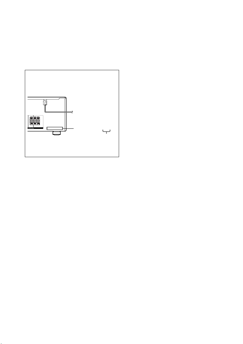
About area codes
The area code of the receiver you purchased is
shown on the lower portion of the rear panel (see
the illustration below).
RRL
+—+
—
L
CENTER SURROUND
Any differences in operation, according to the
area code, are clearly indicated in the text, for
example, “Models of area code AA only”.
Tip
The instructions in this manual describe the controls
on the receiver. You can also use the controls on the
supplied remote if they have the same or similar
names as those on the receiver. For details on the use
of your remote, see pages 37–40.
4-XXX-XXX-XX AA
Area code
Note for the supplied remote
For RM-U306A
(STR-DE495 only) The MULTI CH button on
the remote is not available.
GB
4
Page 5
1234 56789q;q
q
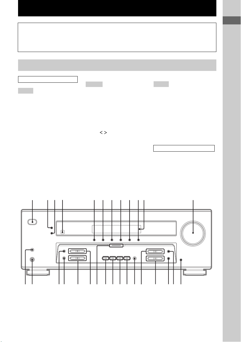
List of Button Locations and Reference Pages
How to use this page
Use this page to find the location of buttons
that are mentioned in the text.
Main unit
ALPHABETICAL ORDER
A – L
A.F.D. (button/indicator) wa
(23–25)
CD (STR-DE495 only) 9 (21)
CD/SACD (STR-DE595 only) 9
(21)
DIMMER 3 (22)
DISPLAY 2 (22, 32, 43)
Display qa (22)
DVD 7 (21)
ENTER qg (34, 36)
FM MODE wh (30)
INPUT MODE qd (21)
IR (receptor) 4 (37, 43)
M – O
MAIN MENU qf (16, 27, 28, 34,
35, 47)
MASTER VOLUME qs (20, 21,
41)
MD/TAPE 8 (21)
MEMORY wj (29, 31)
MENU +/– qh (16, 27, 28, 34, 35,
47)
MENU / qj (16, 27, 28, 34, 35,
47)
MOVIE (button/indicator) w; (24,
42)
MULTI CHANNEL DECODING
(indicator) (STR-DE595 only) wd
(21)
MULTI CH IN (STR-DE595 only)
qk (21)
MUSIC (button/indicator) ql
(24, 25, 42)
Illustration number
r
DISPLAY 2 (22, 32, 43)
Name of button/part Reference page
R R
P – Z
PHONES (jack) wk (22, 26, 42)
PRESET TUNING +/– wf (31, 46)
SPEAKERS (OFF/A/B/A+B)
(STR-DE595 only) wl (13, 22,
41)
TUNER FM/AM q; (21, 30, 31,
34)
TUNING +/– wg (30)
VIDEO 1 5 (21)
VIDEO 2 6 (21)
NUMBERS AND SYMBOLS
2CH (button/indicator) ws (23, 25,
28)
?/1 (power) 1 (15, 20, 28, 29, 36,
46)
List of Button Locations and Reference Pages
?/1
g
a
s
qdqfqgqhqjqkqlw;wawswdwfwgwhwjwkwl
GB
5
Page 6
Hooking Up the Components
Required cords
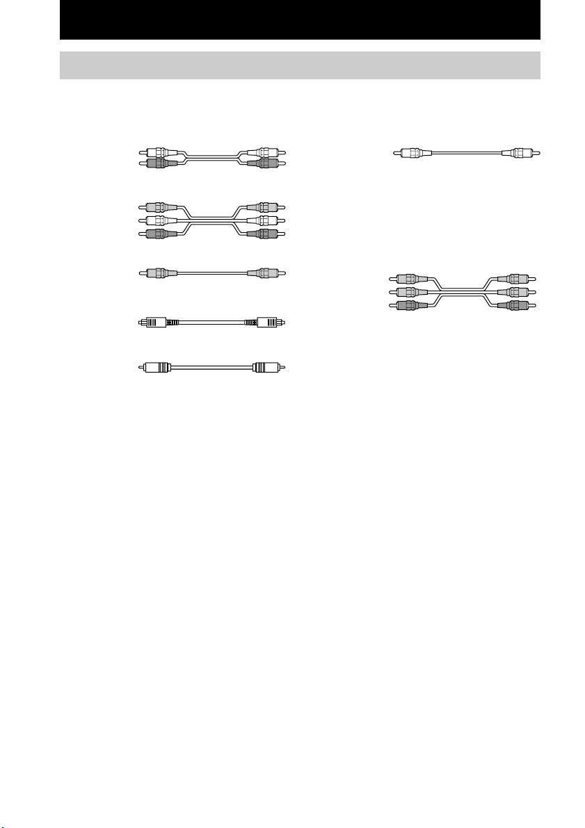
The following optional connection cords A – G are required when you hook up the components
(pages 8–11).
A Audio cord (not supplied)
White (L)
Red (R)
B Audio/video cord (not supplied)
Yellow (video)
White (L/audio)
Red (R/audio)
C Video cord (not supplied)
Yellow
D Optical digital cord (not supplied)
E Coaxial digital cord (not supplied)
F Monaural audio cord (not supplied)
Black
Tip
Audio cord A can be torn into two monaural audio
cords F.
G Component video cord (not supplied)
(STR-DE595 only, except for models of area
code CEL, CEK)
Green
Blue
Red
Before you get started
• Turn off the power to all components before making any connections.
• Do not connect the AC power cord until all of the connections are completed.
• Be sure to make connections firmly to avoid hum and noise.
• When connecting an audio/video cord, be sure to match the color-coded pins to the appropriate jacks on
the components: yellow (video) to yellow; white (left, audio) to white; and red (right, audio) to red.
• When you connect optical digital cords, insert the cord plugs straight in until they click into place.
• Do not bend or tie the optical digital cord.
GB
6
Page 7
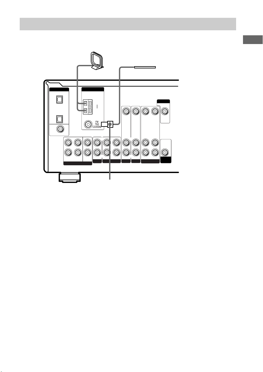
Antenna hookups
AM loop antenna
(supplied)
FM wire antenna
(supplied)
L
R
MULTI CH IN
ANTENNA
CENTER
SUB
WOOFER
AM
y
IN OUT
CD/SACD
LRL
VIDEO IN VIDEO IN VIDEO OUT VIDEO IN VIDEO OUT
L
R
AUDIO IN AUDIO IN
IN
DVDMD/TAPE
R
VIDEO 2
DIGITAL
OPTICAL
VIDEO 2
IN
CD/
SACD
IN
DVD IN
COAXIAL
FRONT SURROUND
*
* The shape of the connector varies depending on the area code.
Notes on antenna hookups
• To prevent noise pickup, keep the AM loop
antenna away from the receiver and other
components.
• Be sure to fully extend the FM wire antenna.
• After connecting the FM wire antenna, keep it
as horizontal as possible.
L
R
AUDIO OUT
AUDIO IN
VIDEO 1
MONITOR
AUDIO
OUT
SUB
WOOFER
Hooking Up the Components
GB
7
Page 8
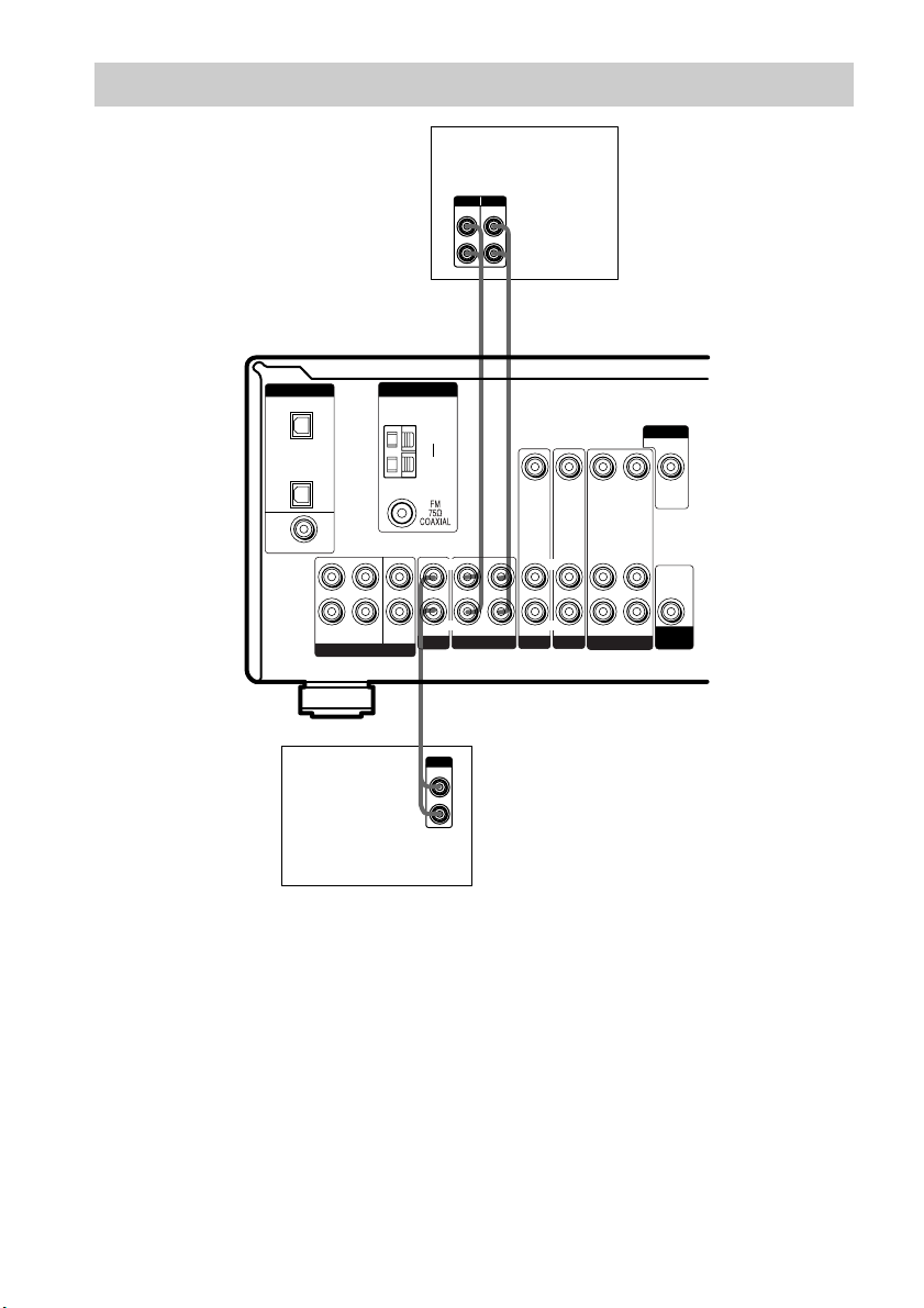
Audio component hookups
MD/Tape deck
INPUT OUTPUT
LINE
LINE
L
R
AA
ç
INOUT
ç
* STR-DE595 only.
DIGITAL
OPTICAL
VIDEO 2
IN
CD/
SACD
IN
DVD IN
COAXIAL
L
R
FRONT SURROUND
MULTI CH IN
CD or Super Audio
CD* player
ANTENNA
CENTER
SUB
WOOFER
AM
y
IN OUT
CD/SACD
A
OUTPUT
LINE
LRL
L
R
VIDEO IN VIDEO IN VIDEO OUT VIDEO IN VIDEO OUT
L
R
AUDIO IN AUDIO IN
IN
DVDMD/TAPE
R
VIDEO 2
AUDIO OUT
VIDEO 1
L
R
AUDIO IN
MONITOR
AUDIO
OUT
SUB
WOOFER
GB
8
Page 9
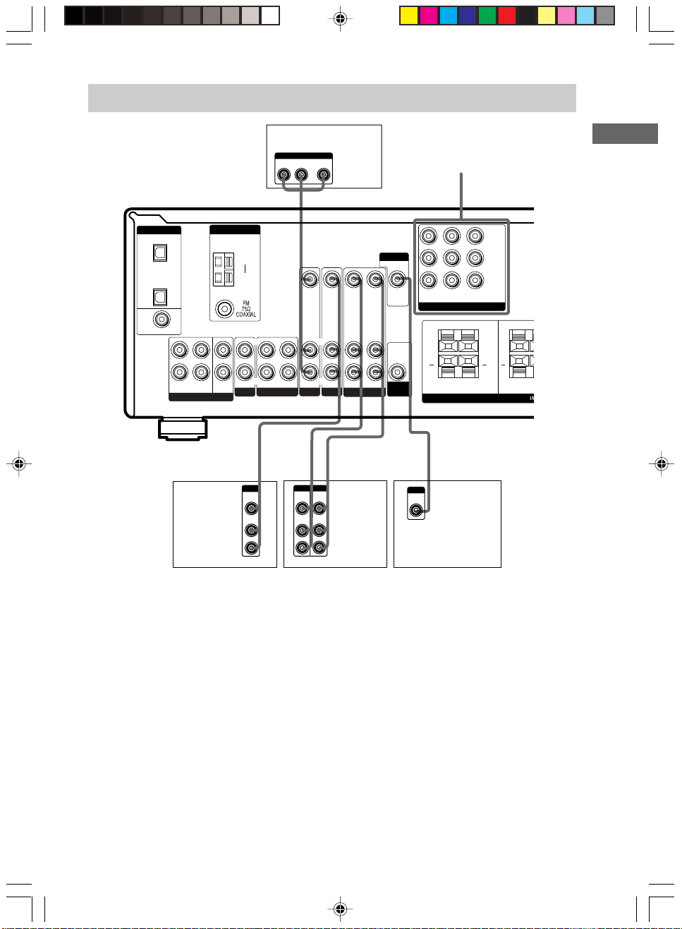
T
Video component hookups
DIGITAL
OPTICAL
VIDEO 2
IN
CD/
SACD
IN
DVD IN
COAXIAL
ANTENNA
L
CENTER
R
MULTI CH IN
SUB
WOOFER
FRONT SURROUND
Satellite
tuner or
VCR
AM
y
IN OUT
CD/SACD
Ç
IN
B
OUTPUT
VIDEO
OUT
AUDIO
OUT
LRL
L
R
DVD player
OUTPUT
AUDIO OUT VIDEO
L
OUT
R
B G
MONITOR
VIDEO IN VIDEO IN VIDEO OUT VIDEO IN VIDEO OUT
L
R
R
AUDIO IN AUDIO IN
IN
DVDMD/TAPE
Ç
BB
OUTPUTINPUT
VIDEO
VIDEO
OUT
IN
AUDIO
AUDIO
OUT
IN
VIDEO 2
Ç
L
R
L
R
AUDIO OUT
AUDIO IN
VIDEO 1
INOUT
VCR
AUDIO
OUT
SUB
WOOFER
COMPONENT VIDEO*
Y
P
B
/B—Y
P
R
DVD IN VIDEO 2INMONITOR
COMPONENT VIDEO
RRL
+ + +
FRONT B FRON
/R—Y
OUT
L
SPEAKERS
C
INPUT
VIDEO
IN
TV monitor
Hooking Up the Components
R
R
* STR-DE595 only, except for models of area code CEL, CEK.
Note on video component
hookups
You can connect your TV’s audio output jacks
to the VIDEO 2 AUDIO IN jacks on the
receiver and apply sound effects to the audio
from the TV. In this case, do not connect the
TV’s video output jack to the VIDEO 2
VIDEO IN jack on the receiver. If you are
connecting a separate satellite tuner, connect
both the audio and video output jacks to the
receiver as shown above.
STR-DE595/DE495 4-244-173-71(1) (GB, CS)
STR-DE595 only, except for models
of area code CEL, CEK
If you have a DVD player, TV or satellite tuner
with COMPONENT VIDEO (Y, B–Y, R–Y)
output jacks and a monitor with COMPONENT
VIDEO input jacks, use a component video
cord (not supplied) to connect to the receiver.
GB
9
Page 10
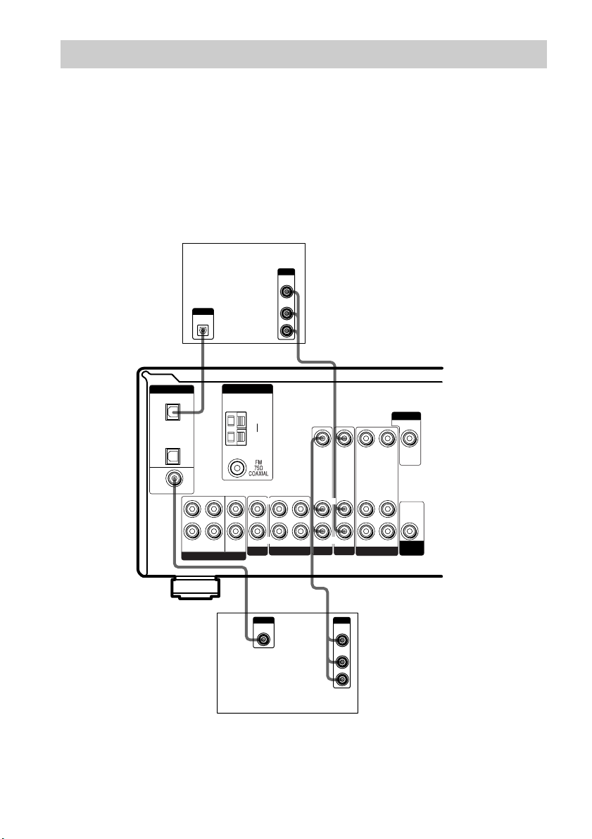
Digital component hookups
Connect the digital output jacks of your DVD player and satellite tuner (etc.) to the receiver’s digital
input jacks to bring the multi channel surround sound of a movie theater into your home. To fully
enjoy multi channel surround sound, five speakers (two front speakers, two surround speakers, and a
center speaker) and a sub woofer are required.
Notes
• All the OPTICAL and COAXIAL jacks are compatible with 96 kHz, 48 kHz, 44.1 kHz and 32 kHz sampling
frequencies.
• (STR-DE595 only) The sound is not output when you play a Super Audio CD on the Super Audio CD player
connected to the CD/SACD OPTICAL IN jack on this unit. Connect to the analog input jacks (CD/SACD IN
jacks). Refer to the operating instructions supplied with the Super Audio CD player.
DIGITAL
OPTICAL
VIDEO 2
IN
CD/
SACD
IN
DVD IN
COAXIAL
FRONT SURROUND
Satellite tuner or
DVD player*
OUTPUT
DIGITAL
OPTICAL
ANTENNA
AM
y
L
R
MULTI CH IN
CENTER
SUB
WOOFER
IN OUT
CD/SACD
LRL
E
OUTPUT
DIGITAL
COAXIAL
DVD player (etc.)*
OUTPUT
VIDEO
OUT
AUDIO
OUT
L
R
BD
VIDEO IN VIDEO IN VIDEO OUT VIDEO IN VIDEO OUT
L
R
AUDIO IN AUDIO IN
IN
DVDMD/TAPE
R
VIDEO 2
B
OUTPUT
VIDEO
OUT
AUDIO
OUT
AUDIO OUT
VIDEO 1
L
R
L
R
AUDIO IN
MONITOR
AUDIO
OUT
SUB
WOOFER
* Make either coaxial or optical connections. We recommend making coaxial connections instead of optical
connections.
GB
10
Page 11
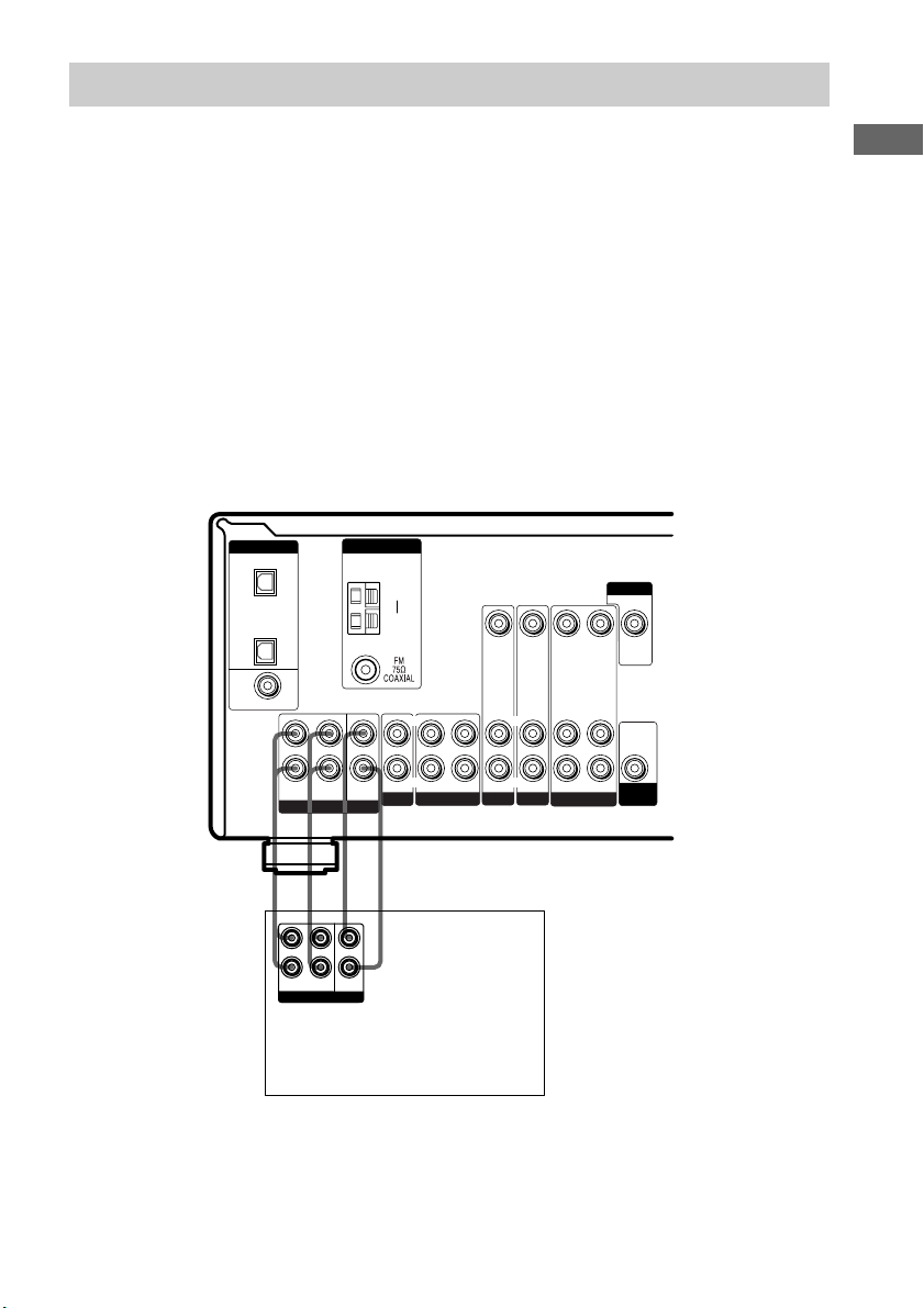
Multi channel input hookups
STR-DE595 only
Although this receiver incorporates a multi channel decoder, it is also equipped with multi channel
input jacks. These connections allow you to enjoy multi channel software encoded in formats other
than Dolby Digital and DTS. If your DVD player is equipped with multi channel output jacks, you
can connect them directly to the receiver to enjoy the sound of the DVD player’s multi channel
decoder. Alternatively, the multi channel input jacks can be used to connect an external multi channel
decoder.
To fully enjoy multi channel surround sound, five speakers (two front speakers, two surround
speakers, and a center speaker) and a sub woofer are required. Refer to the operating instructions
supplied with your DVD player, multi channel decoder, etc., for details on the multi channel
hookups.
Notes
• When using the connections described below, adjust the level of the surround speakers and sub woofer from the
DVD player or multi channel decoder.
• See page 13 for details on speaker system hookup.
Hooking Up the Components
L
R
MULTI CH IN
ANTENNA
CENTER
SUB
WOOFER
DIGITAL
OPTICAL
VIDEO 2
IN
CD/
SACD
IN
DVD IN
COAXIAL
FRONT SURROUND
AFAF
L
R
FRONT
SURROUND
MULTI CH OUT
CENTER
SUB
WOOFER
DVD player,
Multichannel decoder, etc.
AM
y
IN OUT
CD/SACD
LRL
VIDEO IN VIDEO IN VIDEO OUT VIDEO IN VIDEO OUT
L
R
R
AUDIO IN AUDIO IN
IN
DVDMD/TAPE
VIDEO 2
AUDIO OUT
VIDEO 1
L
R
AUDIO IN
MONITOR
AUDIO
OUT
SUB
WOOFER
11
GB
Page 12
Other hookups
Y
P
B
/B—Y
P
R
/R—Y
DVD IN VIDEO 2
MONITOR
OUT
IN
COMPONENT VIDEO
RRL
+
—
L
FRONT B FRONT A CENTER SURROUND
+—+
—
SPEAKERS
RRL
+—+
L
—
AC power cord
RRL
+
—
L
b
To a wall outlet
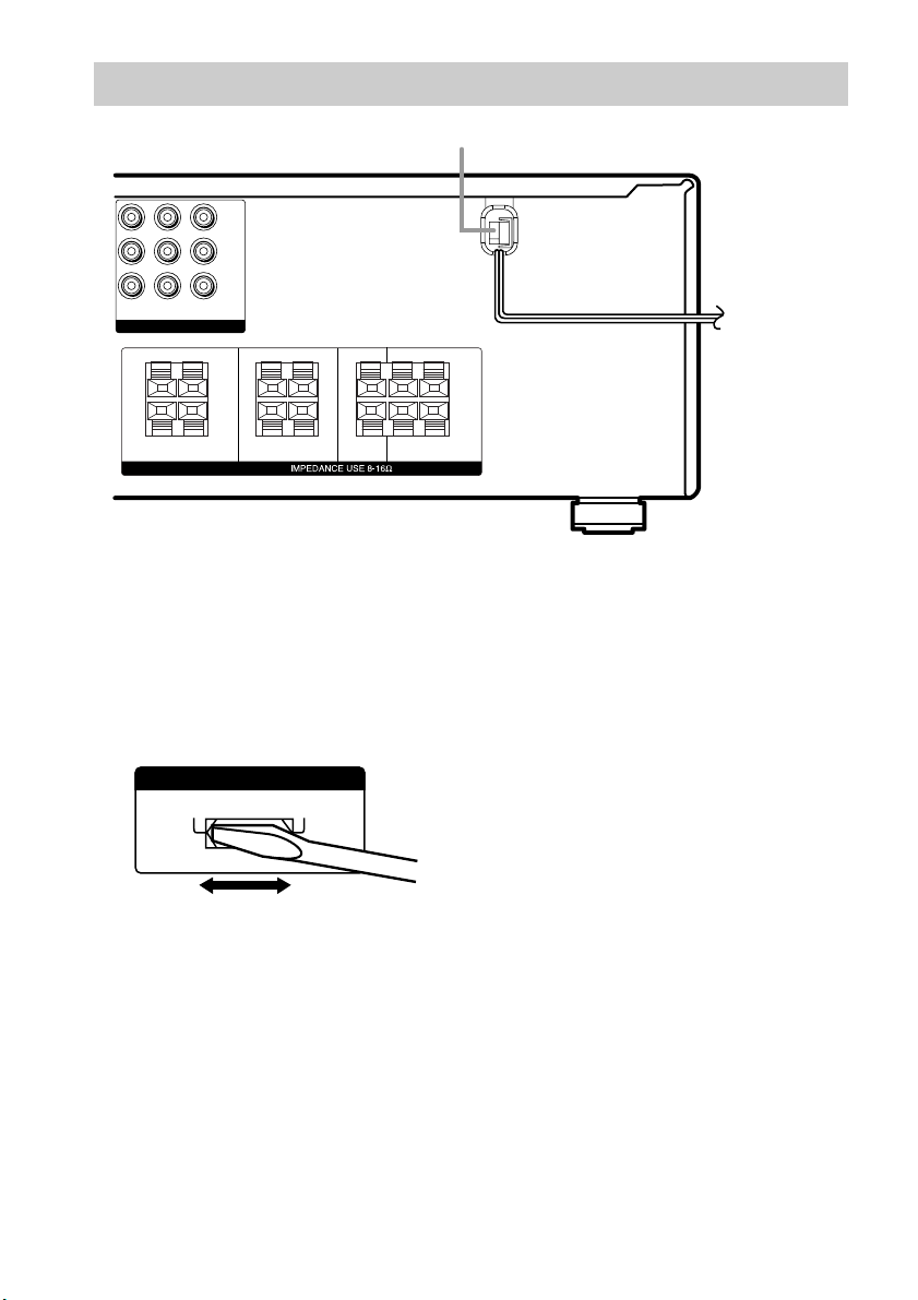
Setting the voltage selector
If your receiver has a voltage selector on the
rear panel, check that the voltage selector is set
to the local power supply voltage. If not, use a
screwdriver to set the selector to the correct
position before connecting the AC power cord
to a wall outlet.
VOLTAGE SELECTORVOLTAGE SELECTOR
120V
220V 240V
Connecting the AC power
cord
Before connecting the AC power cord of this
receiver to a wall outlet, connect the speaker
system to the receiver (page 13).
Connect the AC power cord(s) of your audio/
video components to a wall outlet.
12
GB
Page 13
Hooking Up and Setting Up the Speaker System
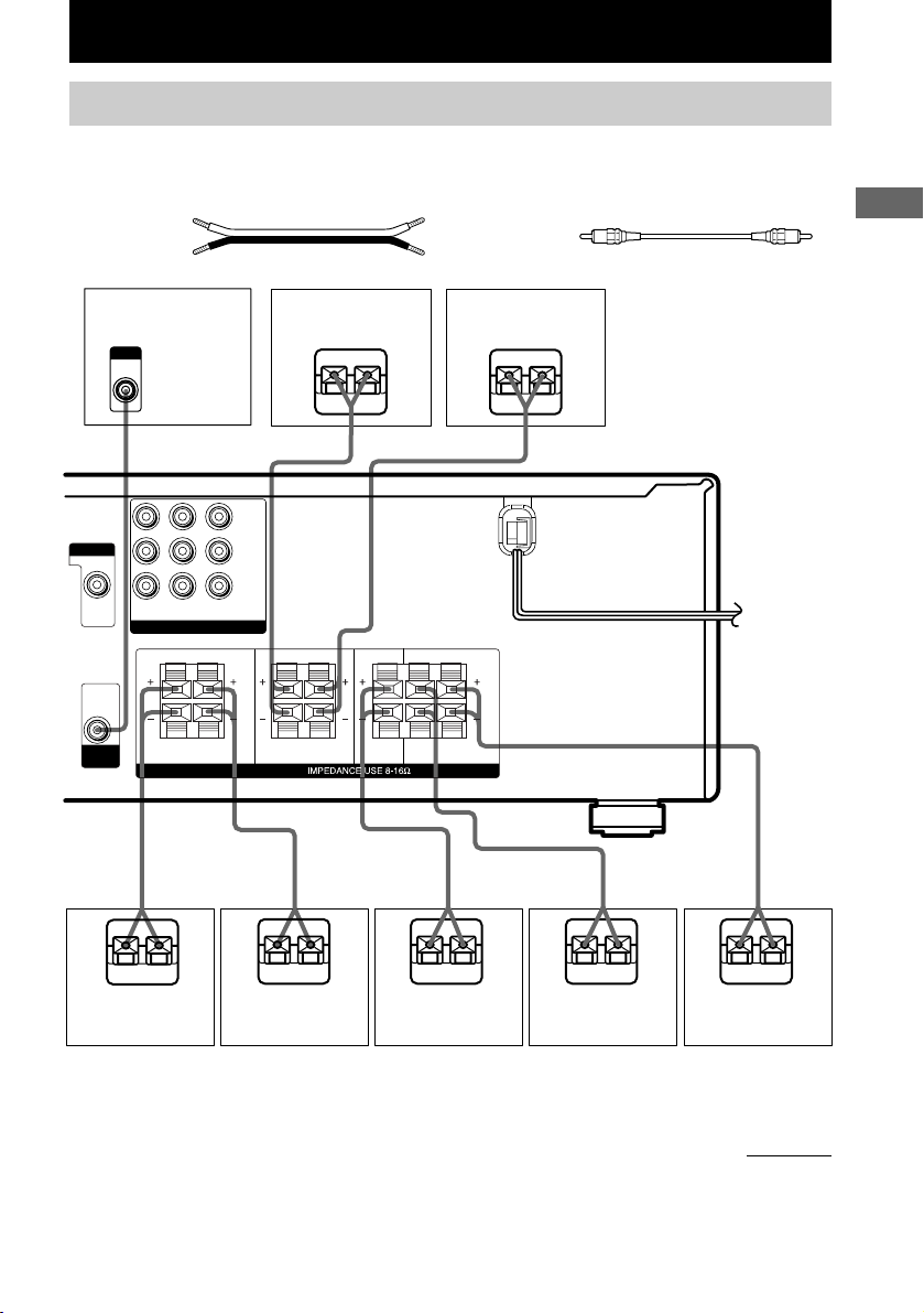
Speaker system hookups
Required cords
A Speaker cords (not supplied)
(+)
(–)
B Monaural audio cord (not supplied)
Black
Hooking Up and Setting Up the Speaker System
Active sub woofer
INPUT
AUDIO
IN
B
MONITOR
VIDEO OUT
DVD IN VIDEO 2INMONITOR
COMPONENT VIDEO
RRL
AUDIO
OUT
SUB
WOOFER
FRONT B FRONT A CENTER SURROUND
A
OUT
L
Front speaker A
(R)
Ee
A
Y
P
B/B—Y
P
R/R—Y
RRL
L
SPEAKERS
AA
RRL
L
Front speaker A
(L)
E
A
e
A
A
E
Front speaker B*
(R)
E
e
Front speaker B*
(L)
e
E
Center speaker
e
E
Surround speaker
(R)
e
E
Surround speaker
(L)
* (STR-DE595 only) If you have an additional front speaker system, connect them to the SPEAKERS FRONT B
terminals. You can select the front speakers you want to use with the SPEAKERS (OFF/A/B/A+B) button (page
22).
continued
e
13
GB
Page 14
Speaker system hookup (continued)
Notes
• Twist the stripped ends of the speaker cords about
10 mm (2/3 inch). Be sure to match the speaker
cord to the appropriate terminal on the components:
+ to + and – to –. If the cords are reversed, the
sound will be distorted and will lack bass.
• If you use speakers with low maximum input rating,
adjust the volume carefully to avoid excessive
output on the speakers.
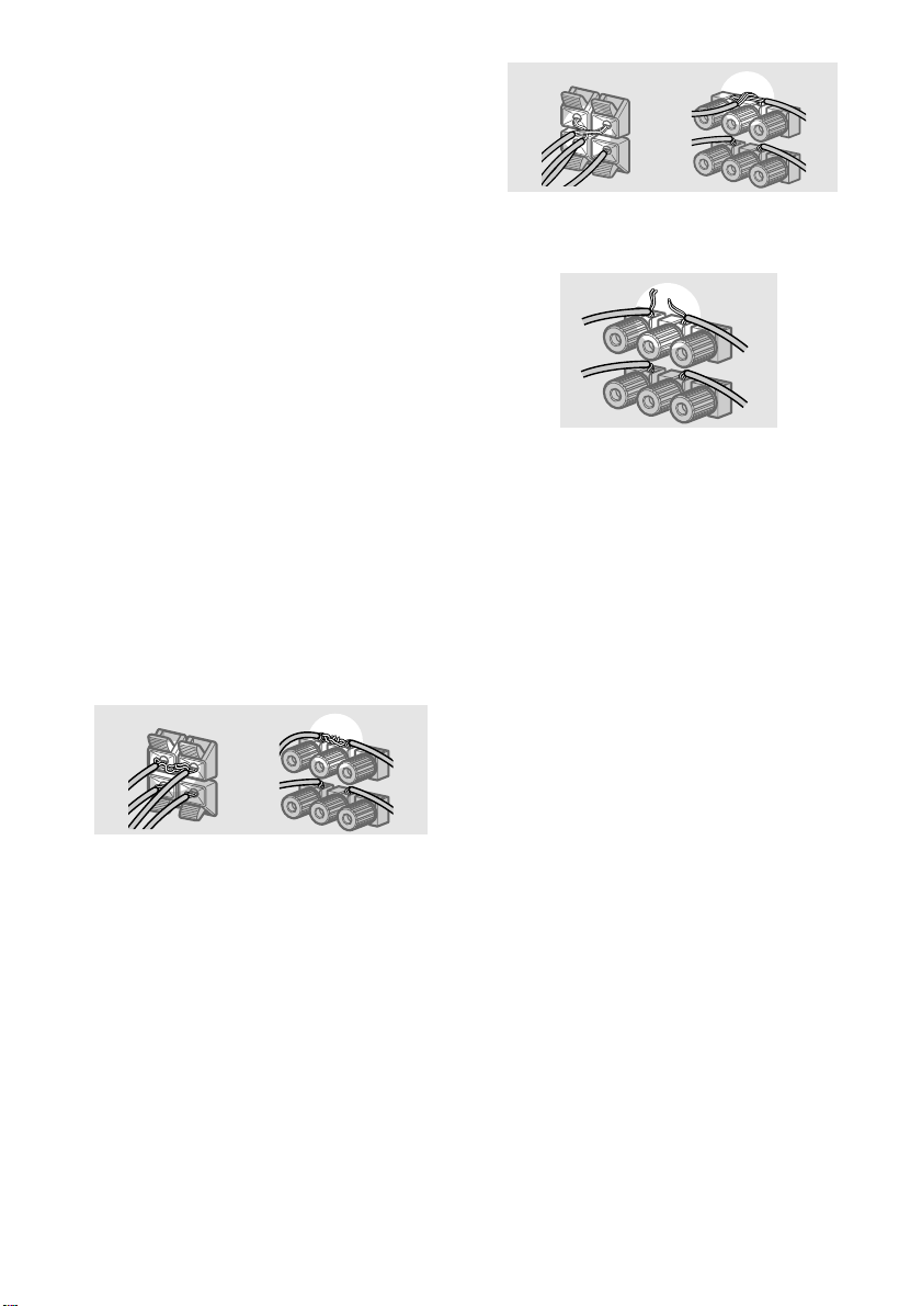
To avoid short-circuiting the
speakers
Short-circuiting of the speakers may damage
the receiver. To prevent this, make sure to take
the following precautions when connecting the
speakers.
Make sure the stripped ends of each
speaker cord does not touch another
speaker terminal, the stripped end of
another speaker cord, or the metal parts of
the receiver.
Examples of poor conditions of the
speaker cord
Stripped cords are touching each other
due to excessive removal of insulation.
Stripped cords are not fully attached and
are touching the rear panel of the receiver.
After connecting all the components,
speakers, and AC power cord, output
a test tone to check that all the
speakers are connected correctly.
For details on outputting a test tone,
see page 20.
If no sound is heard from a speaker while
outputting a test tone or a test tone is output
from a speaker other than the one whose name
is currently displayed on the receiver, the
speaker may be short-circuited. If this happens,
check the speaker connection again.
Stripped speaker cord is touching another
speaker terminal.
GB
14
To avoid damaging your
speakers
Make sure that you turn down the volume
before you turn off the receiver. When you turn
on the receiver, the volume remains at the level
you turn off the receiver.
Page 15
45°
90°
20°
A A
B
CC
Performing initial setup
operations
Once you have hooked up the speakers and
turned on the power, clear the receiver’s
memory. Then specify the speaker parameters
(size, position, etc.) and perform any other
initial setup operations necessary for your
system.
Tip
To check the audio output during settings (to set up
while outputting the sound), check the connection
(page 20).
Clearing the receiver’s
memory
Before using your receiver for the first time, or
when you want to clear the receiver’s memory,
do the following.
1 Turn off the receiver.
2 Hold down ?/1 for 5 seconds.
“INITIAL” appears in the display.
The following are reset to their factory
settings.
• All settings in the SET UP, LEVEL and
TONE menus.
• The sound field memorized for each
function and preset station.
• All sound field parameters.
• All preset stations.
• All index names for input selectors and
preset stations.
• The master volume is set to
“VOL MIN”.
Performing initial setup
operations
Before using your receiver for the first time,
adjust SET UP parameters so that the receiver
correspond to your system. For the adjustable
parameters, see the table on page 47. See pages
15–20 for speaker settings and pages 35–36 for
other settings.
Multi channel surround
setup
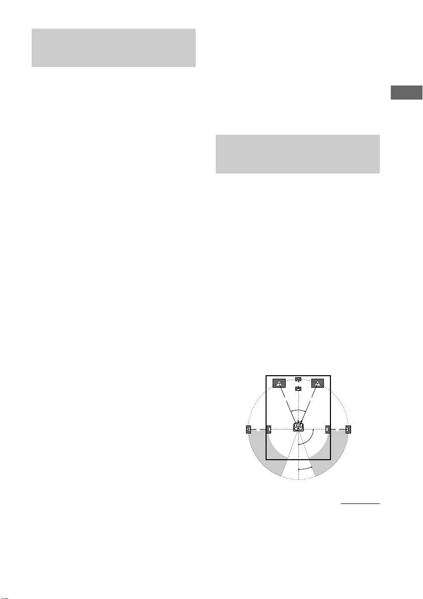
For the best possible surround sound, all
speakers should be the same distance from the
listening position (A).
However, the receiver lets you place the center
speaker up to 1.5 meters (5 feet) closer (B)
and the surround speakers up to 4.5 meters
(15 feet) closer (C) to the listening position.
The front speakers can be placed from 1.0 to
7.0 meters (3 to 23 feet) from the listening
position (A).
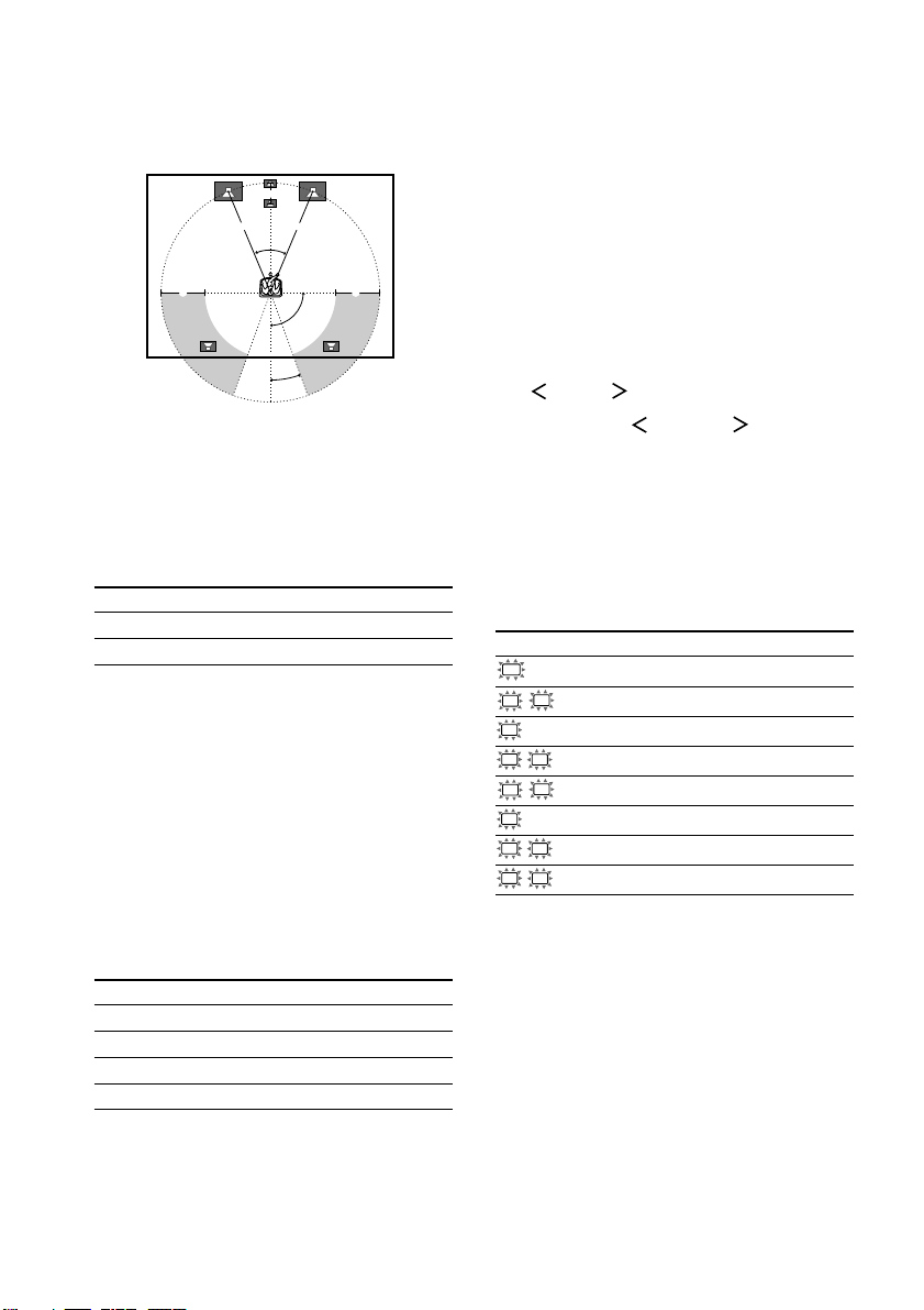
You can place the surround speakers either
behind you or to the side, depending on the
shape of your room (etc.). However, we
recommend that you place the surround
speakers behind you.
When placing surround speakers to your side
(long room)
Hooking Up and Setting Up the Speaker System
continued
15
GB
Page 16
Multi channel surround setup
(continued)
When placing surround speakers behind you
(wide room)
B
A A
45°
90°
CC
Tip
The setting for Micro Satellite Speaker (MICRO SP.)
has been programmed to optimize the sound balance.
If you use Sony’s Micro Satellite Speakers, select
“MICRO SP.”.
Caution
When you use Micro Satellite Speakers and the
speaker size is set to “LARGE”, you may not obtain
the correct soundstage. The speaker may also be
damaged at high volume position.
Specifying the speaker
parameters
20°
Note
Do not place the center speaker further away from the
listening position than the front speakers.
Normal Speaker and Micro
Satellite Speaker
If you are using Select
Normal Speakers NORM. SP.
Micro Satellite Speakers MICRO SP.
The speaker size and the sub woofer selection
has been preset to “NORM. SP.”. You can
adjust the speaker size and sub woofer
selection when you select “NORM. SP.” (page
17).
To select “MICRO SP.”, turn off the power,
then turn on again while pressing MAIN
MENU. (To reset to “NORM. SP.”, do the
same procedure.)
When you select “MICRO SP.”, the speaker
size and sub woofer selection has been
configurated as follows:
Speaker Settings
FRONT SMALL
CENTER SMALL
SURROUND SMALL
SUB WOOFER YES
You cannot change the configuration if you select
“MICRO SP.”.
1 Press MAIN MENU repeatedly to select
“ SET UP ”.
2 Press MENU or MENU to select
the parameter you want to adjust.
3 Press MENU + or MENU – to select the
setting you want.
The setting is entered automatically.
4 Repeat steps 2 and 3 until you have set
all of the parameters that follow.
Initial settings
Parameter Initial setting
SW
(SUB WOOFER) S.W. XXX YES*
L
R (FRONT) XXXXX LARGE*
C
(CENTER) XXXXX LARGE*
SL
SR (SURROUND) XXXXX LARGE*
L
R DIST. X.X m (XX ft.)** 3.0 m (10 ft.)**
C
DIST. X.X m (XX ft.)** 3.0 m (10 ft.)**
SL
SR DIST. X.X m (XX ft.)** 3.0 m (10 ft.)**
SL
SR PL. XXXX LOW
* You can set this parameter only when you select
“NORM. SP.”.
** The default unit for models of area code U, CA is
“ft.”.
The default unit for models of other area code is
“m”.
16
GB
Page 17
x Sub woofer selection (SW S.W. XXX)
• If you connect a sub woofer, select “YES”.
• If you do not connect a sub woofer, select
“NO”. This activates the bass redirection
circuitry and outputs the LFE signals from other
speakers.
• In order to take full advantage of the Dolby
Digital bass redirection circuitry, we
recommend that you set the cut off frequency
on the sub woofer as high as possible.
x Front speaker size (L R XXXXX)
• If you connect large speakers that will
effectively reproduce bass frequencies, select
“LARGE”. Normally, select “LARGE”.
• If the sound is distorted, or you feel a lack of
surround effects when using multi channel
surround sound, select “SMALL” to activate
the bass redirection circuitry and output the
front channel bass frequencies from the sub
woofer.
• When the front speakers are set to “SMALL”,
the center and surround speakers are also
automatically set to “SMALL” (unless
previously set to “NO”).
• When the sub woofer is set to “NO”, the front
speakers are automatically set to “LARGE” and
you cannot change this setting.
x Surround speaker size (SL
SR
XXXXX)
• If you connect large speakers that will
effectively reproduce bass frequencies, select
“LARGE”. Normally, select “LARGE”.
However, if the front speakers are set to
“SMALL”, you cannot set the surround
speakers to “LARGE”.
• If the sound is distorted, or you feel a lack of
surround effects when using multi channel
surround sound, select “SMALL” to activate
the bass redirection circuitry and output the
surround channel bass frequencies from the sub
woofer or other “LARGE” speakers.
• If you do not connect surround speakers, select
Tip
*1–*3 correspond to the following Dolby Pro Logic
modes
*1 NORMAL
*2 PHANTOM
*3 3 STEREO
“NO”.*
3
continued
Hooking Up and Setting Up the Speaker System
x Center speaker size (C XXXXX)
• If you connect a large speaker that will
effectively reproduce bass frequencies, select
“LARGE”. Normally, select “LARGE”.
However, if the front speakers are set to
“SMALL”, you cannot set the center speaker to
“LARGE”.
• If the sound is distorted, or you feel a lack of
surround effects when using multi channel
surround sound, select “SMALL” to activate
the bass redirection circuitry and output the
center channel bass frequencies from the front
speakers (if set to “LARGE”) or sub woofer.*
• If you do not connect a center speaker, select
“NO”. The sound of the center channel will be
output from the front speakers.*
2
1
GB
17
Page 18

Multi channel surround setup
(continued)
Tip
Internally, the LARGE and SMALL settings for each
speaker determine whether the internal sound
processor will cut the bass signal from that channel.
When the bass is cut from a channel, the bass
redirection circuitry sends the corresponding bass
frequencies to the sub woofer or other “LARGE”
speakers.
However, since bass sounds have a certain amount of
directionality, it is best not to cut them, if possible.
Therefore, even when using small speakers, you can
set them to “LARGE” if you want to output the bass
frequencies from that speaker. On the other hand, if
you are using a large speaker, but prefer not to have
bass frequencies output from that speaker, set it to
“SMALL”.
If the overall sound level is lower than you prefer, set
all speakers to “LARGE”. If there is not enough bass,
you can use the BASS parameter in the TONE menu
to boost the bass levels. To adjust the bass, see page
28.
x Front speaker distance (L R DIST.
X.X m (XX ft.))
Set the distance from your listening position to
the front speakers (A on page 15).
x Center speaker distance (C DIST. X.X
m (XX ft.))
Set the distance from your listening position to
the center speaker. Center speaker distance
should be set from a distance equal to the front
speaker distance (A on page 15) to a distance
1.5 meters (5 feet) closer to your listening
position (B on page 15).
Tip
The receiver allows you to input the speaker position
in terms of distance. However, it is not possible to set
the center speaker further than the front speakers.
Also, the center speaker cannot be set more than
1.5 meters (5 feet) closer than the front speakers.
Likewise, the surround speakers can not be set further
away from the listening position than the front
speakers. And they can be no more than 4.5 meters
(15 feet) closer.
This is because incorrect speaker placement is not
conducive to enjoy surround sound.
Please note that, setting the speaker distance closer
than the actual location of the speakers will cause a
delay in the output of the sound from that speaker. In
other words, the speaker will sound like it is further
away.
For example, setting the center speaker distance
1~2 m (3~6 feet) closer than the actual speaker
position will create a fairly realistic sensation of being
“inside” the screen. If you cannot obtain a satisfactory
surround effect because the surround speakers are too
close, setting the surround speaker distance closer
(shorter) than the actual distance will create a larger
sound stage.
Adjusting these parameter while listening to the
sound often results in much better surround sound.
Give it a try!
x Surround speaker distance (SL
DIST. X.X m (XX ft.))
Set the distance from your listening position to
the surround speakers. Surround speaker
distance should be set from a distance equal to
the front speaker distance (A on page 15) to a
distance 4.5 meters (15 feet) closer to your
listening position (C on page 15).
GB
18
SR
Page 19
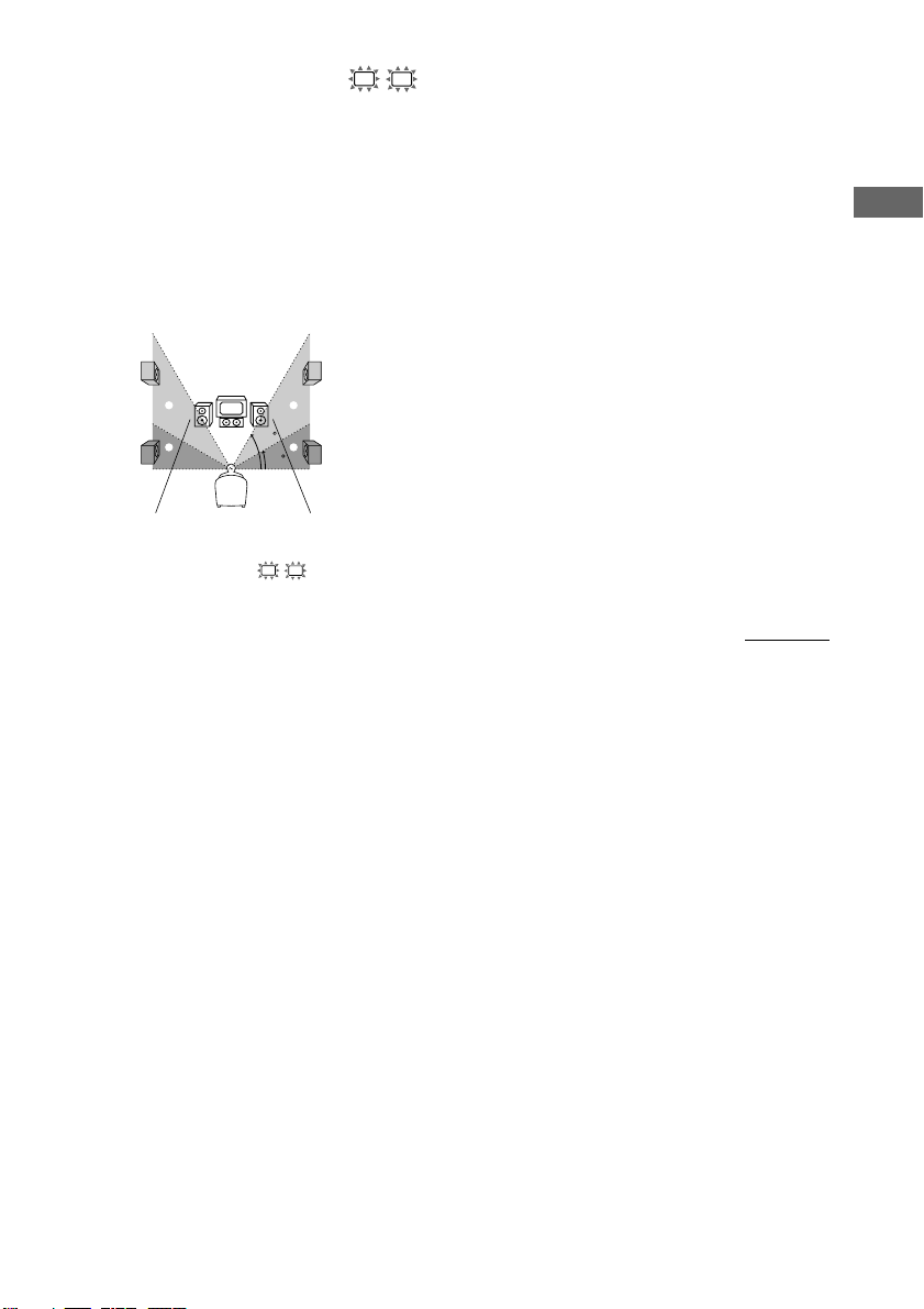
x Surround speaker placement (SL
SR
PL. XXXX)*
This parameter lets you specify the height of
your surround speakers for proper
implementation of the Digital Cinema Sound
surround modes. Refer to the illustration below.
• Select “PL. LOW” if the location of your
surround speakers corresponds to section A.
• Select “PL. HIGH” if the location of your
surround speakers corresponds to section B.
B
A
B
60
A
30
* These parameters are not available when
“Surround speaker size (SL SR)” is set to “NO”.
Tip
The surround speaker placement parameter is
designed specifically for implementation of the
Digital Cinema Sound modes with virtual elements.
With the Digital Cinema Sound modes, speaker
placement is not as critical as other modes. All modes
with virtual elements were designed under the
premise that the surround speaker would be located
behind the listening position, but presentation remains
fairly consistent even with the surround speakers
positioned at a rather wide angle. However, if the
speakers are pointing towards the listener from the
immediate left and right of the listening position, the
sound fields with virtual elements will not be as
effective.
Nevertheless, each listening environment has many
variables, like wall reflections.
Therefore, we recommend that you playback multi
channel surround encoded software and listen to the
effect each setting has on your listening environment.
Choose the setting that provides a good sense of
spaciousness and that best succeeds in forming a
cohesive space between the surround sound from the
surround speakers and the sound of the front
speakers. If you are not sure which sounds best, select
“PL. LOW” and then use the speaker distance
parameter and speaker level adjustments to obtain
proper balance.
continued
Hooking Up and Setting Up the Speaker System
19
GB
Page 20

Multi channel surround setup
(continued)
Checking the connections
Adjusting the speaker level
Use the remote while seated in your listening
position to adjust the level of each speaker.
Note
The receiver incorporates a new test tone with a
frequency centered at 800 Hz for easier speaker level
adjustment.
1 Press ?/1 on the remote to turn on the
receiver.
2 Press TEST TONE on the remote.
“T. TONE” appears in the display and you
will hear the test tone from each speaker in
sequence.
Front (left) t Center t Front (right) t
Surround (right) t Surround (left) t
Sub woofer
3 Adjust the speaker level and balance
using the LEVEL menu so that the level
of the test tone sounds the same from
each speaker.
For details on the LEVEL menu, see page
27.
While adjusting, the test tone is output from
the speaker whose adjustment is performed.
4 Press TEST TONE again to turn off the
test tone.
Tip
You can adjust the level of all speakers at the same
time. Press MASTER VOL +/– on the remote or turn
MASTER VOLUME on the receiver.
After connecting all of your components to the
receiver, do the following to verify that the
connections were made correctly.
1 Press ?/1 to turn on the receiver.
2 Turn on the component that you
connected (e.g., CD player or tape
deck).
3 Press the input selector button
(e.g., CD/SACD (STR-DE595 only) / CD
(STR-DE495 only) or MD/TAPE) to
select the component (program
source).
4 Start playing.
If you do not obtain normal sound output after
performing this procedure, see
“Troubleshooting” on page 41 and take the
appropriate measures to correct the problem.
Notes
• (STR-DE595 only) The test tone cannot be output
when the receiver is set to MULTI CH IN.
• The adjusted value are shown in the display during
adjustment.
• Although these adjustments can also be made via
the front panel using the LEVEL menu (when the
test tone is output, the receiver switches to the
LEVEL menu automatically), we recommend you
follow the procedure described above and adjust the
speaker levels from your listening position using the
remote.
GB
20
Page 21
Basic Operations
Selecting the component
Input Selector buttons
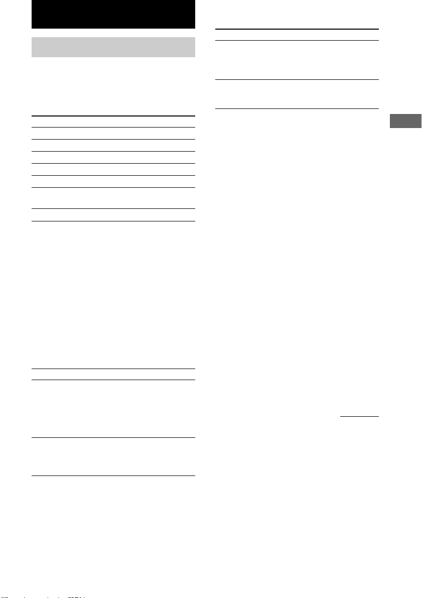
Press the input selector button to select the
component you want to use.
To select Press
VCR VIDEO 1 or VIDEO 2
Satellite tuner VIDEO 2
DVD player DVD
MD or Tape deck MD/TAPE
CD player CD (STR-DE495 only)
CD or Super Audio CD/SACD
CD player (STR-DE595 only)
Built in tuner TUNER FM/AM
After turning on the component you selected,
select the component and play the program
source.
• After selecting VCR or DVD player, turn on the
TV and set the TV’s video input to match the
component you selected.
INPUT MODE
Press INPUT MODE to select the input mode
for your digital components.
Each time you press the button, the input mode
of the currently selected component switches.
Select To
AUTO IN Give priority to digital
signals when there are both
digital and analog
connections. If there are no
digital signals, analog is
selected.
COAX IN Specify the digital audio
signals input to the
DIGITAL COAXIAL input
jacks.
Select To
OPT IN Specify the digital audio
signals input to the
DIGITAL OPTICAL input
jacks.
ANALOG Specify the analog audio
signals input to the AUDIO
IN (L/R) jacks.
Note
When the 96 kHz digital signal is input, the tone,
sound field and surround effects do not function.
MULTI CH IN
(STR-DE595 only)
Press MULTI CH IN to enjoy the audio source
connected to the MULTI CH IN jacks. You can
adjust balance and level of all the speakers. When
this function is on, the tone and surround effects
are turned off.
MULTI CHANNEL DECODING
indicator
(STR-DE595 only)
This indicator lights up when the unit is
decoding signals recorded in a multi channel
format.
MUTING
Press MUTING on the remote to mute the
sound. Press again to cancel the muting
function. The muting function is also canceled
when you turn the power on or turn the
MASTER VOLUME to turn the volume up.
continued
Basic Operations
21
GB
Page 22

Selecting the component
(continued)
Changing the display
PHONES
Use to connect headphones.
• When the headphones are connected, speaker
output is automatically canceled and “SP”
(STR-DE495 only) or “SP A” and “SP B”
(STR-DE595 only) do not light up in the
display.
SPEAKERS (OFF/A/B/A+B)
(STR-DE595 only)
Press SPEAKERS (OFF/A/B/A+B) to output
the sound from the speakers connected to the
SPEAKERS FRONT terminals.
Each time you press the button, the display will
light up cyclically as follows:
SP A t SP B t SP A and SP B t
No display*
To drive Select
Speaker System A SP A (default setting)
(Connected to the
SPEAKERS FRONT A
terminals)
Speaker System B SP B
(Connected to the
SPEAKERS FRONT B
terminals)
Both Speaker System SP A and SP B
A and B
(Connected to the
SPEAKERS FRONT A
and B terminals)
DIMMER
Press DIMMER repeatedly to adjust the
brightness of the display (3 steps).
However, when you press any button, the
display becomes the brightest setting
temporary.
DISPLAY
Each time you press DISPLAY, the display
changes cyclically as follows:
Index name of the component* t Selected
component t Sound field applied to the
program source
When the tuner is selected
Index name of the preset station* or program
station name** t Frequency t Program type
indication** t Radio text** t Current
time** t Sound field applied to the band or
the preset station
* Index name appears only when you have assigned
one to the component or preset station (page 34).
Index name does not appear when only blank
spaces have been entered, or it is the same as the
input selector.
** During RDS reception only. (Models of area code
CEL, CEK only. See page 32.)
* If you do not want to drive Speaker System A and
B, press SPEAKERS (OFF/A/B/A+B) until “SP A”
and “SP B” do not light up in the display (no
display).
GB
22
Page 23

Enjoying Surround Sound
You can take advantage of surround sound
simply by selecting one of the receiver’s preprogrammed sound fields. They bring the
exciting and powerful sound of movie theaters
and concert halls into your home. You can also
customize the sound fields to obtain the sound
you want by changing the surround parameter.
To fully enjoy surround sound, you must
register the number and location of your
speakers. See “Multi channel surround setup”
starting from page 15 to set the speaker
parameters before enjoying surround sound.
Using only the front
speakers (2 Channel Stereo)
Press 2CH.
The 2CH indicator lights up and “2CH ST.”
appears in the display.
This mode outputs the sound from the front left
and right speakers only. Standard 2 channel
(stereo) sources completely bypass the sound
field processing. Multi channel surround
formats are downmixed to 2 channel.
Notes
• No sound is output from the sub woofer when
“2CH ST.” is selected. To listen to 2 channel
(stereo) sources using the front left and right
speakers and a sub woofer, press A.F.D. repeatedly
to select “A.F.D. AUTO”.
• When you select “Micro Satellite Speaker” (page
16), internal sound processor will automatically
redirect bass sound to sub woofer. If you want to
listen to two channel (stereo) sources under this
setting, we recommend that you choose “A.F.D.
AUTO” mode so that you can take advantage of
your sub woofer to obtain the correct bass signal.
Enjoying higher fidelity
sound
The Auto Format Direct (A.F.D.) mode allows
you to select the decoding mode you want for
your audio sound.
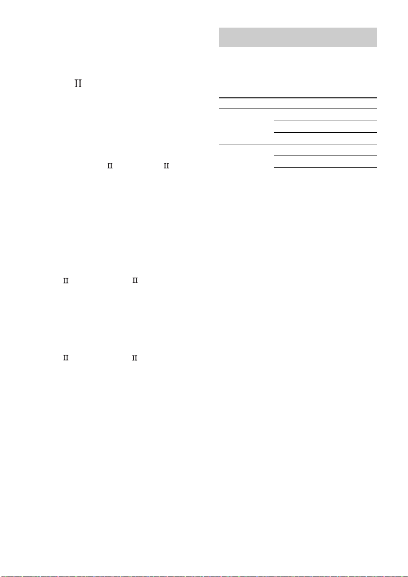
Mode Decoding Mode
A.F.D. AUTO As encoded
DOLBY PL Dolby Pro Logic
PLII MOV
PLII MUS
Decoding the input audio
signal automatically
Press A.F.D. repeatedly to select “A.F.D.
AUTO”.
The A.F.D. indicator lights up.
This mode automatically detects the type of
audio signal being input (Dolby Digital, DTS,
or standard 2 channel stereo) and performs the
proper decoding if necessary. This mode
presents the sound as it was recorded/encoded,
without adding any effects (e.g. reverberation).
However, if there are no low frequency signals
(Dolby Digital LFE, etc.) it will generate a low
frequency signal for output to the sub woofer.
Dolby Pro Logic II
continued
Enjoying Surround Sound
23
GB
Page 24
Enjoying higher fidelity sound
(continued)
Selecting a sound field
Enjoying stereo sound in
multi channel (Dolby Pro
Logic )
This receiver incorporates with Dolby Pro
Logic II which has movie mode and music
mode, and the receiver can reproduce the 2
channel sound in 5.1 channel through Dolby
Pro Logic II.
Press A.F.D. repeatedly to select
“DOLBY PL”, “PL MOV” or “PL MUS”.
The A.F.D. indicator lights up and the selected
type of decoding is indicated in the display.
x DOLBY PL (Dolby Pro Logic)
Performs the Pro Logic decoding. Software
with multi channel surround audio signals is
played back according to the way it was
recorded. Software with 2 channel audio
signals is decoded with Dolby Pro Logic to
create surround effects (4 channels).
x PL MOV (Pro Logic Movie)
Performs the Pro Logic II movie mode
decoding. This setting is ideal for the movies
encoded in Dolby Surround. Besides, this mode
can reproduce the sound in 5.1 channel when
watching the videos of old movies or in the
dubbed language.
x PL MUS (Pro Logic Music)
Performs the Pro Logic II music mode decoding.
This setting is ideal for the normal stereo
sources, such as CDs.
Note
Dolby Pro Logic and Dolby Pro Logic II decoding
does not function for DTS format signals.
You can enjoy surround sound simply by
selecting one of the pre-programmed sound
fields according to the program you want to
listen to.
Press To select
MOVIE C.ST.EX A DCS *
C.ST.EX B DCS *
C.ST.EX C DCS *
MUSIC HALL
JAZZ
CONCERT
* Sound field with DCS mark use DCS technology.
About DCS (Digital Cinema Sound)
In collaboration with Sony Pictures
Entertainment, Sony measured the sound
environment of their studios and integrated the
data of the measurement and Sony’s own DSP
(Digital Signal Processor) technology to
develop “Digital Cinema Sound”. In a home
theater, “Digital Cinema Sound” simulates an
ideal movie theater sound environment based
on the preference of the movie director.
Enjoying movies with Cinema
Studio EX
Cinema Studio EX is ideal for enjoying the
movie software encoded with multi channel
format, such as the Dolby Digital DVD. This
mode reproduces the sound characteristics of
Sony Pictures Entertainment’s studios.
Press MOVIE repeatedly to select
“C.ST.EX A”, “C.ST.EX B” or “C.ST.EX C”.
The MOVIE indicator lights up and the
selected sound field is indicated in the display.
24
GB
Page 25
x C.ST.EX A (Cinema Studio EX A)
Reproduces the sound characteristics of the
Sony Pictures Entertainment “Cary Grant
Theater” cinema production studio. This is a
standard mode, great for watching most any
type of movie.
x C.ST.EX B (Cinema Studio EX B)
Reproduces the sound characteristics of the
Sony Pictures Entertainment “Kim Novak
Theater” cinema production studio. This mode
is ideal for watching science-fiction or action
movies with lots of sound effects.
x C.ST.EX C (Cinema Studio EX C)
Reproduces the sound characteristics of the
Sony Pictures Entertainment scoring stage.
This mode is ideal for watching musicals or
classic films where music is featured in the
soundtrack.
About Cinema Studio EX
Cinema Studio EX consists of the following
three elements.
• Virtual Multi Dimension
Creates 5 sets of virtual speakers
surrounding the listener from a single pair of
actual surround speakers.
• Screen Depth Matching
In a movie theater, sound seems to come
from inside the image reflected on the movie
screen. This element creates the same
sensation in your listening room by shifting
the sound of the front speakers “into” the
screen.
• Cinema Studio Reverberation
Reproduces the reverberations peculiar to a
movie theater.
Cinema Studio EX is the integrated mode
which operates these elements simultaneously.
Notes
• The effects provided by the virtual speakers may
cause increased noise in the playback signal.
• When listening with sound fields that employ the
virtual speakers, you will not be able to hear any
sound coming directly from the surround speakers.
Selecting other sound fields
Press MUSIC repeatedly to select the
sound field you want.
The MUSIC indicator lights up and the current
sound field is indicated in the display.
x HALL
Reproduces the acoustics of a rectangular
concert hall.
x JAZZ (Jazz Club)
Reproduces the acoustics of a jazz club.
Enjoying Surround Sound
x CONCERT (Live Concert)
Reproduces the acoustics of a 300-seat live
concert
To turn the surround effect off
Press A.F.D. repeatedly to select “A.F.D.
AUTO” or press 2CH.
Tips
• The receiver lets you apply the last selected sound
field to a program source whenever it is selected
(Sound Field Link). For example, if you listen to
CD with “JAZZ” as the sound field, change to a
different program source, then return to CD,
“JAZZ” will be applied again.
• You can identify the encoding format of DVD
software, etc. by looking at the logo on the
package.
– : Dolby Digital discs
– : Dolby Surround encoded
programs
– : DTS Digital Surround encoded programs
• When sound signals with a sampling frequency of
96 kHz are input, the sound signals are output in
stereo automatically, and the sound field is turned
off.
25
GB
Page 26
Understanding the multi channel surround displays
1234 5 6 7 8
aa
DIGITALSP BSP ASP PRO LOGIC II
LCR
SW
LFE
SL SR
S
qdqf
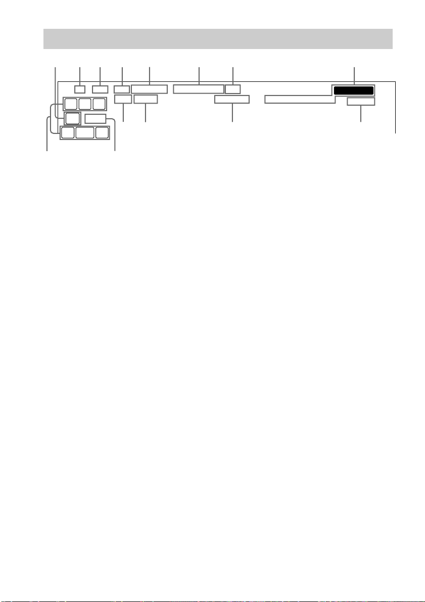
1 SW: Lights up when sub woofer selection is
set to “YES” (page 17) and the audio signal is
output from the SUB WOOFER jacks.
2 SP*: (STR-DE495 only) Lights up when you
turn on the receiver.
3 SP A*: (STR-DE595 only) Lights up when
you select to drive Speaker System A.
4 SP B*: (STR-DE595 only) Lights up when
you select to drive Speaker System B.
* Does not light up when you connect
headphones to the PHONES jack.
5 ; DIGITAL: Lights up when the receiver is
decoding signals recorded in the Dolby
Digital format.
6 ; PRO LOGIC II: “; PRO LOGIC”
lights up when the receiver applies Pro Logic
processing to 2 channel signals in order to
output the center and surround channel
signals. “; PRO LOGIC II” lights up when
Pro Logic II processing (“PLII MOV” or
“PLII MUS”) is applied (page 24). However,
both indicators do not light up if the center
and surround speakers are set to “NO”, and
“A.F.D. AUTO” or “DOLBY PL” is selected.
Note
Dolby Pro Logic and Dolby Pro Logic II
decoding does not function for DTS format
signals.
DTS
STEREOD.RANGECOAXOPT MONO RDS
MEMORY
SLEEP
90qaqs
7 DTS: Lights up when DTS signals are input.
Note
When playing a DTS format disc, be sure that
you have made digital connections and that
INPUT MODE is NOT set to “ANALOG”
(page 21).
8 Tuner indicators: Lights up when using the
receiver to tune in radio stations, etc. See
pages 29–33 for tuner operations.
Note
“RDS” only appears for models of area code
CEL, CEK only.
9 SLEEP: Lights up when sleep timer is
activated.
0 D.RANGE: Lights up when dynamic range
compression is activated. See page 27 to
adjust the dynamic range compression.
qa COAX: Lights up when the source signal is a
digital signal being input through the
COAXIAL terminal.
qs OPT: Lights up when the source signal is a
digital signal being input through the
OPTICAL terminal.
26
GB
Page 27
qd LFE: Lights up when the disc being played
back contains the LFE (Low Frequency
Effect) channel and when the sound of the
LFE channel signal is actually being
reproduced.
qf Playback channel indicators: The letters
(L, C, R, etc.) indicate the channels being
played back. The boxes around the letters
vary to show how the receiver downmixes the
source sound (based on the speakers settings).
When using sound fields like “C.ST.EX”, the
receiver adds reverberation based on the
source sound.
L (Front Left), R (Front Right), C (Center
(monaural)), SL (Surround Left), SR
(Surround Right), S (Surround (monaural or
the surround components obtained by Pro
Logic processing)).
Example:
Recording format (Front/Surround): 3/2
Output channel: Surround speakers absent
Sound Field: A.F.D. AUTO
C R
L
SL SR
Customizing sound fields
By adjusting the surround parameters and the
tone characteristics of the front speakers, you
can customize the sound fields to suit your
particular listening situation.
Once you customize a sound field, the changes
are stored in the memory indefinitely. You can
change a customized sound field any time by
making new adjustments to the parameters.
See the tables on page 48 for the parameters
available in each sound field.
To get the most from multi
channel surround sound
Position your speakers and do the procedures
described in “Multi channel surround setup”
starting from page 15 before you customize a
sound field.
Adjusting the level
parameters
The LEVEL menu contains parameters that let
you adjust the balance and volumes of each
speaker. You can also customize various
aspects of the current sound field. The settings
are applied to all sound fields except for EFCT.
parameter. For EFCT. parameter, the settings
are stored individually for each sound field.
1 Start playing a program source
encoded with multi channel surround
sound.
2 Press MAIN MENU repeatedly to select
“ LEVEL ”.
3 Press MENU or MENU to select
the parameter you want to adjust.
4 Press MENU + or MENU – to select the
setting you want.
The setting is entered automatically.
Initial settings
Parameter Initial setting
L
R BAL. L/R XX* BALANCE
CTR XXX dB* 0 dB
SUR.L. XXX dB* 0 dB
SUR.R. XXX dB* 0 dB
S.W. XXX dB* 0 dB
COMP. XXX OFF
D. RANGE
EFCT. XXX STD
Enjoying Surround Sound
* (STR-DE595 only) The parameters can be adjusted
separately for MULTI CH IN.
continued
27
GB
Page 28
Customizing sound field (continued)
Front balance (L R BAL. L/R XX)
Lets you adjust the balance between front left
and right speakers.
Center level (CTR XXX dB)
Lets you adjust the level of the center speaker.
Surround left level (SUR.L. XXX dB)
Lets you adjust the level of the surround left
speaker.
Surround right level (SUR.R. XXX dB)
Lets you adjust the level of the surround right
speaker.
Sub woofer level (S.W. XXX dB)
Lets you adjust the level of the sub woofer.
Dynamic range compressor (
COMP. XXX)
Lets you compress the dynamic range of the
sound track. This may be useful when you want
to watch movies at low volumes late at night.
We recommend using the “MAX” setting.
• To reproduce the sound track with no
compression, select “OFF”.
• To reproduce the sound track with the dynamic
range intended by the recording engineer, select
“STD”.
• To reproduce a dramatic compression of the
dynamic range, select “MAX”.
Note
Dynamic range compression is possible with Dolby
Digital sources only.
Effect level (EFCT. XXX)
Lets you adjust the “presence” of the current
surround effect.
D. RANGE
Adjusting the tone
parameters
The TONE menu contains parameters that let
you adjust the tone of the front speakers for
optimum sound. The settings are applied to all
sound fields.
1 Start playing a program source
encoded with multi channel surround
sound.
2 Press MAIN MENU repeatedly to select
“ TONE ”.
3 Press MENU or MENU to select
the parameter you want to adjust.
4 Press MENU + or MENU – to select the
setting you want.
The setting is stored automatically.
Initial settings
Parameter Initial setting
BASS XX dB 0 dB
TREB. XX dB 0 dB
Bass (BASS XX dB)
Lets you adjust the bass tone.
Treble (TREB. XX dB)
Lets you adjust the treble tone.
Resetting customized sound
fields to the factory settings
1 If the power is on, press ?/1 to turn off
the power.
2 Hold down 2CH and press ?/1.
“SF. CLR.” appears in the display and all
sound fields are reset at once.
28
GB
Page 29
Receiving Broadcasts
Before receiving broadcasts, make sure you
have connected FM and AM antennas to the
receiver (page 7).
Storing FM stations
automatically
(AUTOBETICAL)
Notes
• Do not press any button on the receiver or supplied
remote during autobetical operation.
• If you move to another area, repeat this procedure
to store stations in your new area.
• For details on tuning the stored stations, see page
31.
• If you move the antenna after storing stations with
this procedure, the stored settings may no longer be
valid. If this happens, repeat this procedure to store
the stations again.
(Models of area code CEL, CEK only)
This function lets you store up to 30 FM and
FM RDS stations in alphabetical order without
redundancy. Additionally, it only stores the
stations with the clearest signals.
If you want to store FM or AM stations one by
one, see “Presetting radio stations” on page 31.
1 Press ?/1 to turn off the receiver.
2 Hold down MEMORY and press ?/1 to
turn the receiver back on.
“AUTO-BETICAL SELECT” appears in
the display and the receiver scans and stores
all the FM and FM RDS stations in the
broadcast area.
For RDS stations, the tuner first checks for
stations broadcasting the same program,
then stores only the one with the clearest
signal. The selected RDS stations are sorted
alphabetically by their Program Service
name, then assigned a 2-character preset
code. For more details on RDS, see page 32.
Regular FM stations are assigned
2-character preset codes and stored after the
RDS station.
When done, “FINISH” appears in the
display momentarily and the receiver
returns to the normal operation.
Direct tuning
You can enter a frequency of the station you
want directly by using the numeric buttons on the
supplied remote. For details on the buttons used
in this section, see pages 37–40.
1 Press TUNER on the remote repeatedly
to select the FM or AM band.
The last received station is tuned in.
2 Press D. TUNING on the remote.
3 Press the numeric buttons to enter the
frequency.
Example 1: FM 102.50 MHz
bbbb
1 0 2 5 0
Example 2: AM 1350 kHz
(You don’t have to enter the last “0” when the
tuning scale is set to 10 kHz.)
bbb
1 3 5 0
If you cannot tune in a station and the
entered numbers flash
Make sure you’ve entered the right
frequency. If not, repeat steps 2 and 3.
If the entered numbers still flash, the
frequency is not used in your area.
continued
Receiving Broadcasts
29
GB
Page 30

Direct tuning (continued)
Automatic tuning
4 If you’ve tuned in an AM station, adjust
the direction of the AM loop antenna for
optimum reception.
5 Repeat steps 1 to 4 to receive another
station.
Tips
• If you do not remember the precise frequency, press
TUNING + or TUNING – after entering the value
close to the frequency you want. The receiver
automatically tunes in the station you want. If the
frequency seems to be higher than the entered value,
press TUNING +, and if the frequency seems to be
lower than the entered value, press TUNING –.
• If “STEREO” flashes in the display and the FM
stereo reception is poor, press FM MODE to change
to monaural (MONO). You will not be able to enjoy
the stereo effect, but the sound will be less distorted.
To return to stereo mode, press FM MODE again.
The tuning scale differs depending on the area code
as shown in the following table. For details on area
codes, see page 4.
Area code FM AM
U, CA 100 kHz 10 kHz*
CEL, CEK, SP, CN 50 kHz 9 kHz
TW, KR, AU
E2/E3 50 kHz 9 kHz*
AR, MX 50 kHz 10 kHz
* The AM tuning scale can be changed (page 45).
If you don’t know the frequency of the station
you want, you can let the receiver scan all
available stations in your area.
1 Press TUNER FM/AM repeatedly to
select the FM or AM band.
The last received station is tuned in.
2 Press TUNING + or TUNING –.
Press TUNING + to scan from low to high;
press TUNING – to scan from high to low.
The receiver stops scanning whenever a
station is received.
When the receiver reaches either end of
the band
Scanning is repeated in the same direction.
3 To continue scanning, press TUNING +
or TUNING – again.
Preset tuning
After you have tuned in stations using Direct
Tuning or Automatic Tuning, you can preset
them to the receiver. Then you can tune in any
of the stations directly by entering its 2character preset code using the supplied
remote. Up to 30 FM or AM stations can be
preset. The receiver will also scan all the
stations that you have preset.
Before tuning to preset stations, be sure to
preset them by performing steps on “Presetting
radio stations” (page 31).
30
GB
Page 31
Presetting radio stations
1 Press TUNER FM/AM.
The last received station is tuned in.
2 Tune in the station that you want to
preset using Direct Tuning (page 29) or
Automatic Tuning (page 30).
3 Press MEMORY.
“MEMORY” appears in the display for a few
seconds.
Do steps 4 to 5 before “MEMORY” goes out.
4 Press PRESET TUNING + or PRESET
TUNING – repeatedly to select a preset
station number.
Each time you press the button, the preset
station number changes in the
corresponding number and direction as
follows:
Tuning to preset stations
You can tune the preset stations by either of the
following two ways.
Scanning the preset stations
1 Press TUNER FM/AM.
The last received station is tuned in.
2 Press PRESET TUNING + or PRESET
TUNING – repeatedly to select the
preset station you want.
Each time you press the button, the receiver
tunes in one preset station at a time, in the
corresponding order and direction as
follows:
nA1˜A2˜...˜A0˜B1˜B2˜...˜B0N
nC0˜...C2˜C1N
Receiving Broadcasts
nA1˜A2˜...˜A0˜B1˜B2˜...˜B0N
nC0˜...C2˜C1N
If “MEMORY” goes out before you select
the preset station number, start again from
step 3.
5 Press MEMORY again to store the
station.
If “MEMORY” goes out before you can
store the station, start again from step 3.
6 Repeat steps 2 to 5 to preset another
station.
To change a preset number to
another station
Do steps 1 to 5 to preset a new station to the
number.
Tip
In step 4, you can also use the remote to select a
preset station number. Press SHIFT repeatedly to
select a memory page (A, B or C) and then press the
numeric buttons to select a preset number.
Using the preset codes
Use the supplied remote to perform the
following operations. For details on the buttons
used in this section, see pages 37–40.
1 Press TUNER on the remote.
The last received station is tuned in.
2 Press SHIFT to select a memory page
(A, B, or C), then press the preset
number of the station you want using
the numeric buttons.
31
GB
Page 32

Using the Radio Data
System (RDS)
(Models of area code CEL, CEK only)
This receiver also allows you to use RDS
(Radio Data System), which enables radio
stations to send additional information along
with the regular program signal.
Note that RDS is operable only for FM
stations.*
* Not all FM stations provide RDS service, nor do
they provide the same types of services. If you are
not familiar with the RDS services in your area,
check with your local radio stations for details.
Receiving RDS broadcasts
Simply select a station on the FM band
using direct tuning (page 29), automatic
tuning (page 30), or preset tuning (page 30).
When you tune in a station that provides RDS
services, the RDS indicator lights up and the
program station name normally appears in the
display.
Note
RDS may not work properly if the station you tuned
to is not transmitting the RDS signal properly or if the
signal strength is weak.
Displaying RDS information
While receiving an RDS station, press
DISPLAY.
Each time you press the button, RDS
information on the display changes cyclically
as follows:
Program Station name t Frequency t
Program Type indication
indicationb) t Current Time indication (in 24hour system) t Sound field currently applied
a) Type of program being broadcast (page 33).
b) Text messages sent by the RDS station.
Notes
• If there is an emergency announcement by
government authorities, “ALARM” flashes in the
display.
• When the message consists of 9 characters or more,
the message scrolls across the display.
• If a station does not provide a particular RDS
service, “NO XXXX” (such as “NO TEXT”)
appears in the display.
a)
t Radio Text
32
GB
Page 33
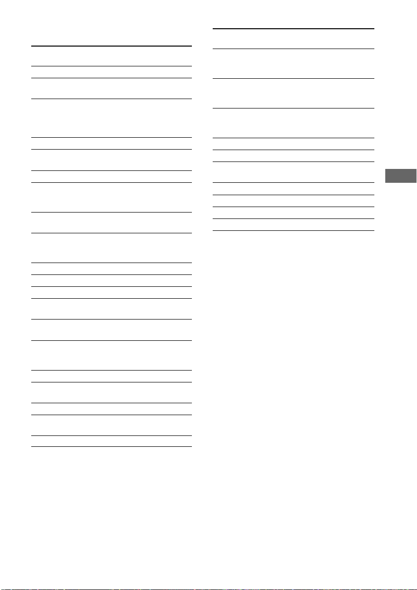
Description of program types
Program type Description
indication
NEWS News programs
AFFAIRS Topical programs that expand
on current news
INFO Programs offering information on
a wide spectrum of subjects,
including consumer affairs and
medical advice
SPORT Sports programs
EDUCATE Educational programs, such as
“how-to” and advice programs
DRAMA Radio plays and serials
CULTURE Programs about national or
regional culture, such as language
and social concerns
SCIENCE Programs about the natural
sciences and technology
VARIED Other types of programs such as
celebrity interviews, panel games,
and comedy
POP M Popular music programs
ROCK M Rock music programs
EASY M Easy Listening
LIGHT M Instrumental, vocal, and choral
music
CLASSICS Performances of major orchestras,
chamber music, opera, etc.
OTHER M Music that does not fit into any
categories above, such as Rhythm
& Blues and Reggae
WEATHER Weather information
FINANCE Stock market reports and trading,
etc.
CHILDREN Programs for children
SOCIAL Programs about people and the
things that affect them
RELIGION Programs of religious content
Program type Description
indication
PHONE IN Programs where members of the
public express their views by
phone or in a public forum
TRAVEL Programs about travel. Not for
announcements that are located by
TP/TA
LEISURE Programs on recreational activities
such as gardening, fishing,
cooking, etc.
JAZZ Jazz programs
COUNTRY Country music programs
NATION M Programs featuring the popular
music of the country or region
OLDIES Programs featuring oldies music
FOLK M Folk music programs
DOCUMENT Investigative features
NONE Any programs not defined above
Receiving Broadcasts
33
GB
Page 34
Other Operations
Naming preset stations
and program sources
You can enter a name (index name) of up to 8
characters for preset stations and program
sources. These names (for example, “VHS”)
appear in the receiver’s display when a station
or program source is selected. Note that no
more than one name can be entered for each
preset station or program source.
This function is useful for distinguishing
components of the same kind. For example,
two VCRs can be specified as “VHS” and
“8MM”, respectively. It is also handy for
identifying components connected to jacks
meant for another type of component, for
example, a second CD player connected to the
MD/TAPE jacks.
1 To name a preset station
Press TUNER FM/AM, then tune in the
preset station you want to create an
index name for.
If you are not familiar with how to tune in
preset stations, see “Tuning to preset
stations” on page 31.
To name a program source
Select the program source (component)
to be named.
2 Press MAIN MENU repeatedly to select
“ NAME ”.
3 Create an index name by using MENU +
or MENU – and MENU or MENU :
Press MENU + or MENU – to select a
character, then press MENU to move the
cursor to the next position.
To insert a space
Press MENU + or MENU – until a blank
space appears in the display.
If you’ve made a mistake
Press MENU or MENU repeatedly
until the character to be changed flashes,
then press MENU + or MENU – to select
the character you want.
4 Press ENTER.
5 Repeat steps 2 to 4 to assign index
name for another station or program
source.
Note
(Models of area code CEL, CEK only)
You cannot change the name of an RDS station.
Recording
Before you begin, make sure you’ve connected
all components properly.
Recording on an audio tape
or MiniDisc
You can record on a cassette tape or MiniDisc
using the receiver. See the operating
instructions of your cassette deck or MD deck
if you need help.
1 Select the component to be recorded.
2 Prepare the component for playing.
For example, insert a CD into the CD
player.
3 Insert a blank tape or MD into the
recording deck and adjust the
recording level, if necessary.
4 Start recording on the recording deck,
then start playback on the playback
component.
Notes
• Sound adjustments do not affect the signal output
from the MD/TAPE OUT jacks.
• (STR-DE595 only) When MULTI CH IN is
selected, the analog audio signals of the current
input source is output from the REC OUT jack.
• Some sources contain copy guards to prevent
recording. In this case, you may not be able to
record from the sources.
34
GB
Page 35
Recording on a video tape
You can record from a VCR, a TV or a DVD
player using the receiver. You can also add
audio from a variety of audio sources when
editing a video tape. See the operating
instructions of your VCR or DVD player if you
need help.
1 Select the program source to be
recorded.
2 Prepare the component for playing.
For example, insert the DVD you want to
record into the DVD player.
3 Insert a blank video tape into the VCR
(VIDEO 1) for recording.
4 Start recording on the recording VCR,
then start playing the video tape or
DVD you want to record.
Tip
You can record the sound from any audio source onto
a video tape while copying from a video tape or
DVD. Locate the point where you want to start
recording from another audio source, select the
program source, then start playback. The audio from
that source will be recorded onto the audio track of
the video tape instead of the audio from the original
medium. To resume audio recording from the original
medium, select the video source again.
Notes
• Make sure to make both digital and analog
connections to the VIDEO 2 and DVD inputs.
Analog recording is not possible if you make only
digital connections.
• (STR-DE595 only) When MULTI CH IN is
selected, the analog audio signals of the current
input source is output from the REC OUT jacks.
Using the Sleep Timer
You can set the receiver to turn off
automatically at a specified time.
Press SLEEP on the remote while the
power is on.
Each time you press the button, the display
changes cyclically as follows:
2-00-00 t 1-30-00 t 1-00-00 t 0-30-00 t
OFF
Tip
To check the remaining time before the receiver turns
off, press SLEEP. The remaining time appears in the
display.
Adjustments using the
SET UP menu
The SET UP menu allows you to make the
following adjustments.
1 Press MAIN MENU repeatedly to select
“ SET UP ”.
2 Press MENU or MENU to select
the parameter you want to adjust.
3 Press MENU + or MENU – to select the
setting you want.
The setting is entered automatically.
Initial settings
Parameter Initial setting
DEC. XXXX PCM (for DVD,
CD/SACD
(STR-DE595
only)), AUTO
(for VIDEO 2)
Other Operations
continued
35
GB
Page 36

Adjustments using the SET UP menu
(continued)
x Decode priority (DEC. XXXX)
Sets the appropriate decoding for incoming
digital signals.
• PCM priority mode (DEC. PCM)
Use to enjoy playback from audio CD
(PCM) and DVD. When used with media
other than CD or DVD, you may experience
noise. If this happens, switch to AUTO
mode.
• AUTO mode (DEC. AUTO)
Use to enjoy playback from audio CD
(PCM), DVD, DTS-CD and DTS-LD
sources. However, with audio CDs, you may
not be able to listen the very first moments
of each track.
Normally, use as-is with the initial settings
above.
Changing the command
mode of the receiver
This function is useful when you use 2 Sony
receivers in the same room.
1 Turn off the receiver.
2 Hold down ENTER and press 1/u to
turn on the receiver.
“C.MODE.AVX” appears in the display.
Each time you repeat the procedure above,
the display changes as follows:
C.MODE.AV1 y C.MODE.AV2
Tip
The initial setting is “C.MODE.AV2”.
Notes
• The command mode of the supplied remote is
“AV2” and you cannot change this setting.
• If the command mode of the receiver and the
remote is different, you cannot use the remote to
operate the receiver.
36
GB
Page 37
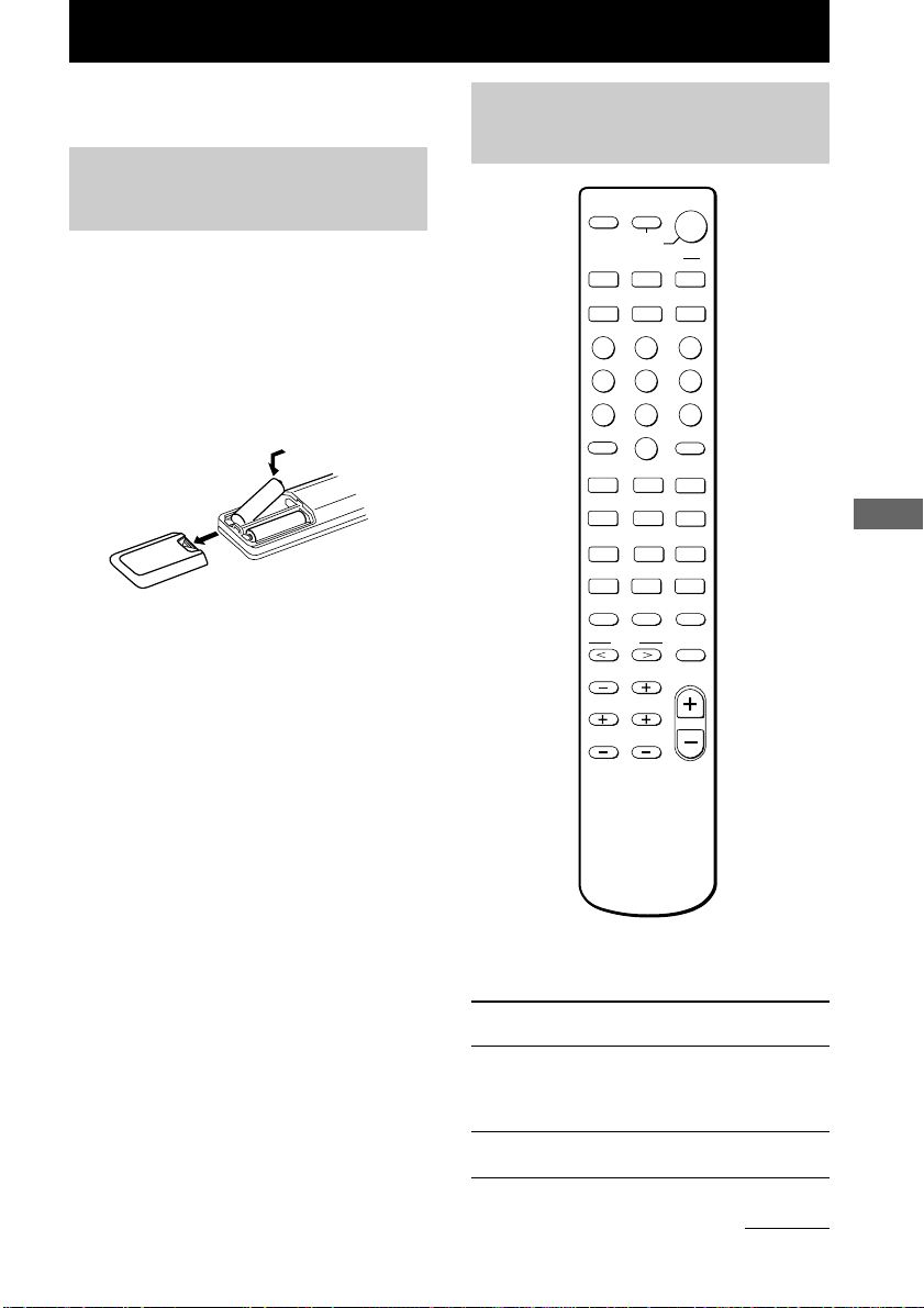
Operations Using the Remote RM-U306A
You can use the remote RM-U306A to operate
the components in your system.
Before you use your
remote
Inserting batteries into the
remote
Insert R6 (size-AA) batteries with the + and –
properly oriented in the battery compartment.
When using the remote, point it at the remote
sensor g on the receiver.
]
}
}
]
Tip
Under normal conditions, the batteries should last for
about 6 months. When the remote no longer operates
the receiver, replace all batteries with new ones.
Notes
• Do not leave the remote in an extremely hot or
humid place.
• Do not use a new battery with an old one.
• Do not expose the remote sensor to direct sunlight
or lighting apparatuses. Doing so may cause a
malfunction.
• If you don’t use the remote for an extended period
of time, remove the batteries to avoid possible
damage from battery leakage and corrosion.
Remote button
description
AV
SLEEP
?/1
SYSTEM
STANDBY
VIDEO 1
VIDEO 2
MD/TAPE CD TUNER
TOP MENU DVD MENU
123
G
456
7809
SHIFT
>10
-
+
–
CH/PRESET
.
>
m
M
X
N
2CH A.F.D.
TEST TONE MAIN MENU MULTI CH
MENU
TV VOL TV CH
F
ENTER
f
?/1
DVD
g
O
D.TUNING
ENTER
RETURN
TV/VIDEO
ANT
TV/VTR
D.SKIP
x
MOVIE/
MUSIC
MUTING
MASTER
VOL
Operations Using the Remote RM-U306A
The tables below show the settings of each
button.
Remote Operations Function
Button
SLEEP Receiver Activates the sleep
function and the duration
which the receiver turns
off automatically.
?/1 Receiver Turns the receiver on or
off.
continued
37
GB
Page 38

Remote button description
(continued)
Remote Operations Function
Button
VIDEO 1 Receiver To watch VCR.
VIDEO 2 Receiver To watch VCR.
DVD Receiver To watch DVD.
MD/TAPE Receiver To listen to Minidisc or
CD Receiver To listen to compact disc.
TUNER Receiver To listen to radio
SHIFT Receiver Press repeatedly to select
D.TUNING
2CH Receiver Selects 2CH mode.
A.F.D. Receiver Selects A.F.D. AUTO,
MOVIE/ Receiver Selects C.ST.EX A,
MUSIC C.ST.EX B, C.ST.EX C,
TEST Receiver Press to output test tone.
TONE
MAIN Receiver Press this button
MENU repeatedly to select one
MULTI CH
MENU </> Receiver Selects a menu item.
MENU +/– Receiver Makes adjustment or
MUTING Receiver Mutes the sound from the
Receiver Tuner station direct key-
Receiver Selects MULTI CH IN
(VTR mode 3)
(VTR mode 1)
audio tape.
programs.
a memory page for
presetting radio stations
or tuning to preset
stations.
in-mode.
DOLBY PL, PLII MOV
and PLII MUS.
HALL, JAZZ and
CONCERT.
of the four cursor modes:
SET UP, LEVEL, TONE
and NAME.
source.
change the setting.
receiver.
Remote Operations Function
Button
MASTER Receiver Adjusts the master
VOL +/– volume of the receiver.
AV ?/1 TV/VCR/ Turns the audio and
CD player/ video components on or
VCD player/ off.
LD player/
DVD player/
MD deck/
DAT deck
SYSTEM Receiver/TV/ Turns off the receiver and
STANDBY VCR/Satellite other Sony audio/video
(Press AV tuner/ components.
?/1 and CD player/
?/1 at VCD player/
the same LD player/
time) DVD player/
MD deck/
DAT deck
0-9 Receiver Use with “SHIFT” button
to preset radio station or
tuning to preset stations
and with “D.TUNING”
for direct tuning.
CD player/ Selects track numbers.
VCD player/ 0 selects track 10.
LD player/
MD deck/
DAT deck
TV/VCR/ Selects channel numbers.
Satellite tuner
>10 CD player/ Selects track numbers
VCD player/ over 10.
LD player/
MD deck/
Tape deck
38
GB
Page 39
Remote Operations Function
Button
ENTER TV/VCR/ After selecting a channel,
Satellite tuner/ disc or track using the
LD player/ numeric buttons, press to
MD deck/ enter the value.
DAT deck/
Tape deck
RETURN VCD player Go back to previous
menu.
CH/ Receiver Scans and selects preset
PRESET stations.
+/-
TV/VCR/ Selects preset channel.
Satellite tuner
./> VCR/ Skips tracks.
CD player/
VCD player/
LD player/
DVD player/
MD deck/
DAT deck/
Tape deck
m/M CD player/ Searches tracks (forward
VCD player/ or backward).
DVD player
VCR/ Fastforwards or rewinds.
LD player/
MD deck/
DAT deck/
Tape deck
N VCR/ Starts play.
CD player/
VCD player/
LD player/
DVD player/
MD deck/
DAT deck/
Tape deck
Remote Operations Function
Button
X VCR/ Pauses play or record.
x VCR/ Stops play.
ANT VCR Selects output signal
TV/VTR from the aerial terminal:
D.SKIP
TOP DVD player Displays DVD title.
MENU
DVD DVD player Displays DVD menu.
MENU
ENTER DVD player Enters the selection.
O DVD player Returns to the previous
V/v/B/b
CD player/ (Also start recording
VCD player/ with components in
LD player/ record standby.)
DVD player/
MD deck/
DAT deck/
Tape deck
CD player/
VCD player/
LD player/
DVD player/
MD player/
DAT deck/
Tape deck
TV signal or VCR
program.
CD player/ Skips discs (multi-disc
VCD player/ changer only).
DVD player/
MD deck
menu or exits the menu.
DVD player Selects a menu item.
continued
Operations Using the Remote RM-U306A
39
GB
Page 40

Remote button description
(continued)
Remote Operations Function
Button
÷ TV Selects the channel entry
TV/VIDEO
TV VOL
+/– TV
TV CH
+/– channels
Notes
• When you press the input selector buttons (VIDEO
1, VIDEO 2, DVD), the input mode of the TV
might not switch to the corresponding input mode
that you want. In this case, press the TV/VIDEO
button to switch the input mode of the TV.
• Some functions explained in this section may not
work depending on the model of the receiver.
• The above explanation is intended to serve as an
example only.
Therefore, depending on the component the above
operation may not be possible or may operate
differently than described.
• (STR-DE495 only) The MULTI CH function is not
available for set operation.
TV Selects input signal: TV
TV Adjusts the volume of the
TV Selects preset TV
mode, either one or two
digit
input or video input.
Changing the factory
setting of an input selector
button
1 Hold down the input selector button
whose input source you want to change
(for example, MD/TAPE).
2 Press the corresponding button of the
component you want to assign to the
input selector button (for example, 4 –
Tape deck).
The following buttons are assigned to select
the input source:
To operate Press
CD player 1
DAT deck 2
MD deck 3
Tape deck A 4
Tape deck B 5
LD player 6
VCR (command mode VTR 1*) 7
VCR (command mode VTR 2*) 8
VCR (command mode VTR 3*) 9
TV 0
DSS (Digital Satellite Receiver) >10
DVD ENTER
VCD player .
* Sony VCRs are operated with a VTR 1, 2 or 3
setting. These correspond to Beta, 8mm and
VHS respectively.
Now you can use the MD/TAPE button to
control the tape deck.
To reset a button to its factory
setting
Repeat the above procedure.
If the factory settings of the input selector
buttons do not match your system components,
you can change them. For example, if you have
a tape deck and you do not have an MD deck,
you can assign the MD/TAPE button to your
tape deck.
Note that the settings of the TUNER button
cannot be changed.
GB
40
To reset all the input selector
buttons to their factory setting
Press ?/1, AV ?/1 and MASTER VOL – at
the same time.
Page 41
Additional Information
Precautions
On safety
Should any solid object or liquid fall into the cabinet,
unplug the receiver and have it checked by qualified
personnel before operating it any further.
On power sources
• Before operating the unit, check that the operating
voltage is identical with your local power supply.
The operating voltage is indicated on the nameplate
at the rear of the receiver.
• The unit is not disconnected from the AC power
source (mains) as long as it is connected to the wall
outlet, even if the receiver itself has been turned off.
• If you are not going to use the receiver for a long
time, be sure to disconnect the receiver from the
wall outlet. To disconnect the AC power cord,
grasp the plug itself; never pull the cord.
• (Models of area code U, CA only)
One blade of the plug is wider than the other for the
purpose of safety and will fit into the wall outlet
only one way. If you are unable to insert the plug
fully into the outlet, contact your dealer.
• AC power cord must be changed only at the
qualified service shop.
On heat buildup
Although the unit heats up during operation, this is
not a malfunction. If you continuously use this unit at
a large volume, the cabinet temperature of the top,
side and bottom rises considerably. To avoid burning
yourself, do not touch the cabinet.
On placement
• Place the receiver in a location with adequate
ventilation to prevent heat buildup and prolong the
life of the receiver.
• Do not place the receiver near heat sources, or in a
place subject to direct sunlight, excessive dust or
mechanical shock.
• Do not place anything on top of the cabinet that
might block the ventilation holes and cause
malfunctions.
• Use caution when placing the unit on surfaces that
have been specially treated (with wax, oil, polish,
etc.) as staining or discoloration of the surface may
result.
On operation
Before connecting other components, be sure to turn
off and unplug the receiver.
On cleaning
Clean the cabinet, panel and controls with a soft cloth
slightly moistened with a mild detergent solution. Do
not use any type of abrasive pad, scouring powder or
solvent such as alcohol or benzine.
If you have any question or problem concerning your
receiver, please consult your nearest Sony dealer.
Troubleshooting
If you experience any of the following
difficulties while using the receiver, use this
troubleshooting guide to help you remedy the
problem. Also, see “Checking the connections”
on page 20 to verify that the connections are
correct. Should any problem persist, consult
your nearest Sony dealer.
There is no sound or only a very low-level sound
no matter which component is selected.
• Check that the speakers and components are
connected securely and correctly.
• Check that both the receiver and all components
are turned on.
• Check that the MASTER VOLUME control is
not set at “VOL MIN”.
• Press MUTING on the remote to cancel the
muting function.
• (STR-DE595 only) Check that the SPEAKERS
(OFF/A/B/A+B) button is not set to off and is set
accordingly to your SPEAKERS FRONT system
(page 22).
• Check that the headphones are not connected.
• The protective device on the receiver has been
activated because of a short circuit (“PROTECT”
flashes). Turn off the receiver, eliminate the
short-circuit problem and turn on the power
again.
continued
Additional Information
41
GB
Page 42

Troubleshooting (continued)
There is no sound from a specific component.
• Check that the component is connected correctly
to the audio input jacks for that component.
• Check that the cord(s) used for the connection is
(are) fully inserted into the jacks on both the
receiver and the component.
• Check that you have selected the correct
component on the receiver.
There is no sound from one of the front
speakers.
Connect a pair of headphones to the PHONES jack
to verify that sound is output from the headphones
(page 22).
If only one channel is output from the headphones,
the component may not be connected to the
receiver correctly. Check that all the cords are fully
inserted into the jacks on both the receiver and the
component.
If both channels are output from the headphones,
the front speaker may not be connected to the
receiver correctly. Check the connection of the
front speaker which is not outputting any sound.
The left and right sounds are unbalanced or
reversed.
• Check that the speakers and components are
connected correctly and securely.
• Adjust balance parameters in the LEVEL menu.
There is severe hum or noise.
• Check that the speakers and components are
connected securely.
• Check that the connecting cords are away from a
transformer or motor, and at least 3 meters away
from a TV set or fluorescent light.
• Move your TV away from the audio components.
• The plugs and jacks are dirty. Wipe them with a
cloth slightly moistened with alcohol.
There is no sound or only a very low level sound
is heard from the center or/and surround
speaker.
• Make sure the sound field function is on (press
MOVIE or MUSIC).
• Select a sound field containing the word
“C.ST.EX” (pages 24).
• Adjust the speaker level (page 20).
• Make sure the center or/and surround speaker
size parameter is set to either “SMALL” or
“LARGE” (page 17).
There is no sound from the active sub woofer.
• Check that the sub woofer is connected correctly
and securely.
• Make sure the sub woofer selection parameter is
set to “YES” (page 17).
• There is no sound output from the SUB
WOOFER terminal depending on the sound field
(page 48).
The surround effect cannot be obtained.
Make sure the sound field function is on (press
MOVIE or MUSIC).
Dolby Digital or DTS multi channel sound is not
reproduced.
• Check that the playing DVD, etc. is recorded in
Dolby Digital or DTS format.
• When connecting the DVD player, etc. to the
digital input jacks of this receiver, check the
audio setting (settings for the audio output) of the
connected component.
Recording cannot be done.
• Check that the components are connected
correctly.
• Select the source component with input selector
buttons.
• Make sure that INPUT MODE is set to
“ANALOG” (page 21) before recording from a
digital component connected to the analog
MD/TAPE terminals.
42
GB
Page 43
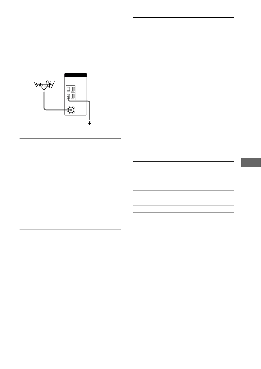
The FM reception is poor.
Use a 75-ohm coaxial cable (not supplied) to
connect the receiver to an outdoor FM antenna as
shown below. If you connect the receiver to an
outdoor antenna, ground it against lightning. To
prevent a gas explosion, do not connect the ground
wire to a gas pipe.
Receiver
Outdoor FM antenna
Radio stations cannot be tuned in.
ANTENNA
AM
COAXIAL
y
FM
75Ω
To ground
Ground wire
(not supplied)
• Check that the antennas are connected securely.
Adjust the antennas and connect an external
antenna if necessary.
• The signal strength of the stations is too weak
(when tuning in with automatic tuning). Use
direct tuning.
• Make sure you set the tuning interval correctly
(when tuning in AM stations with direct tuning).
• No stations have been preset or the preset
stations have been cleared (when tuning by
scanning preset stations). Preset the stations
(page 31).
• Press DISPLAY so that the frequency appears in
the display.
RDS does not work.*
• Make sure that you’re tuned to an FM RDS
station.
• Select a stronger FM station.
The RDS information that you want does not
appear.*
Contact the radio station and find out whether they
actually provide the service in question. If so, the
service may be temporarily out of order.
There is no picture or an unclear picture appears
on the TV screen or monitor.
• Select the appropriate input selector on the
receiver.
• Set your TV to the appropriate input mode.
• Move your TV away from the audio components.
The remote does not function.
• (STR-DE495 only) The MULTI CH button on
the remote is not available.
• Point the remote at the remote sensor g on the
receiver.
• Make sure you select AV2 as the command
mode of the receiver (page 36).
• Remove any obstacles in the path between the
remote and the receiver.
• Replace both batteries in the remote with new
ones, if they are weak.
• Make sure you select the correct input selector
on the remote.
• If the remote is set to operate the TV only, use
the remote to select a source or component other
than TV before operating the receiver or other
component.
* Models of area code CEL, CEK only.
Clearing the receiver’s memory
To clear See
All memorized settings page 15
Customized sound fields page 28
Additional Information
43
GB
Page 44

Specifications
AUDIO POWER SPECIFICATIONS
POWER OUTPUT AND TOTAL
HARMONIC DISTORTION:
With 8 ohm loads, both channels driven, from 40 –
20,000 Hz; rated 90 watts (STR-DE595 only) per
channel minimum RMS power, with no more than
0.09 % total harmonic distortion from 250 milliwatts
to rated output (models of area code U only).
Amplifier section
POWER OUTPUT
Models of area code U, CA
Rated Power Output at Stereo Mode
(8 ohms 40 Hz – 20 kHz, THD 0.09 %)
STR-DE595: 90 W + 90 W
STR-DE495: 70 W + 70 W
Reference Power Output
(8 ohms 40 Hz – 20 kHz, THD 0.09 %)
STR-DE595: FRONT1):90 W/ch
STR-DE495: FRONT1): 70 W/ch
(8 ohms 1 kHz, THD 0.7 %)
STR-DE595: FRONT1):100 W/ch
STR-DE495: FRONT1): 80 W/ch
Models of area code CEL, CEK
Rated Power Output at Stereo Mode
(8 ohms 1 kHz, THD 0.7 %)
STR-DE595: 100 W + 100 W
STR-DE495: 80 W + 80 W
Reference Power Output
(8 ohms 1 kHz, THD 0.7 %)
STR-DE595: FRONT1):100 W/ch
STR-DE495: FRONT1): 80 W/ch
Models of area code SP
Rated Power Output at Stereo Mode
(8 ohms 1 kHz, THD 0.7 %)
STR-DE595: 90 W + 90 W
STR-DE495: 70 W + 70 W
CENTER1): 90 W
SURR1): 90 W/ch
CENTER1): 70 W
SURR1): 70 W/ch
CENTER1): 100 W
SURR1): 100 W/ch
CENTER1): 80 W
SURR1): 80 W/ch
2)
2)
2)
CENTER1): 100 W
SURR1): 100 W/ch
CENTER1): 80 W
SURR1): 80 W/ch
2)
2)
Reference Power Output
2)
(8 ohms 1 kHz, THD 10 %)
STR-DE595: FRONT1): 110 W/ch
CENTER1): 110 W
SURR1): 110 W/ch
STR-DE495: FRONT1): 90 W/ch
CENTER1): 90 W
SURR1): 90 W/ch
Models of area code CN, KR
Rated Power Output at Stereo Mode
(8 ohms 1 kHz, THD 0.7 %)
STR-DE595: 100 W + 100 W
90 W + 90 W
STR-DE495: 80 W + 80 W
Reference Power Output
(8 ohms 1 kHz, THD 10 %)
70 W + 70 W
2)
2)
3)
2)
3)
STR-DE595: FRONT1): 120 W/ch
CENTER1): 120 W
SURR1): 120 W/ch
STR-DE495: FRONT1): 100 W/ch
CENTER1): 100 W
SURR1): 100 W/ch
Models of other area code
Rated Power Output at Stereo Mode
(8 ohms 1 kHz, THD 0.7 %)
STR-DE595: 100 W + 100 W
STR-DE495: 80 W + 80 W
Reference Power Output
(8 ohms 1 kHz, THD 10 %)
2)
2)
2)
STR-DE595: FRONT1): 120 W/ch
CENTER1): 120 W
SURR1): 120 W/ch
STR-DE495: FRONT1): 100 W/ch
CENTER1): 100 W
SURR1): 100 W/ch
1) Depending on the sound field settings and the
source, there may be no sound output.
2) Measured under the following conditions:
Area code Power requirements
E2/E3 240 V AC, 50 Hz
SP, CEL, CEK, AR, 230 V AC, 50 Hz
CN, KR
TW 110 V AC, 60 Hz
3) Measured under the following conditions:
Area code Power requirements
CN, KR 220 V AC, 50 Hz
44
GB
Page 45
Frequency response
MULTI CH IN
(STR-DE595 only), CD
(STR-DE495 only),
10 Hz – 50 kHz
+0.5/–2 dB (with sound
field and tone bypassed)
MD/TAPE, DVD,
VIDEO 1, 2
CD/SACD (STR-DE595
only)
10 Hz – 70 kHz
+0.5/–2 dB (with sound
field and tone bypassed)
Inputs (Analog)
MULTI CH IN
(STR-DE595 only), CD/
SACD (STR-DE595
only), CD (STR-DE495
Sensitivity: 500 mV
Impedance: 50 kilohms
S/N4): 96 dB
(A, 500 mV5))
only), MD/TAPE, DVD,
VIDEO 1, 2
4) INPUT SHORT (with sound field and tone
bypassed).
5) Weighted network, input level.
Inputs (Digital)
DVD (Coaxial)
Sensitivity: –
Impedance: 75 ohms
S/N: 100 dB
(A, 20 kHz LPF)
CD/SACD (Optical)
(STR-DE595 only),
VIDEO 2 (Optical)
Sensitivity: –
Impedance: –
S/N: 100 dB
(A, 20 kHz LPF)
Outputs
MD/TAPE (OUT),
VIDEO 1
Voltage: 500 mV
Impedance: 10 kilohms
(AUDIO OUT)
SUB WOOFER
Voltage: 2 V
Impedance: 1 kilohms
Tone
Gain levels: ±6 dB, 1 dB step
FM tuner section
Tuning range 87.5 - 108.0 MHz
Antenna terminals 75 ohms, unbalanced
Intermediate Frequency
10.7 MHz
Sensitivity
Mono: 18.3 dBf, 2.2 µV/75 ohms
Stereo:
38.3 dBf, 22.5 µV/75 ohms
Usable sensitivity 11.2 dBf, 1 µV/75 ohms
S/N
Mono: 76 dB
Stereo: 70 dB
Harmonic distortion at 1 kHz
Mono: 0.3%
Stereo: 0.5%
Separation 45 dB at 1 kHz
Frequency response 30 Hz – 15 kHz,
+0.5/–2 dB
Selectivity 60 dB at 400 kHz
AM tuner section
Tuning range
Models of area code U, CA
With 10-kHz tuning scale: 530 – 1710 kHz
With 9-kHz tuning scale: 531 – 1710 kHz
Models of area code E2/E3
With 10-kHz tuning scale: 530 – 1610 kHz
With 9-kHz tuning scale: 531 – 1602 kHz
Models of area code CEL, CEK, SP, CN, TW,
6)
6)
6)
6)
KR, AU
With 9-kHz tuning scale: 531 – 1602 kHz
Models of area code AR, MX
With 10-kHz tuning scale: 530 – 1610 kHz
Antenna Loop antenna
Intermediate Frequency
Usable sensitivity 50 dB/m (at 1,000 kHz or
450 kHz
999 kHz)
S/N 54 dB (at 50 mV/m)
Harmonic distortion 0.5 % (50 mV/m, 400 Hz)
Selectivity
At 9 kHz: 35 dB
At 10 kHz: 40 dB
6) You can change the AM tuning scale to 9 kHz or
10 kHz. After tuning in any AM station, turn off
the receiver. Hold down PRESET TUNING + and
press ?/1. All preset stations will be erased when
you change the tuning scale. To reset the scale to
10 kHz (or 9 kHz), repeat the procedure.
continued
Additional Information
45
GB
Page 46
Specifications (continued)
Video section
Inputs
Video: 1 Vp-p, 75 ohms
Component Video (STR-DE595 only, except for
models of area code CEL, CEK):
Y: 1 Vp-p, 75 ohms
PB/B-Y: 0.7 Vp-p, 75 ohms
PR/R-Y: 0.7 Vp-p, 75 ohms
Outputs
Video: 1 Vp-p, 75 ohms
Component Video (STR-DE595 only, except for
models of area code CEL, CEK):
Y: 1 Vp-p, 75 ohms
PB/B-Y: 0.7 Vp-p, 75 ohms
PR/R-Y: 0.7 Vp-p, 75 ohms
General
Power requirements
Area code Power requirements
U, CA, MX 120 V AC, 60 Hz
CEL, CEK 230 V AC, 50/60 Hz
SP, AR, CN, KR 220 – 230 V AC, 50/60 Hz
E2/E3 120/220/240 V AC, 50/60 Hz
TW 110 V AC, 50/60 Hz
AU 240 V AC, 50Hz
Power consumption
Area code Power consumption
U, MX STR-DE595: 210 W
CA STR-DE595: 310 VA
CEL, CEK, TW, STR-DE595: 210 W
KR STR-DE495: 180 W
SP STR-DE595: 180 W
CN STR-DE595: 205 W
AU, E2/E3, AR STR-DE595: 210W
Power consumption (during standby mode)
0.3 W
Dimensions 430 × 145 × 298 mm
Mass (Approx.)
STR-DE595: 7.5 kg (16 lb 9 oz)
STR-DE495: 7.2 kg (15 lb 14 oz)
Supplied accessories
FM wire antenna (1)
AM loop antenna (1)
Remote commander RM-U306A (1)
R6 (size-AA) batteries (2)
For details on the area code of the component you
are using, see page 4.
STR-DE495: 250 VA
STR-DE495: 180 W
(16 7/8 × 5 6/8 × 11 6/8 in.)
including projecting parts
and controls
46
Design and specifications are subject to change
without notice.
GB
Page 47
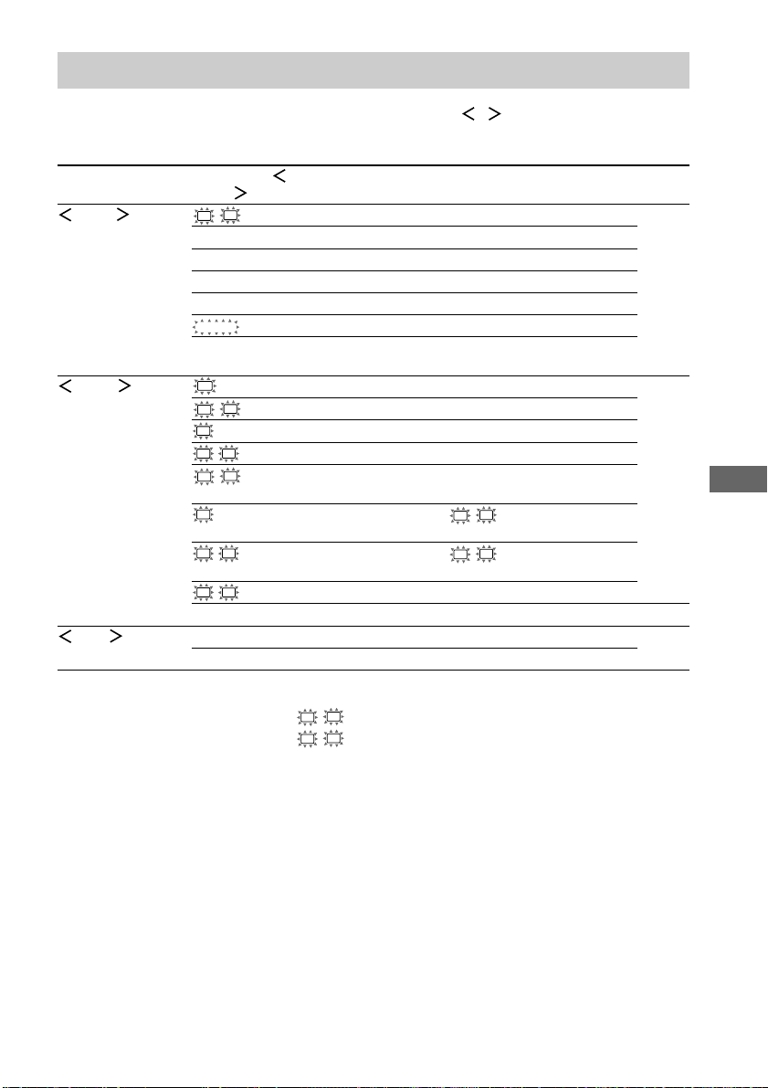
Tables of settings using the MAIN MENU button
You can make various settings using the MAIN MENU, MENU / and MENU +/– buttons. The
tables below show each of the settings that these buttons can make.
Press MAIN MENU Press MENU or Press MENU + or Page
repeatedly to select MENU
LEVEL
SET UP
TONE BASS XX dB –6 dB to +6 dB (1 dB steps) 28
to select MENU – to select
L
R BAL. L/R XX L +8 to R +8 (1 steps) 27
CTR XXX dB –10 dB to +10 dB (1 dB steps)
SUR.L. XXX dB –10 dB to +10 dB (1 dB steps)
SUR.R. XXX dB –10 dB to +10 dB (1 dB steps)
S.W. XXX dB –10 dB to +10 dB (1 dB steps)
COMP. XXX OFF, STD, MAX
D. RANGE
EFCT. XXX depends on the sound field
(MIN, STD, MAX)
SW
(SUB WOOFER) S.W. XXX YES, NO 16
L
R (FRONT) XXXXX LARGE, SMALL
C
(CENTER) XXXXX LARGE, SMALL, NO
SL
SR (SURROUND) XXXXX LARGE, SMALL, NO
L
R DIST. X.X m (XX ft.) between 1.0 meters and 7.0 meters
(0.1 meters steps)
C
DIST. X.X m (XX ft.) between L R DIST. and 1.5 meters
(0.1 meters steps)
SL
SR DIST. X.X m (XX ft.) between L R DIST. and 4.5 meters
(0.1 meters steps)
SL
SR PL. XXXX LOW, HIGH
1)
2)
3)
DEC. XXXX AUTO, PCM 35
TREB. XX dB –6 dB to +6 dB (1 dB steps)
Additional Information
1)
For models of area code U, CA: 3 feet to 23 feet (1 foot steps)
2)
For models of area code U, CA: between L R DIST. and 5 feet (1 foot steps)
3)
For models of area code U, CA: between L R DIST. and 15 feet (1 foot steps)
47
GB
Page 48

Adjustable parameters for each sound field
The adjusted BASS and TREB. parameters are applied to all sound fields.
< TONE >
BASS TREB.
2CH ST. zz
A.F.D. AUTO zz
DOLBY PL zz
PLII MOV zz
PLII MUS zz
C.ST.EX A zz
C.ST.EX B zz
C.ST.EX C zz
HALL zz
JAZZ zz
CONCERT zz
MULTI CH IN
PCM 96K
The adjusted LEVEL parameters are applied to all the sound fields except for EFCT. parameter. For
EFCT. parameter, the settings are stored individually for each sound field.
2CH ST. zz
A.F.D. AUTO zzzzzz
DOLBY PL zzzzzz
PLII MOV zzzzzz
PLII MUS zzzzzz
C.ST.EX A zzzzzzz
C.ST.EX B zzzzzzz
C.ST.EX C zzzzzzz
HALL zzzz z3)zz
JAZZ zzzz z3)zz
CONCERT zzzz z3)zz
MULTI CH IN
PCM 96K z
1)
STR-DE595 only.
2)
These parameters may not operate depending on the source or adjustments. For details, see each item in
“Adjusting the level parameters” (page 27).
3)
When these sound fields are selected, there is no sound output from the sub woofer if the front speaker size is
set to “LARGE”. However, sound will be output from the sub woofer if the digital input signal contains LFE
signals.
1)
< LEVEL >
FRONT CENTER SUR.L. SUR.R. S.W. D.RANGE EFCT.
BAL LEVEL LEVEL LEVEL LEVEL COMP
1)
zzzzz
2)
LEVEL
48
GB
Page 49
警告
為防火災或觸電危險,請勿讓本裝置淋雨或受
潮。
為防火災,請勿用報紙,桌布,窗簾等遮蓋裝置
的通風孔。也不可在裝置上點放蠟燭。
為防火災或觸電危險,不可在裝置上放置花瓶等
盛滿液體的物體。
不可將電池與普通家庭垃圾一起
丟棄,必須將它當作化學品垃圾
正確地處理。
請勿安裝本機于諸如書櫥或壁櫥等狹隘不通風的
地方。
歐洲的顧客除外
ENERGY STAR
標。
作為 ENERGY STAR®的合作伙伴
之一,Sony Corporation 已確定此產
品符合 ENERGY STAR®能量效率的標
準。
上海索廣電子有限公司
上海市 閔行區 劍川路930號
本接收機含有杜比*數字 (Dolby* Digital),專
業邏輯環繞聲 (Pro Logic Surround) 和 DTS**
數字環繞聲系統 (DTS** Digital Surround
System)。
* 由杜比研究所 (Dolby Laboratories) 授權製
造。
“Dolby”,“Pro Logic”和雙 D 標誌是杜比
研究所的注冊商標。
** “DTS”和“DTS Digital Surround”是數字電
影院系統股份有限公司 (Digital Theater
Systems, Inc.) 的注冊商標。
®
是一美國的注冊商
CS
2
Page 50
目錄
按鈕位置和參照頁數一覽表
主機 ........................... 5
連接單片機
所需導線 ....................... 6
天線連接 ....................... 7
聲頻單片機的連接 ............... 8
視頻單片機的連接 ............... 9
數字單片機的連接 .............. 10
1)
多重聲道輸入的連接
........... 11
其他連接 ...................... 12
連接和設置揚聲器系統
連接揚聲器系統 ................ 13
執行初始設置操作 .............. 15
多重聲道環繞聲的設置 .......... 15
檢查連接 ...................... 20
基本操作
選擇單片機 .................... 21
改變顯示 ...................... 22
享受環繞聲
僅使用前揚聲器
(2 聲道立體聲) ............. 23
享受高保真度音響 .............. 23
選擇聲場 ...................... 24
多重聲道環繞聲顯示說明 ........ 26
定製聲場 ...................... 27
接收廣播
自動存儲 FM 電台
(AUTOBETICAL)2)............ 29
直接調諧 ...................... 29
自動調諧 ...................... 30
預約調諧 ...................... 30
使用無線電廣播數據系統
(RDS)
2)
.................... 32
其他操作
為預約電台和節目信號源定名 .... 34
錄音∕影 ...................... 34
使用睡眠定時器 ................ 35
用 SET UP 選單進行調整 ........ 35
改變接收機的指令模式 .......... 36
用 RM-U306A 遙控器操作
在使用您的遙控器之前 .......... 37
遙控器按鈕說明 ................ 37
改變輸入選擇器按鈕的出廠
預設 ....................... 40
附加信息
使用前注意事項 ................ 41
故障探尋 ...................... 41
規格 .......................... 44
使用 MAIN MENU 按鈕的設定
一覽表 ..................... 47
各聲場的可調整參數 .......... 封底
CS
1)
STR-DE595 型號為限。
2)
地區碼 CEL,CEK 的型號為限。
CS
3
Page 51
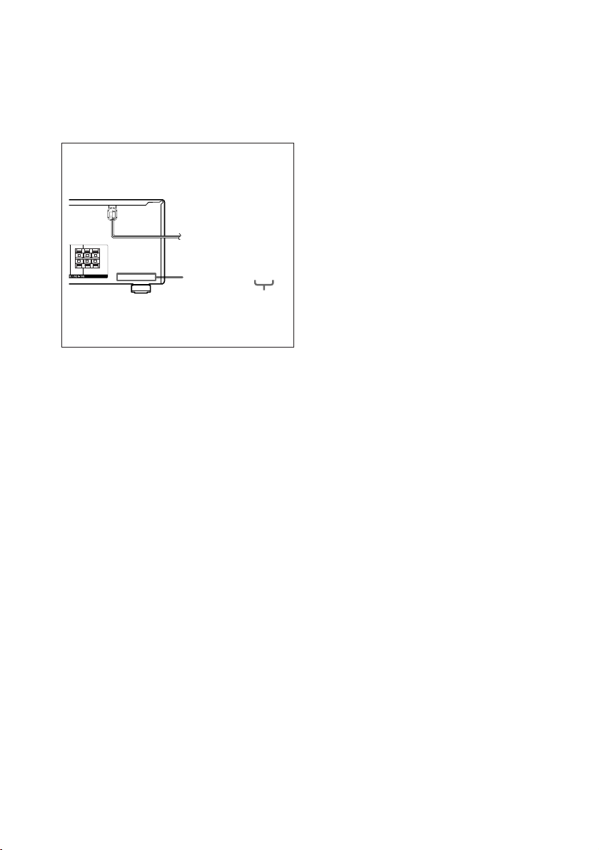
關于本說明書
本說明書供 STR-DE595 和 STR-DE495 型號所
用。請查看前面板右下角的型號編碼。本說明書以
STR-DE595 作為圖示說明,除非另有說明。任何操
作上的異同都在說明書中清楚地指明,例如,
“STR-DE595 型號為限”。
關于地區碼
您所購買的接收機的地區碼標示在后面板下部
(參看下圖)。
RRL
+—+
—
L
CENTER SURROUND
依據地區碼,任何操作上的不同都已在文中說
明。例如,“地區碼 AA 的型號為限”。
要領
本說明書說明接收機的控制器。您也可用附帶遙
控器上的控制按鈕,如果它與接收機上的控制按
鈕具有相同或類似名稱。有關遙控器的使用詳
情,請參照第 37-40 頁。
4-XXX-XXX-XX AA
地區碼
附帶遙控器需知
對于 RM-U306A
(STR-DE495 型號為限) 遙控器上的
MULTI CH 按鈕不起作用。
CS
4
Page 52
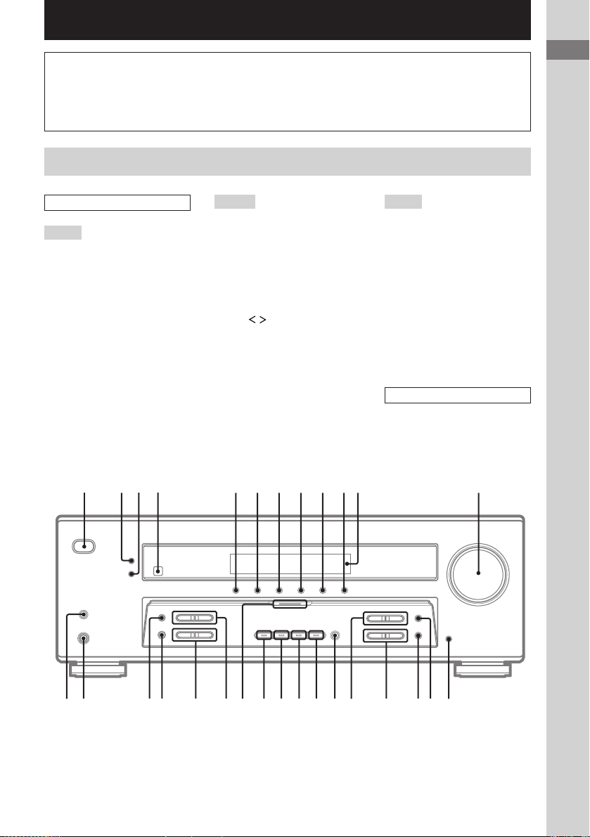
按鈕位置和參照頁數一覽表
1234 56789q;q
q
如何使用此頁
利用此頁查找在文中所提及的按鈕的位置。
主機
按字母順序排列
A – L
A.F.D. (按鈕/指示燈) wa
(23-25)
CD (STR-DE495 型號為限) 9
(21)
CD/SACD (STR-DE595 型號為
限) 9 (21)
DIMMER 3 (22)
DISPLAY 2 (22,32,43)
DVD 7 (21)
ENTER qg (34,36)
FM MODE wh (30)
INPUT MODE qd (21)
IR (接收器) 4 (37, 43)
M – O
MAIN MENU qf (16,27,
28,34,35,47)
MASTER VOLUME qs (20,
21,41)
MD/TAPE 8 (21)
MEMORY wj (29,31)
MENU +/– qh (16,27,28,
34,35,47)
MENU / qj (16,27,28,
34,35,47)
MOVIE (按鈕/指示燈) w;
(24,42)
MULTI CHANNEL DECODING
(指示燈) (STR-DE595 型號為
限) wd (21)
MULTI CH IN (STR-DE595 型號
為限) qk (21)
MUSIC (按鈕/指示燈) ql
(24,25,42)
插圖號碼
r
DISPLAY 2 (22,32,43)
RR
按鈕∕部件名稱 參照頁數
P – Z
PHONES (耳機)(插孔) wk
(22,26,42)
PRESET TUNING +/– wf (31,
46)
SPEAKERS (OFF/A/B/A+B)
(STR-DE595 型號為限) wl
(13,22,41)
TUNER FM/AM q; (21,30,
31,34)
TUNING +/– wg (30)
VIDEO 1 5 (21)
VIDEO 2 6 (21)
顯示器 qa (22)
圖上號數和符號
2CH (按鈕/指示燈) ws (23,
25,28)
?/1 (電源) 1 (15,20,
28,29,36,46)
按鈕位置和參照頁數一覽表
?/1
g
a
s
qdqfqgqhqjqkqlw;wawswdwfwgwhwjwkwl
CS
5
Page 53
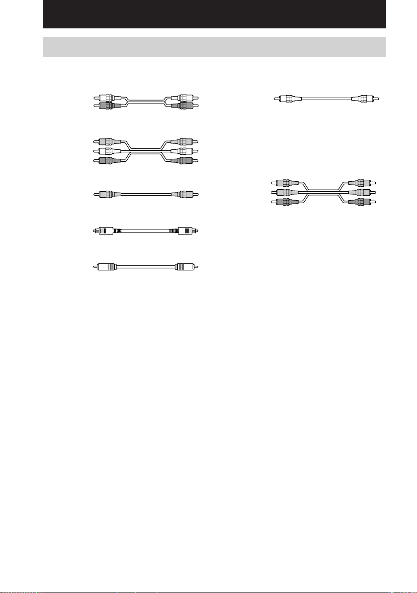
連接單片機
所需導線
當您連接組成機時,需要下列供選擇的連接電纜 A - G (第 8-11 頁)。
A 聲頻導線(無附帶)
白色(左)
紅色(右)
B 聲∕視頻導線(無附帶)
黃色(視頻)
白色(左聲頻)
紅色(右聲頻)
F 單聲道聲頻導線(無附帶)
黑色
要領
聲頻導線 A 可以撕成兩條單聲道聲頻導線
F。
G 單片機視頻導線(無附帶)
(STR-DE595 型號為限,地區碼 CEL,CEK
的型號除外)
C 視頻導線(無附帶)
黃色
D 光頻數字導線(無附帶)
E 同軸數字導線(無附帶)
綠色
藍色
紅色
要連接以前
• 要進行任何連接以前,必須先關掉所有單片機的電源。
• 未完成所有的連接工作以前,請勿連接 AC 電源導線。
• 接線必須穩固以免引起哼聲和噪音。
• 連接聲∕視頻導線時,導線的色碼管腳務必對準單片機上相應的插孔:黃色(視頻)對
黃色;白色(左聲頻)對白色;和紅色(右聲頻)對紅色。
• 當您連接光頻數字導線時,請插入導線插頭直至妥善就位。
• 不可彎折或打結光頻數字導線。
CS
6
Page 54
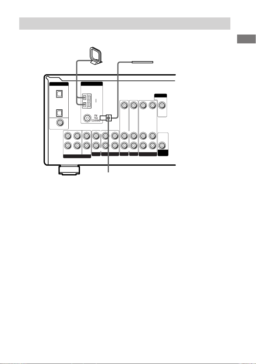
天線連接
AM 環形天線
(附帶)
連接單片機
FM 電線天線
(附帶)
L
R
MULTI CH IN
ANTENNA
CENTER
SUB
WOOFER
CD/SACD
AM
y
LRL
IN OUT
R
DIGITAL
OPTICAL
VIDEO 2
IN
CD/
SACD
IN
DVD IN
COAXIAL
FRONT SURROUND
*
* 連接器的形狀因地區碼而異。
天線連接需知
• 為防噪音干擾,請將 AM 環形天線遠離接收
機和其他單片機。
• FM 電線天線一定要完全伸開。
• 連接了 FM 電線天線之后,盡可能讓它保持
水平狀態。
MONITOR
VIDEO IN VIDEO IN VIDEO OUT VIDEO IN VIDEO OUT
AUDIO IN AUDIO IN
IN
DVDMD/TAPE
L
R
VIDEO 2
L
R
AUDIO OUT
AUDIO IN
VIDEO 1
AUDIO
OUT
SUB
WOOFER
CS
7
Page 55
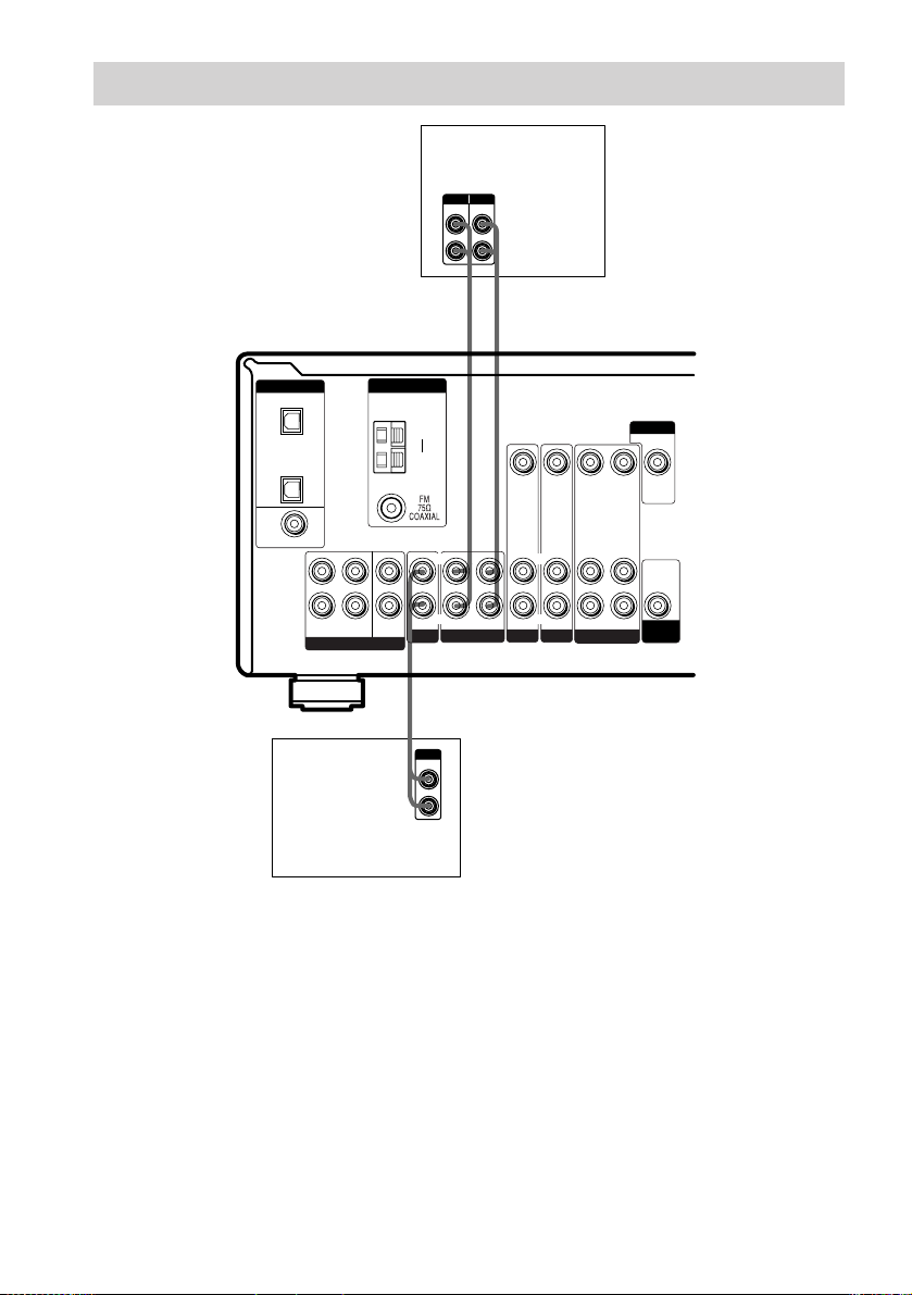
聲頻單片機的連接
MD/磁帶卡座
INPUT OUTPUT
LINE
LINE
L
R
AA
ç
ç
INOUT
* STR-DE595 型號為限。
DIGITAL
OPTICAL
VIDEO 2
IN
CD/
SACD
IN
DVD IN
COAXIAL
L
R
FRONT SURROUND
MULTI CH IN
CD 或 Super Audio
CD* 唱機
ANTENNA
CENTER
SUB
WOOFER
CD/SACD
AM
y
LRL
IN OUT
A
OUTPUT
LINE
MONITOR
VIDEO IN VIDEO IN VIDEO OUT VIDEO IN VIDEO OUT
L
R
L
R
AUDIO IN AUDIO IN
IN
DVDMD/TAPE
R
VIDEO 2
L
R
AUDIO OUT
AUDIO IN
VIDEO 1
AUDIO
OUT
SUB
WOOFER
CS
8
Page 56
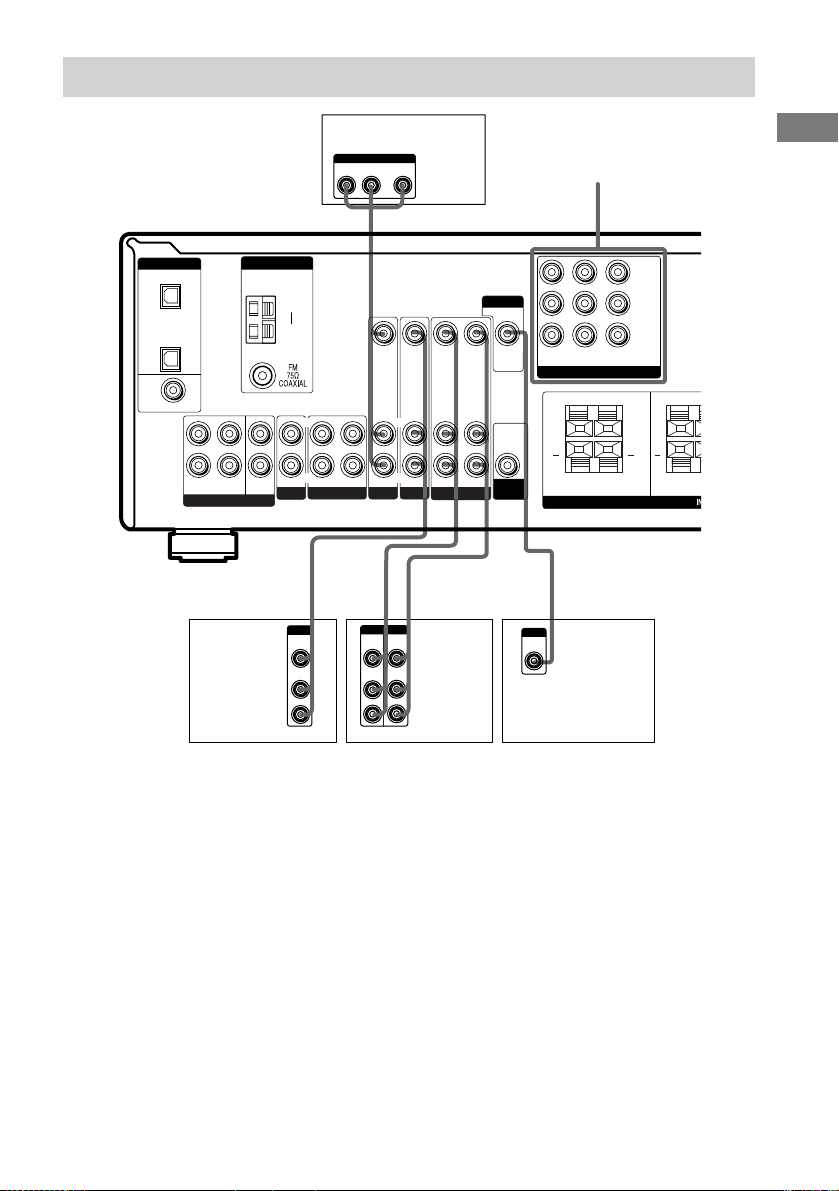
T
視頻單片機的連接
DIGITAL
OPTICAL
VIDEO 2
IN
CD/
SACD
IN
DVD IN
COAXIAL
ANTENNA
L
CENTER
R
MULTI CH IN
SUB
WOOFER
FRONT SURROUND
衛星調諧器
或錄影機
AM
y
IN OUT
CD/SACD
Ç
IN
B
OUTPUT
VIDEO
OUT
AUDIO
OUT
LRL
L
R
DVD 播放機
OUTPUT
AUDIO OUT VIDEO
L
OUT
R
B G
MONITOR
VIDEO IN VIDEO IN VIDEO OUT VIDEO IN VIDEO OUT
L
R
R
AUDIO IN AUDIO IN
IN
DVDMD/TAPE
Ç
BB
OUTPUTINPUT
VIDEO
VIDEO
OUT
IN
AUDIO
AUDIO
OUT
IN
VIDEO 2
Ç
L
R
L
R
AUDIO OUT
VIDEO 1
INOUT
錄影機
AUDIO IN
AUDIO
OUT
SUB
WOOFER
COMPONENT VIDEO*
DVD IN VIDEO 2INMONITOR
COMPONENT VIDEO
+ + +
INPUT
VIDEO
IN
OUT
RRL
L
FRONT B FRON
C
電視監視器
Y
P
B
/B—Y
P
R
/R—Y
SPEAKERS
連接單片機
R
R
* STR-DE595 型號為限,地區碼 CEL,CEK 的型號除外。
視頻單片機的連接需知
您可將電視機的聲頻輸出插孔連接到接收機
的 VIDEO 2 AUDIO IN 插孔,以增強電視聲
頻的音響效果。此時,請勿將電視機的視頻
輸出插孔連接到接收機的 VIDEO 2 VIDEO
IN 插孔。若您連接一台獨立的衛星調諧
器,請如上圖所示將聲視頻輸出插孔皆連接
到接收機上。
STR-DE595 型號為限,地區碼 CEL,CEK 的
型號除外
如果您的 DVD 播放機,電視機或衛星調諧
器帶有 COMPONENT VIDEO(Y,B-Y,R-Y)
輸出插孔,監視器則帶有 COMPONENT VIDEO
輸入插孔時,請用單片機視頻導線(無附
帶)連接到接收機。
CS
9
Page 57
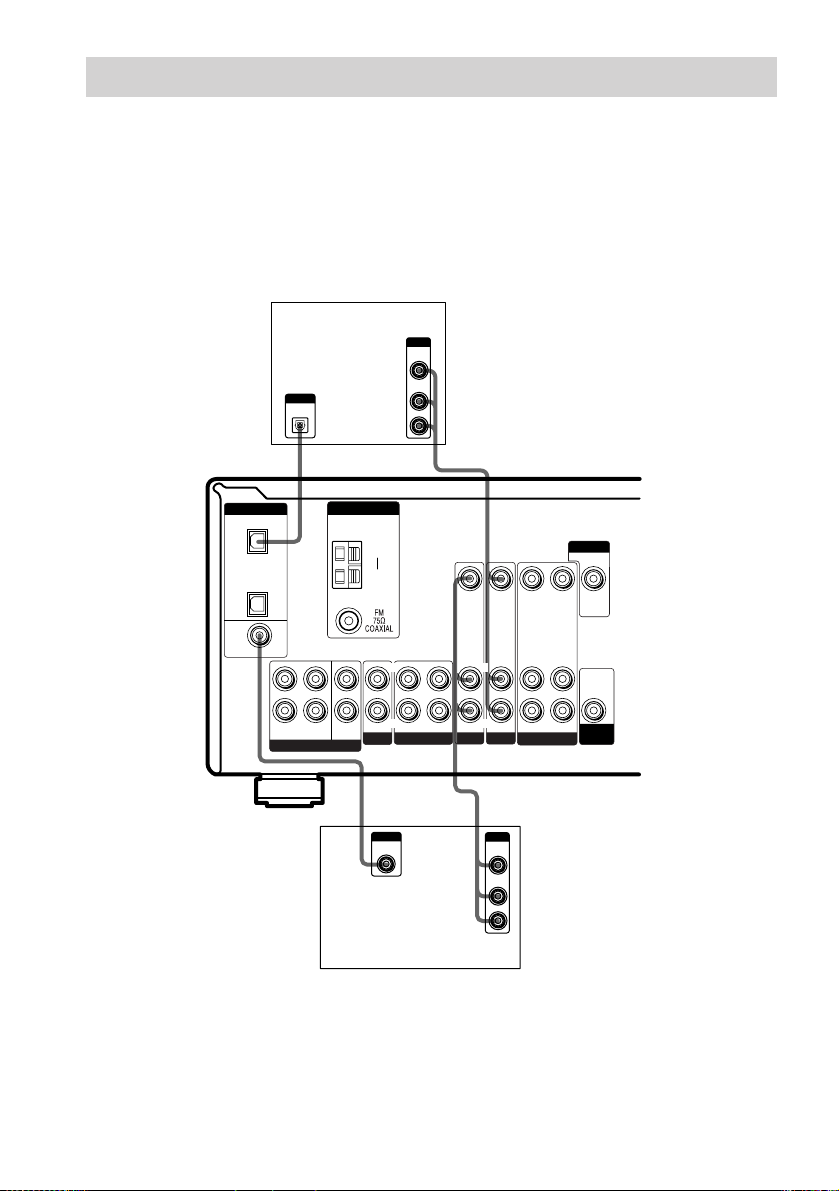
數字單片機的連接
將 DVD 播放機和衛星調諧器(等)的數字輸出插孔連接到接收機的數字輸入插孔,即可將電影
院的多重聲道環繞聲音響帶進您家裡。為了充分享受多重聲道環繞聲效果,您必須連接 5 台
揚聲器 (2 台前揚聲器,2 台環繞聲揚聲器和 1 台中央揚聲器) 和 1 台重低音揚聲器。
註
• 所有的 OPTICAL 和 COAXIAL 插孔皆與 96 kHz,48 kHz,44.1 kHz 和 32 kHz 取樣頻率兼容。
• (STR-DE595 型號為限) 在連接于本機的 CD/SACD OPTICAL IN 插孔的 Super Audio CD 唱機上播放
Super Audio CD 光碟時將沒有聲音輸出。請連接到模擬輸入插孔 (CD/SACD IN 插孔)。請參考附帶于
Super Audio CD 唱機的使用說明書。
DIGITAL
OPTICAL
VIDEO 2
IN
CD/
SACD
IN
DVD IN
COAXIAL
衛星調諧器或
DVD 播放機*
OUTPUT
DIGITAL
OPTICAL
ANTENNA
L
CENTER
R
MULTI CH IN
SUB
WOOFER
FRONT SURROUND
DVD 播放機(等)*
AM
y
IN OUT
CD/SACD
E
OUTPUT
DIGITAL
COAXIAL
OUTPUT
VIDEO
AUDIO
LRL
OUT
OUT
L
R
BD
VIDEO IN VIDEO IN VIDEO OUT VIDEO IN VIDEO OUT
L
R
R
AUDIO IN AUDIO IN
IN
DVDMD/TAPE
VIDEO 2
AUDIO OUT
B
OUTPUT
VIDEO
OUT
AUDIO
OUT
L
R
L
R
VIDEO 1
MONITOR
AUDIO IN
AUDIO
OUT
SUB
WOOFER
* 您可進行同軸或光頻連接。我們建議您採用同軸連接,而非光頻連接。
CS
10
Page 58
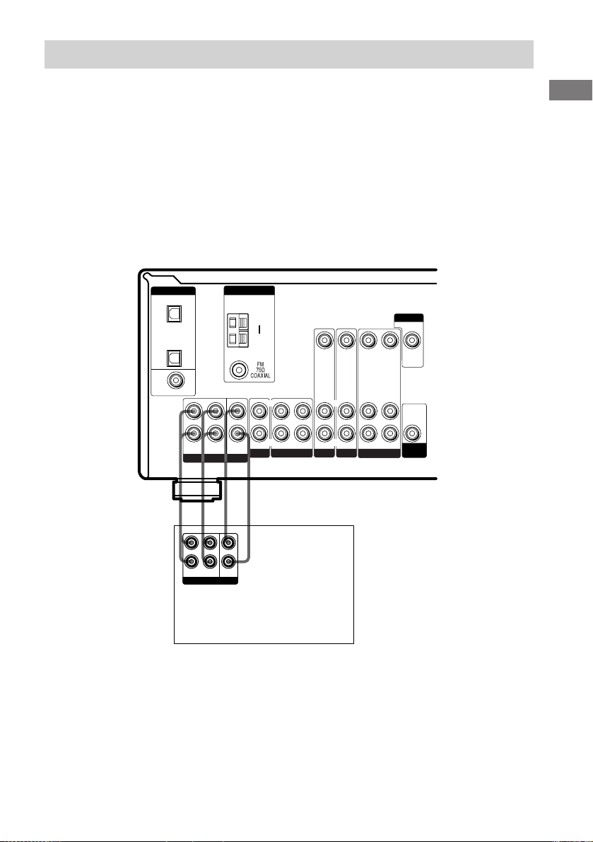
多重聲道輸入的連接
STR-DE595 型號為限
本接收機雖含有多重聲道解碼器,它也配備多重聲道輸入插孔。這些連接可讓您享受以杜比
數字 (Dolby Digital)和 DTS 格式以外編碼的多重聲道軟體。您的 DVD 播放機如果配備有多重
聲道輸出插孔,您便可將它們直接連接到接收機享受 DVD 播放機的多重聲道解碼器的音響。
另外,多重聲道輸入插孔還可用于連接外接式多重聲道解碼器。
為了充分享受多重聲道環繞聲效果,您必須連接 5 台揚聲器 (2 台前揚聲器,2 台環繞聲揚聲
器和 1 台中央揚聲器) 和 1 台重低音揚聲器。有關多重聲道連接的詳細內容,請參考隨 DVD
播放機,多重聲道解碼器等附帶的使用說明書。
註
• 採用下述連接時,請調整 DVD 播放機或多重聲道解碼器的環繞聲揚聲器和重低音揚聲器的電平。
• 有關揚聲器系統之連接詳情,請參看第 13 頁。
連接單片機
DIGITAL
OPTICAL
VIDEO 2
IN
CD/
SACD
IN
DVD IN
COAXIAL
ANTENNA
L
CENTER
R
MULTI CH IN
SUB
WOOFER
FRONT SURROUND
AFAF
L
R
FRONT
SURROUND
MULTI CH OUT
CENTER
SUB
WOOFER
DVD 播放機,
多重聲道解碼器等。
AM
y
IN OUT
CD/SACD
LRL
VIDEO IN VIDEO IN VIDEO OUT VIDEO IN VIDEO OUT
L
R
AUDIO IN AUDIO IN
IN
DVDMD/TAPE
R
VIDEO 2
AUDIO OUT
VIDEO 1
L
R
AUDIO IN
MONITOR
AUDIO
OUT
SUB
WOOFER
11
CS
Page 59
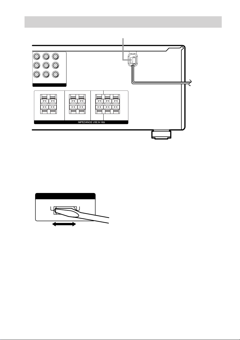
其他連接
Y
P
B
/B—Y
P
R
/R—Y
DVD IN VIDEO 2
MONITOR
OUT
IN
COMPONENT VIDEO
RRL
+
—
L
FRONT B FRONT A CENTER SURROUND
RRL
+—+
—
L
SPEAKERS
+—+
AC 電源線
b
RRL
+
—
—
L
至牆上插座
設定電壓選擇器
如果接收機的后面板上有電壓選擇器,請查
看電壓選擇器的設置是否符合當地電壓標
準。若不,在連接 AC 電源線至牆上插座以
前,請用螺絲起子把選擇器設定于正確的位
置。
VOLTAGE SELECTORVOLTAGE SELECTOR
120V
220V 240V
連接 AC 電源線
要將本接收機的 AC 電源線接插到牆上插座
之前,請先把揚聲器系統連接到接收機 (第
13 頁)。
將聲∕視頻單片機的 AC 電源線接插到牆上
插座。
12
CS
Page 60

連接和設置揚聲器系統
連接揚聲器系統
需用導線
A 揚聲器導線(無附帶)
(+)
(-)
B 單聲道聲頻導線(無附帶)
黑色
連接和設置揚聲器系統
有源重低音揚聲器
INPUT
AUDIO
IN
B
MONITOR
VIDEO OUT
DVD IN VIDEO 2INMONITOR
COMPONENT VIDEO
AUDIO
OUT
SUB
WOOFER
A
E
前揚聲器(右)
Ee
A
Y
P
B/B—Y
P
R/R—Y
OUT
RRL
L
FRONT B FRONT A CENTER SURROUND
e
RRL
L
SPEAKERS
AA
E
e
RRL
L
E
前揚聲器(左)
E
A
e
E
e
A
e
E
A
e
前揚聲器 B*
(右)
前揚聲器 B*
(左)
中央揚聲器
環繞聲揚聲器
(右)
環繞聲揚聲器
(左)
* (STR-DE595 型號為限) 如果您有一台額外的前揚聲器系統,請將它連接至 SPEAKERS FRONT B 端子。
您可用 SPEAKERS (OFF/A/B/A+B) 按鈕選擇您想要用的前揚聲器 (第 22 頁)。
接下頁
13
CS
Page 61
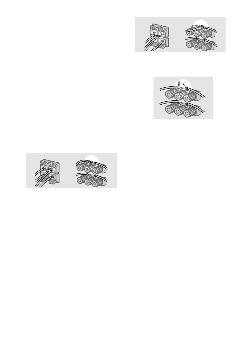
連接揚聲器系統 (續)
註
• 將揚聲器導線剝除絕緣的一端扭曲約 10 mm。
務必將揚聲器導線對準單片機上相應的端子來
接插:+ 至 + 及 - 至 - 。如果接反了導線,聲
音將失真並缺乏低音。
• 如果使用低于最大輸入定額的揚聲器,請小心
調節音量以免超出揚聲器的輸出定額。
為免揚聲器發生短路
揚聲器發生短路可能會損壞接收機。為防此
事故,連接揚聲器時必須注意下列事項。
請確保每條揚聲器導線已剝過的尾端沒有觸碰
到其他揚聲器端子、其他揚聲器已剝過的尾端
或接收機的金屬部件。
狀況欠佳的揚聲器導線範例
剝除了絕緣皮的揚聲器導線觸碰到別的揚聲器
端子。
過分剝除絕緣部分導致剝除了絕緣的導線相互
觸碰。
剝除了絕緣的導線未完全連接並觸碰到接收機
的后面板。
連接好所有單片機,揚聲器和 AC 電源線之
后,請輸出測試音以檢查所有的揚聲器是否都
已正確地連接。有關輸出測試音的詳情,請參
照第 20 頁。
輸出測試音時,若聽不到聲音自揚聲器發
出,或者,測試音並非從接收機正顯示著名
稱的揚聲器發出時,可能是揚聲器發生短
路。遇此情況時,請再次檢查揚聲器的連
接。
要避免損壞您的揚聲器時
請確保在關閉接收機以前先調低接收機的音
量。當您打開接收機,音量應該保持在您關
閉接收機時的水平。
14
CS
Page 62
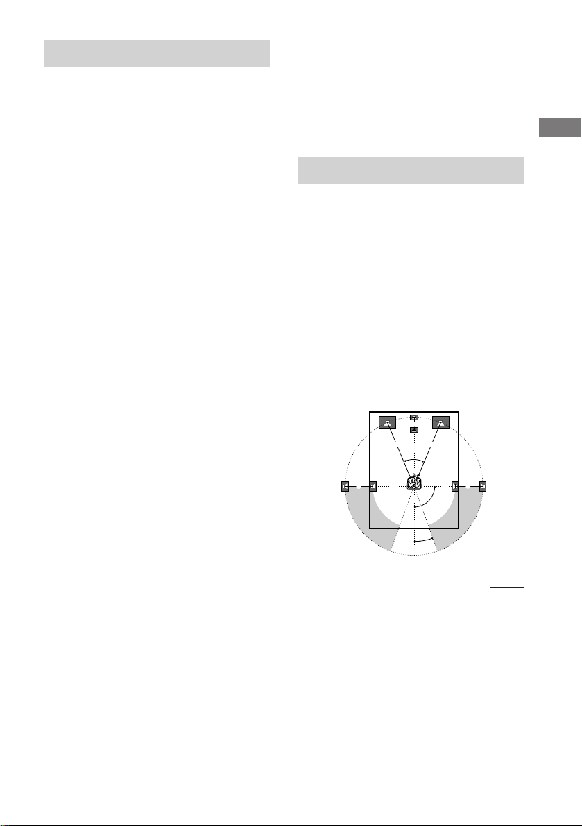
執行初始設置操作
45°
90°
20°
A A
B
CC
一旦連接了揚聲器並打開電源后,請清除接
收機的存儲。然后,請指定揚聲器參數 (大
小,位置等)並執行您的系統所需的任何其
他初始設置。
要領
設定中查聽聲頻輸出 (輸出聲音時進行設置),檢
查連接狀態 (第 20 頁)。
執行初始設置操作
第一次使用您的接收機之前,請先調整 SET
UP 參數使接收機相應于您的系統。有關可
調整參數,請參看第 47 頁的桌表。關于揚
聲器的設定,請參看第 15-20 頁。有關其他
設定,則請參看第 35-36 頁。
連接和設置揚聲器系統
多重聲道環繞聲的設置
清除接收機的存儲
首次使用接收機或要清除接收機的存儲時,
請進行下列程序。
1 關掉接收機。
2 按住 ?/1 5秒。
“INITIAL”(初始)出現在顯示器中。
下面是重調為工廠設定項。
• SET UP,LEVEL,和 TONE 菜單中的
所有設定。
• 各功能和預約電台的所記憶的聲場。
• 所有的聲場參數。
• 所有的預約電台。
• 所有輸入選擇器和預約電台的索引
名。
• 主音量被設定為“VOL MIN”。
為獲得最佳的環繞聲效果,所有的揚聲器必
須與聆聽位置 A 具同等距離。
然而,接收機卻允許您將中央揚聲器更接近
B 聆聽位置放置;即高達 1.5 米,而環繞
聲揚聲器則 4.5 米更接近 C 聆聽位置。
前揚聲器可被安置在離聆聽位置 A 1.0 至
7.0 米(3 至 23 英尺)之處。
您可依據房間的形狀將環繞聲揚聲器放置在
您的后面或兩側。但是,我們建議您將環繞
聲揚聲器放置于您身后。
當放置環繞聲揚聲器于您的兩側時
(長型房間)
接下頁
CS
15
Page 63
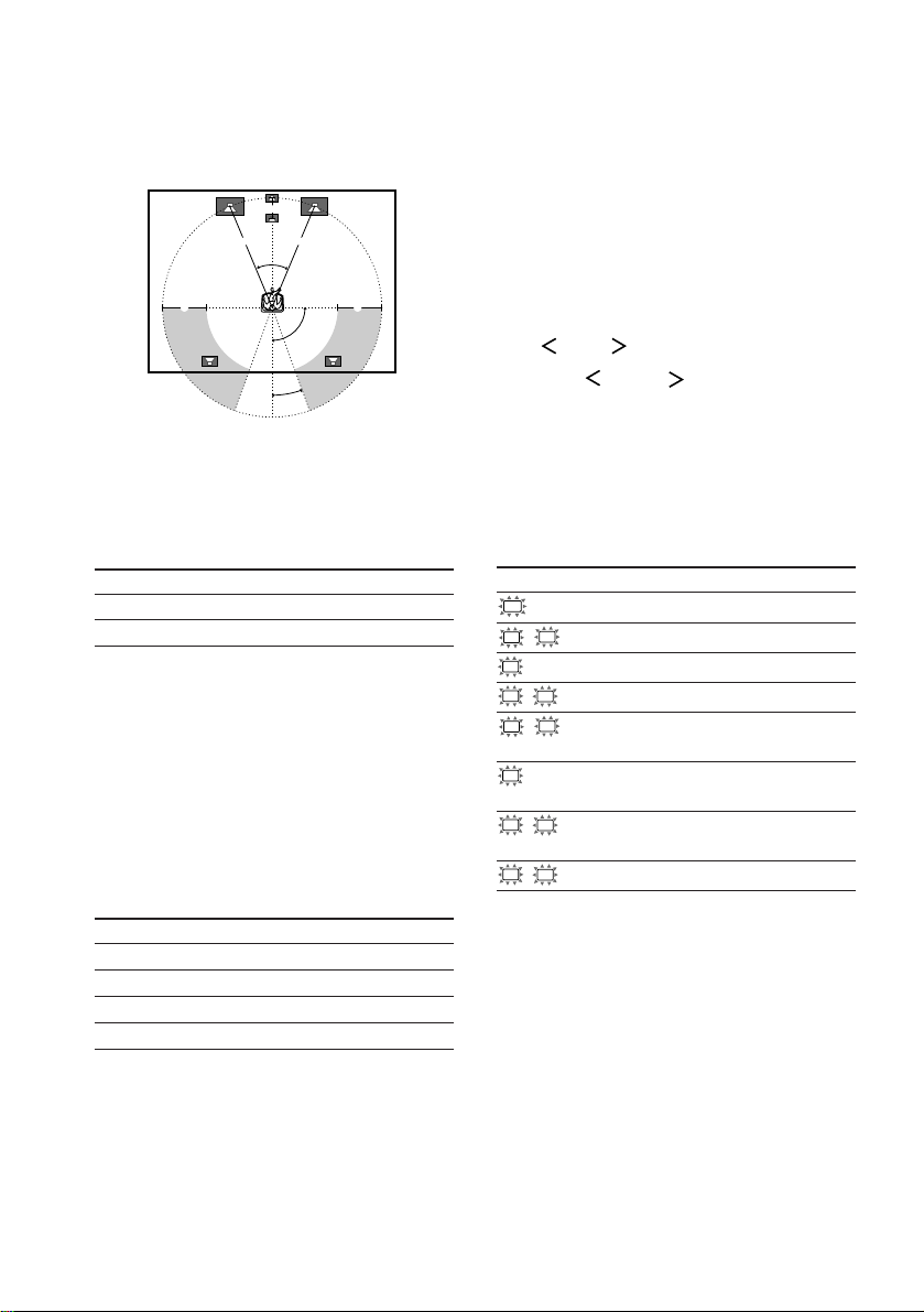
多重聲道環繞聲的設置 (續)
當放置環繞聲揚聲器于您的后面時
註
請勿將中央揚聲器放置在比前揚聲器距離聆聽位
置更遠處。
(寬型房間)
B
A A
45°
20°
CC
90°
一般揚聲器和微衛星揚聲器
若您正在使用 請選擇
一般揚聲器 NORM. SP.
微衛星揚聲器 MICRO SP.
揚聲器的尺寸和重低音揚聲器的選項已被預
設為“NORM. SP.”。當您選擇了“NORM.
SP.”(第 17 頁),您即可調整揚聲器的尺
寸和重低音揚聲器的選項。
要選擇“MICRO SP.”時,先關閉電源,然
后在按住 MAIN MENU 時再次打開。(要重新
設定為 “NORM. SP.”時,請進行同樣的步
驟。)
若您選擇“MICRO SP.”,揚聲器的尺寸和
重低音揚聲器的選項則被定製如下:
揚聲器 設定
FRONT SMALL(小)
CENTER SMALL(小)
SURROUND SMALL(小)
SUB WOOFER YES(是)
要領
微衛星揚聲器 (MICRO SP.) 的設置被編程以使音
響平衡更為理想。若您使用 Sony 的微衛星揚聲
器,請選擇“MICRO SP.”。
小心
當您使用微衛星揚聲器,而揚聲器尺寸被設置為
“LARGE”時,您可能無法獲取正確的聲階。揚聲
器也可能因為處于高音量而損壞。
指定揚聲器參數
1 反複按 MAIN MENU(主選單)以選擇
“ SET UP ”(設定)。
2 按 MENU 或 MENU 以選擇所要調整的參
數。
3 按 MENU + 或 MENU - 以選擇所要的設定。
設定即自動地被輸入。
4 反複步驟 2 和 3 直至設定好下列所有的參
數。
初始設定
參數 初始設定
SW
(SUB WOOFER) S.W. XXX YES*
L
R (FRONT) XXXXX LARGE*
C
(CENTER) XXXXX LARGE*
SL
SR (SURROUND) XXXXX LARGE*
L
R DIST. X.X m (XX ft.)** 3.0 m
(10 ft.)**
C
DIST. X.X m (XX ft.)** 3.0 m
(10 ft.)**
SL
SR DIST. X.X m (XX ft.)** 3.0 m
(10 ft.)**
SL
SR PL. XXXX LOW
* 僅當選取“NORM.SP.”方可設置此參數。
** 地區碼為 U,CA 的型號預設單元為“ft.”。
其他地區碼的型號的預設單元為“m”。
選擇“MICRO SP.”將使您無法更換揚聲器的結
構。
CS
16
Page 64
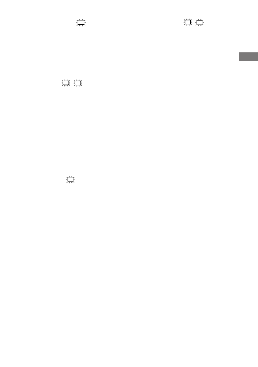
x 重低音揚聲器的選項 (SW S.W. XXX)
• 如果連接重低音揚聲器,請選擇“YES ”。
• 如果沒有連接重低音揚聲器,請選擇
“NO”。這將啟動低音改向電路並從別的揚
聲器輸出 LFE 信號。
• 為了充分利用杜比數字(Dolby Digital)
低音改向電路,我們建議您把重低音揚聲器
的截斷頻率盡可能設定于較高頻率。
x 前揚聲器尺寸 (L R XXXXX)
• 如果連接了可有效地再現低音頻率的大型揚
聲器,請選擇“LARGE”(大型)。通常是選
“LARGE”。
• 使用多重聲道環繞聲時如果聲音失真,或缺
乏環繞聲效果,請選擇“SMALL”(小型) 以
啟動低音改向電路並從重低音揚聲器輸出前
聲道低音頻率。
• 當前揚聲器被設定為“SMALL”時,中央和
環繞聲揚聲器也都自動地設定為“SMALL”
(除非預先設定于“NO”)。
• 當重低音揚聲設定為“NO”,前揚聲器自動
設定為“LARGE”(大型),並且您無法改
變此設定。
x 中央揚聲器尺寸 (C XXXXX)
• 如果連接了可有效地再現低音頻率的大型揚
聲器,請選擇“LARGE”(大型)。通常是選
“LARGE”。然而,如果設定前揚聲器于
“SMALL”,您將無法把中央揚聲器設定于
“LARGE”。
• 使用多重聲道環繞聲時如果聲音失真,或缺
乏環繞聲效果,請選擇“SMALL”以啟動低
音改向電路並從前揚聲器 (如果設定于
“LARGE”) 或重低音揚聲器輸出中央聲道
低音頻率。*
• 如果沒有連接中央揚聲器,請選擇“NO”。
中央聲道的音響將從前揚聲器輸出。*
1
2
x 環繞聲揚聲器尺寸 (SL SR XXXXX)
• 如果連接了可有效地再現低音頻率的大型揚
聲器,請選擇“LARGE”(大型)。通常是選
“LARGE”。然而,如果設定前揚聲器于
“SMALL”,您將無法把環繞聲揚聲器設定
于“LARGE”。
• 使用多重聲道環繞聲時如果聲音失真,或缺
乏環繞聲效果,請選擇“SMALL”以啟動低
音改向電路並從重低音揚聲器或“LARGE”
揚聲器輸出環繞聲聲道低音頻率。
• 如果沒有連接環繞聲揚聲器,請選擇
“NO”。*
要領
*1–*3 相應于下列杜比專業邏輯(Dolby Pro
Logic)模式
*1 NORMAL (一般)
*2 PHANTOM (幻像)
*3 3 STEREO (3 立體聲)
3
接下頁
連接和設置揚聲器系統
17
CS
Page 65

多重聲道環繞聲的設置 (續)
要領
每台揚聲器的 LARGE 和 SMALL 設置將決定內置
音響處理器是否將截斷來自該聲道的低音信號。
當低音被截斷后,低音改向電路將傳送相應的低
音頻率至重低音揚聲器或其他“LARGE”揚聲器。
然而,因為低音含有指定的改向性質,可以的話
最好別截斷它。因此,雖然使用小型揚聲器,若
您要從該揚聲器輸出低音頻率,您可將它設置為
“LARGE”。另一方面,若您使用大型揚聲器但卻
不希望低音頻率自揚聲器輸出,則請設置為
“SMALL”。
如果總聲音電平低于您所要的水準,請把所有的
揚聲器都設定于“LARGE”。如果低音不足,您可
使用 TONE(音調)選單裡的 BASS(低音)參數
以加強低音電平。請參看第 28 頁以調整低音。
x 前揚聲器的距離(L R DIST. X.X m
(XX ft.))
設定從您的聆聽位置到前揚聲器的距離(第
15 頁的 A)。
x 中央揚聲器的距離 (C DIST. X.X m
(XX ft.))
設定從您的聆聽位置到中央揚聲器的距離。
中央揚聲器的距離必須與前揚聲器(第 15
頁的 A)的距離一樣;即 1.5 米更接近您
的聆聽位置(第 15 頁的 B)。
要領
接收機可讓您按照距離輸入揚聲器的位置。然
而,您不能把中央揚聲器設定得更遠于前揚聲
器。中央揚聲器也不能設定在 1.5 米以上更接近
于前揚聲器。
同樣的,環繞聲揚聲器不可設置在比前揚聲器更遠
于聆聽位置。而且,它們不可被放置在超過
4.5 米更接近聆聽位置。這是因為錯誤放置揚聲器
將使您無法充份享受環繞聲效果。
請注意,揚聲器的距離設定如果近過揚聲器的實際
位置,則來自揚聲器的音響將會被延遲。換言之,
揚聲器聽起來會好像遠一些。
例如把中央揚聲器的距離設定得比實際的揚聲器位
置近 1∼2 米時將製造相當逼真的“在銀幕裡面”
的感覺。如果因為環繞聲揚聲器太靠近而得不到滿
意的環繞聲效果,您可以把環繞聲揚聲器的距離設
定為比實際距離接近(較短距離),如此即可產生較
大聲級。
一邊聆聽音響一邊調節這些參數將帶給您更佳的
環繞聲效果。不妨試試!
x 環繞聲揚聲器的距離 (SL SR DIST. X.
X m (XX ft.))
設定從您的聆聽位置到環繞聲揚聲器的距
離。環繞聲揚聲器的距離必須與前揚聲器
(第 15 頁的 A)的距離一樣;即 4.5 米
更接近您的聆聽位置(第 15 頁的 C)。
CS
18
Page 66
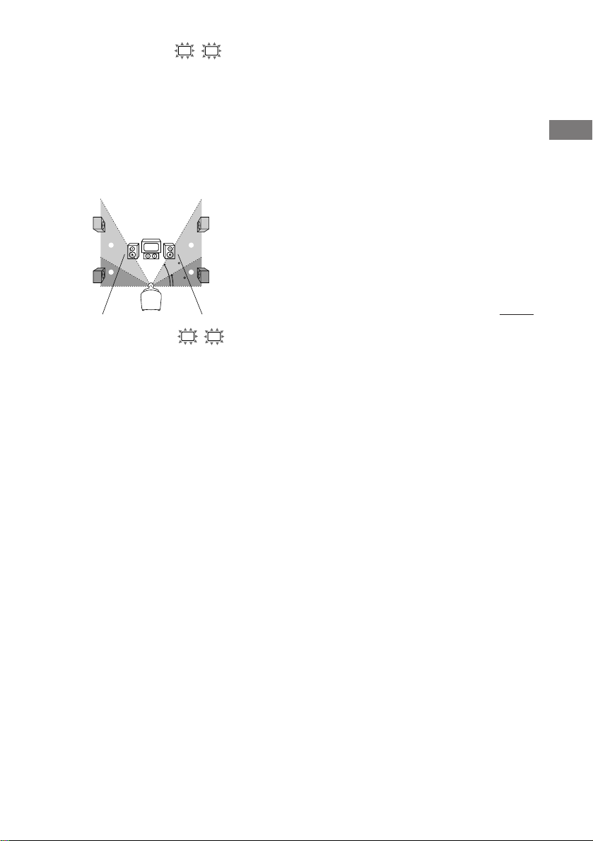
x 環繞聲揚聲器的放置 (SL
SR
PL. XXXX)*
此參數可讓您指定環繞聲揚聲器的高度以正
確地操作數字影院音響環繞聲模式。請參考
下圖。
• 如果環繞聲揚聲器的位置符合 A 部分,請
選擇“PL. LOW”。
• 如果環繞聲揚聲器的位置符合 B 部分,請
選擇“PL. HIGH”。
B
A
B
60
A
30
* 當“環繞聲揚聲器尺寸 (SL SR)”被設定
于“NO”時,這些參數都無效。
要領
環繞聲揚聲器的放置參數是為操作帶有虛擬元素
的數字影院音響模式而設計的。
在數字影院音響模式中,揚聲器的放置將不像其
他模式所要求的的那樣嚴格。所有具有虛擬元素
的模式雖都以環繞聲揚聲器必須被設置在聆聽位
置后面的前提下設計,但即使環繞聲揚聲器位于
相當寬大的角度,它仍能保留相當的效果。但
是,如果揚聲器從緊靠著聆聽位置的左邊和右邊
面對聆聽者時,帶有虛擬元素的揚聲將無法發揮
功效。
此外,每個聆聽環境都有許多可變因素,例如牆
的反射性。
因此,我們建議您播放多重聲道環繞聲編碼軟
件,並且于您所在之處聆聽每個設定的效果。請
選擇那些有良好的寬廣感,以及在環繞聲揚聲器
的環繞音響和前揚聲器的聲響之間能最成功組成
一連貫空間的設置。若您不確定那種音響最好,
請選擇“PL. LOW”,然后使用揚聲器距離參數和
揚聲器電平調整以獲得適當的平衡。
接下頁
連接和設置揚聲器系統
19
CS
Page 67

多重聲道環繞聲的設置 (續)
檢查連接
調整揚聲器的電平
坐在聆聽位置時用遙控器調整各揚聲器的電
平。
註
本接收機含有中心頻率為 800 Hz 的全新音響,讓
您更輕易地調整揚聲器電平。
1 按遙控器上的 ?/1 以打開接收機。
2 按遙控器上的 TEST TONE。
顯示器中即出現“T. TONE”(測試音),
您將逐一地從各個揚聲器聽到測試音。
前 (左) t 中央 t 前 (右) t
環繞 (右) t 環繞 (左) t
重低音揚聲器
3 利用 LEVEL(電平)菜單調整揚聲器電平
和平衡,使來自各揚聲器的測試音大小水
平相同。
有關 LEVEL 選單的詳情,請參看第 27
頁。
在進行調整當中,測試音是從被調整的
揚聲器所輸出。
4 再按一次 TEST TONE 以關掉測試音。
要領
您可同時調整所有揚聲器的電平。按遙控器上的
MASTER VOL +/- 或轉動主機上的 MASTER VOLUME。
註
• (STR-DE595 型號為限) 當接收機被設定為
MULTI CH IN 時將無法輸出測試音。
• 在進行調整當中,調整數值將顯示于顯示器。
• 雖然這些調整也可用前面板上的 LEVEL 選單來
進行(當輸出測試音時,接收機將自動地切換
為 LEVEL 選單),我們建議您按照上述說明,
用遙控器從您的聆聽位置調整揚聲器的電平。
把所有的單片機都連接到接收機之后,請進
行下列操作以確認連接是否正確。
1 按 ?/1 以打開接收機。
2 打開所連接的單片機(例如 CD 唱機或磁帶
卡座)。
3 按輸入選擇器按鈕(例如 CD∕SACD
(STR-DE595 型號為限)∕CD(STR-DE495
型號為限)或 MD∕TAPE)以選擇單片機
(節目信號源)。
4 開始播放。
若進行這些步驟以后仍無法獲得正常的音
響,請參看第 41 頁的“故障探尋”以採取
適當的對策。
20
CS
Page 68
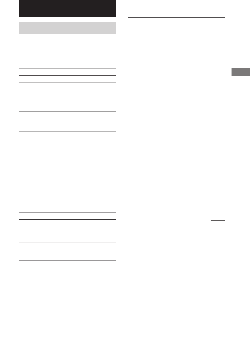
基本操作
選擇單片機
輸入選擇器按鈕
按輸入選擇器按鈕以選擇您要使用的單片
機。
要選擇 按
錄影機 VIDEO 1 或 VIDEO 2
衛星調諧器 VIDEO 2
DVD 播放機 DVD
MD 或磁帶卡座 MD/TAPE
CD 唱機 CD (STR-DE495 型號為限)
CD 或 Super Audio CD/SACD
CD 唱機 (STR-DE595 型號為限)
內置調諧器 TUNER FM/AM
打開所選單片機之后,選擇單片機並播放節
目信號源。
• 選擇了錄影機或 DVD 播放機之后,打開電
視機並設定電視機的視頻輸入以配合您所選
的單片機。
選擇 以便
OPT IN 指定數字聲頻信號輸入到
DIGITAL OPTICAL 輸入插
孔。
ANALOG 指定模擬聲頻信號輸入到
AUDIO IN (L/R) 插孔。
註
當 96 kHz 數字信號被輸入,音調,聲場和環繞
聲效果將不起作用。
MULTI CH IN
(STR-DE595 型號為限)
按 MULTI CH IN 以享受連接到 MULTI CH
IN 插孔的聲頻源。您可以調整所有揚聲器
的平衡和電平。當此功能啟動,音調和環繞
聲效果將關閉。
MULTI CHANNEL DECODING (多重聲道解
碼) 指示燈
(STR-DE595 型號為限)
當本機給用多重聲道格式錄音的信號解碼
時,此指示燈將亮起。
基本操作
輸入模式
按 INPUT MODE 為數字單片機選擇輸入模
式。
每按一次按鈕,當前所選單片機的輸入模式
將轉換。
選擇 以便
AUTO IN 當兼具數字和模擬兩種連
接時,數字信號具有優先
權。如果沒有數字信號,
模擬將被選取。
COAX IN 指定數字聲頻信號輸入到
DIGITAL COAXIAL 輸入插
孔。
MUTING (靜音)
按下遙控器上的 MUTING 以消除聲音。再次
按下以取消靜音功能。當您打開電源或轉動
MASTER VOLUME 以提高音量時,靜音功能也
將被取消。
接下頁
21
CS
Page 69

選擇單片機 (續)
改變顯示
PHONES (耳機)
用于連接頭戴耳機。
• 當連接了頭戴耳機時,揚聲器的輸出將自動
取消,“SP”(STR-DE495 型號為限) 或“SP
A”和“SP B”(STR-DE595 型號為限) 將不
會在顯示器中亮起。
SPEAKERS (OFF/A/B/A+B)
(STR-DE595 型號為限)
按 SPEAKERS (OFF/A/B/A+B) 按鈕以從連接
到 SPEAKERS FRONT 端子的揚聲器輸出聲
音。
每次您按下按鈕,顯示器將如下般循環亮
起:
SP A t SP B t SP A 和 SP B t
無顯示*
要驅動 請選擇
揚聲器系統 A(連 SP A(出廠預設)
接至 SPEAKERS
FRONT A 端子)
揚聲器系統 B(連 SP B
接至 SPEAKERS
FRONT B 端子)
兩個揚聲器系統 SP A 和 SP B
A 和 B(連接至
SPEAKERS FRONT
A 和 B 端子)
DIMMER (調光器)
反複按 DIMMER 以調整顯示器的亮度
(3 段)。
然而,當按任何按鈕時,顯示將暫時變成最
亮的設定。
DISPLAY (顯示)
每按一次 DISPLAY,顯示即如下循環切換:
單片機的索引名稱* t 所選單片機 t 適
用于節目信號源的聲場
選取調諧器時
預約電台的索引名稱*或電台節目名稱**
t 頻率 t 節目類型指示** t 無線電廣
播文本** t 當前時間** t 適用于波段
或預約電台的聲場
* 索引名稱僅當在您已指配一個名稱給單片機或
預約電台后才會出現(第 34 頁)。只輸入空
白空間或與輸入選擇器具有同樣名稱將無法顯
示索引名稱。
** 僅當處于 RDS 接收時。(地區碼 CEL,CEK 的
型號為限。參看第 32 頁。)
* 如果您不想驅動揚聲器系統 A 和 B,按
SPEAKERS (OFF/A/B/A+B) 直到“SP A” 和
“SP B”在顯示器中無法亮起(無顯示)。
CS
22
Page 70

享受環繞聲
只需選擇接收機的預編程聲場之一,您即可
充份利用環繞聲效果。這些效果能將電影院
和音樂廳魄力十足及強勁的音響帶進您家
裡。您也可通過改換環繞聲參數來定製聲場
以獲取您所要的音響。
為能充分享受環繞聲效果,您必須先登記揚
聲器的數量和位置。享受環繞聲之前,請參
閱從第 15 頁起的“多重聲道環繞聲的設
置”一節以設定揚聲器參數。
僅使用前揚聲器 (2 聲道
立體聲)
按 2CH。
2CH(2 聲道)指示燈亮起,“2CH ST.”將
出現于顯示器中。
此模式只從前左和右揚聲器輸出聲音。標準
的 2 聲道(立體聲)信號源完全不需經過
聲場處理。多重聲道環繞聲格式將下降混頻
為 2 聲道。
註
• 當選取“2CH ST.”,重低音揚聲器將不輸出聲
音。如果要使用前左和右揚聲器以及重低音揚
聲器聆聽 2 聲道(立體聲)時,反複按
A.F.D.(自動格式化指令)以選擇“A.F.D.
AUTO”。
• 當選取“微衛星揚聲器”(第 16 頁),內置
音響處理器會自動地將低音轉至重低音揚聲
器。若您想要在此設定中聆聽 2 聲道(立體
聲)信號源,我們建議您選擇“A.F.D. AUTO”
模式。您可充分利用重低音揚聲器以獲得正確
的重低音信號。
享受高保真度音響
此自動格式化指令 (A.F.D.) 模式允許您為
聲頻音響選擇您想要的解碼模式。
模式 解碼模式
A.F.D. AUTO 與編碼相同
DOLBY PL 杜比專業邏輯
PLII MOV
PLII MUS
自動為輸入的聲頻信號解碼
反複按 A.F.D.(自動格式化指令)以選擇
“A.F.D. AUTO”。
A.F.D. (自動格式化指令) 指示燈將亮起。
本模式能自動檢測輸入的聲頻信號類型
(Dolby Digital,DTS 或標準 2 聲道立體
聲),必要時則執行適當的解碼。此模式將
輸出所錄制∕編碼的音響而不加雜其他效果
(例如交混回響)。
然而,若沒有低頻率信號 (Dolby Digital
LFE 等),它將製造低頻率信號以輸出到重
低音揚聲器。
杜比專業邏輯 II
接下頁
享受環繞聲
23
CS
Page 71

享受高保真度音響 (續)
選擇聲場
在多重聲道中享受立體聲音響(杜比
專業邏輯 )
此接收機結合了具有電影模式和音樂模式的
Dolby Pro Logic II (杜比專業邏輯 II)。
而且此接收機可通過 Dolby Pro Logic II
(杜比專業邏輯 II) 在 5.1 聲道中再現 2
聲道音響。
反複按 A.F.D.(自動格式化指令)以選擇
“DOLBY PL”,“PLII MOV”或
“PLII MUS”。
A.F.D.(自動格式化指令)指示燈將亮起,
所選擇的解碼類型將在顯示器中顯示。
x DOLBY PL (杜比專業邏輯)
執行專業邏輯解碼。具有多重聲道環繞聲聲
頻信號的軟體將依據其錄制方式播放。帶有
2 聲道聲頻信號的信號將用杜比專業邏輯解
碼以創造環繞聲效果(四聲道)。
x PLII MOV (專業邏輯 II 電影)
執行專業邏輯 II 電影模式解碼。此設定適
用于以杜比環繞聲編碼的電影。此外,在觀
看舊電影或配音的錄像帶時,可用此模式再
現 5.1 聲道聲。
x PLII MUS (專業邏輯 II 音樂)
執行專業邏輯 II 音樂模式解碼。此設定適
用于諸如 CD 等一般的立體聲信號源。
註
杜比專業邏輯和杜比專業邏輯 II 的解碼對于
DTS 格式的信號不起作用。
只需根據您所要收聽的節目選擇其中一種預
編程聲場,您便可享受環繞聲效果。
按 要選擇
MOVIE C.ST.EX A DCS *
C.ST.EX B DCS *
C.ST.EX C DCS *
MUSIC HALL
JAZZ
CONCERT
*帶 DCS 標誌的聲場採用 DCS 技術。
關于 DCS (數字影院音響)
在與 Sony Pictures Entertainment 的協作
下,Sony 掌握了製片的音響環境,並且結
合所測得的數據和 Sony 的 DSP (數字信號處
理器) 技術得以發展“Digital Cinema
Sound”(數字影院音響)。在家居影院中,
“Digital Cinema Sound”(數字影院音響)
將依據影片導演的偏好模仿理想的影院音響
環境。
用 Cinema Studio (影院製作室) EX 觀
賞電影
Cinema Studio (影院製作室) EX 是用于享受
用多重聲道格式編碼的電影軟件,諸如
Dolby Digital DVD (杜比數字 DVD)之類的理
想模式。此模式用于再現 Sony Pictures
Entertainment 製作室的音響特質。
反複按 MOVIE(電影)以選擇
“C.ST.EX A”,“C.ST.EX B”或
“C.ST.EX C”。
MOVIE(電影)指示燈將亮起,所選擇的聲
場出現于顯示器中。
24
CS
Page 72
x C.ST.EX A (影院製作室 EX A)
再現 Sony Pictures Entertainment 的
“Cary Grant Theater”影片製作室的音響
特質。這是一個標準模式,可以很好地觀看
大多數類型的影片。
x C.ST.EX B (影院製作室 EX B)
再現 Sony Pictures Entertainment 的
“Kim Novak Theater”影片製作室的音響特
質。此模式是用于觀看具有很多音響效果的
科幻或動作影片的理想模式。
x C.ST.EX C (影院製作室 EX C)
再現 Sony Pictures Entertainment 的配樂
劇的音響特質。此模式用于觀看音樂劇或音
軌中以音樂為特色的古典影片的理想模式。
關于 Cinema Studio (影院製作室) EX
Cinema Studio (影院製作室) EX 包括下列三
個要素:
• 虛擬多空間
從單一的實際環繞聲揚聲器製造 5 套虛擬
揚聲器圍繞著聽者。
• 屏幕深度配合
在電影院裡,音響彷彿來自投射在電影屏
幕上的影像的內部。此要素通過將前揚聲
器的音響轉換到屏幕上,在您的聆聽室裡
製造同樣的感覺。
• 影院製作室交混回響
再現電影院獨有的交混回響。
Cinema Studio (影院製作室) EX 是可同時操
作這些元素的綜合模式。
註
• 虛擬揚聲器產生的音響效果可能會在播放信號
裡製造噪音。
• 當聆聽運用虛擬揚聲器的聲場時,您將無法聽
見直接來自于環繞聲揚聲器的聲音。
選擇其他聲場
反複按 MUSIC (音樂) 以選擇您想要的聲場。
MUSIC (音樂) 指示燈將亮起且當前聲場即
出現于顯示器中。
x HALL
再現矩形音樂廳的音響。
x JAZZ(爵士俱樂部)
再現爵士俱樂部的音響。
x CONCERT(現場音樂會)
再現有 300 個座位的現場音樂會的音響。
要關掉環繞聲效果時
反複按 A.F.D.(自動格式化指令)以選擇
“A.F.D. AUTO”或 2CH。
要領
• 每當選取節目信號源,此接收機可讓您運用最
后選取的聲場于節目信號源(聲場聯結)。例
如若您聆聽以“JAZZ”作為聲場的 CD 時,將它
更換為不同的節目信號源,然后回到 CD,
“JAZZ”將再次被運用。
• 可以看包裝上的洛格字標以辨識 DVD 軟體等的
編碼格式。
– : 杜比數位光碟
– : 杜比環繞聲已編碼程序
– : DTS 數位環繞聲已編碼程序
• 當輸入帶有 96 kHz 取樣頻率的聲音信號時,聲
音信號將自動地以立體聲輸出,而聲場則被關
掉。
享受環繞聲
25
CS
Page 73
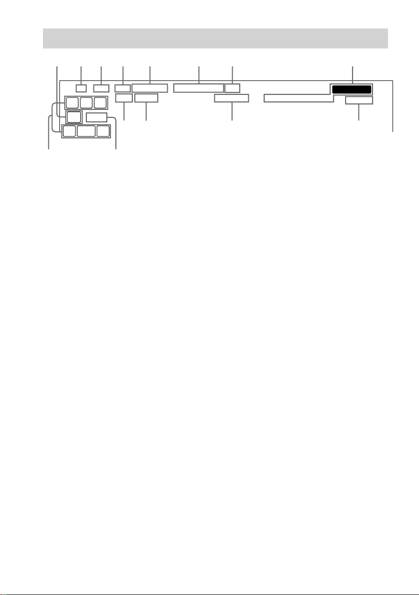
多重聲道環繞聲顯示說明
多重聲道環繞聲顯示說明
1234 5 6 7 8
aa
DIGITALSP BSP ASP PRO LOGIC II
LCR
SW
LFE
SL SR
S
qdqf
1 SW:當重低音揚聲器選項被設定于“YES”
(第 17 頁),而聲頻信號從 SUB WOOFER
插孔輸出時將亮起。
2 SP*:(STR-DE495 型號為限)當您開啟接
收機時將亮起。
3 SP A*:(STR-DE595 型號為限)當您選擇
驅動揚聲器系統 A 時將亮起。
4 SP B*:(STR-DE595 型號為限)當您選擇
驅動揚聲器系統 B 時將亮起。
* 當您連接頭戴耳機到 PHONES(耳機)插孔
時將並不亮起。
5 ; DIGITAL: 接收機給用杜比數字格式錄
音的信號解碼時將亮起。
6 ; PRO LOGIC II: 當接收機運用專業邏輯
處理于 2 聲道信號來輸出中央和環繞聲道
信號時“; PRO LOGIC”將亮起。當運用
專業邏輯 II 來處理(“PLII MOV”或
“PLII MUS”)時“; PRO LOGIC II”
將亮起(第 24 頁)。然而,如果把中央
和環繞聲揚聲器設定於“NO”並選擇
“A.F.D. AUTO”或“DOLBY PL”,這兩個
指示燈將不亮起。
註
杜比專業邏輯和杜比專業邏輯 II 的解碼對
于 DTS 格式的信號不起作用。
DTS
STEREOD.RANGECOAXOPT MONO RDS
MEMORY
SLEEP
90qaqs
7 DTS:當輸入 DTS 信號時將亮起。
註
播放 DTS 格式的光碟時,請確認已作好數字
連接,並確保 INPUT MODE 不被設定于
ANALOG(模擬)(第 21 頁)。
8 調諧器指示燈:當用接收機調諧廣播電台
等時將亮起。關于調諧器的操作,請參看
第 29-33 頁。
註
“RDS”只在地區碼為 CEL,CEK 的型號出
現。
9 SLEEP(睡眠): 當激活了睡眠定時器時,
點亮。
q; D.RANGE:啟動動態範圍壓縮功能時將亮
起。請參看第 27 頁關于調整動態範圍壓縮
的說明。
qa COAX: 當聲源信號是通過 COAXIAL 端子輸
入的數字信號時將亮起。
qs OPT: 當聲源信號是通過 OPTICAL 端子輸入
的數字信號時將亮起。
26
CS
Page 74
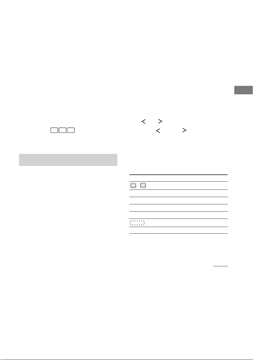
qd LFE:當播放含有 LFE(低頻效果)聲道的
光碟,以及當 LFE 聲道信號的聲音實際上
正在重新處理時將亮起。
qf 播放聲道指示燈:L,C,R 等文字表示播
放聲道。圍繞著文字的框格表示接收機用
于進行下降混頻信號源聲音的方式(依據
揚聲器設定)。當使用諸如“C.ST.EX”的
聲場時,接收機將根據信號源聲加入交混
回響效果。
L(前左),R(前右),C(中央(單聲
道)),SL(環繞聲左),SR(環繞聲
右),S(環繞聲(單聲道或由專業邏輯處
理獲得的環繞聲成分))。
舉例:
錄音格式(前∕環繞聲):3/2
輸出聲道:沒有啟動環繞聲揚聲器
聲場:A.F.D. AUTO
C R
L
SL SR
定製聲場
通過調整環繞聲參數和前揚聲器的音調特
性,您可定製聲場以迎合您的特殊聽賞喜
好。
一旦定製了聲場,它將一直存儲于指定的存
儲器中。然而,您只須重新調整參數,便可
隨時改變定製聲場。
關于各聲場中備有的參數,請參看封底的桌
表。
為獲得最佳的多重聲道環繞聲效果
要定製聲場之前,請按照從第 15 頁起的
“多重聲道環繞聲的設置”所說明的方法安
置好揚聲器,並作好各項調定工作。
調整電平參數
LEVEL 選單含有用于調整各揚聲器的平衡和
音量的參數。您也可以定制當前聲場多方面
的概況。此設定適用于所有的聲場除了
EFCT. 參數以外。至于 EFCT. 參數﹐此設
定將為每個聲場單獨儲存。
1 開始播放用多重聲道環繞聲編碼的節目信
號源。
2 反複按 MAIN MENU(主選單)以選擇
“ LEVEL ”。
3 按 MENU 或 MENU 以選擇所要調整
的參數。
4 按 MENU + 或 MENU - 以選擇所要的設
定。
設定即自動地被輸入。
初始設定
參數 初始設定
L
R BAL. L/R XX* BALANCE
CTR XXX dB* 0 dB
SUR.L. XXX dB* 0 dB
SUR.R. XXX dB* 0 dB
S.W. XXX dB* 0 dB
COMP. XXX OFF
D. RANGE
EFCT. XXX STD
享受環繞聲
* (STR-DE595 型號為限) MULTI CH IN 的參數可
各別地被調整。
接下頁
27
CS
Page 75
定製聲場(續)
前平衡 (L R BAL. L/R XX)
用于調整前左和前右揚聲器間的平衡。
中央電平 (CTR XXX dB)
用于調整中央揚聲器的電平。
環繞聲左電平 (SUR.L. XXX dB)
用于調整環繞聲左揚聲器的電平。
環繞聲右電平 (SUR.R. XXX dB)
用于調整環繞聲右揚聲器的電平。
重低音揚聲器電平 (S.W. XXX dB)
用于調整重低音揚聲器的電平。
動態範圍壓縮 (
用于壓縮聲跡的動態範圍。這項功能在深夜
裡用小音量觀賞電影片時很有用。我們建議
您選用“MAX”設定。
• 要再現無壓縮的聲跡時,請選擇“OFF”。
• 要再現錄影技師指定動態範圍的聲跡時,請
選擇“STD”。
• 要再現動態範圍極為顯著的壓縮效果時,請
選擇“MAX”。
註
動態範圍壓縮僅適用于杜比數字信號源。
效果電平 (EFCT. XXX)
用于調整當前環繞聲效果的“存在感”。
D. RANGE
COMP. XXX)
調整音調參數
TONE(音調)選單含有可讓您調整前揚聲器
的音調以獲取最理想的音響參數。此設定適
用于所有的聲場。
1 開始播放用多重聲道環繞聲編碼的節目信
號源。
2 反複按 MAIN MENU(主選單)以選擇
“ TONE ”。
3 按 MENU 或 MENU 以選擇所要調整
的參數。
4 按 MENU + 或 MENU - 以選擇所要的設
定。
設定即自動地被輸入。
初始設定
參數 初始設定
BASS XX dB 0 dB
TREB. XX dB 0 dB
低音 (BASS XX dB)
可讓您調整低音。
高音 (TREB. XX dB)
可讓您調整高音。
將定製聲場重調回工廠設定
1 如果接通著電源,請按 ?/1 以關掉電源。
2 按住 2CH,並按 ?/1 。
“SF. CLR.”即出現于顯示器,所有的
聲場則重調回工廠設定。
28
CS
Page 76
接收廣播
在接收廣播電台以前,務必將 FM 和 AM 天
線連接至接收機(第 7 頁)。
自動存儲 FM 電台
(AUTOBETICAL)
(地區碼 CEL,CEK 的型號為限)
此功能可不反複地按照字母順序存儲高達
30 個 FM 和 FM RDS 電台。此外,它僅存
儲信號最清晰的電台。
如果要逐一地存儲 FM 或 AM 電台,請參看
第 31 頁的“預約廣播電台”。
1 按 ?/1 以關掉接收機。
2 按住 MEMORY 並按 ?/1 以再次接通接收
機。
顯示器即出現“AUTO-BETICAL SELECT”
而接收機即開始掃描並存儲廣播地區的
所有 FM 和 FM RDS 電台。
對于 RDS 電台,調諧器將首先檢查廣播
同一節目的電台,然后僅存儲信號最清
晰的電台。所選 RDS 電台即按照它們的
節目服務名按字母分類,然后指配兩個
字符的預約碼。有關 RDS 詳情,請參看
第 32 頁。
一般的 FM 電台都有兩個字符的指配預
約碼,並被儲存在 RDS 電台之后。
完成設置后,“FINISH”即出現于顯示
器片刻,而接收機則恢復正常操作。
註
• 在 autobetical 操作中,請勿按接收機或附帶
遙控器上的任何按鈕。
• 如果您遷移到別的地區,請反複此程序以存儲
新地區的電台。
• 有關調諧存儲電台的詳情,請參看第 31 頁。
• 用此程序存儲電台之后,如果您移動天線位
置,所存儲的設定可能會無效。此時,您必須
反複此程序以再次存儲電台。
直接調諧
您可用附帶遙控器上的數字按鈕直接輸入所
要電台的頻率。關于本章節所使用的按鈕之
詳情,請參照第 37-40 頁。
1 反複按遙控器上的 TUNER 以選擇 FM 或
AM 波段。
最后接收的電台即被調入。
2 按遙控器上的 D.TUNING。
3 按數字按鈕以輸入頻率。
例 1: FM 102.50 MHz
bbbb
1 0 2 5 0
例 2: AM 1350 kHz
(當調諧度盤被設定為 10 kHz,您不必輸入最
后的“0”數字。)
bbb
1 3 5 0
如果您無法調入電台,並且輸入的數字閃
爍時
務必確認已輸入正確的頻率。否則,請
重複第 2 和 3 步驟。如果輸入的數字
仍舊閃爍,則表示該頻率不適用于您的
地區。
接收廣播
接下頁
29
CS
Page 77

直接調諧 (續)
自動調諧
4 如果您已調入 AM 電台,請調整 AM 環形天
線的方向以獲取最佳的接收。
5 反複步驟 1 到 4 以接收其他電台。
要領
• 如果忘記準確的頻率,您可在輸入所要電台的
近似頻率之后按 TUNING + 或 TUNING -。接收
機即自動地調入所要電台。如果頻率似乎比輸
入值高,請按 TUNING +,如果頻率似乎低于輸
入值,則按 TUNING -。
• 如果顯示器閃爍著“STEREO”,而 FM 立體聲
的接收狀況欠佳時,按 FM MODE 以更換為單聲
道 (MONO)。雖沒有立體聲效果,但聲音較不失
真。要返回立體聲模式時,再按一次 FM MODE。
如下表所示,調諧度盤將隨地區碼的不同而異。
有關地區碼的詳情,請參看第 4 頁。
地區碼 FM(調頻) AM(調幅)
U,CA 100 kHz(千赫)10 kHz(千赫)*
CEL,CEK, 50 kHz(千赫) 9 kHz(千赫)
SP,CN,TW,
KR,AU
E2/E3 50 kHz(千赫) 9 kHz(千赫)*
AR,MX 50 kHz(千赫) 10 kHz(千赫)
* AM 調諧度盤可以改變(第 45 頁)。
如果您不知道所要收聽電台的頻率,您可讓
接收機掃描當地所有的電台。
1 反複按 TUNER FM/AM 以選擇 FM 或 AM 波
段。
最后接收的電台即被調入。
2 按 TUNING + 或 TUNING -。
按 TUNING + 從低向高掃描;按 TUNING
- 從高向低掃描。
當接收到電台時,接收機即停止掃描。
當接收機掃描到波段的任何一端時
掃描將同方向地反複進行。
3 要持續掃描時,請再按一次 TUNING + 或
TUNING -。
預約調諧
用直接調諧或自動調諧調入電台之后,您可
以把它們預約到接收機裡。然后,您即可用
附帶的遙控器輸入兩個字符的預約碼直接調
入任何電台。高達 30 個 FM 或 AM 電台可
被預約。接收機也能掃描全部您所預約的電
台。
要調收預約電台以前,務必遵照本章節“預
約廣播電台”(第 31 頁)的步驟先行預
約。
30
CS
Page 78
預約廣播電台
1 按 TUNER FM/AM。
最后接收的電台即被調入。
2 用直接調諧(第 29 頁)或自動調諧(第
30 頁)調入所要預約的電台。
3 按 MEMORY。
“MEMORY”(存儲器)將顯示于顯示器
數秒。
請在“MEMORY”顯示熄滅以前進行步驟
4 到 5。
4 反複按 PRESET TUNING + 或 PRESET
TUNING - 以選擇預約的電台號碼。
每按一次此按鈕,預約的電台號碼將按
照如下順序和方向改變:
nA1˜A2˜...˜A0˜B1˜B2˜...˜B0N
nC0˜...C2˜C1N
在您選擇預約的電台號碼之前﹐如果
“MEMORY”(存儲器)顯示熄滅﹐請再
次從步驟 3 開始。
5 再按一次 MEMORY 以存儲電台。
在您儲存電台之前如果“MEMORY”顯示
熄滅,請再次從步驟 3 開始。
6 反複步驟 2 到 5 以預約其他電台。
調諧預約廣播電台
您可用下列兩種方式的其中之一調入預約電
台。
掃描預約廣播電台
1 按 TUNER FM/AM。
最后接收的電台即被調入。
2 反複按 PRESET TUNING + 或 PRESET
TUNING - 以選擇所要的預約電台。
每按一次此按鈕,接收機將按照如下順
序和方向一次調入一個預約電台。
nA1˜A2˜...˜A0˜B1˜B2˜...˜B0N
nC0˜...C2˜C1N
使用預約碼
使用附帶的遙控器執行下列操作。關于本章
節所使用的按鈕之詳情,請參照第 37-40
頁。
1 按遙控器上的 TUNER。
最后接收的電台即被調入。
2 按 SHIFT 以選擇存儲頁(A,B 或 C)。
然后用數字按鈕按所要電台的預約號。
接收廣播
要改變預約號至另一個電台時
請進行步驟 1 到 5 以預約一個新電台到該
預約號。
要領
在步驟 4﹐您也可以使用遙控器選擇預約的電台
號碼。反複按 SHIFT(轉移)以選擇存儲頁面
(A﹐B 或 C)﹐然后按數字鍵以選擇預約號。
31
CS
Page 79

使用無線電廣播數據系
統(RDS)
(地區碼 CEL,CEK 的型號為限)
本接收機也可讓您接收 RDS(無線電廣播數
據系統)。此系統可讓無線電廣播電台在一
般節目信號中播送附加信息。
請注意,RDS 只適用于 FM 電台。*
* 不是所有的 FM 電台都提供 RDS 服務,他們也
未必提供相同類型的服務。如果您不熟悉當地
的 RDS 服務,請諮詢當地無線電廣播電台以獲
取詳情。
接收 RDS 廣播
只需用直接調諧 (第 29 頁),自動調諧 (第
30 頁) 或預約調諧 (第 30 頁) 選擇一個 FM
波段的電台即可。
當您調入一個提供 RDS 服務的電台,RDS
指示燈將亮起。節目的電台名稱通常會出現
于顯示器。
註
如果所調收的電台沒有適當地傳輸 RDS 信號,或
如果信號強度太弱,RDS 功能便可能不起適當的
作用。
顯示 RDS 信息
正在接收 RDS 電台時按 DISPLAY。
每按一次此按鈕,顯示器上的 RDS 信息即
如下循環改變:
節目電台名 t 頻率 t 節目類型指示燈
t 無線電廣播文本指示燈b) t 當前時間指
示燈 (24 小時制) t 當前所用聲場
a) 廣播的節目類型(第 33 頁)。
b) 由 RDS 電台播送的文本訊息。
註
• 如果有緊急的政府通告,“ALARM”將閃爍于顯
示器。
• 如果此信息有 9 個或更多的字母,此信息將在
顯示器中滾動顯示。
• 如果電台不提供特殊的 RDS 服務,“NO
XXXX”(例如,“NO TEXT”)即出現于顯示
器。
a)
32
CS
Page 80
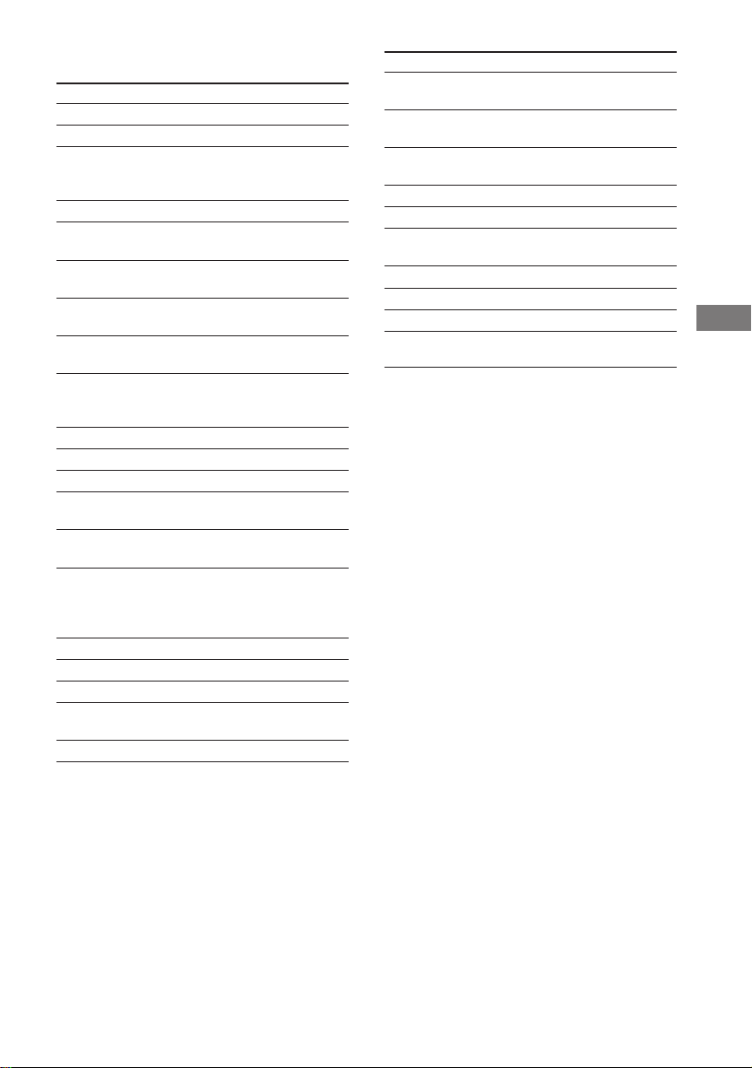
節目類型的說明
節目類型指示 說明
NEWS 新聞節目
AFFAIRS 時事焦點課題性節目
INFO 提供消費事務,
醫療保健等廣大領域
的節目
SPORT 體育節目
EDUCATE 教育性節目,例如
啟發性和引導性節目
DRAMA 無線電廣播戲劇和連
續劇
CULTURE 語言,社會等有關國
家或地區文化的節目
SCIENCE 有關自然科學和技術
的節目
VARIED 其他類型的節目,例如
名人採訪,解說團和
笑劇
POP M 流行音樂節目
ROCK M 搖滾音樂節目
EASY M 輕鬆聆聽節目
LIGHT M 演奏、歌唱和合唱
音樂
CLASSICS 名管絃樂團演奏的
室內樂、歌劇音樂等
OTHER M 不屬于以上任何類別的
音樂,例如 Rhythm
& Blues (節奏藍調)
和 Reggae (雷鬼音樂)
WEATHER 天氣預報
FINANCE 股票市場報告和貿易等
CHILDREN 兒童節目
SOCIAL 有關民生問題的社會
雜談
RELIGION 宗教內容的節目
節目類型指示 說明
PHONE IN 公眾用電話或在公眾討
論會上發表意見的節目
TRAVEL 有關旅遊的節目。不是
用于 TP/TA 找的報導
LEISURE 園藝、釣魚、烹飪
等休閑性節目
JAZZ 爵士音樂節目
COUNTRY 鄉村音樂節目
NATION M 國家或地區的流行音樂
節目
OLDIES 老歌節目
FOLK M 民謠節目
DOCUMENT 調查研究性質的節目
NONE 不屬于以上任何一項的
節目
接收廣播
33
CS
Page 81
其他操作
為預約電台和節目信號
源定名
每個預約電台或節目信號源可用高達 8 個
字符的名字(索引名稱)。每當選擇了電台
或節目信號源,這些名字(例如“VHS”)將
顯示于接收機的顯示器。請注意,您只能給
每個預約電台或節目信號源輸入一個名字。
此功能可用于識別同類型的單片機。例如兩
台錄影機可以分別被指定為“VHS”和
“8MM”。它也便于識別連接于已被指定為
其他類型單片機插頭的單片機。例如連接第
二台 CD 唱機到 MD/TAPE 插孔。
1 給預約電台定名
按 TUNER FM/AM,然后調收您要建立索引
名稱的預約電台。
如果仍不熟悉預約電台的調諧方法,可
參看第 30 頁的“調諧預約廣播電
台”。
給節目信號源定名
選擇要定名的節目信號源(單片機)。
2 反複按 MAIN MENU(主選單)以選擇
“ NAME ”。
3 使用 MENU + 或 MENU - 和 MENU 或
MENU 建立索引名稱:
請按 MENU + 或 MENU - 以選擇字符,
然后按 MENU 以移動游標到下一個位
置。
要插入空間時
請按 MENU + 或 MENU - 直至空白空間
出現于顯示器。
如果您輸入錯誤
反複按 MENU 或 MENU 直至要改
變的字符閃爍,然后按 MENU + 或 MENU
- 以選擇您想要的字符。
4 按 ENTER。
5 反複步驟 2 到 4 以指配其他電台或節目
信號源的索引名稱。
註
(地區碼 CEL,CEK 的型號為限)
您不能改變 RDS 電台的名字。
錄音∕影
開始操作之前,務必確認是否已妥當連接所
有的單片機。
錄在錄音帶或迷你光碟 (MD) 上
您可用此接收機在卡帶或迷你光碟上進行錄
制。必要時,可參看卡帶座或迷你光碟
(MD) 卡座的使用說明書。
1 選擇要進行錄制的單片機。
2 準備播放用的單片機。
例如將 CD 置入 CD 唱機內。
3 把空白磁帶或迷你光碟裝入錄音座,必要
時,請調整錄音電平。
4 開始錄音座的錄音,然后啟動播放用單片
機。
註
• 調節聲音不會影響從 MD/TAPE OUT 插孔輸出的
信號。
• (STR-DE595 型號為限) 當選取 MULTI CH IN,
當前輸入聲源的模擬聲頻信號將從 REC OUT 插
孔輸出。
• 有些聲源含有拷貝防擭以防翻錄。遇此情形
時,您可能無法從該聲源錄制。
34
CS
Page 82
錄在錄像帶上
您可用本接收機從錄影機,電視機或 DVD
播放機錄影。在編輯錄像帶時,您也可從各
種聲頻信號源加進聲頻。必要時,可參看錄
影機的使用說明書。
1 選擇要進行錄制的節目信號源。
2 準備播放用單片機。
例如裝入要錄到 DVD 播放機的 DVD。
3 把空白錄像帶裝入錄影用錄影機 (VIDEO
1)。
4 讓錄影機開始錄音,然后播放要錄的錄影
帶或 DVD。
要領
在拷貝錄影帶或 DVD 時,您可以把任何聲頻信號
源的聲音錄進錄像帶中。查找要從別的聲頻信號
源開始錄音的錄制起點,選擇節目信號源,然后
開始播放。來自該信號源的聲頻即被錄進錄像帶
的聲跡裡替代來自原來媒介的聲頻。要恢復從原
來媒體的錄音時,請再選一次視頻信號源。
註
• 請確定已將數字和模擬連接到 VIDEO 2 和 DVD
輸入插孔。如果只有數字連接,模擬錄制將無
法工作。
• (STR-DE595 型號為限) 當選取 MULTI CH IN,
當前輸入聲源的模擬聲頻信號將從 REC OUT 插
孔輸出。
使用睡眠定時器
您可設定接收機在指定的時間自動關閉。
在電源打開時按遙控器上的 SLEEP。
每按一次按鈕,顯示即如下循環切換:
2-00-00 t 1-30-00 t 1-00-00
t 0-30-00 t OFF(關掉)
要領
要在接收機關閉之前查看剩餘時間時,請按
SLEEP。剩餘時間即出現于顯示器。
用 SET UP 選單進行調整
SET UP 選單可讓您進行下列調整。
1 反複按 MAIN MENU(主選單)以選擇
“ SET UP ”。
2 按 MENU 或 MENU 以選擇所要調整
的參數。
3 按 MENU + 或 MENU - 以選擇所要的設定。
設定即自動地被輸入。
初始設定
參數 初始設定
DEC. XXXX PCM (供 DVD,
CD/SACD (STR-DE595
型號為限)),
AUTO (供 VIDEO 2)
其他操作
接下頁
35
CS
Page 83

用 SET UP 選單進行調整 (續)
x 優先解碼 (DEC. XXXX)
為輸入的數字信號設定適當的解碼。
• PCM 優先模式 (DEC. PCM)
使用它以享受于來自聲頻 CD (PCM) 和
DVD 的播放。當 CD 或 DVD 以外的媒介
使用時,您可能會感受到噪音。若此事發
生,轉換至 AUTO (自動) 模式。
• AUTO (自動)模式 (DEC. AUTO)
使用它以享受于來自聲頻 CD (PCM),
DVD, DTS-CD 和 DTS-LD 聲源的播放。
但是,使用聲頻 CDs,您可能無法聆聽每
個音軌的最初時刻。
通常,使用上述的初始設定。
改變接收機的指令模式
當您在同一房間里使用兩台 Sony 接收機
時﹐此功能非常有用。
1 關掉接收機。
2 按住 ENTER 並按 ?/1 以關掉接收機。
“C.MODE.AVX”出現在顯示器中。
每次您反複上述程序﹐顯示器將按照如
下改變:
C.MODE.AV1 y C.MODE.AV2
要領
初始設定為“C.MODE.AV2”。
註
• 附帶遙控器指令模式為“AV2”並且您將無法改
變此設定。
• 若接收機與遙控器的指令模式不同,您將無法
用遙控器來操作接收機。
36
CS
Page 84
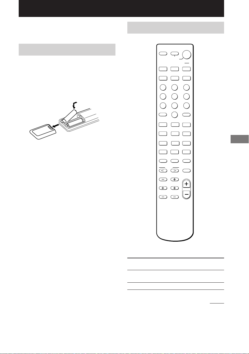
用 RM-U306A 遙控器操作
您可用 RM-U306A 遙控器操作您系統的單片
機。
在使用您的遙控器之前
把電池裝入遙控器
在電池室中裝入 R6(AA 號)乾電池並對準
+ 和 - 電極。使用遙控器時,必須瞄準接
收機上的遙控傳感器 g。
]
}
}
]
要領
在一般使用狀況下,電池可耐用大約 6 個月。當
遙控器不能再操作接收機時,請換上兩節新的電
池。
註
• 不要把遙控器放置在太熱或太潮濕的地方。
• 不要混用新、舊電池。
• 別讓遙控傳感器受陽光或電燈的強光直射。否
則,可能引起故障。
• 如果準備長時期不用遙控器,請取出電池以免
因電池漏液及腐蝕而損壞遙控器。
遙控器按鈕說明
AV
SLEEP
?/1
SYSTEM
STANDBY
VIDEO 1
VIDEO 2
MD/TAPE CD TUNER
TOP MENU DVD MENU
SHIFT
>10
.
m
TEST TONE MAIN MENU MULTI CH
TV VOL TV CH
F
123
G
ENTER
456
f
7809
-
–
CH/PRESET
N
2CH A.F.D.
MENU
>
M
D.TUNING
ENTER
RETURN
+
TV/VIDEO
TV/VTR
D.SKIP
X
MOVIE/
MUSIC
MUTING
MASTER
VOL
?/1
DVD
ANT
x
g
O
用 RM-U306A 遙控器操作
下列桌表說明各按鈕的功能。
遙控器 操作 功能
按鈕
SLEEP 接收機 啟動睡眠功能和接收機
自動關閉的時限。
?/1 接收機 打開或關閉接收機。
接下頁
37
CS
Page 85

遙控器按鈕說明 (續)
遙控器 操作 功能
按鈕
VIDEO 1 接收機 觀看錄影機。
(VTR 模式 3)
VIDEO 2 接收機 觀看錄影機。
(VTR 模式 1)
DVD 接收機 觀看 DVD。
MD/TAPE 接收機 聆聽 MD 或錄音帶。
CD 接收機 聆聽 CD。
TUNER 接收機 收聽廣播電台。
SHIFT 接收機 反複按下以選擇預約電
台或調入預約的電台所
用的存儲頁。
D.TUNING 接收機 調諧器電台直接輸入模
式。
2CH 接收機 選擇 2CH 模式。
A.F.D. 接收機 選擇 A.F.D. AUTO,
DOLBY PL,PLII MOV
和 PLII MUS。
MOVIE/ 接收機 選擇 C.ST.EX A,
MUSIC C.ST.EX B,C.ST.EX
C,HALL,JAZZ 和
CONCERT。
TEST 接收機 按下以輸出測試音。
TONE
MAIN 接收機 反複按此按鈕以選擇四
MENU 種游標模式的其中
之一:SET UP,
LEVEL,TONE 和
NAME。
MULTI CH 接收機 選擇 MULTI CH IN 信
號源。
MENU I/i 接收機 選取選單項目。
MENU +/– 接收機 進行調整或改變設定。
MUTING 接收機 消除來自接收機的聲
音。
遙控器 操作 功能
按鈕
MASTER 接收機 調整接收機的主音
VOL +/– 量。
AV ?/1 電視機∕ 打開或關閉聲視頻單
錄影機∕ 片機。
CD 唱機∕
VCD 播放機∕
鐳射影碟
播放機∕
DVD 播放機∕
MD 卡座∕
DAT 卡座
SYSTEM 接收機/ 關閉接收機和其他
STANDBY 電視機∕ Sony 聲頻/視頻單片
(同時按 錄影機∕ 機。
AV ?/1 衛星調諧器∕
和 ?/1) CD 唱機∕
VCD 播放機∕
鐳射影碟
播放機∕
DVD 播放機∕
MD 卡座∕
DAT 卡座
0-9 接收機 與“SHIFT”按鈕配
合 使用以預約電台
或調入預約的電台並
與“D.TUNING”配合
以直接調諧。
CD 唱機∕ 選擇曲號。
VCD 播放機∕ 0 選擇曲號 10。
鐳射影碟
播放機∕
MD 卡座∕
DAT 卡座
電視機∕ 選擇頻道號。
錄影機∕
衛星調諧器
>10 CD 唱機∕ 選擇超過 10 的曲
VCD 播放機∕ 號。
鐳射影碟
播放機∕
MD 卡座∕
磁帶卡座
38
CS
Page 86
遙控器 操作 功能
按鈕
ENTER 電視機∕ 用數字按鈕選取頻道、
RETURN VCD 播放機 回到之前的選單。
CH/
PRESET
+/–
./> 錄影機/ 跳越曲子。
m/M CD 唱機/ 尋找曲子
N 錄影機∕ 開始播放。
錄影機∕ 光碟或聲軌之后,按下
衛星調諧器∕ 以輸入數值。
鐳射影碟
播放機∕
MD 卡座∕
DAT 卡座∕
磁帶卡座
接收機 掃描和選擇預約電台。
電視機∕ 選擇預約頻道。
錄影機∕
衛星接收機
CD 唱機∕
VCD 播放機/
鐳射影碟
播放機∕
DVD 播放機∕
MD 卡座∕
DAT 卡座∕
磁帶卡座
VCD 播放機∕
DVD 播放機
錄影機∕ 快進或重繞。
鐳射影碟
播放機∕
MD 卡座∕
DAT 卡座∕
磁帶卡座
CD 唱機/
VCD 播放機∕
鐳射影碟
播放機∕
DVD 播放機/
MD 卡座∕
DAT 卡座/
磁帶卡座
(向前或向后)。
遙控器 操作 功能
按鈕
X 錄影機∕ 暫停播放或錄。
x 錄影機∕ 停止播放。
ANT 錄影機 選擇來自天線端子的
TV/VTR 輸出信號:電視信號
D.SKIP
TOP DVD 播放機 顯示 DVD 標題。
MENU
DVD DVD 播放機 顯示 DVD 選單。
MENU
ENTER DVD 播放機 輸入選單。
O DVD 播放機 返回之前的選單或退
V/v/B/b DVD 播放機 選擇選單項目。
CD 唱機/ 音∕影(單片機呈錄
VCD 播放機∕ 音∕影備用模式時,
鐳射影碟
播放機∕
DVD 播放機/
MD 卡座∕
DAT 卡座/
磁帶卡座
CD 唱機∕
VCD 播放機∕
鐳射影碟
播放機∕
DVD 播放機∕
MD 卡座∕
DAT 卡座/
磁帶卡座
CD 唱機/ 跳越光碟(僅于多用
VCD 播放機/ 途光碟轉換器)。
DVD 播放機/
MD 卡座
則開始錄音∕影。)
或錄影機節目。
出選單。
接下頁
用 RM-U306A 遙控器操作
39
CS
Page 87

遙控器按鈕說明 (續)
遙控器 操作 功能
按鈕
-/-- 電視機 選擇頻道輸入模式,
TV/VIDEO
TV VOL 電視機 調整電視機的音量。
+/–
TV CH 電視機 選擇預約頻道。
+/–
註
• 當您按下輸入選擇器按鈕 (VIDEO 1,VIDEO
2,DVD),電視機的輸入模式可能無法轉換至您
所要之相應的輸入模式。在此情況下,按 TV/
VIDEO 按鈕以轉換電視機的輸入模式。
• 視接收機的型號而定,在本章節裡所提及的某
些功能可能無效。
• 以上說明僅作為範例。
因此,依據單片機而定,以上的操作可能無
效,或者其操作可能與說明有所出入。
• (STR-DE495 型號為限) MULTI CH 功能對設置
操作不起作用 。
電視機 選擇輸入信號:電視
一位或兩位數。
輸入或視頻輸入。
改變輸入選擇器按鈕的出
廠預設
如果輸入選擇器按鈕的出廠預設不符合您系
統的單片機,您可將它更換。例如若您有磁
帶卡座而沒有 MD 卡座時,您可按磁帶卡座
的 MD/TAPE 按鈕。
請注意,TUNER 按鈕的設定是不能更改的。
1 按住您想要更改輸入聲源的輸入選擇器按鈕
(例如 MD/TAPE)。
2 按單片機的相應按鈕;您要指配的輸入選
擇器按鈕(例如 4 - 磁帶卡座)。
下列按鈕用以選擇各別的輸入聲源:
要操作 請按下
CD 唱機 1
DAT 卡座 2
MD 卡座 3
磁帶卡座 A 4
磁帶卡座 B 5
鐳射影碟播放機 6
錄影機(指令模式 VTR 1*) 7
錄影機(指令模式 VTR 2*) 8
錄影機(指令模式 VTR 3*) 9
電視機 0
DSS(數字衛星接收機) >10
DVD 播放機 ENTER
VCD 播放機 .
* Sony 錄影機可用 VTR 1,2 或 3 的設定操
作。這些設置分別適用于 Beta,8mm 和
VHS。
現在,您可用 MD/TAPE 按鈕操作磁帶卡
座。
要將按鈕重設回出廠預設時
請重複上述步驟。
要將所有的輸入選擇器按鈕都重設回出廠預設
時
同時按 ?/1,AV ?/1 和 MASTER VOL - 。
40
CS
Page 88

附加信息
使用前注意事項
安全須知
萬一有雜物或液體掉進機殼內,請立即拔下接收
機插頭並找合格人員檢查過后才可以再操作使
用。
電源須知
• 操作本機之前,請先檢查操作電壓是否符合當
地的電源電壓。接收機的操作電壓標示在接收
機背后的銘板上。
• 雖然已關閉接收機的電源,如果沒有從牆上插
座拔出電線,本機並未完全與 AC 電源(主電
源)隔離。
• 如果長時間不使用接收機,請從牆上插座拔下
接收機的電源線。要拔下 AC 電源線時,必須
抓住插頭拔出,不可拉著導線拔。
• (地區碼 U,CA 的型號為限)
為了安全的起見,插頭的一個刃片比其他的寬
並以一種方式插入到牆上插座中,如果您無法
將此插頭完全插入到插座中,請聯絡您的銷售
商。
• AC 電源線僅可在授權的維修中心更換。
內積熱須知
在操作時本機會加熱,這並非故障。如果持續使
用本機,機殼頂部,側面和底面的溫度會上升得
相當高。為免被燙傷,請不要接觸機殼。
安置須知
• 必須安裝接收機于通風良好的地方以防積熱,
並延長接收機的使用壽命。
• 不要把接收機放在靠近熱源或陽光直射,多塵
或有機械性衝擊的地方。
• 別在機殼頂上放置任何東西以免堵住通風孔而
引起故障。
• 當放置此機到經過特別處理的表面(帶有蜡﹐
油﹐擦亮劑﹐等)時請小心使用﹐否則可能造
成表面被沾污或變色。
操作須知
要連接別的單片機之前,請先關掉接收機的電
源,並拔下電源插頭。
清潔須知
請用溫和的洗滌劑清洗機殼,控制板和控制器。
不可使用任何類型的砂布,磨粉或酒精,苯等溶
劑。
故障探尋
使用接收機時如果碰到如下困難,請用此故
障探尋指南試著解決問題,並參看第 20 頁
的“檢查連接”以確認連接是否正確。如果
仍不能解決問題,請洽詢附近的 Sony 經銷
商。
無論選那個單片機都無聲音或只聽到極小的聲音。
• 檢查揚聲器和單片機的連接是否正確及穩
固。
• 檢查接收機和所有的單片機是否都已打開了
電源。
• 檢查 MASTER VOLUME 控制按鈕沒有被設定在
“VOL MIN”。
• 按遙控器上的 MUTING 以解除靜音功能。
• (STR-DE595 型號為限) 檢查 SPEAKERS
(OFF/A/B/A+B) 按鈕並未設定為關﹐並且依
據您的 SPEAKERS FRONT (前揚聲器) 系統而
設定 (第 22 頁)。
• 確認未連接頭戴耳機。
• 因發生短路而啟動了接收機的保護裝置
(“PROTECT”將閃爍)。請關掉接收機電源,
解決了短路問題之后再打開電源。
接下頁
附加信息
如果您對接收機仍有任何疑問或問題,請洽詢附
近的 Sony 經銷商。
41
CS
Page 89

故障探尋(續)
指定的單片機沒有發出聲音。
• 確認單片機是正確地連接在該單片機所用的
聲頻輸入插孔。
• 確認連接用導線已妥當地接插于接收機和單
片機的插孔。
• 檢查是否選對了接收機上的單片機。
其中一個前揚聲器沒有聲音。
連接一對頭戴耳機至 PHONES 插孔以確認聲音
是否自頭戴耳機輸出(第 22 頁)。
如果只有一個聲道從頭戴耳機輸出,單片機可
能沒有被正確地連接至接收機。請查看所有的
導線是否都已妥善地插入接收機和單片機。
如果兩個聲道都從頭戴耳機輸出,前揚聲器可
能沒有被正確地連接至接收機。請查看完全沒
有輸出聲音的前揚聲器。
左和右聲音不平衡或相反。
• 檢查揚聲器和單片機的連接是否正確及穩
固。
• 調整 LEVEL 選單的平衡參數。
有嚴重的哼聲或噪音。
• 檢查揚聲器和單片機的連接是否正確及穩
固。
• 檢查連接導線是否遠離變壓器或電動機,並
且至少離開電視機或熒光燈 3 米。
• 把電視機移離聲頻單片機。
• 插頭和插孔都髒了。請用微蘸酒精的布擦
拭。
從中央或∕和環繞聲揚聲器上聽不到聲音或只聽見極
小的聲音。
• 確認是否已打開了聲場功能(按 MOVIE 或
MUSIC)。
• 選擇含有“C.ST.EX”字樣的聲場(第 24
頁)。
• 調整揚聲器的電平(第 20 頁)。
• 確認中央或∕和環繞聲揚聲器的尺寸參數是
否設定于“SMALL”或“LARGE”(第 17
頁)。
有源重低音揚聲器沒有輸出聲音。
• 檢查重低音揚聲器的連接是否正確及穩固。
• 請確定重低音揚聲器的選項已被設定為
“YES”(第 17 頁)。
• 視聲場所定,可能沒有聲音自 SUB WOOFER
端子輸出(封底)。
無法獲得環繞聲效果。
確認是否已打開了聲場功能(按 MOVIE 或
MUSIC)。
不能再現杜比數字(Dolby Digital)或 DTS 多重聲
道音響。
• 檢查播放中的 DVD 等是否用杜比數字或 DTS
格式錄制。
• 當連接 DVD 播放機等到此接收機的數字輸入
插孔,請檢查所連接單片機的聲頻設定(聲
頻輸出用的設定)。
不能錄音。
• 檢查單片機的連接是否正確。
• 用輸入選擇器選擇音源單片機。
• 開始從連接到模擬 MD/TAPE 端子的數字單片
機錄音之前,請確定 INPUT MODE 已被設定
為 “ANALOG”(第 21 頁)。
42
CS
Page 90
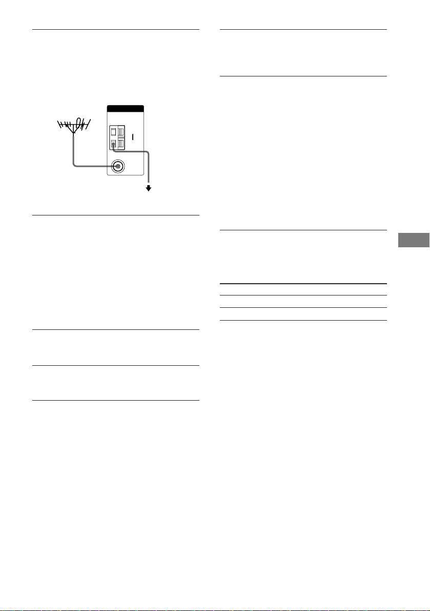
FM 接收狀況欠差。
如下圖所示用 75 歐的同軸電纜(無附帶)將
接收機連接至室外 FM 天線。如果將接收機連接
至室外天線,請把它接地以防閃電。為防止煤
氣爆炸事故,請勿將地線連接至煤氣配管。
接收機
室外 FM 天線
ANTENNA
COAXIAL
AM
y
FM
75Ω
接地線
(無附帶)
接地
不能調入電台。
• 檢查是否已穩固地連接天線。
請調整天線。必要時,請連接室外天線。
• 電台的信號強度太弱(當用自動調諧調入
時)。請改用直接調諧。
• 確認調諧間隔是否設定正確(當用直接調諧
調入 AM 電台時)。
• 未曾預約電台或預約電台已被清除(用掃描
預約電台調諧時)。請預約電台(第 31
頁)。
• 按 DISPLAY 使頻率出現于顯示器。
RDS 不起作用。*
• 確認是否已調入 FM RDS 電台。
• 選擇信號較強的 FM 電台。
未出現所要的 RDS 信息。*
詢問廣播電台是否提供上述服務。如果有,那
可能是該項服務只是暫時不正常而已。
電視屏幕或監視器上沒有影像或影像不清晰。
• 選擇接收機上適當的輸入選擇器。
• 把電視機設定于適當的輸入模式。
• 把電視機移離聲頻單片機。
遙控器不起作用。
• (STR-DE495 型號為限) 遙控器上的 MULTI
CH 按鈕將不起作用。
• 遙控器必須指向接收機的遙控傳感器 g。
• 檢查您是否已選擇 AV2 作為接收機的指令模
式(第 36 頁)。
• 排除遙控器和接收機通訊之間的任何障礙
物。
• 如果遙控器的電池變弱,請換上兩節新的電
池。
• 請確定遙控器上所選的輸入選擇器是否正
確。
• 如果遙控器被設定為只操作電視機,在操作
接收機或其他單片機之前,請用遙控器選擇
電視機以外的播放源或單片機。
* 地區碼 CEL,CEK 的型號為限。
清除接收機的存儲
要清除 請參看
所有存儲的設定 第 15 頁
定製聲場 第 28 頁
附加信息
43
CS
Page 91

規格
放大器部分
功率輸出
地區碼 U,CA 的型號
立體聲模式時的額定功率輸出
(8 歐 40 Hz - 20 kHz,總諧波失真 0.09 %)
STR-DE595: 90 W + 90 W
STR-DE495: 70 W + 70 W
基準功率輸出
(8 歐 40 Hz - 20 kHz,總諧波失真 0.09 %)
STR-DE595: FRONT1): 90 W/ch
STR-DE495: FRONT1): 70 W/ch
(8 歐 1 kHz,總諧波失真 0.7 %)
STR-DE595: FRONT1): 100 W/ch
STR-DE495: FRONT1): 80 W/ch
地區碼 CEL,CEK 的型號
立體聲模式時的額定功率輸出
(8 歐 1 kHz,總諧波失真 0.7 %)
STR-DE595: 100 W + 100 W
STR-DE495: 80 W + 80 W
基準功率輸出
2)
(8 歐 1 kHz,總諧波失真 0.7 %)
STR-DE595: FRONT1): 100 W/ch
STR-DE495: FRONT1): 80 W/ch
地區碼 SP 的型號
立體聲模式時的額定功率輸出
(8 歐 1 kHz,總諧波失真 0.7 %)
STR-DE595: 90 W + 90 W
STR-DE495: 70 W + 70 W
基準功率輸出
2)
(8 歐 1 kHz,總諧波失真 10 %)
STR-DE595: FRONT1): 110 W/ch
STR-DE495: FRONT1): 90 W/ch
CENTER1): 90 W
SURR1): 90 W/ch
CENTER1): 70 W
SURR1): 70 W/ch
CENTER1): 100 W
SURR1): 100 W/ch
CENTER1): 80 W
SURR1): 80 W/ch
2)
2)
CENTER1): 100 W
SURR1): 100 W/ch
CENTER1): 80 W
SURR1): 80 W/ch
2)
2)
CENTER1): 110 W
SURR1): 110 W/ch
CENTER1): 90 W
SURR1): 90 W/ch
地區碼 CN,KR 的型號
立體聲模式時的額定功率輸出
(8 歐 1 kHz,總諧波失真 0.7 %)
STR-DE595: 100 W + 100 W
90 W + 90 W
STR-DE495: 80 W + 80 W
基準功率輸出
(8 歐 1 kHz,總諧波失真 10 %)
2)
70 W + 70 W
2)
3)
2)
3)
STR-DE595: FRONT1): 120 W/ch
CENTER1): 120 W
SURR1): 120 W/ch
STR-DE495: FRONT1): 100 W/ch
CENTER1): 100 W
SURR1): 100 W/ch
其他地區碼的型號
立體聲模式時的額定功率輸出
(8 歐 1 kHz,總諧波失真 0.7 %)
STR-DE595: 100 W + 100 W
STR-DE495: 80 W + 80 W
基準功率輸出
(8 歐 1 kHz,總諧波失真 10 %)
2)
2)
2)
STR-DE595: FRONT1): 120 W/ch
CENTER1): 120 W
SURR1): 120 W/ch
STR-DE495: FRONT1): 100 W/ch
CENTER1): 100 W
SURR1): 100 W/ch
1) 視聲場設定和信號源而定,可能無聲音輸出。
2) 在下列條件下測定:
地區碼 電源
E2/E3 240 V AC,50 Hz
SP,CEL,CEK,AR, 230 V AC,50 Hz
CN,KR
TW 110 V AC,60 Hz
3) 在下列條件下測定:
地區碼 電源
CN,KR 220 V AC,50 Hz
頻率響應
MULTI CH IN
(STR-DE595 型號為
限),CD (STR-DE495
10 Hz – 50 kHz
+0.5/-2 dB (具有聲場
和音調旁通)
型號為限),MD/TAPE,
DVD,VIDEO 1,2
CD/SACD (STR-DE595
型號為限)
10 Hz – 70 kHz
+0.5/-2 dB (具有聲場
和音調旁通)
44
CS
Page 92
輸入 (模擬)
MULTI CH IN (STRDE595 型號為限),
CD/SACD (STR-DE595
型號為限),CD (STR-
靈敏度: 500 mV
阻抗: 50 千歐
信噪比4): 96 dB
(A,500 mV5))
DE495 型號為限),
MD/TAPE,DVD,
VIDEO 1,2
4)
INPUT SHORT(輸入短路) (具有聲場和音調旁
通)。
5) 權重網絡,輸入電平。
S/N(信噪比)
Mono(單聲道): 76 dB
Stereo(立體聲): 70 dB
1 kHz 時的諧波失真
Mono(單聲道): 0.3 %
Stereo(立體聲): 0.5 %
分離 1 kHz 時為 45 dB
頻率響應 30 Hz - 15 kHz,
+0.5/-2 dB
選擇性 400 kHz 時為 60 dB
輸入(數字)
DVD (同軸)
靈敏度: –
阻抗: 75 歐
信噪比: 100 dB
(A,20 kHz LPF)
CD/SACD (光頻)
(STR-DE595 型號為
限),VIDEO 2
(光頻)
靈敏度: –
阻抗: –
信噪比: 100 dB
(A,20 kHz LPF)
輸出
MD/TAPE (OUT),
VIDEO 1 (AUDIO
電壓: 500 mV
阻抗: 10 千歐
OUT)
SUB WOOFER
電壓: 2 V
阻抗: 1 千歐
音調
增益電平: ±6 dB,1 dB 步進
FM 調諧器部分
調諧範圍 87.5 - 108.0 MHz
天線端子 75 歐,不平衡
中頻 10.7 MHz
靈敏度
Mono(單聲道): 18.3 dBf,2.2 µV/75 歐
Stereo(立體聲): 38.3 dBf,
22.5 µV/75
有效靈敏度 11.2 dBf,1 µ V/75 歐
AM 調諧器部分
調諧範圍
地區碼 U,CA 的型號
用 10-kHz 調諧度盤: 530 - 1710 kHz
用 9-kHz 調諧度盤: 531 - 1710 kHz
地區碼 E2/E3 的型號
用 10-kHz 調諧度盤: 530 - 1610 kHz
用 9-kHz 調諧度盤: 531 - 1602 kHz
地區碼 CEL,CEK,SP,CN,TW,KR,AU 的型號
用 9-kHz 調諧度盤: 531 - 1602 kHz
地區碼 AR,MX 的型號
用 10-kHz 調諧度盤: 530 - 1610 kHz
天線 環形天線
中頻 450 kHz
有效靈敏度 50 dB/m (1,000 kHz 或
999 kHz 時)
S/N(信噪比) 54 dB (50 mV/m 時)
諧波失真 0.5 % (50 mV/m,
400 Hz)
選擇性
9 kHz 時: 35 dB
10 kHz 時: 40 dB
6) 您可將 AM 調諧度盤更換為 9 kHz 或 10 kHz。
在調入任何 AM 電台后關閉接收機,按住
PRESET TUNING + 並按 ?/1。當您更換調諧度
盤時,所有的預約電台會被抹消。要將度盤重
設回 10 kHz(或 9 kHz)時,請重複以上步
歐
驟。
6)
6)
6)
6)
接下頁
附加信息
45
CS
Page 93
規格(續)
視頻(錄影)部分
輸入
視頻: 1 Vp-p,75 歐
單片視頻(STR-DE595 型號為限,地區碼 CEL,
CEK 型號除外):
Y: 1 Vp-p,75 歐
PB/B-Y: 0.7 Vp-p,75 歐
PR/R-Y: 0.7 Vp-p,75 歐
輸出
視頻: 1 Vp-p,75 歐
單片視頻(STR-DE595 型號為限,地區碼 CEL,
CEK 型號除外):
Y: 1 Vp-p,75 歐
PB/B-Y: 0.7 Vp-p,75 歐
PR/R-Y: 0.7 Vp-p,75 歐
一般規格
電源
地區碼 電源
U,CA,MX 120 V AC,60 Hz
CEL,CEK 230 V AC,50/60 Hz
SP,AR,CN,KR 220 - 230 V AC,50/60 Hz
E2/E3 120/220/240 V AC,50/60 Hz
TW 110 V AC,50/60 Hz
AU 240 V AC,50 Hz
電力消耗
地區碼 電力消耗
U, MX STR-DE595: 210 W
CA STR-DE595: 310 VA
CEL,CEK,TW,KR STR-DE595: 210 W
SP STR-DE595: 180 W
CN STR-DE595: 205 W
AU,E2/E3,AR STR-DE595: 210 W
電力消耗(備用模式中)
0.3 W
尺寸 430 × 145 × 298 mm
質量(大約值)
STR-DE595: 7.5 kg
STR-DE495: 7.2 kg
附帶附件:
FM 電線天線 (1)
AM 環形天線 (1)
RM-U306A 遙控器 (1)
R6 (AA 號) 電池 (2)
有關您使用的組成機的地區碼詳情,請參看第
4 頁。
設計和規格有所變更時,恕不另行奉告。
STR-DE495: 250 VA
STR-DE495: 180 W
STR-DE495: 180 W
包含凸起部分和控制器
46
CS
Page 94
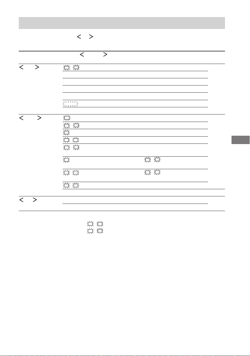
使用 MAIN MENU 按鈕的設定一覽表
您可用 MAIN MENU,MENU / 和 MENU +/– 按鈕進行各項設定。
以下桌表說明這些按鈕
可作的各項設置。
反複按 MAIN MENU 按 MENU 或 MENU 以選擇 按 MENU + 或 MENU – 以選擇 頁數
以選擇
LEVEL
SET UP
TONE BASS XX dB -6 dB 到 +6 dB (1 dB 步進) 28
1)
用于地區碼 U,CA 的型號:3 英尺到 23 英尺(1 英尺步進)
2)
用于地區碼 U,CA 的型號:在 L R DIST. 和 5 英尺之間 (1 英尺步進)
3)
用于地區碼 U,CA 的型號:在 L R DIST. 和 15 英尺之間 (1 英尺步進)
L
R BAL. L/R XX L +8 到 R +8 (1 步進) 27
CTR XXX dB -10 dB 到 +10 dB (1 dB 步進)
SUR.L. XXX dB -10 dB 到 +10 dB (1 dB 步進)
SUR.R. XXX dB -10 dB 到 +10 dB (1 dB 步進)
S.W. XXX dB -10 dB 到 +10 dB (1 dB 步進)
COMP. XXX OFF,STD,MAX
D. RANGE
EFCT. XXX 因聲場而異 (MIN,STD,MAX)
SW
(SUB WOOFER) S.W. XXX YES,NO 16
L
R (FRONT) XXXXX LARGE,SMALL
C
(CENTER) XXXXX LARGE,SMALL,NO
SL
SR (SURROUND) XXXXX LARGE,SMALL,NO
L
R DIST. X.X m (XX ft.) 在 1.0 米和 7.0 米之間
(0.1 米步進)
C
DIST. X.X m (XX ft.) 在 L R DIST. 和 1.5 米之間
(0.1 米步進)
SL
SR DIST. X.X m (XX ft.) 在 L R DIST. 和 4.5 米之間
(0.1 米步進)
SL
SR PL. XXXX LOW,HIGH
1)
2)
3)
DEC. XXXX AUTO,PCM 35
TREB. XX dB -6 dB 到 +6 dB (1 dB 步進)
附加信息
47
CS
Page 95
各聲場的可調整參數
所調整的 BASS 和 TREB. 參數適用于各聲場中。
< TONE >
BASS TREB.
2CH ST. zz
A.F.D. AUTO zz
DOLBY PL zz
PLII MOV zz
PLII MUS zz
C.ST.EX A zz
C.ST.EX B zz
C.ST.EX C zz
HALL zz
JAZZ zz
CONCERT zz
MULTI CH IN
PCM 96K
所調整的 LEVEL 參數適用于所有的聲場除了 EFCT. 參數以外。對于 EFCT. 參數﹐此設定為
每個聲場單獨儲存。
2CH ST. zz
A.F.D. AUTO zzzzzz
DOLBY PL zzzzzz
PLII MOV zzzzzz
PLII MUS zzzzzz
C.ST.EX A zzzzzzz
C.ST.EX B zzzzzzz
C.ST.EX C zzzzzzz
HALL zzzz z3)zz
JAZZ zzzz z3)zz
CONCERT zzzz z3)zz
MULTI CH IN
PCM 96K z
1)
STR-DE595 型號為限。
2)
視信號源或所作的調整而定,這些參數可能不起作用。請參看“調整電平參數”(第 27 頁)的各項目
以獲取詳情。
3)
當選取這些聲場,如果前揚聲器的尺寸被設定為“LARGE”,則重低音揚聲器將不會輸出聲音。但是,如
果數字輸入信號含有 LFE 信號,聲音即從重低音揚聲器輸出。
1)
< LEVEL >
FRONT CENTER SUR.L. SUR.R. S.W. D.RANGE EFCT.
BAL LEVEL LEVEL LEVEL LEVEL COMP
1)
zzzzz
2)
LEVEL
Sony Corporation Printed in China
CS
48
 Loading...