

Page 1

FM Ster eo
FM-AM Receiver
4-229-127-82(1)
Operating Instructions
Instrukcja obsługi
Инструкция по эксплуатации
GB
PL
RU
STR-DB940
STR-DB840
2000 Sony Corporation
Page 2

WARNING
Precautions
To prevent fire or shock
hazard, do not expose the
unit to rain or moisture.
To avoid electrical shock, do not
open the cabinet. Refer
servicing to qualified personnel
only.
Do not install the appliance in a
confined space, such as a
bookcase or built-in cabinet.
On safety
Should any solid object or liquid fall into
the cabinet, unplug the receiver and have it
checked by qualified personnel before
operating it any further.
On power sources
• Before operating the receiver, check that
the operating voltage is identical with
your local power supply. The operating
voltage is indicated on the nameplate at
the rear of the receiver.
• The unit is not disconnected from the AC
power source (mains) as long as it is
connected to the wall outlet, even if the
unit itself has been turned off.
• If you are not going to use the receiver
for a long time, be sure to disconnect the
receiver from the wall outlet. To
disconnect the AC power cord, grasp the
plug itself; never pull the cord.
• AC power cord must be changed only at
the qualified service shop.
On placement
• Place the receiver in a location with
adequate ventilation to prevent heat
buildup and prolong the life of the
receiver.
• Do not place the receiver near heat
sources, or in a place subject to direct
sunlight, excessive dust or mechanical
shock.
• Do not place anything on top of the
cabinet that might block the ventilation
holes and cause malfunctions.
On operation
Before connecting other components, be
sure to turn off and unplug the receiver.
On cleaning
Clean the cabinet, panel and controls with
a soft cloth slightly moistened with a mild
detergent solution. Do not use any type of
abrasive pad, scouring powder or solvent
such as alcohol or benzine.
If you have any question or problem
concerning your receiver, please
consult your nearest Sony dealer.
GB
2
Page 3
About This Manual
The instructions in this manual are for models
STR-DB940 and STR-DB840. Check your model number
by looking at the lower right corner of the front panel. In
this manual, the STR-DB940 is used for illustration
purposes unless stated otherwise. Any difference in
operation is clearly indicated in the text, for example,
“STR-DB940 only.”
Type of differences
Model DB940 DB840
Feature
5 audio inputs z
4 audio inputs z
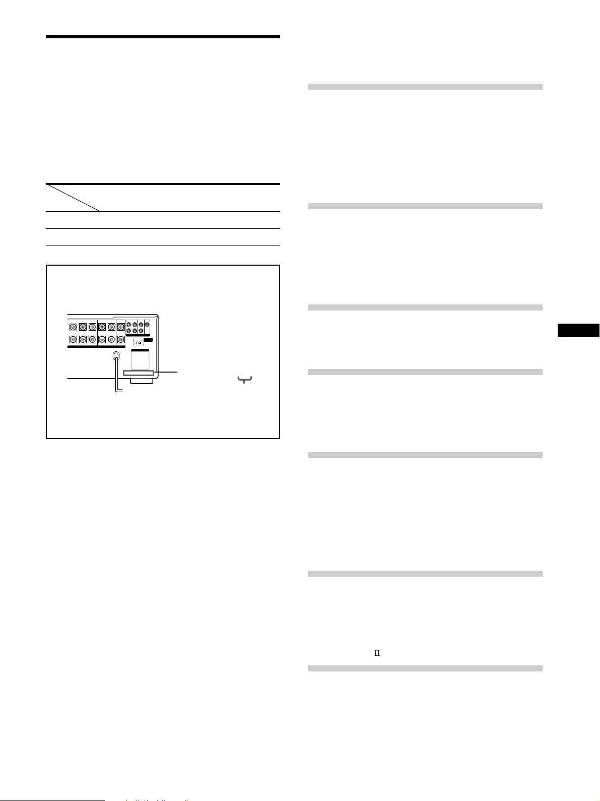
About area codes
The area code of the player you purchased is shown on the
lower portion of the rear panel (see the illustration below).
FRONT
REAR
SUB WOOFER
BA
LRL
Any differences in operation, according to the area code, are
clearly indicated in the text, for example, “Models of area
code AA only”.
REARFRONT CENTER
RL
SPEAKERS IMPEDANCE USE 4 – 16Ω
L
R
PRE OUT
4 Ω 8 Ω
AC OUTLET
CENTER
IMPEDANCE
SELECTOR
4-XXX-XXX-XX AA
Area code
TABLE OF CONTENTS
Hooking Up the Components 4
Unpacking 4
Antenna Hookups 5
Audio Component Hookups 6
Video Component Hookups 8
Digital Component Hookups 9
5.1CH Input Hookups 11
Other Hookups 12
Hooking Up and Setting Up the
Speaker System 15
Speaker System Hookup 16
Performing Initial Setup Operations 18
Multi Channel Surround Setup 19
Before You Use Your Receiver 23
Location of Parts and Basic
Operations 26
Front Panel Parts Description 26
Enjoying Surround Sound 31
Selecting a Sound Field 32
Understanding the Multi-Channel Surround
Displays 36
Customizing Sound Fields 38
GB
Conventions
• The instructions in this manual describe the controls on
the receiver. You can also use the controls on the
supplied remote if they have the same or similar names
as those on the receiver. For details on the use of your
remote, refer to the separate operating instructions
supplied with the remote.
• The following icon is used in this manual:
z Indicates hints and tips for making the task easier.
This receiver incorporates Dolby
* Digital and Pro Logic
Surround and the DTS** Digital Surround System.
Manufactured under license from Dolby Laboratories.
*
“Dolby”, “AC-3”, “Pro Logic” and the double-D symbol ; are
trademarks of Dolby Laboratories.
Confidential unpublished Works. © 1992-1997 Dolby Laboratories.
All rights reserved.
Manufactured under license from Digital Theater Systems, Inc. US
**
Pat. No. 5,451,942 and other worldwide patents issued and pending.
“DTS” and “DTS Digital Surround” are trademarks of Digital
Theater Systems, Inc. © 1996 Digital Theater Systems, Inc. All
rights reserved.
Receiving Broadcasts 43
Storing FM Stations Automatically
(AUTOBETICAL)*** 44
Direct Tuning 45
Automatic Tuning 45
Preset Tuning 46
Using the Radio Data System (RDS)*** 47
***Models of area code CED only.
Other Operations 50
Naming Preset Stations and Program Sources 51
Recording 51
Using the Sleep Timer 52
Adjustments Using the SET UP Button 53
CONTROL A1 Control System 54
Additional Information 56
Troubleshooting 56
Specifications 58
Glossary 61
Tables of Settings Using SUR, LEVEL, EQ, and SET
UP buttons 62
Index 64
3
GB
Page 4

Hooking Up
Unpacking
the
Components
This chapter describes how to connect
various audio and video components
to the receiver. Be sure to read the
sections for the components you have
before you actually connect them to
the receiver.
Check that you received the following items with the
remote:
• FM wire antenna (1)
• AM loop antenna (1)
Models of area code U, CA only
• Audio/video/control S connecting cord (1)
• Control S connecting cord (1)
STR-DB940 only
• Remote commander RM-LJ304 (remote) (1)
• R6 (size-AA) batteries (3)
STR-DB840 only
• Models of area code CED only
– Remote commander RM-PP404 (remote) (1)
– R6 (size-AA) batteries (2)
• Models of other area codes
– Remote commander RM-LP204 (remote) (1)
– R6 (size-AA) batteries (3)
Inserting batteries into the remote
Insert batteries with the + and – properly oriented in the
battery compartment. When using the remote, point it at
the remote sensor
For details, refer to the operating instructions supplied
with your remote.
on the receiver.
z
When to replace batteries
Under normal conditions, the batteries should last for about
3 months (alkaline batteries) or 2 months (manganese batteries).
When the remote no longer operates the receiver, replace all
batteries with new ones.
Notes
• Do not leave the remote in an extremely hot or humid place.
• Do not use a new battery with an old one.
• Do not expose the remote sensor to direct sunlight or lighting
apparatuses. Doing so may cause a malfunction.
• If you don’t use the remote for an extended period of time,
remove the batteries to avoid possible damage from battery
leakage and corrosion.
• This remote is designed for use with alkaline batteries only. Do
not use a combination of different battery types.
Before you get started
• Turn off the power to all components before making
any connections.
• Do not connect the AC power cord until all of the
connections are completed.
• Be sure to make connections firmly to avoid hum and
noise.
• When connecting an audio/video cord, be sure to
match the color-coded pins to the appropriate jacks on
the components: yellow (video) to yellow; white (left,
audio) to white; and red (right, audio) to red.
GB
4
Page 5
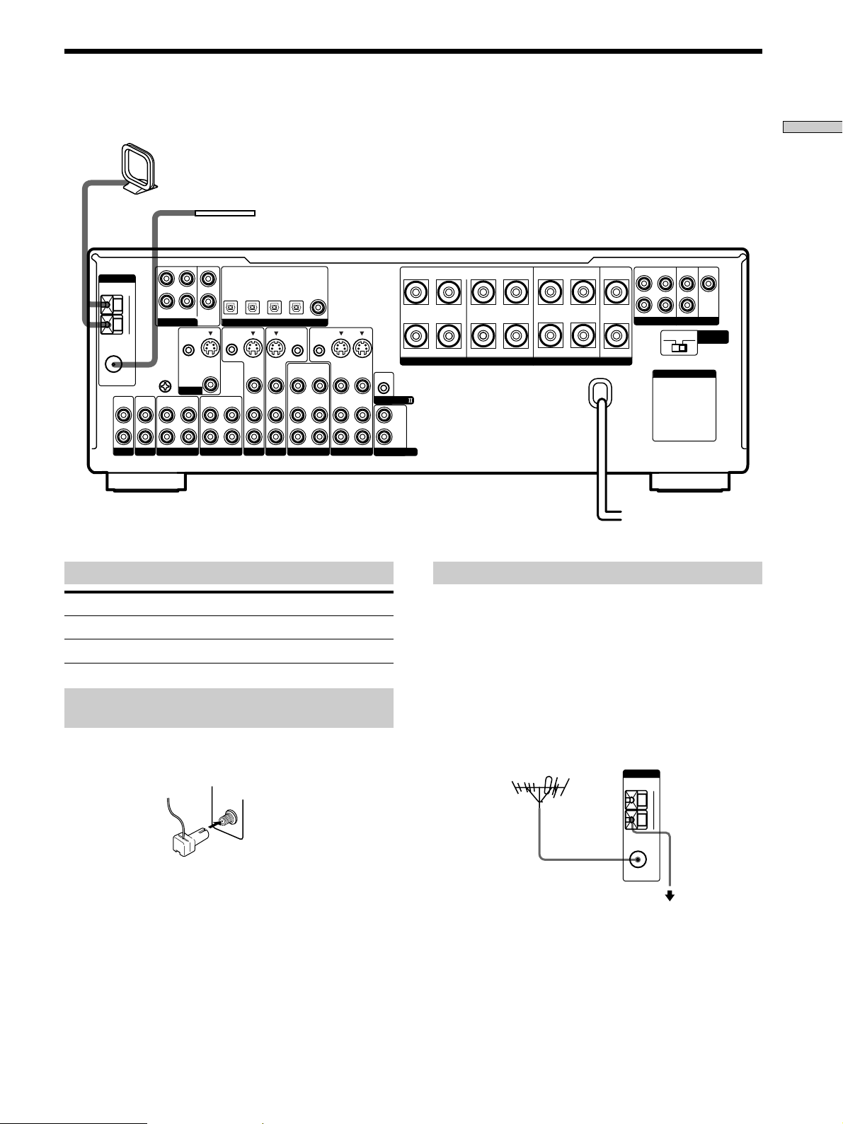
Antenna Hookups
ANTENNA
FM
75Ω
COAXIAL
L
R
PHONOINCD
AM loop antenna
(supplied)
AM
FRONT
5.1CH INPUT
U
SIGNAL
GND
U
IN
OUT
L
R
MD/DAT
REAR
CTRL S
IN
MONITOR
IN
CENTER
WOOFER
S-VIDEO
FM wire antenna
(supplied)
TV/SAT
MD/DAT
MD/DAT
OPTICAL
OPTICAL
SUB
OUT
VIDEO
OUT
TAPE
OPTICAL
OUT
CTRL S
STATUS IN
IN
IN
S-VIDEO
IN
VIDEO
AUDIO
IN
TV/SAT
IN
DIGITAL
S-VIDEO
IN
VIDEO
AUDIO
IN
DVD/LD
DVD/LD
OPTICAL
IN
CTRL S
OUT
OUT
VIDEO
AUDIO
OUT
VIDEO 2
DVD/LD
COAXIAL
IN
CTRL S
OUT
VIDEO
AUDIO
Hooking Up the Components
FRONT
REAR
SUB WOOFER
PRE OUT
4 Ω 8 Ω
AC OUTLET
CENTER
IMPEDANCE
SELECTOR
BA
REARFRONT CENTER
L
+
RLRL
RL
R
–
S-VIDEO
S-VIDEO
OUT
IN
IN
VIDEO
VIDEO
AUDIO
AUDIO
CONTROL A1
IN
OUT
IN
VIDEO 1
L
R
2ND AUDIO OUT
SPEAKERS IMPEDANCE USE 4 – 16Ω
Terminals for connecting the antennas
Connect the To the
AM loop antenna AM terminals
FM wire antenna FM 75Ω COAXIAL terminal
Assembling the supplied FM antenna
(Models of area code U, CA only)
The supplied FM wire antenna must be connected to the
supplied FM antenna adaptor.
FM
75Ω
COAXIAL
Notes on antenna hookups
• To prevent noise pickup, keep the AM loop antenna
away from the receiver and other components.
• Be sure to fully extend the FM wire antenna.
• After connecting the FM wire antenna, keep it as
horizontal as possible.
z
If you have poor FM reception
Use a 75-ohm coaxial cable (not supplied) to connect the receiver
to an outdoor FM antenna as shown below.
Outdoor FM antenna Receiver
Important
If you connect the receiver to an outdoor antenna, ground
it against lightning. To prevent a gas explosion, do not
connect the ground wire to a gas pipe.
ANTENNA
AM
U
FM
75Ω
COAXIAL
To ground
Ground wire
(not supplied)
Note
Do not use the U SIGNAL GND terminal for grounding the
receiver.
GB
5
Page 6
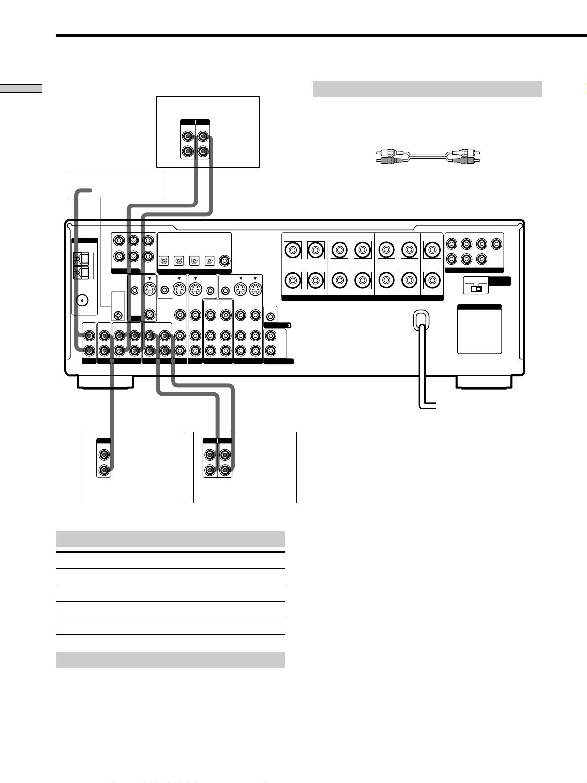
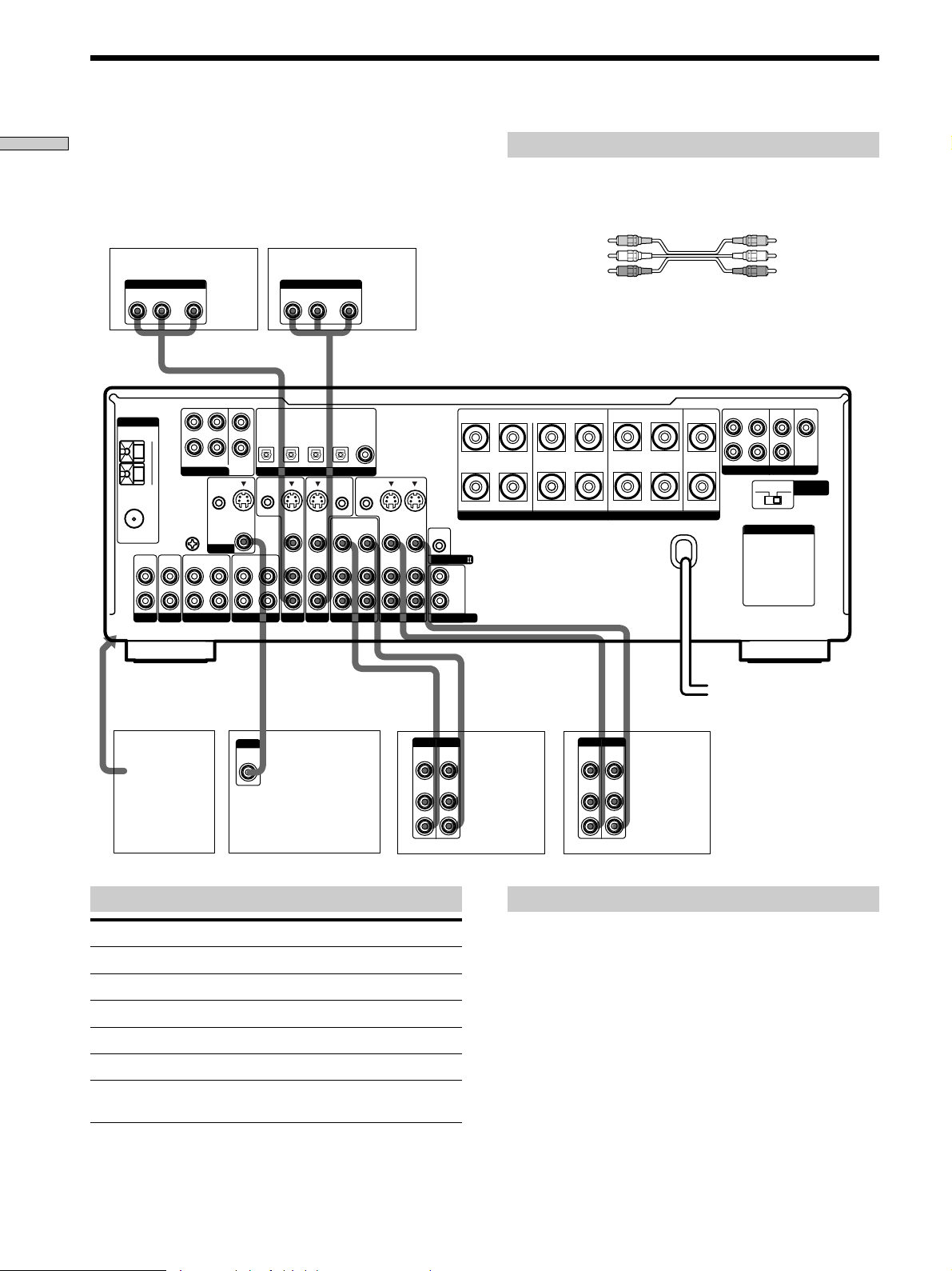
Audio Component Hookups
Hooking Up the Components
STR-DB940
Turntable
ANTENNA
FM
75Ω
COAXIAL
L
R
PHONOINCD
AM
U
IN
L
R
FRONT
REAR
5.1CH INPUT
CTRL S
SIGNAL
GND
U
MONITOR
OUT
MD/DAT
CENTER
SUB
WOOFER
IN
S-VIDEO
VIDEO
IN
Required cords
MD/DAT deck
INPUT OUTPUT
LINE
LINE
L
R
ç
Audio cords (not supplied)
When connecting a cord, be sure to match the color-coded pins to
the appropriate jacks on the components.
White (L) White (L)
Red (R) Red (R)
ç
INOUT
DVD/LD
TV/SAT
IN
IN
IN
OPTICAL
IN
DIGITAL
S-VIDEO
IN
VIDEO
AUDIO
IN
DVD/LD
DVD/LD
OPTICAL
IN
CTRL S
OUT
OUT
VIDEO
AUDIO
OUT
VIDEO 2
COAXIAL
IN
CTRL S
OUT
VIDEO
AUDIO
FRONT
REAR
SUB WOOFER
BA
REARFRONT CENTER
L
CENTER
+
RLRL
RL
–
S-VIDEO
S-VIDEO
OUT
IN
IN
VIDEO
AUDIO
OUT
VIDEO 1
IN
VIDEO
AUDIO
IN
CONTROL A1
L
R
2ND AUDIO OUT
SPEAKERS IMPEDANCE USE 4 – 16Ω
R
PRE OUT
4 Ω 8 Ω
AC OUTLET
IMPEDANCE
SELECTOR
MD/DAT
MD/DAT
OPTICAL
OPTICAL
OUT
CTRL S
STATUS IN
S-VIDEO
OUT
VIDEO
AUDIO
IN
OUT
TV/SAT
TAPE
ç
ç
OUTPUT
LINE
L
R
CD player
Jacks for connecting audio components
Connect a To the
Turntable PHONO jacks
CD player CD jacks
Tape deck TAPE jacks
MD deck or DAT deck MD/DAT jacks
Note on audio component hookups
If your turntable has a ground wire, connect it to the
U SIGNAL GND terminal on the receiver.
INPUT OUTPUT
LINE
LINE
L
R
Tape deck
GB
6
Page 7
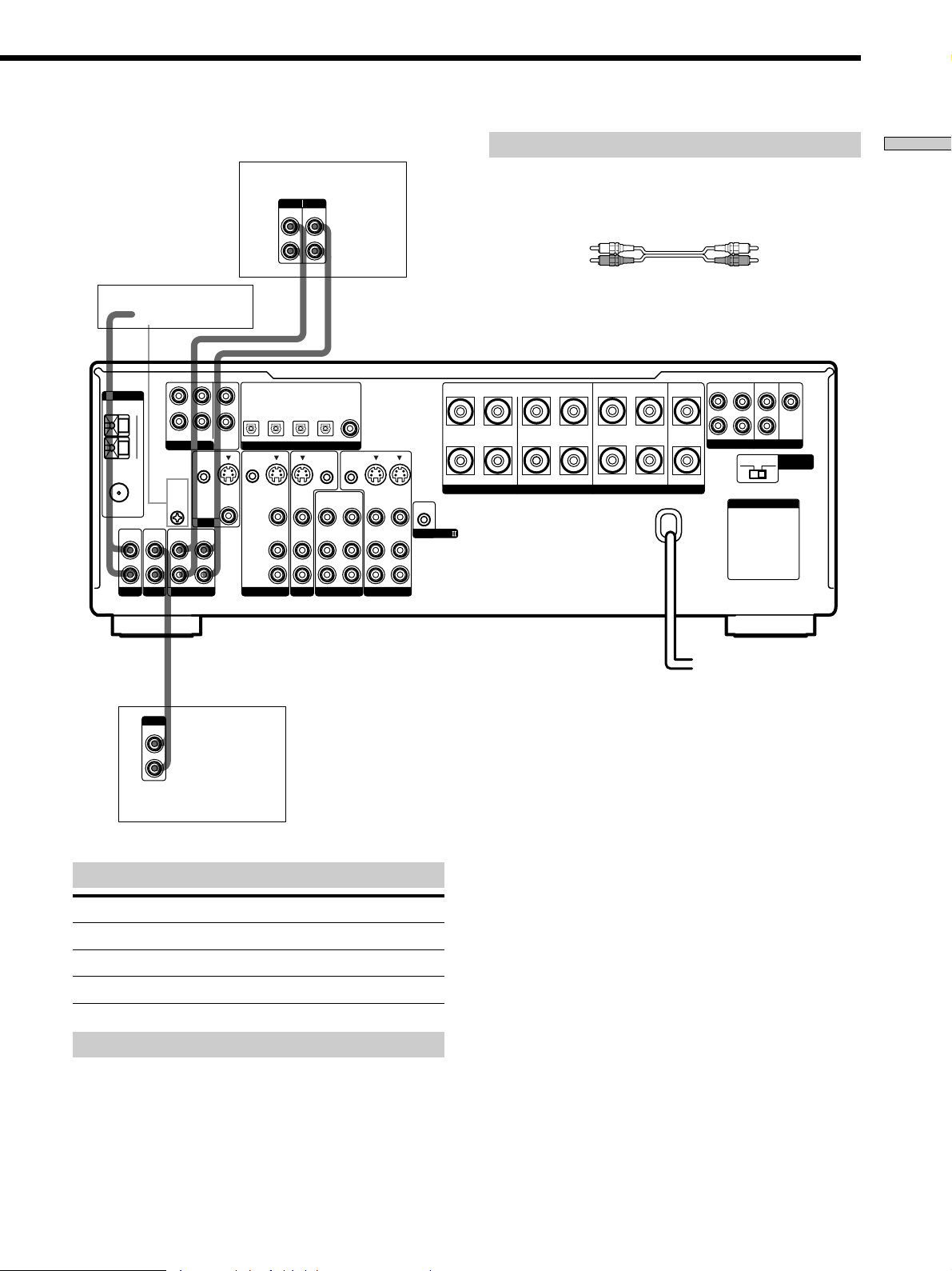
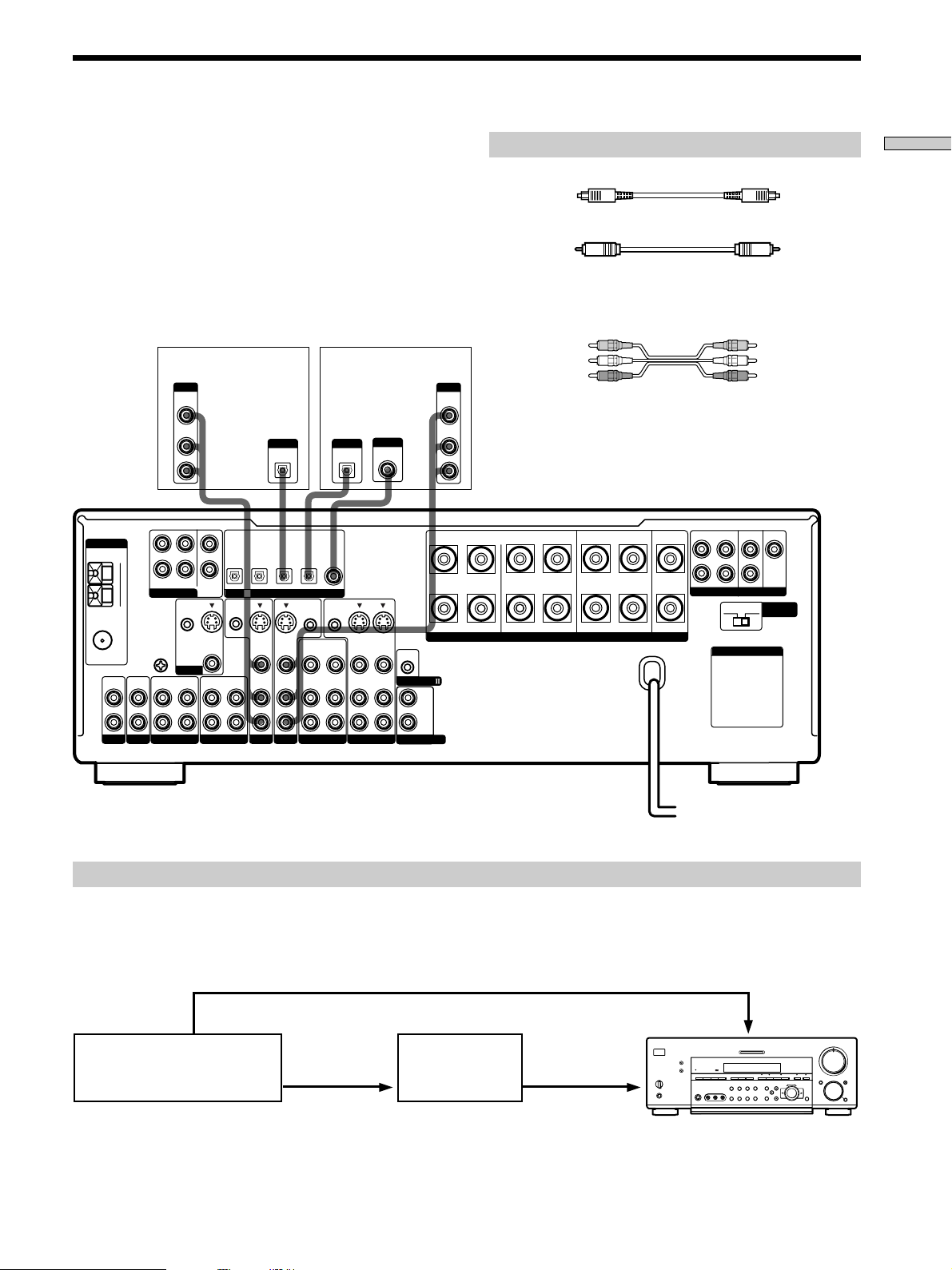
STR-DB840
MD/Tape deck
INPUT OUTPUT
LINE
LINE
L
R
ç
Required cords
Audio cords (not supplied)
When connecting a cord, be sure to match the color-coded pins to
the appropriate jacks on the components.
White (L) White (L)
Red (R) Red (R)
Hooking Up the Components
ANTENNA
FM
75Ω
COAXIAL
L
R
PHONOINCD
Turntable
AM
U
IN
OUTPUT
LINE
L
R
FRONT
REAR
5.1CH INPUT
CTRL S
SIGNAL
GND
U
MONITOR
OUT
MD/TAPE
L
R
ç
INOUT
TV/SAT
MD/TAPE
MD/TAPE
OPTICAL
OPTICAL
OPTICAL
IN
OUT
CENTER
SUB
WOOFER
IN
S-VIDEO
OUT
VIDEO
IN
CTRL S
STATUS IN
TV/SAT
S-VIDEO
IN
VIDEO
AUDIO
IN
DIGITAL
S-VIDEO
VIDEO
AUDIO
DVD/LD
DVD/LD
DVD/LD
COAXIAL
OPTICAL
IN
IN
IN
BA
REARFRONT CENTER
FRONT
REAR
L
SUB WOOFER
CENTER
+
RLRL
CTRL S
CTRL S
OUT
OUT
S-VIDEO
VIDEO 2
IN
VIDEO
AUDIO
IN
OUT
VIDEO
AUDIO
OUT
VIDEO 1
IN
OUT
VIDEO
AUDIO
IN
OUT
S-VIDEO
IN
VIDEO
AUDIO
IN
–
SPEAKERS IMPEDANCE USE 4 – 16Ω
CONTROL A1
L
R
RL
R
PRE OUT
4 Ω 8 Ω
AC OUTLET
IMPEDANCE
SELECTOR
CD player
Jacks for connecting audio components
Connect a To the
Turntable PHONO jacks
CD player CD jacks
MD deck or tape deck MD/TAPE jacks
Note on audio component hookups
If your turntable has a ground wire, connect it to the
U SIGNAL GND terminal on the receiver.
GB
7
Page 8
Video Component Hookups
Hooking Up the Components
TV or satellite tuner
OUTPUT
AUDIO OUT VIDEO
L
R
ANTENNA
FM
75Ω
COAXIAL
OUT
L
AM
FRONT
5.1CH INPUT
U
SIGNAL
CENTER
R
SUB
REAR
WOOFER
CTRL S
IN
GND
S-VIDEO
U
OUT
MD/DAT
MONITOR
IN
IN
L
R
PHONOINCD
OUT
VIDEO
OUT
DVD or LD player
AUDIO OUT VIDEO
R
MD/DAT
MD/DAT
OPTICAL
OPTICAL
IN
OUT
CTRL S
STATUS IN
S-VIDEO
IN
VIDEO
AUDIO
IN
IN
TAPE
TV/SAT
OUTPUT
L
TV/SAT
OPTICAL
IN
DIGITAL
S-VIDEO
IN
VIDEO
AUDIO
IN
DVD/LD
DVD/LD
OPTICAL
CTRL S
OUT
OUT
VIDEO
AUDIO
IN
OUT
OUT
VIDEO 2
DVD/LD
COAXIAL
IN
CTRL S
OUT
VIDEO
AUDIO
Required cords
Audio/video cords (not supplied)
When connecting a cord, be sure to match the color-coded pins to
the appropriate jacks on the components.
Yellow (video) Yellow (video)
White (L/audio) White (L/audio)
Red (R/audio) Red (R/audio)
Video cord for connecting a TV monitor
You can use the video cord of the supplied audio/video/control
S cord. (Models of area code U, CA only. See page 12 for details.)
FRONT
REAR
SUB WOOFER
PRE OUT
4 Ω 8 Ω
AC OUTLET
CENTER
IMPEDANCE
SELECTOR
BA
REARFRONT CENTER
L
+
RLRL
RL
R
–
S-VIDEO
S-VIDEO
OUT
IN
IN
VIDEO
AUDIO
OUT
VIDEO 1
IN
VIDEO
AUDIO
IN
CONTROL A1
L
R
2ND AUDIO OUT
SPEAKERS IMPEDANCE USE 4 – 16Ω
To the front panel
Camcorder
or video
game
INPUT
VIDEO
IN
VIDEO
AUDIO
IN
IN
TV monitor
Jacks for connecting video components
Connect a To the
TV or satellite tuner TV/SAT jacks
VCR VIDEO 1 jacks
Additional VCR VIDEO 2 jacks
DVD or LD player DVD/LD jacks
TV monitor
Camcorder or video game VIDEO 3 INPUT jacks on the
1)
For STR-DB940, you can display the SURROUND, LEVEL,
EQUALIZER parameters by pressing the ON SCREEN button
on the remote.
1)
MONITOR VIDEO OUT jack
front panel
Ç
OUTPUTINPUT
VIDEO
OUT
AUDIO
OUT
INOUT
Ç
INOUT
Ç
Ç
OUTPUTINPUT
VIDEO
VIDEO
IN
OUT
AUDIO
AUDIO
OUT
IN
L
R
VCR
Note on video component hookups
You can connect your TV’s audio output jacks to the TV/
SAT AUDIO IN jacks on the receiver and apply sound
effects to the audio from the TV. In this case, do not
connect the TV’s video output jack to the TV/SAT VIDEO
IN jack on the receiver. If you are connecting a separate
TV tuner (or satellite tuner), connect both the audio and
video output jacks to the receiver as shown above.
z
When using the S-video jacks instead of the video jacks
Your monitor must also be connected via an S-video jack. S-video
signals are on a separate bus from the video signals and will not
be output through the video jacks.
L
R
VCR
GB
8
Page 9
Digital Component Hookups
Connect the digital output jacks of your DVD player and
satellite tuner (etc.) to the receiver’s digital input jacks to
bring the multi channel surround sound of a movie
theater into your home. To enjoy full effect of multi
channel surround sound, five speakers (two front
speakers, two rear speakers, and a center speaker) and a
sub woofer are required. You can also connect an LD
player with an RF OUT jack via an RF demodulator, like
the Sony MOD-RF1 (not supplied).
ANTENNA
FM
75Ω
COAXIAL
L
R
PHONOINCD
TV or satellite tuner
OUTPUT
VIDEO
OUT
AUDIO
OUT
L
R
L
GND
U
OUT
MD/DAT
R
REAR
CTRL S
IN
MONITOR
IN
CENTER
SUB
WOOFER
S-VIDEO
OUT
VIDEO
OUT
TAPE
AM
FRONT
5.1CH INPUT
U
SIGNAL
IN
MD/DAT
OPTICAL
OUT
CTRL S
STATUS IN
IN
MD/DAT
OPTICAL
IN
S-VIDEO
IN
VIDEO
AUDIO
IN
TV/SAT
OUTPUT
DIGITAL
OPTICAL
DIGITAL
DVD/LD
DVD or LD player (etc.)*
OUTPUT
DIGITAL
OPTICAL
IN
VIDEO
IN
DVD/LD
DVD/LD
COAXIAL
OPTICAL
IN
IN
CTRL S
CTRL S
OUT
OUT
S-VIDEO
OUT
VIDEO 2
IN
VIDEO
AUDIO
IN
OUT
VIDEO
AUDIO
OUT
VIDEO 1
IN
OUT
VIDEO
AUDIO
TV/SAT
OPTICAL
S-VIDEO
AUDIO
OUTPUT
DIGITAL
COAXIAL
S-VIDEO
IN
VIDEO
AUDIO
IN
+
–
CONTROL A1
2ND AUDIO OUT
Required cords
Optical digital cords (not supplied)
Black Black
Coaxial digital cord (not supplied)
Yellow Yellow
Audio/video cords (not supplied)
When connecting a cord, be sure to match the color-coded pins to
the appropriate jacks on the components.
Yellow (video) Yellow (video)
White (L/audio) White (L/audio)
OUTPUT
VIDEO
AUDIO
RLRL
L
R
Red (R/audio) Red (R/audio)
OUT
OUT
L
R
BA
SPEAKERS IMPEDANCE USE 4 – 16Ω
REARFRONT CENTER
RL
FRONT
REAR
L
R
PRE OUT
4 Ω 8 Ω
AC OUTLET
SUB WOOFER
CENTER
IMPEDANCE
SELECTOR
Hooking Up the Components
Make either coaxial or optical connections. We recommend making coaxial connections instead of optical connections.
*
Example of LD player connected via an RF demodulator
Please note that you cannot connect an LD player’s AC-3 RF OUT jack directly to this unit’s digital input jacks. You must
first convert the RF signal to either an optical or coaxial digital signal. Connect the LD player to the RF demodulator, then
connect the RF demodulator’s optical or coaxial digital output to this unit’s OPTICAL or COAXIAL DVD/LD IN jack.
Refer to the instruction manual supplied with your RF Demodulator for details on AC-3 RF hookups.
DVD/LD
?/1
•
•
•
•
VIDEO IN
–+ –+
5
•
•
•
46
•
•
•
3
•
•
•
2
•
•
•
1
•
•
•
–
+
0
+
–
VIDEO OUT
AC-3 RF
OUT
DIGITAL
DIGITAL
DVD/LD IN
DVD/LD IN
(COAXIAL)
RF demodulatorLD player
(COAXIAL)
or (OPTICAL)
(OPTICAL)
Note
When making connections as shown above, be sure to set INPUT MODE (5 on page 27) manually. This unit may not operate correctly if
INPUT MODE is set to “AUTO.”
9
•
•
•
•
•
•
7
•
•
•
8
•
•
•
9
•
•
•
10
GB
Page 10
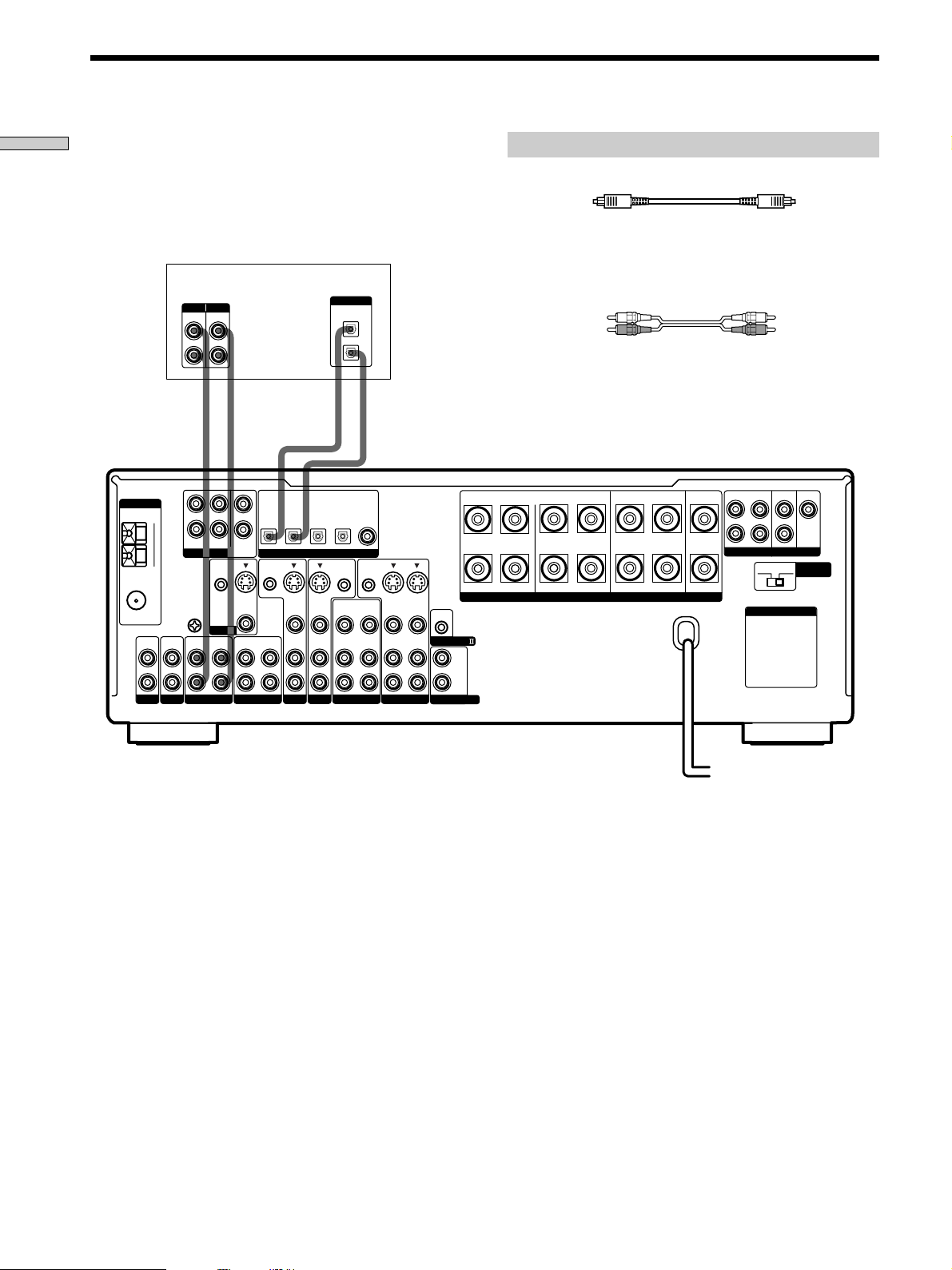
Digital Component Hookups
Hooking Up the Components
Connect the digital output jacks of your MD or DAT deck
to the receiver’s digital input jack and connect the digital
input jacks of your MD or DAT deck to the receiver’s
digital output jack. These connections allow you to make
digital recordings of a CDs played back through your
DVD (or LD player) and satellite broadcasts.
MD or DAT deck
INPUT OUTPUT
LINE
LINE
L
R
ç
ANTENNA
FM
75Ω
COAXIAL
L
R
PHONOINCD
AM
U
IN
L
R
FRONT
REAR
5.1CH INPUT
CTRL S
SIGNAL
GND
U
MONITOR
OUT
MD/DAT
CENTER
WOOFER
IN
IN
ç
INOUT
SUB
STATUS IN
S-VIDEO
OUT
VIDEO
OUT
TAPE
MD/DAT
OPTICAL
OUT
CTRL S
Required cords
Optical digital cords (not supplied)
Black Black
Audio cords (not supplied)
When connecting a cord, be sure to match the color-coded pins to
the appropriate jacks on the components.
DIGITAL
OPTICAL
IN
OUT
White (L) White (L)
Red (R) Red (R)
ç
ç
INOUT
DVD/LD
TV/SAT
IN
VIDEO
AUDIO
IN
IN
OPTICAL
IN
DIGITAL
S-VIDEO
IN
VIDEO
AUDIO
IN
DVD/LD
DVD/LD
OPTICAL
IN
CTRL S
OUT
OUT
VIDEO
AUDIO
OUT
VIDEO 2
COAXIAL
IN
CTRL S
OUT
VIDEO
AUDIO
FRONT
REAR
SUB WOOFER
BA
REARFRONT CENTER
L
CENTER
+
RLRL
RL
–
S-VIDEO
S-VIDEO
OUT
IN
IN
VIDEO
VIDEO
AUDIO
AUDIO
CONTROL A1
IN
OUT
IN
VIDEO 1
L
R
2ND AUDIO OUT
SPEAKERS IMPEDANCE USE 4 – 16Ω
R
PRE OUT
4 Ω 8 Ω
AC OUTLET
IMPEDANCE
SELECTOR
MD/DAT
OPTICAL
S-VIDEO
IN
TV/SAT
Notes
• Please note that you cannot make a digital recording of a digital multi channel surround signal.
• To make a digital recording from your CD player, connect the CD player’s digital output directly to the digital input on your MD or DAT
deck. Refer to the instructions supplied with your CD player and MD or DAT deck for details.
• The DVD/LD IN OPTICAL and COAXIAL jacks are compatible with 96 kHz, 48 kHz, 44.1 kHz and 32 kHz sampling frequencies. The
other OPTICAL jacks are compatible with 48 kHz, 44.1 kHz and 32 kHz sampling frequencies.
• It is not possible to record analog signals to TAPE and VIDEO with only digital connections. To record analog signals, make analog
connections. To record digital signals, make digital connections.
• Input signals with 96 kHz sampling frequencies to the DVD/LD IN OPTICAL or COAXIAL jacks. Using other jacks may result in
intermittent sound.
GB
10
Page 11
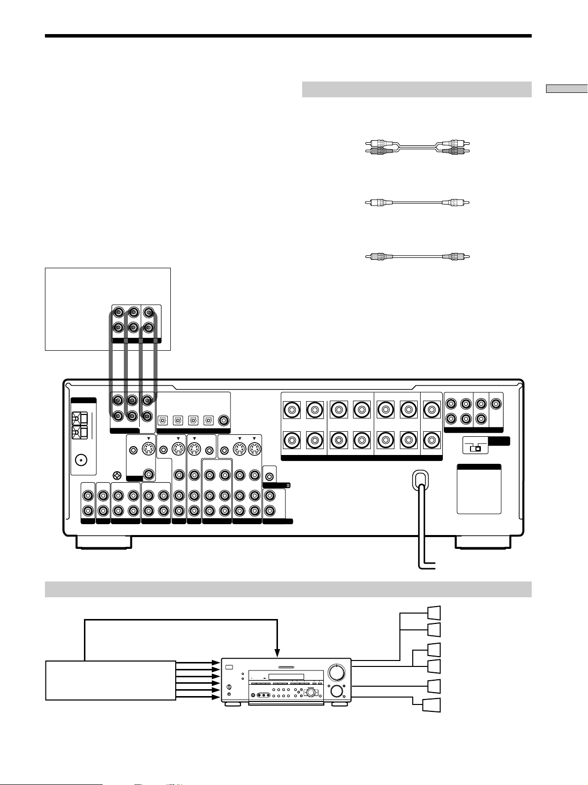
5.1CH Input Hookups
Although this receiver incorporates a multi channel
decoder, it is also equipped with 5.1CH INPUT jacks.
These connections allow you to enjoy multichannel
software encoded in formats other than Dolby Digital
(AC-3) and DTS. If your DVD player is equipped with
5.1CH OUTPUT jacks, you can connect them directly to
this unit to enjoy the sound of the DVD player’s multi
channel decoder. Alternatively, the 5.1CH INPUT jacks
can be used to connect an external multi channel decoder.
To fully enjoy multi channel surround sound, you will
need five speakers (two front speakers, two rear speakers,
and a center speaker) and a sub woofer. Refer to the
instruction manual supplied with your DVD player, multi
channel decoder, etc., for details on the 5.1 channel input
hookups.
DVD player,
Multichannel decoder, etc.
L
CENTER
R
FRONT
REAR
SUB WOOFER
5.1CH OUTPUT
Required cords
Audio cords (not supplied)
Two for the 5.1CH INPUT FRONT and REAR jacks
White (L) White (L)
Red (R) Red (R)
Monaural audio cords (not supplied)
Two for the 5.1CH INPUT CENTER and SUB WOOFER jacks
Black Black
Video cord (not supplied)
One for the DVD/LD VIDEO IN jacks (etc.)
Yellow Yellow
Note
When using the connections described below, adjust the level of
your surround speakers and sub woofer from the DVD player or
multichannel decoder.
Hooking Up the Components
ANTENNA
FM
75Ω
COAXIAL
L
R
PHONOINCD
L
AM
R
FRONT
REAR
5.1CH INPUT
SIGNAL
GND
CTRL S
U
U
OUT
MD/DAT
MONITOR
IN
MD/DAT
OPTICAL
CENTER
SUB
WOOFER
CTRL S
STATUS IN
IN
S-VIDEO
OUT
VIDEO
OUT
IN
TAPE
OPTICAL
OPTICAL
IN
OUT
DIGITAL
S-VIDEO
S-VIDEO
IN
VIDEO
AUDIO
IN
IN
TV/SAT
DVD/LD
TV/SAT
MD/DAT
IN
IN
VIDEO
AUDIO
IN
DVD/LD
OPTICAL
IN
CTRL S
OUT
OUT
VIDEO
AUDIO
OUT
VIDEO 2
DVD/LD
COAXIAL
IN
CTRL S
OUT
VIDEO
AUDIO
BA
+
RLRL
–
S-VIDEO
S-VIDEO
OUT
IN
IN
VIDEO
VIDEO
AUDIO
AUDIO
CONTROL A1
IN
OUT
IN
VIDEO 1
L
R
2ND AUDIO OUT
Example of a DVD player hookup using the 5.1CH INPUT jacks
VIDEO OUT
5.1 CH INPUT
DVD player
Note
See page 16 for details on speaker system hookup.
?/1
•
•
•
•
DVD/LD
IN VIDEO etc.
–+ –+
–
+
5
•
•
•
•
•
•
46
•
•
•
•
•
•
3
7
•
•
•
•
•
2
•
•
•
•
1
9
•
•
•
•
•
•
0
10
+
–
REARFRONT CENTER
RL
SPEAKERS IMPEDANCE USE 4 – 16Ω
SPEAKERS
FRONT
•
8
•
•
SPEAKERS
REAR/CENTER
SUB WOOFER
FRONT
REAR
SUB WOOFER
PRE OUT
4 Ω 8 Ω
CENTER
IMPEDANCE
SELECTOR
L
R
AC OUTLET
Front Speaker (L)
Front Speaker (R)
Rear Speaker (L)
Rear Speaker (R)
Center Speaker
Active Woofer
11
GB
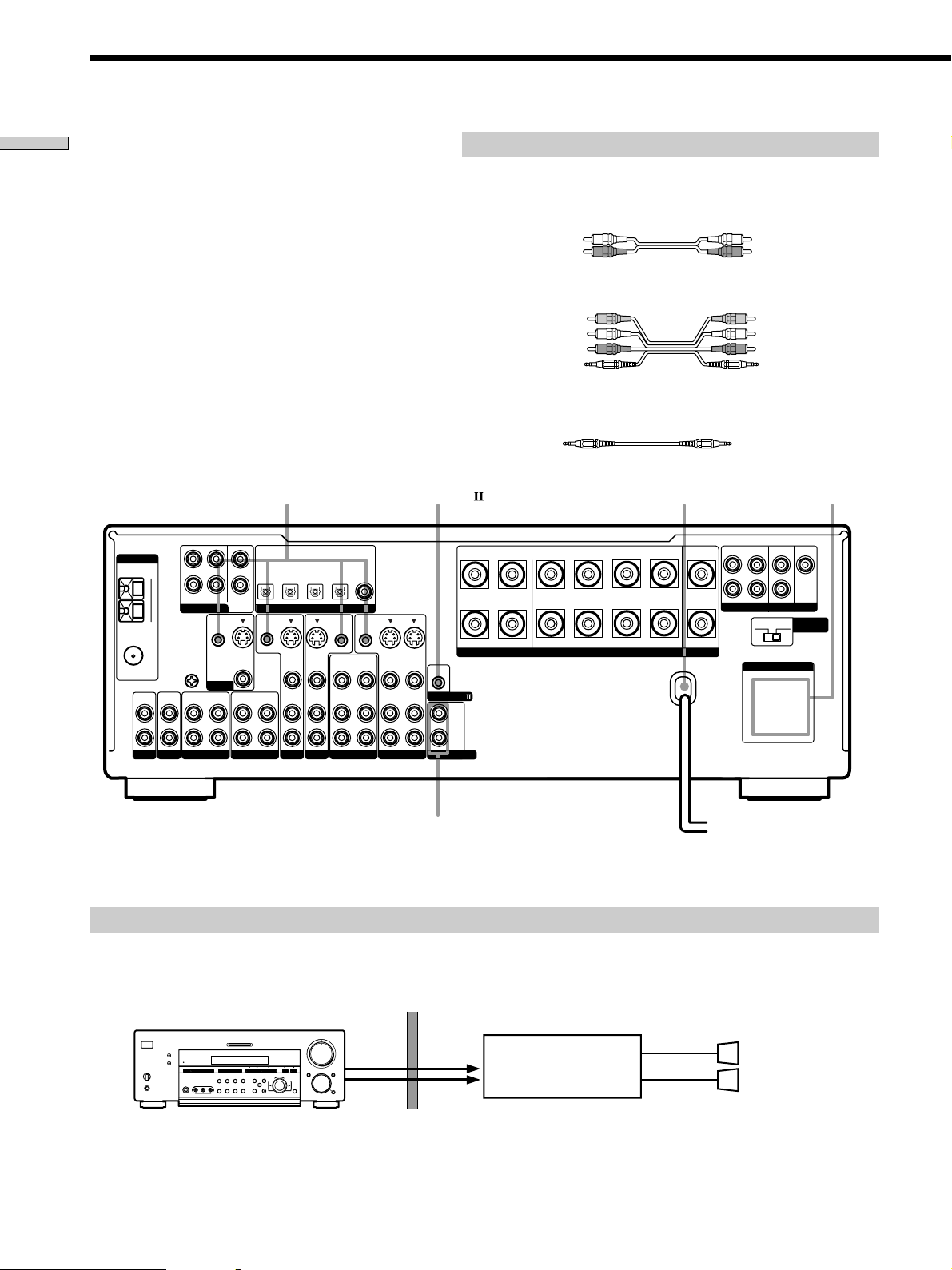
Page 12
Other Hookups
Hooking Up the Components
CTRL S (STATUS) IN/OUT** CONTROL A1
ANTENNA
FM
75Ω
COAXIAL
L
R
PHONOINCD
AM
U
IN
L
R
FRONT
REAR
5.1CH INPUT
CTRL S
SIGNAL
GND
U
MONITOR
OUT
MD/DAT
CENTER
SUB
WOOFER
IN
S-VIDEO
VIDEO
IN
Required cords
Audio cords (not supplied)
When connecting a cord, be sure to match the color-coded pins to the
appropriate jacks on the components.
White (L) White (L)
Red (R) Red (R)
Audio/video/control S connecting cord (1)**
Yellow (video) A
White (L/audio) B
Red (R/audio) C
Black (control S) D
Control S connecting cord (1)**
Black E Black E
AC power cord
DVD/LD
TV/SAT
IN
IN
IN
OPTICAL
IN
DIGITAL
S-VIDEO
IN
VIDEO
AUDIO
IN
DVD/LD
DVD/LD
OPTICAL
IN
CTRL S
OUT
OUT
VIDEO
AUDIO
OUT
VIDEO 2
COAXIAL
CTRL S
VIDEO
AUDIO
IN
BA
REARFRONT CENTER
+
RLRL
S-VIDEO
IN
VIDEO
AUDIO
IN
–
SPEAKERS IMPEDANCE USE 4 – 16Ω
CONTROL A1
L
R
2ND AUDIO OUT
OUT
S-VIDEO
OUT
IN
VIDEO
AUDIO
OUT
IN
VIDEO 1
RL
MD/DAT
MD/DAT
OPTICAL
OPTICAL
OUT
CTRL S
STATUS IN
S-VIDEO
OUT
VIDEO
AUDIO
IN
OUT
TAPE
TV/SAT
Yellow (video) A
White (L/audio) B
Red (R/audio) C
Black (control S) D
AC OUTLET
FRONT
REAR
SUB WOOFER
L
R
PRE OUT
4 Ω 8 Ω
AC OUTLET
CENTER
IMPEDANCE
SELECTOR
*
2ND AUDIO OUT
(STR-DB940 only)
To a wall outlet
b
* The configuration, shape, and number of AC outlets on the rear panel varies according to the model and country to which the receiver is shipped.
** Models of area code U, CA only.
Example of a sub room hookup using the 2ND AUDIO OUT jacks (STR-DB940 only)
You can use the 2ND AUDIO OUT jacks to output the audio signal of the selected component to a stereo amplifier located
in another room. Use MODE and FUNCTION (4 on pages 26 and 27) to switch the audio signal output to the sub room.
Main room
5
•
•
•
•
•
•
46
•
•
•
•
•
?/1
•
•
•
•
–+ –+
–
+
•
3
7
AUDIO
•
•
•
•
•
•
2
8
•
•
•
•
•
•
OUT
1
9
•
•
•
•
•
•
0
10
+
–
Note
This function is not available when 5.1CH INPUT is selected.
GB
12
AUDIO
IN
Sub room
Stereo amplifier
SPEAKERS
R
L
Speaker (R)
Speaker (L)
Page 13
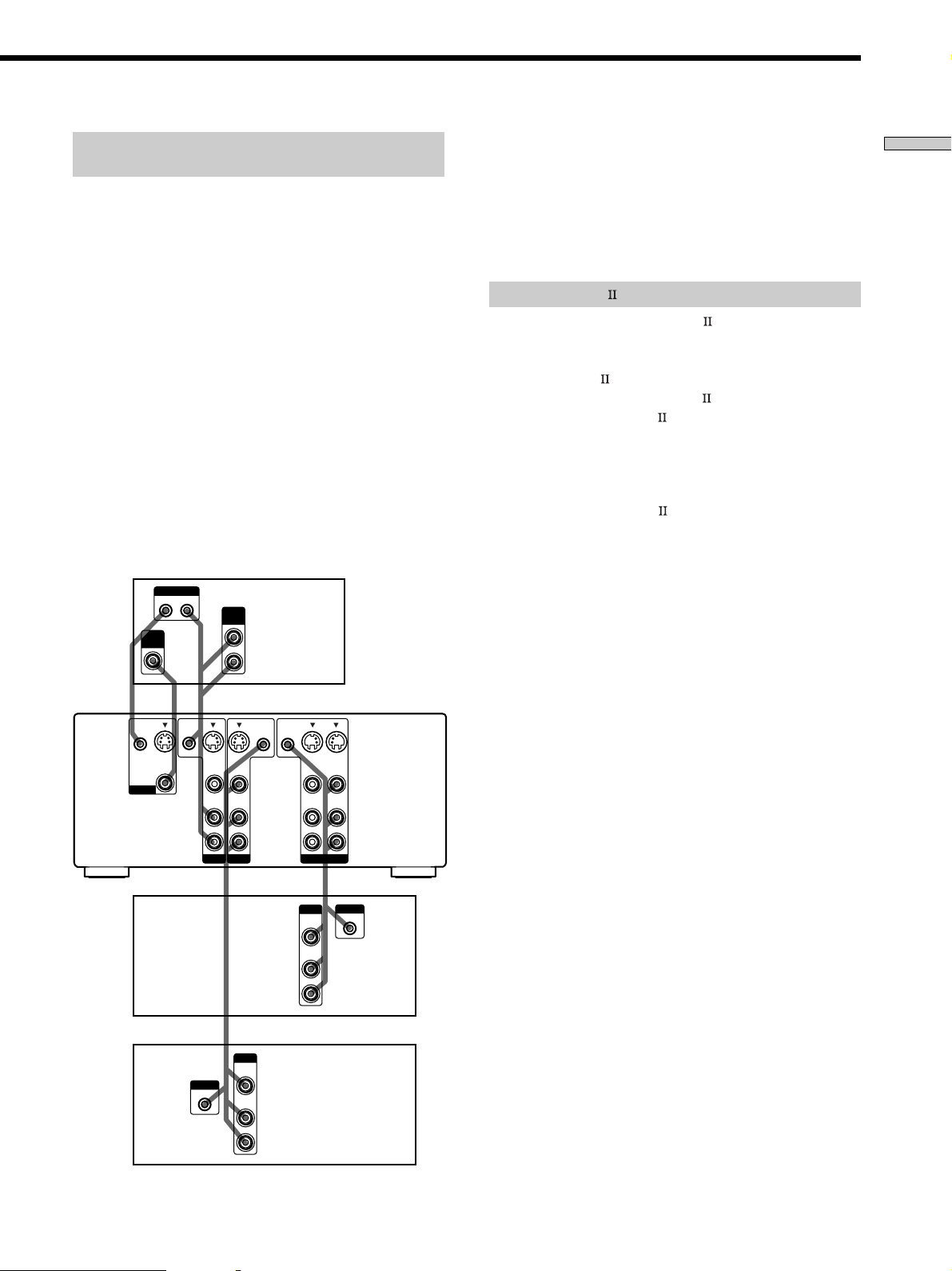
S-LINK CONTROL S hookup
(Models of area code U,CA only)
If you have a S-LINK CONTROL S-compatible Sony TV,
satellite tuner, monitor, DVD player or VCR, use an
audio/video/control S connecting cord (supplied) or a
control S connecting cord (supplied) to connect the CTRL
S (STATUS) IN (for TV, satellite tuner, or monitor) or OUT
(for VCR, etc.) jack on the receiver to the appropriate SLINK jack on the respective component. Refer to the
operating instructions supplied with your TV, satellite
tuner, monitor, VCR, etc., for details.
The following illustration is an example of S-LINK
CONTROL S hookups between the receiver, a TV, a VCR,
and a DVD player. When your TV is connected to the
receiver as shown below, the TV input mode will change
to video input whenever you turn on the receiver. When
you connect the receiver as shown below, input mode of
the receiver changes to VIDEO 1 or DVD/LD whenever
you play your VCR or DVD.
The following connections also change the input mode of
the receiver to TV whenever you operate your TV.
TV
Receiver
VIDEO
CTRL S
IN
MONITOR
IN
S-LINK
OUT IN
A
S-VIDEO
OUT
VIDEO
CTRL S
STATUS IN
DE
S-VIDEO
****
VIDEO
AUDIO
AUDIO
OUT
B
C
CTRL S
CTRL S
OUT
OUT
S-VIDEO
IN
IN
VIDEO
AUDIO
IN
IN
S-VIDEO
OUT
VIDEO
AUDIO
OUT
S-VIDEO
IN
VIDEO
AUDIO
IN
* Audio/video/control S connecting cord (Pull the video cord away
from the supplied audio/video/control S cable for connection A.)
** Control S connecting cord
Note
Refer to the instructions supplied with your TV for details
regarding the operations you can control from your TV.
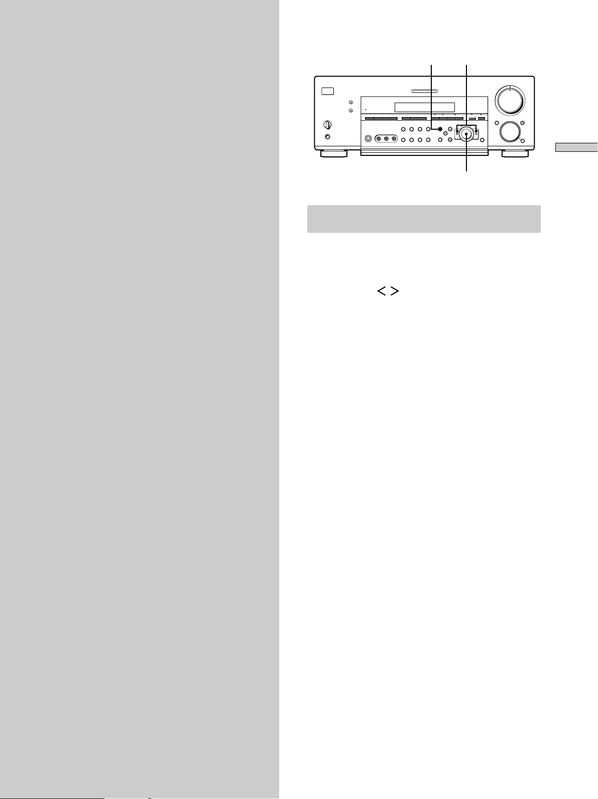
CONTROL A1 hookup
• If you have a CONTROL A1 compatible Sony
CD player, tape deck, or MD deck
Use a CONTROL A1 cord (not supplied) to connect the
CONTROL A1
MD deck to the CONTROL A1
Refer to “CONTROL A1
and the operating instructions supplied with your CD
player, tape deck, or MD deck for details.
Note
If you make CONTROL A1 connections from the receiver to
an MD deck that is also connected to a computer, do not
operate the receiver while using the “Sony MD Editor”
software. This may cause a malfunction.
• If you have a Sony CD changer with a
COMMAND MODE selector
If your CD changer’s COMMAND MODE selector can
be set to CD 1, CD 2, or CD 3, be sure to set the
command mode to “CD 1” and connect the changer to
the CD jacks on the receiver.
If, however, you have a Sony CD changer with VIDEO
OUT jacks, set the command mode to “CD 2” and
connect the changer to the VIDEO 2 jacks on the
receiver.
jack on the CD player, tape deck, or
jack on the receiver.
Control System” on page 54
Hooking Up the Components
VCR 1
DVD
player
S-LINK
IN
TV/SAT
DVD/LD
*
OUTPUT
VIDEO
OUT
AUDIO
OUT
VIDEO 1
OUTPUT
VIDEO
OUT
AUDIO
OUT
*
S-LINK
IN
13
GB
Page 14

Other Hookups
Hooking Up the Components
Connecting the AC power cord
Before connecting the AC power cord of this receiver to a
wall outlet:
• Connect the speaker system to the receiver (see page
16).
• Turn the MASTER VOLUME control to the leftmost
position (0).
Connect the AC power cord(s) of your audio/video
components to a wall outlet.
If you connect other audio/video components to the AC
OUTLET(s) on the receiver, the receiver will supply power
to the connected component(s), allowing you to turn the
whole system on or off when you turn the receiver on or
off.
Caution
Make sure that the total power consumption of the component(s)
connected to the receiver’s AC OUTLET(s) does not exceed the
wattage stated on the rear panel. Do not connect high-wattage
electrical home appliances such as electric irons, fans, or TVs to
this outlet.
Note
If the AC power cord is disconnected for about two weeks, the
receiver’s entire memory will be cleared and the demonstration
will start.
14
GB
Page 15
Hooking Up
and Setting Up
the Speaker
SET UP
?/1
•
•
•
•
–+ –+
–
+
Cursor buttons
46
•
•
•
3
•
•
•
2
•
•
•
1
•
•
•
0
+
–
5
•
•
•
•
•
•
•
•
•
7
•
•
•
8
•
•
•
9
•
•
•
10
System
This chapter describes how to hook
up your speaker system to the
receiver, how to position each speaker,
and how to set up your speakers to
enjoy multi channel surround sound.
Hooking Up and Setting Up the Speaker System
Jog dial
Brief descriptions of buttons and control
used to set up the speaker system
SET UP button: Press to enter the setup mode when
specifying speaker types and distances.
Cursor buttons ( / ): Use to select parameters after
pressing the SET UP button.
Jog dial: Use to adjust the setting of each parameter.
15
GB
Page 16
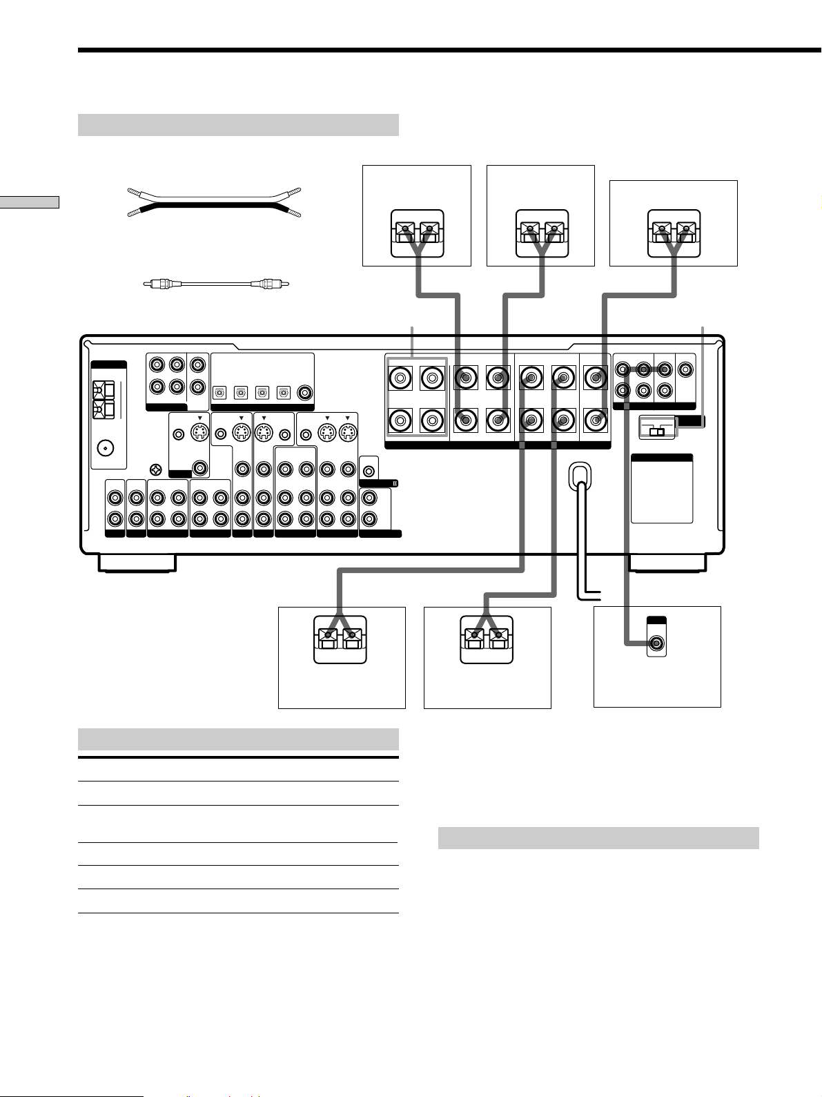
Speaker System Hookup
Required cords
Speaker cords (not supplied)
One for each front, rear, and center speaker
(+) (+)
Hooking Up and Setting Up the Speaker System
(–) (–)
Monaural audio cord (not supplied)
One for an active sub woofer
Black Black
DVD/LD
TV/SAT
ANTENNA
FM
75Ω
COAXIAL
L
R
PHONOINCD
MD/DAT
CTRL S
IN
IN
CENTER
SUB
WOOFER
S-VIDEO
OUT
VIDEO
OUT
TAPE
MD/DAT
OPTICAL
OUT
CTRL S
STATUS IN
IN
OPTICAL
S-VIDEO
VIDEO
AUDIO
TV/SAT
L
AM
R
FRONT
REAR
5.1CH INPUT
U
SIGNAL
GND
U
OUT
MD/DAT
MONITOR
IN
IN
IN
IN
OPTICAL
IN
DIGITAL
S-VIDEO
IN
VIDEO
AUDIO
IN
DVD/LD
DVD/LD
OPTICAL
CTRL S
OUT
OUT
VIDEO
AUDIO
IN
OUT
VIDEO 2
COAXIAL
IN
CTRL S
OUT
VIDEO
AUDIO
S-VIDEO
OUT
IN
VIDEO
AUDIO
OUT
IN
VIDEO 1
Front speaker (R) Front speaker (L)
S-VIDEO
IN
VIDEO
AUDIO
IN
}]
FRONT
SPEAKERS B
BA
+
RLRL
–
CONTROL A1
L
R
2ND AUDIO OUT
}
SPEAKERS IMPEDANCE USE 4 – 16Ω
REARFRONT CENTER
RL
]
Center speaker
}
FRONT
REAR
SUB WOOFER
L
R
PRE OUT
4 Ω 8 Ω
AC OUTLET
IMPEDANCE
SELECTOR
CENTER
IMPEDANCE
SELECTOR
]
}]
Terminals for connecting the speakers
Connect the To the
Front speakers (8 or 4* ohm) SPEAKERS FRONT A terminals
Additional pair of front
speakers (8 or 4* ohm)
Rear speakers (8 or 4* ohm) SPEAKERS REAR terminals
Center speaker (8 or 4* ohm) SPEAKERS CENTER terminals
Active sub woofer SUB WOOFER PRE OUT**
* See “Speaker impedance” on the next page.
** You can connect an active sub woofer to either of the two jacks. The
remaining jack can be used to connect a second active sub woofer.
SPEAKERS FRONT B terminals
INPUT
AUDIO
}
]
IN
Active sub wooferRear speaker (R) Rear speaker (L)
z
To connect certain speakers to another amplifier
Use the PRE OUT jacks. The same signal is output from both the
SPEAKERS jacks and the PRE OUT jacks. For example, if you
want to connect just the front speakers to another amplifier,
connect that amplifier to the PRE OUT FRONT L and R jacks.
Notes on speaker system hookup
• Twist the stripped ends of the speaker cords about
2/3 inch (10 mm). Be sure to match the speaker cord to
the appropriate terminal on the components: + to + and
– to –. If the cords are reversed, the sound will be
distorted and will lack bass.
• If you use front speakers with low maximum input
rating, adjust the volume carefully to avoid excessive
output on the speakers.
16
GB
Page 17
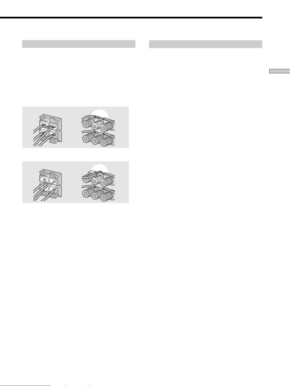
To avoid short-circuiting the speakers
Short-circuiting of the speakers may damage the receiver.
To prevent this, make sure to take the following
precautions when connecting the speakers.
Make sure the stripped ends of each speaker cord
do not touch another speaker terminal or the
stripped end of another speaker cord.
Speaker impedance
To enjoy multi channel surround, connect front, center,
and rear speakers with a nominal impedance of 8 ohms or
higher, and set the speaker IMPEDANCE SELECTOR to
“8Ω.” Check the instruction manual supplied with your
speakers if you’re not sure of their impedance. (This
information is usually printed on a label on the back of
the speaker.)
Hooking Up and Setting Up the Speaker System
Examples of poor conditions of the speaker cord
Stripped speaker cord is touching another speaker terminal.
Stripped cords are touching each other due to excessive
removal of insulation.
After connecting all the components, speakers,
and AC power cord, output a test tone to check
that all the speakers are connected correctly. For
details on outputting a test tone, see page 22.
You may connect a pair of speakers with a nominal
impedance between 4 and 8 ohms to all of the speaker
terminals. However, even if one speaker within this range
is connected, set the IMPEDANCE SELECTOR to “4Ω”.
Note
Be sure to connect front speakers with a nominal impedance of
8 ohms or higher if you want to select both sets (A+B) of front
speakers (see page 30). In this case, set the IMPEDANCE
SELECTOR to “4Ω”.
If no sound is heard from a speaker while outputting a
test tone or a test tone is output from a speaker other than
the one whose name is currently displayed on the
receiver, the speaker may be short-circuited. If this
happens, check the speaker connection again.
17
GB
Page 18
Performing Initial Setup Operations
Once you have hooked up the speakers and turned on the
power, clear the receiver’s memory. Then specify the
speaker parameters (size, position, etc.) and perform any
other initial setup operations necessary for your system.
Hooking Up and Setting Up the Speaker System
Before turning on the receiver
Make sure that you have:
• Turned MASTER VOLUME to the leftmost position (0).
• Selected the appropriate front speakers (see “wj
SPEAKERS selector” on page 30).
Clearing the receiver’s memory
Before using your receiver for the first time, or when you
want to clear the receiver’s memory, do the following.
This procedure is not necessary if the demonstration
activates when you turn the power on.
1/u
?/1
•
•
•
•
–+ –+
–
+
–
+
1 Turn off the receiver.
2 Hold down ?/1 for 5 seconds.
The currently selected function, followed by the
demonstration message appears in the display. All of
the following items are reset or cleared:
• All preset stations are reset or cleared.
• All sound field parameters are reset to their factory
settings.
• All index names (of preset stations and program
sources) are cleared.
• All adjustments made with the SET UP button are
reset to their factory settings.
• The sound field memorized for each program source
and preset stations are cleared.
•
•
•
46
•
•
•
3
•
•
•
2
•
•
•
1
•
•
•
0
Performing initial setup operations
Before using your receiver for the first time, use the SET
UP button to adjust the setup parameters so that they
correspond to your system. You can adjust the following
items. For details on how to make adjustments, see the
page in parenthesis.
• Speaker size and placement (pages 19~22).
• Speaker distance (page 19).
• Whether other components will turn on or off
automatically via the CONTROL A1
(page 53).
• Whether the display turns off or not when you press
DIMMER (page 54).
• STR-DB940 only:
– 2 way remote control system operation (page 53).
– Selecting the color of the on-screen display (page 54).
– Select the TV color system of the monitor (except for
models of area U, CA) (page 54).
Demonstration Mode
5
•
•
•
•
•
•
7
•
•
•
8
•
•
•
9
•
•
•
10
The demonstration will activate the first time you turn on
the power. When the demonstration starts, the following
message appears in the display twice:
“Now Demonstration Mode!! To finish the
demonstration, please push POWER KEY while this
message appears in the display. Thank you!”
To cancel the demonstration
Press ?/1 to turn the receiver off during the previous
message. The next time you turn the receiver on, the
demonstration will not appear.
To view the demonstration
Hold down SET UP and press ?/1 to turn on the power.
Note
Running the demonstration will clear the receiver’s
memory. For details on what will be cleared, see “Clearing
the receiver's memory” on this page.
control system
18
GB
Page 19
Multi Channel Surround Setup
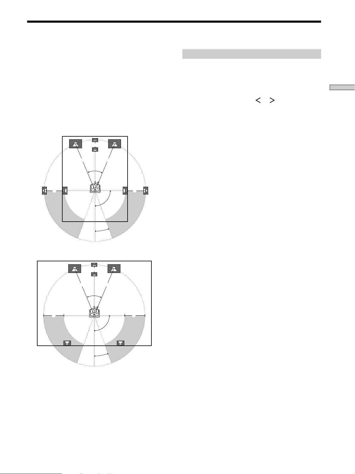
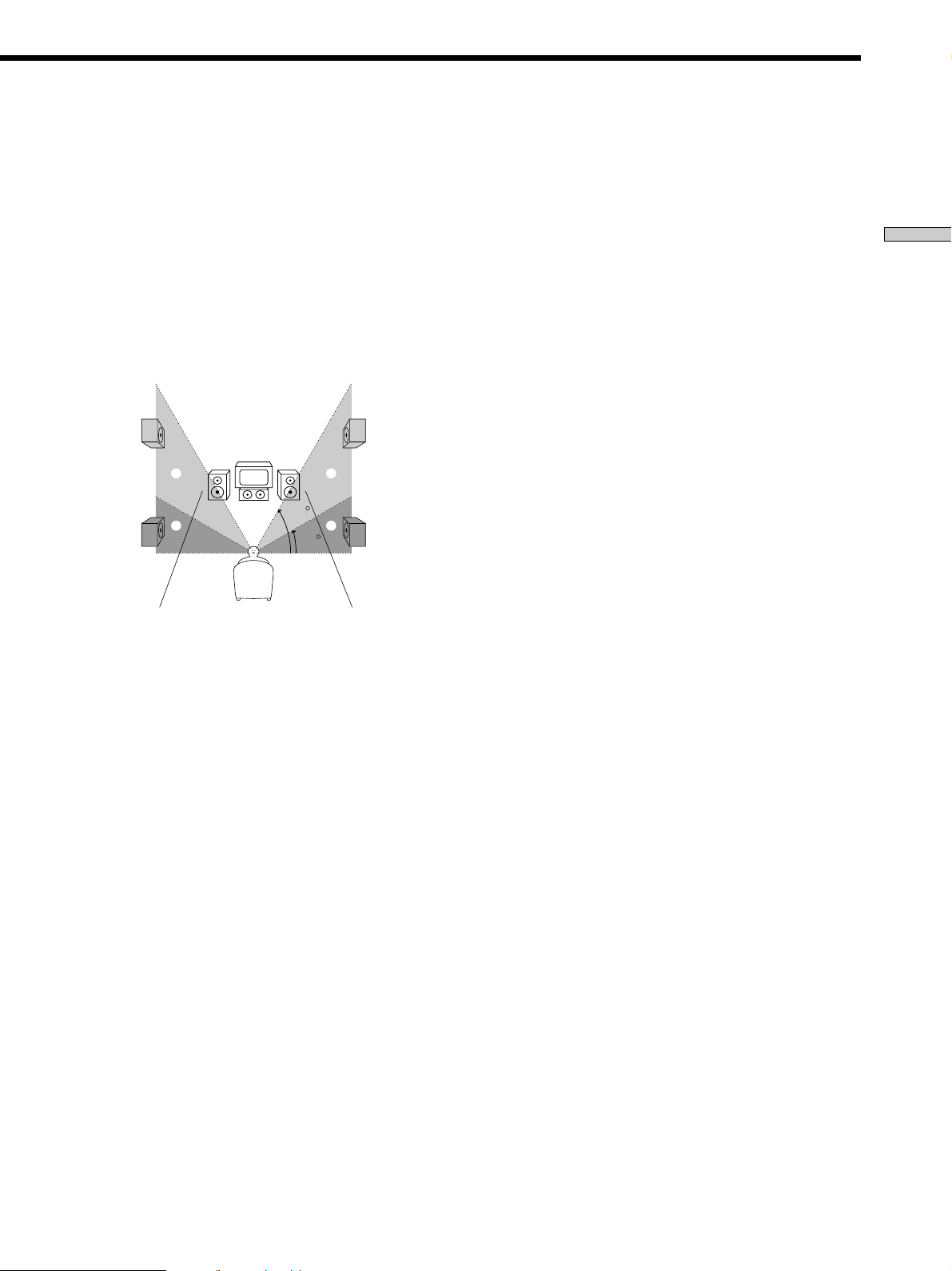
For the best possible surround sound all speakers should
be the same distance from the listening position (A).
However, this unit lets you to place the center speaker up
to 5 feet (1.5 meters) closer (B) and the rear speakers up
to 15 feet (4.5 meters) closer (C) to the listening position.
The front speakers can be placed from 3 to 40 feet (1.0 to
12.0 meters) from the listening position (A).
You can place the rear speakers either behind you or to
the side, depending on the shape of your room (etc.).
When placing rear speakers to your side
B
A A
45°
CC
90°
20°
When placing rear speakers behind you
Specifying the speaker parameters
1 Press ?/1 to turn on the receiver.
2 Press SET UP.
Hooking Up and Setting Up the Speaker System
3 Press the cursor buttons ( or ) to select the
parameter you want to adjust.
4 Turn the jog dial to select the setting you desire.
The setting is entered automatically.
5 Repeat steps 3 and 4 until you have set all of the
parameters that follow.
x Front speaker size (FRONT)
Initial setting : LARGE
• If you connect large speakers that will effectively
reproduce bass frequencies, select “LARGE”. Normally,
select “LARGE”.
• If the sound is distorted, or you feel a lack of surround
effects when using multi channel surround sound,
select “SMALL” to activate the bass redirection circuitry
and output the front channel bass frequencies from the
sub woofer.
• When the front speaker is set to “SMALL”, the center
and rear speakers are also automatically set to
“SMALL” (unless previously set to “NO”).
B
A A
45°
CC
90°
20°
Note
Do not place the center speaker farther away from the listening
position than the front speakers.
19
GB
Page 20
Multi Channel Surround Setup
x Center speaker size (CENTER)
Initial setting : LARGE
• If you connect a large speaker that will effectively
reproduce bass frequencies, select “LARGE”. Normally,
select “LARGE”. However, if the front speakers are set
Hooking Up and Setting Up the Speaker System
to “SMALL”, you cannot set the center speaker to
“LARGE”.
• If the sound is distorted, or you feel a lack of surround
effects when using multi channel surround sound,
select “SMALL” to activate the bass redirection circuitry
and output the center channel bass frequencies from the
front speakers (if set to “LARGE”) or sub woofer.*
• If you do not connect a center speaker, select “NO”. The
sound of the center channel will be output from the
front speakers.*
2
x Rear speaker size (REAR)
Initial setting : LARGE
• If you connect large speakers that will effectively
reproduce bass frequencies, select “LARGE”. Normally,
select “LARGE”. However, if the front speakers are set
to “SMALL”, you cannot set the rear speakers to
“LARGE”.
• If the sound is distorted, or you feel a lack of surround
effects when using multi channel surround sound,
select “SMALL” to activate the bass redirection circuitry
and output the rear channel bass frequencies from the
sub woofer or other “LARGE” speakers.
• If you do not connect rear speakers, select “NO”.*
z
*1~*3 correspond to the following Dolby Pro Logic modes
*1 NORMAL
*2 PHANTOM
*3 3 STEREO
z
About speaker sizes (LARGE and SMALL)
Internally, the LARGE and SMALL settings for each speaker
determine whether or not the internal sound processor will cut
the bass signal from that channel. When the bass is cut from a
channel, the bass redirection circuitry sends the corresponding
bass frequencies to the sub woofer or other “LARGE” speakers.
However, since bass sounds have a certain amount of
directionality, it best not to cut them, if possible. Therefore, even
when using small speakers, you can set them to “LARGE” if you
want to output the bass frequencies from that speaker. On the
other hand, if you are using a large speaker, but prefer not to
1
have bass frequencies output from that speaker, set it to
“SMALL”.
If the overall sound level is lower than you prefer, set all speakers
to “LARGE”. If there is not enough bass, you can use the
equalizer to boost the bass levels. To adjust the equalizer, see
page 40.
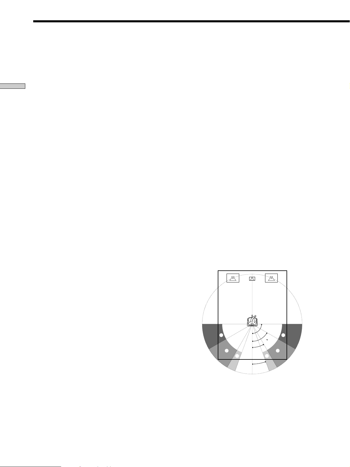
x Rear speaker position (REAR PLACE)*
Initial setting : BEHIND
This parameter lets you specify the location of your rear
speakers for proper implementation of the Digital Cinema
Sound surround modes in the “VIRTUAL” sound fields.
Refer to the illustration below.
• Select “SIDE” if the location of your rear speakers
corresponds to section A.
• Select “MIDDLE” if the location of your rear speakers
corresponds to section B.
• Select “BEHIND” if the location of your rear speakers
3
corresponds to section C.
This setting only effects the surround modes in the
“VIRTUAL” sound fields.
20
GB
A
B
90°
60°
30°
C C
20°
A
B
Page 21
x Rear speaker height (REAR HEIGHT)*
Initial setting : LOW
This parameter lets you specify the height of your rear
speakers for proper implementation of the Digital Cinema
Sound surround modes in the “VIRTUAL” sound fields.
Refer to the illustration below.
• Select “LOW” if the location of your rear speakers
corresponds to section A.
• Select “HIGH” if the location of your rear speakers
corresponds to section B.
This setting only effects the surround modes in the
“VIRTUAL” sound fields.
B
A
B
60
A
30
* These parameters are not available when “Rear speaker
size (REAR)” is set to “NO”.
z
About the rear speaker position (SIDE, MIDDLE, and BEHIND)
This setting is designed specifically for implementation of the
Digital Cinema Sound modes in the “VIRTUAL” sound fields.
With the Digital Cinema Sound modes, speaker position is not as
critical as other modes. All of the modes in the “VIRTUAL”
sound fields were designed under the premise that the rear
speaker would be located behind the listening position, but
presentation remains fairly consistent even with the rear speakers
positioned at a rather wide angle. However, if the speakers are
pointing toward the listener from the immediate left and right of
the listening position, the “VIRTUAL” sound fields will not be
effective unless the rear speaker position parameter is set to
“SIDE”.
Nevertheless, each listening environment has many variables,
like wall reflections, and you may obtain better results using
“BEHIND” or “MIDDLE” if your speakers are located high above
the listening position, even if they are to the immediate left and
right.
Therefore, although it may result in a setting contrary to the
“Rear speaker position” explanation, we recommend that you
playback multi channel surround encoded software and listen to
the effect each setting has on your listening environment. Choose
the setting that provides a good sense of spaciousness and that
best succeeds in forming a cohesive space between the surround
sound from the rear speakers and the sound of the front speakers.
If you are not sure which sounds best, select “BEHIND” and then
use the speaker distance parameter and speaker level
adjustments to obtain proper balance.
x Sub woofer selection (SUB WOOFER)
Initial setting : YES
• If you connect a sub woofer, select “YES”.
• If you do not connect a sub woofer, select “NO”. This
activates the bass redirection circuitry and outputs the
LFE signals from other speakers.
• In order to take full advantage of the Dolby Digital
(AC-3) bass redirection circuitry, we recommend setting
the sub woofer’s cut off frequency as high as possible.
x Front speaker distance (FRONT)
Initial setting : 16 feet* (5.0 meter)
Set the distance from your listening position to the front
(left or right) speaker (A on page 19).
• Front speaker distance can be set in 1 foot* (0.1 meter)
steps from 3 to 40 feet* (1.0 to 12.0 meters).
• If both speakers are not placed an equal distance from
your listening position, set the distance to the closest
speaker.
* Models of area code U, CA only.
x Center speaker distance (CENTER)
Initial setting : 16 feet* (5.0 meter)
Set the distance from your listening position to the center
speaker.
• Center speaker distance can be set in 1 foot* (0.1 meter)
steps from a distance equal to the front speaker distance
(A on page 19) to a distance 5 feet* (1.5 meters) closer to
your listening position (B on page 19).
• Do not place the center speaker farther away from your
listening position than the front speakers.
* Models of area code U, CA only.
x Rear speaker distance (REAR)
Initial setting : 11 feet* (3.5 meter)
Set the distance from your listening position to the rear
(left or right) speaker.
• Rear speaker distance can be set in 1 foot* (0.1 meter)
steps from a distance equal to the front speaker distance
(A on page 19) to a distance 15 feet* (4.5 meters) closer
to your listening position (C on page 19).
• Do not place the rear speakers farther away from your
listening position than the front speakers.
• If both speakers are not placed an equal distance from
your listening position, set the distance to the closest
speaker.
* Models of area code U, CA only.
Hooking Up and Setting Up the Speaker System
21
GB
Page 22

Multi Channel Surround Setup
z
About speaker distances
This unit allows you to input the speaker position in terms of
distance. However, it is not possible to set the center speaker
further than the front speakers. Also, the center speaker cannot be
set more that 5 feet* (1.5 meters) closer than the front speakers.
Likewise, the rear speakers cannot be set farther away from the
Hooking Up and Setting Up the Speaker System
listening position than the front speakers. And they can be no
more than 15 feet* (4.5 meters) closer.
This is because incorrect speaker placement is not conducive to
the enjoyment of surround sound.
Please note that, setting the speaker distance closer than the
actual location of the speakers will cause a delay in the output of
the sound from that speaker. In other words, the speaker will
sound like it is farther away.
For example, setting the center speaker distance 3~6 feet* (1~2 m)
closer than the actual speaker position will create a fairly realistic
sensation of being “inside” the screen. If you cannot obtain a
satisfactory surround effect because the rear speakers are too
close, setting the rear speaker distance closer (shorter) than the
actual distance will create a larger soundstage.
Adjusting these parameter while listening to the sound often
results in much better surround sound. Give it a try!
* Models of area code U, CA only.
x Distance unit (DIST. UNIT)
Initial setting : feet* (meter)
Lets you select either feet or meters as the unit of measure
for setting distances. 1 foot corresponds to a 1 ms
difference.
* Models of area code U, CA only.
x Front speaker crossover frequency
(FRONT SP >)
Initial setting : 120 Hz
Lets you adjust the front speaker bass crossover frequency
when the front speakers are set to “SMALL”. The
frequency can be adjusted in 30 Hz steps from 60 Hz to
180 Hz.
x Center speaker crossover frequency
(CENTER SP >)
Initial setting : 120 Hz
Lets you to adjust the center speaker bass crossover
frequency when the center speaker is set to “SMALL”.
The frequency can be adjusted in 30 Hz steps from 60 Hz
to 180 Hz.
Adjusting the speaker volume
Use the remote while seated in your listening position to
adjust the volume of each speaker.
Note
This unit incorporates a new test tone with a frequency centered
at 800 Hz for easier speaker volume adjustment.
1 Press ?/1 to turn on the receiver.
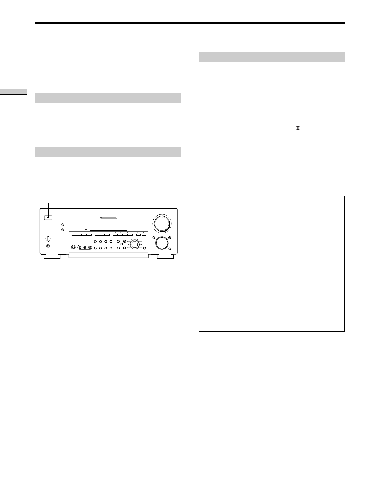
2 Press TEST TONE on the front panel (except for
models of area code CED) or on the supplied
remote.
You will hear the test tone from each speaker in
sequence.
3 Adjust the volume level so that the volume of the
test tone from each speaker sounds the same
when you are in your main listening position.
• To adjust the balance of the front right and front left
speakers, use the front balance parameter in the
LEVEL menu (see page 39).
• To adjust the balance of the rear right and rear left
speakers, use the rear balance parameter in the
LEVEL menu (see page 39).
• To adjust the volume level of the center speaker,
press the LEVEL CENTER +/– buttons on the
remote.
• To adjust the volume level of the rear speakers, press
the LEVEL REAR +/– buttons on the remote.
4 Press TEST TONE again to turn off the test tone.
Note
The test tone cannot be output when the receiver is set to 5.1CH
INPUT.
z
You can adjust the volume level of all speakers at the same
time
Rotate MASTER VOLUME on the main unit or press MASTER
VOLUME +/– on the remote.
x Rear speaker crossover frequency (REAR SP >)
Initial setting : 120 Hz
Lets you adjust the rear speaker bass crossover frequency
when the rear speakers are set to “SMALL”. The
frequency can be adjusted in 30 Hz steps from 60 Hz to
180 Hz.
GB
22
Page 23
Notes
• The front balance, rear balance, center level, and rear level are
shown in the display during adjustment.
• Although these adjustments can also be made via the front
panel using the LEVEL menu (when the test tone is output, the
receiver switches to the LEVEL menu automatically), we
recommend you follow the procedure described above and
adjust the speaker levels from your listening position using the
remote control.
Before You Use Your Receiver
Before turning on the receiver
Make sure that you have:
• Turned MASTER VOLUME to the leftmost position (0).
• Selected the appropriate front speakers (see “wj
SPEAKERS selector” on page 30).
Hooking Up and Setting Up the Speaker System
Checking the connections
After connecting all of your components to the receiver,
do the following to verify that the connections were made
correctly.
1/u
?/1
•
•
•
•
–+ –+
–
+
MASTER VOLUME
5
•
•
•
46
•
•
•
3
•
•
•
2
•
•
•
1
•
•
•
0
+
–
•
•
•
•
•
•
7
•
•
•
8
•
•
•
9
•
•
•
10
FUNCTION
1 Press ?/1 to turn on the receiver.
2 Rotate FUNCTION to select a component (program
source) that you connected (e.g., CD player or tape
deck).
3 Turn on the component and start playing it.
4 Rotate MASTER VOLUME to turn up the volume.
If you do not obtain normal sound output after
performing this procedure, look for the reason in the
checklist on the following page and take the appropriate
measures to correct the problem.
23
GB
Page 24

Before You Use Your Receiver
There is no sound no matter which component is
selected.
, Check that both the receiver and all components
are turned on.
, Check that the MASTER VOLUME control is not
Hooking Up and Setting Up the Speaker System
set at 0.
, Check that the SPEAKERS selector is not set to
OFF or to a position for front speakers that are not
connected to the receiver (see “wj SPEAKERS
selector” on page 30).
, Check that all speaker cords are connected
correctly.
, Press the MUTING button to turn off the indicator
on the button.
There’s no sound from a specific component.
, Check that the component is connected correctly to
the audio input jacks for that component.
, Check that the cord(s) used for the connection is
(are) fully inserted into the jacks on both the
receiver and the component.
No sound is heard from one of the front
speakers.
, Connect a pair of headphones to the PHONES jack
and set the SPEAKERS selector to OFF to verify
that sound is output from the headphones (see “wj
SPEAKERS selector” and “PHONES jack” on page
30).
If only one channel is output from the headphones,
the component may not be connected to the
receiver correctly. Check that all the cords are fully
inserted into the jacks on both the receiver and the
component.
If both channels are output from the headphones,
the front speaker may not be connected to the
receiver correctly. Check the connection of the front
speaker which is not outputting any sound.
If you encounter a problem that is not included above, see
“Troubleshooting” on page 56.
24
GB
Page 25

Hooking Up and Setting Up the Speaker System
25
GB
Page 26

Location of Parts and Basic Operations
This chapter provides information
about the locations and functions of
the buttons and controls on the front
panel. It also explains basic
operations.
Front Panel Parts Description
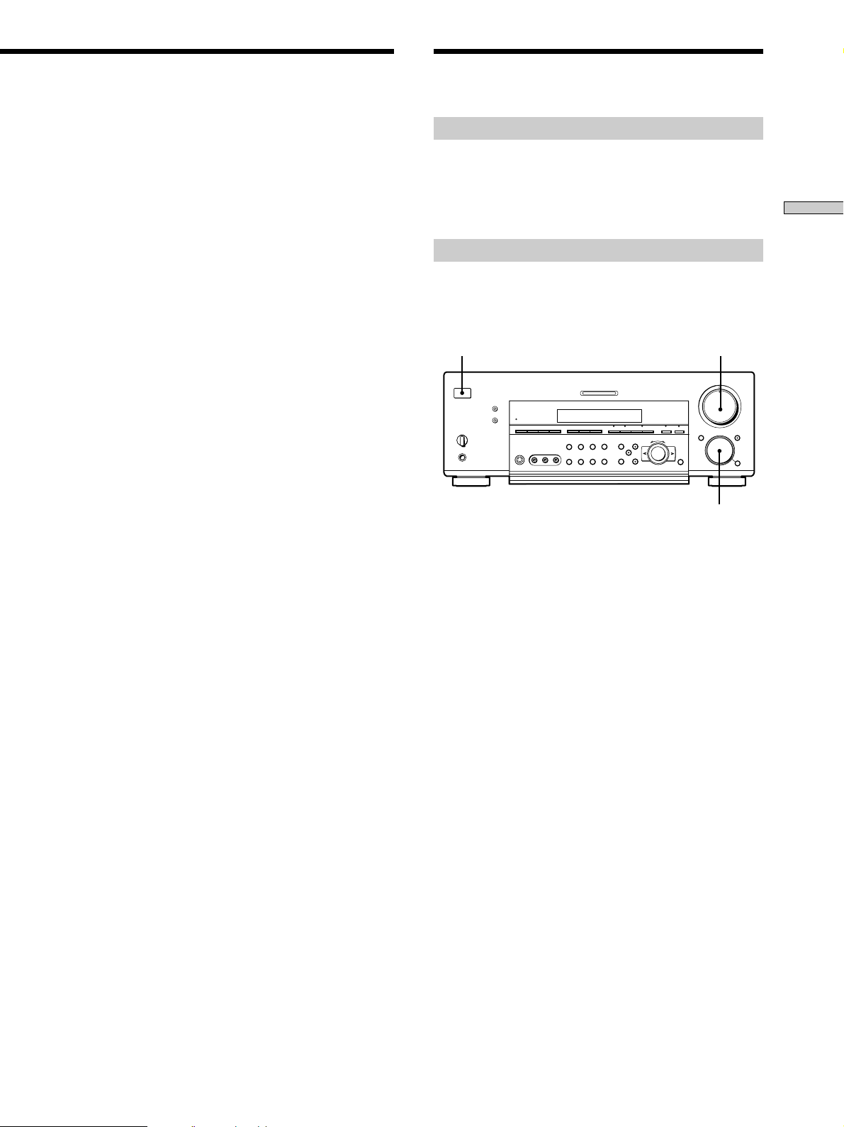
1 ?/1 switch
Press to turn the receiver on and off.
• Before you turn on the receiver, make sure that you have
turned the MASTER VOLUME control to the leftmost
position to avoid damaging your speakers.
2 MASTER VOLUME control
After turning on the component you selected, rotate to
adjust the volume.
3 MUTING button
Press to mute the sound. The indicator on the button
lights up when the sound is muted.
4 FUNCTION control
Rotate to select the component you want to use.
To select Rotate to light
VCR VIDEO 1 or VIDEO 2
Camcorder or video game VIDEO 3
DVD or LD player DVD/LD
TV or satellite tuner TV/SAT
Tape deck TAPE (STR-DB940)
MD or Tape deck MD/TAPE (STR-DB840)
MD or DAT deck MD/DAT (STR-DB940 only)
CD player CD
Built in tuner TUNER
Turntable PHONO
After selecting the component, turn on the component
you selected and play the program source.
26
• After selecting VCR, camcorder, video game, DVD player,
or LD player, turn on the TV and set the TV’s video input
to match the component you selected.
GB
Page 27
SPEAKERS
OFF
+B
A
1
?/1
•
•
PHONES
2
MASTER VOLUME
5
•
•
•
•
•
•
46
MULTI CHANNEL DECODING
DIMMER
DISPLAY
A
B
•
•
BASS BOOST
VIDEO 3 INPUT
MEMORY
FM MODE
CINEMA STUDIO EX.
–
MODE–+SHIFT A B A.F.D.
SET UP
NAME
LEVEL
SUR
EQ
+
–
ENTER
+
EQUALIZER
INPUT
MODE
PRESET
– + C 2 CH ANLG DIRECT 5.1CH INPUTFM/AM
TUNING
RLVIDEOS-VIDEO AUDIO
•
•
•
3
•
•
•
2
•
•
•
1
•
•
•
0
DOOR OPEN FUNCTION MUTING
•
•
•
•
10
MODE
•
7
•
•
•
8
•
•
•
9
•
Location of Parts and Basic Amplifier Operations
345
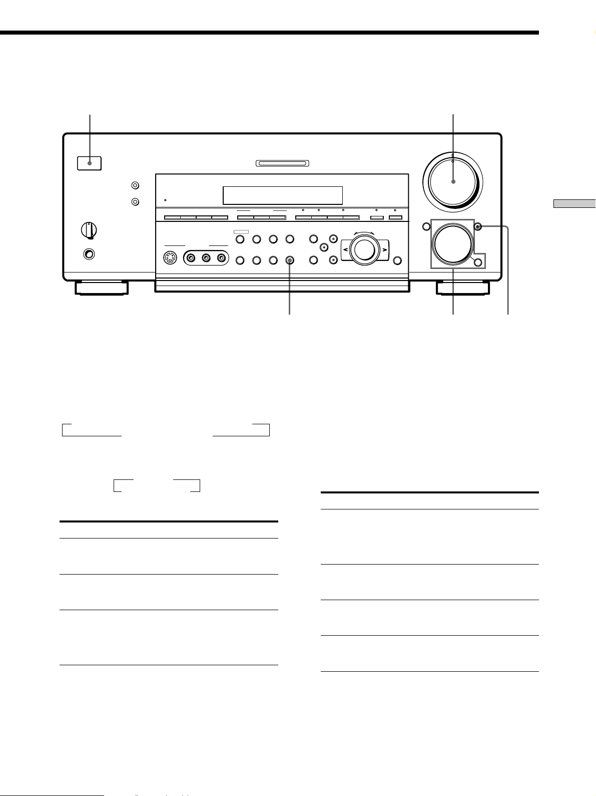
MODE button
Press to select and play another video/audio source in
combination with the selected component.
Each time you press the button, the display changes as
follows:
Standard display (When 5.1CH INPUT is not selected)
t V:XXX t A:XXX t 2ND AUDIO [XXX]*
selected component T
When 5.1CH INPUT is selected
t V:XXX
5.1CH INPUT T
* STR-DB940 only.
Press MODE to display And rotate FUNCTION to select
V:XXX Any video source to enjoy with
the audio from the selected
component
A:XXX Any audio source to enjoy with
the video from the selected
component
2ND AUDIO [XXX] An audio source (except
(STR-DB940 only) PHONO) to enjoy in your sub
room. “SOURCE” selects the
same program source as the main
FUNCTION control**
** Even if 2ND AUDIO [SOURCE] is selected, no sound is output
when the receiver is set to 5.1CH INPUT. Only signals from
components connected to the analog inputs are output through
the 2ND AUDIO jacks. No signals are output from components
connected to only the digital inputs.
z Function indicators
Normally, the indicator above the selected function lights orange.
However, when MODE is used to select a different video (V:XXX)
or audio (A:XXX) source, the video function lights green and the
audio function lights orange. This also occurs when you select
audio components (like CD).
5 INPUT MODE button
Press to select the input mode for your digital
components (DVD/LD, TV/SAT, and MD/DAT
(STR-DB940) or MD/TAPE (STR-DB840)).
Each press switches the input mode of the currently
selected component.
Select To
AUTO Give priority to digital signals
when there are both digital and
analog connections. If there are
no digital signals, analog is
selected
DIGITAL (OPTICAL) Specify the digital audio signals
input to the DIGITAL OPTICAL
input jacks
DIGITAL (COAXIAL) Specify the digital audio signals
input to the DIGITAL COAXIAL
input jacks (DVD/LD only)
ANALOG Specify the analog audio signals
input to the AUDIO IN (L and R)
jacks
27
GB
Page 28
Front Panel Parts Description
7
6
?/1
DIMMER
DISPLAY
SPEAKERS
A
B
OFF
Location of Parts and Basic Amplifier Operations
•
•
•
+
B
A
•
PHONES
BASS BOOST
8
VIDEO 3 INPUT
PRESET
– + C 2 CH ANLG DIRECT 5.1CH INPUTFM/AM
TUNING
RLVIDEOS-VIDEO AUDIO
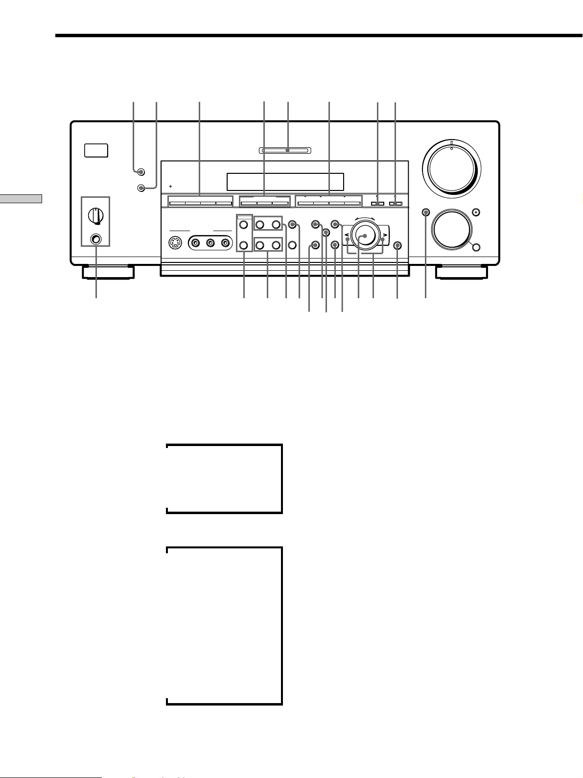
6 DIMMER button
Press repeatedly to adjust the brightness of the display.
When you want to turn off the display, set in the
“DIMM. RANGE” parameter in the SET UP menu
(page 54).
MEMORY
FM MODE
whwj
9
MULTI CHANNEL DECODING
CINEMA STUDIO EX.
–
+
wg
q; qa
SET UP
EQUALIZER
INPUT
MODE
wdwf
SUR
NAME
ql
wa
ws
w;
* Index name appears only when you have assigned one to the
** These indications appear only during RDS reception. (Models of
qs
qd
MASTER VOLUME
5
•
•
•
•
•
•
LEVEL
46
•
•
•
3
•
•
•
2
•
•
•
1
•
•
•
MODE–+SHIFT A B A.F.D.
+
–
EQ
qj
ENTER
qh
0
DOOR OPEN FUNCTION MUTING
qfqg
•
•
•
10
MODE
•
7
•
•
•
8
•
•
•
9
•
•
qk
component or preset station (see page 51). Index name does not
appear when only blank spaces have been entered, or it is the
same as the function button.
area code CED only. See page 47.)
7 DISPLAY button
Press repeatedly to change the information on the
display window as follows:
Index name of the component
Sound field applied to the program source
v
v
Selected component
v
When the tuner is selected
Index name of the preset station*
v
or program station name**
v
Frequency
v
Program type indication**
v
Radio text**
v
Current time**
v
Sound field applied to the band
or the preset station
8 The following buttons operate the built-in tuner. For
details, see “Receiving Broadcasts” starting from page
43.
FM/AM button
Selects the FM or AM band.
SHIFT button
Selects a memory page for preset stations.
PRESET TUNING +/– buttons
Scans all preset stations.
9 CINEMA STUDIO EX. A~C buttons
Press to select CINEMA STUDIO EX. A~C sound field.
For details, see “CINEMA STUDIO EX. A~C” on page
33.
0 MULTI CHANNEL DECODING indicator
This indicator lights when the unit is decoding signals
recorded in a multi channel format.
28
GB
Page 29

qa Use these buttons to enjoy surround sound. For
details, see “Enjoying Surround Sound” starting from
page 31.
A.F.D. button / indicator
Press to set the receiver to automatically detect the
type of audio signal being input and perform proper
decoding (if necessary). For details, see “AUTO
FORMAT DECODING” on page 35.
2CH button / indicator
Press to output sound from only the front (left and
right) speakers. For details, see “2 CHANNEL” on
page 35.
MODE +/– buttons / indicator
Press repeatedly to select the sound field you desire.
For details, see “Selecting a Sound Field” on page 32.
• Sound fields are not compatible with 96 kHz digital audio
signals.
qs ANLG DIRECT button
Press to listen to an analog source without digital
processing by the equalizer, sound field, etc.
For details, see “ANALOG DIRECT” on page 35.
qd 5.1CH INPUT button
Press to enjoy the audio source connected to the 5.1CH
INPUT jacks. Press 5.1 CH again to return to the
original function.
• When 5.1CH INPUT is selected, the equalizer, bass boost,
and sound field effects do not function.
qf DOOR OPEN button
Press to open the door on the front panel.
qg ENTER button
Press to enter individual characters for the preset
station and program source names.
qh Cursor buttons (
/ )
Press to select various speaker level, surround, and
equalizer parameters (etc.).
qj Jog dial
Turn to adjust the selected speaker level, surround,
and equalizer parameters (etc.).
qk LEVEL button
Press to activate the speaker level parameters (page
39). The indicator on the button lights up and you can
adjust the various speaker level parameters (front
balance, rear balance, etc.).
ql EQ button
Press to activate the equalizer parameters (page 40).
The indicator on the button lights up and you can
adjust the various equalizer parameters.
Location of Parts and Basic Amplifier Operations
w; SUR button
Press to activate the surround parameters (page 38).
The indicator on the button lights up and you can
adjust the various surround parameters (effect level,
wall type, etc.).
wa SET UP button
Press to activate the setup mode, then use the cursor
buttons (qh) to select any of the following parameters.
You can make various settings using the jog dial (qj).
When you select You can
Speaker setup Specify the front, center, rear speaker
sizes, the rear speaker position, and
whether or not you are using a sub
woofer (page 19).
Speaker Distance Specify the front, center, and rear speaker
distances and the unit of measurement
(page 21).
Crossover Specify the front, center, and rear speaker
frequency* bass crossover frequency (page 22).
Auto Function Specify whether or not Sony components
connected via Control A1 cords will turn
on or off when selected using the
function buttons (page 53).
2 way remote Turn on or off response to remote
(STR-DB940 only) signals sent from the 2 way remote (page
53).
Color system Select the TV color system of the monitor.
(STR-DB940 of area
codes other than
U, CA)
OSD color Specify the color of the on-screen
(STR-DB940 only) display (page 54).
Dimmer Range Specify the display to turn off when you
press the DIMMER button several times
(page 54).
* Only when the speaker is set to“SMALL” in the speaker setup
parameter.
29
GB
Page 30

Front Panel Parts Description
ws NAME button
Press to activate the name function and enter names
for preset stations and program sources (page 51).
wd EQUALIZER button
Press to turn the equalizer on or off. The EQ indicator
in the display lights in the display when the equalizer
is turned on.
When you adjust the equalizer using the EQ
parameters (page 40), the settings are stored
Location of Parts and Basic Amplifier Operations
automatically and can be reproduced whenever you
turn on the equalizer.
• The equalizer is not compatible with 96 kHz digital audio
signals and during 5.1CH input.
wf The following buttons operate the built-in tuner. For
details, see “Receiving Broadcasts” starting from page
43.
Models of area code CED
TUNING/PTY SELECT +/– buttons
Scans all the available radio stations.
Selects program types during PTY operations.
Models of other area codes
TUNING +/– buttons
Scans all the available radio stations.
wh The following buttons operate the built-in tuner. For
details, see “Receiving Broadcasts” starting from page
43.
MEMORY button
Press to memorize a preset station.
FM MODE button
If “STEREO” flashes in the display and the FM stereo
reception is poor, press this button. You will not have
the stereo effect but the sound is improved.
wj SPEAKERS selector
Set according to the front speakers you want to drive.
Set to To select
A The speakers connected to the FRONT
B The speakers connected to the FRONT
A+B* The speakers connected to both the FRONT
OFF No speaker output
Be sure to connect front speakers with a nominal impedance of
*
8 ohms or higher if you want to select both sets (A+B) of front
speakers. In this case, set the IMPEDANCE SELECTOR to
“4Ω”.
SPEAKERS A terminals
SPEAKERS B terminals
SPEAKERS A and B terminals (parallel
connection)
wg
Models of area code CED
The following buttons operate the built-in tuner.
For details, see “Using the Radio Data System
(RDS)” starting from page 47.
RDS EON button
Press to set the receiver to automatically switch to
stations broadcasting traffic announcements, news,
or information program. The EON button does not
function during AM reception.
RDS PTY button
Press to scan stations by program type. The PTY
button does not function during AM reception.
Models of other area codes
TEST TONE button
Press to output the test tone.
SLEEP button
Press to activate the sleep timer.
PHONES jack
Connects headphones.
• To use the headphones, set the SPEAKERS selector to OFF
to output sound to the headphones.
• To enjoy surround sound from the headphones, we
recommend selecting the HEADPHONE THEATER sound
field. Selecting other sound fields when the SPEAKERS
selector is set to OFF automatically presents a 2 channel
(stereo) downmix from the headphones.
30
GB
Page 31

Enjoying Surround Sound
This chapter describes how to set up
the receiver to enjoy surround sound.
You can enjoy multi channel surround
when playing back software encoded
with Dolby Digital or DTS.
You can take advantage of surround sound simply by
selecting one of the receiver’s pre-programmed sound
modes. They bring the exciting and powerful sound of
movie theaters and concert halls into your home. You can
also customize the sound modes to obtain the sound you
desire by changing the various surround parameters.
The receiver contains a variety of different sound modes.
The cinema sound modes are designed for use when
playing back movie software (DVD, LD, etc.) encoded
with multi channel surround sound or Dolby Pro Logic.
In addition to decoding the surround sound, some of
these modes also provide sound effects commonly found
in movie theaters.
The virtual sound modes contain compelling applications
of the Sony Digital Cinema Sound digital signal
processing technology. They shift the sound away from
the actual speaker locations to simulate the presence of
several “virtual” speakers.
The music (etc.) sound modes are designed for use with
standard audio sources and TV broadcasts. They add
reverberation to the source signal to make you feel as if
you were in a concert hall or stadium (etc.). Use these
sound modes with two-channel sources like CD and
stereo broadcasts of sports programs or musical concerts.
For more information about the sound modes, see pages
33~35.
Enjoying Surround Sound
A.F.D.
The “Auto Format Decoding” sound mode presents the
sound exactly as it was encoded, without adding any
reverberation (etc.).
To fully enjoy surround sound, you must register the
number and location of you speakers. See “Multi Channel
Surround setup” starting on page 19 to set the speaker
parameters before enjoying surround sound.
31
GB
Page 32

Sound field buttons
?/1
•
•
•
•
–+ –+
EQUALIZER
CINEMA STUDIO EX. A~C
–
+
SUR
Cursor buttons
ANLG DIRECT
+
–
Jog dial
EQ
LEVEL
•
•
•
46
•
•
•
3
•
•
•
2
•
•
•
1
•
•
•
0
Selecting a Sound Field
5
•
•
•
•
•
•
7
•
•
•
8
•
•
•
9
•
•
•
10
You can enjoy surround sound simply by selecting one of
the pre-programmed sound fields according to the
program you want to listen to.
1 Press MODE +/– repeatedly to select the sound
field you desire.
The current sound field is indicated in the display.
See the table starting on page 33 for information on
each sound field.
Brief descriptions of buttons used to
enjoy surround sound
LEVEL button: Press to light and customize the level
Enjoying Surround Sound
parameters.
SUR button: Press to light and customize the surround
parameters in the current sound field.
EQ button: Press to light and customize the equalizer
parameters in the current sound field.
Cursor buttons ( / ): Use to select parameters after
pressing the LEVEL, SUR, or EQ buttons.
Jog dial: Use to adjust parameters and select sound fields
(etc.).
A.F.D. button: Press to set the receiver to automatically
detect the type of audio signal being input and perform
proper decoding (if necessary).
2CH button: Press to output sound from only the front
(left and right) speakers.
To turn the sound field off
Press A.F.D. or 2CH (page 35).
z
The receiver memorizes the last sound field selected for each
program source (Sound Field Link)
Whenever you select a program source, the sound field that was
last applied is automatically applied again. For example, if you
listen to CD with STADIUM as the sound field, change to a
different program source, then return to CD, STADIUM will be
applied again. With the tuner, sound fields are memorized
separately for AM, FM, and all preset stations.
z
You can identify the encoding format of program software
by looking at its packaging
Dolby Digital discs are labeled with the logo, and Dolby
Surround encoded programs are labeled with the A
logo.
MODE +/– buttons: Press to select the sound field.
CINEMA STUDIO EX. A~C buttons: Press to select
CINEMA STUDIO EX. A~C sound field.
EQUALIZER button: Turns the equalizer on or off.
ANLG DIRECT button: Press to input the analog signal
without digital processing. When this function is on, the
equalizer, bass boost and sound field (etc.) are turned off.
GB
32
Page 33

Sound field Effect Notes
NORMAL SURROUND
CINEMA STUDIO EX. A
1)2)
(Press CINEMA STUDIO EX. A
button)
CINEMA STUDIO EX. B
1)2)
(Press CINEMA STUDIO EX. B
button)
CINEMA STUDIO EX. C
1)2)
(Press CINEMA STUDIO EX. C
button)
SEMI CINEMA STUDIO EX. A
SEMI CINEMA STUDIO EX. B
SEMI CINEMA STUDIO EX. C
Software with multi channel surround audio signals is
played according to the way it was recorded.
Software with 2 channel audio signals, is decoded with
Dolby Pro Logic to create surround effects.
Reproduces the sound characteristics of the Sony
Pictures Entertainment “Cary Grant Theater” cinema
production studio using the 3D sound imaging of
V. MULTI DIMENSION (page 34) to create 5 sets of
virtual speakers surrounding the listener from a single
pair of actual rear speakers.
Reproduces the sound characteristics of the Sony
Pictures Entertainment “Kim Novak Theater” cinema
production studio using the 3D sound imaging of
V. MULTI DIMENSION (page 34) to create 5 sets of
virtual speakers surrounding the listener from a single
pair of actual rear speakers.
Reproduces the sound characteristics of the Sony
Pictures Entertainment scoring stage using the 3D
sound imaging of V. MULTI DIMENSION (page 34) to
create 5 sets of virtual speakers surrounding the listener
from a single pair of actual rear speakers.
1)
Reproduces the sound characteristics of the Sony
Pictures Entertainment “Cary Grant Theater” cinema
production studio using the 3D sound imaging of
V. SEMI-M. DIMENSION (page 34) to create 5 sets of
virtual speakers surrounding the listener from the
sound of the front speakers (without using actual rear
speakers).
1)
Reproduces the sound characteristics of the Sony
Pictures Entertainment “Kim Novak Theater” cinema
production studio using the 3D sound imaging of
V. SEMI-M. DIMENSION (page 34) to create 5 sets of
virtual speakers surrounding the listener from the
sound of the front speakers (without using actual rear
speakers).
1)
Reproduces the sound characteristics of the Sony
Pictures Entertainment scoring stage using the 3D
sound imaging of V. SEMI-M. DIMENSION (page 34) to
create 5 sets of virtual speakers surrounding the listener
from the sound of the front speakers (without using
actual rear speakers).
This is a standard mode, great for
watching most any type of movie.
This mode is ideal for watching sciencefiction or action movies with lots of sound
effects.
This mode is ideal for watching musicals
or classic films where music is featured in
the soundtrack.
LCR
RSLS
LS
RS
RSLS
Enjoying Surround Sound
NIGHT THEA TER
Allows you to retain a theater like environment while
listening at low volume levels, such as late at night.
MONO MOVIE
Creates a theater like environment from movies with
monaural soundtracks.
STEREO MOVIE
Creates a theater like environment from movies
recorded with stereo soundtracks.
HEADPHONE THEATER
Allows you to experience a theater like environment
while listening through a pair of headphones.
1)
“VIRTUAL” sound field: Sound field with virtual speakers.
Very effective with 5.1ch discreet signal
sources like Dolby Digital and DTS.
However, turning the SUR menu “VIR. SPEAKERS” parameter off when using “CINEMA STUDIO EX. A~C” or “SEMI CINEMA
STUDIO EX. A~C” reproduces the sound characteristics of each cinema production studio without virtual speakers.
2)
You can select directly by pressing the buttons on the front panel.
33
GB
Page 34

Selecting a Sound Field
Sound field Effect Notes
V. MULTI DIMENSION
1)
(Virtual Multi Dimension)
Uses 3D sound imaging to create an array of virtual rear
speakers positioned higher than the listener from a
single pair of actual rear speakers. This mode creates 5
sets of virtual speakers surrounding the listener at
approximately a 30° angle of elevation.
SIDE*
MIDDLE*
LCR
RSLS
LS
LCR
RS
RSLS
RSLS
Enjoying Surround Sound
V. MULTI REAR
(Virtual Multi Rear)
LS
LCR
RS
RSLS
BEHIND*
RSLS
LS
1)
Uses 3D sound imaging to create 3 sets of virtual rear
speakers from 1 set of actual rear speakers.
SIDE*
LCR
LS
LCR
RS
RSLS
* See
page 20
RSLS
RS
RSLS
MIDDLE*
RSLS
LS
LCR
RS
RSLS
BEHIND*
RSLS
V. SEMI-M. DIMENSION
1)
(Virtual Semi Multi Dimension)
Uses 3D sound imaging to create virtual rear speakers
from the sound of the front speakers without using
actual rear speakers. This mode creates 5 sets of virtual
speakers surrounding the listener at a 30° angle of
elevation.
1)
“VIRTUAL” sound field: Sound field with virtual speakers.
GB
34
LS
LCR
LS
RS
RSLS
* See
RSLS
RS
RSLS
page 20
Page 35

Sound field Effect Notes
VIRTUAL ENHANCED A
1)
(Virtual Enhanced Surround A)
Uses 3D sound imaging to create 3 sets of virtual rear
speakers from the sound of the front speakers without
using actual rear speakers.
LCR
RSLS
VIRTUAL ENHANCED B
1)
(Virtual Enhanced Surround B)
SMALL HALL
LARGE HALL
Uses 3D sound imaging to create 1 set of virtual rear
speakers from the sound of the front speakers without
using actual rear speakers.
Reproduces the acoustics of a small rectangular concert
hall.
Reproduces the acoustics of a large rectangular concert
Ideal for soft acoustic sounds.
LCR
RSLS
LS
RS
RSLS
hall.
OPERA HOUSE
JAZZ CLUB
DISCO/CLUB
CHURCH
LIVE HOUSE
ARENA
STADIUM
GAME
Reproduces the acoustics of an opera house.
Reproduces the acoustics of a jazz club.
Reproduces the acoustics of a discotheque/dance club.
Reproduces the acoustics of a stone church.
Reproduces the acoustics of a 300-seat live house.
Reproduces the acoustics of a 1000-seat concert hall.
Reproduces the feeling of a large open-air stadium.
Obtains maximum audio impact from video game
software.
1)
“VIRTUAL” sound field: Sound field with virtual speakers.
Ideal for musicals and opera.
Great for rock or pop music.
Great for sporting events or electric
(amplified) music.
Be sure to set the game machine to stereo
mode when using game software with
stereo sound capabilities.
Notes
• The effects provided by the virtual speakers may cause increased noise in the playback signal.
• When listening to sound fields that employ the virtual speakers, you will not be able to hear any sound coming directly from the rear
speakers.
Enjoying Surround Sound
Use the buttons on the front panel to operate the following modes
AUTO FORMAT DECODING
(Press the A.F.D. button)
2 CHANNEL
(Press the 2CH button)
ANALOG DIRECT
(Press the ANLG DIRECT
button)
Automatically detects the type of audio signal being
input (Dolby Digital, DTS, Dolby Pro Logic, or standard
2 channel stereo) and performs the proper decoding if
necessary. This mode presents the sound as it was
recorded/encoded, without adding any effects.
Outputs the sound from the front left and right speakers
only. Standard two channel (stereo) sources completely
bypass the sound field processing. Multi channel surround
formats are downmixed to two channels.
The analog input signal is not digitally processed. Only
volume control and the balance between the front left
and front right speakers can be adjusted.
You can use this mode as a reference. Set
the equalizer to OFF while using this mode
to hear the source sound exactly as it was
recorded.
This allows you to play any source using
only the front left and right speakers.
This mode is suitable for the enjoyment of
high quality analog audio sources.
Note
No sound is output from the sub woofer when the 2 CHANNEL mode is selected. To listen to two channel (stereo) sources using the front
left and right speakers and a sub woofer, use the AUTO FORMAT DECODING mode.
35
GB
Page 36

Understanding the Multi-Channel Surround Displays
123 456 7
1 OPTICAL
2 COAXIAL
Enjoying Surround Sound
3 ; DIGITAL
4 Playback channel indicators
5 L.F.E.
OPTICAL COAXIAL
MPEGDTSDUAL
DIGITAL
a
PRO LOGIC
qa 0 9 8
Lights up when the source signal is a digital signal
being input through the OPTICAL terminal.
Lights up when the source signal is a digital signal
being input through the COAXIAL terminal.
This indicator lights when a sound field other than
2 CHANNEL is selected and the unit is decoding
signals recorded in the Dolby Digital (AC-3) format.*
* However, this indicator does not light when the recording format
is 2/0 or 2/0 Pro Logic.
The letters light to indicate the channels being played
back.
L: Front Left R: Front Right
C: Center (monaural) LS: Left Surround
RS: Right Surround
S: Surround (monaural or the rear components
obtained by Pro Logic processing)
The boxes around the letters light to indicate the
speakers used to playback the channels.
See the next page for details regarding the playback
channel indicators.
The letters “L.F.E.” light up when the disc being
played contains the LFE (Low Frequency Effect)
channel. When the sound of the LFE channel signal is
actually being reproduced, the bars underneath the
letters lights up to indicate the level. Since the LFE
signal is not recorded in all parts of the input signal
the bar indication will fluctuate (and may turn off)
during playback.
L.F.E.LLSCSR
RS
6 S.WOOFER
Lights when sub woofer selection is set to “YES” and
this unit detects that the disc being played does not
contain the LFE channel signal. While this indicator is
lit, this unit creates a sub woofer signal based on the
low frequency components of the front channels.
7 Tuner indicators
These indicators light when using the receiver to tune
in radio stations, etc. See pages 43~49 for tuner
operations.
8 D. RANGE
Lights when dynamic range compression is active. See
page 40 to adjust the dynamic range compression.
9 PRO LOGIC
Lights when this unit applies Pro Logic processing to
two channel signals in order to output the center and
surround channel signals.*
* However, this indicator does not light if the center and rear
0 DTS
Lights up when DTS signals are input.
Note
When playing a DTS format disc, be sure that you have made
digital connections and that INPUT MODE is NOT set to
ANALOG (see 5 on page 27).
qa ;
Lights when Dolby Digital (AC-3) signals are input.
S.WOOFER STEREO RDS
D.RANGE EQ MONO TA NEWS INFO
speakers are set to “NO” and the A.F.D. or NORMAL
SURROUND sound fields are selected.
MEMORY
36
GB
Page 37

Source sound displays
The letters (L, C, R, etc.) indicate the source sound. The boxes around the letters vary to show how the receiver downmixes
the source sound (based on the speakers settings). When using music sound modes like LARGE HALL or SMALL HALL
the receiver adds reverberation based on the source sound.
The following table shows how the indicators light when using AUTO FORMAT DECODING mode.
Although the table below shows almost all of the configurations available from multi channel surround signals, the ones
marked “
” are the most common.
Recording
Format
(Front/Rear)
1/0
2/0*
3/0
2/1
3/1
2/2
3/2
2/0**
Input Channel Display
DOLBY DIGITAL [1/0]
dts [1/0]
DOLBY DIGITAL [2/0]
dts [2/0]
DOLBY DIGITAL [3/0]
dts [3/0]
DOLBY DIGITAL [2/1]
dts [2/1]
DOLBY DIGITAL [3/1]
dts [3/1]
DOLBY DIGITAL [2/2]
dts [2/2]
DOLBY DIGITAL [3/2]
dts [3/2]
DOLBY DIGITAL [2/0]
All speakers
present
DIGITALaC
DTS
DTS
DIGITALaL C R
DTS
DIGITALaLSR
DTS
DIGITALaL CSR
DTS
DIGITALaLLSR
DTS
DIGITALaLLSC R
DTS
PRO LOGIC
Source Sound and Output Channel Display
Rear speakers
absent
DIGITALaC
C
DTS
L R L R L R L R
R
L
C R
L
L
S
CSR
L
L
LS
C R
L
LS
L CSR
R
RS
R
RS
RS
RS
DTS
DTS
DTS
DTS
DTS
DTS
PRO LOGIC
L
DIGITALaL C R
L
DIGITALaL
L
DIGITALaL CSR
L
DIGITALaLLSR
L
LS
DIGITALaLLSC R
L
LS
L CSR
C
C R
S
S
CSR
C R
R
R
R
RS
R
RS
RS
RS
Center speaker
absent
DIGITALaC
DTS
DTS
DTS
DTS
DTS
DTS
DTS
PRO LOGIC
L
DIGITALaL CR
L
DIGITALaLSR
L
DIGITALaL CSR
L
DIGITALaLLSR
L
LS
DIGITALaLLSCR
L
LS
L CSR
speakers absent
C
DTS
R
DTS
CR
DTS
R
S
DTS
CSR
DTS
RS
R
RS
DTS
RS
CR
RS
DTS
PRO LOGIC
Rear/center
DIGITALaC
C
L
DIGITALaL CR
CR
L
DIGITALaL
DIGITALaL CSR
DIGITALaLLSR
DIGITALaLLSCR
S
L
S
CSR
L
L
LS
CR
L
LS
L CSR
Enjoying Surround Sound
R
R
R
RS
R
RS
RS
RS
DOLBY PROLOGIC
PCM XX kHz***
PRO LOGIC
L CSR
L R L R L R L R
PRO LOGIC
L CSR
PRO LOGIC
L CSR
PRO LOGIC
L CSR
* Signals with Dolby surround encoded flag OFF
** Signals with Dolby surround encoded flag ON
*** Sampling frequency is displayed
Notes
• The receiver performs Pro Logic decoding and the display conforms to 2/0** when using the following movie sound modes with 2/0* or
STEREO PCM format signals. (CINEMA STUDIO EX. A, B, C, SEMI CINEMA STUDIO EX. A, B, C, NIGHT THEATER, V. MULTI
DIMENSION, V. MULTI REAR, V. SEMI-M. DIMENSION, VIRTUAL ENHANCED A, or VIRTUAL ENHANCED B)
• When using music sound modes like LARGE HALL or SMALL HALL with standard audio formats, like PCM, the receiver creates rear
signals from the front L and R signals. In this case, sound is output from the rear speakers, but output channel indicators for the rear
speakers do not light.
37
GB
Page 38

Customizing Sound Fields
By adjusting the surround parameters and the
equalization of the front, rear and center speakers, you
can customize the sound fields to suit your particular
listening situation.
Once you customize a sound field, the changes are stored
in the memory indefinitely (unless the receiver is
unplugged for about two weeks). You can change a
customized sound field any time by making new
adjustments to the parameters.
See the table on page 41 for the parameters available in
each sound field.
Enjoying Surround Sound
To get the most from multi channel
surround sound
Position your speakers and do the procedures described
in “Multi Channel Surround Setup” starting from page 19
before you customize a sound field.
Adjusting the surround parameters
The SUR menu contains parameters that let you
customize various aspects of the current sound field. The
settings available in this menu are stored individually for
each sound field.
1 Start playing a program source encoded with multi
2 Press SUR.
channel surround sound.
The button lights up and the first parameter is
displayed.
Wall type (WALL)
Initial setting : midpoint
When sound is reflected off soft material, such as a
curtain, the high frequency elements are reduced. A hard
wall is highly reflective and does not significantly effect
the frequency response of the reflected sound. This
parameter lets you control the level of the high
frequencies to alter the sonic character of your listening
environment by simulating a softer (S) or harder (H) wall.
The midpoint designates a neutral wall (made of wood).
Reverberation (REVERB)
Initial setting : midpoint
Before sound reaches our ears, it is reflected
(reverberated) many times between he left and right
walls, ceiling, and floor. In a large room, sound takes more
time to bounce from one surface to another than in a
smaller room. This parameter lets you control the spacing
of the early reflections to simulate a sonically longer (L) or
shorter (S) room.
• The reverberation can be adjusted ±8 from S (short, –8)
to L (long, +8) in 17 steps.
• The midpoint (0) designates a standard room with no
adjustment.
Screen depth (SCREEN DEPTH)
Initial setting : MID
In a movie theater, sound seems to come from inside the
image reflected on the movie screen. This parameter
allows you to create the same sensation in your listening
room by shifting the sound of the front speakers “into”
the screen.
• The screen depth can be set to OFF, MID, or DEEP.
• DEEP provides the greatest amount of screen depth.
3 Press the cursor buttons ( or ) to select the
parameter you want to adjust.
4 Turn the jog dial to select the setting you desire.
The setting is entered automatically.
Effect level (EFFECT)
Initial setting : (depends on sound mode)
This parameter lets you adjust the “presence” of the
current surround effect.
GB
38
Virtual speaker (VIR. SPEAKERS)
Initial setting : ON
Allows you turn the virtual speakers created by the
CINEMA STUDIO EX. A, B, C and SEMI CINEMA
STUDIO EX. A, B, C sound fields off or on.
Page 39

Adjusting the level parameters
The LEVEL menu contains parameters that let you adjust
the balance and speaker volumes of each speaker. The
settings available in this menu are applied to all sound
fields.
Center level (CENTER)
Initial setting : 0 dB
Lets you adjust the level of the center speaker. The level
can even be adjusted during 5.1CH input.
• The level can be adjusted in 1 dB steps from –10 dB to
+10 dB.
1 Start playing a program source encoded with multi
channel surround sound.
2 Press LEVEL.
The button lights up and the first parameter is
displayed.
3 Press the cursor buttons ( or ) to select the
parameter you want to adjust.
4 Turn the jog dial to select the setting you desire.
The setting is entered automatically.
Front balance (FRONT)
Initial setting : center
Lets you adjust the balance between the front left and
right speakers. The level can even be adjusted during
5.1CH input.
• The balance can be adjusted ±8 dB in 1 dB steps.
• This settings can also be adjusted using the supplied
remote. See “Adjusting the speaker volume” (page 22).
Rear balance (REAR)
Initial setting : center
Lets you adjust the balance between the rear left and right
speakers. The level can even be adjusted during 5.1CH
input.
• The balance can be adjusted ±8 dB in 1 dB steps.
However, during 5.1CH input, the balance can be
adjusted ±4 dB in 1 dB steps.
• This settings can also be adjusted using the supplied
remote. See “Adjusting the speaker volume” (page 22).
Rear level (REAR)
Initial setting : 0 dB
Lets you adjust level of the rear (left and right) speakers.
The level can even be adjusted during 5.1CH input.
• The level can be adjusted in 1 dB steps from –10 dB to
+10 dB. However, during 5.1CH input, the level can be
adjusted in 1 dB steps from –6 dB to +10 dB steps.
• This settings can also be adjusted directly using the
supplied remote. See “Adjusting the speaker volume”
(page 22).
Sub woofer level (SUB WOOFER)
Initial setting : 0 dB
Lets you adjust the level of the sub woofer. The level can
even be adjusted during 5.1CH input.
• The level can be adjusted in 1 dB steps from –10 dB to
+10 dB.
LFE (Low Frequency Effect) mix level
Initial setting : 0 dB
This parameter lets you attenuate the level of the LFE
(Low Frequency Effect) channel output from the sub
woofer without effecting the level of the bass frequencies
sent to the sub woofer from the front, center or rear
channels via the Dolby Digital (AC-3) bass redirection
circuitry.
• The level can be adjusted in 1 dB steps from –20 dB to
0 dB (line level). 0 dB outputs the full LFE signal at the
mix level determined by the recording engineer.
• Selecting OFF mutes the sound of the LFE channel from
the sub woofer. However, the low frequency sounds of
the front, center, or rear speakers are output from the
sub woofer according to the settings made for each
speaker in the speaker setup (page 18~21).
dts LFE (Low Frequency Effect) mix level
Initial setting : 0 dB
This parameter lets you attenuate the level of the LFE
(Low Frequency Effect) channel output from the sub
woofer without effecting the level of the bass frequencies
sent to the sub woofer from the front, center or rear
channels via the “dts” bass redirection circuitry.
• The level can be adjusted in 1 dB steps from +10.0 dB to
–20.0 dB (line level).
• Selecting OFF mutes the sound of the LFE channel from
the sub woofer. However, the low frequency sounds of
the front, center, or rear speakers are output from the
sub woofer according to the settings made for each
speaker in the speaker setup (page 18~21).
Enjoying Surround Sound
39
GB
Page 40

Customizing Sound Fields
z
The “dts LFE MIX” level is set to +10.0 dB and “LFE MIX” (Dolby
Digital) is set to 0 dB.
Dynamic range compressor (D. RANGE COMP)
Initial setting : OFF
Lets you compress the dynamic range of the sound track.
This may be useful when you want to watch movies at
low volumes late at night.
• OFF reproduces the sound track with no compression.
• STD reproduces the sound track with the dynamic
range intended by the recording engineer.
• 0.1 ~ 0.9 allow you to compress the dynamic range in
small steps to achieve the sound you desire.
• MAX provides a dramatic compression of the dynamic
Enjoying Surround Sound
range.
About the level differences in the LFE MIX settings
Adjusting the equalizer
The EQ menu lets you adjust the equalization (low, mid,
and high frequencies) of the front, rear and center
speakers. The equalizer settings are stored individually
for each sound field.
1 Start playing a program source encoded with multi
channel surround sound.
2 Press EQ.
The button lights up and the first parameter is
displayed.
3 Press the cursor buttons ( or ) to select the
parameter you want to adjust.
Note
Dynamic range compression is possible with Dolby Digital
sources only.
z
About the Dynamic Range Compressor
This parameter allows you to compress the dynamic range of the
soundtrack based on the dynamic range information included in
the Dolby Digital signal. “STD” is standard compression, but
because many sources have only light compression, you may not
notice much difference when using 0.1 ~ 0.9.
Therefore, we recommend using the “MAX” setting. This greatly
compresses the dynamic range and allows you to view movies
late at night at low volumes. Unlike analog limiters, the levels are
predetermined and provide a very natural compression.
4 Turn the jog dial to select the setting you desire.
The setting is entered automatically.
z
You can turn off the equalization without erasing it
The equalizer settings are stored separately for each sound field.
Press the EQUALIZER button to turn the EQ indicator off.
Front speaker bass adjustment (Level/Frequency)
1 Use the cursor buttons (
or frequency (Hz).
2 Use the jog dial to adjust.
Repeat until you achieve the sound you desire.
• The level can be adjusted ±10 dB in 1 dB steps.
• The frequency can be adjusted from 100 Hz to 1.0 kHz
in 21 steps.
Front speaker midrange adjustment (Level/
Frequency)
Adjust as described in “Front speaker bass adjustment”.
Frequency (Hz)
• The level can be adjusted ±10 dB in 1 dB steps.
• The frequency can be adjusted from 500 Hz to 5 kHz in
21 steps.
/ ) to select the level (dB)
Level (dB)
40
Front speaker treble adjustment (Level/
Frequency)
Adjust as described in “Front speaker bass adjustment”.
• The level can be adjusted ±10 dB in 1 dB steps.
• The frequency can be adjusted from 1.0 kHz to 10 kHz
in 21 steps.
GB
Page 41

Center speaker bass adjustment (Level/
Frequency)
Adjust as described in “Front speaker bass adjustment”.
• The level can be adjusted ±10 dB in 1 dB steps.
• The frequency can be adjusted from 100 Hz to 1.0 kHz
in 21 steps.
Center speaker midrange adjustment (Level/
Frequency)
Adjust as described in “Front speaker bass adjustment”.
• The level can be adjusted ±10 dB in 1 dB steps.
• The frequency can be adjusted from 500 Hz to 5.0 kHz
in 21 steps.
Center speaker treble adjustment (Level/
Frequency)
Adjust as described in “Front speaker bass adjustment”.
• The level can be adjusted ±10 dB in 1 dB steps.
• The frequency can be adjusted from 1.0 kHz to 10 kHz
in 21 steps.
Rear speaker bass adjustment (Level/Frequency)
Adjust as described in “Front speaker bass adjustment”.
• The level can be adjusted ±10 dB in 1 dB steps.
• The frequency can be adjusted from 100 Hz to 1.0 kHz
in 21 steps.
Rear speaker midrange adjustment (Level/
Frequency)
Adjust as described in “Front speaker bass adjustment”.
• The level can be adjusted ±10 dB in 1 dB steps.
• The frequency can be adjusted from 500 Hz to 5.0 kHz
in 21 steps.
Rear speaker treble adjustment (Level/Frequency)
Adjust as described in “Front speaker bass adjustment”.
• The level can be adjusted ±10 dB in 1 dB steps.
• The frequency can be adjusted from 1.0 kHz to 10 kHz
in 21 steps.
Resetting customized sound fields to the
factory settings
1 If the power is on, press ?/1 to turn off the power.
2 Hold down MODE + and press ?/1.
“S.F Initialize” appears in the display and all sound
fields are reset at once.
Adjustable parameters for each sound
field
< SUR >
EFFECT WALL REVERBSCREEN VIRTUAL
LEVEL TYPE TIME DEPTH SPEAKER
2CH
A.F.D.
NORMAL SURROUND
CINEMA STUDIO EX. A zzz
CINEMA STUDIO EX. B zzz
CINEMA STUDIO EX. C zzz
Enjoying Surround Sound
SEMI CINEMA STUDIO EX. A zzz
SEMI CINEMA STUDIO EX. B zzz
SEMI CINEMA STUDIO EX. C zzz
NIGHT THEA TER zz z
MONO MOVIE zz z
STEREO MOVIE zz z
HEADPHONE THEATER z
V. MULTI DIMENSION
V. MULTI REAR
V. SEMI-M. DIMENSION
VIRTUAL ENHANCED A
VIRTUAL ENHANCED B
SMALL HALL zz z
LARGE HALL zzz
OPERA HOUSE zz z
JAZZ CLUB zz z
DISCO/CLUB zz z
CHURCH zz z
LIVE HOUSE zz z
ARENA zz z
STADIUM zz z
GAME zz z
5.1CH INPUT
ANALOG DIRECT
z: can be stored in each sound field.
41
GB
Page 42

Customizing Sound Fields
Adjustable parameters for each sound field (continued)
< LEVEL >< EQ >
2CH x xxz
A.F.D. xxxxxxxzzz
NORMAL SURROUND xxxxxxxzzz
CINEMA STUDIO EX. A xxxxxxxzzz
CINEMA STUDIO EX. B xxxxxxxzzz
CINEMA STUDIO EX. C xxxxxxxzzz
Enjoying Surround Sound
SEMI CINEMA STUDIO EX. A x xxxxzz
SEMI CINEMA STUDIO EX. B x xxxxzz
SEMI CINEMA STUDIO EX. C x xxxxzz
NIGHT THEATER xxxxxxxzzz
MONO MOVIE xxxxxxxzzz
STEREO MOVIE xxxxxxxzzz
HEADPHONE THEATER xx
V. MULTI DIMENSION xxxxxxxzzz
V. MULTI REAR xxxxxxxzzz
V. SEMI-M. DIMENSION x xxxxzz
VIRTUAL ENHANCED A x xxxxzz
VIRTUAL ENHANCED B x xxxxzz
SMALL HALL xxxxxxxzzz
LARGE HALL xxxxxxxzzz
OPERA HOUSE xxxxxxxzzz
JAZZ CLUB xxxxxxxzzz
DISCO/CLUB xxxxxxxzzz
CHURCH xxxxxxxzzz
LIVE HOUSE xxxxxxxzzz
ARENA xxxxxxxzzz
STADIUM xxxxxxxzzz
GAME xxxxxxxzzz
5.1CH INPUT xxxxx
ANALOG DIRECT xxx
FRONT REAR REAR CENTER WOOFER
BAL. BAL. LEVEL LEVEL LEVEL
(dts) LFE
MIX*
D.RANGE FRONT CENTER REAR
COMP.* EQ EQ EQ
z: can be stored in each sound field.
x: The stored parameter is applied to all of the sound fields.
* These parameters may not operate depending on the source or may not operate as adjusted. For details, see each item in “Adjusting the
level parameters” (page 39).
GB
42
Page 43

Receiving Broadcasts
This chapter describes how to receive
FM or AM broadcasts and how to
preset selected stations.
You can tune in stations on this receiver in the following
ways:
Automatic FM Memory (AUTOBETICAL)
–Models of area code CED only
You can have the receiver automatically store up to 30 of
the clearest FM and FM RDS stations in alphabetical order
(see page 44).
Direct Tuning
You can enter a frequency of the station you want directly
by using the numeric buttons on the supplied remote (see
page 45).
Automatic Tuning
If you don’t know the frequency of the station you want,
you can let the receiver scan all available stations in your
area (see page 45).
Preset Tuning
After you have tuned in stations using Direct Tuning or
Automatic Tuning, you can preset them to the receiver
(see page 46). Then you can tune in any of the stations
directly by entering its 2-character code using the
supplied remote (see page 46). Up to 30 FM or AM
stations can be preset. The receiver will also scan all the
stations that you have preset (see page 46).
Receiving Broadcasts
RDS functions
–Models of area code CED only
This receiver also allows you to use RDS (Radio Data
System), which enables radio stations to send additional
information along with the regular program signal. You
can use the following three convenient RDS features:
— Displaying RDS information (see page 47)
— Scanning preset stations by program type (see page
47)
— Using the EON function (see page 48)
Note that RDS is operable only for FM stations.*
Not all FM stations provide RDS service, nor do they provide the
*
same types of services. If you are not familiar with the RDS services
in your area, check with your local radio stations for details.
Before you begin, make sure you have:
• Connected FM and AM antennas to the receiver (see
page 5).
43
GB
Page 44

DISPLAY
?/1
•
•
•
•
MEMORY
PRESET TUNING +/–
FM/AM
SHIFT
–+ –+
–
FM MODE
TUNING/PTY SELECT +/–*
TUNING +/–**
+
–
+
RDS EON*
•
•
3
•
•
•
2
•
•
•
1
•
•
FUNCTION
RDS PTY*
Brief descriptions of buttons used to
receive broadcasts
5
•
•
•
•
•
•
46
•
•
•
•
7
9
•
•
•
•
0
10
•
•
•
8
•
•
•
Storing FM Stations Automatically (AUTOBETICAL)
This function lets you store up to 30 FM and FM RDS
stations in alphabetical order without redundancy.
Additionally, it only stores the stations with the clearest
signals (This function is for models of area code CED
only).
If you want to store FM or AM stations one by one, see
“Presetting radio stations” on page 46.
For details on the buttons used in this section, see “Brief
descriptions of buttons used to receive broadcasts” on this
page.
1 Press ?/1 to turn off the receiver.
Receiving Broadcasts
PRESET TUNING +/– buttons: Press to scan all preset
radio stations.
DISPLAY button: Press to display the RDS information.
MEMORY button: Uses for memorizing preset stations.
TUNING/PTY SELECT +/– buttons*: Press to scan all
available radio stations or select program types.
TUNING +/– buttons**: Press to scan all available radio
stations.
FUNCTION control: Rotate to select the tuner.
RDS EON button*: Press to set the receiver to switch
stations automatically.
RDS PTY button*: Press to scan preset stations by the
program type.
FM MODE button: If “STEREO” flashes in the display
and the FM stereo reception is poor, press this button to
improve the sound. You will not be able to enjoy stereo
effect but the sound will be less distorted.
Note
If “STEREO” does not appear at all even when the FM broadcast
is received normally, press this button to turn on the “STEREO”
indication.
2 Hold down MEMORY and press ?/1 to turn the
receiver back on.
“Autobetical select” appears in the display and the
receiver scans and stores all the FM and FM RDS
stations in the broadcast area.
For RDS stations, the tuner first checks for stations
broadcasting the same program, then stores only the
one with the clearest signal. The selected RDS stations
are sorted alphabetically by their Program Service
name, then assigned a two character preset code. For
more details on RDS see page 47.
Regular FM stations are assigned two character preset
codes and stored after the RDS station.
When done, “Autobetical finish” appears in the
display momentarily and the receiver returns to
normal operation.
Notes
• Do not press any of the buttons on the receiver or supplied
remote during autobetical operation.
• If you move to another area, repeat this procedure to store
stations in your new area.
• For details on tuning the stored stations, see page 46.
• The FM MODE setting is also stored along with the station.
• If you move the antenna after storing stations with this
procedure, the stored settings may no longer be valid. If this
happens, repeat this procedure to store the stations again.
FM/AM button: Press to select the FM or AM band.
SHIFT button: Press to select a memory page (A, B, or C)
for presetting radio stations or tuning to preset stations.
* Models of area code CED only.
** Except for models of area code CED.
GB
44
Page 45

Direct Tuning
Automatic Tuning
Use the supplied remote to perform the following
operations. For details on the buttons used in this section,
see the operating instructions for the supplied remote.
1 Rotate FUNCTION to select the tuner.
The last received station is tuned in.
2 Press FM/AM to select the FM or AM band.
3 Press D. TUNING.
4 Press the numeric buttons to enter the frequency.
Example 1: FM 102.50 MHz
bbbb
10250
Example 2: AM 1350 kHz
(You don’t have to enter the last “0” when the tuning scale is
set to 10 kHz.)
bbb
1350
If you cannot tune in a station and the
entered numbers flash
Make sure you’ve entered the right frequency. If not,
repeat Steps 3 and 4.
If the entered numbers still flash, the frequency is not
used in your area.
For details on the buttons used in this section, see “Brief
descriptions of buttons used to receive broadcasts” on
page 44.
1 Rotate FUNCTION to select the tuner.
The last received station is tuned in.
2 Press FM/AM to select the FM or AM band.
3 Press TUNING (PTY SELECT) + or TUNING (PTY
SELECT) –.
Press the + button to scan from low to high; press the –
button to scan from high to low.
The receiver stops scanning whenever a station is
received.
When the receiver reaches either end of the
band
Scanning is repeated in the same direction.
4 To continue scanning, press TUNING (PTY SELECT) +
or TUNING (PTY SELECT) – again.
Receiving Broadcasts
5 If you’ve tuned in an AM station, adjust the
direction of the AM loop antenna for optimum
reception.
6 Repeat Steps 2 to 5 to receive another station.
z
If you try to enter a frequency that is too precise for the
tuning scale
The entered value is automatically rounded up or down.
The tuning scale for direct tuning differs depending on the area
code as shown in the following table. For details on area codes,
see page 3.
Area code FM tuning scale AM tuning scale
U, CA 50 kHz 10 kHz
(can be changed to 9 kHz)*
AU, CN, SP, CED
* To change the AM tuning scale, see page 60.
50 kHz 9 kHz
45
GB
Page 46

Preset Tuning
Receiving Broadcasts
For details on the buttons used in this section, see “Brief
descriptions of buttons used to receive broadcasts” on
page 44.
Before tuning to preset stations, be sure to preset them by
performing steps on “Presetting radio stations” below.
Presetting radio stations
1 Rotate FUNCTION to select the tuner.
The last received station is tuned in.
2 Tune in the station that you want to preset using
Direct Tuning (page 45) or Automatic Tuning (page
45).
3 Press MEMORY.
“MEMORY” appears in the display for a few seconds.
Do Steps 4 to 6 before “MEMORY” goes out.
4 Press SHIFT to select a memory page (A, B or C).
Each time you press SHIFT, the letter “A,” “B” or “C”
appears in the display.
5 Press PRESET TUNING + or PRESET TUNING – to
select a preset number.
If “MEMORY” goes out before you press the preset
number, start again from Step 3.
6 Press MEMORY again to store the station.
If “MEMORY” goes out before you press the preset
number, start again from Step 3.
7 Repeat Steps 2 to 6 to preset another station.
To change a preset number to another station
Do Steps 1 to 6 to preset the new station to the number.
Tuning to preset stations
You can tune the preset stations either of the following
two ways.
Scanning the preset stations
1 Rotate FUNCTION to select the tuner.
The last received station is tuned in.
2 Press PRESET TUNING + or PRESET TUNING –
repeatedly to select the preset station you want.
Each time you press the button, the receiver tunes in
one preset station at a time, in the corresponding order
and direction as follows:
nA1˜A2˜...˜A0˜B1˜B2˜...˜B0N
nC0˜...C2˜C1N
Using the preset codes
Use the supplied remote to perform the following
operations. For details on the buttons used in this section,
see the operating instructions for the supplied remote.
1 Rotate FUNCTION to select the tuner.
The last received station is tuned in.
2 For remotes without a display:
Press SHIFT to select a memory pare (A, B, or C),
then press the preset number of the station you
want using the numeric buttons on the supplied
remote.
For remotes with a display:
Select the preset station you want from the list
displayed on the supplied remote when TUNER is
selected.
Note
If the AC power cord is disconnected for about two weeks, all the
preset stations will be cleared from the receiver’s memory, and
you will have to preset the stations again.
GB
46
Page 47

Using the Radio Data System (RDS)
(This function is for models of area code CED only.)
Receiving RDS broadcasts
Simply select a station on the FM band using direct
tuning (page 45), automatic tuning (page 45), or
preset tuning (page 46).
When you tune in a station that provides RDS services,
the RDS indicator lights up and the program station name
appears in the display.
Note
RDS may not work properly if the station you tuned to is not
transmitting the RDS signal properly or if the signal strength is
weak.
Displaying RDS information
While receiving an RDS station, press DISPLAY
repeatedly to change the RDS information on the
display window as follows:
v
PS (Program Station name)
v
Frequency
v
PTY (Program TYpe) indication
v
RT (Radio Text) indication
v
CT (Current Time) indication (in 24-hour system)
a)
a)
b)
c)
Scanning preset stations by program type
You can tune in preset stations according to a program
type that you specify. The receiver scans for stations in its
preset memory currently broadcasting the specified
program type.
1 Press RDS PTY.
2 Press (TUNING) PTY SELECT + or (TUNING) PTY
SELECT – to select the program type.
See the table on the next page for information on each
program type.
3 Press RDS PTY.
While the receiver is scanning stations, “PTY
SEARCH” and the program type indication appear
alternately in the display window.
When the receiver finds a station, the receiver stops
scanning.
When the receiver could not find any preset stations
currently broadcasting the specified program type,
“PTY not found” appears in the display.
Using the EON function
The EON (Enhanced Other Network) function allows the
receiver to switch automatically to a station broadcasting
traffic announcements, news, or information programs.
When such a program starts on a station networking with
the preset FM RDS station, the receiver automatically
tunes in the station.
After the program ends, the receiver switches back to the
original preset station or the program source you were
originally listening to.
Receiving Broadcasts
v
Sound field currently applied
a) This information also appears for non-RDS FM stations.
b) Type of program being broadcast. (See page 48.)
c) Text messages sent by the RDS station
Notes
• If there is an emergency announcement by government
authorities, “Alarm-Alarm!” flashes in the display.
• If a station does not provide a particular RDS service, “No XX”
(such as “No Clock Time”) appears in the display.
• When a station broadcasts radio text data, it is displayed at the
same rate at which it is sent from the station. Any change in
this rate is reflected in the display rate of the data.
47
GB
Page 48

Using the Radio Data System (RDS)
Receiving Broadcasts
1 Tune in a preset FM RDS station so that the RDS
indicator lights up.
2 Press RDS EON repeatedly to select the type of the
program to be tuned in.
Each time you press the RDS EON button, the
indication for the type of the program lights up
alternately as shown below.
v
TA (Traffic Announcement)
v
NEWS (News)
v
INFO (Information program)
v
OFF (No indication lights up.)
After selecting the type of the program, you can select
any other component.
When the receiver automatically tunes in the program,
the indication that you’ve selected in Step 2 flashes in
the display.
To stop listening to the program
Press RDS EON during program reception. The indication
that you’ve selected in Step 2 lights up and the receiver
switches back to the program source or the station you
were listening to.
To turn off the EON function
Press RDS EON repeatedly in Step 2 above so that no
program type indication lights up in the display.
Notes
• After selecting the type of the program, if you tune in an AM
station, the program type indicator turns off and the receiver
will no longer tune in the program.
• Be sure to turn off the EON function when you want to record a
program without interruptions, especially when doing timeractivated recording.
• “Weak Signal” appears in the display when the signal of the
program is weak.
Description of program types
Program type indication Description
News News programs
Current Affairs Topical programs that expand on
current news
Information Programs offering information
on a wide spectrum of subjects,
including consumer affairs and
medical advice
Sport Sports programs
Education Educational programs, such as
“how-to” and advice programs
Drama Radio plays and serials
Cultures Programs about national or
regional culture, such as
language and social concerns
Science Programs about the natural
sciences and technology
Varied Speech Other types of programs such as
celebrity interviews, panel
games, and comedy
Pop Music Popular music programs
Rock Music Rock music programs
M.o.R. Music Easy Listening
Light Classics M Instrumental, vocal, and choral
music
Serious Classics Performances of major
orchestras, chamber music,
opera, etc.
Other Music Music that does not fit into any
categories above, such as
Rhythm & Blues and Reggae
48
GB
Page 49

Program type indication Description
Weather & Metr Weather information
Finance Stock market reports and trading,
etc.
Children’s Progs Programs for children
Social Affairs Programs about people and the
things that affect them
Religion Programs of religious content
Phone In Programs where members of the
public express their views by
phone or in a public forum
Travel & Touring Programs about travel. Not for
announcements that are located
by TP/TA.
Leisure & Hobby Programs on recreational
activities such as gardening,
fishing, cooking, etc.
Jazz Music Jazz programs
Country Music Country music programs
National Music Programs featuring the popular
music of the country or region
Oldies Music Programs featuring oldies music
Folk Music Folk music programs
Documentary Investigative features
None Any programs not defined above
Receiving Broadcasts
49
GB
Page 50

Other Operations
Cursor buttons
SET UP
5
•
•
•
•
•
•
46
•
•
•
•
•
+
•
3
•
•
•
2
•
•
•
1
•
•
•
7
•
•
•
8
•
•
•
9
•
•
•
0
10
?/1
•
•
•
•
–+ –+
–
+
–
SLEEP ENTER
NAME
FUNCTION
Jog dial
Brief descriptions of buttons that appear
in this chapter
NAME button: Press to name preset stations or program
sources.
Jog dial: Use to select characters when naming preset
stations or program sources.
Cursor buttons ( / ): Use to move the cursor when
naming preset stations or program sources.
SLEEP button*: Press to activate the sleep function.
FUNCTION control: Rotate to select the tuner or other
source.
SET UP button: Press to enter the set up mode.
ENTER button: Press to enter the completed name of the
preset station or program source.
50
* Except for models of area code CED.
GB
Page 51

Naming Preset Stations and Program Sources
You can enter a name of up to 8 characters for preset
stations and program sources. These names (for example,
“VHS”) appear in the receiver’s display when a station or
program source is selected.
Note that no more than one name can be entered for each
preset station or program source.
This function is useful for distinguishing components of
the same kind. For example, two VCRs can be specified as
“VHS” and “8mm,” respectively. It is also handy for
identifying components connected to jacks meant for
another type of component, for example, a second CD
player connected to the MD/DAT jacks.
1 To index a preset station
Rotate FUNCTION to select the tuner.
The last station you received is tuned in.
To index a program source
Select the program source (component) to be
named, then go to Step 3.
2 Tune in the preset station you want to create an
index name for.
If you are not familiar with how to tune in preset
stations, see “Tuning to preset stations” on page 46.
3 Press NAME.
4 Create an index name by using the jog dial and
cursor buttons:
Turn the jog dial to select a character, then press
move the cursor to the next position.
To insert a space
Turn the jog dial until a blank space appears in the
display (the space character is between “??” and “A”).
to
Recording
Your receiver makes it easy to record to and from the
components connected to it. You don’t have to connect the
playback and recording components directly to each
other: once you select a program source on the receiver,
you can record and edit as you normally would using the
controls on each component.
Before you begin, make sure you’ve connected all
components properly.
5
•
•
•
•
•
•
46
•
•
•
•
•
+
l
•
3
•
•
•
2
•
•
•
1
•
•
•
•
0
10
FUNCTION
.
7
9
•
•
•
•
•
8
•
•
•
?/1
•
•
•
•
l
Playback component
(program source)
l: Audio signal flow
–+ –+
.
–
+
–
Recording component
(tape deck, MD deck,
VCR)
.: Video signal flow
Recording on an audio tape or MiniDisc
You can record on a cassette tape or MiniDisc using the
receiver. See the instruction manual of your cassette deck
or MD deck if you need help.
1 Select the component to be recorded.
2 Prepare the component for playing.
For example, insert a CD into the CD player.
3 Insert a blank tape or MD into the recording deck
and adjust the recording level, if necessary.
Other Operations
If you’ve made a mistake
Press
or repeatedly until the character to be
changed flashes, then turn the jog dial to select the
right character.
5 Press ENTER.
To assign index names to other stations
Repeat Steps 2 to 5.
Note
(Models of area code CED only)
You cannot change the name of an RDS station.
4 Start recording on the recording deck, then start
playback on the playback component.
Notes
• You cannot record a digital audio signal using a component
connected to the analog TAPE OUT or MD/DAT OUT jacks
(STR-DB940) or the analog MD/TAPE OUT jacks (STR-DB840).
To record a digital audio signal, connect a digital component to
the DIGITAL MD/DAT OUT jacks (STR-DB940) or the
DIGITAL MD/TAPE OUT jacks (STR-DB840).
• Sound adjustments do not affect the signal output from the
TAPE OUT or MD/DAT OUT jacks (STR-DB940) or the MD/
TAPE OUT jacks (STR-DB840).
51
GB
Page 52

Recording
Using the Sleep Timer
Recording on a video tape
You can record from a VCR, a TV, or an LD player using
the receiver. You can also add audio from a variety of
audio sources when editing a video tape. See your VCR or
LD player’s instruction manual if you need help.
1 Select the program source to be recorded.
2 Prepare the component for playing.
For example, insert the laser disc you want to record
into the LD player.
3 Insert a blank video tape into the VCR (VIDEO 1 or
VIDEO 2) for recording.
4 Start recording on the recording VCR, then start
playing the video tape or laser disc you want to
record.
z
You can record the sound from any audio source onto a
video tape while copying from a video tape or laser disc
Locate the point where you want to start recording from another
audio source, select the program source, then start playback. The
audio from that source will be recorded onto the audio track of
Other Operations
the video tape instead of the audio from the original medium.
You can set the receiver to turn off automatically at a
specified time.
Press SLEEP on the front panel (except for models of
area code CED) or on the remote while the power is
on.
Each time you press SLEEP, the time changes as shown
below.
n 2:00:00 n 1:30:00n 1:00:00 n 0:30:00 n OFF
The display dims after you have specified the time.
z
You can freely specify the time
First, press SLEEP, then specify the time you want using the jog
dial on the receiver. The sleep time changes in 1 minute intervals.
You can specify up to 5 hours.
z
You can check the time remaining before the receiver turns
off
Press SLEEP. The remaining time appears in the display.
To resume audio recording from the original medium, select the
video source again.
Notes
• Please be sure to make both digital and analog connections to
the TV/SAT and DVD/LD inputs. Analog recording is not
possible if you only make digital connections.
• Some sources contain copy guards to prevent recording. In this
case, you may not be able to record from the sources.
52
GB
Page 53

Adjustments Using the SET UP Button
The SET UP button allows you to make the following
adjustments.
Adjusting the CONTROL A1 auto
function
Turning on the Control A1 auto function parameter lets
you turn Sony components connected via CONTROL A1
cords (see page 13) on automatically when you press the
corresponding function button.
Auto function is set to ON by default.
1 Press SET UP.
2 Press the cursor buttons ( or ) to select “AUTO
FUNCTION.”
3 Turn the jog dial to select “ON” or “OFF.”
Setting up the 2 way remote
(STR-DB940 only)
This receiver is shipped from the factory with the 2 way
remote control system set to “ON”. Normally, you can use
the receiver as is.
However, if you want to use this receiver together with
another component that is also compatible with the 2 way
remote control system, be sure to perform the following
operation to limit response to signals sent from the remote
controls.
To use with the TA-E9000ES
Perform the following steps to turn OFF
remote control system. Also, be sure the TA-E9000ES is
turned on when using this unit.
To use with other components that have the
logo
Turn OFF
system. For details, refer to the operating instructions
suppled with your other components.
To use with Sony CD players CDP-CX260 or
CDP-CX88ES
Turn OFF the remote control adapter switch on the
CDP-CX260 or CDP-CX88ES. For details, refer to the
operating instructions suppled with the CDP-CX260 or
CDP-CX88ES.
the other component’s 2 way remote control
this unit’s 2 way
Other Operations
Also when using several 2 way remote control system
components together, be sure to place them close together
in order to enable proper remote operation.
1 Press SET UP.
2 Press the cursor buttons ( or ) to select “2 WAY
REMOTE”.
3 Turn the jog dial to select “ON” or “OFF”.
53
GB
Page 54

Adjustments Using the SET UP Button
CONTROL A1 Control System
Selecting the monitor color system
(STR-DB940 of area code other than U, CA)
Select the color system of your TV monitor. You can select
either NTSC or PAL. The default setting is PAL.
1 Press SET UP.
2 Press the cursor buttons ( or ) to select
“COLOR SYSTEM”.
3 Turn the jog dial to select “NTSC” or “PAL”.
Selecting the color of the on-screen
display (STR-DB940 only)
Select the color of the on-screen display. You can
select either COLOR or MONOCHROME. The color of the
on-screen display is set to COLOR by default.
1 Press SET UP.
2 Press the cursor buttons ( or ) to select “OSD
COLOR”.
Other Operations
3 Turn the jog dial to select “COLOR” or
“MONOCHROME”.
Set the display to turn off
This parameter lets you specify whether or not the display
turns off when you press the DIMMER button several
times. When “WIDE” is selected, you can set the display
to turn off, but when “NARROW” is selected, you cannot
set the display to turn off. The default setting is set to
“NARROW”.
Getting Started
This section explains the basic functions of the
CONTROL A1
have special functions, like “CD Synchro Dubbing” on
cassette decks, that require CONTROL A1
connections. For detailed information regarding
specific operations, be sure to also refer to the
Operating Instructions supplied with your
component(s).
The CONTROL A1
simplify the operation of audio systems composed of
separate Sony components. CONTROL A1
provide a path for the transmission of control signals
which enable automatic operation and control features
usually associated with integrated systems.
Currently, CONTROL A1
CD player, amplifier (receiver), MD deck and cassette
deck provide automatic function selection and
synchronized recording.
In the future the CONTROL A1
a multifunction bus allowing you to control various
functions for each component.
Notes
• The CONTROL A1 Control System is designed to maintain
upward compatibility as the Control System is upgraded to
handle new functions. In this case, however, older components
will not be compatible with the new functions.
• Do not operate a 2 way remote control unit when the
CONTROL A1 jacks are connected via a PC interface kit to a
personal computer running “MD Editor” or similar application.
Also, do not operate the connected component in a manner
contrary to the functions of the application, as this may cause
the application to operate incorrectly.
Control System. Certain components
Control System was designed to
connections
connections between a Sony
connection will work as
1 Press SET UP.
2 Press the cursor buttons ( or ) to select “DIMM.
RANGE”.
3 Turn the jog dial to select “NARROW” or “WIDE”.
GB
54
CONTROL A1 and CONTROL A1 compatibility
The CONTROL A1 control system has been updated to the
CONTROL A1 which is the standard system in the SONY
300 disc CD changer and other recent Sony components.
Components with CONTROL A1 jacks are compatible with
components with CONTROL A1 , and can be connected to
each other. Basically, the majority of the functions available
with the CONTROL A1 control system will be available with
the CONTROL A1 control system.
However, when making connections between components
with CONTROL A1 jacks and components with CONTROL
A1 jacks, the number of functions that can be controlled
may be limited depending on the component. For detailed
information, refer to the Operating Instructions supplied with
the component(s).
Page 55

Connections
Connect monaural (2P) mini-plug cords in series to the
CONTROL A1
can connect up to ten CONTROL A1
components in any order. However, you can connect only
one of each type of component (i.e., 1 CD player, 1 MD
deck, 1 tape deck and 1 receiver).
(You may be able to connect more than one CD player or
MD deck, depending on the model. Refer to the operating
instructions supplied with the respective component for
details.)
Example
Amplifier
(Receiver)
In the CONTROL A1
flow both ways, so there is no distinction of IN and OUT
jacks. If a component has more than one CONTROL A1
jack, you can use either one, or connect different
components to each jack.
Jacks and connection examples
jacks on the back of each component. You
compatible
CD
playerMDdeck
Tape
deck
Other
component
control system, the control signals
CONTROL A1
Basic Functions
The CONTROL A1 functions will operate as long as the
component you want to operate is turned on, even if all of
the other connected components are not turned on.
Automatic function selection
When you connect a CONTROL A1
amplifier (or receiver) to other Sony components using
monaural mini-plug cords, the function selector on the
amplifier (or receiver) automatically switches to the
correct input when you press the play button on one of
the connected components.
Notes
• You must connect a CONTROL A1 compatible amplifier
(receiver) using a monaural mini-plug cord in order to take
advantage of the automatic function selection feature.
• This function only works when the components are connected
to the amplifier (or receiver) inputs according to the names on
the function buttons. Certain receivers allow you to switch the
names of the function buttons. In this case, refer to the
Operating Instructions supplied with the receiver.
• When recording, do not play any components other than the
recording source. It will cause the automatic function selection
to operate.
Synchronized recording
This function lets you conduct synchronized recording
between the selected source and recorder components.
compatible Sony
Other Operations
CONTROL A1
CD player
MD deck
On CONTROL A1 jacks and connections
It is possible to make connections between CONTROL A1
and CONTROL A1
jacks. For details regarding
particular connections or setup options, refer to the
Operating Instructions supplied with the component(s).
About the connecting cord
Some CONTROL A1 compatible components are supplied
with a connecting cord as an accessory. In this case, use
the connecting cord for your connection.
When using a commercially available cord, use a
monaural (2P) mini-plug cord less than 2 meters long,
with no resistance (like the Sony RK-G69HG).
1 Set the function selector on the amplifier (or
receiver) to the source component.
2 Set the source component to pause mode (make
sure both the N and X indicators light together).
3 Set the recorder component to the REC-PAUSE
mode.
4 Press PAUSE on the recorder component.
The source component is released from the pause
mode, and recording begins shortly thereafter.
When playback ends from the source component,
recording stops.
Notes
• Do not set more than one component to the pause mode.
• Certain recorder components may be equipped with a special
synchronized recording function that uses the CONTROL A1
Control System, like “CD Synchro Dubbing”. In this case, refer
to the Operating Instructions supplied with the recorder
component.
55
GB
Page 56

Additional
Troubleshooting
Information
If you experience any of the following difficulties while
using the receiver, use this troubleshooting guide to help
you remedy the problem. Also, see “Checking the
connections” on page 23 to verify that the connections are
correct. Should any problem persist, consult your nearest
Sony dealer.
There’s no sound or only a very low-level sound
is heard.
, Check that the speakers and components are
connected securely.
, Make sure that you’ve selected the correct
component on the receiver.
, Make sure that you’ve set the SPEAKERS selector
correctly (see page 30).
, Press MUTING on the remote if the MUTING
indicator is lit.
, The protective device on the receiver has been
activated because of a short circuit. Turn off the
receiver, eliminate the short-circuit problem and
turn on the power again.
The left and right sounds are unbalanced or
reversed.
, Check that the speakers and components are
connected correctly and securely.
, Adjust front balance parameter in the LEVEL
menu.
Severe hum or noise is heard.
, Check that the speakers and components are
connected securely.
, Check that the connecting cords are away from a
transformer or motor, and at least 10 feet (3 meters)
away from a TV set or fluorescent light.
, Move your TV away from the audio components.
, Make sure you’ve grounded U SIGNAL GND
terminal.
, The plugs and jacks are dirty. Wipe them with a
cloth slightly moistened with alcohol.
Intermittent sound from a digital source.
, Make sure signals with 96 kHz sampling
frequencies are input to the DVD/LD IN OPTICAL
or COAXIAL jacks.
56
GB
Page 57

No sound is heard from the center speaker.
, Make sure the sound field function is on (press
SOUND FIELD – MODE).
, Select a sound field containing the word “cinema”
or “virtual” (see page 33~35).
, Adjust the speaker volume (see page 22).
, Make sure the center speaker size parameter is set
to either SMALL or LARGE (see page 20).
No sound or only a very low-level sound is heard
from the rear speakers.
, Make sure the sound field function is on (press
SOUND FIELD – MODE).
, Select a sound field containing the word “cinema”
or “virtual” (see page 33~35).
, Adjust the speaker volume (see page 22).
, Make sure the rear speaker size parameter is set to
either SMALL or LARGE (see page 20).
The surround effect cannot be obtained.
, Make sure the sound field function is on (press
SOUND FIELD – MODE).
, Make sure that the SPEAKERS selector is set to A
or B (not A+B) if you connected two sets of front
speakers.
Recording cannot be done.
, Check that the components are connected correctly.
, Select the source component with a FUNCTION
button.
, When recording from a digital component, make
sure the input mode is set to ANALOG (see page
27) before recording with a component connected
to the analog MD/DAT or TAPE terminals
(STR-DB940) or the analog MD/TAPE terminals
(STR-DB840).
, When recording from a digital component, make
sure the input mode is set to DIGITAL (see page
27) before recording with the component
connected to the DIGITAL MD/DAT OUT
terminals (STR-DB940) or the DIGITAL MD/TAPE
OUT terminals (STR-DB840).
Radio stations cannot be tuned in.
, Check that the antennas are connected securely.
Adjust the antennas and connect an external
antenna if necessary.
,
The signal strength of the stations is too weak (when
tuning in with automatic tuning). Use direct tuning.
, Make sure you set the tuning interval correctly
(when tuning in AM stations with direct tuning)
(see pages 45 and 59).
, No stations have been preset or the preset stations
have been cleared (when tuning by scanning preset
stations). Preset the stations (see page 46).
, Press DISPLAY so that the frequency appears in
the display.
RDS does not work.*
, Make sure that you’re tuned to an FM RDS station.
, Select a stronger FM station.
The station was interrupted by another station
or the receiver automatically starts scanning
stations.*
, The EON function is activated. Turn off the EON
function if you don’t want the current program to
be interrupted.
The RDS information that you want does not
appear.*
, Contact the radio station and find out whether or
not they actually provide the service in question.
If so, the service may be temporarily out of order.
Nothing appears on the display.
, When the display turns off immediately after the
receiver is turned on, press DIMMER to change the
display mode.
No picture or an unclear picture appears on the
TV screen or monitor.
, Select the appropriate function on the receiver.
, Set your TV to the appropriate input mode.
, Move your TV away from the audio components.
The remote does not function.
, Point the remote at the remote sensor
receiver.
, Remove any obstacles in the path between the
remote and the receiver.
, Replace both batteries in the remote with new
ones, if they are weak.
, Make sure you select the correct function on the
remote.
, If the remote is set to operate the TV only, use the
remote to select a source or component other than
TV before operating the receiver or other
component.
* Models of area code CED only.
on the
Reference sections for clearing the
receiver’s memory
To clear See
All memorized settings page 18
Customized sound fields page 41
57
Additional Information
GB
Page 58

Specifications
AUDIO POWER
SPECIFICA TIONS
POWER OUTPUT AND
TOTAL HARMONIC
DISTORTION:
With 8 ohm loads, both
channels driven, from 20 20,000 Hz; rated 110 watts
(STR-DB940) and 100 watts
(STR-DB840) per channel
minimum RMS power,
with no more than 0.09 %
total harmonic distortion
from 250 milliwatts to
rated output (USA model
only).
Amplifier section
POWER OUTPUT
Models of area code U, CA
Rated Power Output at Stereo Mode
(8 ohms 20 Hz – 20 kHz, THD 0.09 %)
STR-DB940: 110 W + 110 W
Additional Information
STR-DB840: 100 W + 100 W
(4 ohms 20 Hz – 20 kHz, THD 0.09 %)
STR-DB940: 100 W + 100 W
STR-DB840: 90 W + 90 W
Reference Power Output
(8 ohms 20 Hz – 20 kHz, THD 0.09 %)
STR-DB940: FRONT
STR-DB840: FRONT
1)
:
110 W + 110 W
1)
1)
:
: 110 W
CENTER
REAR
110 W + 110 W
1)
:
100 W + 100 W
1)
1)
:
: 100 W
CENTER
REAR
100 W + 100 W
(4 ohms 20 Hz – 20 kHz, THD 0.09 %)
STR-DB940: FRONT:
1)
100 W + 100 W
1)
:
1)
: 100 W
CENTER
REAR
100 W + 100 W
STR-DB840: FRONT
1)
:
90 W + 90 W
1)
:
1)
: 90 W
CENTER
REAR
90 W + 90 W
Models of other area code
Rated Power Output at Stereo Mode
(8 ohms 1 kHz, THD 0.7 %)
STR-DB940: 110 W + 110 W
100 W + 100 W
2)
3)
STR-DB840: 100 W + 100 W
(4 ohms 1 kHz, THD 0.7 %)
STR-DB940: 100 W + 100 W
90 W + 90 W
2)
3)
STR-DB840: 90 W + 90 W
Reference Power Output
2)
(8 ohms 1 kHz, THD 0.7 %)
STR-DB940: FRONT
1)
:
110 W + 110 W
1)
1)
:
: 110 W
CENTER
REAR
110 W + 110 W
STR-DB840: FRONT
1)
:
100 W + 100 W
1)
:
1)
: 100 W
CENTER
REAR
100 W + 100 W
(4 ohms 1 kHz, THD 0.7 %)
STR-DB940/DB840:
FRONT
1)
:
100 W + 100 W
1)
:
1)
: 100 W
CENTER
REAR
100 W + 100 W
(8 ohms 20 Hz – 20 kHz, THD 0.09 %)
STR-DB940: FRONT
1)
:
100 W + 100 W
1)
1)
:
: 100 W
CENTER
REAR
100 W + 100 W
STR-DB840: FRONT
1)
:
90 W + 90 W
CENTER
REAR
1)
: 90 W
1)
:
90 W + 90 W
(4 ohms 20 Hz – 20 kHz, THD 0.09 %)
STR-DB940/DB840:
FRONT
1)
:
90 W + 90 W
CENTER
REAR
1)
: 90 W
1)
:
90 W + 90 W
1) Depending on the sound field settings and
the source, there may be no sound output.
2) Measured under the following conditions:
Area code Power requirements
AU 240 V AC, 50 Hz
CN, SP, CED 230 V AC, 50 Hz
3) Measured under the following conditions:
Area code Power requirements
CN 220 V AC, 50 Hz
58
GB
Page 59

Frequency response
PHONO: RIAA
equalization curve
±0.5 dB
CD, TAPE, MD/DAT,
MD/TAPE, DVD/
LD, TV/SAT,
VIDEO 1, 2, and
VIDEO 3:
10 Hz – 100 kHz
+0.5/–3 dB (with
sound field,
equalizer, and bass
boost bypassed)
Inputs (Analog)
PHONO:
Sensitivity: 2.5 mV
Impedance:
50 kilohms
4)
S/N
: 86 dB
(A, 2.5 mV
5.1CH INPUT, CD,
TAPE, MD/DAT,
MD/TAPE, DVD/
LD, TV/SAT, VIDEO
1, 2, and VIDEO 3:
Sensitivity: 150 mV
Impedance:
50 kilohms
4)
S/N
: 96 dB
(A, 150 mV
4) INPUT SHORT
5) Weighted network, input level
Outputs TAPE, MD/DAT, MD/
FM tuner section
TAPE (REC OUT);
VIDEO 1, 2 (AUDIO
Tuning range 87.5 - 108.0 MHz
OUT):
Voltage: 150 mV,
Impedance:
Antenna terminals
75 ohms, unbalanced
1 kilohm
FRONT L/R, CENTER,
REAR L/R,
SUB WOOFER:
Voltage: 2 V
Sensitivity Mono: 18.3 dBf,
2.2 µV/75 ohms
Stereo: 38.3 dBf,
22.5 µV/75 ohms
Impedance:
1 kilohm
PHONES:
Usable sensitivity
11.2 dBf, 1 µV/75 ohms
Accepts low- and
high-impedance
headphones
BASS BOOST +6 dB at 70 Hz
S/N Mono: 76 dB
Stereo: 70 dB
Harmonic distortion at 1 kHz
Mono: 0.3%
5)
)
EQ BASS:
48 kHz
Separation 45 dB at 1 kHz
Frequency response
100 Hz~1.0 kHz
(21 steps)
Sampling Frequency
Stereo: 0.5%
30 Hz – 15 kHz
+0.5/–2 dB
MID:
500 Hz~5.0 kHz
Selectivity 60 dB at 400 kHz
(21 steps)
TREBLE:
Additional Information
1.0 kHz~10 kHz
5)
)
(21 steps)
Gain levels:
±10 dB, 1 dB step
Inputs (Digital)
DVD/LD IN(Coaxial):
Sensitivity: –
Impedance: 75 ohms
S/N: 100 dB
(A, 20 kHz LPF)
DVD/LD IN, TV/SAT
IN, MD/DAT IN
(Optical):
Sensitivity: –
Impedance: –
S/N: 100 dB
(A, 20 kHz LPF)
59
GB
Page 60

Specifications
AM tuner section
Tuning range
Models of area code U, CA
With 10-kHz tuning
With 9-kHz tuning
Models of area code AU, CN, SP, CED
With 9-kHz tuning
Antenna Loop antenna
Usable sensitivity
50 dB/m (at 1,000 kHz
S/N 54 dB (at 50 mV/m)
Harmonic distortion
0.5 % (50 mV/m,
Selectivity At 9 kHz: 35 dB
At 10 kHz: 40 dB
Additional Information
6) You can change the AM tuning scale to
9 kHz y 10 kHz. After tuning in any AM
station, turn off the receiver. Hold down the
TUNING – button and press the ?/1
button. All preset stations will be erased
when you change the tuning scale. To reset
the scale to 10 kHz (or 9 kHz), repeat the
procedure.
Video section
Inputs Video: 1 Vp-p 75 ohms
S-video:
scale:
530 – 1710 kHz
6)
scale:
531 – 1710 kHz
6)
scale:
531 – 1602 kHz
or 999 kHz)
400 kHz)
Y: 1 Vp-p 75 ohms
C: 0.286 Vp-p
75 ohms
General
System Tuner section:
PLL quartz-locked
digital synthesizer
system
Preamplifier section:
Low-noise NF type
equalizer
Power amplifier
section:
Pure-complementary
SEPP
Power requirements
Models of area code U,
CA
120 V AC, 60 Hz
Models of area code
CED
230 V AC, 50/60 Hz
Models of area code
CN, SP
220 – 230 V AC,
50/60 Hz
Models of area code AU
240 V AC, 50 Hz
Power consumption
Models of area code U
STR-DB940: 290 W
STR-DB840: 280 W
Models of area code CA
STR-DB940: 400 VA
STR-DB840: 390 VA
Models of area code
CED
STR-DB940: 290 W
STR-DB840: 280 W
Models of area code
CN, SP, AU
STR-DB940: 290 W
AC outlets
Models of area code U,
CA
2 switched,
total 120 W/1A
Models of area code
AU, SP, CED
1 switched,
total 100 W
Dimensions 430 × 161 × 401 mm
7
(17 × 7
/8 × 19 5/8 in.)
including projecting
parts and controls
Mass (Approx.)
13.2 kg (29 lb 2 oz)
Supplied accessories
See page 4.
For details on the area code of the
component you are using, see
page 3.
Design and specifications are subject
to change without notice.
Outputs Video: 1 Vp-p 75 ohms
S-video:
Y: 1 Vp-p 75 ohms
C: 0.286 Vp-p
75 ohms
GB
60
Page 61

Glossary
Surround sound
Sound that consists of three elements:
direct sound, early reflected sound
(early reflections) and reverberative
sound (reverberation). The acoustics
of the surrounding space affect the
way these three sound elements are
heard. Surround sound combines
these sound elements in such a way
that you actually can sense the size of
the venue, as well as its type.
• Types of sound
Early reflections
Direct sound
• Transition of sound from rear speakers
Direct sound
Level
Early reflection time
Early
reflections
Reverberation
Reverberation
Time
Dolby Digital (AC-3)
This sound format for movie theaters
is more advanced than Dolby Pro
Logic Surround. In this format, the
rear speakers output stereo sound
with an expanded frequency range
and a sub woofer channel for deep
bass is independently provided. This
format is also called “5.1” because the
sub woofer channel is counted as 0.1
channel (since it functions only when
a deep bass effect is needed). All six
channels in this format are recorded
separately to realize superior channel
separation. Furthermore, since all the
signals are processed digitally, less
signal degradation occurs. The name
“AC-3” comes from the fact that it is
the third audio coding method to be
developed by the Dolby Laboratories
Licensing Corporation.
Digital Cinema Sound
This is the generic name of the
surround sound produced by digital
signal processing technology
developed by Sony. Unlike previous
surround sound fields mainly
directed at the reproduction of music,
Digital Cinema Sound is designed
specifically for the enjoyment of
movies.
Additional Information
Dolby Pro Logic Surround
As one method of decoding Dolby
Surround, Dolby Pro Logic Surround
produces four channels from twochannel sound. Compared with the
former Dolby Surround system,
Dolby Pro Logic Surround reproduces
left-to-right panning more naturally
and localizes sounds more precisely.
To take full advantage of Dolby Pro
Logic Surround, you should have one
pair of rear speakers and a center
speaker. The rear speakers output
monaural sound.
61
GB
Page 62

Tables of Settings Using SUR, LEVEL, EQ, and SET UP buttons
You can make various settings using the LEVEL, SUR, EQ, SET UP buttons, jog dial, and cursor buttons. The tables below
show each of the settings that these buttons can make.
Press and light Press or to select Turn jog dial to select See page
SUR button EFFECT LEVEL depends on sound mode (in 21 steps) 38
LEVEL button FRONT BALANCE between –8 dB to +8 dB (in 1 dB steps) 39
EQ button FRONT BASS GAIN between –10 dB to +10 dB (in 1 dB steps) 40
Additional Information
WALL TYPE between –8 to +8 (in 1 increment steps)
REVERBERATION TIME between –8 to +8 (in 1 increment steps)
SCREEN DEPTH OFF, MID, DEEP
VIRTUAL SPEAKER ON, OFF
REAR BALANCE between –8 dB to +8 dB (in 1 dB steps)
(during 5.1CH input: –4 dB ~ +4 dB (in 1 dB steps))
REAR LEVEL between –10 dB to +10 dB (in 1 dB steps)
(during 5.1 CH input: –6 dB ~ +10 dB (in 1 dB steps))
CENTER LEVEL between –10 dB to +10 dB (in 1 dB steps)
SUB WOOFER LEVEL between –10 dB to +10 dB (in 1 dB steps)
LFE MIX LEVEL OFF, or –20 dB to 0 dB (in 1 dB steps)
dts LFE MIX LEVEL OFF, or –20 dB to +10 dB (in 1 dB steps)
DYNAMIC RANGE COMP OFF, 0.1 to 0.9 (in 0.1 dB steps), STD, or MAX
FRONT BASS FREQUENCY between 100 Hz and 1.0 kHz (in 21 steps)
FRONT MID GAIN between –10 dB to +10 dB (in 1 dB steps)
FRONT MID FREQUENCY between 500 Hz and 5.0 kHz (in 21 steps)
FRONT TREBLE GAIN between –10 dB to +10 dB (in 1 dB steps)
FRONT TREBLE FREQUENCY between 1.0 kHz and 10 kHz (in 21 steps)
CENTER BASS GAIN between –10 dB to +10 dB (in 1 dB steps)
CENTER BASS FREQUENCY between 100 Hz and 1.0 kHz (in 21 steps)
CENTER MID GAIN between –10 dB to +10 dB (in 1 dB steps)
CENTER MID FREQUENCY between 500 Hz and 5.0 kHz (in 21 steps)
CENTER TREBLE GAIN between –10 dB to +10 dB (in 1 dB steps)
CENTER TREBLE between 1.0 kHz and 10 kHz (in 21 steps)
FREQUENCY
REAR BASS GAIN between –10 dB to +10 dB (in 1 dB steps)
REAR BASS FREQUENCY between 100 Hz and 1.0 kHz (in 21 steps)
REAR MID GAIN between –10 dB to +10 dB (in 1 dB steps)
REAR MID FREQUENCY between 500 Hz and 5.0 kHz (in 21 steps)
REAR TREBLE GAIN between –10 dB to +10 dB (in 1 dB steps)
REAR TREBLE FREQUENCY between 1.0 kHz and 10 kHz (in 21 steps)
62
GB
Page 63

Press Press or to select Turn jog dial to select See page
SET UP FRONT [XXX] LARGE or SMALL 19
CENTER [XXX] LARGE, SMALL, or NO
REAR [XXX] LARGE, SMALL, or NO
REAR PLACE [XXX] SIDE, MIDDLE, or BEHIND
REAR HEIGHT [XXX] LOW or HIGH
SUB WOOFER [XXX] YES or NO
FRONT XX.X FEET3)(METER) between 3 feet3) (1.0 meters) and 40 feet
3)
(12.0 meters) (in 1 foot3) (0.1 meter) steps)
CENTER XX.X FEET3)(METER) between FRONT and 5 feet3) (1.5 meters)
(in 1 foot3) (0.1 meter) steps)
REAR XX.X FEET3)(METER) between FRONT and 15 feet3) (4.5 meters)
(in 1 foot3) (0.1 meter) steps)
DIST. UNIT [XXX] feet or meter
FRONT SP > XXX Hz
CENTER SP > XXX Hz
REAR SP > XXX Hz
1)
1)
1)
60 Hz, 90 Hz, 120Hz, 150Hz, 180Hz
60 Hz, 90 Hz, 120Hz, 150Hz, 180Hz
60 Hz, 90 Hz, 120Hz, 150Hz, 180Hz
AUTO FUNCTION [XXX] ON, OFF 53
2 W AY REMOTE [XXX]
COLOR SYSTEM [XXX]
OSD [XXX]
2)
2)
2)4)
ON, OFF
PAL, NTSC 54
COLOR, MONOCHROME
DIMM. RANGE [XXX] NARROW, WIDE
1)
When the speakers are set to SMALL only.
2)
STR-DB940 only.
3)
Models of area code U, CA only.
4)
Except for models of area code U, CA.
Additional Information
63
GB
Page 64

Index
A
AC-3. See Dolby Digital (AC-3)
Adjusting
brightness of the display 28
equalizer 40
speaker volumes 22
surround parameters 38
Autobetical 44
Automatic tuning 45
B
Basic operations 26~30
Battery 4
C
Changing
display 28
effect level 38
Checking the connections 23
Clearing receiver’s memory 18
Connecting 4~14
Crossover frequency 22
Customizing sound fields 38~42
D
Digital Cinema Sound 61
Dimmer Range 54
Direct tuning 45
Additional Information
Dolby Digital (AC-3) 61
Dolby Pro Logic Surround 61
Dubbing. See Recording
E, F, G
Editing. See Recording
Effect level 38
EON 47
EQ 40
H
Hookups
5.1 CH input 11
AC power cord 14
antennas 5
audio components 6, 7
digital components 9, 10
CONTROL A1 II 13
S-LINK CONTROL S 13
speaker system 16
video components 8
I, J, K
Indexing. See Naming
L
Labeling. See Naming
M
Monitor 54
N
Naming 51
O
OSD 54
P, Q
Parameter 41, 42, 62, 63
Preset stations
how to preset 46
how to tune 46
PTY 47
R
RDS 47~49
Receiving broadcasts
automatically 45
directly 45
preset stations 46
Recording
on an audio tape or MD 51
on a video tape 52
S
Scanning
preset stations. See Preset
tuning
radio stations. See Automatic
tuning
Selecting
component 26
front speaker system 30
sound field 32
Sleep timer 52
Sound field
adjustable parameters 41, 42
customizing 38~42
pre-programmed 33~35
resetting 41
selecting 32
Speakers
adjusting speaker volume 22
connection 16
impedance 17
placement 19~22
Supplied accessories 4
Surround sound 31~42
T
Test tone 22
Tuning
automatically 45
directly 45
preset stations 46
U, V, W, X, Y, Z
Unpacking 4
64
GB
Page 65

Additional Information
65
GB
Page 66

OSTRZEŻENIE
Ostrzeżenia
Aby uniknąć pożaru lub
porażenia prądem
elektrycznym, nie
wystawiaj urządzenia na
działanie deszczu lub
wilgoci.
Aby uniknąć porażenia prądem
elektrycznym, nie otwieraj
obudowy. Naprawy zlecaj
wyłącznie wykwalifiikowanemu
personelowi.
Nie umieszczaj urządzenia w
przestrzeni zamkniętej, jak
szafka na księżki lub
wbudowana półka.
O bezpieczeństwie
Jeżeli jakikolwiek przedmiot stały lub płyn
dostanie się do wnętrza obudowy, wyłącz
odbiornik z gniazdka i przed ponownym
użyciem zleć sprawdzenie
wykwalifiikowanemu personelowi.
O źródłach zasilania
• Przed rozpoczęciem użytkowania
sprawdź, czy napięcie operacyjne jest
identyczne z napięciem w Twojej sieci
lokalnej. Napięcie operacyjne jest
wyszczególnione na plakietce z tyłu
urządzenia.
• Urządzenie pozostaje podłączone do
źródła prądu (sieci) dopóki wtyczka tkwi
w gniazdku ściennym nawet jeśli samo
urządzenie zostało wyłączone.
• Jeżeli urządzenie ma być nie używane
przez dłuższy okres czasu, koniecznie
wyłącz je z gniazdka. Aby odłączyć
przewód zasilania, pociągnij ujmując za
wtyczkę. Nigdy nie ciągnij za sam
przewód.
• Przewód zasilania musi być wymieniany
jedynie w wykwalifikowanym punkcie
serwisowym.
O lokalizacji
• Umieść odbiornik w pozycji
zapewniającej odpowiednią wentylację,
aby zapobiec przegrzaniu odbiornika i
przedłużyć jego żywotność.
• Nie umieszczaj odbiornika w pobliżu
źródeł ciepła lub w miejscach
narażonych na bezpośrednie
nasłonecznienie, nadmierne zapylenie
lub wstrząsy mechaniczne.
• Nie umieszczaj na obudowie nic, co
mogłoby blokować otwory wentylacyjne
i powodować wadliwe funkcjonowanie.
O obsłudze
Przed przystąpieniem do podłączania
komponentów upewnij się, że urządzenie
jest wyłączone z sieci.
O czyszczeniu
Czyść obudowę, panel i regulatory miękką
ściereczką zwilżoną lekko łagodnym
detergentem. Nie używaj szorstkich tkanin,
proszku czyszczącego i środków takich
jak alkohol czy benzyna.
Z wszelkimi pytaniami i problemami
odnośnie niniejszego urządzenia
prosimy zwracać się do najbliższego
punktu sprzedaży sprzętu Sony.
PL
2
Page 67

O niniejszej instrukcji
Objaśnienia w niniejszej instrukcji odnoszą się do modeli
STR-DB940 i STR-DB840. Sprawdź numer Twojego
modelu patrząc na prawy dolny róg przedniego panela. W
niniejszej instrukcji STR-DB940 użyty został w celach
ilustracyjnych, jeżeli nie zaznaczono inaczej. Wszelkie
zmiany obsługi zaznaczone są wyraźnie w tekście, np.
“tylko STR-DB940”.
Rodzaj różnic
Model DB940 DB840
Cecha
5 wejść audio z
4 wejścia audio z
O kodach lokalnych
Kod lokalny zakupionego odtwarzacza wyszczególniony
jest w dolnej części tylnego panela (patrz na poniższej
ilustracji).
FRONT
REAR
SUB WOOFER
BA
LRL
SPEAKERS IMPEDANCE USE 4 – 16Ω
REARFRONT CENTER
RL
L
R
PRE OUT
4 Ω 8 Ω
AC OUTLET
CENTER
IMPEDANCE
SELECTOR
SPIS TREśCI
Podłączanie komponentów 4
Rozpakowanie 4
Podłączenia anten 5
Podłączanie komponentów audio 6
Podłączanie komponentów wideo 8
Podłączanie komponentów cyfrowych 9
Podłączenia wejścia 5.1CH 11
Inne podłączenia 12
Podłączanie i nastawianie zestawu
głośników 15
Podłączanie zestawu głośników 16
Wykonywanie wstępnych czyności nastawiania 18
Nastawianie wielokanałowego dźwięku
otaczającego 19
Przed rozpoczęciem użytkowania odbiornika 23
Lokalizacja części i podstawowe
czynności 26
Opis części przedniego panela 26
PL
4-XXX-XXX-XX AA
Kod lokalny
Wszelkie zmiany obsługi w zależności od kodu lokalnego
zaznaczone są wyraźnie w tekście, np. “tylko modele z
kodem lokalnym AA”.
Zasady
• Objaśnienia w niniejszej instrukcji opisują regulatory
odbiornika. Możesz korzystać także z regulatorów
znajdującego się w wyposażeniu pilota zdalnego
sterowania, jeżeli mają one takie same lub podobne
oznaczenia jak regulatory odbiornika. Po szczegóły
odnośnie korzystania z pilota odwołaj się do instrukcji
obsługi załączonej do pilota.
• W niniejszej instrukcji użyto następujące oznaczenie:
z Wskazuje naprowadzenia i wskazówki ułatwiające
zadanie.
Niniejszy odbiornik wyposażony jest w system Dolby*
Digital i efektu dźwięku otaczającego Pro Logic oraz
system efektu dźwięku otaczającego DTS** Digital.
Wyprodukowane na licencji Dolby Laboratories.
*
“Dolby”, “AC-3”, “Pro Logic” i symbol podwójnego D ; są
znakami firmowymi Dolby Laboratories.
Tajne prace nie publikowane © 1992–1997 Dolby
Laboratories. Wszelkie prawa zastrzeżone.
Wyprodukowane na licencji Digital Theater Systems, Inc. US
**
Pat. No. 5,451,942 i innych światowych patentów
zatwierdzonych i w trakcie rozpatrywania.
“DTS” i “DTS Digital Surround” są znakami firmowymi Digital
Theater Systems, Inc. © 1996 Digital Theater Systems, Inc.
wszelkie prawa zastrzeżone.
Korzystanie z dźwięku
otaczającego 31
Wybór pola dźwięku 32
Zrozumienie wyświetlenia wielokanałowego
dźwięku otaczającego 36
Indywidualizacja pól dźwięku 38
Odbiór programów radiowych 43
Automatyczne wprowadzanie do pamięci stacji FM
(AUTOBETICAL)*** 44
Strojenie bezpośrednie 45
Strojenie automatyczne 45
Strojenie programowane 46
Korzystanie z systemu danych radiowych
(RDS)*** 47
***Tylko modele o kodzie lokalnym CED.
Inne czynności 50
Nadawanie nazw zaprogramowanym stacjom i
źródłom programu 51
Nagrywanie 51
Korzystanie z timera na dobranoc 52
Regulacje przy użyciu przycisku SET UP 53
System sterowania CONTROL A1 54
Dodatkowe informacje 56
W razie trudności 56
Dane techniczne 58
Wyjaśnienie terminologii 61
Tabele ustawień korzystające z przycisków SUR,
LEVEL, EQ i SET UP 62
Indeks 64
3
PL
Page 68

Podłączanie
Rozpakowanie
komponentów
Niniejszy rozdział opisuje jak
podłączyć różne komponenty audio i
wideo do odbiornika. Przed
podłączeniem posiadanych
komponentów do odbiornika
zapoznaj się z dotyczącymi ich
częściami opisu.
Sprawdź, czy wraz z odbiornikiem otrzymałeś
następujące przedmioty:
• Antenę przewodową FM (1)
• Antenę ramową AM (1)
Tylko modele o kodzie lokalnym U, CA
• Kabel połączeniowy audio/wideo/regulatora S (1)
• Kabel połączeniowy regulatora S (1)
Tylko STR-DB940
• Pilota zdalnego sterowania RM-LJ304 (pilot) (1)
• Baterie R6 (rozmiar AA) (3)
Tylko STR-DB840
• Tylko modele o kodzie lokalnym CED
– Pilota zdalnego sterowania RM-PP404 (pilot) (1)
– Baterie R6 (rozmiar AA) (2)
• Modele o innych kodach lokalnych
– Pilota zdalnego sterowania RM-LP204 (pilot) (1)
– Baterie R6 (rozmiar AA) (3)
Wkładanie baterii do pilota
Włóż baterie o właściwie skierowanych + i – do
pojemnika na baterie. Korzystając z pilota kieruj czujnik
pilota
Po szczegóły odwołaj się do instrukcji obsługi załączonej
do pilota.
w stronę odbiornika.
z
Kiedy wymieniać baterie
W normalnych warunkach baterie powinny wystarczyć na
3 miesiące (baterie alkaliczne) lub 2 miesiące (baterie
magnezowe). Jeżeli pilot przestanie sterować odbiornikiem,
zastąp je nowymi.
Uwagi
• Nie pozostawiaj pilota w miejscu szczególnie gorącym lub
wilgotnym.
• Nie używaj nowej baterii ze starą.
• Nie narażaj czujnika pilota na bezpośrednie nasłonecznienie
lub działanie urządzeń oświetleniowych. Może to powodować
wadliwe funkcjonowanie.
• Jeżeli pilot nie będzie używany przez dłuższy okres czasu,
wyjmij z niego baterie aby uniknąć ewentualnych uszkodzeń w
wyniku wycieku z baterii i korozji.
• Niniejszy pilot zaprogramowany jest do użytku wyłącznie z
bateriami alkalicznymi. Nie używaj zestawień różnych baterii.
Przed rozpoczęciem
• Przed przystąpieniem do wykonywania połączeń
wyłącz zasilanie wszystkich komponentów.
• Dopóki wszystkie połączenia nie są ukończone nie
podłączaj kabla zasilania.
• Upewnij się, że połączenia wykonane są solidnie, aby
uniknąć przydźwięku i zakłóceń.
• Podczas podłączania kabla audio/wideo upewnij się, że
oznaczone kolorami wtyki dopasowane są do
odpowiednich gniazdek komponentów: żółte (wideo)
do żółtych; białe (lewe audio) do białych; czerwone
PL
4
(prawe audio) do czerwonych.
Page 69

Podłączenia anten
ANTENNA
FM
75Ω
COAXIAL
L
R
PHONOINCD
Antena ramowa AM
(w wyposażeniu)
L
AM
R
FRONT
5.1CH INPUT
U
SIGNAL
GND
U
IN
OUT
MD/DAT
Antena przewodowa
FM (w wyposażeniu)
MD/DAT
MD/DAT
OPTICAL
OPTICAL
IN
OUT
CENTER
SUB
REAR
WOOFER
CTRL S
MONITOR
CTRL S
STATUS IN
IN
OUT
VIDEO
OUT
TAPE
S-VIDEO
IN
VIDEO
AUDIO
IN
IN
TV/SAT
S-VIDEO
IN
TV/SAT
OPTICAL
IN
DIGITAL
S-VIDEO
IN
VIDEO
AUDIO
IN
DVD/LD
DVD/LD
OPTICAL
IN
CTRL S
OUT
OUT
VIDEO
AUDIO
OUT
VIDEO 2
DVD/LD
COAXIAL
IN
CTRL S
OUT
VIDEO
AUDIO
Podłączanie komponentów
FRONT
REAR
SUB WOOFER
PRE OUT
4 Ω 8 Ω
AC OUTLET
CENTER
IMPEDANCE
SELECTOR
BA
REARFRONT CENTER
L
+
RLRL
RL
R
–
S-VIDEO
S-VIDEO
OUT
IN
IN
VIDEO
VIDEO
AUDIO
AUDIO
CONTROL A1
IN
OUT
IN
VIDEO 1
L
R
2ND AUDIO OUT
SPEAKERS IMPEDANCE USE 4 – 16Ω
Łącza do podłączenia anten
Podłącz do
antenę ramową AM łączy AM
antenę przewodową FM łącza FM 75 Ω COAXIAL
Składanie znajdującej się w wyposażeniu
anteny FM (tylko modele o kodach lokalnych
U, CA)
Znajdująca się w wyposażeniu antena przewodowa FM
musi być podłączona do znajdującego się w wyposażeniu
adaptora anteny FM.
FM
75Ω
COAXIAL
Uwagi o podłączaniu anteny
• Aby uniknąć zbierania zakłóceń, trzymaj antenę z dala
od odbiornika i innych komponentów.
• Upewnij się, że przewód anteny FM jest całkowicie
rozciągnięty.
• Po podłączeniu anteny przewodowej FM zachowaj ją w
możliwie horyzontalnej pozycji.
z
Jeżeli odbior FM jest zły
Użyj 75 omowego kabla osiowego (brak w wyposażeniu) aby
podłączyć odbiornik do zwenętrznej anteny FM jak pokazano
poniżej.
Antena zewnętrzna FM
Ważne
Jeżeli podłączysz odbiornik do anteny zewnętrznej, uziem
ją przeciwko wyładowaniom atmosferycznym. Aby
uniknąć wybuchu gazu, nie podłączaj uziemienia do
przewodów gazowych.
Odbiornik
ANTENNA
AM
U
FM
75Ω
COAXIAL
Do ziemi
Przewód
uziemienia
(brak w
wyposażeniu)
Uwaga
Nie używaj łącza U SIGNAL GND w celu uziemienia odbiornika.
5
PL
Page 70

Podłączanie komponentów audio
Podłączanie komponentów
STR-DB940
Gramofon
ANTENNA
FM
75Ω
COAXIAL
AM
U
L
R
FRONT
5.1CH INPUT
SIGNAL
GND
U
OUT
MD/DAT
MONITOR
IN
L
R
PHONOINCD
REAR
CTRL S
Wymagane przewody
Deck MD/DAT
INPUT OUTPUT
LINE
LINE
L
R
ç
Kable audio (brak w wyposażeniu)
Podczas podłączania kabla upewnij się, że oznaczone kolorami
wtyki pasują do odpowiednich gniazdek komponentów.
Biały (L-lewy) Biały (L-lewy)
Czerwony Czerwony
(R-prawy) (R-prawy)
ç
INOUT
DVD/LD
TV/SAT
IN
IN
IN
OPTICAL
IN
DIGITAL
S-VIDEO
IN
VIDEO
AUDIO
IN
DVD/LD
DVD/LD
OPTICAL
IN
CTRL S
OUT
OUT
VIDEO
AUDIO
OUT
VIDEO 2
COAXIAL
CTRL S
VIDEO
AUDIO
FRONT
REAR
SUB WOOFER
IN
BA
REARFRONT CENTER
L
CENTER
+
RLRL
S-VIDEO
IN
VIDEO
AUDIO
IN
–
SPEAKERS IMPEDANCE USE 4 – 16Ω
CONTROL A1
L
R
2ND AUDIO OUT
OUT
S-VIDEO
OUT
IN
VIDEO
AUDIO
OUT
IN
VIDEO 1
RL
R
PRE OUT
4 Ω 8 Ω
AC OUTLET
IMPEDANCE
SELECTOR
MD/DAT
MD/DAT
OPTICAL
OPTICAL
OUT
CENTER
SUB
WOOFER
CTRL S
STATUS IN
IN
OUT
VIDEO
OUT
TAPE
S-VIDEO
VIDEO
AUDIO
IN
TV/SAT
S-VIDEO
IN
ç
ç
OUTPUT
LINE
L
R
Odtwarzacz CD
Gniazdka do podłączenia komponentów audio
Podłącz do
gramofon gniazdek PHONO
odtwarzacz CD gniazdek CD
magnetofon gniazdek TAPE
deck MD lub deck DAT gniazdek MD/DAT
Uwaga o podłączaniu komponentów audio
Jeżeli Twój gramofon ma kabel uziemienia, podłącz go do
łącza U SIGNAL GND odbiornika.
INPUT OUTPUT
LINE
LINE
Magnetofon
L
R
PL
6
Page 71

STR-DB840
MD/magnetofon
INPUT OUTPUT
LINE
LINE
L
R
ç
Wymagane przewody
Kable audio (brak w wyposażeniu)
Podczas podłączania kabla upewnij się, że oznaczone kolorami
wtyki pasują do odpowiednich gniazdek komponentów.
Biały (L-lewy) Biały (L-lewy)
Czerwony Czerwony
(R-prawy) (R-prawy)
Podłączanie komponentów
ANTENNA
FM
75Ω
COAXIAL
L
R
PHONOINCD
Gramofon
AM
U
IN
OUTPUT
LINE
L
R
FRONT
REAR
5.1CH INPUT
CTRL S
SIGNAL
GND
U
MONITOR
OUT
MD/TAPE
L
R
ç
INOUT
MD/TAPE
OPTICAL
CENTER
SUB
WOOFER
STATUS IN
IN
S-VIDEO
OUT
VIDEO
IN
OUT
CTRL S
TV/SAT
OPTICAL
IN
S-VIDEO
VIDEO
AUDIO
IN
IN
OPTICAL
DIGITAL
S-VIDEO
VIDEO
AUDIO
DVD/LD
TV/SAT
MD/TAPE
DVD/LD
DVD/LD
COAXIAL
OPTICAL
IN
IN
IN
BA
REARFRONT CENTER
FRONT
REAR
L
SUB WOOFER
CENTER
+
RLRL
CTRL S
CTRL S
OUT
OUT
S-VIDEO
VIDEO 2
VIDEO
AUDIO
OUT
IN
VIDEO
AUDIO
OUT
IN
VIDEO 1
IN
OUT
VIDEO
AUDIO
IN
OUT
S-VIDEO
IN
VIDEO
AUDIO
IN
–
SPEAKERS IMPEDANCE USE 4 – 16Ω
CONTROL A1
L
R
RL
R
PRE OUT
4 Ω 8 Ω
AC OUTLET
IMPEDANCE
SELECTOR
Odtwarzacz CD
Gniazdka do podłączenia komponentów audio
Podłącz do
gramofon gniazdek PHONO
odtwarzacz CD gniazdek CD
deck MD lub magnetofon gniazdek MD/TAPE
Uwaga o podłączaniu komponentów audio
Jeżeli Twój gramofon ma kabel uziemienia, podłącz go do
łącza U SIGNAL GND odbiornika.
PL
7
Page 72

Podłączanie komponentów wideo
Podłączanie komponentów
TV lub tuner satelitaeny
OUTPUT
AUDIO OUT VIDEO
L
R
ANTENNA
FM
75Ω
COAXIAL
OUT
L
AM
R
FRONT
5.1CH INPUT
U
SIGNAL
GND
U
OUT
MD/DAT
MONITOR
IN
L
R
PHONOINCD
REAR
CTRL S
Wymagane przewody
Kable audio (brak w wyposażeniu)
Podczas podłączania kabla upewnij się, że oznaczone kolorami
wtyki pasują do odpowiednich gniazdek komponentów.
Żółty (wideo) Żółty (wideo)
Odtwarzacz DVD lub LD
OUTPUT
AUDIO OUT VIDEO
L
TV/SAT
OPTICAL
IN
DIGITAL
S-VIDEO
IN
VIDEO
AUDIO
IN
DVD/LD
DVD/LD
OPTICAL
CTRL S
OUT
OUT
VIDEO
AUDIO
IN
OUT
OUT
VIDEO 2
DVD/LD
COAXIAL
IN
CTRL S
OUT
VIDEO
AUDIO
+
–
S-VIDEO
S-VIDEO
OUT
IN
IN
VIDEO
AUDIO
OUT
VIDEO 1
IN
VIDEO
AUDIO
IN
CONTROL A1
2ND AUDIO OUT
R
MD/DAT
MD/DAT
OPTICAL
OPTICAL
IN
OUT
CENTER
SUB
WOOFER
CTRL S
STATUS IN
IN
OUT
VIDEO
OUT
TAPE
S-VIDEO
IN
VIDEO
AUDIO
IN
IN
TV/SAT
S-VIDEO
IN
Biały (L-lewy) Biały (L-lewy)
Czerwony (R-prawy) Czerwony (R-prawy)
Kabel wideo do podłączenia monitora TV
Możesz skorzystać ze znajdującego się w wyposażeniu kabla
audio/wideo/regulator S. (Tylko modele o kodzie lokalnym U, CA.
Po szczegóły patrz str. 12.)
FRONT
REAR
SUB WOOFER
PRE OUT
4 Ω 8 Ω
AC OUTLET
CENTER
IMPEDANCE
SELECTOR
BA
RLRL
SPEAKERS IMPEDANCE USE 4 – 16Ω
L
R
REARFRONT CENTER
RL
L
R
Do przedniego
panela
Kamera wizyjna
zespolona z
magnetowidem
i magnetofonem
INPUT
VIDEO
VIDEO
AUDIO
IN
IN
IN
lub gra wideo
Monitor TV
Gniazdka do podłączenia komponentów wideo
Podłącz do
TV lub tuner satelitarny gniazdek TV/SAT
magnetowid gniazdek VIDEO 1
dodatkowy magnetowid gniazdek VIDEO 2
odtwarzacz DVD lub LD gniazdek DVD/LD
monitor TV
kamerę wizyjną zespoloną z gniazdek VIDEO 3 INPUT na
magnetowidem i przednim panelu
magnetofonem lub grę wideo
1)
Dla STR-DB940 możesz wyświetlić parametry SURROUND,
LEVEL, EQUALIZER naciskając przycisk ON SCREEN na
pilocie.
8
1)
gniazdka MONITOR VIDEO OUT
PL
Ç
OUTPUTINPUT
VIDEO
OUT
AUDIO
OUT
INOUT
Ç
INOUT
Ç
Ç
OUTPUTINPUT
VIDEO
VIDEO
IN
OUT
AUDIO
AUDIO
OUT
IN
L
R
Magnetowid
Uwaga o podłączaniu komponentów wideo
Możesz podłączyć gniazdka wyjścia audio TV do
gniazdek TV/SAT AUDIO IN odtwarzacza i stosować
efekty dźwiękowe do dźwięku z TV. W tym przypadku nie
podłączaj gniazdka wyjścia wideo TV do gniazdka TV/
SAT VIDEO IN odtwarzacza. Jeżeli podłączasz oddzielny
tuner TV (lub tuner satelitarny), podłącz oba gniazdka
wyjścia - audio i wideo, do odbiornika jak pokazano
powyżej.
z
Podczas korzystania z gniazdek S-wideo zamiast
gniazdek wideo
Monitor musi być także podłączony poprzez gniazdko S-wideo.
Sygnały S-wideo są na oddzielnym nośniku niż sygnały wideo i
nie będą wydawane przez gniazdka wideo.
L
R
Magnetowid
Page 73

Podłączanie komponentów cyfrowych
Podłącz gniazdka wyjścia cyfrowego odtwarzacza DVD i
tunera satelitarnego (i in.) to gniazdek cyfrowego wejścia
odbiornika, aby we własnym domu korzystać z
wielokanałowego efektu dźwięku otaczającego sali
kinowej. W celu uzyskania pełnego wielokanałowego
efektu dźwięku otaczającego wymagane jest pięć
głośników (dwa przednie, dwa tylne i jeden środkowy)
oraz głośnik pod niskotonowy. Możesz także podłączyć
odtwarzacz LD z gniazdkiem RF OUT poprzez
demodulator RF jak MOD-RF1 produkcji Sony (brak w
wyposażeniu).
ANTENNA
FM
75Ω
COAXIAL
L
R
PHONOINCD
TV lub tuner satelitaeny
OUTPUT
VIDEO
OUT
AUDIO
OUT
L
R
L
GND
U
OUT
MD/DAT
R
REAR
CTRL S
IN
MONITOR
IN
CENTER
SUB
WOOFER
S-VIDEO
OUT
VIDEO
OUT
TAPE
AM
FRONT
5.1CH INPUT
U
SIGNAL
IN
MD/DAT
OPTICAL
OUT
CTRL S
STATUS IN
IN
MD/DAT
OPTICAL
IN
S-VIDEO
IN
VIDEO
AUDIO
IN
TV/SAT
OUTPUT
DIGITAL
OPTICAL
DIGITAL
DVD/LD
Odtwarzacz DVD lub LD
(i in.)*
OUTPUT
DIGITAL
OPTICAL
IN
VIDEO
IN
DVD/LD
DVD/LD
COAXIAL
OPTICAL
IN
IN
CTRL S
CTRL S
OUT
OUT
S-VIDEO
VIDEO 2
VIDEO
AUDIO
OUT
IN
VIDEO
AUDIO
OUT
IN
VIDEO 1
IN
OUT
VIDEO
AUDIO
OUT
TV/SAT
OPTICAL
S-VIDEO
AUDIO
OUTPUT
DIGITAL
COAXIAL
S-VIDEO
IN
VIDEO
AUDIO
IN
+
–
CONTROL A1
2ND AUDIO OUT
Wymagane przewody
Cyfrowe kable optyczne (brak w wyposażewniu)
Czarny Czarny
Cyfrowy kabel współosiowy (brak w wyposażeniu)
Ż
ółty Żółty
Kable audio/wideo (brak w wyposażeniu)
Podczas podłączania przewodu upewnij się, że oznaczone
kolorami wtyki pasują do odpowiednich gniazdek komponentów.
Żółte (wideo) Żółte (wideo)
Białe (L-lewe/audio) Białe (L-lewe/audio)
OUTPUT
VIDEO
AUDIO
RLRL
L
R
Czerwone Czerwone
OUT
(R-prawe/audio) (R-prawe/audio)
OUT
L
R
BA
SPEAKERS IMPEDANCE USE 4 – 16Ω
REARFRONT CENTER
RL
FRONT
REAR
L
R
PRE OUT
4 Ω 8 Ω
AC OUTLET
SUB WOOFER
CENTER
IMPEDANCE
SELECTOR
Podłączanie komponentów
Wykonaj współosiowe lub optyczne połączenia. Polecamy raczej połączenia współosiowe niż optyczne.
*
Przykład odtwarzacza LD podłączonego poprzez demodulator RF
Zauważ, że nie możesz połączyć gniazdka AC-3 RF OUT odtwarzacza LD bezpośrednio z gniazdkami wejścia cyfrowego
niniejszego urządzenia. Musisz najpierw przetworzyć sygnał RF na sygnał cyfrowy współosiowy lub optyczny. Podłącz
odtwarzacz LD do demodulatora RF, a następnie podłącz wyjście cyfrowe optyczne lub współosiowe demodulatora do
gniazdka OPTICAL lub COAXIAL DVD/LD IN niniejszego urządzenia. Po szczegóły dotyczące podłączeń AC-3 RF odwołaj
się do instrukcji obsługi załączonej do demodulatora RF.
?/1
•
•
•
•
DVD/LD
VIDEO IN
–+ –+
5
•
•
•
•
•
•
46
•
•
•
3
•
•
•
2
•
•
•
1
•
•
•
–
+
0
+
–
VIDEO OUT
AC-3 RF
OUT
DIGITAL
DIGITAL
DVD/LD IN
DVD/LD IN
(COAXIAL)
Demodulator RFOdtwarzacz LD
(COAXIAL)
lub (OPTICAL)
(OPTICAL)
Uwaga
Podczas wykonywania pokazanych powyżej podłączeń koniecznie nastaw INPUT MODE (5 na str. 27) nie automatycznie. Jeżeli INPUT
MODE nastawiony jest na “AUTO”, urządzenie może nie funkcjonować poprawnie.
9
•
•
•
7
•
•
•
8
•
•
•
9
•
•
•
10
PL
Page 74

Podłączanie komponentów cyfrowych
Podłączanie komponentów
Podłącz gniazdka wyjścia cyfrowego decka MD lub DAT
do gniazdek wejścia cyfrowego odtwarzacza i podłącz
gniazdka wejścia cyfrowego decka MD lub DAT do
gniazdek wyjścia cyfrowego odtwarzacza. Niniejsze
podłączenia pozwolą Ci wykonywać nagrania cyfrowe
płyt kompaktowych odtwarzanych na odtwarzaczu DVD
(ub odtwarzaczu LD) i programów satelitarnych.
INPUT OUTPUT
LINE
ç
ANTENNA
FM
75Ω
COAXIAL
L
R
PHONOINCD
AM
U
IN
L
R
FRONT
5.1CH INPUT
SIGNAL
GND
U
OUT
MD/DAT
Deck MD lub DAT
LINE
L
R
ç
INOUT
MD/DAT
MD/DAT
OPTICAL
OPTICAL
IN
OUT
CENTER
SUB
REAR
WOOFER
CTRL S
MONITOR
CTRL S
STATUS IN
IN
OUT
VIDEO
OUT
TAPE
S-VIDEO
IN
VIDEO
AUDIO
IN
IN
TV/SAT
S-VIDEO
IN
TV/SAT
OPTICAL
IN
DIGITAL
S-VIDEO
IN
VIDEO
AUDIO
IN
DVD/LD
DIGITAL
OPTICAL
IN
OUT
ç
DVD/LD
OPTICAL
IN
CTRL S
OUT
OUT
VIDEO
AUDIO
OUT
VIDEO 2
DVD/LD
COAXIAL
IN
CTRL S
OUT
VIDEO
AUDIO
ç
INOUT
IN
IN
S-VIDEO
OUT
VIDEO
AUDIO
OUT
VIDEO 1
S-VIDEO
IN
VIDEO
AUDIO
IN
Wymagane przewody
Cyfrowe kable optyczne (brak w wyposażewniu)
Kable audio (brak w wyposażeniu)
Podczas podłączania przewodu upewnij się, że oznaczone
kolorami wtyki pasują do odpowiednich gniazdek komponentów.
Białe (L-lewe) Białe (L-lewe)
Czerwone Czerwone
(R-prawe) (R-prawe)
BA
+
RLRL
–
CONTROL A1
L
R
2ND AUDIO OUT
Czarny Czarny
FRONT
REAR
SUB WOOFER
PRE OUT
4 Ω 8 Ω
AC OUTLET
CENTER
IMPEDANCE
SELECTOR
REARFRONT CENTER
RL
SPEAKERS IMPEDANCE USE 4 – 16Ω
L
R
Uwagi
• Prosimy zauważyć, że niemożliwe jest wykonanie nagrań cyfrowych wielokanałowego cyfrowego sygnału dźwięku otaczającego.
• Aby wykonać cyfrowe nagranie z odtwarzacza CD, podłącz wyjście cyfrowe odtwarzacza CD bezpośrednio do cyfrowego wejścia decka
MD lub DAT. Po szczegóły od wołaj się do instrukcji obsługi załączonej do do odtwarzacza CD oraz decka MD lub DAT.
• Gniazdka DVD/LD IN OPTICAL i COAXIAL są kompatybilne z częstotliwościami wzorcowymi 96 kHz, 48 kHz, 44,1 kHz i 32 kHz. Inne
gniazdka OPTICAL są kompatybilne z częstotliwościami wzorcowymi 48 kHz, 44,1 kHz i 32 kHz.
• Niemożliwe jest nagrywanie sygnałów analogowych TAPE i VIDEO korzystając tylko z połączeń cyfrowych. Aby nagrywać sygnały
analogowe, wykonaj połączenia analogowe. Aby nagrywać sygnały cyfrowe, wykonaj połączenia cyfrowe.
• Wprowadź sygnały o czestotliwości wzorcowej 96 kHz do gniazdek DVD/LD IN OPTICAL lub COAXIAL. Korzystanie z innych gniazdek
może powodowć nieciągły dżwięk.
PL
10
Page 75

Podłączenia wescia 5.1CH
Chociaż niniejszy odbiornik wyposażony jest w wielokanałowy
dekoder, posiada on równocześnie gniazdka 5.1CH INPUT.
Połączenia te pozwalają korzystać z oprogramowania
wielokanałowego zakodowanego w formatach innych niż Dolby
Digital (AC-3) i DTS. Jeżeli odtwarzacz DVD wyposażony jest w
gniazdka 5.1CH OUTPUT, podłącz je bezpośrednio do niniejszego
urządzenia w celu korzystania z dźwięku wielokanałowego
Kable audio (brak w wyposażeniu)
Dwa dla gniazdek 5.1CH INPUT FRONT i REAR.
Biały (L-lewy) Biały (L-lewy)
Czerwony Czerwony
(R-prawy) (R-prawy)
dekodera odtwarzacza DVD.
Alternatywnie gniazdka 5.1CH INPUT mogą być używane do
podłączenia zewnętrznego wielokanałowego dekodera. Aby w pełni
Monofoniczne kable audio (brak w wyposażeniu)
Dwa dla gniazdek 5.1CH INPUT CENTER i SUB WOOFER.
korzystać z wielokanałowego dźwięku otaczającego, potrzeba
pięciu głośników (dwa przednie, dwa tylne i jeden środkowy głośnik)
oraz głośnika pod niskotonowego. Po szczegóły dotyczące
połączeń wejścia kanału 5.1 odwołaj się do instrukcji obsługi
Kabel wideo (brak w wyposażeniu)
Jeden dla gniazdek DVD/LD VIDEO IN (itp.)
załączonych do odtwarzacza DVD, wielokanałowego dekodera itp.
Odtwarzacz DVD,
wielokanałowy dekoder itp.
L
CENTER
R
FRONT
REAR
SUB WOOFER
5.1CH OUTPUT
Uwaga
Podczas korzystania z opisanych poniżej połączeń wyreguluj
poziom głośników efektu dźwięku otaczającego i głośnika pod
niskotonowego z odtwarzacza DVD lub wielokanałowego
dekodera.
Wymagane przewody
Czarny Czarny
Żółty Żółty
Podłączanie komponentów
ANTENNA
FM
75Ω
COAXIAL
L
R
PHONOINCD
L
AM
R
FRONT
REAR
5.1CH INPUT
SIGNAL
GND
CTRL S
U
U
OUT
MD/DAT
MONITOR
IN
MD/DAT
OPTICAL
CENTER
SUB
WOOFER
CTRL S
STATUS IN
IN
S-VIDEO
OUT
VIDEO
OUT
IN
TAPE
OPTICAL
OPTICAL
IN
OUT
DIGITAL
S-VIDEO
S-VIDEO
IN
VIDEO
AUDIO
AUDIO
IN
IN
TV/SAT
DVD/LD
TV/SAT
MD/DAT
IN
VIDEO
DVD/LD
DVD/LD
OPTICAL
IN
COAXIAL
IN
BA
+
RLRL
CTRL S
CTRL S
OUT
OUT
S-VIDEO
OUT
VIDEO 2
VIDEO
AUDIO
IN
OUT
IN
VIDEO
AUDIO
OUT
VIDEO 1
IN
OUT
VIDEO
AUDIO
IN
S-VIDEO
IN
VIDEO
AUDIO
IN
–
SPEAKERS IMPEDANCE USE 4 – 16Ω
CONTROL A1
L
R
2ND AUDIO OUT
Przykład podłączenia odtwarzacza DVD przy użyciu gniazdek 5.1CH INPUT
VIDEO OUT
Odtwarzacz DVD
5.1 CH INPUT
?/1
•
•
•
•
Uwaga
Po szczegóły odnośnie podłączania głośników patrz str. 16.
DVD/LD IN
VIDEO itp.
–+ –+
–
+
+
–
•
46
•
•
•
3
•
•
•
2
•
•
•
1
•
•
•
0
5
•
•
•
•
•
•
•
•
•
10
SPEAKERS
FRONT
•
7
•
•
•
8
•
•
SPEAKERS
•
9
•
REAR/CENTER
SUB WOOFER
REARFRONT CENTER
RL
FRONT
REAR
SUB WOOFER
PRE OUT
4 Ω 8 Ω
CENTER
IMPEDANCE
SELECTOR
L
R
AC OUTLET
Przedni głośnik (L)
Przedni głośnik (R)
Tylny głośnik (L)
Tylny głośnik (R)
Głośnik środkowy
Czynny głośnik
podniskotonowy
11
PL
Page 76

Inne podłączenia
Podłączanie komponentów
CTRL S (STATUS) IN/OUT** CONTROL A1
ANTENNA
FM
75Ω
COAXIAL
AM
U
L
R
FRONT
5.1CH INPUT
SIGNAL
GND
U
OUT
MD/DAT
MONITOR
IN
L
R
PHONOINCD
REAR
CTRL S
Wymagane przewody
Kable audio (brak w wyposażeniu)
Podczas podłączania kabla upewnij się, że oznaczone kolorami wtyki
pasują do odpowiednich gniazdek komponentów.
Biały (L-lewy) Biały (L-lewy)
Czerwony Czerwony
(R-prawy) (R-prawy)
Kabel połączeniowy audio/wideo/regulator S (1)**
Żółty (wideo) A
Biały (L/audio) B
Czerwony (R/audio) C
Czarny (regulator S) D
Kabel połączeniowy regulator S (1)**
Czarny E Czarny E
Kabel zasilania
DVD/LD
TV/SAT
IN
IN
IN
OPTICAL
IN
DIGITAL
S-VIDEO
IN
VIDEO
AUDIO
IN
DVD/LD
DVD/LD
OPTICAL
IN
CTRL S
OUT
OUT
VIDEO
AUDIO
OUT
VIDEO 2
COAXIAL
CTRL S
VIDEO
AUDIO
IN
BA
REARFRONT CENTER
+
RLRL
S-VIDEO
IN
VIDEO
AUDIO
IN
–
SPEAKERS IMPEDANCE USE 4 – 16Ω
CONTROL A1
L
R
2ND AUDIO OUT
OUT
S-VIDEO
OUT
IN
VIDEO
AUDIO
OUT
IN
VIDEO 1
RL
MD/DAT
MD/DAT
OPTICAL
OPTICAL
OUT
CENTER
SUB
WOOFER
CTRL S
STATUS IN
IN
OUT
VIDEO
OUT
TAPE
S-VIDEO
VIDEO
AUDIO
IN
TV/SAT
S-VIDEO
IN
Żółty (wideo) A
Biały (L/audio) B
Czerwony (R/audio) C
Czarny (regulator S) D
AC OUTLET
FRONT
REAR
SUB WOOFER
PRE OUT
4 Ω 8 Ω
AC OUTLET
CENTER
IMPEDANCE
SELECTOR
L
R
*
2ND AUDIO OUT
(tylko STR-DB940)
Konfiguracja, kształt i liczba wyjść AC tylnego panela różni się zależnie od modelu i kraju, do którego odbiornik jest wysłany.
*
Do gniazdka ściennego
b
** Tylko modele o kodzie lokalnym U, CA.
Przykład podłączenia drugiego pomieszczenia przy użyciu gniazdek 2ND AUDIO OUT (np. tylko STR-DB940)
Możesz użyć gniazdek 2ND AUDIO OUT aby emitować sygnał wybranego komponentu do wzmacniacza znajdującego się
w drugim pomieszczeniu. Użyj MODE i FUNCTION (4 na str.26 i 27) aby przełączyć wyjście sygnału audio do drugiego
pomieszczenia.
Główne pomieszczenie
5
•
•
•
•
•
•
46
•
•
•
•
•
?/1
•
•
•
•
–+ –+
–
+
•
3
7
AUDIO
•
•
•
•
•
•
2
8
•
•
•
•
•
•
OUT
1
9
•
•
•
•
•
•
0
10
+
–
Uwaga
Niniejsza funkcja jest nieosiągalna gdy wybrany jest 5.1CH INPUT.
PL
12
Drugorzędne pomieszczenie
AUDIO
IN
Wzmacniacz stereo
SPEAKERS
R
L
Głośnik (R)
Głośnik (L)
Page 77

Połączenie S-LINK CONTROL S (tylko modele
o kodzie lokalnym U, CA)
Jeżeli posiadasz TV Sony, tuner satelitarny, monitor,
odtwarzacz DVD lub magnetowid kompatybilny z S-LINK
CONTROL S, użyj kabel połączeniowy audio/wideo/
regulator S (w wyposażeniu) lub kabel połączeniowy
regulatora S (w wyposażeniu) aby połączyć gniazdko
CTRL S (STATUS) IN (dla TV, tunera satelitarnego, czy
monitora) lub OUT (dla magnetowidu itp.) odbiornika z
odpowiednim gniazdkiem S-LINK odpowiedniego
komponentu. Po szczegóły odwołaj się do instrukcji
obsługi załączonych do TV, tunera satelitarnego,
monitora, magnetowidu itp.
Poniższa ilustracja jest przykładem połączenia S-LINK
CONTROL-S pomiędzy odbiornikiem, TV, magnetowidem
i odtwarzaczem DVD. Jeżeli TV podłączony jest jak
pokazano poniżej, funkcja wejścia TV zmieni się na
wejście wideo przy każdym włączeniu odbiornika. Jeżeli
odbiornik podłączony jest do odbiornika jak pokazano
poniżej, funkcja wejścia odbiornika zmieni się na VIDEO 1
lub DVD/LD przy każdym użyciu magnetowidu lub DVD.
Następujące połączenia także zmieniają funkcję wejścia
odbiornika na TV przy każdym użyciu TV.
TV
Odbiornik
VIDEO
CTRL S
IN
MONITOR
IN
S-LINK
OUT IN
A
S-VIDEO
OUT
VIDEO
CTRL S
STATUS IN
DE
S-VIDEO
****
VIDEO
AUDIO
AUDIO
OUT
B
C
CTRL S
CTRL S
OUT
OUT
S-VIDEO
IN
IN
VIDEO
AUDIO
IN
IN
S-VIDEO
OUT
VIDEO
AUDIO
OUT
S-VIDEO
IN
VIDEO
AUDIO
IN
* Kabel audio/wideo/regulator S (odsuń kabel wideo od
znajdującego się w wyposażeniu kabla audio/wideo/regulator
S do połączenia A.)
** Kabel połączeniowy regulatora S
Uwaga
Po szczegóły odnośnie czynności, które mogą być sterowane z
TV odwołaj się do instrukcji obsługi załączonej do TV.
Połączenie CONTROL A1
• Jeżeli posiadasz odtwarzacz CD, magnetofon lub
deck MD Sony kompatybilny z CONTROL A
Użyj kabla CONTROL A1 (brak w wyposażeniu) aby
połączyć gniazdko CONTROL A1
magnetofonu lub decka MD z gniazdkiem CONTROL
A1
odbiornika. Po szczegóły odwołaj się do
“System sterowania CONTROL A1
instrukcji obsługi załączonych do odtwarzacza CD,
magnetofonu, czy decka MD.
Uwaga
Jeżeli wykonasz połączenia CONTROL A1 z odbiornika do
decka MD, który jest również podłączony do komputera, nie
obsługuj odbiornika podczas korzystania z oprogramowania
“Sony MD Editor”. Może to powodować wadliwe
funkcjonowanie.
• Jeżeli posiadasz wymiennik CD Sony z selektorem
COMMAND MODE
Jeżeli selector COMMAND MODE wymiennika CD
może być nastawiony na CD 1, CD 2 lub CD 3, upewnij
sie że funkcja komendy nastawiona jest na “CD 1” i
podłącz wymiennik do gniazdek CD odbiornika.
Jeżeli natomiast posiadasz wymiennik CD Sony z
gniazdkami VIDEO OUT nastaw funkcję komendy na
“CD 2” i podłącz wymiennik do gniazdek VIDEO 2
odbiornika.
odtwarzacza CD,
” na str. 54 i
Podłączanie komponentów
Magnetowid 1
Odtwarzacz
DVD
S-LINK
IN
TV/SAT
DVD/LD
*
OUTPUT
VIDEO
OUT
AUDIO
OUT
VIDEO 1
OUTPUT
VIDEO
OUT
AUDIO
OUT
*
S-LINK
IN
13
PL
Page 78

Inne podłączenia
Podłączanie komponentów
Podłączanie kabla zasilania
Przed podłączeniem kabla zasilania niniejszego
odbiornika do gniazdka ściennego:
• Podłącz zestaw głośników do odbiornika (patrz str.16).
• Przekręć regulator MASTER VOLUME do końca w lewo
(0).
Podłącz kabel (kable) zasilania komponentów audio/
wideo do gniazdek ściennych.
Jeżeli podłączysz inne komponenty audio/wideo do AC
OUTLET odbiornika, odbiornik dostarczy mocy do
podłączonego komponentu(-ów), umożliwiając włączanie
i wyłączanie całego systemu gdy włączasz i wyłączasz
odbiornik.
Ostrzeżenie
Upewnij się, że całkowity pobór mocy komponentów
podłączonych do AC OUTLET odbiornika nie przekracza mocy
wyszczególnionej na tylnym panelu. Nie podłączaj do tego
wypustu sprzętu domowego o wysokim poborze mocy jak
żelazka elektryczne, wentylatory czy TV.
Uwaga
Jeżeli kabel zasilania jest odłączony przez około dwa tygodnie,
wewnętrzna pamięć odbiornika ulegnie skasowaniu i rozpocznie
się funkcja demonstracyjna.
14
PL
Page 79

Podłączanie i
nastawianie
zestawu
SET UP
Przyciski strzałki
5
•
•
•
•
•
•
46
•
•
•
•
•
+
•
3
•
•
•
2
•
•
•
1
•
•
•
7
•
•
•
8
•
•
•
9
•
•
•
0
10
?/1
•
•
•
•
–+ –+
–
+
–
głośników
Niniejszy rozdział opisuje, jak
podłączyć do odbiornika zestaw
głośników, jak ustawić każdy z nich i
jak nastawić głośniki aby korzystać z
wielokanałowego dźwięku
otaczającego.
Pokrętło
Krótki opis przycisków i regulatorów
używanych do nastawienia zestawu
głośników
Przycisk SET UP: Naciśnij aby rozpocząć funkcję
nastawiania podczas wyszczególniania rodzajów
głośników i odległości.
Przyciski strzałki (
po naciśnięciu przycisku SET UP.
Pokrętło: Używaj aby wyregulować nastawienia każdego
z parametrów.
/ ): Użyj aby wybierać parametry
Podłączanie i nastawianie zestawu głośników
15
PL
Page 80

Podłączanie zestawu głośników
Wymagane przewody
Kable głośników (brak w wyposażeniu)
Po jednym dla każdego z głośników - przednich,
tylnych i środkowego
Podłączanie i nastawianie zestawu głośników
(+) (+)
(–)(–)
Monofoniczny kabel audio (brak w wyposażeniu)
Jeden dla czynnego głośnika pod niskotonowego
Przedni głośnik
(R-prawy)
}]
Przedni głośnik
(L-lewy)
}
Głośnik środkowy
]
}
]
Czarny Czarny
ANTENNA
FM
75Ω
COAXIAL
L
R
PHONOINCD
MD/DAT
CTRL S
IN
IN
CENTER
SUB
WOOFER
S-VIDEO
OUT
VIDEO
OUT
TAPE
MD/DAT
OPTICAL
OUT
CTRL S
STATUS IN
IN
OPTICAL
S-VIDEO
VIDEO
AUDIO
TV/SAT
L
AM
R
FRONT
REAR
5.1CH INPUT
U
SIGNAL
GND
U
OUT
MD/DAT
MONITOR
IN
IN
IN
IN
OPTICAL
IN
DIGITAL
S-VIDEO
IN
VIDEO
AUDIO
IN
DVD/LD
DVD/LD
OPTICAL
CTRL S
OUT
OUT
VIDEO
AUDIO
IN
OUT
VIDEO 2
COAXIAL
IN
CTRL S
OUT
VIDEO
AUDIO
S-VIDEO
OUT
IN
VIDEO
AUDIO
OUT
IN
VIDEO 1
DVD/LD
TV/SAT
}]
Tylny głośnik
(R-prawy)
S-VIDEO
IN
VIDEO
AUDIO
IN
FRONT
SPEAKERS B
BA
+
RLRL
–
CONTROL A1
L
R
2ND AUDIO OUT
SPEAKERS IMPEDANCE USE 4 – 16Ω
}
Tyiny głośnik
(L-lewy)
REARFRONT CENTER
RL
]
IMPEDANCE
SELECTOR
FRONT
REAR
SUB WOOFER
PRE OUT
4 Ω 8 Ω
AC OUTLET
INPUT
AUDIO
IN
CENTER
IMPEDANCE
SELECTOR
L
R
Czynny głośnik pod
niskotonowy
Łącza dla podłączenia głośników
Podłącz do
przednie
dodatkową parę przednich
głośników (8 lub 4* omy)
tylne głośniki (8 lub 4* omy) łączy SPEAKERS REAR
środkowy głośnik (8 lub 4* omy)
czynny głośnik
* Patrz “Impedancja głośników” na następnej stronie.
** Możesz podłączyć czynny głośnik pod niskotonowy do
głośniki
(8 lub 4* omy)
łączy SPEAKERS FRONT A
łączy SPEAKERS FRONT B
łączy SPEAKERS CENTER
pod niskotonowy SUB WOOFER PRE OUT**
jednego z dwu gniazdek. Pozostałe gniazdko może być użyte
do podłączenia drugiego czynnego głośnika pod
niskotonowego.
PL
16
z
Podłącz dane głośniki do innego wzmacniacza
Korzystaj z gniazdek PRE OUT. Ten sam sygnał wydawany jest
zarówno z gniazdek SPEAKERS jak i gniazdek PRE OUT. Na
przykład jeżeli chcesz podłączyć tylko przednie głośniki do
innego wzmacniacza, podłącz ten wzmacniacz do gniazdek PRE
OUT FRONT L i R.
Uwagi o podłączaniu zestawu głośników
• Skręć odsłonięte 10 mm (2/3 cala) ka pasuje do
odpowiedniego łącza komponentów: + do + i – do –.
Jeżeli kable są odwrócone, dźwięk będzie zakłócony i
pozbawiony basów.
• Jeżeli korzystasz z przednich głośników o niskim
maksymalnym wejściu wzorcowym, wyreguluj głośność
ostrożnie aby uniknąć nadmiernego wypustu na
głośniki.
Page 81

Aby uniknąć spięcia w głośnikach
Spięcie w głośnikach może spowodować uszkodzenie
odbiornika. Aby mu zapobiec upewnij się, że podczas
podłączania głośników zachowane zostały następujące
zasady ostrożności.
Upewnij się, że obnażone końcówki poszczególnych
kabli głośników nie stykają się z innymi łączami
głośników lub obnażonymi końcówkami innych kabli.
Przykłady niewłaściwego stanu kabli głośników
Obnażony kabel głośnika styka się z innym łączem
głośnika.
Impedancja głośników
Aby korzystać z wielokanałowego dźwięku otaczającego,
podłącz przednie, środkowy i tylne głośniki o impedancji
znamionowanej 8 omów lub wyższej i nastaw
IMPEDANCE SELECTOR głośnika na “8Ω”. Jeżeli nie
masz pewności co do impedancji głośników, sprawdź w
załączonej do nich instrukcji obsługi. (Niniejsza informacja
jest zwykle wydrukowana na plakietce z tyłu głośnika.)
Możesz podłączyć parę głośników o impedancji
znamionowanej pomiedzy 4 i 8 omów do wszystkich
łączy głośników. Jednakże nawet podłączając głośnik z
tego zakresu, nastaw IMPEDANCE SELECTOR na “4Ω”.
Uwaga
Upewnij się, że podłączone są głośniki przednie o impedancji
8 omów lub wyższej, jeżeli chcesz wybrać oba nastawienia (A+B)
przednich głośników (patrz str. 30). W tym przypadku nastaw
IMPEDANCE SELECTOR na “4Ω”.
Podłączanie i nastawianie zestawu głośników
Obnażone kable stykają się wzajemnie z powodu
nadmiernego usunięcia izolacji.
Po podłączeniu wszystkich komponentów, głośników
i kabla zasilania wyemituj dźwięk testu aby
sprawdzić, czy wszystkie głośniki podłączone są
właściwie. Po szczegóły odnośne emisji dźwięku
testu patrz str. 22.
Jeżeli podczas emisji dźwięku testu nie ma dźwięku z
głośników lub dźwięk wydawany jest z głośnika innego
niż ten, którego nazwa jest aktualnie wyświetlona na
odbiorniku, w głośniku może być spięcie. W takim
przypadku sprawdź ponownie podłączenie głośnika.
17
PL
Page 82

Wykonywanie wstępnych czyności nastawiania
Po podłączeniu głośników i włączeniu zasilania skasuj
pamięć odbiornika. Następnie wyszczególnij parametry
głośników (wymiary, pozycje itp.) i wykonaj wszelkie inne
wstępne czynności nastawiania niezbędne dla Twojego
zestawu.
Podłączanie i nastawianie zestawu głośników
Przed włączeniem odbiornika
Upewnij się, że:
• przekręciłeś MASTER VOLUME do końca w lewo (0).
• wybrałeś właściwe przednie głośniki (patrz “wj Selektor
SPEAKERS” na str. 30).
Kasowanie pamięci odbiornika
Przed korzystaniem z odbiornika po raz pierwszy lub gdy
chcesz skasować pamięć odbiornika, wykonaj co
następuje. Niniejsze czynności nie są konieczne, jeżeli po
włączeniu zasilania działa funkcja demonstracyjna.
1/u
?/1
•
•
•
•
–+ –+
–
+
–
+
•
•
•
46
•
•
•
3
•
•
•
2
•
•
•
1
•
•
•
0
Wykonanie czynności wstępnego nastawiania
Przed korzystaniem z odbiornika po raz pierwszy użyj
przycisk SET UP aby wyregulować parametry
nastawiania tak aby odpowiadały Twojemu zestawowi. Po
szczegóły odnośnie wykonania regulacji odwołaj sie do
stron w nawiasach.
• Wymiary i ustawienie głośnika (str. 19~22).
• Odległość głośnika (str. 19).
• Czy inne komponenty będą włączane i wyłączane
automatycznie poprzez system sterowania CONTROL
A1
(str. 53).
• Czy wyświetlenie wyłączy się, czy nie po naciśnięciu
DIMMER (str. 54).
• Tylko STR-DB940:
– Czynności 2 ścieżkowego pilota zdalnego
sterowania zestawem (str. 53).
– Wybór koloru wyświetlacza na ekranie (str. 54).
– Wybór systemu kolorystycznego TV dla monitora
(poza modelami o kodzie lokalnym U, CA) (str. 54).
Funkcja demonstracyjna
5
•
•
•
•
•
•
7
•
•
•
8
•
•
•
9
•
•
•
10
Demonstracja włącza się po włączeniu zasilania po raz
pierwszy. Gdy rozpocznie się demonstracja na
wyświetlaczu pojawia się dwukrotnie następująca
informacja:
“Now Demonstration Mode!! To finish the
demonstration, please push POWER KEY while this
message appears in the display. Thank you!”
1 Wyłącz odbiornik.
2 Pzytrzymaj ?/1 wciśniety przez 5 sekund.
Na wyświetlaczu pojawi się wybrana funkcja, a po niej
informacja funkcji demonstracyjnej. Wszystkie
następujące pozycje zostają przeprogramowane lub
skasowane:
• Wszystkie znajdujące się w pamięci stacje zostają
przeprogramowane lub skasowane.
• Wszystkie parametry pola dźwięku powracają do
nastawień fabrycznyh.
• Wszystkie nazwy w indeksie (wprowadzonych do
pamięci stacji i źródeł programu) zostają
skasowane.
• Wszystkie regulacje wykonane przy użyciu
przycisku SET UP powracają do nastawień
fabrycznyh.
• Pole dźwięku wprowadzone do pamięci dla
każdego źródła programu i znajdujących się w
pamięci stacji zostaje skasowane.
Aby odwołać demonstrację
Naciśnij ?/1 aby wyłączyć odbiornik podczas
powyższego wyświetlenia. Podczas następnego
włączenia odbiornika funkcja demonstracyjna nie włączy
się.
Aby zobaczyć demonstrację
Naciśnij ?/1 aby włączyć zasilanie trzymając wciśnięty
SET UP.
Uwaga
Włączenie funkcji demonstracyjnej skasuje pamięć
odbiornika. Po szczegóły, co ulegnie skasowaniu, patrz
“Kasowanie pamięci odbiornika” na tej stronie.
18
PL
Page 83

Nastawianie wielokanałowego dźwięku otaczającego
Aby uzyskać możliwie najlepszy dźwięk otaczający,
głośniki powinny znajdować się w jednakowej odległości
od pozycji słuchania (A).
Jednakże niniejsze urządzenie umożliwia ustawienie
środkowego głośnika do 1,5 metra (5 stopa) bliżej (B), a
tylnych głośników do 4,5 metra bliżej (C) pozycji
słuchania. Przednie głośniki można ustawić od 1 do
12 metrów (3 do 40 stopa) od pozycji słuchania (A).
Możesz ustawić tylne głośniki za sobą lub po bokach w
zależności od kształtu pomieszczenia (itp.).
Gdy tylne głośniki ustawione są po bokach
B
A A
45°
CC
90°
20°
Gdy tylne głośniki ustawione są z tyłu
B
Wyszczególnianie parametrów głośników
1 Naciśnij ?/1 aby włączyć odbiornik.
2 Naciśnij SET UP.
Podłączanie i nastawianie zestawu głośników
3 Naciśnij przyciski strzałki ( lub ) aby wybrać
paramert, który chcesz wyregulować.
4 Przekręć pokrętło aby wybrać pożądane
nastawienie. Nastawienie zostaje automatycznie
wprowadzone.
5 Powtarzaj czynności 3 i 4 aż do nastawienia
wszystkich następnych parametrów.
x Wymiary przedniego głośnika (FRONT)
Nastawienie wstępne : LARGE
• Jeżeli podłączysz duże głośniki, które będą efektywnie
odtwarzały niskie częstotliwości, wybierz “LARGE”.
Normalnie wybierz “LARGE”.
• Jeżeli dźwięk jest zakłócony lub odczuwasz brak
efektów dźwiękowych podczas korzystania z efektu
wielokanałowego dźwieku otaczającego, wybierz
“SMALL” aby włączyć zespół obwodów
przeadresowania basów i emitować niskie
częstotliwości przedniego kanału przez głośnik pod
niskotonowy.
• Gdy przedni głośnik nastawiony jest na “SMALL”,
środkowy i tylne głośniki zostają automatycznie
nastawione na “SMALL” (jeśli nie zostały uprzednio
nastawione na “NO”).
A A
45°
CC
90°
20°
Uwaga
Nie ustawiaj środkowego głośnika dalej od pozycji słuchania niż
przednie głośniki.
19
PL
Page 84

Nastawianie wielokanałowego dźwięku otaczającego
x Wymiary środkowego głośnika (CENTER)
Nastawienie wstępne : LARGE
• Jeżeli podłączysz duży głośnik, który będzie efektywnie
odtwarzał niskie częstotliwości, wybierz “LARGE”.
Normalnie wybierz “LARGE”. Jednakże jeśli przednie
Podłączanie i nastawianie zestawu głośników
głośniki nastawione są na “SMALL”, nie możesz
nastawić środkowego głośnika na “LARGE”.
• Jeżeli dźwięk jest zakłócony lub odczuwasz brak
efektów dźwiękowych podczas korzystania z efektu
wielokanałowego dźwieku otaczającego, wybierz
“SMALL” aby włączyć zespół obwodów
przeadresowania basów i emitować niskie
częstotliwości środkowego kanału przez przednie
głośniki (jeżeli nastawione na “LARGE”) lub głośnik pod
niskotonowy.
*1
• Jeżeli nie podłączysz środkowego głośnika, wybierz
“NO”. Dźwięk środkowego głośnika będzie emitowany
przez przednie głośniki.*
2
x Wymiary tylnego głośnika (REAR)
Nastawienie wstępne : LARGE
• Jeżeli podłączysz duże głośniki, które będą efektywnie
odtwarzały niskie częstotliwości, wybierz “LARGE”.
Normalnie wybierz “LARGE”. Jednakże jeśli przednie
głośniki nastawione są na “SMALL”, nie możesz
nastawić tylnych głośników na “LARGE”.
• Jeżeli dźwięk jest zakłócony lub odczuwasz brak
efektów dźwiękowych podczas korzystania z efektu
wielokanałowego dźwieku otaczającego, wybierz
“SMALL” aby włączyć zespół obwodów
przeadresowania basów i emitować niskie
częstotliwości tylnego kanału przez głośnik pod
niskotonowy lub inne głośniki “LARGE”.
• Jeżeli nie podłączysz tylnych głośników, wybierz
3
“NO”.*
z
O wymiarach głośnika (LARGE i SMALL)
Wewnętrznie nastawienia LARGE I SMALL dla każdego głośnika
przesądza o tym, czy wewnętrzny procesor dźwięku będzie
redukował sygnał basów z kanału, czy nie. Jeżeli basy kanału są
redukowane, obwody przeadresowania basów wysyłają
odpowiednie częstotliwości basów do głośnika pod
niskotonowego lub innych głośników “LARGE”.
Jednakże, ponieważ dźwięk basów zawiera pewną dozę
adresywności, jeżeli to możliwe najlepiej ich nie redukować.
Dlatego nawet korzystając z małych głośników, możesz nastawić
je na “LARGE”, jeżeli chcesz wydawać czestotliwości basów
przez ten głośnik. W przeciwnym razie, jeżeli korzystasz z
dużego głośnika, ale wolisz nie wydawać częstotliwości basów
przez ten głośnik, nastaw go na “SMALL”.
Jeżeli całkowity poziom dźwięku jest niższy niż chcesz, ustaw
wszystkie głośniki na “LARGE”. Jeżeli zbyt mało jest basów,
nastaw wyrównywacz nadodatkową kompensację basów. Aby
wyregulować wyrównywacz patrz str. 40.
x Pozycja tylnego głośnika (REAR PLACE)*
Nastawienie wstępne : BEHIND
Niniejszy parametr pozwala wyszczególnić pozycję
tylnych głośników dla właściwej realizacji funkcji dźwięku
otaczającego Digital Cinema Sound w polach dźwięku
“VIRTUAL”. Odwołaj się do poniższej ilustracji.
• Wybierz “SIDE” jeżeli ustawienie głośników odpowiada
sekcji A.
• Wybierz “MIDDLE” jeżeli ustawienie głośników
odpowiada sekcji B.
• Wybierz “BEHIND” jeżeli ustawienie głośników
odpowiada sekcji C.
NIniejsze nastawienie ma wpływ jedynie na pola dźwięku
“VIRTUAL” funkcji dźwięku otaczającego.
z
*1~ *3 odpowiada następującym funkcjom Dolby Pro
Logic
*1 NORMAL
*2 PHANTOM
*3 3 STEREO
PL
20
A
B
90°
60°
30°
C C
20°
A
B
Page 85

x Wysokość tylnego głośnika (REAR HEIGHT)*
Nastawienie wstępne : LOW
Niniejszy parametr umożliwia oznaczenie wysokości
tylnych głośników dla właściwej realizacji funkcji dźwięku
otaczającego Digital Cinema Sound w polach dźwięku
“VIRTUAL”. Odwołaj się do poniższej ilustracji.
• Wybierz “LOW” jeżeli ustawienie tylnych głośników
odpowiada sekcji A.
• Wybierz “HIGH” jeżeli ustawienie tylnych głośników
odpowiada sekcji B.
NIniejsze nastawienie ma wpływ jedynie na pola dźwięku
“VIRTUAL” funkcji dźwięku otaczającego.
B
A
B
60
A
30
x Wybór głośnika pod niskotonowego (SUB
WOOFER)
Nastawienie wstępne : YES
• Jeżeli podłączysz głośnik pod niskotonowy, wybierz
“YES”.
• Jeżeli nie podłączysz głośnika pod niskotonowego,
wybierz “NO”. Włączy to obwody przeadresowania
basów i wyemituje sygnały LFE przez inne głośniki.
• Aby w pełni wykorzystać obwody przeadresowania
basów Dolby Digital (AC-3), polecamy nastawienie
częstotliwości odciętej głośnika pod niskotonowego
możliwie jak najwyżej.
x Odległość przedniego głośnika (FRONT)
Nastawienie wstępne : 5 metrów (16 stopa*)
Nastaw odległość od pozycji słuchania do przedniego
(prawego lub lewego) głośnika (A na str. 19).
• Odległość przedniego głośnika może być nastawiana w
odcinkach 0,1 metra od 1 do 12 metrów (3 do
40 stopa*).
• Jeżeli oba głośniki nie są ustawione w równej
odległości od pozycji słuchania, nastaw odległość do
bliższego głośnika.
* Tylko modele o kodzie lokalnym U, CA.
Podłączanie i nastawianie zestawu głośników
* Niniejsze parametry są nieosiągalne gdy “Wymiary
tylnego głośnika (REAR)” nastawiony jest na “NO”.
z
O lokalizacji tylnego głośnika (SIDE, MIDDLE i
BEHIND)
Niniejsze nastawienie jest zaprojektowane specjalnie dla
właściwej realizacji funkcji dźwięku otaczającego Digital Cinema
Sound w polach dźwięku “VIRTUAL”. Przy funkcji Digital Cinema
Sound pozycja głośnika nie jest aż tak krytyczna, jak podczas
inych funkcji. Wszelkie funkcje w zakresie pól dźwięku
“VIRTUAL” zaprojektowane są z założeniem, że tylny głośnik
znajdować się będzie za pozycją słuchacza, ale emisja pozostaje
całkiem zwarta nawet jeśli tylne głośniki ustawione są pod
szerszym kątem. Jeżeli jednak głośniki skierowane są ku
słuchaczowi tuż z lewa i prawa, pola dźwięku “VIRTUAL” nie
będą efektywne poza przypadkiem gdy parametr lokalizacji jest
nastawiony na “SIDE”.
Mimo że każde środowisko słuchania cechuje wiele różnic, jak
odbicie od ścian, i możesz osiągnąć lepsze rezultaty korzystając
z “BEHIND” lub “MIDDLE” gdy głośniki znajdują się wysoko
ponad pozycją słuchania, nawet jeśli znajdują się tuż na prawo i
lewo.
Dlatego, choć może to pozostawać w sprzeczności z
wyjaśnieniem “Pozycja tylnego głośnika”, polecamy odtwarzanie
oprogramowania zakodowanego wielokanałowym dźwiękiem
otaczającym i słuchania efektu wywołanego przez każde z
ustawień w Twoim środowisku odbioru. Wybierz ustawienie
zapewniające dobre wrażenie przestrzenności i jednocześnie
takie, które tworzy spoistą przestrzeń pomiędzy dźwiękiem
otaczającym z tylnych głośników i dźwiękiem z przednich
głośników. Jeżeli nie masz pewności, co brzmi lepiej, wybierz
“BEHIND”, a następnie użyj parametru odległości głośnika i
regulacji poziomu głośnika aby uzyskać właściwą równowagę.
x Odległość środkowego głośnika (CENTER)
Nastawienie wstępne : 5 metrów (16 stopa*)
Nastaw odległość od pozycji słuchania do środkowego
głośnika.
• Odległość środkowego głośnika może być nastawiana
w odcinkach 0,1 metra (1 stopa*) od odległości równej
odległości przedniego głośnika (A na str. 19) do
odległości o 1,5 metra (5 stopa*) bliższej do pozycji
słuchania (B na str. 19).
• Nie umieszczaj środkowego głośnika dalej od pozycji
słuchania niż przednie głośniki.
* Tylko modele o kodzie lokalnym U, CA.
x Odległość tylnego głośnika (REAR)
Nastawienie wstępne : 3,5 metra (11 stopa*)
Nastaw odległość od pozycji słuchania do tylnego
(prawego lub lewego) głośnika,
• Odległość tylnego głośnika może być nastawiana w
odcinkach 0,1 metra (1 stopa*) od odległości równej
odległości przedniego głośnika (A na str. 19) do
odległości o 4,5 metra (15 stopa*) bliższej do pozycji
słuchania (C na str. 19).
• Nie umieszczaj tylnych głośników dalej od pozycji
słuchania niż przednie głośniki.
• Jeżeli oba głośniki nie są ustawione w równej
odległości od pozycji słuchania, nastaw odległość do
bliższego głośnika.
* Tylko modele o kodzie lokalnym U, CA.
21
PL
Page 86

Nastawianie wielokanałowego dźwięku otaczającego
z
O odległości głośnika
Niniejsze urządzenie umożliwia wprowadzenie głośnika w
kategorii odległości. Jednakże nie jest możliwe ustawienie
środkowego głośnika dalej niż przednich głośników. Głośnik
środkowy nie może być ustawiony ponad 1,5 metra (5 stopa*)
bliżej niż przednie głośniki. Podobnie tylne głośniki nie mogą być
Podłączanie i nastawianie zestawu głośników
ustawione dalej od pozycji słuchania niż przednie głośniki. Nie
mogą być one również ponad 4,5 metra (15 stopa*) bliżej.
Przyczyną jest to, że niewłaściwe ustawienie głośników nie
prowadzi do uzyskania zadowalającego dźwięku otaczającego.
Prosimy zauważyć, że ustawienie głośnika bliżej niż obecnie
spowoduje opóźnienie wypustu dźwięku z tego głośnika. Innymi
słowy, głośnik będzie brzmiał jakby był umieszczony dalej.
Na przykład, ustawienie środkowego głośnika w odległości
1~2 metry (3~6 stopa*) bliżej niż ich obecna pozycja stworzy
całkiem realistyczne wrażenie “znajdowania się” na ekranie.
Jeżeli nie możesz uzyskać satysfakcjonującego efektu
otaczającego ponieważ tylne głośniki są zbyt blisko, ustawienie
ich bliżej stworzy wrażenie szerszej przestrzeni dźwięku.
Regulowanie tych parametrów podczas słuchania często
owocuje uzyskaniem lepszego dźwięku otaczającego. Spróbuj!
* Tylko modele o kodzie lokalnym U, CA.
x Jednostka odległości (DIST.UNIT)
Nastawienie wstępne : metr (stopa*)
Wybierz stopę lub metr jako jednostkę ustawianych
odległości. 1 stopa odpowiada 1 ms.
* Modele o kodzie lokalnym U, CA.
x Częstotliwość rozgraniczająca przedniego głośnika
(FRONT SP >)
Nastawienie wstępne: 120 Hz
Umożliwia regulację częstotliwości rozgraniczającej
basów środkowego głośnika na “SMALL”. Częstotliwość
może być regulowana w odcinkach 30 Hz od 60 Hz do
180 Hz.
x Częstotliwość rozgraniczająca środkowego
głośnika (CENTER SP >)
Nastawienie wstępne: 120 Hz
Umożliwia regulację częstotliwości rozgraniczającej
basów przednich głośników na “SMALL”. Częstotliwość
może być regulowana w odcinkach 30 Hz od 60 Hz do
180 Hz.
Regulowanie głośności głośników
Użyj pilota aby z pozycji słuchania ustawić głośność
każdego z głośników.
Uwaga
Niniejsze urządzenie dysponuje nowym dźwiękiem testu o
częstotliwości skupionej na 800 Hz służącm łatwiejszą regulację
głośników.
1 Naciśnij ?/1 aby włączyć odbiornik.
2 Naciśnij TEST TONE na przednim panelu (poza
modelami o kodzie lokalnym CED) lub na
znajdującym się w wyposażeniu pilocie.
Usłyszysz dźwięk testu kolejno z każdego głośnika.
3 Nastaw poziom głośności, aby dźwięk testu z
każdego głośnika brzmiał tak samo z głównej
pozycji słuchania.
• Aby wyregulować równowagę przedniego prawego
i lewego głośnika, użyj parametru równowagi
przodu w menu LEVEL (patrz str. 39).
• Aby wyregulować równowagę tylnego prawego i
lewego głośnika, użyj parametru równowagi tyłu w
menu LEVEL (patrz str. 39).
• Aby wyregulować równowagę środkowego
głośnika, naciśnij przyciski LEVEL CENTER +/–
pilota.
• Aby wyregulować równowagę tylnych głośników,
naciśnij przyciski LEVEL REAR +/– pilota.
4 Naciśnij ponownie TEST TONE aby wyłączyć
dźwięk testu.
Uwaga
Dźwięk testu nie może być wydawany gdy odbiornik nastawiony
jest na 5.1CH INPUT.
z
Możesz regulować poziom głośności wszystkich
głośników jednocześnie
Przekręć MASTER VOLUME głównego urządzenia lub naciśnij
MASTER VOLUME +/– na pilocie.
x Częstotliwość rozgraniczająca tylnego głośnika
(REAR SP >)
Nastawienie wstępne: 120 Hz
Umożliwia regulację częstotliwości rozgraniczającej
basów tylnych głośników na “SMALL”. Częstotliwość
może być regulowana w odcinkach 30 Hz od 60 Hz do
180 Hz.
PL
22
Page 87

Uwagi
• Równowaga przedniego, środkowego i tylnego poziomu
pokazane są na wyświetlaczu podczas regulacji.
• Chociaż regulacje można wykonać na przednim panelu
używając menu LEVEL (podczas emisji dźwięku testu
odbiornik przełącza się automatycznie na menu LEVEL),
polecamy wykonanie czynności opisanych powyżej i
wyregulować poziom głośników z pozycji słuchania używając
pilota.
Przed rozpoczęciem
użytkowania odbiornika
Przed włączeniem odbiornika
Upewnij się, że:
• MASTER VOLUME przekręcone jest do końca w lewo
(0).
• Wybrane są właściwe przednie głośniki (patrz “wj
Selektor SPEAKERS” na str.30).
Sprawdzenie warunków
Po podłączeniu wszystkich komponentów do odbiornika
wykonaj co następuje, aby sprawdzić, czy podłączenia
wykonane są prawidłowo.
Podłączanie i nastawianie zestawu głośników
1/u
?/1
•
•
•
•
–+ –+
–
+
MASTER VOLUME
5
•
•
•
46
•
•
•
3
•
•
•
2
•
•
•
1
•
•
•
0
+
–
•
•
•
•
•
•
7
•
•
•
8
•
•
•
9
•
•
•
10
FUNCTION
1 Naciśnij ?/1 aby włączyć odbiornik.
2 Przekręć FUNCTION aby wybrać podłączony
komponent (źródło programu) (np. odtwarzacz CD
lub magnetofon).
3 Włącz komponent i rozpocznij odtwarzanie.
4 Przekręć MASTER VOLUME aby włączyć
głośność.
Jeżeli po wykonaniu powyższych czynności nie uzyskasz
normalnego dźwięku, poszukaj przyczyny na liście na
następnej stronie i podejmij właściwe środki aby
zlikwidować problem.
23
PL
Page 88

Przed rozpoczęciem użytkowania odbiornika
Brak dźwięku bez względu na to, który komponent
został wybrany.
, Sprawdź, czy zarówno odbiornik jak i wszystkie
komponenty są włączone.
, Sprawdź, czy MASTER VOLUME nie jest
Podłączanie i nastawianie zestawu głośników
nastawiony na 0.
, Sprawdź, czy selektor SPEAKERS nie jest
nastawiony na OFF lub na pozycje przednich
głośników, które nie są podłączone do odbiornika
(patrz “wj Selektor SPEAKERS” na str. 30).
, Sprawdź, czy kable głośników są właściwie
podłączone.
, Naciśnij przycisk MUTING aby wyłączyć wskaźnik
przycisku.
Brak dźwięku z danego komponentu.
, Sprawdź, czy komponent jest właściwie
podłączony do gniazdek wejścia audio dla tego
komponentu.
, Sprawdź, czy kable użyte do podłączenia są
całkowicie włożone do gniazdek zarówno
odbiornika jak i komponentu.
Brak dźwięku z jednego z przednich głośników.
, Podłącz parę słuchawek do gniazdka PHONES i
nastaw selektor SPEAKERS na OFF, aby
sprawdzić, czy dźwięk wydawany jest przez
słuchawki (patrz “wj Selektor SPEAKERS” i
“Gniazdko PHONES” na str. 30).
Jeżeli przez słuchawki emitowany jest tylko jeden
kanał, komponent może być niewłaściwie
podłączony do odbiornika. Sprawdź podłączenie
przedniego głośnika, z którego nie ma dźwięku.
Jeżeli oba kanały emitowane są przez słuchawki,
przedni głośnik może być nieprawidłowo
podłączony do odbiornika. Sprawdź podłączenie
przedniego głośnika, z którego nie ma dźwięku.
Jeżeli natrafisz na problem nie opisany powyżej, patrz “W
razie trudności” na str. 56.
24
PL
Page 89

Podłączanie i nastawianie zestawu głośników
25
PL
Page 90

Lokalizacja
części i
podstawowe
czynności
Opis części przedniego
panela
Niniejszy rozdział dostarcza
informację o lokalizacji i funkcji
przycisków i regulatorów przedniego
panela. Wyjaśnia także podstrawowe
czynności.
1 Przycisk ?/1
Naciśnij aby włączać i wyłączać odbiornik.
• Przed włączeniem odbiornika upewnij się, że regulator
MASTER VOLUME przekręcony jest do końca w lewo, aby
uniknąć uszkodzenia głośników.
2 Regulator MASTER VOLUME
Po włączeniu wybranego komponentu przekręć aby
wyregulować głośność.
3 Przycisk MUTING
Naciśnij aby wyciszyć dźwięk. Gdy dźwięk jest
wyciszony zapala sie wskaźnik na przycisku.
4 Regulator FUNCTION
Przekręć aby wybrać komponent, z którego chcesz
skorzystać.
Aby wybrać Przekręć aby zapalić
magnetowid VIDEO 1 lub VIDEO 2
kamerę wizyjną VIDEO 3
zespoloną z
magnetowidem i
magnetofonem lub
grę wideo
odtwarzacz DVD lub LD DVD/LD
TV lub tuner satelitarny TV/SAT
magnetofon TAPE (STR-DB940)
magnetofon lub deck MD MD/TAPE (STR-DB840)
deck MD lub DAT MD/DAT (Tylko STR-DB940)
odtwarzacz CD CD
wbudowany tuner TUNER
gramofon PHONO
26
Po wybraniu komponentu włącz wybrany komponent i
odtwórz źródło programu.
• Po wybraniu magnetowidu, kamery wizyjnej zespolonej z
magnetowidem i magnetofonem lub gry wideo,
odtwarzacza DVD lub odtwarzacza LD włącz TV i nastaw
wejście wideo TV aby pasował do wybranego
komponentu.
PL
Page 91

SPEAKERS
OFF
+B
A
1
?/1
•
•
PHONES
2
MASTER VOLUME
5
•
•
•
•
•
•
46
MULTI CHANNEL DECODING
DIMMER
DISPLAY
A
B
•
•
BASS BOOST
VIDEO 3 INPUT
MEMORY
FM MODE
CINEMA STUDIO EX.
–
MODE–+SHIFT A B A.F.D.
SET UP
NAME
LEVEL
SUR
EQ
+
–
ENTER
+
EQUALIZER
INPUT
MODE
PRESET
– + C 2 CH ANLG DIRECT 5.1CH INPUTFM/AM
TUNING
RLVIDEOS-VIDEO AUDIO
•
•
•
3
•
•
•
2
•
•
•
1
•
•
•
0
DOOR OPEN FUNCTION MUTING
•
•
•
•
10
MODE
•
7
•
•
•
8
•
•
•
9
•
Lokalizacja części i podstawowe czynności
345
Przycisk MODE
Naciśnij aby wybrać inne źródło wideo/audio w
zestawieniu z wybranym komponentem.
Każde naciśnięcie tego przycisku zmienia
następująco wyświetlenie:
Standardowe wyświetlenie (jeżeli nie jest wybrany 5.1CH INPUT)
t V:XXX t A:XXX t 2ND AUDIO [XXX]*
Wybrany komponent T
Jeżeli wybrany jest 5.1CH INPUT
t V:XXX
5.1CH INPUT T
* Tylko STR-DB940.
Naciśnij MODE aby i przekręć FUNCTION aby
wyświetlić wybrać
V:XXX jakiekolwiek źródło wideo do
A:XXX jakiekolwiek źródło audio do
2ND AUDIO [XXX] źródło audio (z wyjątkiem
(tylko STR-DB940) PHONO) do użycia w drugim
**
Nawet jeśli wybierzesz 2ND AUDIO [SOURCE] brak jest dźwięku,
gdy odbiornik nastawiony jest na 5.1CH INPUT. Tylko sygnały z
komponentów podłączonych do wejść analogowych emitowane
są z gniazdek 2ND AUDIO. Z komponentów podłączonych
jedynie do wejść cyfrowych nie ma emisji sygnału.
użycia z audio z wybranego
komponentu
użycia z wideo z wybranego
komponentu
pomieszczeniu. “SOURCE”
wybiera to samo źródło
programu co główny regulator
FUNCTION**
z Wskaźniki funkcji
Normalnie wskaźnik nad wybraną funkcją pali się na
pomarańczowo. Jednakże gdy użyjesz MODE w celu wybrania
innego źródła wideo (V:XXX) lub audio (A:XXX), funkcja wideo
zapali sie na zielono, a funkcja audio - na pomarańczowo (jak
CD).
5 Przycisk INPUT MODE
Naciśnij aby wybrać rodzaj wejścia dla komponentów
cyfrowych (DVD/LD, TV/SAT i MD/DAT (STR-DB940)
lub MD/TAPE (STR-DB840)).
Każde naciśnięcie przełącza rodzaj wejścia na
aktualnie wybrany komponent.
Wybierz aby
AUTO dać pierwszeństwo sygnałom
cyfrowym, jeżeli są połączenia
zarówno cyfrowe jak i
analogowe. Jeżeli nie ma
sygnałów cyfrowych, wybrane
zostają analogowe
DIGITAL (OPTICAL) wyszczególnić wejście sygnałów
cyfrowych audio do wtyczek
wejścia DIGITAL OPTICAL
DIGITAL (COAXIAL) wyszczególnić wejście sygnałów
cyfrowych audio do wtyczek
wejścia DIGITAL COAXIAL (tylko
DVD/LD)
ANALOG wyszczególnić wejście sygnałów
analogowych audio do wtyczek
AUDIO IN (L i R)
27
PL
Page 92

Opis części przedniego panela
7
6
?/1
DIMMER
DISPLAY
SPEAKERS
A
B
OFF
Lokalizacja części i podstawowe czynności
•
•
•
+
B
A
•
PHONES
8
BASS BOOST
VIDEO 3 INPUT
6 Przycisk DIMMER
Przyciskaj aby regulować jasność wyświetlacza.
Jeżeli chcesz wyłączyć wyświetlacz, nastaw parametr
“DIMM. RANGE” w menu SET UP (str. 54).
7 Przycisk DISPLAY
Naciskaj aby następująco zmienić informację na
wyświetlaczu:
Nazwa wskaźnika komponentu
Pole dźwięku użyte dla źródła programu
v
v
Wybrany komponent
v
9
q; qa
MULTI CHANNEL DECODING
MEMORY
FM MODE
whwj
CINEMA STUDIO EX.
–
wg
SET UP
ws
NAME
wa
SUR
w;
LEVEL
EQ
ql
qk
+
EQUALIZER
INPUT
MODE
wdwf
PRESET
– + C 2 CH ANLG DIRECT 5.1CH INPUTFM/AM
TUNING
RLVIDEOS-VIDEO AUDIO
qs
qd
MASTER VOLUME
5
•
•
•
•
•
•
46
•
•
•
3
•
•
•
2
•
•
•
1
•
•
•
MODE–+SHIFT A B A.F.D.
+
–
ENTER
qj
qh
0
DOOR OPEN FUNCTION MUTING
qfqg
•
•
•
10
MODE
•
7
•
•
•
8
•
•
•
9
•
•
* Nazwa wskaźnika pojawia się tylko jeśli wyznaczyłeś
takową dla komponentu lub zaprogramowanej stacji (patrz
str. 51). Nazwa wskaźnika nie pojawia się, jeżeli
wprowadzone są tylko puste przestrzenie lub jeśli jest ona
identyczna z funkcją przycisku.
** Wskaźniki te pojawiają się tylko podczas odbioru RDS.
(Tylko modele o kodze lokalnym CED. Patrz str. 47.)
8 Następujące przyciski sterują wbudowanym tunerem.
Po szczegóły odwołaj się do “Odbiór programów
radiowych” rozpoczynającego się od str. 43.
Przycisk FM/AM
Wybiera pasmo FM lub AM.
Jeżeli wybrany jest tuner
Identyfikacja rodzaju zaprogramowanej stacji*
lub nazwa stacji programu**
Nazwa wskaźnika zaprogramowanej stacjii**
Pole dźwięku użyte dla pasma lub
zaprogramowanej stacji
PL
28
v
v
Częstotliwość
v
v
Tekst radiowy**
v
Aktualny czas**
v
Przycisk SHIFT
Wybiera stronę pamięci dla programowanych stacji
radiowych.
Przyciski PRESET TUNING +/–
Przeszukuje wszystkie stacje.
9 Przyciski CINEMA STUDIO EX. A~C
Naciśnij aby wybrać pole dźwięku CINEMA STUDIO
EX. A~C. Po szczegóły odwołaj się do “CINEMA
STUDIO EX. A~C” na str. 33.
0 Wskaźnik MULTI CHANNEL DECODING
Wskaźnik ten zapala się gdy urządzenie dekoduje
sygnały nagrane w formacie wielokanałowym.
Page 93

qa Użyj tych przycisków aby korzystać z dźwięku
otaczającego. Po szczegóły odwołaj się do
“Korzystania z dźwięku otaczającego” na str. 31.
Przycisk / wskaźnik A.F.D.
Naciśnij aby nastawić odbiornik na automatyczne
wykrywanie rodzaju odbieranego sygnału audio i
wykonanie właściwego nagrania (jeśli potrzeba). Po
szczegóły odwołaj się do “AUTO FORMAT
DECODING” na str. 35.
Przycisk / wskaźnik 2CH
Naciśnij aby emitować dźwięk tylko przez przednie
(lewy i prawy) głośniki. Po szczegóły odwołaj się do
“2 CHANNEL” na str. 35.
Przyciski / wskaźnik MODE +/–
Naciśnij aby wybrać pożądane pole dźwięku. Po
szczegóły odwołaj się do “Wybór pola dźwięku” na
str. 32.
• Pola dźwięku nie są kompatybilne z cyfrowymi sygnałami
audio 96 kHz.
qs Przycisk ANLG DIRECT
Naciśnij aby słuchać analogowego źródła bez
cyfrowego przetwarzania przez wyrównywacz, pole
dźwięku itp.
Po szczegóły odwołaj się do “ANALOG DIRECT” na
str. 35.
qd Przycisk 5.1CH INPUT
Naciśnij aby korzystać z analogowego źródla
podłączonego do gniazdek 5.1CH INPUT. Naciśnij
ponownie 5.1CH aby przywrócić pierwotną funkcję.
• Jeźeli wybrany jest 5.1CH INPUT, nie funkcjonują efekty
wyrównywacza, wzmocnienia basów i pola dźwięku.
qf Przycisk DOOR OPEN
Naciśnij aby otworzyć drzwiczki przedniego panela.
qg Przycisk ENTER
Naciśnij aby wprowadzić poszczególne znaki
graficzne dla programowanej stacji i nazwy źródeł
programu.
qh Przyciski strzałki (
/ )
Naciśnij aby wybierać różne poziomy głośników,
parametry dźwięku otaczającego i wyrównywacza (itp).
qj Pokrętło
Przekręć aby regulować poziom wybranego głośnika,
parametry dźwięku otaczającego i wyrównywacza (itp).
qk Przycisk LEVEL
Naciśnij aby włączyć parametry poziomu głośnika (str.
39). Wskaźnik na przycisku zapali się i możesz
nastawiać różne parametry poziomu głośnika
(równowagę przodu, równowagę tylu, itp.)
ql Przycisk EQ
Naciśnij aby włączyć parametry wyrównywacza (str.
40). Wskaźnik na przycisku zapali się i możesz
nastawiać różne parametry wyrównywacza.
w; Przycisk SUR
Naciśnij aby włączyć parametry efektu otaczającego
(str. 38). Wskaźnik na przycisku zapali się i możesz
nastawiać różne parametry efektu otaczającego
(poziom efektu, rodzaj ścian, itp.).
wa Przycisk SET UP
Naciśnij aby włączyć funkcję nastawiania, a następnie
użyj przycisków strzałki (qh) aby wybrać którekolwiek
z następujących parametrów. Możesz robić różne
nastawienia za pomocą pokrętła (qj).
Jeżeli możesz
wybierzesz
nastawianie określić wymiary przednich,
głośników środkowego i tylnych głośników,
odległość określić odległości przednich,
głośników środkowego i tylnych głośników oraz
częstotliwość określić częstotliwość rozgraniczającą
rozgraniczającą* środkowego i tylnych głośników (str. 22).
funkcję auto określić czy komponenty Sony lub inne
2 ścieżkowego włącza i wyłącza reakcje na sygnały
pilota wysyłane z 2 ścieżkowego pilota (str. 53).
(tylko STR-DB940)
system wybiera system kolorystyczny TV
kolorystyczny monitora.
(tylko STR-DB940
o kodach
lokalnych U, CA)
kolor OSD określa kolor wyświetlenia na ekranie
(tylko STR-DB940) (str. 54).
z
akres nastawia wyświetlenie na wyłączenie
przyciemnienia się po kilkakrotnym naciśnięciu przycisku
* Tylko gdy parametr nastawiania głośnika ustawiony jest na
“SMALL”.
lokalizację tylnych głośników oraz czy
korzystasz z głośnika pod
niskotonowego, czy nie (str. 19).
wymiary urządzenia (str. 21).
podłączone kablami Control A1 będą się
włączać i wyłączać wybrane przyciskami
funkcyjnymi, czy nie (str. 53).
DIMMER (str. 54).
Lokalizacja części i podstawowe czynności
29
PL
Page 94

Opis części przedniego panela
ws Przycisk NAME
Naciśnij aby włączyć funkcje nadawania nazw i wprowadzić
nazwy zaprogramowanych stacji i źródeł programu (str. 51).
wd Przycisk EQUALIZER
Naciśnij aby włączać i wyłączać wyrównywacz. Wskaźnik
EQ na wyświetlaczu zapali się gdy wyrównywacz
zostanie włączony.
Jeżeli regulujesz wyrównywacz korzystając z parametrów
EQ (str. 40), ustawienie zostanie automatycznie
Lokalizacja części i podstawowe czynności
wprowadzone do pamięci i może być odtworzone za
każdym razem gdy włączysz wyrównywacz.
• Wyrównywacz nie jest kompatybilny z sygnałami
cyfrowymi audio 96 kHz i podczas wejścia sygnału 5.1CH.
wf Poniższe przyciski sterują wbudowanym tunerem. Po
szczegóły odwołaj się do “Odbiór programów
radiowych” rozpoczynającego się od str. 43.
Modele o kodzie lokalnym CED
Przyciski TUNING/PTY SELECT +/–
Przeszukują wszystkie możliwe stacje radiowe.
Wybierają rodzaje programów podczas czynności PTY.
Modele o innych kodach lokalnych
Przyciski TUNING +/–
Przeszukują wszystkie możliwe stacje radiowe.
wg
Modele o kodzie lokalnym CED
Poniższe przyciski sterują wbudowanym tunerem.
Po szczegóły odwołaj się do “Korzystanie z
systemu danych radiowych (RDS)”
rozpoczynającego się od str. 47.
Przycisk RDS EON
Naciśnij aby nastawić odbiornik na automatyczne
przełączanie się na stacje nadające komunikaty o
ruchu drogowym, wiadomości lub programy
informacyjne. Przycisk EON nie funkcjonuje
podczas odbioru AM.
wh Poniższe przyciski sterują wbudowanym tunerem. Po
szczegóły odwołaj się do “Odbiór programów
radiowych” rozpoczynającego się od str. 43.
Przycisk MEMORY
Naciśnij aby wprowadzić stację do pamięci.
Przycisk FM MODE
Jeżeli “STEREO” pulsuje na wyświetlaczu i odbiór
stereofoniczny jest zły, naciśnij ten przycisk. Nie
będzie efektu stereofonicznego, ale dźwięk się
polepszy.
wj Selektor SPEAKERS
Nastaw odpowiednio do przednich głośników, z
których chcesz korzystać.
Nastaw na aby wybrać
A głośniki podłączone do łączy FRONT
B głośniki podłączone do łączy FRONT
A+B* głośniki podłączone do łączy FRONT
OFF brak wyjścia z głośników
Jeżeli chcesz wybrać oba nastawienia (A+B) przednich
*
głośników, upewnij się, że podłączasz przednie głośniki o
impedancji znamionowanej 8 omów lub wyższej. W takim
przypadku nastaw IMPEDANCE SELECTOR na “4Ω”.
SPEAKERS A
SPEAKERS B
SPEAKERS A i B (połączenie równoległe)
Gniazdko PHONES
Podłącza słuchawki.
• Aby korzystać ze słuchawek nastaw selektor SPEAKERS
na OFF aby emitować dźwięk przez słuchawki.
• Aby korzystać z dźwięku otaczającego ze słuchawek
polecamy wybór pola dźwięku HEADPHONE THEATER.
Wybór innego pola gdy selektor nastawiony jest na OFF
automatycznie prezentuje 2 kanałową (stereo) mieszankę
przez słuchawki.
Przycisk RDS PTY
Naciśnij aby przeszukiwać stacje w/g rodzaju
programu. Przycisk PTY nie funkcjonuje podczas
odbioru AM.
Modele o innych kodach lokalnych
Przycisk TEST TONE
Naciśnij aby emitować dźwięk testu.
Przycisk SLEEP
Naciśnij aby włączyć timer na dobranoc.
PL
30
Page 95

Korzystanie z
dźwięku
otaczającego
Niniejszy rozdział opisuje, jak
nastawić odbiornik aby korzystać z
dźwięku otaczającego. Możesz
korzystać z wielokanałowego dźwięku
otaczającego podczas odtwarzania
oprogramowania zaprogramowanego
z Dolby DIgital lub DTS.
Możesz skorzystać z dźwięku otaczającego poprostu
poprzez wybór jednego z uprzednio zaprogramowanych
rodzajów dźwięku. Dostarczają one podniecający i silny
dźwięk sali kinowej lub koncertowej do Twojego domu.
Możesz również dostosowywać rodzaje dźwięku zależnie
od własnych upodobań przez zmianę różnych
parametrów dźwięku otaczającego. Odbiornik
wyposażony jest w całą rozmaitość różnych rodzajów
dźwięku. Rodzaje efektów kinowych są zaprojektowane
do użycia podczas odtwarzania oprogramowania
filmowego (DVD, LD itp.) zakodowanego z
wielokanałowym dźwiękiem otaczającym lub Dolby Pro
Logic. W dodatku do dekodowania dźwięku
otaczającego, niektóre z tych rodzajów dostarczają także
efektów dźwiękowych typowych dla sal kinowych.
Zastępcze rodzaje dźwięku zawierają zachwycające
rozwiązania technologii cyfrowej przeróbki dźwięku Sony
Digital Cinema Sound. Przenoszą one dźwięk z dala od
rzeczywistej lokalizacji głośników tworząc wrażenie
obecności wielu “dodatkowych” głośników.
Rodzaje dźwięku muzyki (itp.) są zaprojektowane do
użytku ze standardowymi źródłami audio i programami
TV. Dodają one pogłos do sygnału źródła abyś mógł
poczuć się jakbyś był w sali koncertowej lub na stadionie
(itp.). Korzystaj z tych rodzajów dźwięku z
dwukanałowymi źródłami, jak płyty kompaktowe i
sportowe programy stereofoniczne lub koncerty
muzyczne. Po dalsze informacje o rodzajach dźwięku
patrz str. 33~35.
Korzystanie z dźwięku otaczającego
A.F.D.
Rodzaj dźwięku “Auto Format Decoding” oddaje dźwięk
dokładnie tak, jak był on zakodowany, bez dodatku
pogłosu (itp.).
Aby w pełni korzystać z dźwięku otaczającego, musisz
zarejestrować liczbę i rozmieszczenie głośników. Patrz
“Nastawianie wielokanałowego dźwięku otaczającego” na
str. 19, aby nastawić parametry głośnika przed
korzystaniem z dźwięku otaczającego.
31
PL
Page 96

Przyciski pola dźwięku
?/1
•
•
•
•
–+ –+
–
+
EQUALIZER
CINEMA STUDIO EX. A~C
SUR
Krótki opis przycisków używanych podczas
korzystania z dźwięku otaczającego
Przycisk LEVEL: Naciśnij aby zapalić i dopasować
Korzystanie z dźwięku otaczającego
poziom parametrów.
Przycisk SUR: Naciśnij aby zapalić i dopasować
parametry dźwięku otaczającego i aktualnego pola
dźwięku.
Przycisk EQ: Naciśnij aby zapalić i dopasować
parametry wyrównywacza i aktualnego pola dźwięku.
Przyciski strzałki (
/ ): Użyj aby wybrać parametry po
naciśnięciu przycisków LEVEL, SUR lub EQ.
Pokrętło: Użyj do regulacji parametrów i wyboru pola
dźwięku (itp.).
Przycisk A.F.D.: Naciśnij aby nastawić odbiornik na
automatyczne wykrywanie rodzaju odbieranego sygnału
audio i wykonania odpowiedniego dekodowania (jeśli
potrzeba).
Przyciski strzałki
ANLG DIRECT
+
–
EQ
Pokrętło
LEVEL
•
•
•
46
•
•
•
3
•
•
•
2
•
•
•
1
•
•
•
0
Wybór pola dźwięku
5
•
•
•
•
•
•
7
•
•
•
8
•
•
•
9
•
•
•
10
Możesz korzystać z dźwięku otaczającego poprostu
przez wybranie jednego z uprzednio zaprogramowanych
pól dźwięku zgodnie z programem, którego chcesz
słuchać.
1 Naciskaj MODE +/– aby wybrać pożądane pole
dźwięku.
Aktualne pole dźwięku zostaje wyszczególnione na
wyświetlaczu. Po informacje dotyczące każdego z pól
dźwięku odwołaj się do tabeli rozpoczynającej się na
str. 33.
Aby wyłączyć pole dźwięku
Naciśnij A.F.D. lub 2 CH (str. 35).
z
Odbiornik zapamiętuje ostatnie pole dźwięku
wybrane dla każdego źródła programu (połączenie pola
dźwięku).
Każdy wybór źródła programu powoduje automatyczne
nałożenie ostatnio używanego pola dźwięku. Na przykład, jeżeli
słuchałeś płyty kompaktowej z polem dźwięku STADIUM,
przełącz na inne źródło programu, a następnie powróć do płyty
kompaktowej, a STADIUM zostanie ponownie nałożone jako pole
dźwięku. Dla tunera pola dźwięku są wprowadzone do pamięci
oddzielnie dla AM, FM i wszystkich zaprogramowanych stacji.
z
Możesz identyfikować format programu
oprogramowania patrząc na opakowanie
Płyty Dolby Digital mają etykiety ze znakiem , a programy
kodowane Dolby Surround mają etykiety ze znakiem
A.
Przycisk 2CH: Naciśnij aby emitować dźwięk tylko przez
przednie (prawy i lewy) głośniki.
Przyciski MODE +/– : Naciśnij aby wybrać pole dźwięku.
Przyciski CINEMA STUDIO EX. A~C: Naciśnij aby
wybrać pole dźwięku CINEMA STUDIO EX. A~C.
Przycisk EQUALIZER: Włącza i wyłącza wyrównywacz.
Przycisk ANLG DIRECT: Naciśnij aby wprowadzić sygnał
analogowy bez przeróbki cyfrowej. Gdy działa niniejsza
funkcja wyrównywacz, wzmocnienie basów i pole
dźwięku (itp.) są wyłączone.
PL
32
Page 97

Pole dźwięku Efekt Uwagi
NORMAL SURROUND
CINEMA STUDIO EX. A
1)2)
(Naciśnij przycisk CINEMA
STUDIO EX. A)
CINEMA STUDIO EX. B
1)2)
(Naciśnij przycisk CINEMA
STUDIO EX. B)
CINEMA STUDIO EX. C
1)2)
(Naciśnij przycisk CINEMA
STUDIO EX. C)
SEMI CINEMA STUDIO EX. A
SEMI CINEMA STUDIO EX. B
SEMI CINEMA STUDIO EX. C
Oprogramowanie o wielokanałowych sygnałach
dźwięku otaczającego jest odtwarzane zgodnie ze
sposobem, w jaki zostało nagrane.
Oprogramowanie o 2 kanałowych sygnałach audio jest
dekodowane za pomocą Dolby Pro Logic aby stworzyć
efekty dźwięku otaczającego.
Odtwarza charakterystykę dźwięku studia produkcji kinowej Sony
Pictures Entertainment “Cary Grant Theater” korzystającego z
trójwymiarowego obrazowania V. MULTI DIMENSION (str. 34) aby
stworzyć 5 zestawów wirtualnych głośników otaczających
słuchacza z pojedynczej pary obecnych tylnych głośników.
Odtwarza charakterystykę dźwięku studia produkcji
kinowej Sony Pictures Entertainment “Kim Novak
Theater” korzystającego z trójwymiarowego obrazowania
V. MULTI DIMENSION (str. 34) aby stworzyć 5 zestawów
wirtualnych głośników otaczających słuchacza z
pojedynczej pary obecnych tylnych głośników.
Odtwarza charakterystykę dźwięku sceny znakowej studia
produkcji kinowej Sony Pictures Entertainment korzystającego
z trójwymiarowego obrazowania V. MULTI DIMENSION (str. 34)
aby stworzyć 5 zestawów wirtualnych głośników otaczających
słuchacza z pojedynczej pary obecnych tylnych głośników.
1)
Odtwarza charakterystykę dźwięku studia produkcji kinowej
Sony Pictures Entertainment “Cary Grant Theater”
korzystającego z trójwymiarowego obrazowania V. SEMI-M.
DIMENSION (str. 34) aby stworzyć 5 zestawów wirtualnych
głośników otaczających słuchacza z pojedynczej pary
przednich głośników (bez użycia obecnych tylnych głośników).
1)
Odtwarza charakterystykę dźwięku studia produkcji
kinowej Sony Pictures Entertainment “Kim Novak
Theater” korzystającego z trójwymiarowego
obrazowania V. SEMI-M. DIMENSION (str. 34) aby
stworzyć 5 zestawów wirtualnych głośników
otaczających słuchacza z pojedynczej pary przednich
głośników (bez użycia obecnych tylnych głośników).
1)
Odtwarza charakterystykę dźwięku sceny znakowej
studia produkcji kinowej Sony Pictures Entertainment
korzystającego z trójwymiarowego obrazowania V.
SEMI-M. DIMENSION (str. 34) aby stworzyć 5
zestawów wirtualnych głośników otaczających
słuchacza z pojedynczej pary przednich głośników (bez
użycia obecnych tylnych głośników).
Jest to rodzaj standardowy, wspaniały do
odbioru większości rodzajów filmów.
Niniejszy rodzaj jest idealny do odbioru
filmów fantastyczno-naukowych lub
przygodowych o licznych efektach
dźwiękowych.
Niniejszy rodzaj jest idealny do odbioru
filmów muzycznych i klasyki kinowej,
krórej ścieżki dźwiękowe wypełnione są
utworami muzycznymi.
LCR
RSLS
LS
RS
RSLS
Korzystanie z dźwięku otaczającego
NIGHT THEATER
Umożliwia zachowanie otoczenia jak w sali kinowej
podczas słuchania cichego dźwięku, jak późną nocą.
MONO MOVIE
Tworzy otoczenie jak w sali kinowej dla filmów o
monofonicznej ścieżce dźwiękowej.
STEREO MOVIE
Tworzy otoczenie jak w sali kinowej dla filmów
nagranych ze stereofoniczną ścieżką dźwiękową.
HEADPHONE THEATER
1)
Pole dźwięku “VIRTUAL”: Pole dźwieku z głośnikami wirtualnymi.
Umożliwia odczuwanie otoczenia jak w sali kinowej
podczas słuchania przez parę słuchawek.
Daje dobry efekt dla źródeł o sygnale
nieciągłym 5.1ch jak Dolby Digital i DTS.
Jednakże wyłączenie parametru “VIR. SPEAKERS” menu SUR podczas korzystania z “CINEMA STUDIO EX. A~C” lub “SEMI CINEMA
STUDIO EX. A~C” odtwarza charakterystykę dźwieku każdego studia produkcji kinowej bez wirtualnych głośników.
2)
Możesz wybrać bezpośrednio naciskając przyciski na przednim panelu.
33
PL
Page 98

Wybór pola dźwięku
Pole dźwięku Efekt Uwagi
V. MULTI DIMENSION
1)
(wirtualna wielowymiarowość)
Używa trójwymiarowego obrazowania dźwięku aby z
pojedynczej pary obecnych tylnych głośników stworzyć
rząd wirtualnych tylnych głośników ustawionych
powyżej słuchacza. Niniejszy rodzaj tworzy 5 zestawów
wirtualnych głośników otaczających słuchacza na
wysokości pod kątem około 30 stopni.
SIDE*
MIDDLE*
LCR
RSLS
LS
LCR
RS
RSLS
RSLS
Korzystanie z dźwięku otaczającego
V. MULTI REAR
(witrualna wielogłośność tyłu)
1)
Używa trójwymiarowego obrazowania dźwięku aby z
jednego zestawu obecnych tylnych głośników stworzyć
3 zetawy wirtualnych tylnych głośników.
BEHIND*
SIDE*
MIDDLE*
BEHIND*
LS
LCR
LS
LCR
LS
LCR
LS
LCR
RS
RSLS
RSLS
RS
RSLS
* Patrz
RSLS
RS
RSLS
RSLS
RS
RSLS
RSLS
str. 20
V. SEMI-M. DIMENSION
(wirtualna
półwielowymiarowość)
1)
Używa trójwymiarowego obrazowania dźwięku aby z
przednich głośników stworzyć rząd wirtualnych tylnych
głośników bez użycia tylnych głośników. Niniejszy
rodzaj tworzy 5 zestawów wirtualnych głośników
otaczających słuchacza na wysokości pod kątem około
30 stopni.
1)
Pole dźwięku “VIRTUAL”: Pole dźwieku z głośnikami wirtualnymi.
PL
34
LS
LCR
LS
RS
RSLS
* Patrz
RSLS
RS
RSLS
str. 20
Page 99

Pole dźwięku Efekt Uwagi
VIRTUAL ENHANCED A
(wirtualny rozszerzony
otaczający A)
1)
Wykorzystuje trójwymiarowe obrazowanie aby
stworzyć 3 zestawy wirtualnych tylnych głośników z
dźwięku przednich głośników bez korzystania z
obecnych tylnych głośników.
LCR
RSLS
VIRTUAL ENHANCED B
(wirtualny rozszerzony
otaczający B)
SMALL HALL
LARGE HALL
1)
Wykorzystuje trójwymiarowe obrazowanie aby
stworzyć 1 zestaw wirtualnych tylnych głośników z
dźwięku przednich głośników bez korzystania z
obecnych tylnych głośników.
Odtwarza akustykę małej prostokątnej sali
koncertowej.
Odtwarza akustykę dużej prostokątnej sali
Idealne dla delikatnego dźwięku
akustychnego.
LCR
RSLS
LS
RS
RSLS
koncertowej.
OPERA HOUSE
JAZZ CLUB
DISCO/CLUB
CHURCH
LIVE HOUSE
ARENA
STADIUM
GAME
Odtwarza akustykę opery.
Odtwarza akustykę klubu jazzowego.
Odtwarza akustykę dyskoteki/sali tanecznej.
Odtwarza akustykę murowanego kościoła.
Odtwarza akustykę sali koncertowej na 300 osób.
Odtwarza akustykę sali koncertowej na 1000 osób.
Odtwarza wrażenie dużego otwartego stadionu.
Pozwala uzyskać maksymalne efekty dźwiękowe z
oprogramowania gry wideo.
1)
Pole dźwięku “VIRTUAL”: Pole dźwieku z głośnikami wirtualnymi.
Idealne dla muzykali i opery.
Wspaniłe dla muzyki rockowej i popularnej.
Wspaniałe dla rozgrywek sportowych lub
muzyki elektrycznej (wzmocnionej).
Jeżeli korzystasz z oprogramowania z
możliwościami stereofonicznymi, upewnij się,
że urządzenie do gry nastawione jest na stereo.
Uwagi
• Efekty uzyskane dzięki wirtualnym głośnikom mogą powodować wzrost zakłóceń sygnału odtwarzania.
• Podczas słuchania pól dźwięku wykorzystujących wirtualne głośniki nie możesz słuchać dźwięku bezpośrednio z tylnych głośników.
Korzystanie z dźwięku otaczającego
Użyj przycisków na przednim panelu aby sterować następującymi funkcjami
AUTO FORMAT DECODING
(Naciśnij przycisk A.F.D.)
2 CHANNEL
(Naciśnij przycisk 2CH)
ANALOG DIRECT
(Naciśnij przycisk ANLG
DIRECT)
Automatycznie identyfikuje rodzaj odbieranego sygnału
audio (Dolby Digital, DTS, Dolby Pro Logic lub standardowe
2 kanałowe wideo) i wykonuje odpowiednie dekodowanie
jeśli potrzeba. Niniejsza funkcja dostarcza dźwięk tak jak
był on nagrany/zakodowany, bez dodoatkowych efektów.
Wydaje dźwięk tylko przez prawy i lewy przedni głośnik.
Standardowe dwukanałowe (stereofoniczne) źródła całkowicie
omijają
przetwarzanie pola dźwięku. Formaty wielokanałowego
dźwięku otaczającego zostają wmieszane do dwu kanałów.
Odbierany sygnał analogowy nie jest cyfrowo przetwarzany.
Można regulować jedynie głośność i równowagę pomiędzy
prawym i lewym przednim głośnikiem.
Moźesz odwoływać się do niniejszej
funkcji. Nastaw wyrównywacz na OFF
podczas korzystania z tej funkcji aby
słuchać źródła dźwięku dokładnie tak, jak
jest ono nagrane.
Umożliwia odtworzenie każdego źródła
korzystając jedynie z prawego i lewego
przedniego głośnika.
Niniejsza funkcja jest odpowiednia do
korzystania z analogowych źródeł audio.
Uwaga
Jeżeli wybrany jest 2 CHANNEL, brak jest dźwięku z głośnika pod niskotonowego. Aby odbierać źródła dwukanałowe (stereofoniczne)
korzystając z prawego i lewego przedniego głośnika i głośnika pod niskotonowego, skorzystaj z funkcji AUTO FORMAT DECODING.
35
PL
Page 100

Zrozumienie wyświetlenia wielokanałowego dźwięku otaczającego
123 456 7
OPTICAL COAXIAL
MPEGDTSDUAL
qa 0 9 8
1 OPTICAL
Zapala się gdy źródło sygnału jest sygnałem
cyfrowym emitowanym przez łącze OPTICAL.
2 COAXIAL
Korzystanie z dźwięku otaczającego
Zapala się gdy źródło sygnału jest sygnałem
cyfrowym emitowanym przez łącze COAXIAL.
3 ; DIGITAL
Niniejszy wskaźnik zapala się gdy wybrane zostanie
źródło inne niż 2 CHANNEL i urządzenie dekoduje
sygnały nagrane w formacie Dolby Digital (AC-3).*
* Jednakże niniejszy wskaźnik nie zapala się gdy format
nagrywania jest 2/0 lub 2/0 Pro Logic.
4 Wskaźniki kanału odtwarzania
Litery zapalają się aby wskazać odtwarzane kanały.
L: przedni lewy R: przedni prawy
C:
środkowy (monofoniczny)
RS: prawy otaczający
S: otaczający (monofoniczny lub z tylnych
komponentów otrzymany przez przeróbkę Pro Logic)
Ramki wokół liter zapalają się aby wskazać głośniki
użyte podczas odtwarzania kanałów.
Po szczegóły dotyczące wskaźników odtwarzania
kanałów patrz następną stronę.
5 L.F.E.
Litery “L.F.E.” zapalają się gdy odtwarzana płyta
zawiera kanał LFE (efekt niskiej częstotliwości).
Podczas odtwarzania sygnału dźwięku kanału LFE,
kreseczki pod literami zapalą się aby wskazać
poziom. Ponieważ sygnał LFE nie jest nagrany we
wszystkich częściach odbieranego sygnału, wskaźnik
kreseczek będzie się zmieniał (i może zgasnąć)
podczas odtwarzania.
DIGITAL
a
PRO LOGIC
LS: lewy otaczający
L.F.E.LLSCSR
RS
6 S.WOOFER
Zapala się gdy wybór głośnika pod niskotonowego
nastawiony jest na “YES” i urządzenie wykryje, że
odtwarzana płyta nie zawiera sygnału kanału LFE.
Gdy pali się ten wskaźnik urządzenie tworzy sygnał
dla głośnika pod niskotonowego oparty na niskiej
częstotliwości komponentów przedniego kanału.
7 Wskaźniki tunera
Niniejsze wskaźniki zapalają się podczas korzystania
z odbiornika w celu nastrojenia stacji radiowych itp.
Dla czynności tunera patrz str. 43~49.
8 D. RANGE
Zapala się gdy działa kompresja zakresu
dynamicznego. Aby regulować kompresję zakresu
dynamicznego patry str. 40.
9 PRO LOGIC
Zapala się gdy urządzenie stosuje przetwarzanie Pro
Logic do dwukanałowego sygnału aby emitować
sygnały środkowego i otaczającego kanału.*
* Jednakże niniejszy wskaźnik nie zapala się jeżeli środkowy
i tylne głośniki nastawione są na “NO” i pola dźwięku
A.D.F. lub NORMAL SURROUND są wybrane.
0 DTS
Zapala się gdy odbierane są sygnały DTS.
Uwaga
Podczas odtwarzania płyty o formacie DTS upewnij się, że
wykonałeś połączenia cyfrowe i że INPUT MODE nie jest
nastawiony na ANALOG (patrz 5 na str. 27).
qa ;
Zapala się gdy odbierane są sygnały Dolby Digital
(AC-3).
S.WOOFER STEREO RDS
D.RANGE EQ MONO TA NEWS INFO
MEMORY
36
PL
 Loading...