

Page 1

FM Stereo
FM-AM Receiver
Operating Instructions
4-229-127-12(2)
05
00
Q
(f)
CD
ID
STR-DB940
STR-DB840
© 2000 Sony Corporation
Page 2

WARNING
Precautions
To prevent fire or shock
hazard, do not expose the
unit to rain or moisture.
For customers in the United States
A
This symbol is intended to alert the user to the
presence of uninsulated "dangerous voltage"
witiiin the product's enclosure that may be of
sufficient magnitude to constitute a risk of
electric shock to persons
A
This symbol is intended to alert the user to
the presence of important operating and
maintenance (servicing) instructions in the
literature accompanying the appliance
INFORMATION
This equipment has been tested and found to
comply with the limits for a Class B digital
device, pursuant to Part 15 of the FCC Rules
These limits are designed to provide
reasonable protection against harmful
interference in a residential installation
This equipment generates, uses, and can
radiate radio frequency energy and, if not
installed and used in accordance with the
instructions, may cause harmful
interference to radio communications
However, there is no guarantee that
interference will not occur in a particular
installation If this equipment does cause
harmful interference to radio or television
reception, which can be determined by
turning the equipment off and on, the user
is encouraged to try to correct the
interference by one or more of the
following measures:
- Reorient or relocate the receiving
antenna
- Increase the separation between the
equipment and receiver
- Connect the equipment into an outlet on
a circuit different from that to which the
receiver is connected
- Consult the dealer or an experienced
radio/TV technician for help
CAUTION
You are cautioned that any changes or
modification not expressly approved in
this manual could void your authority to
operate this equipment
Note to CATV system Installer;
This reminder is provided to call CATV
system installer's attention to Article 82040 of the NEC that provides guidelines for
proper grounding and, in particular,
specifies that the cable groimd shall be
connected to the grounding system of the
building, as close to the point of cable
entry as practical
Owner's Record
The model and serial numbers are located
on the rear of the unit Record the serial
number in the space provided below.
Refer to them whenever you call upon
your Sony dealer regarding this product
Model No STR-DB940/DB840
Serial No
______________
Energy star® is a U S registered mark
As an ENERGY STAR® partner, Sony
Corporation has determined that this
product meets the ENERGY STAR®
guidelines for energy efficiency.
For customers in Canada
CAUTION
TO PREVENT ELECTRIC SHOCK, DO
NOT USE THIS POLARIZED AC PLUG
WITH AN EXTENSION CORD,
RECEPTACLE OR OTHER OUTLET
UNLESS THE BLADES CAN BE FULLY
INSERTED TO PREVENT BLADE
EXPOSURE
For customers in Europe
To avoid electrical shock, do not
open the cabinet Refer
servicing to qualified personnel
only
Do not install the appliance in a
confined space, such as a
bookcase or built-in cabinet
On safety
Should any solid object or liquid fall into
the cabinet, unplug the receiver and have it
checked by qualified personnel before
operating it any further
On power sources
• Before operating the receiver, check that
the operating voltage is identical with
your local power supply. The operating
voltage is indicated on the nameplate at
the rear of the receiver
• The unit is not disconnected from the AC
power source (mains) as long as it is
connected to the wall outlet, even if the
unit itself has been turned off
• If you are not going to use the receiver
for a long time, be sure to disconnect the
receiver from the wall outlet To
disconnect the AC power cord, grasp the
plug itself; never pull the cord
• One blade of the plug is wider than the
other for the purpose of safety and will
fit into the wall outlet only one way. If
you are unable to insert the plug fully
into the outlet, contact your dealer
• AC power cord must be changed only at
the qualified service shop
On placement
• Place the receiver in a location with
adequate ventilation to prevent heat
buildup and prolong the life of the
receiver
• Do not place the receiver near heat
sources, or in a place subject to direct
sunlight, excessive dust or mechanical
shock
• Do not place anything on top of the
cabinet that might block the ventilation
holes and cause malfunctions
On operation
Before connecting other components, be
sure to turn off and unplug the receiver
On cleaning
Clean the cabinet, panel and controls with
a soft cloth slightly moistened with a mild
detergent solution Do not use any type of
abrasive pad, scouring powder or solvent
such as alcohol or benzine
If you have any question or problem
concerning your receiver, please
consult your nearest Sony dealer
Page 3
About This Manual
The instrucHons in this manual are for models
STR-DB940 and STR-DB840 Check your model number
by looking at the upper right corner of the front panel In
this manual, the STR-DB940 is used for illustration
purposes unless stated otherwise Any difference in
operation is clearly indicated in the text, for example,
"STR-DB940 only"
Type of differences
^\Model
Feature^^^
5 audio inputs •
4 audio inputs •
About area codes
The area code of the player you purchased is shown on the
lower portion of the rear panel (see the illustration below)
DB940 DB840
Table of contents
Hooking Up the Components 4
Unpacking 4
Antenna Hookups 5
Audio Component Hookups 6
Video Component Hookups 8
Digital Component Hookups 9
5 ICH Input Hookups 11
Other Hookups 12
Hooking Up and Setting Up the
Speaker System 15
Speaker System Hookup 16
Performing Initial Setup Operations 18
Multi Channel Surround Setup 19
Before You Use Your Receiver 23
0
ÉÉ
Any differences in operation, according to the area code, are
clearly indicated in the text, for example, "Models of area
code AA only"
Conventions
• The instructions in this manual describe the controls on
the receiver You can also use the controls on the
supplied remote if they have the same or similar names
as those on the receiver For details on the use of your
remote, refer to the separate operating instructions
supplied with the remote
• The following icon is used in this manual:
This receiver incorporates Dolby* Digital and Pro Logic
Surround and the DTS** Digital Surround System
• Manufactured under license from Dolby Laboratories
"Dolby", "AC-3", "Pro Logic" and the double-D symbol CE are
trademarks of Dolby Laboratories
Confidential unpublished Works © 1992-1997 Dolby Laboratories
All rights reserved
^^Manufactured under license from Digital Theater Systems, Inc US
Pat No 5,451,942 and other worldwide patents issued and pending
"DTS" and "DTS Digital Surround" are trademarks of Digital
Theater Systems, Inc © 1996 Digital Theater Systems, Inc All
rights reserved
d IS
F*
4-XXX-XXX-XX AA
1 r
V Indicates hints and tips for making the task easier
Area code
Location of Parts and Basic
Operations 26
Front Panel Parts Description 26
Enjoying Surround Sound 31
Selecting a Soxmd Field 32
Understanding the Multi-Channel Surround
Displays 36
Customizing Sound Fields 38
Receiving Broadcasts 43
Storing FM Stations Automatically
(AUTOBETICAL)**» 44
Direct Tuning 45
Automatic Tuning 45
Preset Tuning 46
Using the Radio Data System (RDS)**
'"Models of area code CED only
47
Other Operations 50
Naming Preset Stations and Program Sources 51
Recording 51
Using the Sleep Timer 52
Adjustments Using the SET UP Button 53
CONTROL Alll Control System 54
Additional Information 56
Troubleshooting 56
Specifications 58
Glossary 61
Tables of Settings Using SUR, LEVEL, EQ, and SET
UP buttons 62
Index (Back cover) ^
Page 4

Hooking Up
Unpacking
the
Components
This chapter describes how to connect
various audio and video components
to the receiver. Be sure to read the
sections for the components you luvi
before you actually connect them to
the receiver.
Check that you received the following items with the
remote:
• FM wire anterma (1)
• AM loop antenna (1)
Models of area code U, CA only
• Audio/video/control S coimecting cord (1)
• Control S connecting cord (1)
STR-DB940 only
• Remote commander RM-LJ304 (remote) (1)
• LR6 (size-AA) alkaline batteries (3)
STR-DB840 only
• Models of area code CED only
- Remote commander RM-PP404 (remote) (1)
- R6 (size-AA) batteries (2)
• Models of other area codes
- Remote commander RM-LP204 (remote) (1)
- LR6 (size-AA) alkaline batteries (3)
Ifis^^rtlng batteries litto Hie remote
Insert batteries with the + and - properly oriented in the
battery compartment When using the remote, point it at
the remote sensor M on the receiver
For details, refer to the operating instructions supplied
with your remote
9 When to replace batteries
Under normal conditions, the batteries should last for about
3 months When the remote no longer operates the receiver,
replace all batteries with new ones
Notes
• Do not leave the remote in an extremely hot or humid place
• Do not use a new battery with an old one
• Do not expose the remote sensor to direct sunlight or lighting
apparatuses Doing so may cause a malfunction
• If you don't use the remote for an extended period of time,
remove the batteries to avoid possible damage from battery
leakage and corrosion
• This remote is designed for use with alkaline batteries only. Do
not use a combination of different battery types
Before you get st«rle<i
• Turn off the power to all components before making
any connections
• Do not cormect the AC power cord until all of the
cormections are completed
• Be sure to make connections firmly to avoid hum and
noise
• When coimecting an audio/ video cord, be sure to
match the color-coded pins to the appropriate jacks on
the components: yellow (video) to yellow; white (left,
audio) to white; and red (right, audio) to red
Page 5
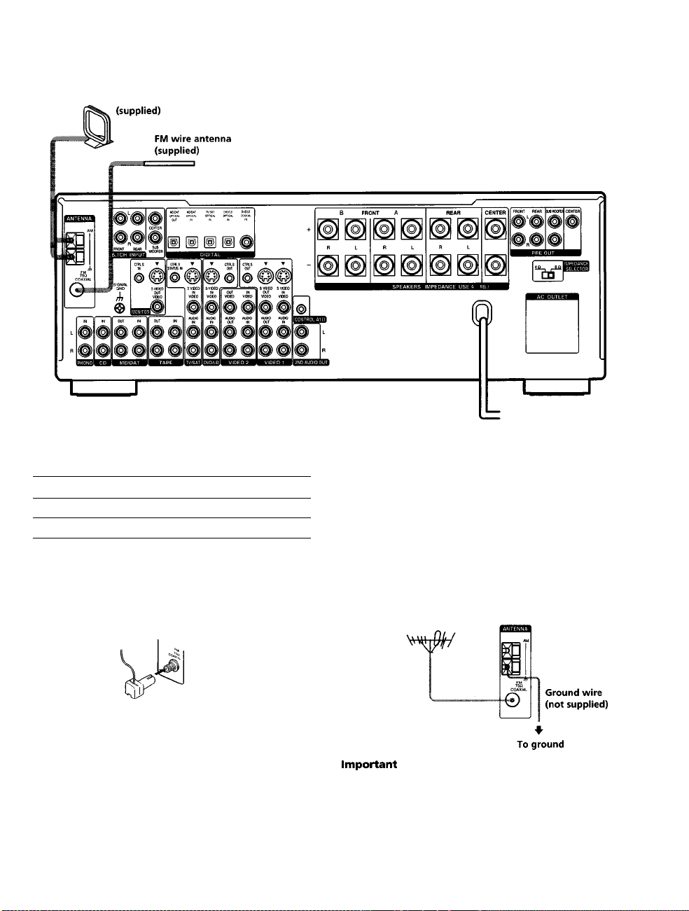
Antenna Hookups
AM loop antenna
iBmilnals for connecting ttie antennas
Connect the
AM loop antenna
FM wire antenna
To the
AM terminals
FM 75Q COAXIAL terminal
Notes on antenna hooku|>s
• To prevent noise pickup, keep the AM loop anterma
away from the receiver and other components
• Be sure to fully extend the FM wire antenna
• After connecting the FM wire antenna, keep it as
horizontal as possible
X
O
o
3'
(fi
(D
n
o
3
?
3
«
#U»emi}ling tite swpplieci FM antenna
(Models of area code U,CA only)
The supplied FM wire antenna must be cormected to the
supplie(J FM antenna adaptor
^ If you have poor FM reception
Use a 75-ohm coaxial cable (not supplied) to connect the receiver
to an outdoor FM antenna as shown below
Outdoor FM antenna
Receiver
If you cormect the receiver to an outdoor anterma, ground
it against lightning To prevent a gas explosion, do not
cormect the ground wire to a gas pipe
Note
Do not use the rh SIGNAL GND terminal for grounding the
receiver
Page 6
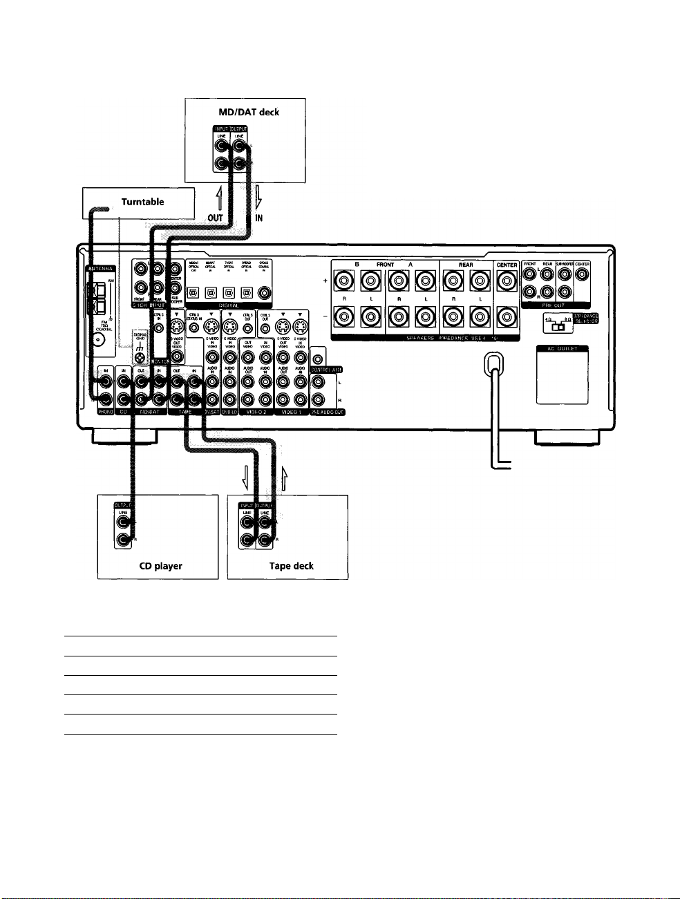
Audio Component Hookups
STR-DB940
s
5T
3*
9
3
3
ID
Required cords
Audio cords (not supplied)
When connecting a cord, be sure to match the color-coded pins to
the appropriate jacks on the components
Red (R) Red (R)
I
Jacks for connecting audio components
Connect a To the
Turntable
CD player
Tape deck
MD deck or DAT deck
Note on audio component hookups
If your turntable has a ground wire, connect it to the
ih
SIGNAL GND terminal on the receiver
PHONO jacks
CD jacks
TAPE jacks
MD/DAT jacks
Page 7
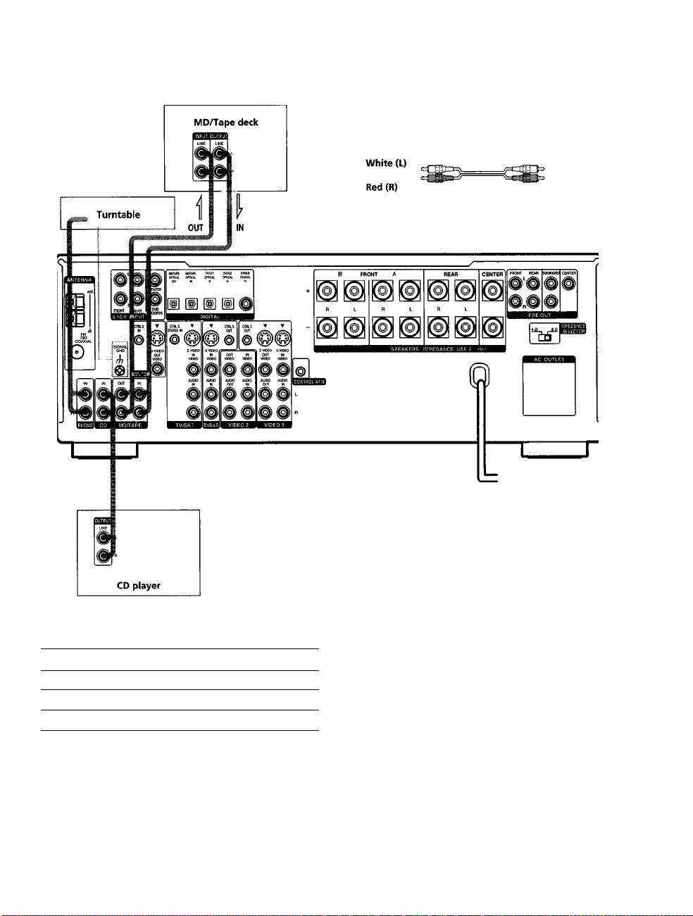
STR-DB840
Required
Audio cords (not supplied)
When connecting a cord, be sure to match the color-coded pins to
the appropriate jacks on the components
White (L)
Red (R)
0
0
5'
in
9
3
i
3
Jeclcs for c<mnecting audio com^ionents
Connect a
Turntable
QD player
MD deck or tape deck
Note on audio eom}K>nent hoc^URS
If your turntable has a ground wire, connect it to the
/h
SIGNAL GND terminal on the receiver
To the
PHONO jacks
CD jacks
MD/TAPE jacks
Page 8
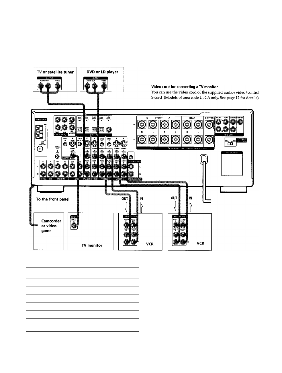
Video Component Hookups
Required cords
0
O
9T
3*
<0
tt
9
3
o
3
»
3
cr
Audio/video cords (not supplied)
When connecting a cord, be sure to match the color-coded pins to
the appropriate jacks on the components
Yellow (video)
White (L/audio) White (L/audio)
Red (R/audio) Red (R/audio)
iadks for connectitig video €Oiti|»oiient5
Connect a
TV or satellite tuner
VCR
Additional VCR
DVD or LD player
TV monitor^*
Camcorder or video game
For STR-DB940, you can display the SURROUND, LEVEL,
EQUALIZER parameters by pressing the ON SCREEN button
on the remote
8
To the
TV/SAT jacks
VIDEO 1 jacks
VIDEO 2 jacks
DVD/LD jacks
MONITOR VIDEO OUT jack
VIDEO 3 INPUT jacks on the
front panel
Note OR video comfmnent hookutm
You can connect your TV's audio output jacks to the TV /
SAT AUDIO IN jacks on the receiver and apply sound
effects to the audio from the TV In this case, do not
connect the TV's video output jack to the TV/ SAT VIDEO
IN jack on the receiver If you are cormecting a separate
TV tuner (or satellite tuner), connect both the audio and
video output jacks to the receiver as shown above
9 When using the S-video jacks instead of the video jacks
Your monitor must also be cormected via an S-video jack S-video
signals are on a separate bus from the video signals and will not
be output through the video jacks
Page 9
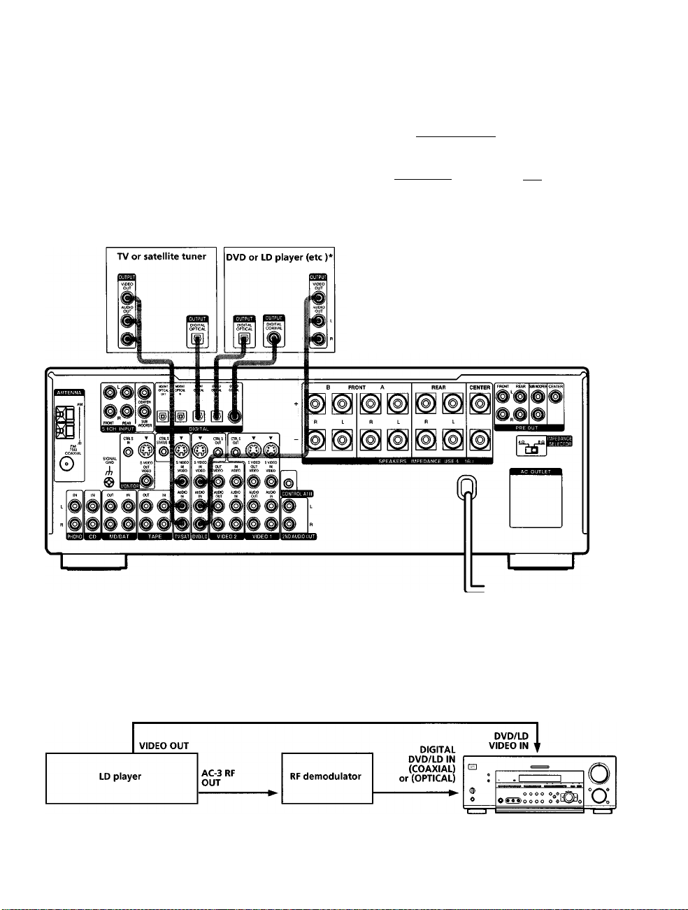
Digital Component Hookups
Connect the digital output jacks of your DVD player and
satellite tuner (etc ) to the receiver's digital input jacks to
bring the multi channel surround sound of a movie
theater into your home To enjoy full effect of multi
channel surround sound, five speakers (two front
speakers, two rear speakers, and a center speaker) and a
sub woofer are required You can also connect an LD
player with an RF OUT jack via an RF demodulator, like
the Sony MOD-RFl (not supplied)
Required cmtb
Optical digital cords (not supplied)
Black ■diirigiBl"" - --- - --- --- - --- --- - --
Coaxial digital cord (not supplied)
Yellow =11 1111111=
Audio/video cords (not supplied)
When connecting a cord, be sure to match the color-coded pins to
the appropriate jacks on the components
Yellow (video) Yellow (video)
White (L/audio) white (L/audio)
Red (R/audio) Red (R/audio)
ariiib- Black
=011111 Yellow
Z
o
o
if
I'
€
?
3
Ì
3
№
I
* Make either coaxial or optical connections We recommend making coaxial connections instead of optical connections
Example of LO player cmmected via an RjF demcNlulator
Please note that you cannot connect an LD player's AC-3 RF OUT jack directly to this unit's digital input jacks You must
first convert the RF signal to either an optical or coaxial digital signal Cormect the LD player to the RF demodulator, then
connect the RF demodulator's optical or coaxial digital output to this unit's OPTICAL or COAXIAL DVD/LD IN jack
Refer to the instruction manual supplied with your RF Demodulator for details on AC-3 RF hookups
Note
When making connections as shown above, be sure to set INPUT MODE ([^ on page 27) manually This unit may not operate correctly if
INPUT MODE is set to "AUTO "
Page 10
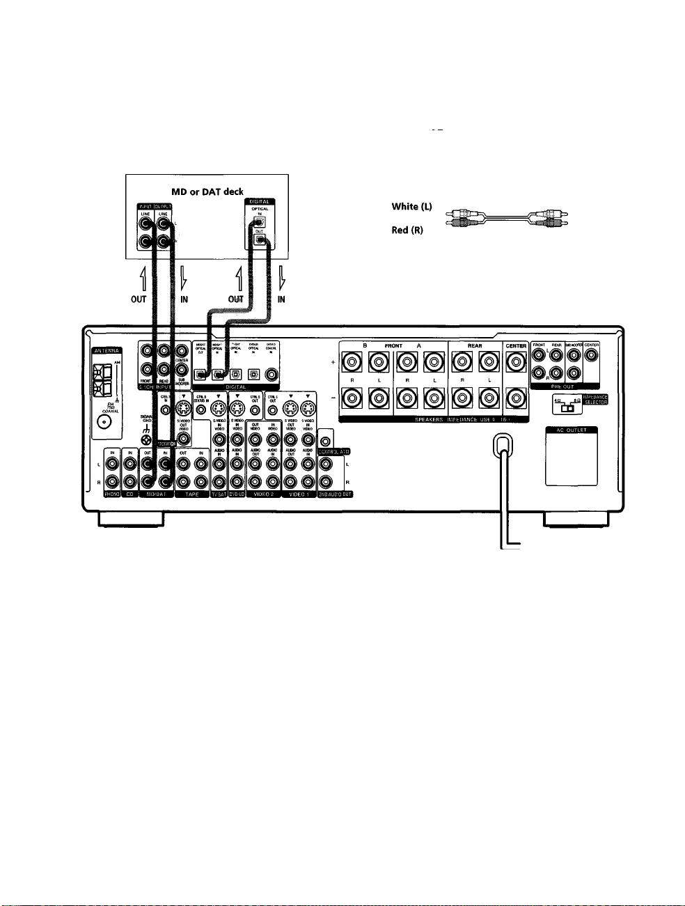
Digital Component Hookups
Ifi
•u
Connect the digital output jacks of your MD or DAT deck
to the receiver's digital input jack and connect the digital
X
input jacks of your MD or DAT deck to the receiver's
8
digital output jack These connections allow you to make
3'
digital recordings of a CDs played back through your
DVD (or LD player) and satellite broadcasts
n
o
3
0
3
(p
3
cr
Recfuired tmdbi
Optical digital cords (not supplied)
Black dirisaa- =
Audio cords (not supplied)
When connecting a cord, be sure to match the color-coded pins to
the appropriate jacks on the components
sTlfe Black
White (L)
Red (R)
Notes
• Please note that you cannot make a digital recording of a digital multi channel surround signal
• To make a digital recording from your CD player, connect the CD player's digital output directly to the digital input on your MD or DAT
deck Refer to the instructions supplied with your CD player and MD or DAT deck for details
• The DVD / LD IN OPTICAL and COAXIAL jacks are compatible with 96 kHz, 48 kHz, 441 kHz and 32 kHz sampling frequencies The
other OPTICAL jacks are compatible with 48 kHz, 44 1 kHz and 32 kHz sampling frequencies
• It is not possible to record analog signals to TAPE and VIDEO with only digital connections To record analog signals, make analog
connections To record digital signals, make digital connections
• Input signals with 96 kHz sampling frequencies to the DVD/LD IN OPTICAL or COAXIAL jacks Using other jacks may result in
intermittent sound
10
Page 11
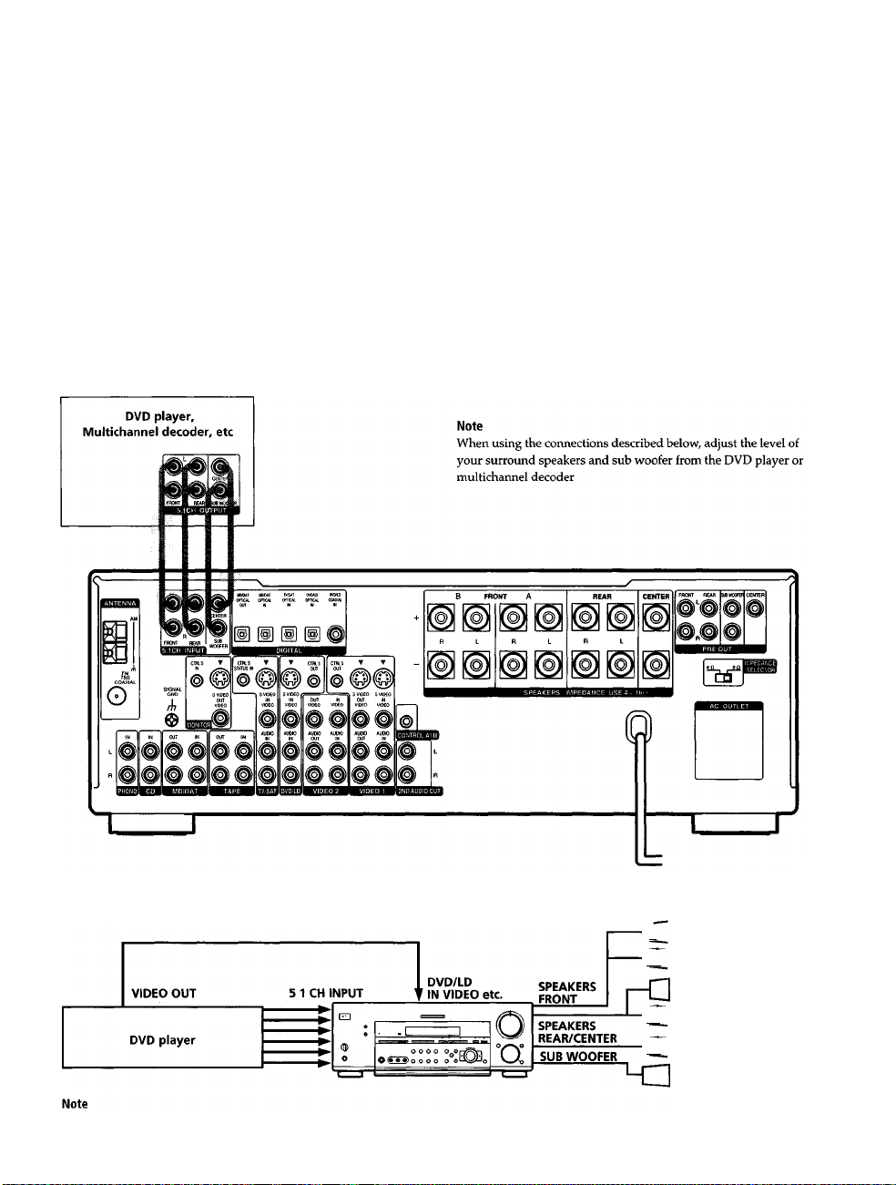
5.1 CH Input Hookups
Although this receiver incorporates a multi chatmel
decoder, it is also equipped with 5 ICH INPUT jacks
These connections allow you to enjoy multicharmel
software encoded in formats other than Dolby Digital
(AC-3) and DTS If your DVD player is equipped with
5 ICH OUTPUT jacks, you can coimect them directly to
this unit to enjoy the sound of the DVD player's multi
channel decoder Alternatively, the 5 ICH INPUT jacks
can be used to coimect an external multi channel decoder
To fully enjoy multi channel surround sound, you will
need five speakers (two front speakers, two rear speakers,
and a center speaker) and a sub woofer Refer to the
instruction manual supplied with your DVD player, multi
channel decoder, etc, for details on the 5 1 channel input
hookups
R«<|uir«d cords
Audio cords (not supplied)
Two for the 5 ICH INPUT FRONT and REAR jacks
White (L)
Red (R)
Monaural audio cords (not supplied)
Two for the 5 ICH INPUT CENTER and SUB WOOFER jacks
Black
Video cord (not supplied)
One for the DVD/LD VIDEO IN jacks (etc )
Yellow Yellow
=1=010= Black
White (L)
Red (R)
X
8
5‘
I
9
3
3
«
I
Example of a DVD player hookup using the S.ICH INPUT jacks
See page 16 for details on speaker system hookup
-f I
Front Speaker (L)
~T ~| Front Speaker (R)
Rear Speaker (L)
~r ~| Rear Speaker (R)
~T ~| Center Speaker
Active Woofer
11
Page 12
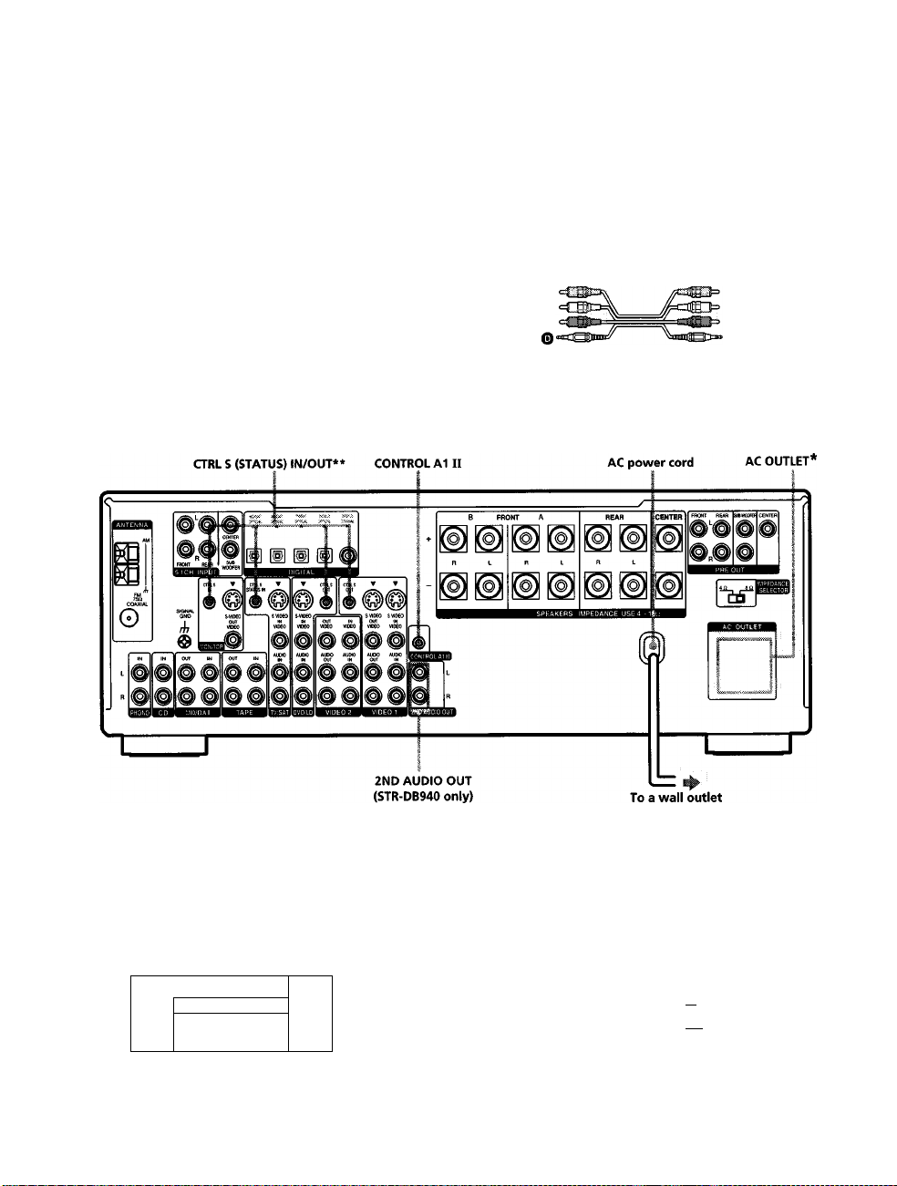
other Hookups
8
K
i
€
»
?
3
?
3
A
3
GT
Required cords
Audio cords (not supplied)
When connecting a cord, be sure to match the color-coded pins to the
appropriate jacks on the components
White (L) White (L)
Red (R)
Audio/video/control S connecting cord (1)*
Yellow (video)
White (L/audio) O
Black (control S)
Control S connecting cord (1)**
O
Red (R/audio) O
Black
0 ocaaBiiii=
mDEE» Black
Red (R)
Yellow (video)
White (L/audio) O
Red (R/audio) O
Black (control S) O
0
O
* The configuration, shape, and number of AC outlets on the rear panel varies according to the model and country to which the receiver is shipped
** Models of area code U. CA only.
Example of a sub RK»n hookup using the 2ND AUDIO OUT Jades (S^-DB940 only)
You can use the 2ND AUDIO OUT jacks to output the audio signal of the selected component to a stereo amplifier located
in another room Use MODE and FUNCTION
Main room
CD
•
•
1
dD
0
Note
This function is not available when 5 ICH INPUT is selected
12
-----
—! ,,
(S]
on pages 26 and 27) to switch the audio signal output to the sub room
Sub room
AUDIO
IN
Stereo amplifier
SPEAKERS
o
•T r*
a
AUDIO
OUT
■f~^ Speaker (L)
■{ L~| Speaker (R)
Page 13
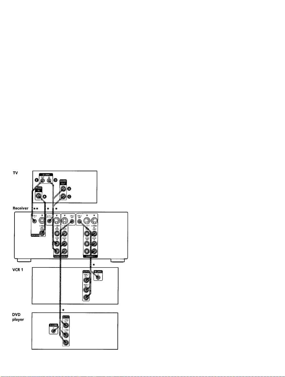
S-ilNK COWmOL S hmOmp
(WlcMci«ls of ama code ll,CA only)
If you have a S-LINK CONTROL S-compatible Sony TV,
satellite tuner, monitor, DVD player or VCR, use an
audio/video/control S coimecting cord (supplied) or a
control S connecting cord (supplied) to connect the CTRL
S (STATUS) IN (for TV, satellite tuner, or monitor) or OUT
(for VCR, etc ) jack on the receiver to the appropriate SLINK jack on the respective component Refer to the
operating instructions supplied with your TV, satellite
tuner, monitor, VCR, etc, for details
The following illustration is an example of S-LINK
CONTROL S hookups between the receiver, a TV, a VCR,
and a DVD player When your TV is connected to the
receiver as shown below, the TV input mode will change
to video input whenever you turn on the receiver When
you cormect the receiver as shown below, input mode of
the receiver changes to VIDEO 1 or DVD / LD whenever
you play your VCR or DVD
The following connections also change the input mode of
the receiver to TV whenever you operate your TV
* Audio/video/control S connecting cord (Pull the video cord away
from the supplied audio/video/control S cable for connection O /
Control S connecting cord
Note
Refer to the instmctions supplied with your TV for details
regarding the operations you can control from your TV
CONfftOL A1 u hookup
• If you have a CONTROL A1
II
compatible Sony
CD player, tape deck, or MD deck
Use a CONTROL A1 cord (not supplied) to connect the
CONTROL A1 II jack on the CD player, tape deck, or
MD deck to the CONTROL A1 II jack on the receiver
Refer to "CONTROL AlII Control System" on page 54
and the operating instructions supplied with your CD
player, tape deck, or MD deck for defails
Note
If you make CONTROL A1 II connections from the receiver to
an MD deck that is also connected to a computer, do not
operate the receiver while using the "Sony MD Editor"
software This may cause a malfunction
• If you have a Sony CD changer with a
COMMAND MODE selector
If your CD changer's COMMAND MODE selector can
be set to CD 1, CD 2, or CD 3, be sure to set the
command mode to "CD I" and cormect the changer to
the CD jacks on the receiver
If, however, you have a Sony CD changer with VIDEO
OUT jacks, set the command mode to "CD 2" and
cormect the changer to the VIDEO 2 jacks on the
receiver
O
O
3
ifi
№
n
0
3
1
3
o
3
13
Page 14

■ a
other Hookups
Connecting the AC power cord
e
Before connecting the AC power cord of this receiver to a
o
K
wall outlet:
3'
• Connect the speaker system to the receiver (see page
c
r
?
3
0
3
«
3
cr
16)
• Turn the MASTER VOLUME control to the leftmost
position (0)
Coimect the AC power cord(s) of your audio/video
components to a wall outlet
If you coimect other audio/video components to the AC
OUTLET(s) on the receiver, the receiver will supply power
to the connected component(s), allowing you to turn the
whole system on or off when you turn the receiver on or
off
Caution
Make sure that the total power consumption of the component(s)
connected to the receiver's AC OUTLET(s) does not exceed the
wattage stated on the rear panel Do not connect high-wattage
electrical home appliances such as electric irons, fans, or TVs to
this outlet
Note
If the AC power cord is disconnected for about two weeks, the
receiver's entire memory will be cleared and the demonstration
will start
14
Page 15

Hooking Up
SET UP Cursor buttons
and Setting Up
the Speaker
System
litis chapter describes how to hook
up your speaker system to the
receiver, how to position each speaker,
and how to
enjoy multi channel surround sound.
set up your speakers to
11
1 1
(Q)
©
© (© © ®) 0 o o o
Brief descriptions of buttons and control
used to set up the speaker system
SET UP button:
Press to enter the setup mode when
specifying speaker types and distances
Cursor buttons
«/»: Use to select parameters after
pressing the SET UP button
Jog dial:
Use to adjust the setting of each parameter
O O O 0
jog dial
io
o
°o:
■o
<i
%
C
I
I
15
Page 16
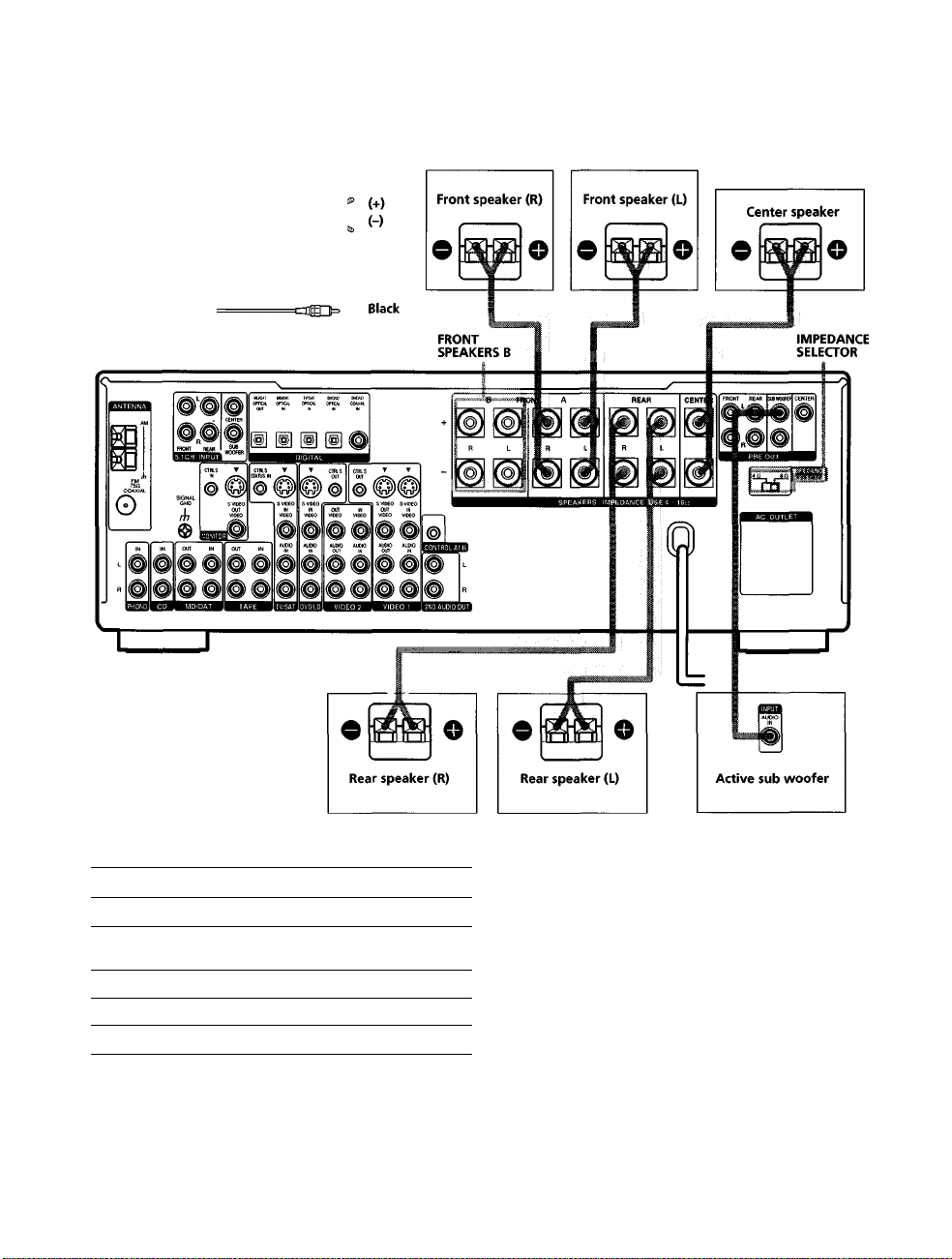
Speaker System Hookup
ccNmds
Speaker cords (not supplied)
One for each front, rear, and center speaker
S
Monaural audio cord (not supplied)
5;
One for an active sub woofer
5'
in
€
i
■o
»<
3
a
lA
I
lA
m
ftp
VI
w
s
3
Black Oct
Temiinals for o»nn«<ting the speakei«
Connect the
Front speakers (8 or 4* ohm)
Additional pair of front
speakers (8 or 4* ohm)
Rear speakers (8 or 4* ohm)
Center speaker (8 or 4* ohm)
Active sub woofer SUB WOOFER PRE OUT**
* See "Speaker impedance" on the next page
** You can connect an active sub woofer to either of the two jacks The
remaining jack can be used to connect a second active sub woofer.
To the
SPEAKERS FRONT A terminals
SPEAKERS FRONT B terminals
SPEAKERS REAR terminals
SPEAKERS CENTER terminals
16
9 To connect certain speakers to another amplifier
Use the PRE OUT jacks The same signal is output from both the
SPEAKERS jacks and the PRE OUT jacks For example, if you
want to connect just the front speakers to another amplifier,
connect that amplifier to the PRE OUT FRONT L and R jacks
Holes on s|»eaker system hookup
• Twist the stripped ends of the speaker cords about
2/3 inch (10 mm) Be sure to match the speaker cord to
the appropriate terminal on the components: + to + and
- to - If the cords are reversed, the sound will be
distorted and will lack bass
• If you use front speakers with low maximum input
rating, adjust the volume carefully to avoid excessive
output on the speakers
Page 17
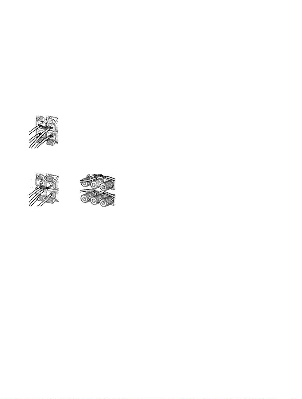
To avoid idiort>€fmiititi9 til« s[^)«af(«i«
short-circuiting of the speakers may damage the receiver
To prevent this, make sure to take the following
precauhons when connecting the speakers
Make sure the stripped ends of each speaker cord
do not touch another speaker terminal or the
stripped end of another speaker cord.
Examples of poor conditions of the speaker cord
*1
stripped speaker cord is touching another speaker terminal
stripped cords are touching each other due to excessive
removal of insulation
To enjoy multi charmel surround, connect front, center,
and rear speakers with a nominal impedance of 8 ohms or
higher, and set the speaker IMPEDANCE SELECTOR to
"8£2 " Check the instruction manual supplied with your
speakers if you're not sure of their impedance (This
information is usually printed on a label on the back of
the speaker)
You may connect a pair of speakers with a nominal
impedance between 4 and 8 ohms to all of the speaker
terminals However, even if one speaker within this range
is connected, set the IMPEDANCE SELECTOR to "4i2"
Note
Be sure to coimect front speakers with a nominal impedance of
8 ohms or higher if you want to select both sets (A+B) of front
speakers (see page 30) In this case, set the IMPEDANCE
SELECTOR to "4n"
la
la
1
3
VI
I
3
A
i/i
»
VI
3
After connecting all the components, speakers,
and AC power cord, output a test tone to check
that all the speakers are connected correctly For
details on outputting a test tone, see page 22.
If no sound is heard from a speaker while outputting a
test tone or a test tone is output from a speaker other than
the one whose name is currently displayed on the
receiver, the speaker may be short-circuited If this
happens, check the speaker cormection again
17
Page 18
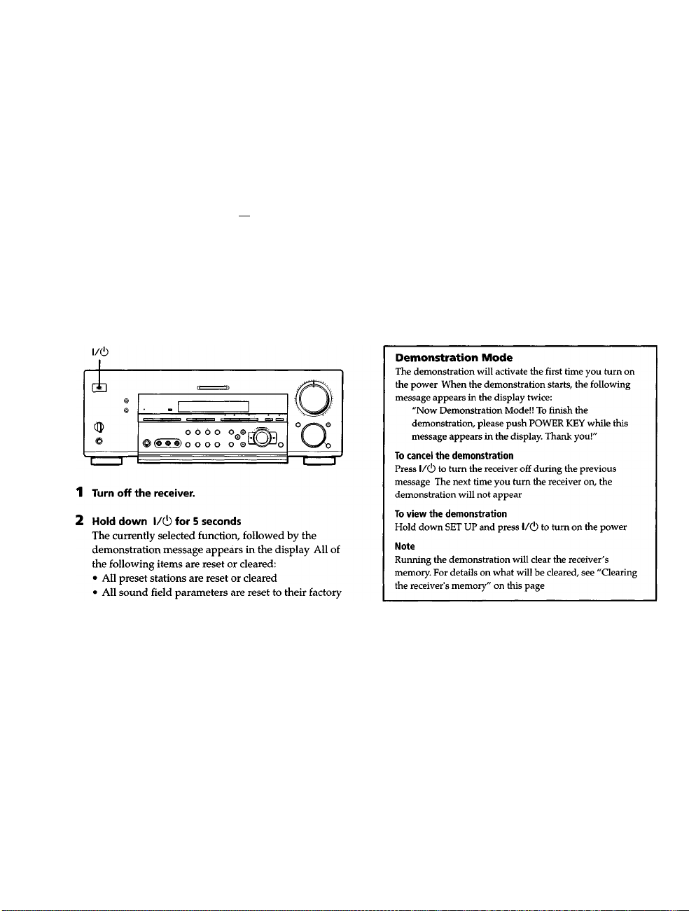
Performing Initial Setup Operations
Once you have hooked up the speakers and turned on the
power, clear the receiver's memory. Then specify the
speaker parameters (size, position, etc ) and perform any
other initial setup operations necessary for your system
Before turning on the receiver
Make sure that you have:
• Turned MASTER VOLUME to the leftmost position (0)
3
<&
Ifi
I
• Selected the appropriate front speakers (see
SPEAKERS selector" on page 30)
3
a
V)
%
3
Before using your receiver for the first time, or when you
want to clear the receiver's memory, do the following
This procedure is not necessary if the demonstration
activates when you turn the power on
3
"l27l
Performing initial setup operations
Before using your receiver for the first time, use the SET
UP button to adjust the setup parameters so that they
correspond to your system You can adjust the following
items For details on how to make adjustments, see the
page in parenthesis
• Speaker size and placement (pages 19-22)
• Speaker distance (page 19)
• Whether other components will turn on or off
automatically via the CONTROL A1 II control system
(page 53)
• Whether the display turns off or not when you press
DIMMER (page 54)
• STR-DB940 only;
- 2 way remote control system operation (page 53)
- Selecting the color of the on-screen display (page 54)
- Select the TV color system of the monitor (except for
models of area U, CA) (page 54)
settings
• All index names (of preset stations and program
sources) are cleared
• All adjustments made with the SET UP button are
reset to their factory settings
• The sound field memorized for each program source
and preset stations are cleared
18
Page 19
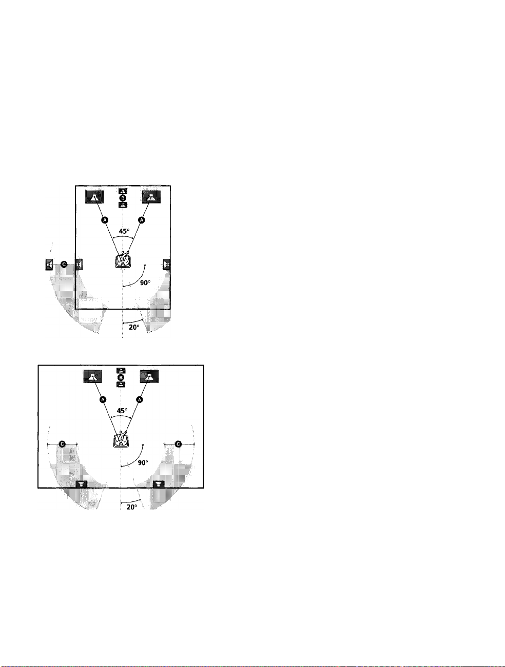
Multi Channel Surround Setup
For the best possible surround sound all speakers should
be the same distance from the listening position (©)
However, this unit lets you to place the center speaker up
to 5 feet (1 5 meters) closer (©) and the rear speakers up
to 15 feet (4 5 meters) closer (©) to the listening position
The front speakers can be placed from 3 to 40 feet (1 0 to
12 0 meters) from the listening position (©)
You can place the rear speakers either behind you or to
the side, depending on the shape of your room (etc)
When placing rear speakers to your side
® i.i!
When placing rear speakers behind you
Specifying ttie sft«ali«Mr
1 Press l/c!) to turn on the receiver.
2 Press SET UP.
3 Press the cursor buttons « or »to select the
parameter you want to adjust
4 Turn the jog dial to select the setting you desire
The setting is entered automatically.
5 Repeat steps 3 and 4 until you have set all of the
parameters that follow
■ Front speaker size (FRONT)
Initial setting: LARGE
• If you coimect large speakers that will effectively
reproduce bass frequencies, select "LARGE" Normally,
select "LARGE"
• If the sound is distorted, or you feel a lack of surround
effects when using multi chaimel surround sound,
select "SMALL" to activate the bass redirection circuitry
and output the front channel bass frequencies from the
sub woofer
• When the front speaker is set to "SMALL", the center
and rear speakers are also automatically set to
"SMALL" (unless previously set to "NO")
X
s
(Q
e
fii
3
a
ÌA
I
I'
9
fil
K
9
Ì
9
3
Note
Do not place the center speaker farther away from the listening
position than the front speakers
19
Page 20

Multi Channel Surround Setup
fÙ
I'
■o
I
■ Center speaker size (CENTER)
Initial setting: LARGE
• If you connect a large speaker that will effectively
reproduce bass frequencies, select "LARGE" Normally,
select "LARGE" However, if the front speakers are set
to "SMALL", you cannot set the center speaker to
"LARGE"
• If the sound is distorted, or you feel a lack of surround
s
7T
S
c
fi)
3
a
V)
S
Ifi
V)
fi)
jr
A
V)
3
effects when using multi channel surround sound,
select "SMALL" to activate the bass redirection circuitry
and output the center chaimel bass frequencies from the
front speakers (if set to "LARGE") or sub woofer.
• If you do not connect a center speaker, select "NO" The
sound of the center channel will be output from the
front speakers
■ Rear speaker size (REAR)
Initial setting: LARGE
• If you coimect large speakers that will effectively
reproduce bass frequencies, select "LARGE" Normally,
select "LARGE" However, if the front speakers are set
to "SMALL", you cannot set the rear speakers to
"LARGE"
• If the sound is distorted, or you feel a lack of surround
effects when using multi channel surround sound,
select "SMALL" to activate the bass redirection circuitry
and output the rear channel bass frequencies from the
sub woofer or other "LARGE" speakers
• If you do not coimect rear speakers, select "NO"
Q' *1-*3 correspond to the following Dolby Pro Logic modes
NORMAL
PHANTOM
3 STEREO
0 About speaker sizes (LARGE and SMALL)
Internally, the LARGE and SMALL settings for each speaker
determine whether or not the internal sound processor will cut
the bass signal from that channel When the bass is cut from a
channel, the bass redirection circuitry sends the corresponding
bass frequencies to the sub woofer or other "LARGE" speakers
However, since bass sounds have a certain amount of
directionality, it best not to cut them, if possible Therefore, even
when using small speakers, you can set them to "LARGE" if you
want to output the bass frequencies from that speaker On the
other hand, if you are using a large speaker, but prefer not to
have bass frequencies output from that speaker, set it to
"SMALL"
If the overall sound level is lower than you prefer, set all speakers
to "LARGE" If there is not enough bass, you can use the
equalizer to boost the bass levels To adjust the equalizer, see
page 40
■ Rear speaker position (REAR PLACE)*
Initial setting: BEHIND
This parameter lets you specify the location of your rear
speakers for proper implementation of the Digital Cinema
Sound surround modes in the "VIRTUAL" sound fields
Refer to the illustration below
• Select "SIDE" if the location of your rear speakers
corresponds to section O
• Select "MIDDLE" if the location of your rear speakers
corresponds to section
• Select "BEHIND" if the location of your rear speakers
corresponds to section O
This setting only effects the surround modes in the
"VIRTUAL" sound fields
O
A El
20
u
f
° 0
""20°
il
--fl
© I
e 1
Page 21
■ Rear speaker height (REAR HEIGHT)*
Initial setting: LOW
This parameter lets you specify the height of your rear
speakers for proper implementation of the Digital Cinema
Sound surround modes in the "VIRTUAL" sound fields
Refer to the illustration below
• Select "LOW" if the location of your rear speakers
corresponds to section O
• Select "HIGH" if the location of your rear speakers
corresponds to section ©
This setting only effects the surround modes in the
"VIRTUAL" sound fields
J
iio.
* These parameters are not available when "Rear speaker
size (REAR)" is set to "NO"
V
This setting is designed specifically for implementation of the
Digital Cinema Sound modes in the "VIRTUAL" sound fields
With the Digital Cinema Sound modes, speaker position is not as
critical as other modes All of the modes in the "VIRTUAL"
sound fields were designed under the premise that the rear
speaker would be located behind the listening position, but
presentation remains fairly consistent even with the rear speakers
positioned at a rather wide angle However, if the speakers are
pointing toward the listener from the immediate left and right of
the listening position, the "VIRTUAL" sound fields will not be
effective unless the rear speaker position parameter is set to
"SIDE"
Nevertheless, each listening environment has many variables,
like wall reflections, and you may obtain better results using
"BEHIND" or "MIDDLE" if your speakers are located high above
the listening position, even if they are to the immediate left and
right
Therefore, although it may result in a setting contrary to the
"Rear speaker position" explanation, we recommend that you
playback multi channel surround encoded software and listen to
the effect each setting has on your listening environment Choose
the setting that provides a good sense of spaciousness and that
best succeeds in forming a cohesive space between the surround
sound from the rear speakers and the sound of the front speakers
If you are not sure which sounds best, select "BEHIND" and then
use the speaker distance parameter and speaker level
adjustments to obtain proper balance
About the rear speaker position (SIDE, MIDDLE, and BEHIND)
■ Sub woofer selection (SUB WOOFER)
Initial setting: YES
• If you connect a sub woofer, select "YES"
• If you do not connect a sub woofer, select "NO" This
activates the bass redirection circuitry and outputs the
LEE signals from other speakers
• In order to take full advantage of the Dolby Digital
(AC-3) bass redirecHon circuitry, we recommend setting
the sub woofer's cut off frequency as high as possible
■ Front speaker distance (FRONT)
Initial setting : 16 feet* (5 0 meter)
Set the distance from your listening position to the front
(left or right) speaker (O on page 19)
• Front speaker distance can be set in 1 foot* (0 1 meter)
steps from 3 to 40 feet* (1 0 to 12 0 meters)
• If both speakers are not placed an equal distance from
your listening position, set the distance to the closest
speaker
• Models of area code U, CA only
■ Center speaker distance (CENTER)
Initial setting : 16 feet* (5 0 meter)
Set the distance from your listening position to the center
speaker
• Center speaker distance can be set in 1 foot* (0 1 meter)
steps from a distance equal to the front speaker distance
(O on page 19) to a distance 5 feet* (1 5 meters) closer to
your listening position (© on page 19)
• Do not place the center speaker farther away from your
listening position than the front speakers
• Models of area code U, CA only
■ Rear speaker distance (REAR)
Initial setting : 11 feet* (3 5 meter)
Set the distance from your listening position to the rear
(left or right) speaker
• Rear speaker distance can be set in 1 foot* (0 1 meter)
steps from a distance equal to the front speaker distance
(© on page 19) to a distance 15 feet* (4 5 meters) closer
to your listening position (© on page 19)
• Do not place the rear speakers farther away from your
listening position than the front speakers
• If both speakers are not placed an equal distance from
your listening position, set the distance to the closest
speaker
• Models of area code U, CA only
la
•o
la
n
•a
0
O
ST
5'
c
SI
3
a
VI
IS
c
I*
S'
IS
M
fli
<D
l/t
9
3
21
Page 22

Multi Channel Surround Setup
Q
About speaker distances
This unit allows you to input the speaker position in terms of
distance However, it is not possible to set the center speaker
further tftan the front speakers Also, the center speaker cannot be
set more that 5 feet* (15 meters) closer than the front speakers
Likewise, the rear speakers can not be set farther away from die
listening position than the front speakers And they can be no
more than 15 feet* (4 5 meters) closer
This is because incorrect speaker placement is not conducive to
3
(fi
I'
the enjoyment of surround sound
Please note that, setting the speaker distance closer than the
actual location of the speakers will cause a delay in the output of
fi)
the sotmd from that speaker In other words, the speaker will
3
a
sound like it is farther away.
For example, setting the center speaker distance 3~6 feet* (1~2 m)
I
closer than die actual speaker position will create a fairly realistic
sensation of being "inside" the screen If you cannot obtain a
satisfactory surround effect because the rear speakers are too
close, setting the rear speaker distance closer (shorter) than the
Ì
actual distance will create a larger soundstage
fi
(/)
Adjusting these parameter while listening to the sound often
fi
results in much better surround sound Give it a try!
fi)
* Models of area code U, CA only.
■ Distance unit (DIST. UNIT)
Initial setting : feet* (meter)
Lets you select either feet or meters as the unit of measure
for setting distances 1 foot corresponds to a 1 ms
difference
* Models of area code U, CA only
■ Front speaker crossover frequency
(FRONT SP >)
Initial setting : 120 Hz
Lets you adjust the front speaker bass crossover frequency
when the front speakers are set to "SMALL" The
frequency can be adjusted in 30 Hz steps from 60 Hz to
180 Hz
■ Center speaker crossover frequency
(CENTER SP >)
Initial setting; 120 Hz
Lets you to adjust the center speaker bass crossover
frequency when the center speaker is set to "SMALL"
The frequency can be adjusted in 30 Hz steps from 60 Hz
to 180 Hz
liiSMfcSfljgl TDw SfPSiaiiwwjr vOitiilSw
Use the remote while seated in your listening position to
adjust the volume of each speaker
Note
This unit incorporates a new test tone with a frequency centered
at 800 Hz for easier speaker volume adjustment
1 Press l/C!) to turn on the receiver.
2 Press TEST TONE on the front panel (except for
models of area code CED) or on the supplied
remote
You will hear the test tone from each speaker in
sequence
3 Adjust the volume level so that the volume of the
test tone from each speaker sounds the same
when you are in your main listening position
• To adjust the balance of the front right and front left
speakers, use the front balance parameter in the
LEVEL menu (see page 39)
• To adjust the balance of the rear right and rear left
speakers, use the rear balance parameter in the
LEVEL menu (see page 39)
• To adjust the volume level of the center speaker,
press the LEVEL CENTER +/ - buttons on the
remote
• To adjust the volume level of the rear speakers, press
the LEVEL REAR + /- buttons on the remote
4 Press TEST TONE again to turn off the test tone
Note
The test tone cannot be output when the receiver is set to 5 ICH
INPUT
9 You can adjust the volume level of all speakers at the same
time
Rotate MASTER VOLUME on the main unit or press MASTER
VOLUME +/- on the remote
■ Rear speaker crossover frequency (REAR SP >)
Initial setting : 120 Hz
Lets you adjust the rear speaker bass crossover frequency
when the rear speakers are set to "SMALL" The
frequency can be adjusted in 30 Hz steps from 60 Hz to
180 Hz
22
Page 23
Notes
• The front balance, rear balance, center level, and rear level are
shovm in the display during adjustment
• Although these adjustments can also be made via the front
panel using the LEVEL menu (when the test tone is output, the
receiver switches to the LEVEL menu automatically), we
recommend you follow the procedure described above and
adjust the speaker levels from your listening position using the
remote control
Before You Use Your Receiver
Before turning on the receiver
Make sure that you have:
• Turned MASTER VOLUME to the leftmost position (0)
• Selected the appropriate front speakers (see "1^
SPEAKERS selector" on page 30)
Checking the connections
After connecting all of your components to the receiver,
do the following to verify that the connections were made
correctly
FUNCTION
1 Press l/(!) to turn on the receiver.
2 Rotate FUNCTION to select a component (program
source) that you connected (e g , CD player or tape
deck)
s
7T
Z
(0
e
fii
3
a
Vk
A
3
(fi
c
7
A
VI
n
III
7T
9
■I
in
•<
Hi
9
3
3 Turn on the component and start playing it
4 Rotate MASTER VOLUME to turn up the voiume
If you do not obtain normal sound output after
performing this procedure, look for the' reason in the
checklist on the following page and take the appropriate
measures to correct the problem
23
Page 24

Before You Use Your Receiver
There is no sound no matter which component is
seiected.
Check that both the receiver and all components
are turned on
^ Check that the MASTER VOLUME control is not
set at 0
o
0
9T
5*
in
c
•o
e
3
a
in
1
I'
e
i/i
I
3
^ Check that the SPEAKERS selector is not set to
OFF or to a position for front speakers that are not
coimected to the receiver (see "i?] SPEAKERS
selector" on page 30)
^ Check that all speaker cords are connected
correctly
^ Press the MUTING button to turn off the indicator
on the button
There's no sound from a specific component.
Check that the component is connected correctly to
the audio input jacks for that component
^ Check that the cord(s) used for the cotmection is
(are) fully inserted into the jacks on both the
receiver and the component
No sound is heard from one of the front
speakers.
^ Coimect a pair of headphones to the PHONES jack
and set the SPEAKERS selector to OFF to verify
that sound is output from the headphones (see "|27|
SPEAKERS selector" and "PHONES jack" on page
30)
If only one chaimel is output from the headphones,
the component may not be cormected to the
receiver correctly Check that all the cords are fully
inserted into the jacks on both the receiver and the
component
If both channels are output from the headphones,
the front speaker may not be coimected to the
receiver correctly Check the connection of the
front speaker which is not outputting any sound
If you encounter a problem that is not included above, see
"Troubleshooting" on page 56
24
Page 25

Hooking Up and Setting Up the Speaker System
in
fsl
Page 26

Location of
Parts and Basic
Operations
This chapter provides information
about the locations and functions of
the buttons and controls on the front
panel. It also explains basic
operations.
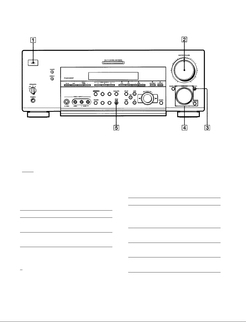
Front Panel Parts
Description
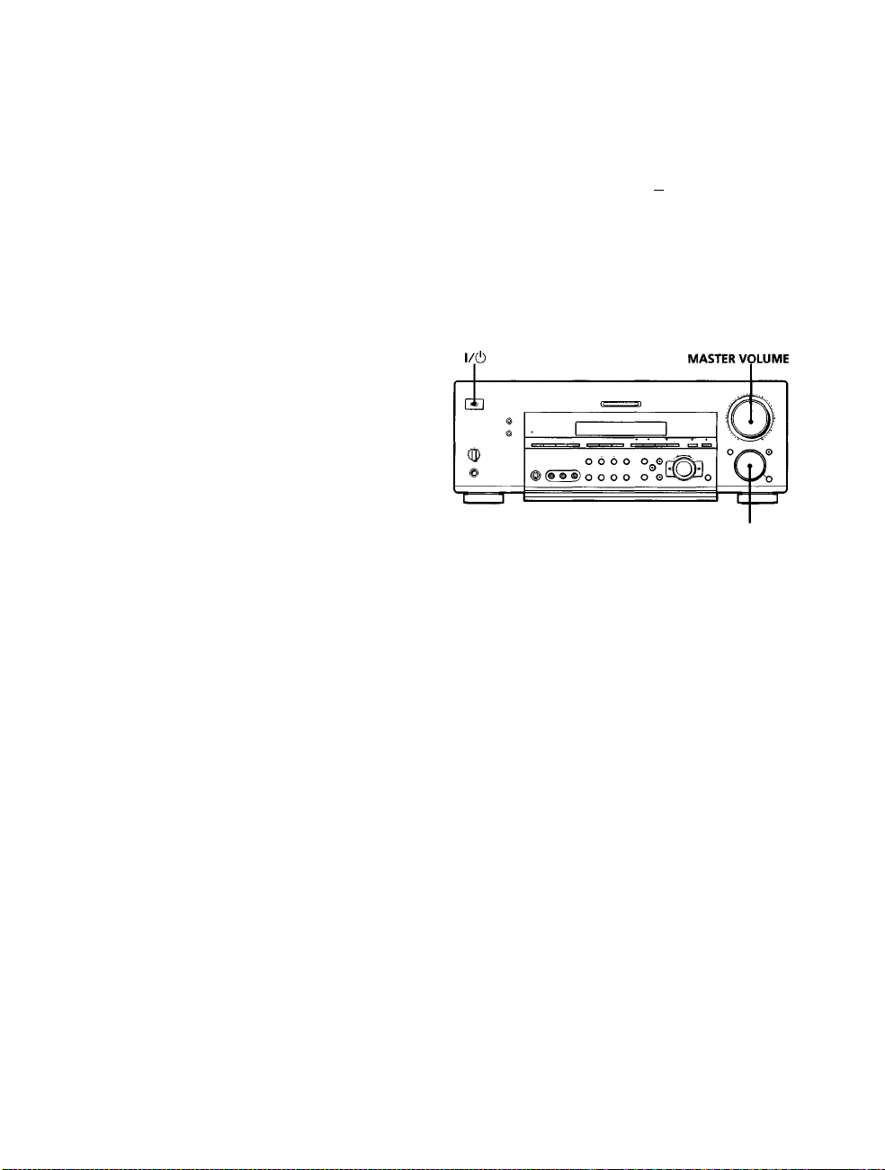
[T] l/(!) switch
Press to turn the receiver on and off
• Before you turn on the receiver, make sure that you have
turned the MASTER VOLUME control to the leftmost
position to avoid damaging your speakers
d] MASTER VOLUME control
After turning on the component you selected, rotate to
adjust the volume
[3] MUTING button
Press to mute the sound The indicator on the button
lights up when the sound is muted
26
g] FUNCTION control
Rotate to select the component you want to use
To select Rotate to light
VCR VIDEO 1 or VIDEO 2
Camcorder or video game VIDEO 3
DVD or LD player DVD/LD
TV or satellite tuner TV/SAT
Tape deck
MD or Tape deck
MD or DAT deck MD/DAT (STR-DB940 only)
CD player CD
Built in tuner TUNER
Turntable PHONO
After selecting the component, turn on the component
you selected and play the program source
• After selecting VCR, camcorder, video game, DVD player,
or LD player, turn on the TV and set the TV's video input
to match the component you selected
TAPE (STR-DB940)
MD/TAPE (STR-DB840)
•
Page 27
?
s
5'
3
u
ai
3
a
CB
at
MODE button
Press to select and play another video/audio source in
combination with the selected component
Each time you press the button, the display changes as
follows:
Standard display (When 5 1CH INPUT is not selected)
I
---
► V:>
• selected component <
When 5 1CH INPUT is selected
> V:XXX
l:
5 ICH INPUT ^
• STR-DB940 only
Press MODE to display And rotate FUNCTION to select
V:XXX
A:XXX Any audio source to enjoy with
2ND AUDIO [XXX] An audio source (except
(STR-DB940 only) PHONO) to enjoy in your sub
* Even if 2ND AUDIO [SOURCE] is selected, no sound is output
when the receiver is set to 5 ICH INPUT Only signals from
components connected to the analog inputs are output through
the 2ND AUDIO jacks No signals are ouput from components
connected to only the digital inputs
Any video source to enjoy with
the audio from the selected
component
the video from the selected
component
room "SOURCE" selects the
same program source as the main
FUNCTION control*
V Function indicators
Normally, the indicator above the selected function lights orange
However, when MODE is used to select a different video (V:XXX)
or audio (A:XXX) source, the video function lights green and the
audio function lights orange This also occurs when you select
audio components (like CD)
m INPUT MODE button
Press to select the input mode for your digital
components (DVD/LD, TV/SAT, and MD/DAT
(STR-DB940) or MD/TAPE (STR-DB840))
Each press switches the input mode of the currently
selected component
Select
AUTO Give priority to digital signals
DIGITAL (OPTICAL) Specify the digital audio signals
DIGITAL (COAXIAL)
ANALOG Specify the analog audio signals
To
when there are both digital and
analog connections If there are
no digital signals, analog is
selected
input to the DIGITAL OPTICAL
input jacks
Specify the digital audio signals
input to the DIGITAL COAXIAL
input jacks (DVD / LD only)
input to the AUDIO IN (L and R)
jacks
■o
■g
>
3
0
1
5'
3
27
Page 28
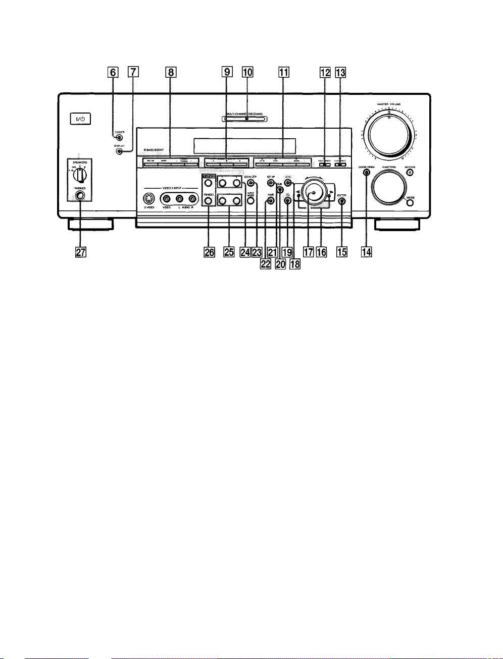
Front Panel Parts Description
fi»
3
a
QB
fii
S*
>
m DIMMER button
3
*3
Press repeatedly to adjust the brightness of the display
When you want to turn off the display set in the
"DIMM RANGE" parameter in the SET UP menu
o
a
(page 54)
¡7} DISPLAY button
Press repeatedly to change the information on the
display wiijdow as follows:
Index name of the component
Sound field applied to the program source
-f-
Selected component
f
* Index name appears only when you have assigned one to the
component or preset station (see page 51) Index name does not
appear when only blank spaces have been entered, or it is the
same as the function button
** These indications appear only during RDS reception (Models of
area code CED only See page 47)
]
The following buttons operate the built-in tuner For
details, see "Receiving Broadcasts" starting from page
43
FM/AM button
Selects the FM or AM band
SHIFT button
Selects a memory page for preset stations
When the tuner is selected
or program station name**
Sound field applied to the band
28
f JieIndex name of the preset station*
♦
Frequency
e
Program type indication**
■f
Radio text**
'#■
Current time**
or the preset station
PRESET TUNING +/- buttons
Scans all preset stations
[E CINEMA STUDIO EX A-C buttons
Press to select CINEMA STUDIO EX A~C sound field
For details, see "CINEMA STUDIO EX A~C" on page
33
m MULTI CHANNEL DECODING indicator
This indicator lights when the unit is decoding signals
recorded in a multi channel format
Page 29

01)
Use these buttons to enjoy surround sound For
details, see "Enjoying Surround Sound" starting from
page 31
A F.D button / indicator
Press to set the receiver to automatically detect the
type of audio signal being input and perform proper
decoding (if necessary) For details, see "AUTO
FORMAT DECODING" on page 35
2CH button / indicator
Press to output sound from only the front (left and
right) speakers For details, see "2 CHANNEL" on
pate 35
MODE +/- buttons / indicator
Press repeatedly to select the sound field you desire
For details, see "Selecting a Sound Field" on page 32
• Sound fields are not compatible with 96 kHz digital audio
signals
03 ANLG DIREa button
Press to listen to an analog source without digital
processing by the equalizer, sound field, etc
For details, see "ANALOG DIRECT" on page 35
03 5 1CH INPUT button
Press to enjoy the audio source cormected to the 5 ICH
INPUT jacks Press 5 1 CH again to return to the
original function
• When 5 ICH INPUT is selected, the equalizer, bass boost,
and sound field effects do not function
011 DOOR OPEN button
Press to open the door on the front panel
01 ENTER button
Press to enter individual characters for the preset
station and program source names
03 Cursor buttons (</>)
Press to select various speaker level, surround, and
equalizer parameters (etc)
07) Jog dial
Turn to adjust the selected speaker level, surround,
and equalizer parameters (etc )
I LEVEL button
Press to activate the speaker level parameters (page
39) The indicator on the button lights up and you can
adjust the various speaker level parameters (front
balance, rear balance, etc )
I EQ button
Press to activate the equalizer parameters (page 40)
The indicator on the button lights up and you can
adjust the various equalizer parameters
I
SUR button
Press to activate the surround parameters (page 38)
The indicator on the button lights up and you can
adjust the various surround parameters (effect level,
wall type, etc)
1 SET UP button
Press to activate the setup mode, then use the cursor
buttons (03) to select any of the following parameters
You can make various settings using the jog dial (07|)
When you select You can
Speaker setup Specify the front, center, rear speaker
Speaker Distance
Crossover
frequency*
Auto Function Specify whether or not Sony components
2 way remote
(STR-DB940 only)
Color system
(STR-DB940 of area
codes other than
U, CA)
OSD color
(STR-DB940 only)
Dimmer Range Specify the display to turn off when you
Only when the speaker is set to"SMALL" in the speaker setup
parameter
sizes, the rear speaker position, and
whether or not you are using a sub
woofer (page 19)
Specify the front, center, and rear speaker
distances and the unit of measurement
(page 21)
Specify the front, center, and rear speaker
bass crossover frequency (page 22)
connected via Control A1 cords will turn
on or off when selected using the
function buttons (page 53)
Turn on or off response to remote
signals sent from the 2 way remote (page
53)
Select the TV color system of the monitor
Specify the color of the on-screen
display (page 54)
press the DIMMER button several times
(page 54)
•a
•a
III
Д
in
fil
3
a
a
tt
M.
n'
>
3
о
29
Page 30

Front Panel Parts Description
NAME button
Press to activate the name function and enter names
for preset stations and program sources (page 51)
I
EQUALIZER button
Press to turn the equalizer on or off The EQ indicator
I The following buttons operate the built-in tuner For
details, see "Receiving Broadcasts" starting from page
43
MEMORY button
Press to memorize a preset station
in the display lights in the display when the equalizer
is turned on
When you adjust the equalizer using the EQ
parameters (page 40), the settings are stored
automatically and can be reproduced whenever you
FM MODE button
If "STEREO" flashes in the display and the FM stereo
reception is poor, press this button You will not have
the stereo effect but the sound is improved
turn on the equalizer
I SPEAKERS selector
• The equalizer is not compatible with 96 kHz digital audio
signals and during 5ICH input
|24| The following buttons operate the built-in tuner For
gi
3
0.
tB
ai
»
o'
>
3
V
»
0
Ti
1
0
3
details, see "Receiving Broadcasts" starting from page
43
Models of area code CED
TUNING/PTY SELECT +/- buttons
Scans all the available radio stations
Selects program types during PTY operations
Models of other area codes
TUNING +/- buttons
Scans all the available radio stations
Models of area code CED
The following buttons operate the built-in tuner
For details, see "Using the Radio Data System
(RDS)" starting from page 47
RDS EON button
Press to set the receiver to automatically switch to
stations broadcasting traffic aimouncements, news,
or information program The EON button does not
function during AM reception
Set according to the front speakers you want to drive
Setto To select
A
B
A+B’ The speakers connected to both the FRONT
OFF No speaker output
• Be sure to connect front speakers with a nominal impedance of
8 ohms or higher if you want to select both sets (A+B) of front
speakers In this case, set the IMPEDANCE SELECTOR to
"4Q"
The speakers connected to the FRONT
SPEAKERS A terminals
The speakers connected to the FRONT
SPEAKERS B terminals
SPEAKERS A and B terminals (parallel
connection)
PHONES jack
Connects headphones
• To use the headphones, set the SPEAKERS selector to OFF
to output sound to the headphones
• To enjoy surround sound from the headphones, we
recommend selecting the HEADPHONE THEATER sound
field Selecting other sound fields when the SPEAKERS
selector is set to OFF automatically presents a 2 channel
(stereo) downmix from the headphones
RDS PTY button
Press to scan stations by program type The PTY
button does not function during AM reception
Models of other area codes
TEST TONE button
Press to output the test tone
SLEEP button
Press to activate the sleep Hmer
30
Page 31

Enjoying
Surround
Sound
This chapter describes how to set up
the receiver to enjoy surround sound.
You can enjoy multi channel surround
when playing back softw'are encoded
with Dolby Digital or DTS.
You can take advantage of surround sound simply by
selecting one of the receiver's pre-programmed sound
modes They bring the exciting and powerful sound of
movie theaters and concert halls into your home You can
also customize the sound modes to obtain the sound you
desire by changing the various surround parameters
The receiver contains a variety of different sound modes
The cinema sound modes are designed for use when
playing back movie software (DVD, LD, etc ) encoded
with multi channel surround sound or Dolby Pro Logic
In addition to decoding the surround sound, some of
these modes also provide sound effects commonly found
in movie theaters
The viitual sound modes contain compelling applications
of the Sony Digital Cinema Sound digital signal
processing technology They shift the sound away from
the actual speaker locations to simulate the presence of
several "virtual" speakers
The music (etc ) sound modes are designed for use with
standard audio sources and TV broadcasts They add
reverberation to the source signal to make you feel as if
you were in a concert hall or stadium (etc ) Use these
sound modes with two-channel sources like CD and
stereo broadcasts of sports programs or musical concerts
For more information about the sound modes, see pages
33-35
AF.D
The "Auto Format Decoding" sound mode presents the
sound exactly as it was encoded, without adding any
reverberation (etc )
m
3
I,
3
c
3
c
3
o.
V)
0
c
3
a
To fully enjoy surround sound, you must register the
number and location of you speakers See "Multi Channel
Surround setup" starting on page 19 to set the speaker
parameters before enjoying surround sound
31
Page 32

CINEMA STUDIO EX A~C SUR LEVEL
Selecting a Sound Field
You can enjoy surround sound simply by selecting one of
the pre-programmed sound fields according to the
program you want to listen to
1 Press MODE +/- repeatedly to select the sound
field you desire
The current sound field is indicated in the display
See the table starting on page 33 for information on
each sound field
Brief descriptions of buttons used to
enjoy surround sound
LEVEL button:
parameters
m
2
o*
SUR button:
parameters in the current sound field
5'
(fi
[A
C
EQ button:
i
parameters in the current sound field
c
3
a
Cursor buttons
VI
o
pressing the LEVEL, SUR, or EQ buttons
e
3
a
Jog dial:
Press to light and customize the level
Press to light and customize the surround
Press to light and customize the equalizer
Use to select parameters after
Use to adjust parameters and select sound fields
To turn the sound field off
Press A F D or 2CH (page 35)
9 The receiver memorizes the last sound field selected for each
program source (Sound Field Link)
Whenever you select a program source, the sound field that was
last applied is automatically applied again For example, if you
listen to CD with STADIUM as the sound field, change to a
different program source, then return to CD, STADIUM will be
applied again With the tuner, sound fields ate memorized
separately for AM, FM, and all preset stations
Q You can identify the encoding format of program software
by looking at its packaging
Dolby Digital discs are labeled with the logo, and Dolby
Surround encoded programs are labeled with the
logo
(etc)
A F.D button:
Press to set the receiver to automatically
detect the type of audio signal being input and perform
proper decoding (if necessary)
2CH button:
Press to output sound from only the front
(left and right) speakers
MODE +/- button:
CINEMA STUDIO EX A~C buttons:
Press to select the sound field
Press to select
CINEMA STUDIO EX A-C sound field
EQUALIZER button:
ANLG DIRECT button:
Turns the equalizer on or off
Press to input the analog signal
without digital processing When this function is on, the
equalizer, bass boost and sound field (etc ) are turned off
32
Page 33

Sound field Effect
NORMAL SURROUND
CINEMA STUDIO EX A'»
(Press CINEMA STUDIO EX A
button)
CINEMA STUDIO EX
(Press CINEMA STUDIO EX B
button)
CINEMA STUDIO EX C'>^>
(Press CINEMA STUDIO EX C
button)
SEMI CINEMA STUDIO EX A" Reproduces the sound characteristics of the Sony
SEMI CINEMA STUDIO EX B*> Reproduces the sound characteristics of the Sony
SEMI CINEMA STUDIO EX C‘>
NIGHT THEATER
MONO MOVIE
STEREO MOVIE
HEADPHONE THEATER Allows you to experience a theater like environment
Software with multi channel surround audio signals is
played according to the way it was recorded
Software with 2 channel audio signals, is decoded with
Dolby Pro Logic to create surround effects
Reproduces the sound characteristics of the Sony
Pictures Entertainment "Cary Grant Theater" cinema
production studio using the 3D sound imaging of
V MULTI DIMENSION {page 34) to create 5 sets of
virtual speakers surrounding the listener from a single
pair of actual rear speakers
Reproduces the sound characteristics of the Sony
Pictures Entertainment "Kim Novak Theater" cinema
production studio using the 3D sound imaging of
V MULTI DIMENSION (page 34) to create 5 sets of
virtual speakers surrounding the listener from a single
pair of actual rear speakers
Reproduces the sound characteristics of the Sony
Pictures Entertainment scoring stage using the 3D
sound imaging of V MULTI DIMENSION (page 34) to
create 5 sets of virtual speakers surrounding the listener
from a single pair of actual rear speakers
Pictures Entertainment "Cary Grant Theater" cinema
production studio using the 3D sound imaging of
V SEMI-M DIMENSION (page 34) to create 5 sets of
virtual speakers surrounding the listener from the
sound of the front speakers (without using actual rear
speakers)
Pictures Entertainment "Kim Novak Theater" cinema
production studio using the 3D sound imaging of
V SEMI-M DIMENSION (page 34) to create 5 sets of
virtual speakers surrounding the listener from the
sound of the front speakers (without using actual rear
speakers)
Reproduces the sound characteristics of the Sony
Pictures Entertainment scoring stage using the 3D
sound imaging of V SEMI-M DIMENSION (page 34) to
create 5 sets of virtual speakers surrounding the listener
from the sound of the front speakers (without using
actual rear speakers)
Allows you to retain a theater like environment while
listening at low volume levels, such as late at night
Creates a theater like environment from movies with
monaural soundtracks
Creates a theater like environment from movies
recorded with stereo soundtracks
while listening through a pair of headphones
Notes
This is a standard mode, great for
watching most any type of movie
This mode is ideal for watching sciencefiction or action movies with lots of sound
effects
This mode is ideal for watching musicals
or classic films where music is featured in
the soundtrack
Ш 0 и
Very effective with 5 Ich discreet signal
sources like Dolby Digital and DTS
I
m
3
(A
C
3
c
3
Q.
fA
0
c
3
a
"VIRTUAL" sound field: Sound field with virtual speakers
However, turning the SUR menu "VIR SPEAKERS" parameter off when using "CINEMA STUDIO EX A~C" or "SEMI CINEMA
STUDIO EX A~C" reproduces the sound characteristics of each cinema production studio without virtual speakers
You can select directly by pressing the buttons on the front panel
33
Page 34

Selecting a Sound Field
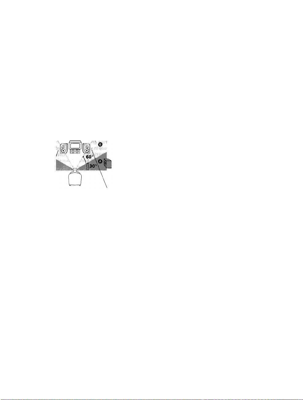
V MULTI DIMENSION'»
{Virtual Multi Dimension)
Effect
Uses 3D sound imaging to create an array of virtual rear
speakers positioned higher than the listener from a
single pair of actual rear speakers This mode creates 5
sets of virtual speakers surrounding the listener at
approximately a 30° angle of elevation
SIDE*
MIDDLE*
i
iv' •
T(;|^
Ù
.....
••
n r
0
i I
%n
h fi
Si @
ri n
0 IbìI
^<6>'
0
i
*
page 20
i
, a
i
Uii i
<8>
i
i
V
*
page 20
<g>
m
2
o'
K
3'
V)
c
c
3
a
(A
o
c
3
a
V MULTI REAR^>
(Virtual Multi Rear)
Uses 3D sound imaging to create 3 sets of virtual rear
speakers from 1 set of actual rear speakers
BEHIND*
SIDE*
MIDDLE*
BEHIND*
0
g i
13 .
i i
i iirt
s
Ì
V SEMI-M DIMENSION'»
(Virtual Semi Multi Dimension)
"VIRTUAL" sound field: Sound field with virtual speakers
Uses 3D sound imaging to create virtual rear speakers
from the sound of the front speakers without using
actual rear speakers This mode creates 5 sets of virtual
speakers surrounding the listener at a 30° angle of
elevation
34
i i
.-I-;: -
i P)T I n
. .-O
" n n ■
f:. -
......
Page 35

Sound field
VIRTUAL ENHANCED A^»
(Virtual Enhanced Surround A)
Effect
Uses 3D sound imaging to create 3 sets of virtual rear
speakers from the sound of the front speakers without
using actual rear speakers
Notes
B 0 0
Mm ^ Mi
VIRTUAL ENHANCED
(Virtual Enhanced Surround B)
SMALL HALL Reproduces the acoustics of a small rectangular concert
LARGE HALL Reproduces the acoustics of a large rectangular concert
OPERA HOUSE Reproduces the acoustics of an opera house
JAZZ CLUB
DISCO/CLUB Reproduces the acoustics of a discotheque/dance club
CHURCH Reproduces the acoustics of a stone church
LIVE HOUSE Reproduces the acoustics of a 300-seat live house
ARENA Reproduces the acoustics of a 1000-seat concert hall
STADIUM Reproduces the feeling of a large open-air stadium
GAME Obtains maximum audio impact from video game
"'VIRTUAL" sound field: Sound field with virtual speakers
Notes
• The effects provided by the virtual speakers may cause increased noise in the playback signal
• When listening to sound fields that emplov the virtual speakers, von will not be able to hear anv sound comine directlv from the rear
speakers
Uses 3D sound imaging to create 1 set of virtual rear
speakers from the sound of the front speakers without
using actual rear speakers
hall
hall
Reproduces the acoustics of a jazz club
software
Ideal for soft acoustic sounds
Ideal for musicals and opera
Great for rock or pop music
Great for sporting events or electric
(amplified) music
Be sure to set the game machine to stereo
mode when using game software with
stereo sound capabilities
0 0 0
m
3
i
VI
c
3
c
3
a
VI
o
c
3
a
Use the buttons on the front panel to operate the following modes
AUTO FORMAT DECODING
(Press the A FD button)
2 CHANNEL
(Press the 2CH button)
ANALOG DIRECT
(Press the ANLG DIRECT
button)
Note
No sound is output from the sub woofer when the 2 CHANNEL mode is selected To listen to two channel (stereo) sources using the front
left and right speakers and a sub woofer, use the AUTO FORMAT DECODING mode
Automatically detects the type of audio signal being
input (Dolby Digital, DTS, Dolby Pro Logic, or standard
2 channel stereo) and performs the proper decoding if
necessary. This mode presents the sound as it was
recorded/encoded, without adding any effects
Outputs the sound from the front left and right speakers
only. Standard two channel (stereo) sources completely
bypass the sound field processing Multi channel surround
formats are downmixed to two channels
The analog input signal is not digitally processed Only
volume control and the balance between the front left
and front right speakers can be adjusted
You can use this mode as a reference Set
the equalizer to OFF while using this mode
to hear the source sound exactly as it was
recorded
This allows you to play any source using
only the front left and right speakers
This mode is suitable for the enjoyment of
high quality analog audio sources
35
Page 36

Understanding the Multi-Channel Surround Displays
L f f _ T
S WOOFERÌSTEREO"
D RANGE ‘ IMONO|
[H OPTICAL
Lights up when the source signal is a digital signal
being input through the OPTICAL terminal
g] COAXIAL
m
5
I'
c
c
3
a.
VI
0
c
3
a
Lights up when the source signal is a digital signal
being input through the COAXIAL terminal
[3] □□ DIGITAL
This indicator lights when a sound field other than
2 CHANNEL is selected and the unit is decoding
signals recorded in the Dolby Digital (AC-3) format *
* However, this indicator does not light when the recording format
is 2/0 or 2/0 Pro logic
[4] Playback charmel indicators
The letters light to indicate the channels being played
back
L; Front Left R: Front Right
C; Center (monaural) LS: Left Surround
RS: Right Surround
S: Surround (monaural or the rear components
obtained by Pro Logic processing)
The boxes around the letters light to indicate the
speakers used to playback the channels
See the next page for details regarding the playback
channel indicators
m LFE
The letters "L F E " light up when the disc being
played contains the LFE (Low Frequency Effect)
charmel When the sound of the LFE charmel signal is
actually being reproduced, the bars underneath the
letters lights up to indicate the level Since the LFE
signal is not recorded in all parts of the input signal
the bar indication will fluctuate (and may turn off)
during playback
E]
S WOOFER
Lights when sub woofer selection is set to "YES" and
this unit detects that the disc being played does not
contain the LFE charmel signal While this indicator is
lit, this unit creates a sub woofer signal based on the
low frequency components of the front channels
[T] Tuner indicators
These indicators light when using the receiver to tune
in radio stations, etc See pages 43~49 for tuner
operations
[8] D RANGE
Lights when dynamic range compression is active See
page 40 to adjust the dynamic range compression
S] PRO LOGIC
Lights when this unit applies Pro Logic processing to
two charmel signals in order to output the center and
surround charmel signals *
* However, this indicator does not light if the center and rear
speakers are set to "NO" and the AFD or NORMAL
SURROUND sound fields are selected
in DTS
Lights up when DTS signals are input
Note
When playing a DTS format disc, be sure that you have made
digital connections and that INPUT MODE is NOT set to
ANALOG {see on page 27)
01] □□
Lights when Dolby Digital (AC-3) signals are input
36
Page 37

Source sound displays
The letters (L, C, R, etc ) indicate the source sound The boxes around the letters vary to show how the receiver downmixes
the source sound (based on the speakers settings) When using music sound modes like LARGE HALL or SMALL HALL
the receiver adds reverberation based on the source sound
The following table shows how the indicators light when using AUTO FORMAT DECODING mode
Although the table below shows almost all of the configurations available from multi charmel surround signals, the ones
marked " ☆ " are the most common
Recording
Format
(Front/Rear)
1/0
2/0*
3/0
2/1
3/1
2/2
3/2
2/0**
Input Channel Display
DOLBY DIGITAL [1/0]
dts [1/0]
DOLBY DIGITAL [2/0]
dts [2/0]
DOLBY DIGITAL [3/0]
dts [3/0]
DOLBY DIGITAL [2/1]
dts [2/1]
DOLBY DIGITAL [3/1]
dts [3/1]
DOLBY DIGITAL [2/2]
dts [2/2]
☆ DOLBY DIGITAL [3/2]
* dts [3/2]
* DOLBY DIGITAL [2/0]
All speakers
present
IbliltJIdbMl
DTS
DTS
lilll»ltdli¿H
DTS
itiiiiiMbui
■tiiiiiMbw
mddMhlJl
DTS iLSi
■^lll^lмiм^
1 PRO LOGIC 1 rsl
Source Sound and Output Channel Display
Qcn
Rear/center
speakers absent
ItlddMblJl
DTS
Rear speakers
absent
[T) rn
DTS
[C]
Center speaker
absent
rfliiltlMhlJl
DTS
[ 1 c O
CD [B B B CD B B B
13 CE
DTS
1
L lie IfRl itiiidMbiiH
[□Cc]®]
DTS
ifckhiMbiJB
m in
n
H IB
DTS S
DTS
[H
mrcirRi
CkDCcDCl]
DTS [13
DTS S
rn n
(LS)
iH
H IB
mrcirRi
(LSI lei
ElcaiB
DTS (Li) iHii
(3I3B
1 PRO LOGIC 1 S
[I3C3CR]
CDnCR]
ItldilMhlJl
DTS LS RS
[I][c]Cr]
DTS LS RS
13 B
rnrnn
rn n
s
3 B
rnrnn
s
rn n
LS RS
13 B
rnrnn
LS RS
13I3B
DTS
lildilMhIill
DTS
■■idi»iM»jRm
mddMbiJi
lilililMblJl
iniiiiMbiJB
[PRO LOGIC 1 ISl
DTS
DTS
CD c [r]
CD c [r]
DTS
13 B
rn c [r]
rgi
B
13 B
C13
rn c [r]
B
CD
in n
ED Hi
B B
oi B1
rn c CD
(lH [m
CD c n
DTS
Hi
B c B
DTS
BUBBIHICD c CD
DTS
■iidtiMbitWm
DTS S
lyáiJMbiJi
rn C CD
DTS S
láláldMblJl rn n
lydJMbitH
1 1 C □
acn
CD
m
CD c CD
CD
s
B B
s
CD c CD
LS RS
B B
DTS LS RS
rn c CD
LS RS
B c m
DTS LS RS
B B
m
3
3
«
c
3
c
3
&
</)
o
c
3
a
B
* DOLBY PROLOGIC
* PCM XX kHz***
1 PRO LOGIC 1 rn
CDIBB
13 B
1 PRO LOGIC 1 S
I3BB
1 PRO LOGIC 1 rn
13 B B B B B
C [R]
* Signals with Dolby surround encoded flag OFF
•• Signals with Dolby surround encoded flag ON
*** Sampling frequency is displayed
Notes
• The receiver performs Pro Logic decoding and the display conforms to 2/0“ when using the following movie sound modes with 2/0* or
STEREO PCM format signals (CINEMA STUDIO EX A, B, C, SEMI CINEMA STUDIO EX A, B, C, NIGHT THEATER, V MULTI
DIMENSION, V MULTI REAR, V SEMI-M DIMENSION, VIRTUAL ENHANCED A, or VIRTUAL ENHANCED B)
• When using music sound modes like LARGE HALL or SMALL HALL with standard audio formats, like PCM, the receiver creates rear
signals from the front L and R signals In this case, sound is output from the rear speakers, but output channel indicators for the rear
speakers do not light
B B
37
Page 38

Customizing Sound Fields
By adjusting the surround parameters and the
equalization of the front, rear and center speakers, you
can customize the sound fields to suit your particular
listening situation
Once you customize a sound field, the changes are stored
in the memory indefinitely (unless the receiver is
unplugged for about two weeks) You can change a
customized sound field any time by making new
adjustments to the parameters
See the table on page 41 for the parameters available in
each sound field
m
2
4
3
la
i/i
c
3
a.
in
0
c
3
a.
To get the most from multi dutimel
surround sound
Position your speakers and do the procedures described
in "Multi Charmel Surround Setup" starting from page 19
before you customize a sound field
The SUR menu contains parameters that let you
customize various aspects of the current sound field The
settings available in this menu are stored individually for
each sound field
1 Start playing a program source encoded with multi
channel surround sound
2 Press SUR
The button lights up and the first parameter is
displayed
Wall type (WALL)
Initial setting: midpoint
When sound is reflected off soft material, such as a
curtain, the high frequency elements are reduced A hard
wall is highly reflective and does not significantly effect
the frequency response of the reflected sound This
parameter lets you control the level of the high
frequencies to alter the sonic character of your listening
enviroiunent by simulating a softer (S) or harder (H) wall
The midpoint designates a neutral wall (made of wood)
Reverberation (REVERB)
Initial setting : midpoint
Before sound reaches our ears, it is reflected
(reverberated) many times between he left and right
walls, ceiling, and floor In a large room, sound takes more
time to bounce from one surface to another than in a
smaller room This parameter lets you control the spacing
of the early reflections to simulate a sonically longer (L) or
shorter (S) room
• The reverberation can be adjusted ±8 from S (short, -8)
to L (long, +8) in 17 steps
• The midpoint (0) designates a standard room with no
adjustment
Screen depth (SCREEN DEPTH)
Initial setting : MID
In a movie theater, sound seems to come from inside the
image reflected on the movie screen This parameter
allows you to create the same sensation in your listening
room by shifting the sound of the front speakers "into"
the screen
• The screen depth can be set to OFF, MID, or DEEP
• DEEP provides the greatest amount of screen depth
3 Press the cursor buttons « or »to select the
parameter you want to adjust
4 Turn the jog dial to select the setting you desire
The setting is entered automaticaliy
Effect level (EFFECT)
Initial setting : (depends on sound mode)
This parameter lets you adjust the "presence" of the
current surround effect
38
Virtual speaker (VIR. SPEAKERS)
Initial setting : ON
Allows you turn the virtual speakers created by the
CINEMA STUDIO EX A, B, C and SEMI CINEMA
STUDIO EX A, B, C sound fields off or on
Page 39

Adjusting the level parameters
The LEVEL menu contains parameters that let you adjust
the balance and speaker volumes of each speaker The
settings available in this menu are applied to all sound
fields
Center level (CENTER)
Initial setting : 0 dB
Lets you adjust the level of the center speaker The level
can even be adjusted during 5 1 CH input
• The level can be adjusted in 1 dB steps from -10 dB to
+10 dB
1 Start playing a program source encoded with multi
channel surround sound
2 Press LEVEL
The button lights up and the first parameter is
displayed
3 Press the cursor buttons (■ < or »to select the
parameter you want to adjust
4 Turn the Jog dial to select the setting you desire
The setting is entered automatically
Front balance (FRONT)
Initial setting: center
Lets you adjust the balance between the front left and
right speakers The level can even be adjusted during 5 1
CH input
• The balance can be adjusted ±8 dB in 1 dB steps
• This settings can also be adjusted using the supplied
remote See "Adjusting the speaker volume" (page 22)
Rear balance (REAR)
Initial setting: center
Lets you adjust the balance between the rear left and right
speakers The level can even be adjusted during 5 1 CH
input
• The balance can be adjusted ±8 dB in 1 dB steps
However, during 5 ICH input, the balance can be
adjusted ±4 dB in 1 dB steps
• This settings can also be adjusted using the supplied
remote See "Adjusting the speaker volume" (page 22)
Rear level (REAR)
Initial setting : 0 dB
Lets you adjust level of the rear (left and right) speakers
The level can even be adjusted during 5 1 CH input
• The level can be adjusted in 1 dB steps from -10 dB to
+10 dB However, during 5 ICH input, the level can be
adjusted in 1 dB steps from -6 dB to +10 dB steps
• This settings can also be adjusted directly using the
supplied remote See "Adjusting the speaker volume"
(page 22)
Sub woofer level (SUB WOOFER)
Initial setting : 0 dB
Lets you adjust the level of the sub woofer. The level can
even be adjusted during 5 1 CH input
• The level can be adjusted in 1 dB steps from -10 dB to
+10 dB
LFE (Low Frequency Effect) mix level
Initial setting : 0 dB
This parameter lets you attenuate the level of the LFE
(Low Frequency Effect) channel output from the sub
woofer without effecting the level of the bass frequencies
sent to the sub woofer from the front, center or rear
charmels via the Dolby Digital (AC-3) bass redirection
circuitry
• The level can be adjusted in 1 dB steps from -20 dB to
0 dB (line level) 0 dB outputs the full LFE signal at the
mix level determined by the recording engineer
• Selecting OFF mutes the sound of the LFE channel from
the sub woofer However, the low frequency sounds of
the front, center, or rear speakers are output from the
sub woofer according to the settings made for each
speaker in the speaker setup (page 18-21)
dts LFE (Low Frequency Effect) mix level
Iiutial setting ; 0 dB
This parameter lets you attenuate the level of the LFE
(Low Frequency Effect) channel output from the sub
woofer without effecting the level of the bass frequencies
sent to the sub woofer from the front, center or rear
channels via the "dts" bass redirection circuitry
• The level can be adjusted in 1 dB steps from +10 0 dB to
-20 0 dB (line level)
• Selecting OFF mutes the sound of the LFE chatmel from
the sub woofer However, the low frequency sounds of
the front, center, or rear speakers are output from the
sub woofer according to the settings made for each
speaker in the speaker setup (page 18-21)
to
2
><.
m
o'
3'
VI
c
3
c
3
a
VI
o
c
3
a
39
Page 40

Customizing Sound Fields
Ç
About the level differences in the LFE MIX settings
The "dts LFE MIX" level is set to +10 0 dB and "LFE MIX" (Dolby
Digital) is set to 0 dB This is because there is an initial difference
of 10 dB in the overall mix between the Dolby Digital and dts
LFE channel levels Essentially, with the "dts LFE MIX" level set
to +10 dB and the "LFE MIX (Dolby Digital)" level set to 0 dB,
approximately the same amounts of LFE channel signal are
distributed to the other audio channels in the overall mix
Adjusting the equalizer
The EQ menu lets you adjust the equalization (low, mid,
and high frequencies) of the front, rear and center
speakers The equalizer settings are stored individually
for each sound field
1 Start playing a program source encoded with multi
channel surround sound
Dynamic range compressor (D. RANGE COMP)
Initial setting : OFF
Lets you compress the dynamic range of the sound track
This may be useful when you want to watch movies at
low volumes late at night
• OFF reproduces the sound track with no compression
• STD reproduces the sound track with the dynamic
m
2.
o
»<
5'
(fi
lA
e
c
3
a
V»
o
c
range intended by the recording engineer
• 0 1 -- 0 9 allow you to compress the dynamic range in
small steps to achieve the sound you desire
• MAX provides a dramatic compression of the dynamic
range
Note
Dynamic range compression is possible with Dolby Digital
sources only.
9 About the Dynamic Range Compressor
This parameter allows you to compress the dynamic range of the
soundtrack based on the dynamic range information included in
the Dolby Digital signal "STD" is standard compression, but
because many sources have only light compression, you may not
notice much difference when using 01~0 9
Therefore, we recommend using the "MAX" setting This greatly
compresses the dynamic range and allows you to view movies
late at night at low volumes Unlike analog limiters, the levels are
predetermined and provide a very natural compression
2 Press EQ
The button lights up and the first parameter is
displayed
3 Press the cursor buttons « or »to select the
parameter you want to adjust
4 Turn the jog dial to select the setting you desire
The setting is entered automatically
V You can turn off the equalization without erasing it
The equalizer settings are stored separately for each sound field
Press the EQUALIZER button to turn the EQ indicator off
Front speaker bass adjustment (Level/Frequency)
® Use the cursor buttons «/ >) to select the level (dB)
or frequency (Hz)
(D Use the jog dial to adjust
Repeat until you achieve the sound you desire
• The level can be adjusted ±10 dB in 1 dB steps
• The frequency can be adjusted from 100 Hz to 1 0 kHz
in 21 steps
Front speaker midrange adjustment (Level/
Frequency)
Adjust as described in "Front speaker bass adjustment"
40
— Level (dB)
Frequency (Hz)
The level can be adjusted ±10 dB in 1 dB steps
' The frequency can be adjusted from 500 Hz to 5 kHz in
21 steps
Front speaker treble adjustment (Level/
Frequency)
Adjust as described in "Front speaker bass adjustment"
• The level can be adjusted ±10 dB in 1 dB steps
• The frequency can be adjusted from 1 0 kHz to 10 kHz
in 21 steps
Page 41

Center speaker bass adjustment (Level/
Frequency)
Adjust as described in "Front speaker bass adjustment"
• The level can be adjusted ±10 dB in 1 dB steps
• The frequency can be adjusted from 100 Hz to 1 0 kHz
in 21 steps
Center speaker midrange adjustment (Level/
Frequency)
Adjust as described in "Front speaker bass adjustment"
• The level can be adjusted ±10 dB in 1 dB steps
• The frequency can be adjusted from 500 Hz to 5 0 kHz
in 21 steps
Center speaker treble adjustment (Level/
Frequency)
Adjust as described in "Front speaker bass adjustment"
• The level can be adjusted ±10 dB in 1 dB steps
• The frequency can be adjusted from 1 0 kHz to 10 kHz
in 21 steps
Rear speaker bass adjustment (Level/Frequency)
Adjust as described in "Front speaker bass adjustment"
• The level can be adjusted ±10 dB in 1 dB steps
• The frequency can be adjusted from 100 Hz to 1 0 kHz
in 21 steps
Rear speaker midrange adjustment (Level/
Frequency)
Adjust as described in "Front speaker bass adjustment"
• The level can be adjusted ±10 dB in 1 dB steps
• The frequency can be adjusted from 500 Hz to 5 0 kHz
in 21 steps
Rear speaker treble adjustment (Level/Frequency)
Adjust as described in "Front speaker bass adjustment"
• The level can be adjusted ±10 dB in 1 dB steps
• The frequency can be adjusted from 1 0 kHz to 10 kHz
in 21 steps
Resetting customized sound fields to the
factory settings
1 If the power is on, press l/c!) to turn off the power.
2 Hold down MODE + and press l/C!)
"S F Initialize" appears in the display and all sound
fields are reset at once
Adjustable parameters for each sound
field
SUR
EFFECT WALL REVERBSCREEN VIRTUAL
LEVEL TYPE TIME DEPTH SPEAKER
2CH
AFD
NORMAL SURROUND
CINEMA STUDIO EX A
CINEMA STUDIO EX B
CINEMA STUDIO EX C
SEMI CINEMA STUDIO EX A
SEMI CINEMA STUDIO EX B
SEMI CINEMA STUDIO EX C
NIGHT THEATER
MONO MOVIE
STEREO MOVIE
HEADPHONE THEATER
V MULTI DIMENSION
V MULTI REAR
V SEMI-M DIMENSION
VIRTUAL ENHANCED A
VIRTUAL ENHANCED B
SMALL HALL
LARGE HALL
OPERA HOUSE
JAZZ CLUB
DISCO/CLUB
CHURCH
LIVE HOUSE
ARENA
STADIUM
GAME
5 ICH INPUT
ANALOG DIRECT
♦:can be stored in each sound field
■:The stored parameter is applied to all of the sound fields
><.
la
m
3
o'
3
VI
c
s
c
3
&
vt
o
c
3
a
41
Page 42

Customizing Sound Fieids
Adjustabie paramoters for each sound field (continued)
2CH
AFD
NORMAL SURROUND
CINEMA STUDIO EX A
CINEMA STUDIO EX B
CINEMA STUDIO EX C
SEMI CINEMA STUDIO EX A
m
SEMI CINEMA STUDIO EX B
2.
o
><
la
SEMI CINEMA STUDIO EX C
5’
NIGHT THEATER
(A
c
MONO MOVIE
c
STEREO MOVIE
3
a.
tfi
HEADPHONE THEATER
0
c
3
V MULTI DIMENSION
a
V MULTI REAR
V SEMI-M DIMENSION
VIRTUAL ENHANCED A
VIRTUAL ENHANCED B
SMALL HALL
LARGE HALL
OPERA HOUSE
JAZZ CLUB
DISCO/CLUB
CHURCH
LIVE HOUSE
ARENA
STADIUM
GAME
51CHINPUT
ANALOG DIRECT
LEVEL
FRONT REAR REAR CENTER WOOFER (dts)LFE ORANGE FRONT CENTER REAR
BAL BAL LEVEL LEVEL LEVEL MIX* * COMP.* EQ EQ EQ
EQ
#:can be stored in each sound field
■:The stored parameter is applied to all of the sound fields
* These parameters may not operate depending on the source or may not operate as adjusted For details, see each item in "Adjusting the
level parameters" {page 39)
42
Page 43

Receiving
Broadcasts
This chapter describes how to receive
FM or AM broadcasts and how to
preset selected stations.
You can tune in stations on this receivei in the following
ways:
Automatic FM Memory (AUTOBETICAL)
-Models of area code CED only
You can have the receiver automatically store up to 30 of
the clearest FM and FM RDS stations in alphabetical order
(see page 44)
Direct Tuning
You can enter a frequency of the station you want directly
by using the numeric buttons on the supplied remote (see
page 45)
Automatic Tuning
If you don't know the frequency of the station you want,
you can let the receiver scan all available stations in your
area (see page 45)
Preset Tuning
After you have tuned in stations using Direct Tuning or
Automatic Tuning, you can preset them to the receiver
(see page 46) Then you can tune in any of the stations
directly by entering its 2-character code using the
supplied remote (see page 46) Up to 30 FM or AM
stations can be preset The receiver will also scan all the
stations that you have preset (see page 46)
RDS functions
-Models of area code CED only
This receiver also allows you to use RDS (Radio Data
System), which enables radio stations to send additional
information along with the regular program signal You
can use the following three convenient RDS features:
— Displaying RDS information (see page 47)
— Scanning preset stations by program type (see page
47)
— Using the EON function (see page 48)
3Q
(6
3
(fi
o
fil
a
Note that RDS is operable only for FM stations *
* Not all FM stations provide RDS service, nor do they provide the
same types of services If you aie not familial with the RDS services
in yow aiea, check with youi local radio stations foi details
Before you begin, make sure you have:
• Connected FM and AM antermas to the receiver (see
page 5)
43
Page 44

Brief descriiitiom of buttmis used to
receive broadcasts
Storing FM Stations Automatically (autobetical)
This function lets you store up to 30 FM and FM RDS
staHons in alphabetical order without redundancy
Additionally, it only stores the staHons with the clearest
(This function is for models of area code CED
signals
only)
If you want to store FM or AM staHons one by one, see
"PresetHng radio stations" on page 46
For details on the buttons used in this secHon, see "Brief
descriptions of buttons used to receive broadcasts" on this
page
1 Press 1/(1) to turn off the receiver.
PRESET TUNING +/- buttons:
radio stations
DISPLAY button:
MEMORY button:
3D
1»
ft
«
TUNING/PTY SELECT +/- buttons*:
<
3'
la
available radio stations or select program types
n
3
TUNING +/- buttons**:
SI
a
stations
S
lA
cr
FUNCTION control:
RDS EON button*:
stations automatically
RDS PTY button*:
program type
FM MODE button:
and the FM stereo reception is poor, press this button to
improve the sound You will not be able to enjoy stereo
effect but the sound will be less distorted
Note
If "STEREO" does not appear at all even when the FM broadcast
is received normally, press this button to turn on the "STEREO"
indication
Press to display the RDS information
Uses for memorizing preset stations
Rotate to select the tuner
Press to set the receiver to switch
Press to scan preset stations by the
Press to scan all preset
Press to scan all
Press to scan all available radio
If "STEREO" flashes in the display
2 Flold down MEMORY and press l/Cl) to turn the
receiver back on
"Autobetical select" appears in the display and the
receiver scans and stores all the FM and FM RDS
staHons in the broadcast area
For RDS staHons, the timer first checks for staHons
broadcasting the same program, then stores only the
one with the clearest signal The selected RDS stations
are sorted alphabetically by their Program Service
name, then assigned a two character preset code For
more details on RDS see page 47
Regular FM staHons are assigned two character preset
codes and stored after the RDS station
When done, "AutobeHcal finish" appears in the
display momentarily and the receiver returns to
normal operaHon
Notes
• Do not press any of the buttons on the receiver or supplied
remote during autobetical operation
• If you move to another area, repeat this procedure to store
stations in your new area
• For details on tuning the stored stations, see page 46
• The FM MODE setting is also stored along with the station
• If you move the antenna after storing stations with this
procedure, the stored settings may no longer be valid If this
happens, repeat this procedure to store the stations again
FM/AM button:
SFIIFT button:
for presetting radio stations or tuning to preset stations
* Models of area code CED only
** Except for models of area code CED
Press to select the FM or AM band
Press to select a memory page (A, B, or C)
44
Page 45

Direct Tuning
Automatic Tuning
Use the supplied remote to perform the following
operations For details on the buttons used in this section,
see the operating instructions for the supplied remote
1 Rotate FUNCTION to select the tuner.
The last received station is tuned in
2 Press FM/AM to select the FM or AM band
3 Press D TUNING
4 Press the numeric buttons to enter the frequency
Example!: FM 102 50 MHz
Example 2: AM 1350 kHz
(You don't have to enter the last "0" when the tuning scale is
set to 10 kHz )
®*®-®-®
If you cannot tune in a station and the
entered numbers flash
Make sure you've entered the right frequency If not,
repeat Steps 3 and 4
If the entered numbers still flash, the frequency is not
used in your area
5 If you've tuned in an AM station, adjust the
direction of the AM loop antenna for optimum
reception
For details on the buttons used in this section, see "Brief
descriptions of buttons used to receive broadcasts" on
page 44
1 Rotate FUNCTION to select the tuner.
The last received station is tuned in
2 Press FM/AM to select the FM or AM band
3 Press TUNING (PTY SELECT) + or TUNING (PTY
SELECT)-
Press the + button to scan from low to high; press the button to scan from high to low
The receiver stops scanning whenever a station is
received
When the receiver reaches either end of the
band
Scanning is repeated in the same direction
4 To continue scanning, press TUNING (PTY SELECT) +
or TUNING (PTY SELECT) - again
(P
A
<‘
s'
09
0
ai
a
A
6 Repeat Steps 2 to 5 to receive another station
9 If you try to enter a frequency that is too precise for the
tuning scale
The entered value is automatically rounded up or down
The tuning scale for direct tuning differs depending on the area
code as shown in the following table For details on area codes,
see page 3
Area code FM tuning scale AM tuning scale
U, CA 50 kHz 10 kHz
(can be changed to 9 kHz)*
AU, CN, SP, CED 50 kHz 9 kHz
* To change the AM tuning scale, see page 60
45
Page 46

Preset Tuning
For details on the buttons used in this section, see "Brief
descriptions of buttons used to receive broadcasts" on
page 44
Before tuning to preset stations, be sure to preset them by
performing steps on "Presetting radio stations" below
Tuning to prasat stations
You can tune the preset stations either of the following
two ways
Scanning the preset stations
1 Rotate FUNCTION to select the tuner.
PNhesettling radio stations
1 Rotate FUNCTION to select the tuner.
The last received station is tuned in
2 Tune in the station that you want to preset using
Direct Tuning (page 45) or Automatic Tuning (page
45)
3 Press MEMORY
"MEMORY" appears in the display for a few seconds
Do Steps 4 to 6 before "MEMORY" goes out
4 Press SHiFT to select a memory page (A, B or C)
s
<
3
la
n
S
ai
a
Each time you press SHIFT, the letter "A," "B" or "C"
appears in the display
5 Press PRESET TUNING + or PRESET TUNING - to
select a preset number.
If "MEMORY" goes out before you press the preset
number, start again from Step 3
6 Press MEMORY again to store the station
If "MEMORY" goes out before you press the preset
number, start again from Step 3
7 Repeat Steps 2 to 6 to preset another station
To change a preset number to another station
Do Steps 1 to 6 to preset the new station to the number
The last received station is tuned in
Press PRESET TUNING + or PRESET TUNING repeatedly to select the preset station you want
Each time you press the button, the receiver tunes in
one preset station at a time, in the corresponding order
and direction as follows:
■*B0»
♦CO.-
C2.-.C1*
Using the preset codes
Use the supplied remote to perform the following
operations For details on the buttons used in this section,
see the operating instructions for the supplied remote
1 Rotate FUNCTION to select the tuner.
The last received station is tuned in
2 For remotes without a display:
Press SHIFT to select a memory pare (A, B, or C),
then press the preset number of the station you
want using the numeric buttons on the supplied
remote
For remotes with a display:
Select the preset station you want from the list
displayed on the supplied remote when TUNER is
selected
Note
If the AC power cord is disconnected for about two weeks, all the
preset stations will be cleared from the receiver's memory, and
you will have to preset the stations again
46
Page 47

Using the Radio Data System (RDS)
(This function is for models of area code CED oniy.)
Receiving RDS
Simply select a station on the FM band using direct
tuning (page 45), automatic tuning (page 45), or
preset tuning (page 46)
When you tune in a station that provides RDS services,
the RDS indicator lights up and the program staHon name
appears in the display
Note
RDS may not work properly if the station you tuned to is not
transmitting the RDS signal properly or if the signal strength is
weak
Displaying RDS infoimatiM
While receiving an RDS station, press DISPLAY
repeatedly to change the RDS information on the
display window as follows:
PS (Program Station name)®’
Frequency®’
PTY (Program TYpe) indication'^’
RT (Radio Text) indication*^’
CT (Current Time) indication (in 24-hour system)
Scanning presat stati<m$ by imigram type
You can tune in preset stations according to a program
type that you specify The receiver scans for stations in its
preset memory currently broadcasting the specified
program type
1 Press RDS PTY
Press (TUNING) PTY SELECT + or (TUNING) PTY
SELECT - to select the program type
See the table on the next page for information on each
program type
Press RDS PTY
While the receiver is scanning stations, "PTY
SEARCH" and the program type indication appear
alternately in the display window
When the receiver finds a station, the receiver stops
scanning
When the receiver could not find any preset stations
currently broadcasting the specified program type,
"PTY not found" appears in the display
Using th« ION #Su«ctlo«
The EON (Enhanced Other Network) function allows the
receiver to switch automatically to a station broadcasting
traffic announcements, news, or information programs
When such a program starts on a station networking with
the preset FM RDS station, the receiver automatically
tunes in the station
After the program ends, the receiver switches back to the
original preset station or the program source you were
originally listening to
3)
I
<
5’
ifi
CB
3
D
a
A
D)
Sound field currently applied
a) This information also appears for non-RDS FM stations
b) Type of program being broadcast (See page 48 )
c) Text messages sent by the RDS station
Notes
• If there is an emergency announcement by government
authorities, "Alarm-Alarm!" flashes in the display.
• If a station does not provide a particular RDS service, "No XX"
(such as "No Clock Time") appears in the display.
• When a station broadcasts radio text data, it is displayed at the
same rate at which it is sent from the station Any change in
this rate is reflected in the display rate of the data
47
Page 48

Using the Radio Data System (RDS)
1 Tune in a preset FM RDS station so that the RDS
indicator iights up
2 Press RDS EON repeatediy to seiect the type of the
program to be tuned in
Each time you press the RDS EON button, the
indication for the type of the program lights up
alternately as shown below
I
------------
TA (Traffic Announcement)
NEWS (News)
INFO (Information program)
OFF (No indication lights up )
I
________
9
n
ID
<
3
la
o
SI
a
After selecting the type of the program, you can select
any other component
When the receiver automatically tunes in the program,
the indication that you've selected in Step 2 flashes in
the display
To stop listening to the program
Press RDS EON during program reception The
indication that you've selected in Step 2 lights up and the
receiver switches back to the program source or the
station you were listening to
To turn off the EON function
Press RDS EON repeatedly in Step 2 above so that no
program type indication lights up in the display
Notes
• After selecting the type of the program, if you tune in an AM
station, the program type indicator turns off and the receiver
will no longer tune in the program
• Be sure to turn off the EON function when you want to record a
program without interruptioiw, especially when doing timeractivated recording
• "Weak Signal" appears in the display when the signal of the
program is weak
Destri^itm of pm^rarn types
Program type indication
News
Current Affairs
Information
Sport
Education
Drama
Cultures
Science
Varied Speech
Pop Music
Rock Music
M 0 R Music
Light Classics M
Serious Classics
Other Music
Description
News programs
Topical programs that expand on
current news
Programs offering information
on a wide spectrum of subjects,
including consumer affairs and
medical advice
Sports programs
Educational programs, such as
"how-to" and advice programs
Radio plays and serials
Programs about national or
regional culture, such as
language and social concerns
Programs about the natural
sciences and technology
Other types of programs such as
celebrity interviews, panel
games, and comedy
Popular music programs
Rock music programs
Easy Listening
Instrumental, vocal, and choral
music
Performances of major
orchestras, chamber music,
opera, etc
Music that does not fit into any
categories above, such as
Rhythm & Blues and Reggae
48
Page 49

Program type indication
Weather & Metr
Finance
Children's Progs
Social Affairs
Religion
Phone In
Travel & Touring
Leisure & Hobby
Description
Weather information
Stock market reports and trading,
etc
Programs for children
Programs about people and the
things that affect them
Programs of religious content
Programs where members of the
public express their views by
phone or in a public forum
Programs about travel Not for
announcements that are located
by TP/TA
Programs on recreational
activities such as gardening,
fishing, cooking, etc
Jazz Music Jazz programs
Country Music
National Music
Oldies Music
Folk Music
Documentary
None
Country music programs
Programs featuring the popular
music of the country or region
Programs featuring oldies music
Folk music programs
Investigative features
Any programs not defined above
<p
o
<D
3
Ifi
s
a
n
fil
49
Page 50

rifhar
Operations
SET UP Cursor buttons
Brief descriptions of tHittons that ai^ar
in this chapter
NAME button:
sources
Jog dial:
stations or program sources
Cursor buttons
naming preset stations or program sources
SLEEP button*:
FUNCTION control:
source
SET UP button:
ENTER button:
preset station or program source
Except for models of area code CED
Press to name preset stations or program
Use to select characters when naming preset
«/»: Use to move the cursor when
Press to activate the sleep function
Rotate to select the tuner or other
Press to enter the set up mode
Press to enter the completed name of the
SO
Page 51

Naming Preset Stations and Program Sources
You can enter a name of up to 8 characters for preset
stations and program sources These names (for example,
"VHS") appear in the receiver's display when a station or
program source is selected
Note that no more than one name can be entered for each
preset station or program source
This function is useful for distinguishing components of
the same kind For example, two VCRs can be specified
as "VHS" and "8mm," respectively It is also handy for
identifying components cormected to jacks meant for
another type of component, for example, a second CD
player cormected to the MD/DAT jacks
1 To index a preset station
Rotate FUNCTION to select the tuner.
The last station you received is tuned in
To index a program source
Select the program source (component) to be
named, then go to Step 3
Recording
Your receiver makes it easy to record to and from the
components connected to it You don't have to cormect
the playback and recording components directly to each
other: once you select a program source on the receiver,
you can record and edit as you normally would using the
controls on each component
Before you begin, make sure you've cormected all
components properly
2 Tune in the preset station you want to create an
index name for.
If you are not familiar with how to tune in preset
stations, see "Tuning to preset stations" on page 46
3 Press NAME
4 Create an index name by using the jog dial and
cursor buttons;
Turn the jog dial to select a character, then press > to
move the cursor to the next position
To insert a space
Turn the jog dial until a blank space appears in the
display (the space character is between
If you've made a mistake
Press <[ or ^ repeatedly until the character to be
changed flashes, then turn the jog dial to select the
right character
"II"
and "A")
5 Press ENTER
To assign index names to other stations
Repeat Steps 2 to 5
Note
(Models of area code CED only)
You cannot change the name of an RDS station
Video signal flow
Reccmiing on an audio tape or MinlDisc
You can record on a cassette tape or MiniDisc using the
receiver See the instruction manual of your cassette deck
or MD deck if you need help
1 Select the component to be recorded
2 Prepare the component for playing
For example, insert a CD into the CD player
3 Insert a blank tape or MD into the recording deck
and adjust the recording level, if necessary
4 Start recording on the recording deck, then start
playback on the playback component
Notes
• You cannot record a digital audio signal using a component
connected to the analog TAPE OUT or MD/DAT OUT jacks
(STR-DB940) or the analog MD/TAPE OUT jacks (STR-DB840)
To record a digital audio signal, connect a digital component to
the DIGITAL MD/DAT OUT jacks
(STR-DB940) or the DIGITAL MD / TAPE OUT jacks
(STR-DB840)
• Sound adjustments do not affect the signal output from the
TAPE OUT or MD/DAT OUT jacks (STR-DB940) or the MD/
TAPE OUT jacks (STR-DB840)
O
‘C
ID
51
Page 52

Recording
Using the Sleep Timer
Recording on a video tape
You can record from a VCR, a TV, or an LD player using
the receiver You can also add audio from a variety of
audio sources when editing a video tape See your VCR
or LD player's instruction manual if you need help
1 Select the program source to be recorded
2 Prepare the component for playing
For example, insert the laser disc you want to record
into the LD player
3 Insert a blank video tape into the VCR (VIDEO 1 or
VIDEO 2) for recording
4 Start recording on the recording VCR, then start
playing the video tape or laser disc you want to
record
9 You can record the sound from any audio source onto a
video tape while copying from a video tape or laser disc
Locate the point where you want to start recording from another
audio source, select the program source, then start playback The
audio from that source will be recorded onto the audio track of
the video tape instead of the audio from the original medium
To resume audio recording from the original medium, select the
video source again
O
*0
Notes
• Please be sure to make both digital and analog connections to
the TV / SAT and DVD / LD inputs Analog recording is not
possible if you only make digital connections
• Some sources contain copy guards to prevent recording In this
case, you may not be able to record from the sources
You can set the receiver to turn off automatically at a
specified time
Press SLEEP on the front panel (except for models of
area code CED) or on the remote while the power is
on
Each Hme you press SLEEP, the time changes as shown
below
j—» 2:00:01
► 2:00:00 —*■ 1:30:00-» 1:00:00 -* 0:30:00 -► OFF -
The display dims after you have specified the time
^ You can freely specify the time
First, press SLEEP, then specify the time you want using the jog
dial on the receiver The sleep time changes in 1 minute intervals
You can specify up to 5 hours
Q
You can check the time remaining before the receiver turns
off
Press SLEEP The remaining time appears in the display.
□
52
Page 53

Adjustments Using the SET UP Button
The SET UP button allows you to make the following
adjustments
Adjttsl^ng th« CONTOOL A1 li mAo
Unction
Turning on the Control A1 II auto function parameter lets
you turn Sony components cormected via CONTROL A1
cords (see page 13) on automatically when you press the
corresponding function button
Auto function is set to ON by default
1 Press SET UP.
2 Press the cursor buttons « or »to select "AUTO
FUNCTION "
3 Turn the jog dial to select "ON" or "OFF."
Setting up the 2 way remote
cmly}
This receiver is shipped from the factory with the 2 way
remote control system set to "ON" Normally, you can use
the receiver as is
However, if you want to use this receiver together with
another component that is also compatible with the 2 way
remote control system, be sure to perform the following
operation to limit response to signals sent from the remote
controls
To use with the TA-E9000ES
Perform the following steps to turn OFF this unit's 2 way
remote control system Also, be sure the TA-E9000ES is
turned on when using this unit
To use with other connponents that have the K
iogo
Turn OFF the other component's 2 way remote control
system For details, refer to the operating instructions
suppled with your other components
To use with Sony CD piayers CDP-CX260 or CDPCX88ES
Turn OFF the remote control adapter switch on the
CDP-CX260 or CDP-CX88ES For details, refer to the
operating instructions suppled with the CDP-CX260 or
CDP-CX88ES
2
o
<D
Also when using several 2 way remote control system
components together, be sure to place them close together
in order to enable proper remote operation
1 Press SET UP.
2 Press the cursor buttons (<^ or to select "2 WAY
REMOTE"
3 Turn the jog dial to select "ON" or "OFF"
53
Page 54

Adjustments Using the SET UP Button
Selecting the monitor color system
(STR-DB940 of area code other than U, CA)
Select the color system of your TV morritor You can select
either NTSC or PAL The default setting is PAL
1 Press SET UP.
2 Press the cursor buttons «[ or »to select
"COLOR SYSTEM"
3 Turn the jog dial to select "NTSC" or "PAL"
Selecting the color of the on-screen
display (STR-DB940 only)
Select the color of the on-screen display You can
select either COLOR or MONOCHROME The color of the
on-screen display is set to COLOR by default
1 Press SET UP.
2 Press the cursor buttons « or »to select "OSD
COLOR"
CONTROL A1II Control System
This section explains the basic functions of the
CONTROL A1
have special functions, like "CD Synchro Dubbing" on
cassette decks, that require CONTROL Alll
connections For detailed information regarding
specific operations, be sure to also refer to the
Operating Instructions supplied with your
component(s)
The CONTROL AlII Control System was designed to
simplify the operation of audio systems composed of
separate Sony components CONTROL A1II connections
provide a path for the transmission of control signals
which enable automatic operation and control features
usually associated with integrated systems
Currently, CONTROL AlII connections between a Sony
CD player, amplifier (receiver), MD deck and cassette
deck provide automatic function selection and
synchronized recording
In the future the CONTROL A1II connection will work as
a multifunction bus allowing you to control various
functions for each component
II
Control System Certain components
3 Turn the Jog dial to select "COLOR" or
s
y
ft
o
SI
o
3
ID
"MONOCHROME"
Set the display to turn off
This parameter lets you specify whether or not the display
turns off when you press the DIMMER button several
times When "WIDE" is selected, you can set the display
to turn off, but when "NARROW" is selected, you carmot
set the display to turn off The default setting is set to
"NARROW"
1 Press SET UP.
2 Press the cursor buttons « or »to select "DIMM
RANGE"
3 Turn the jog dial to select "NARROW" or "WIDE"
Notes
• The CONTROL A1II Control System is designed to maintain
upward compatibility as the Control System is upgraded to
handle new functions In this case, however, older components
will not be compatible with the new functions
♦ Do not operate a 2 way remote control unit when the
CONTROL A1II jacks are connected via a PC interface kit to a
personal computer running "MD Editor" or similar application
Also, do not operate the connected component in a manner
contrary to the functions of the application, as this may cause
the application to operate incorrectly.
CONTROL A1II and CONTROL A1 compatibility
The CONTROL A1 control system has been updated to the
CONTROL A1II which is the standard system in the SONY
300 disc CD changer and other recent Sony components
Components with CONTROL A1 jacks are compatible with
components with CONTROL A1II, and can be connected to
each other Basically, the majority of the functions available
with the CONTROL A1 control system will be available with
the CONTROL AlII control system
However, when making connections between components
with CONTROL A1 jacks and components with CONTROL
AlII jacks, the number of functions that can be controlled
may be limited depending on the component For detailed
information, refer to the Operating Instructions supplied with
the component(s)
54
Page 55

Connections
Connect monaural (2P) mini-plug cords in series to the
CONTROL A1II jacks on the back of each component You
can coimect up to ten CONTROL A1II compatible
components in any order However, you can connect only
one of each type of component (i e, 1 CD player, 1 MD
deck, 1 tape deck and 1 receiver)
(You may be able to cormect more than one CD player or
MD deck, depending on the model Refer to the operating
instructions supplied with the respective component for
details)
* (*)
Example
Amplifier CD MD Tape Other
(Receiver) player deck deck component
In the CONTROL A1II control system, the control signals
flow both ways, so there is no distinction of IN and OUT
jacks If a component has more than one CONTROL A1II
jack, you can use either one, or connect different
components to each jack
Jacks and connection examples
CONTROL AID
(*)
(8)
Basic Functions
The CONTROL A1II functions will operate as long as the
component you want to operate is turned on, even if all of
the other cormected components are not turned on
Automatic function selection
When you cormect a CONTROL A1II compatible Sony
amplifier (or receiver) to other Sony components using
monaural mini-plug cords, the function selector on the
amplifier (or receiver) automatically switches to the
correct input when you press the play button on one of
the cormected components
Notes
• You must connect a CONTROL A1 compatible amplifier
(receiver) using a monaural mini-plug cord in order to take
advantage of the automatic function selection feature
• This function only works when the components are cormected
to the amplifier (or receiver) inputs according to the names on
the function buttoirs Certain receivers allow you to switch the
names of the function buttons In this case, refer to the
Operating Instructions supplied with the receiver.
• When recording, do not play any components other than the
recording source It will cause the automatic function selection
to operate
Synchronized recording
This function lets you conduct synchronized recording
between the selected source and recorder components
s
T
9
o
*0
CONTROL A1D
® <
On CONTROL A1 jacks and connections
It is possible to make cormections between CONTROL A1
and CONTROL AlII jacks For details regarding
particular cormecHons or setup options, refer to the
Operating Instructions supplied with the component(s)
About the connecting cord
Some CONTROL A1 compatible components are supplied
with a cormecting cord as an accessory. In this case, use
the cormecting cord for your cormection
When using a commercially available cord, use a
monaural (2P) mini-plug cord less than 2 meters long,
with no resistance (like the Sony RK-G69HG)
CD player
MD deck
1 Set the function selector on the amplifier (or
receiver) to the source component
2 Set the source component to pause mode (make
sure both the ^ and II indicators light together)
3 Set the recorder component to the REC-PAUSE
mode
4 Press PAUSE on the recorder component
The source component is released from the pause
mode, and recording begins shortly thereafter.
When playback ends from the source component,
recording stops
Notes
• Do not set more than one component to the pause mode
• Certain recorder components may be equipped with a special
synchronized recording function that uses the CONTROL A1II
Control System, like "CD Synchro Dubbing" In this case, refer
to the Operating Instructions supplied with the recorder
component
55
Page 56

Additional
Troubleshooting
If you experience any of the following difficulties while
using the receiver, use this troubleshooting guide to help
you remedy the problem Also, see "Checking the
connections" on page 23 to verify that the connections are
correct Should any problem persist, consult your nearest
Sony dealer
There's no sound or only a very low-level sound
is heard.
^ Check that the speakers and components are
cormected securely
^ Make sure that you've selected the correct
component on the receiver
Make sure that you've set the SPEAKERS selector
correctly (see page 30)
^ Press MUTING on the remote if the MUTING
indicator is lit
^ The protective device on the receiver has been
activated because of a short circuit Turn off the
receiver, eliminate the short-circuit problem and
turn on the power again
The left and right sounds are unbalanced or
reversed
^ Check that the speakers and components are
cormected correctly and securely
^ Adjust front balance parameter in the LEVEL
Severe hum or noise is heard.
^ Check that the speakers and components are
cormected securely
^ Check that the coimecting cords are away from a
transformer or motor, and at least 10 feet (3 meters)
away from a TV set or fluorescent light
^ Move your TV away from the audio components
^ Make sure you've grounded
terminal
"► The plugs and jacks are dirty Wipe them with a
cloth slightly moistened with alcohol
Intermittent sound from a digital source
^ Make sure signals with 96 kHz sampling
frequencies are input to the DVD/LD IN OPTICAL
or COAXIAL jacks
ih
SIGNAL GND
Page 57

No sound is heard from the center speaker.
Make sure the sound field function is on (press
SOUND FIELD — MODE)
^ Select a sound field containing the word "cinema"
or "virtual" (see page 33-35)
^ Adjust the speaker volume (see page 22)
^ Make sure the center speaker size parameter is set
to either SMALL or LARGE (see page 20)
No sound or only a very low-level sound Is heard
from the rear speakers
^ Make sure the sound field function is on (press
SOUND FIELD - MODE)
^ Select a sound field containing the word "cinema"
or "virtual" (see page 33-35)
Adjust the speaker volume (see page 22)
^ Make sure the rear speaker size parameter is set to
either SMALL or LARGE (see page 20)
The surround effect cannot be obtained
^ Make sure the sound field function is on (press
SOUND FIELD - MODE)
^ Make sure that the SPEAKERS selector is set to A
or B (not A+B) if you connected two sets of front
speakers
Recording cannot be done
^ Check that the components are coimected correctly
^ Select the source component with a FUNCTION
button
^ When recording from a digital component, make
sure the input mode is set to ANALOG (see page
27) before recording with a component connected
to the analog MD/DAT or TAPE terminals
(STR-DB940) or the analog MD/TAPE terminals
(STR-DB840)
^ When recording from a digital component, make
sure the input mode is set to DIGITAL (see page
27) before recording with the component
connected to the DIGITAL MD/DAT OUT
terminals (STR-DB940) or the DIGITAL MD/TAPE
OUT terminals (STR-DB840)
Radio stations cannot be tuned in
^ Check that the antennas are connected securely
Adjust the antennas and connect an external
antenna if necessary
^ The signal strength of the stations is too weak (when
tuning in with automatic tuning) Use direct tuning
^ Make sure you set the tuning interval correctly
(when tuning in AM stations with direct turung)
(see pages 45 and 59)
No stations have been preset or the preset stations
have been cleared (when tuning by scanning preset
stations) Preset the stations (see page 46)
^ Press DISPLAY so that the frequency appears in
the display
RDS does not work.*
^ Make sure that you're tuned to an FM RDS station
^ Select a stronger FM station
The station was interrupted by another station
or the receiver automaticaily starts scanning
stations *
The EON function is activated Turn off the EON
function if you don't want the current program to
be interrupted
The RDS information that you want does not
appear.*
^ Contact the radio station and find out whether or
not they actually provide the service in question
If so, the service may be temporarily out of order
Nothing appears on the display
“► When the display turns off immediately after the
receiver is turned on, press DIMMER to change the
display mode
No picture or an unclear picture appears on the
TV screen or monitor.
^ Select the appropriate function on the receiver
Set your TV to the appropriate input mode
^ Move your TV away from the audio components
The remote does not function.
^ Point the remote at the remote sensor IS on the
receiver
^ Remove any obstacles in the path between the
remote and the receiver
^ Replace both batteries in the remote with new
ones, if they are weak
^ Make sure you select the correct function on the
remote
^ If the remote is set to operate the TV only, use the
remote to select a source or component other than
TV before operating the receiver or other
component
* Models of area code CED only
Referenc« sections for clearing the
receiver's memory
To clear See
All memorized settings page 18
Customized sound fields page 41
57
I
g.
o‘
3
3
3
%
0
3
Page 58

Specifications
I
a
7
0*
fli
F*
o
AUDIO POWER
SPEPFICATIONS
POWER OUTPUT AND
TOTAL HARMONIC
DISTORTION:
With 8 ohm loads, both
channels driven, from 20 20,000 Hz; rated 110 watts
(STR-DB940) and 100 watts
(STR-DB840) per channel
minimum RMS power,
with no more than 0.09 %
total harmonic distortion
from 250 milliwatts to
rated output (USA model
only).
Ana^HNer smadim
POWER OUTPUT
Models of area code U. CA
Rated Power Output at Stereo Mode
(8 ohms 20 Hz - 20 kHz, THD 0 09 %)
STR-DB940: 110 W +HOW
STR-DB840; lOOW + lOOW
(4 ohms 20 Hz - 20 kHz, THD 0 09 %)
STR-DB940: lOOW + lOOW
STR-DB840: 90W + 90W
3
SL
Reference Power Output
3
(8 ohms 20 Hz - 20 kHz, THD 0 09 %)
3*
STR-DB940; FRONT'»;
i
STR-DB840: FRONT'»:
now +110W
CENTER'»: 110 W
REAR'»;
now +110W
100 W + 100 W
CENTER'»: 100 W
REAR'»:
100 W +100W
(4 ohms 20 Hz - 20 kHz, THD 0 09 %) (8 ohms 20 Hz - 20 kHz, THD 0 09 %)
STR-DB940: FRONT:'» STR-DB940: FRONT'»:
100 W + 100 W 100 W +100W
CENTER'»: 100 W
REAR'»:
100 W + 100 W 100 W +100W
STR-DB840: FRONT'»: STR-DB840: FRONT'»:
Models of other area code
Rated Power Output at Stereo Mode
(8 ohms 1 kHz, THD 0 7 %)
STR-DB940: 110W + 110W^>
STR-DB840; lOOW + lOOW
(4 ohms 1 kHz, THD 0 7 %)
STR-DB940: lOOW + lOOW^»
STR-DB840; 90 W + 90 W
Reference Power Output^»
(8 ohms 1 kHz, THD 0 7 %)
STR-DB940: FRONT'»:
90W +90W 90W +90W
CENTER'»: 90 W
REAR'»:
90W +90W 90 W + 90 W
(4 ohms 20 Hz - 20 kHz, THD 0 09 %)
STR-DB940/DB840:
100 W + 100 W^»
1) Depending on the sound field settings and
90 W + 90 W^>
no w + no W
CENTER'»: 110 W
REAR'»:
the source, there may be no sound output
2) Measured under the following conditions:
Area code Power requirements
AU 240 VAC, 50 Hz
CN,SP,CED 230 VAC, 50 Hz
3) Measured under the folloxving conditions:
Area code Power requirements
CN
CENTER'»: 100 W
REAR":
CENTER'»; 90 W
REAR":
FRONT'»;
90W +90W
CENTER'»: 90 W
REAR'»:
90W +90W
220 VAC, 50 Hz
no w + no W
STR-DB840: FRONT'»:
(4 ohms 1 kHz, THD 0 7 %)
STR-DB940/DB840;
100 W + 100 W
CENTER'»: 100 W
REAR'»:
100 W + 100 W
FRONT'»:
100 W + 100 W
CENTER'»: 100 W
REAR'»:
100 W + 100 W
58
Page 59

Frequency response
PHONO: RIAA
equalization curve
+0 5dB
CD, TAPE, MD/DAT,
MD/TAPE, DVD/
LD, TV/SAT,
VIDEO 1, 2, and
VIDEOS:
10 Hz - 100 kHz
+0 5 /-3 dB (with
sound field,
equalizer, and bass
boost bypassed)
Inputs (Analog)
PHONO:
Sensitivity: 2 5 mV
Impedance: 50
kilohms
S/N^>: 86 dB
(A, 2 5 mV“*))
5 ICH INPUT, CD,
TAPE, MD/DAT,
MD/TAPE, DVD/ 100 Hz~l 0 kHz
LD, TV/SAT, VIDEO (21 steps)
1, 2, and VIDEO 3: MID:
Sensitivity: 150 mV
Impedance:
50 kilohms TREBLE:
S/N^>: 96 dB 1 0 kHz-10 kHz
(A, 150 mV^>)
3) INPUT SHORT
4) Weighted network, input level
Inputs (Digital)
DVD/LD IN(Coaxial):
Sensitivity: Impedance: 75 ohms
S/N: 100 dB
(A, 20 kHz LPF)
DVD/LD IN, TV/SAT
IN, MD/DAT IN
(Optical):
Sensitivity: Impedance: S/N: 100 dB
(A, 20 kHz LPF)
Outputs
TAPE, MD/DAT, MD/
FRONT L/R, CENTER,
PHONES:
BASS BOOST
+6 dB at 70 Hz
Sampling Frequency
48 kHz
EQ
BASS:
TAPE (REC OUT);
VIDEO 1, 2 (AUDIO
OUT):
Voltage: 150 mV,
Impedance:
1 kilohms
REARL/R,
SUB WOOFER:
Voltage: 2 V
Impedance:
1 kilohms
Accepts low- and
high-impedance
headphones
500 Hz-5 0 kHz
(21 steps)
(21 steps)
Gain levels:
±10 dB, 1 dB step
FM tuner section
Tuning range
87 5 -108 0 MHz
Antenna terminals
75 ohms, unbalanced
Sensitivity
Mono: 18 3dBf,
2 2;iV/75ohms
Stereo: 38 3 dBf,
22 5^V/75ohms
Usable sensitivity
112dBf, l;<V/75ohms
S/N
Mono: 76 dB
Stereo: 70 dB
Harmonic distortion at 1 kHz
Mono: 0 3%
Stereo: 0 5%
Separation
45 dB at 1 kHz
Frequency response
30 Hz-15 kHz
+0 5/-2dB
Selectivity
60 dB at 400 kHz
I
Q.
o‘
3
SL
3
S'
3
a
0*
3
59
Page 60

Specifications
AM tuner section
Tuning range
Models of area code U, CA
Models of area code AU, CN, SP, CED
Antenna
Usable sensitivity
S/N
Harmonic distortion
Selectivity
5) You can change the AM tuning scale to
I
a
5‘
3
SL
3
o
3
a
r+
o'
3
9 kHz 10 kHz Aßet tuning in any AM
station, turn off the leceiver. Hold dozen the
TUNING - button and ptess the l/Cll
button All pieset stations zvill be erased
when you change the tuning scale To reset
the scale to 10 kHz (or 9 kHz), repeat the
proceduie
'"Viifeo section
Inputs
With 10-kHz tuning
scale:
530 -1710 kHz^>
With 9-kHz tuning
scale:
531 -1710 kHz^>
With 9-kHz tuning
scale:
531 -1602 kHz
Loop antenna
50dB/m(atl,000 kHz
or 999 kHz)
54 dB (at 50 mV / m)
0 5 % (50 mV / m,
400 kHz)
At 9 kHz: 35 dB
At 10 kHz: 40 dB
Video: 1 Vp-p 75 ohms
S-video:
Y: 1 Vp-p 75 ohms
C: 0 286 Vp-p
75 ohms
Qeneral
System
Power requirements
Power consumption
Tuner section:
Preamplifier section:
Power amplifier
Models of area code U,
Models of area code
Models of area code
Models of area code AU
Models of area code U
Models of area code CA
Models of area code
Models of area code
PLL quartz-locked
digital synthesizer
system
Low-noise NF type
equalizer
section:
Pure-complementary
SEPP
CA
120 V AC, 60 Hz
CED
230 VAC, 50/60 Hz
CN,SP
220 - 230 VAC,
50/60 Hz
240 VAC, 50 Hz
STR-DB940: 290 W
STR-DB840: 280 W
STR-DB940: 400 VA
STR-DB840: 390 VA
CED
STR-DB940: 290 W
STR-DB840: 280 W
CN, SP
STR-DB940: 290 W
Models of area code AU
STR-DB840: 290 W
AC outlets
Models of area code U,
CA
2 switched,
total 120W/1A
Models of area code
AU, SP, CED
1 switched,
total 100 W
Models of area code CN
2 switched,
total 100 W
Dimensions
430 x 161 x 401 mm
(17 X 7 ^/s X 19 ^/8 in )
including projecting
parts and controls
Mass (Approx)
13 2 kg (29 lb 2 oz)
Supplied accessories
See page 4
For details on the area code of the
component you are using, see
page3
Design and specifications are subject
to change without notice
60
Outputs
Video: 1 Vp-p 75 ohms
S-video:
Y: 1 Vp-p 75 ohms
C: 0 286 Vp-p
75 ohms
Page 61

Glossary
Surround sound
Sound that consists of three elements:
direct sound, early reflected sound
(early reflections) and reverberative
sound (reverberation) The acoustics
of the surrounding space affect the
way these three sound elements are
heard Surround sound combines
these sound elements in such a way
that you actually can sense the size of
the venue, as well as its type
• Types of sound
• Transition of sound from rear speakers
Direct sound
Dolby Pro Logic Surround
As one method of decoding Dolby
Surround, Dolby Pro Logic Surround
produces four channels from twochannel sound Compared with the
former Dolby Surround system,
Dolby Pro Logic Surround reproduces
left-to-right parmrng more naturally
and localizes sounds more precisely
To take full advantage of Dolby Pro
Logic Surround, you should have one
pair of rear speakers and a center
speaker The rear speakers output
monaural sound
Reverberation
Dolby Digital (AC-3)
This sound format for movie theaters
is more advanced than Dolby Pro
Logic Surround In this format, the
rear speakers output stereo sound
with an expanded frequency range
and a sub woofer charmel for deep
bass is independently provided This
format is also called "5 1" because the
sub woofer channel is counted as 0 1
channel (since it functions only when
a deep bass effect is needed) All six
charmels in this format are recorded
separately to realize superior charmel
separation Furthermore, since all the
signals are processed digitally, less
signal degradation occurs The name
"AC-3" comes from the fact that it is
the third audio coding method to be
developed by the Dolby Laboratories
Licensing Corporation
Digital Cinema Sound
This is the generic name of the
surround sound produced by digital
signal processing technology
developed by Sony Unlike previous
surround sound fields mainly
directed at the reproduction of music.
Digital Cinema Sound is designed
specifically for the enjoyment of
movies
I
a
o’
3
SL
3
?
i
61
Page 62

Tables of Settings Using SUR, LEVEL, EQ, and SET UP
buttons
You can make various settings using the LEVEL, SUR, EQ, SET UP buttons, jog dial, and cursor buttons The tables below
show each of the settings that these buttons can make
Press and light Press <[ or >• to select
SUR button EFFECT LEVEL
LEVEL button
EQ button FRONT BASS GAIN
I
a
O*
3
fiL
I
3
%
0
3
Turn jog dial to select
depends on sound mode (in 21 steps)
WALL TYPE
REVERBERATION TIME
SCREEN DEPTH OFF, MID, DEEP
VIRTUAL SPEAKER
FRONT BALANCE between -8 dB to +8 dB (in 1 dB steps)
REAR BALANCE
REAR LEVEL
CENTER LEVEL
SUB WOOFER LEVEL between -10 dB to +10 dB (in 1 dB steps)
LEE MIX LEVEL
dts LFE MIX LEVEL OFF, or -20 dB to +10 dB (in 1 dB steps)
DYNAMIC RANGE COMP Off, 0 1 to 0 9 (in 0 1 dB steps), STD, or MAX
FRONT BASS FREQUENCY between 100 Hz and 1 0 kHz (in 21 steps)
FRONT MID GAIN between -10 dB to +10 dB (in 1 dB steps)
FRONT MID FREQUENCY between 500 Hz and 5 0 kHz (in 21 steps)
FRONT TREBLE GAIN between -10 dB to +10 dB (in 1 dB steps)
FRONT TREBLE FREQUENCY between 1 0 kHz and 10 kHz (in 21 steps)
CENTER BASS GAIN between -10 dB to +10 dB (in 1 dB steps)
CENTER BASS FREQUENCY between 100 Hz and 1 0 kHz (in 21 steps)
CENTER MID GAIN between -10 dB to +10 dB (in 1 dB steps)
CENTER MID FREQUENCY between 500 Hz and 5 0 kHz (in 21 steps)
CENTER TREBLE GAIN between -10 dB to +10 dB (in 1 dB steps)
CENTER TREBLE
FREQUENCY
REAR BASS GAIN between -10 dB to +10 dB (in 1 dB steps)
REAR BASS FREQUENCY between 100 Hz and 1 0 kHz (in 21 steps)
REAR MID GAIN between -10 dB to +10 dB (in 1 dB steps)
REAR MID FREQUENCY between 500 Hz and 5 0 kHz (in 21 steps)
REAR TREBLE GAIN between -10 dB to +10 dB (in 1 dB steps)
REAR TREBLE FREQUENCY between 1 0 kHz and 10 kHz (in 21 steps)
between -8 to +8 (in 1 increment steps)
between -8 to +8 (in 1 increment steps)
ON, OFF
between -8 dB to +8 dB (in 1 dB steps)
(during 5 ICH input: ^ dB - +4 dB (in 1 dB steps))
between -10 dB to +10 dB (in 1 dB steps)
(during 5 1 CH input: -6 dB - +10 dB (in 1 dB steps))
between -10 dB to +10 dB (in 1 dB steps)
OFF, or -20 dB to 0 dB (in 1 dB steps)
between -10 dB to +10 dB (in 1 dB steps) 40
between 1 0 kHz and 10 kHz (in 21 steps)
See page
38
39
62
Page 63

Press Press or >• to select Turn jog dial to select
SETUP FRONT [XXX] LARGE or SMALL 19
CENTER [XXX] LARGE, SMALL, or NO
REAR [XXX] LARGE, SMALL, or NO
REAR PLACE [XXX] SIDE, MIDDLE, or BEHIND
REAR HEIGHT [XXX] LOW or HIGH
SUB WOOFER [XXX] YES or NO
FRONT XX X FEET^>(METER)
CENTER XX X FEET^'iMETER) between FRONT and 5 feet^* (1 5 meters)
REAR XX X FEET between FRONT and 15 feet^' (4 5 meters)
DIST UNIT [XXX] feet or meter
FRONT SP > XXX Hz’> 60 Hz, 90 Hz, 120Hz, 150Hz, 180Hz
CENTER SP> XXX Hz'> 60 Hz, 90 Hz, 120Hz, 150Hz, 180Hz
REARSP>XXXHz"
AUTO FUNCTION [XXX] ON, OFF 53
2 WAY REMOTE [XXX]=^>
COLOR SYSTEM [XXX]^*^» PAL, NTSC
OSD [XXX]^>
DIMM RANGE [XXX] NARROW, WIDE
between 3 feet^^ (10 meters) and 40 feet^^
(12 0 meters) (in 1 foot^* (0 1 meter) steps)
(in 1 foot^^ (0 1 meter) steps)
(in 1 foot^^ (0 1 meter) steps)
60 Hz, 90 Hz, 120Hz, 150Hz, 180Hz
ON, OFF
COLOR, MONOCHROME 54
See page
’’ when the speakers are set to SMALL only.
STR-DB940 only.
Models of area code U, CA only.
Except for models of area code U, CA
63
>
a
g.
rt*'
o’
3
fiL
3
"I
3
o
o'
3
Page 64

Index
AC-3
See Dolby Digital (ACS)
Adjusting
brightness of the display 28
equalizer 40
speaker volumes 22
surround parameters 38
Autobetical 44
Automatic tuning 45
B
Basic operations 26-30
Battery 4
Changing
display 28
effect level 38
Checking the coimections 23
Clearing receiver's memory 18
Connecting 4-14
Crossover frequency 22
Customizing sound fields 38-42
Digital Cinema Sound 61
Dimmer Range 54
Direct tuning 45
Dolby Digital (AC-3) 61
Dolby Pro Logic Surround 61
Dubbing
See Recording
1. J. K
Indexing
See Naming
L
Labeling
See Naming
M
Monitor 54
N
Naming 51
0
OSD 54
P,Q
Parameter 41, 42, 62, 63
Preset stations
how to preset 46
how to tune 46
PTY 47
R
RDS 47-49
Receiving broadcasts
automatically 45
directly 45
preset stations 46
Recording
on an audio tape or MD 51
on a video tape 52
impedance 17
placement 19-22
Supplied accessories 4
Surround sound 31-42
T
Test tone 22
Tuning
automatically 45
directly 45
preset stations 46
U. V, W. X, Y, Z
Unpacking 4
F,G
Editing
See Recording
Effect level 38
EON 47
EQ 40
H
Hookups
5 1 CH input 11
AC power cord 14
antermas 5
audio components 6, 7
digital components 9,10
CONTROL Al II 13
S-LINK CONTROL S 13
speaker system 16
video components 8
Sony Corporation Printed in Maiaysia
s
Scanning
preset stations
tuning
radio stations
tuning
Selecting
component 26
front speaker system 30
sound field 32
Sleep timer 52
Sound field
adjustable parameters 41, 42
customizing 38-42
pre-programmed 33-35
resetting 41
selecting 32
Speakers
adjusting speaker volume 22
connection 16
See Preset
See Automatic
Page 65

Remote
Commander
Operating Instructions
4-227-952-12(1)
RM-LJ304
i 2000 by Sony Corporation
Page 66

Precautions
On safety
Should any solid object or liquid fall into the cabinet, unplug the
receiver and have it checked by qualified personnel before
operating it any further
On operation
Before connecting other components, be sure to turn off and
unplug the receiver
On cleaning
Clean the cabinet, panel and controls with a soft cloth slightly
moistened with a mild detergent solution Do not use any type of
abrasive pad, scouring powder or solvent such as alcohol or
benzine
If you have any question or problem concerning your
receiver, please consult your nearest Sony dealer
About This Manual
The instructions in this manual are for model RM-LJ304
Check your model number by looking at the lower left
comer of the front side
Conventions
The following icon is used in this manual:
P Indicates hints and tips for making the task easier
Before You Use Your
Remote
Check that you received the following item with the
remote:
LR6 (size-AA) alkaline batteries (3)
inserting batteries Into the remote
Insert three LR6 (size-AA) alkaline batteries with the +
and - properly oriented in the battery compartment
When using the remote, point it at the remote sensor ®
on the receiver
P When to replace batteries
Under normal conditions, the batteries should last for about 3
months When the remote no longer operates the receiver,
replace all the batteries with new ones
Notes
• Do not leave the remote in an extremely hot or humid place
• Do not use a new battery with old ones
• Do not mix the alkaline batteries and other kinds of batteries
This remote is designed for use with the alkaline batteries only
• Do not expose the remote sensor of the receiver to direct
sunlight or lighting apparatuses Doing so may cause a
malfunction
• If you don't use the remote for an extended period of time,
remove the batteries to avoid possible damage from battery
leakage and corrosion
Page 67

Table of contents
UnderstaiKling the 2 way remote system
This remote operates under a 2 way remote system With
the two way remote system, the component responds to
signals sent from the remote by sending addiHonal signals
(information about the status of the component, text data,
etc) back to the remote Thus, operations are performed
as a result of communication between the remote and the
component
Remote Component
When using a home entertainment system comprised of
several components compatible with the 2 way remote
system, please restrict 2 way remote system operation to a
single component Normally, turn off the 2 way remote
system on all components except the receiver
If you would like to turn off the receiver's 2 way remote
system, see "Setting up the 2 way remote" in the
operating instructions supplied with the receiver
Setting up the remote
At the time of shipping, the remote has not been
customized to your receiver yet Before you use the
remote for the first time, do the procedure below to set
up the remote so that it can control your receiver
properly
Location of Parts and Basic Remote
Operations 4
Parts Description 4
Using the Lists 12
chart of Lists 13
Selecting a Component 14
Selecting a Sound Field 15
Programming the Remote 16
Performing Several Commands in Sequence
Automatically (Macro Play) 17
Learning the Commands of your components 18
Downloading Data From the Receiver 19
Other Operations 21
Additional Information 22
Troubleshooting 22
Specifications 23
1 Pressl/d) on the receiver to turn it on
2 Point the remote towards the receiver and press
SOUND FiELD, FUNCTiON, or SUB
and » appear in the display window of the
remote while it communicates with the receiver and
identifies the receiver model
When the communication ends, the remote is
customized and provides the operation lists that
match your receiver
Page 68

Location of
Parts and Basic
Remote
Operations
This chapter provides information on
the location of buttons and how to use
them to perform basic operations.
However, some functions explained in
this section may not operate
depending on the receiver.
Parts Description
MENU SUB ON SCREEN
О О О
О 0 О
00O
000
0 О
/ ENTER
LEVEL —
REAR CENTER
Page 69

[U AV l/c!) switch
Press to turn on or off the components that the remote
is programmed to operate For details on
programming procedure, see "Programming the
Remote" on page 16
If you press the l/C!) switch ([3]) at the same time, it
will turn off the main component and other Sony
audio/video components
Note
The function of the AV l/Cl) switch changes automatically
each time you press the FUNCTION button (0) Depending
on the component, the above operation may not be possible
or may operate differently than described
(SYSTEM STANDBY)
[2] Display window
The current status of the selected component or a list
of selectable items appears here
Note
Characters other than letters of the alphabet or numbers may
be displayed incorrectly on the remote, even if they appear
correctly in the display window on the main unit
I
l/Cl) switch
Press to turn the receiver on or off
Note
Before you turn on the receiver, make sure that you have
turned the MASTER VOLUME control on the receiver to the
leftmost position to avoid damaging your speakers
m SLEEP button
Press repeatedly to activate the sleep function and
select the duration after which the receiver turns off
automatically
[5] MASTER VOL +/- buttons
Press to adjust the volume level of all speakers at the
same time
m MUTING button
Press to mute the sound The MUTING indicator on
the receiver lights up when the sound is muted
[7] FUNCTION button
Press to display the function (component) list Press
again to revert back to the component information
See the table on page 9 for information on the buttons
you can use to control each component
If you want to change the contents of the function list
to match your particular components, do the
procedure "Programming the Remote" on page 16
I
SET UP button
Press to display the set up list Press again to revert
back to the component information
I
Easy scroll key
While displaying a list, move up or down to select an
item from the list, and then press to enter the selection
fl)
3
a.
OB
¡2.
ft*
SB
(D
A
o
ggl SOUND FIELD button
Press to display the sound field list Press again to
revert back to the component information
Page 70

Parts Description
0 BASS BOOST button
Press to increase the bass of the front speakers The
BASS BOOST indicator on the receiver lights up when
the function is turned on
01 ON SCREEN button
7
(A
fi)
3
&
CO
fl)
!S.
R’
»
3
I
o
For receivers with the on-screen function, press to turn
on/off the menu display on the TV screen
02 LEVEL REAR +/- buttons
Press to adjust the volume level of the rear speakers
03 LEVEL CENTER +/- buttons
Press to adjust the volume level of the center speaker
01 EQ/TONE button
Press to turn the equalizer or tone effect on or off The
E
0
3
TONE indicator on the receiver lights up when the
effect is turned on
Note that if you have adjusted the equalization or tone
using the CURSOR MODE button and cursor buttons,
the adjusted equalization or tone will be produced
whenever you turn on the equalizer or tone effect
01 TEST TONE button
Press to output a test tone
03 CURSOR MODE button
Press repeatedly to select a cursor mode, SURROUND,
BASS/TREBLE (EQ), etc The indicator for the selected
cursor mode lights up on the receiver
Page 71

I
MENU button
When you have selected the VCR, DVD player,
or SAT tuner, press this button to display VCR, DVD,
or SAT menu on the TV screen Then use the cursor
buttons to perform the menu operations (see
Cursor buttons (♦/♦ /^/♦ )," "EXECUTE button," and
"EXIT/RETURN button" on this page)
Note
When you have selected VCR, the remote is set to control the
VCR that corresponds with VCR 1 after you press the MENU
button Before pressing the button, make sure to set the VCR
input mode to VCR 1
I
Cursor buttons (♦ /♦ /*/♦ )
After pressing the CURSOR MODE button or SET UP
button on the receiver, use the cursor buttons to make
specific settings Eor details refer to the Operating
Instructions supplied with your receiver
To perform menu operations on the VCR, DVD player,
or SAT tuner, do the procedure below If you do not
do this, the cursor buttons merely operate the receiver
1
Press FUNCTION and move the easy scroll key to
select the VCR, DVD player, or SAT tuner
2
Open up the cover on the remote
CURSOR TYPE list appears
If the list has disappeared before you go on to Step
3, press any of the cursor buttons to restore the list
3
Move the easy scroll key to select the component
that you selected in Step 1, then press the key to
enter the selection
EXECUTE button
After pressing the MENU (or SAT guide), use the
cursor buttons to select a menu item, then press the
EXECUTE button to enter the selection
I
SUB button
While operating a component, press to display a list of
operations that the corresponding buttons are not
found on the remote Then move the easy scroll key to
select the operation, and then press the key to enter
the selection Press again to revert back to the
component information
See the table on pages 10 and 11 for information on the
operations that appear when you press the SUB
button
I
Tape/disc operation buttons
The following table shows what components are
operated by each button and the function of the
buttons
Button(s)
II Pauses play or recording or starts recording
■
See the table on page 9 for information on the buttons
that you can use to control each component
CH/PRESET/D SKIP +/- buttons
Press repeatedly to select a preset station, charmel,
track, or a disc
Function
Starts play of the playback medium
Starts play on the reverse side of the cassette
when the component is in recording standby
Stops play
Skips tracks
Fastwinds or rewinds
Searches tracks in the forward or backward
direction
■o
•V
HI
lA
gi
3
a.
CB
91
90
№
3
s
1»
o
«
EXIT/RETURN button
Press to return to the previous menu or exit the menu
while VCR, DVD, or SAT menu or SAT guide is
displayed on the TV screen
Page 72

Parts Description
I
D TUNING ENTER button
If you have selected tuner:
Press to enter Direct Tuning mode For details on
Direct Tuning procedure, refer to the Operating
Instructions supplied with your receiver
7
3
a
n
7
3
s
№
o
№
If you have selected VCR, DVD player, LD player,
TV, cable box, satellite tuner, MD deck, CD player, or
DAT deck:
After selecting a channel, disc, or track using the
numeric buttons, press this button to enter the
selection For details, refer to the operation manual
supplied with the respective components
I
SHIFT >10-/- button
If you have selected tuner:
Press repeatedly to select a memory page for
presetting radio stations or tuning to preset stations
If you selected VCR, TV, tape deck, LD player, video
CD player, MD deck, or CD player:
Press before inputting a channel, disc, or track number
of eleven or higher For details, refer to the operation
manual supplied with the respective components
Open up the cover
I
Numeric buttons (1 to 0)
Inputs the correponding numeric value On some
components, pressing 0 selects 10 For details, refer to
the operation manual supplied with the respective
components
8
Page 73

Table of buttons used to control eadhi c<»n|Kment
When you program the remote to control the following Sony or non-Sony components, you can use the buttons on the
remote that are marked with circles Note, however, that some buttons may not operate your component
NComponent
Button
AVI/(1)
SUB'>
-Cl •
o
II
■
•**/>*■
CH
PRESET •
DSKIP+/-’>
Cursor buttons • • •
MENU
Numeric buttons • • • • • • • •
SHIFT •
>10 • •
Satellite
VCR
• •
•
• •
• • •
• • •
•
• • • •
• • • •
• • •
DVD
tuner
playerLDplayer
• • • • • •
• • • • • • •
• • • • • •
•
TV Cable
• • • • •
Tuner Video CD
box
player
CD
playerMDdeck
•
• • • • •
• • • • •
• • • • •
• • • •
• • •
• • •
• • • •
•
D TUNING •
ENTER
EXIT
RETURN
EXECUTE
For information on the operations that become available when you press the button, see the table on pages 10 and 11
Deck B only
Multi disc changer only
RMS/START
• • • • • • •
•
DAT
deck
Tape Projector
deck
(A and B)
•
«4) •
fi)
3
a
09
S'
39
(D
3
o
S
o
(D
•
Page 74

■o
Parts Description
Table of operations that appear when you press the SUB button
0
Press the SUB button to display a list of operations that the corresponding buttons are not found on the remote The
A
ft
contents of the lists will vary according to the currently selected component The following table shows the items in each
o'
list and the function of each item
3
s.
Component Item(s)
a
VCR REC
ft
3
a
CO
ft
VJ^
S*
s
3
o
S
DISPLAY
INPUT SEL
ANTTV/VTR Selects the signal to be
o
«
Satellite tuner GUIDE
DVD player DISPLAY Selects information displayed
SP/LP
JUMP Toggles between the
DISPLAY
FAVORITE Displays the Favorite Station
CATEGORY Displays the Guide Category
INDEX Displays the Station Index
TITLE
SETUP Displays the Set up menu
S TITLE CHG Changes the Subtitle
SUBTITLE
AUDIO CHG
SEARCH MODE Changes the search mode
CLEAR
INDEX + Selects a index
INDEX -
Function
Starts recording
Selects information displayed
on the TV screen
Changes the input mode of
the VCR
output from the antenna
terminal of the VCR (TV
signal or video signal)
Selects the playback speed
Displays the SAT guide
previous and current
channels
Selects information displayed
on the TV screen
Guides
list
on the TV screen
Displays the Title menu For
details on the menu
operation, see "To perform
title and set up menu
operations on the DVD
player" on page 11
For details on the menu
operation, see "To perform
title and set up menu
operations on the DVD
player" on page 11
Language
Displays the Subtitles
Changes the sounds
Returns to the Continuous
Play etc
Component Item(s) Function
LD Player SIDEA*>
TV
Cable box
Tuner FM/AM Selects the FM or AM band
VIDEO CD
Player
CD Player DISC Selects a disc^^
Selects side A of the disc
SIDE B“’
DISPLAY Selects information displayed
PROGRAM Programs the tracks
REPEAT
MUTING Mutes the sound
VOL +
VOLJUMP Toggles between the
DISPLAY Selects information displayed
TV/VTR
PINP Activates the picture-in
POSITION
SWAP Swaps the small and large
WIDE
SUB CH +
SUBCH-
TIME Changes the time
INDEX + Selects a index
INDEX-
TRACK
CONTINUE Selects Continuous Play
SHUFFLE Selects Shuffle Play
PROGRAM Selects Program Play
REPEAT Selects Repeat Play
Selects the side B of the disc
on the TV screen
Repeats current track or
programmed tracks
Raises the volume
lowers the volume
previous and current
channels
on the TV screen
Changes the input mode of
the TV
picture function*^’
Changes the position of the
small picture®^
pictures^^
Selects the wide-picture
mode*^^
Selects preset channels for the
small picture‘s'
information
Selects a track'^*
10
Page 75

Component Item(s) Function
MD deck CONTINUE
SHUFFLE Selects Shuffle Play
PROGRAM Selects Program Play
REPEAT Selects Repeat Play
DISPLAY Changes the information on
MENU/NO
(EDIT)
YES Performs editing operation
REC Pauses for recording
DAT deck
Tape deck A-REC Makes deck A pause for
Projector
REC Pauses for recording
REPEAT Starts Repeat Play
CLEAR Erases a track in the program
B-REC Makes deck B pause for
POWER ON Turn on the projector
POWER OFF Turn off the projector
INPUT A Switch to the input from
INPUT B Switch to the input from
INPUT VIDEO
INPUT SELECT Switch to the input from
MEMORY Store the adjusted data in
BRIGHT + Adjust the brightness
BRIGHT-
CONTRAST + Adjust the contrast
CONTRAST-
ZOOM +
ZOOMSHIFT +
SHIFTFOCUS +
FOCUS-
Selects Continuous Play
the display
Selects editing operation or
cancels editing
etc
recording
recording
INPUT A jacks
INPUT B jacks
Switch to the input from
VIDEO jacks
VIDEO IN or S VIDEO IN
jacks
memory
Adjust the zoom of the
picture
Adjust the lens shift of the
picture
Adjust the focus of the
picture
a) "SIDE A/B" appears for non-Sony LD players
b) Only with Sony TVs with the picture-in-picture function
c) Only with Sony TVs that supports the wide-picture mode
d) Only with the Sony CD changer.
Note
If you have programmed the remote to control non-Sony
components, note the following:
— All the items may not appear when you select a component
— All the items displayed may not function
Q
To perform title and set up menu operations on the DVD
player
1 Select the DVD player from the function list
2
Press SUB
3 Move the easy scroll key to select "TITLE" (for the title menu)
or "SET UP" (for the set up menu), then press the key to enter
the selection
4 Open up the cover on the remote and move the easy scroll key
to select "DVD" from the CURSOR TYPE list, then press the
key to enter the selection
5 Use the cursor buttons and the EXECUTE button to perform
menu operations on the DVD player
To exit the menu operation
1 Close the cover on the remote
2
Press SUB
3 Move the easy scroll key to select "TITLE" or "SET UP", then
press the key to enter the selection
To display the DVD menu, use the MENU button For details,
see "[ill MENU button" on page 7
M
01
3
a
09
ft
90
ft
3
o
i?
o
ft
11
Page 76

Using the Lists
lOhus chapter describes how to display
and use various lists. It also includes
a chart showing all of the various lists.
SOUND
FIELD
Easy scroll
key
Brief descriptions of buttons for list
operaticHis
SOUND FIELD button:
list Press again to revert back to the component
information
Press to display the sound field
- SET UP
■ FUNCTION
12
FUNCTION button:
(component) list Press again to revert back to the
component information
SET UP button:
again to revert back to the component information
Easy scroll key:
or down to select an item from the list, then press the key
to enter the selection
Press to display the function
Press to display the set up list Press
While displaying a list, move this key up
Page 77

Chart of Lists
See the treelike chart below for the list hierarchy Details on how to access each list is given from page 14 Some items have
sub-lists that appear when you press the SUB button (see pages 10 and 11)
The configuration of the lists will vary depending on the receiver
3
Ifi
Press
FUNCTION»
Press
SOUND FIELD»
Press
SETUP
5*
Appears only when the receiver is connected to CONTROL Al/Al II
compatible CD changer (5, 50, 200, 300 or 400 discs)
The displayed information varies depending on the receiver.
13
Page 78

Selecting a Component
Basic procedure for selecting a component
Dd ihu procuduic bolui\ lo sulucl a i-omponunl Iroiii thu
function list Note that the components contained in the
list will vary depending on the receiver
1 Press FUNCTION
The function list appears The items in the list
correspond with the jacks on the receiver
Move the easy scroll key to select a component
from the list, then press the key to enter the
selection
Information about the component appears in the
display window
A display example
Selected component
Category
Maker of the
component
Q You can modify the category Indication
The category indication tells you what component is actually
connected to the jacks on the receiver If a component is
connected to jacks for which they are not originally meant, you
can modify the category indication to match the component For
details, see "Programming the Remote" on page 16
P You can turn components on automatically
You can set the remote to automatically turn on a component
when it is selected from the function list For details, see "Using
the auto power function" on page 21
Depending on the component that you selected, you may
have to do an additional procedure, or you may be able to
obtain detailed information about the component by
doing an additional procedure For details, see
"Additional procedures after selecting a component" on
this page
Additional procedures after selecting a
component
If you have selected tuner
Do the procedure below after you have selected the tuner
1 Move the easy scroll key
The preset station list appears
2 Move the easy scroll key to select the preset
station, then press the key to enter the selection
The current status of the component appears in the
display window
Note
If you have changed the contents of the preset station memory of
the receiver, be sure to download the preset station memory from
the receiver (see page 19) before you tune in to a preset station
If you have selected CD player, tape deck, or MD
deck
Detailed information about the component appears in the
display window of the remote only if the component is
compatible with CONTROL Al/Al II
The information that appears is as follows:
If you have selected
CD player
MD deck
tape deck, CD player,
or MD deck
The following information appears
The first 12 characters of the disc
memo, track number, and track text
The first 12 characters of the disc
name, track number, and track name
The current deck operation (►, II or
■) to the right of the component
indication
If you selected a Sony CD changer
1 Move the easy scroll key
The DISC MEMO list appears
2 Move the easy scroll key to select a disc, then press
the key to enter the selection
3 Start playback
Note
If you have changed the discs in the changer, be sure to
download the CD memos from the receiver (see page 19) or play
the newly inserted disc(s) before you select a disc from the
changer
14
Page 79

Selecting a Sound Field
If you selected the tape deck
Move the easy scroll key to display the information about
deck A or B
Note
When the remote is programmed to control a non-Sony tape
deck, the following may occur:
— The information about deck B is not displayed and you
carmot switch between tape deck A and B
— "TAPE A / B" is displayed and tape deck A and B switch
automatically each time you press the easy scroll key, etc
If you selected the 2ND AUDIO source
Move the easy scroll key to select the source of 2ND
AUDIO, then press the key
Note
Depending on the component you are using, "2ND AUDIO" may
not be displayed
Do the procedure below to select a sound field from the
sound field list Note that the sound fields contained in
each list will vary depending on the receiver
1 Press SOUND FIELD
The sound field list appears
2CH STEREG
^A.F.D.
ANALOG DIRECT
NORMAL SURROUND
I
2 Move the easy scroll key to select the sound field,
then press the key to enter the selection
A display example
NORMAL SURROUND
CINEMA ST.EX.A
CINEMA ST.EX.В
^CINEMA ST.EX.C
To turn off the sound field
Move the easy scroll key to select either "2CH STEREO"
or "A F D " in the sound field lisf in the display The
sound field list that is displayed is different depending on
the model
3
IS
15
Page 80

Programming the Remote
You can customize the remote to match the components
connected to your receiver You can even program the
remote to control non-Sony components and also Sony
components that the remote is normally unable to control
The procedure below uses as an example a case in which a
Kenwood LD player is connected to the VIDEO 2 jacks on
the receiver
3
la
Before you begin note that:
— You cannot change the settings of TUNER and
PHONO
— The remote can control only components that accept
infrared wireless control signals
Be sure to turn on the receiver and point the remote
towards the receiver when performing the foiiowing
procedure
1 Press SET UP.
The set up list appears
^IR SET
LEARNING
DOWNLOAD
5 Move the easy scroll key to select the maker of the
component ("Kenwood," for example), then press
the key to enter the selection
When programming the remote to control
Sony component
Select "Sony "
Programming is now completed
To cancel programming
Move the easy scroll key to select "EXIT" from the IR SET
list, or "CANCEL" from the CATEGORY list or MAKER
list, then press the key to enter the selection
Q You can freely assign any component to USER 1 and 2 Items
in the IR SET list
1
Do Steps 1 and 2 in "Programming the Remote"
2
Move the easy scroll key to select "USER 1" or "USER 2," then
press the key to enter the selection
3
Continue from Step 3 in "Programming the Remote" to select
the category and maker of the component
AUTO POWER
Note
Move the easy scroii key to seiect "IR SET," then
press the key to enter the seiection
The IR SET list appears
If you select "IR SET" for a component that already has a learned
button setting, the learned codes for that component are cleared
Furthermore, if the cleared learned button is used in a Macro Play
setting, the setting for that button will be changed to "NO SET"
<IR SET>
^[UIDEO 1 ]
[UIDEO 2 ]
[UIDEO 3 ]
Move the easy scroll key to select the component
("VIDEO 2," for example), then press the key to
enter the selection
The CATEGORY list appears
Move the easy scroll key to select the category
(I e, the component that is actually connected to
the corresponding jacks; in this case, "LD"), then
press the key to enter the selection
The MAKER list appears
MAKER?
->Sony
DENON
Kenuiood
16
Page 81

Performing Several Commands in Sequence Automatically
(Macro Play)
The Macro Play function lets you link several IR codes in
a sequential order as a single command The remote
provides 2 macro lists (MACRO 1 and 2) You can specify
up to 8 IR codes for each macro lisf
Setting the sequence of IR codes
1 Press SET UP.
The set up list appears
^IR SET
LEARNING
DOWNLOAD
AUTO POWER
Move the easy scroll key to select "IR SET," then
press the key to enter the selection
The IR SET list appears
Move the easy scroll key to select "MACRO 1*
"MACRO 2"), then press the key to enter the
selection
The PROGRAM list appears
(or
Program No.?
^Macro 1-1
Macro 1-2
Macro 1-3
Move the easy scroll key to select the macro step
number ("Macro 1-1" for example) then press the
key to enter the selection
The CATEGORY list appears
CATEGORY?
-»Button
UCR
T U
Move the easy scroll key to select the component
category ("VCR" for example) then press the key to
enter the selection
The MAKER list appears
MAKER?
^Sony UTR1
Sony UTR2
Sony UTR3
Move the easy scroll key to select the maker, then
press the key to enter the selection
The FUNCTION list appears
FUNCTION?
NO SET
* ALL/OFF
* WAIT TIME
Move the easy scroll key to select the IR code for
the operation you want to perform, then press the
key to enter the selection
The PROGRAM list reappears
Program No.?
^Macro 1-1 ■
Macro 1-2
Macro 1-3
8 Repeat steps 4 through 7 to program up to 8 IR
codes
When you have finished programming IR codes,
select "EXIT" in step 7
To use learned codes under the Macro Play
function
Move the easy scroll key to select "Button" in step 4, then
press the key to enter selection
Similarity, move the easy scroll key to select the button of
the learned codes When selecting a button, you can press
the button directly, instead of scrolling down the list, to
jump to the desired button in the list and transmit the IR
code
To cancel programming
Move the easy scroll key to select "EXIT" or "CANCEL"
during any step, then press the key to enter the selection
To erase a programmed IR code
Move the easy scroll key to select "NO SET" from fhe
FUNCTION list, then press the key to enter the selection
To turn off all connected Sony components
(SYSTEM STANDBY)
Move the easy scroll key to select "ALL OFF" from the
FUNCTION list, then press the key to enter the selection
However, this function cannot apply to some Sony
components
To delay the output of an IR code
Move the easy scroll key to select "WAIT TIME" from the
FUNCTION list, then press the key to enter the selection
This allows you to specify a 1 to 10 second delay (in
1 second increments) before outputting the IR code
3
la
y
(D
17
Page 82

Performing Several Commands in Sequence
Automatically (Macro Play)
C In step 6, when is displayed in front of the function
The function is pre-programmed
Q In step 3 and 1, when is displayed after the program
number.
The codes have already been programmed
Note
3
la
If you select "IR SET" for a component that already has a learned
button setting, the learned codes for that component are cleared
Furthermore, if the cleared learned button is used in a Macro Play
setting, the setting for that button will be changed to "NO SET"
Starting macro play
Learning the Commands of
your components
By using the Learning function, it is possible for this
commander to perform learned operations
Setting remote control codes that are not
stored in the commander
when a remote control code is not one of the presets
stored in the commander, it is possible for the commander
to learn the code using the Learning function
1 Press SET UP and move the easy scroll key to select
"LEARNING", then press the key to enter the
selection
The function list appears
1 Press FUNCTION
The function list appears
2 Move the easy scroll key to select "MACRO 1" or
"MACRO 2", then press the key to enter the
selection
The IR codes appear in the display window as they are
performed
Notes
• Pressing any of the following buttons during a macro play
operation will cancel the macro play sequence before it is
complete
- AV
I/6
- l/(!)
- SYSTEM STANDBY
- SOUND FIELD
- FUNCTION
- SET UP
• When the Macro Play function does not work properly, set
"WAIT TIME" between each operation
<LEPRNING>
[UIDEQ 1 ]
^[UIDEO 2 ]
[UIDEQ 3 ]
Move the easy scroll key to select the function you
want to use the Learning function, then press the
key to enter the selection
The button list appears
Button[UIDEO
2 ]
GROWER
^■REUERSE
ilcPLQY
Move the easy scroll key to select the button you
want to use for the Learning function, then press
the key to enter the selection
The learning display appears
Point the remote code receiver section of the
commander toward the receiver/transmitter on the
remote control to be learned
18
About 5 cm ~ 15 cm
Move the easy scroll key to select "Learning Start",
then press the key to enter the selection
"Learrung Now!!" is displayed
Page 83

Press the appropriate button on the remote control
to send the remote control code
Lightly pressing the button once should be sufficient
In about 3 to 5 seconds, it is displayed whether
learning was successful or not
When the learning completes successfully, "Learning
OK!", the number of keys, and the capacity used for
learning are displayed
Downloading Data From
the Receiver
The remote communicates with the receiver every time a
button is pressed on the remote and displays the current
operation status of the receiver on the display window
The remote can also download index names of the
program sources, preset stations, CD disc names
(memos)*, and information indicating the presence or
absence of a CD in each slot of a CD changer* from the
3
[UIDEO 2 ]
■(PLAY)
Learning OK!
(15/80 20-/.)
when the learning does not complete successfully, the
cause is displayed
Learning NG!
*(PLAY)
p[J[_(_ (Keys)
^EXIT
* FULL (Keys): shortage of buttons
FULL (memory): shortage of memory
ERROR: other causes
__________
To cancel learning
Move the easy scroll key to select "EXIT" or "CANCEL"
during any step, then press the key to enter the selection
To erase the learned code
In step 6 above. Move the easy scroll key to select "CLEAR",
then press the key to enter the selection The number of
buttons and the capacity used for learning are displayed
Q
The marks that are displayed in front of the button name
indicate the following
■ : already learned
^ : pre-programmed
----------
information*
* Appears only when you have selected a Sony CD changer (5,50,200,
300, or 400 discs) connected to the receiver using the CONTROL A1
cable
Be sure to turn on the receiver and point the remote
towards the receiver when performing the following
procedure
1 Press SET UP.
The set up list appears
2 Move the easy scroll key to select "DOWNLOAD/'
then press the key to enter the selection
The DOWNLOAD list appears
<D0WNL0AD>
^FUNCTION
TUNER INFO
CD DISC NAME
To download index names
Move the easy scroll key to select "FUNCTION,"
then press the key to enter the selection
To download preset stations
Move the easy scroll key to select "TUNER INFO,'
then press the key to enter the selection
? In step 3, learned buttons can be selected directly
If you press the button you want to use for the Learned function,
the list will jump to the same button
9 The Learned function can be applied to the SUB menus
SUB 1 ~ SUB 5 can be learned
Notes
• You can program up to 80 buttons for the Learned function
In some cases, you may not be able to program even if you have not
programmed 80 buttons
• If you select "IR SET” for a component that already has a learned
button setting the learned codes for that component are cleared
Furthermore, if the cleared learned button is used in a Macro Play
setting the setting for that button will be changed to "NO SET"
Using a command that has been learned
When selecting a learned function, press the button used
to learn that function
19
Page 84

Downloading Data From the Receiver
To download CD disc names (memos) and
information on the presence or absence of a
CD in each siot of a CD changer
Note on downloading OD disc names
^m the CD players
You can download CD disc names (memos) only from
1 Move the easy scroll key to select "CD DISC
NAME," then press the key to enter the selection
The SORT menu appears in the display
3
la
ID
t~
<SORT? >
^NUMBER
ALPHPBET
2 Move the easy scroll key to select "NUMBER" or
"ALPHABET," then press the key to enter the
selection
The remote starts to download the data
<LOADING>
[III
CANCEL
To cancel the downloading process
Move the easy scroll key to select "EXIT" from the
DOWNLOAD list, then press the key to enter the
selection
Notes
• If you have changed the discs in the CD changer, be sure to
download the CD disc names (memos) from the receiver or
play the newly inserted disc(s) before you select a disc from the
changer
• You can download the data only from the Sony CD changer (5,
50, 200, 300, or 400 discs) connected to the receiver using the
CONTROL At cable
• CD DISC NAME is available for up to 400 discs when
COMMAND MODE is set to "CD 1" or "CD 2" When
COMMAND MODE is set to "CD 3", CD DISC NAME is only
available for 1 CD
the CONTROL Al/AlII-compatible Sony CD players
Depending on the CD player setting, it may take
several minutes to download CD disc names
(memos) For faster transmission, make the following
CD player settings
When an CONTROL A1/A1ii-compatible Sony
CD player is connected to the receiver
Check the following:
• The category for the CD function in the IR SET list is set to
"CDl "
♦ The category for all other functions in the IR SET list is not
set to "CD2 "
You can check the current category setting by selecting a
component from the function list (see page 14) Category
indication appears on the second column in the display
window
When multiple CONTROL A1/A1II-compatible
Sony CD players are connected to the receiver
when you use two CD players, set the COMMAND MODE
selector on the back panel of the CD players to "CDl" or
"CD2," respectively, and set the category in the IR SET list to
match the corresponding player's COMMAND MODE
selector position (see page 16) When you use three CD
players, set the COMMAND MODE selector to "CDl,"
"CD2," or "CD3," respectively, and set the category in the IR
SET list to match the corresponding player's COMMAND
MODE selector position
When setting category for the CD players, do not skip the
number or select the same number to the multiple players
When an CONTROL A1/A1II-compatible Sony
CD player and a non-compatible Sony CD
player are connected to the receiver
Set the COMMAND MODE selector on the back panel of the
CONTROL Al/Al II-compatible CD player to "CD2" and
set the category in the IR SET list for the player to "CD2"
(see page 16)
Set the COMMAND MODE selector on the back panel of the
non-compatible CD player to "CDl" and set the category in
the IR SET list for the player to "CDl" (see page 16)
Before downloading CD disc names (memos) from the
CONTROL A1 / A1II -compatible CD player, temporarily
change the category setting of the non-compatible CD player
to some other category ("VideoCD," for example) After
downloading is completed, set the category setting of the
non-compatible CD player to "CDl" again
20
When using a non-Sony CD player in
conjunction with Sony CD players
Program the remote to control the non-Sony CD player (see
page 16)
See the sections above for settings of the Sony CD players
Page 85

other Operations
Using the auto power function
With the auto power function turned on, the commander
sends numerous codes to the appropriate Sony AV
components when you select a video function
Automatically, the components and the TV you have done
IR setting turn on and the TV switches to the selected
input mode This function works for Sony components
only
1 Press SET UP.
The set up list appears
2 Move the easy scroll key to select "AUTO POWER",
then press the key to enter the selection
The AUTO POWER list appears
Move the easy scroll key to select "ON" or "OFF",
then press the key to enter the selection
When you select "ON", move the easy scroll key to
select the video input of the TV, then press the key
to enter the selection
<TU INPUT>
^TU-UIDE01
TU-UIDE02
TU-UIDE03
Note
Switching to VIDEO 1~4 input may not be automatic on all Sony
TVs This is because some TVs cannot receive remote control
codes immediately after being turned on
Move the easy scroll key to select "BACK LIGHT,"
then press the key to enter the selection
The BACK LIGHT list appears
3 Move the easy scroll key to select "ON" or "OFF,"
then press the key to enter the selection.
Adjusting the contrast of the display
You can adjust the contrast of the display
1 Press SET UP.
The set up list appears
2 Move the easy scroll key to select "CONTRAST",
then press the key to enter the selection
3 Move the easy scroll key to select"+" or then
press the key to enter the selection
To cancel adjusting
Select "EXIT" in step 3
Clearing all the contents of remote's
memory
Be sure to turn on the receiver and point the remote
towards the receiver when performing the following
procedure
1 Press SET UP.
The set up list appears
C
HI
5'
(S
liurning the backlight on or off
Each time you press a button on the remote, the backlight
turns on If you do the procedure below to turn off the
backlight, you can make the batteries last longer
1 Press SET UP.
The set up list appears
2 Move the easy scroll key to select "ALL CLEAR",
then press the key to enter the selection
3 Move the easy scroll key to select "YES", then press
the key to enter the selection
"CLEAR OK?" appears
4 Move the easy scroll key to select "YES" again,
then press the key
All the contents of the remote's memory (i e, all the
programmed data) are cleared
21
Page 86

Additional
Troubleshooting
Information
If you experience any of fhe following difficulties while
using the remote, use this troubleshooting guide to help
you remedy the problem Should any problem persist,
consult your nearest Sony dealer
The remote does not function.
^ Point the remote at the remote sensor I
receiver
^ Remove any obstacles in the path between the
remote and the receiver
Replace all the batteries in the remote with new
ones, if they are weak
^ Make sure you select the correct function on the
remote
^ When you operate a programmed non-Sony
component, the remote may not function properly
depending on the model and the make of the
component
The component names appearing in the function
list do not correspond to the jacks on the
receiver./The sound field list does not appear.
^ The remote has not been initialized Turn on the
receiver, point the remote at the receiver, and press
the SOUND FIELD, FUNCTION, or SUB button on
the remote (see page 3)
The SOUND FIELD button does not work
If the receiver has the 5 ICH (/DVD) INPUT jacks,
the SOUND FIELD button becomes inoperable
whenever you select the component connected to
these jacks
Î on the
22
cXi appears in the display window of the remote
^ The batteries are running out Replace all the
batteries with new ones
The function names that appear in the display
windows of the receiver and the remote are
different
^ Select the correct function using the remote
When the CD player, tape deck, or MD deck is
connected to the receiver via CONTROL A1/A1 ii
jacks. Auto Function does not work properly.
^ Reprogram the remote (see page 16)
"5 ICH" cannot be selected from the function list
even though the receiver has 5.1CH (/DVD) INPUT
jacks.
^ A communication error has occurred Point the
remote towards the receiver and select "5 ICH"
from the function list again
Page 87

Specifications
General
Remote control system
Infrared control
Power requirements
Dimensions
Mass (approx)
Design and specifications are subject to change without
notice
4 5V DC with three LR6 (sizeAA) alkaline batteries
175 X 62 X 33 mm
135 g excluding batteries
>
a
a
o'
3
SL
3
o
3
f*
o’
3
23
Page 88

Sony Corporation Printed in Malaysia
Page 89

SONY
RM-LJ304
Notes
• The CD disc names (memos) download function (page 13,19,20) is
not compatible with this remote when used with the following
CD players:
CDP-CX90ES/CX88ES/CX70ES,
CDP-CX270/CX260/CX255/CX250/CX240/CX235/CX230/
CX225/CX220/CX205/CX200/CX57/CX55/CX53.
• When you use the remote, keep it more than 50 cm away from the
receiver. Otherwise, the remote may not function correctly
Sony Corporation © 2000 Printed in Malaysia
0-498-606-01 (1)
Page 90

SON^
Correct/Cerrect/Correcto/Correcto/
Corretto/Richtig/Juist/Rätt
Remove about 10 mm ('/i6 in.) of insulation at the end of the cord,
then twist the exposed wires.
Connect the stripped ends of the cords to the terminals, taking care
to avoid mutual contact between the cords.
lncorrectAlncorrect/
Incorrecto/Incorrecto/Errato/
0
Falsch/Onjuist/Fei
Stripped speaker cord touching
another speaker terminal.
Make sure the cords are firmly connected to the speaker and receiver
(or amplifier) terminals.
Sony Corporation ©1999 Printed in Malaysia
Stripped ends of speakers cords
in contact with other due to
excessive removal of insulation.
To avoid short-circuiting the speaker
cords
A short-circuit m thé speaker cords will mute the
speakers, and may even damage the receiver (or
amplifier). To preveiit this, refer to the left
illustration and coimect the cords correctly.
When connecting the stripped ends of the
speaker cords, make sure the ends do not
touch each other or neighboring terminais.
Pour éviter un court-circuit des
cordons d'enceintes
Un court-circuit des cordons d'enceintes aura pour
effet de couperTe son des enceintes et peut
endommager Tampli-tuner (ou l'amplificateur).
Pour éviter de ce problème, consultez l'illustration
de gauche et raccordez correctement les cordons.
Lorsque vous insérez ies extrémités dénudées
des cordons d'enceintes, assurez-vous qu'eiies
ne se touchent pas et qu'eiies ne sont pas en
contact avec ies bornes voisines.
Para evitar el cortocircuito de los
altavoces
Un cortocircuito de los cables de altavoces puede
apagar el somdo de los altavoces y puede mcluso
dañar el smtoamplificador (o amplificador). Para
evitarlo, consulte la figura de la izquierda y
conecte correctamente los cables.
Cuando conecte las puntas despeiadas de los
cables de altavoz, asegúrese de que las puntas
no se tocan entre sí u otros terminales vecinos.
Para evitar que os cabos de aitifalante
entrem em curto-circuito
Um curto-arcuito dos cabos de aitifalante
emudecena os altifalantes e amda podena causar
danos ao receptor (ou amplificador). Para evitar
isso, observe a ilustraçâo à esquerda e efectúe a
ligaçâo dos cabos correctamente.
Ao conectar a extremidade descascada dos
cabos de aitifalante, certifique-se de que cada
urna délas nao toque na outra nem nos
terminais próximos.
Per evitare di cortocircuitare i cavi diffusori
Un cortocircuito nei cavi diffuson silenzia l'emissione
del suonò dar diffuson, e potrebbe persmo darmeggiare
il ncevitore (o l'amplificatore). Per evitare dò, fare
riferimento all'illustrazione a simstra e collegare i cavi
correttamente.
Quando SI collegano i capi denudati dei cavi
diffusori, accertarsi che le estremità non si tocchino
l'una con l'altra e che non toahino i terminali vicini.
Um ein Kurzschiießen der Lautsprecher zu
vermeiden
Ein Kurzschließen der Lautsprecherkabel kann die
Lautsprecher stummschalten und sogar den Receiver
(oder Verstärker) beschädigen. Um dies zu vermeiden,
beachten Sie bitte beim Anschließen der Lautsprecher
die Abbildung links.
Sicherstellen, daß die abisolierten Enden der
Lautsprecherkabel nicht mit den abisolierten Enden
anderer Lautsprecherkabel oder der falschen
Lautsprecherklemme in Berührung kommen.
Om kortsluiting in de
iuidsprekeraansiuitingen te voorkomen
Kortsluiting m de Iuidsprekeraansiuitingen kan
resulteren m wegvallend geluid en eventueel zelfs
schade aan de timer/versterker (of versterker)
toebrengen. Om dit te voorkomen, volgt u de links
getoonde aanwijzmgen voor het aansluiten van de
luidsprekersnoeren.
Let op dat de gestripte uiteinden van de
luidsprekerdraden elkaar niet raken; laat ze niet
zover uitsteken dat ze kortsluiting met andere
aansluitpunten kunnen maken.
För att undvika att högtaiarkabiarna kortsiuts
Om högtaiarkabiarna kortsiuts försvinner ljudet ur
högtalama och det finns risk att receivem (eller
förstärkaren) skadas. Var noga med att ansluta
högtaiarkabiarna pä rätt sätt enligt figuren tili vänster
för att förhmdra detta.
Kontrollera när du satter i de avskalade ändarna av
högtaiarkabiarna att ändarna inte kommet i kontakt
med varandra eller med nàgot annat högtalaruttag.
3-866-764-11(1)
Page 91

SONY®
IMPORTANT SAFEGUARDS
For your protection, please read these safety instructions completely
before operating the appliance, and keep this manual for future reference.
Carefully observe all warnings, precautions and instructions on the appliance
and described in the operating instructions supplied with the appliance by Sony.
Sony Corporation Printed in Malaysia © 1980
INSTALLATION
Water and Moisture — Do not instali the
appliance near water for exampie, near a
bathtub, washbowl, kitchen sink, laundry
tub, in a wet basement, or near a swim
ming pooi
Heat — Do not instali the appliance near
sources of heat such as radiators, heat
registers, stoves, or other appiiances that
produce heat
Ventilation — Slots and openings in the
cabinet and in the back or bottom are pro
vided for necessary ventilation
To ensure reliable and safe operation of
the appiiance, and to protect it from over
heating, these siots and openings must
never be blocked or covered
— Do not place the appliance on a bed,
sofa, rug or other similar surface which
may block the slots and openings
3-703-390-41 (1)
Carts and Stands — Do not install the ap
pliance on an unstable table, shelf, cart or
stand Use only a cart or stand re
commended by Sony
— An appliance and cart combination
should be moved with care Quick stops,
excessive force, and uneven surfaces may
cause the appliance and cart combination
to overturn
USE
Power Source — Connect the appliance to
a power supply only of the type described
in the operating instructions or as marked
on the appliance
— Do not install the appliance in a confin
ed space, such as a bookcase or built-in
cabinet, unless proper ventilation is provid
ed
ry
—O
o Oo o o
____ ___
■tJ
Grounding or Polarization — Do not defeat
the grounding or polarization feature of the
AC power cord If your AC receptacle will
not accept the power cord plug, contact
your electrician to install a proper AC
receptacle
Wall or Ceiling Mounting — If your ap
pliance can be mounted to a wall or ceiling,
mount if only as recommended by Sony
AC Receptacle — Check to make sure that
the AC receptacle holds the power cord
plug firmly and securely If the power cord
plug is loose, contact your electrician to
replace the defective and unsafe AC recep
tacle
Page 92

Power-Cord Protection — Route the power
cord so that it is not likely to be walked on
or pinched by having objects placed on it,
paying particular attention to the plugs,
receptacles, and the point where the cord
exits from the appliance
ANTENNAS
When not in use — Unplug the power cord
of the appliance from the outlet when left
unused for a long period of time
To disconnect the cord, pull It out by grasp
ing the plug Never pull the plug out by
the cord
Foreign Objects — Be careful that foreign
objects and liquids do not enter the
enclosure through openings
Cleaning — Clean the appliance only as
recommended by Sony
Outdoor Antenna Grounding — If an outdoor antenna or cable
system is installed, follow the precautions below
An outdoor antenna system should not be located in the vicinity of
overhead power lines or other electric light or power circuits, or
where it can come in contact with such power lines or circuits
WHEN INSTALLING AN OUTDOOR ANTENNA SYSTEM, EXTREME
CARE SHOULD BE TAKEN TO KEEP FROM CONTACTING SUCH
POWER LINES OR CIRCUITS AS CONTACT WITH THEM IS
ALMOST INVARIABLY FATAL
Be sure the antenna system Is grounded so as to provide some pro
tection against voltage surges and built-up static charges Section
810 of the National Electrical Code provides information with
respect to proper grounding of the mast and supporting structure,
grounding of the lead-in wire to an antenna discharge unit, size of
grounding conductors, location of antenna-discharge unit, connec
tion to grounding electrodes, and requirements for the grounding
electrode
SERVICE
Unplug the appliance from the wall outlet
and consult qualified service personnel
when
— the power cord or the plug has been
damaged
— the appliance has been exposed to rain
or moisture
Antenna Grounding According to the National Electrical Code
Antenna Lead-in Wire
Antenna Discharge Unit
(NEC* Section 810-20)
Grounding Conductors
(NEC* Section 810-21)
Ground Clamps
Power Service Grounding
Electrode System
(NEC* Art 250 Part H)
‘NEC-National Electrical Code
— the appliance has been dropped, or the
enclosure damaged
— a solid object or liquid has fallen into
the cabinet
— the appliance does not appear to
operate normally or exhibits a marked
change in performance
Do not attempt to service the appliance
beyond that described in the operating in
structions For all other servicing refer to
qualified service personnel only
Page 93

4-557-173-01 (TI) I
SONY®
General Stereo/Hifi Components/Tape Decks
CD Players/Mini Disc Players/Audio Systems
Hifi Audio
LIMITED WARRANTY
Sony Electronics Inc ("Sony") warrants this Product (including any accessories) against defects in material or
workmanship as follows:
1 LABOR; For a period of two (2) year from the date of purchase, if this Product is determined to be defective,
Sony will repair or replace the Product, at its option, at no charge, or pay the labor charges to any Sony autho
rized service facility After the Warranty Period, you must pay for all labor charges
2 PARTS: In addition, Sony will supply, at no charge, new or rebuilt replacements in exchange for defective
parts for a period of two (2) year After the warranty period, you must pay for all parts costs
3 ACCESSORIES: Parts and labor for all accessories are for one (1) year
To obtain warranty service, you must take the Product, or deliver the Product freight prepaid, in either its original
packaging or packaging affording an equal degree of protection, to any authorized Sony service facility
This warranty does not cover customer instruction, installation, set up adjustments or signal reception prob
lems
This warranty does not cover cosmetic damage or damage due to acts of God, accident, misuse, abuse, negli
gence, commercial use, or modification of, or to any part of the Product, including the antenna This warranty
does not cover damage due to improper operation or maintenance, connection to improper voltage supply, or
attempted repair by anyone other than a facility authorized by Sony to service the Product This warranty does
not cover Products sold AS IS or WITH ALL FAULTS, or consumables (such as fuses or batteries) This warranty
is valid only in the United States
Proof of purchase in the form of a bill of sale or receipted invoice which is evidence that the unit is within the
Warranty period must be presented to obtain warranty service
This warranty is invalid if the factory applied serial number has been altered or removed from the Product
REPAIR OR REPLACEMENT AS PROVIDED UNDER THIS WARRANTY IS THE EXCLUSIVE REMEDY OF THE
CONSUMER SONY SHALL NOT BE LIABLE FOR ANY INCIDENTAL OR CONSEQUENTIAL DAMAGES FOR
BREACH OF ANY EXPRESS OR IMPLIED WARRANTY ON THIS PRODUCT EXCEPT TO THE EXTENT PROHIB
ITED BY APPLICABLE LAW, ANY IMPLIED WARRANTY OF MERCHANTABILITY OR FITNESS FOR A PARTICULAR PURPOSE ON THIS PRODUCT IS LIMITED IN DURATION TO THE DURATION OF THIS WARRANTY
Some states do not allow the exclusion or limitation of incidental or consequential damages, or allow limitations
on how long an implied warranty lasts, so the above limitations or exclusions may not apply to you In addition,
if you enter into a service contract with the Sony Partnership within 90 days of the date of sale, the limitation on
how long an implied warranty lasts does not apply to you This warranty gives you specific legal rights, and you
may have other rights which vary from state to state
For your convenience, Sony Electronics Inc has established telephone numbers for frequently asked questions:
To locate the servicer or dealer nearest you, or for service assistance or resolution of a service problem, or for
product information or operation, call:
Sony Direct Response Center
1-(800)-222-7669
or write to:
Sony Direct Response Center
12451 Gateway Blvd
Fort Myers, FL 33913
For an accessory or part not available from your authorized dealer, call:
1-(800)-488-SONY (7669)
Printed in Malaysia
 Loading...