

Page 1
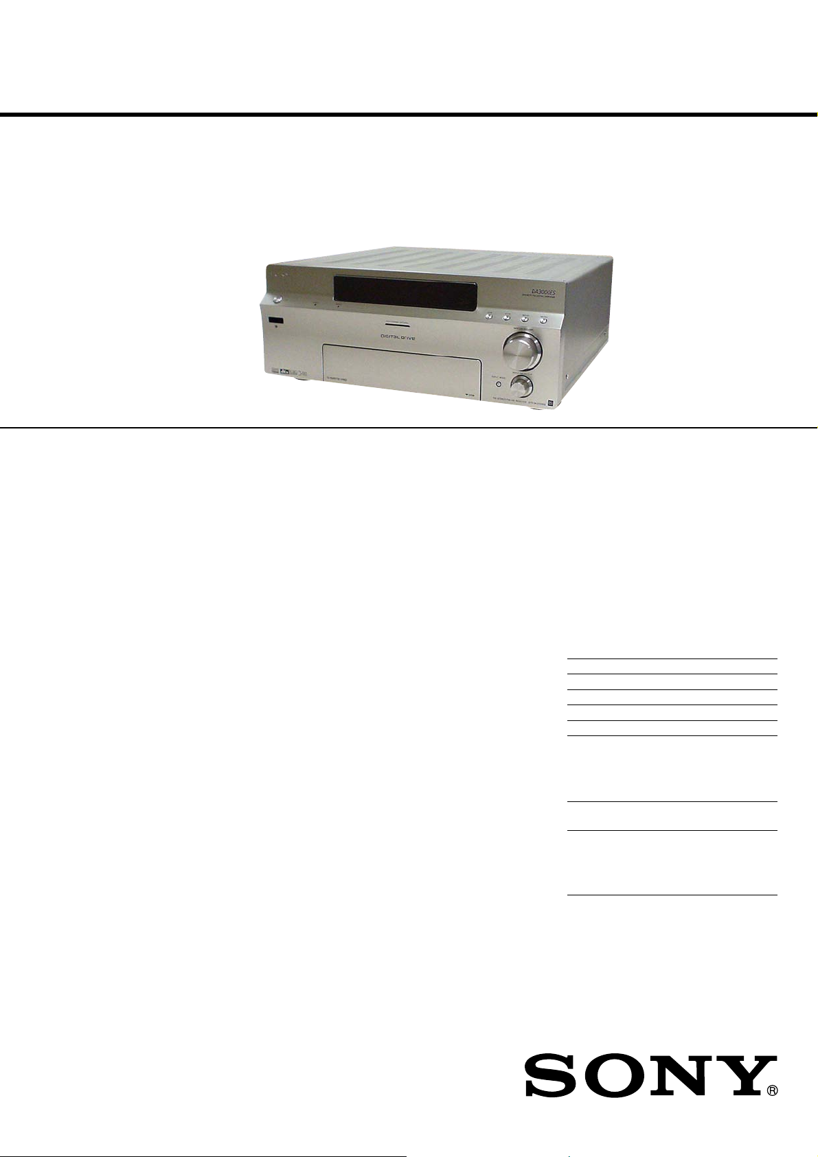
STR-DA3000ES
SERVICE MANUAL
Ver. 1.2 2005.07
This receiver incorporates Dolby* Digital and Pro
Logic Surround and the DTS** Digital Surround
System.
*Manufactured under license from Dolby
Laboratories.
“Dolby”, “Pro Logic” and the double-D symbol are
trademarks of Dolby Laboratories.
** “DTS”, “DTS-ES Extended Surround”, and
“Neo:6” are trademarks of Digital Theater Systems,
Inc.
US Model
Canadian Model
AEP Model
E Model
AUDIO POWER SPECIFICATIONS
POWER OUTPUT AND TOTAL HARMONIC
DISTORTION:
(Models of area code US only)
With 8 ohm loads, both channels driven, from 20
– 20,000 Hz; rated 150 watts per channel
minimum RMS power, with no more than 0.6%
total harmonic distortion from 250 milliwatts to
rated output.
Amplifier section
Models of area code US, Canadian, Taiwan:
POWER OUTPUT
Rated Power Output at Stereo Mode
(8 ohms 20 Hz – 20 kHz, THD 0.6%)
150 W + 150 W
Reference Power Output at Stereo Mode
(4 ohms 20 Hz – 20 kHz, THD 0.6%)
130 W + 130 W
Reference Power Output
(8 ohms 20 Hz – 20 kHz, THD 0.6%)
FRONT
CENTER
SURR
SURR BACK
150 W
SURR BACK
1)
2)
: 150 W + 150 W
2)
: 150 W
2)
: 150 W + 150 W
2)3)
: 150 W +
2)4)
: 150 W
SPECIFICATIONS
(4 ohms 20 Hz – 20 kHz, THD 0.6%)
Models of area code AEP, Korean:
POWER OUTPUT
Rated Power Output at Stereo Mode
(8 ohms 1 kHz, THD 0.7%)
Reference Power Output at Stereo Mode
(4 ohms 1 kHz, THD 0.7%)
Reference Power Output
(8 ohms 1 kHz, THD 0.7%)
(4 ohms 1 kHz, THD 0.7%)
2)
FRONT
: 130 W + 130 W
2)
CENTER
SURR
SURR BACK
130 W
SURR BACK
150 W + 150 W
130 W + 130 W
FRONT
CENTER
SURR
SURR BACK
FRONT
CENTER
SURR
SURR BACK
: 130 W
2)
: 130 W + 130 W
1)
2)
: 150 W + 150 W
2)
: 150 W
2)
: 150 W + 150 W
2)
: 130 W + 130 W
2)
: 130 W
2)
: 130 W + 130 W
2)3)
: 130 W +
2)4)
: 130 W
2)
: 150 W
2)
: 130 W
1) Depending on the sound field settings and the
source, there may be no sound output.
2) Measured under the following conditions:
Area code Power requirements
US, Canadian 120 V AC, 60 Hz
Taiwan 110 V AC, 60 Hz
AEP 230 V AC, 50/60 Hz
Korean 220 V AC, 60 Hz
3) Models of area code US, Canadian only.
4) Models of area code Taiwan only.
Frequency response
PHONO RIAA equalization curve
MULTI CHANNEL
INPUT 1, 2, CD/
SACD, TAPE, MD/
DAT, DVD, TV/SAT,
VIDEO 1, 2, 3
±0.5 dB
10 Hz – 40 kHz
±3 dB (wh en sound field and
equalizer bypassed)
– Continued on next page –
9-961-109-03 Sony Corporation
2005G05-1 Audio Group
© 2005.07 Published by Sony Engineering Corporation
FM STEREO FM/AM RECEIVER
Page 2
STR-DA3000ES
Inputs (Analog)
PHONO S/N: 86 dB
MULTI CHANNEL
INPUT 1, 2, CD/
SACD, TAPE, MD/
DAT, DVD, TV/SAT,
VIDEO 1, 2, 3
Inputs (Digital)
CD/SACD, DVD
(Coaxial)
CD/SACD, DVD, TV/
SAT, MD/DAT,
VIDEO3 (Optical)
Outputs
TAPE, MD/DAT
(REC OUT), VIDEO
1, 2 (AUDIO OUT)
FRONT L/R,
CENTER,
SURROUND L/R,
SURROUND BACK
(L/R), SUB WOOFER
EQUALIZER
Gain levels ±10 dB, 1 dB step
S/N: 96 dB
S/N: 96 dB
(A, 20 kHz LPF)
S/N: 96 dB
(A, 20 kHz LPF)
FM tuner section
Tuning range 87.5 - 108.0 MHz
Antenna FM wire antenna
Antenna terminals 75 ohms, unbalanced
Sensitivity
Mono: 18.3 dBf, 2.2 µV/75 ohms
Stereo: 38.3 dBf, 22.5 µV/75 ohms
Useable sensitivity 1
S/N
Mono:
Stereo:
Harmonic distortion at 1 kHz
Mono: 0.3%
Stereo: 0.5%
Separation 45 dB at 1 kHz
Frequency response 30 Hz – 15 kHz,
Selectivity 60 dB at 400 kHz
1.2 dBf, 1 µV/75 ohms
76 dB
70 dB
+0.5/–2 dB
AM tuner section
Tuning range
Models of area code U, CA:
530 – 1,710 kHz
(With 10-kHz tuning scale)
531 – 1,710 kHz
(With 9-kHz tuning scale)
Models of other area codes:
531 – 1,602 kHz
(With 9-kHz tuning scale)
Antenna Loop antenna
Usable sensitivity 50 dB/m (at 1,000 kHz or 999
kHz)
S/N 54 dB (at 50 mV/m)
Harmonic distortion 0.5% (50 mV/m, 400 Hz)
Selectivity
At 9 kHz: 35 dB
At 10 kHz: 40 dB
5) You can change the AM tuning scale to 9 kHz or 10
kHz. After tuning in any AM station, turn off the
receiver. While holding down PRESET TUNING +
or TUNING +, press ?/1. All preset stations will be
erased when you change the tuning scale. To reset
the scale to 10 kHz (or 9 kHz), repeat the procedure.
7)
7)
Video section
Inputs/Outputs
Video: 1 Vp-p, 75 ohms
S-video: Y: 1 Vp-p, 75 ohms
COMPONENT VIDEO:Y: 1 Vp-p, 75 ohms
C: 0.286 Vp-p, 75 ohms
/B-Y: 0.7 Vp-p, 75
P
B/CB
ohms
P
/R-Y: 0.7 Vp-p, 75
R/CR
ohms
General
Power requirements
Area code Power requirements
US, Canadian 120 V AC, 60 Hz
AEP 230 V AC, 50/60 Hz
Taiwan 110 V AC, 60 Hz
Korean 220 V AC, 60 Hz
Power consumption
Area code Power consumption
Except Canadian 280 W
Canadian 470 VA
Power consumption (during standby mode)
1 W
AC outlets
Area code AC outlets
US, Canadian 2 switched, 120 W/1A MAX
AEP 1 switched, 100 W MAX
Taiwan 2 switched, 100 W MAX
Korean – (no AC outlet)
Dimensions 430 × 175 × 470 mm
including projecting parts and
controls
Mass (Approx.) 13 kg
Supplied accessories
FM wire antenna (1)
AM loop antenna (1)
AC power cord (1)
Remote commander RM-LG112 (1)
R6 (size-AA) batteries (2)
Remote commander RM-US106 (1)
(US, Canadian models)
R6 (size-AA) batteries (2) (US, Canadian models)
Design and specifications are subject to change
without notice.
2
Page 3
STR-DA3000ES
Notes on chip component replacement
•Never reuse a disconnected chip component.
• Notice that the minus side of a tantalum capacitor may be damaged by heat.
SAFETY CHECK-OUT
After correcting the original service problem, perform the following safety check before releasing the set to the customer:
Check the antenna terminals, metal trim, “metallized” knobs,
screws, and all other exposed metal parts for AC leakage.
Check leakage as described below.
LEAKAGE TEST
The AC leakage from any exposed metal part to earth ground and
from all exposed metal parts to any exposed metal part having a
return to chassis, must not exceed 0.5 mA (500 microamperes.).
Leakage current can be measured by any one of three methods.
1. A commercial leakage tester , such as the Simpson 229 or RCA
WT -540A. Follo w the manufacturers’ instructions to use these
instruments.
2. A battery-operated AC milliammeter. The Data Precision 245
digital multimeter is suitable for this job.
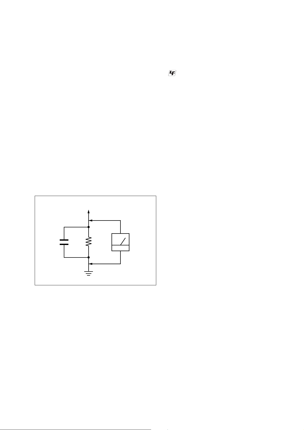
3. Measuring the v oltage drop across a resistor by means of a V OM
or battery-operated A C voltmeter . The “limit” indication is 0.75
V, so analog meters must have an accurate low-voltage scale.
The Simpson 250 and Sanwa SH-63Trd are examples of a passive VOM that is suitable. Nearly all battery operated digital
multimeters that have a 2 V A C range are suitable. (See Fig. A)
UNLEADED SOLDER
Boards requiring use of unleaded solder are printed with the leadfree mark (LF) indicating the solder contains no lead.
(Caution: Some printed circuit boards may not come printed with
the lead free mark due to their particular size)
: LEAD FREE MARK
Unleaded solder has the following characteristics.
• Unleaded solder melts at a temperature about 40 ˚C higher than
ordinary solder.
Ordinary soldering irons can be used but the iron tip has to be
applied to the solder joint for a slightly longer time.
Soldering irons using a temperature regulator should be set to
about 350 ˚C.
Caution: The printed pattern (copper foil) may peel away if the
heated tip is applied for too long, so be careful!
• Strong viscosity
Unleaded solder is more viscou-s (sticky, less prone to flow)
than ordinary solder so use caution not to let solder bridges occur such as on IC pins, etc.
• Usable with ordinary solder
It is best to use only unleaded solder but unleaded solder may
also be added to ordinary solder.
To Exposed Metal
Parts on Set
1.5 k
0.15 µF
Fig. A. Using an AC voltmeter to check AC leakage.
Ω
Earth Ground
AC
voltmeter
(0.75 V)
SAFETY-RELATED COMPONENT WARNING!!
COMPONENTS IDENTIFIED BY MARK 0 OR DOTTED
LINE WITH MARK 0 ON THE SCHEMATIC DIA GRAMS
AND IN THE PARTS LIST ARE CRITICAL TO SAFE
OPERATION. REPLACE THESE COMPONENTS WITH
SONY PARTS WHOSE PART NUMBERS APPEAR AS
SHOWN IN THIS MANU AL OR IN SUPPLEMENTS PUBLISHED BY SONY.
ATTENTION AU COMPOSANT AYANT RAPPORT
À LA SÉCURITÉ!
LES COMPOSANTS IDENTIFIÉS P AR UNE MARQUE 0
SUR LES DIAGRAMMES SCHÉMATIQUES ET LA LISTE
DES PIÈCES SONT CRITIQUES POUR LA SÉCURITÉ
DE FONCTIONNEMENT. NE REMPLACER CES COMPOSANTS QUE PAR DES PIÈCES SONY DONT LES
NUMÉROS SONT DONNÉS DANS CE MANUEL OU
DANS LES SUPPLÉMENTS PUBLIÉS PAR SONY.
3
Page 4

STR-DA3000ES
TABLE OF CONTENTS
1. SERVICING NOTES............................................... 5
2. GENERAL
Location of Controls ....................................................... 10
3. DISASSEMBLY
3-1. Disassembly Flow ........................................................... 11
3-2. Case ................................................................................. 11
3-3. Front Panel Section ......................................................... 12
3-4. D-AMP Board ................................................................. 13
4. TEST MODE .............................................................. 14
5. ELECTRICAL ADJUSTMENTS......................... 15
6. DIAGRAMS
6-1. Block Diagram – AUDIO IN Section – ......................... 19
6-2. Block Diagram
– ELECTRICAL VOLUME Section – ........................... 20
6-3. Block Diagram – DIGITAL 1 Section –........................ 21
6-4. Block Diagram – DIGITAL 2 Section –........................ 22
6-5. Block Diagram – DIGITAL 3 Section –........................ 23
6-6. Block Diagram – PRE OUT Section – .......................... 24
6-7. Block Diagram – POWER AMP Section – ................... 25
6-8. Block Diagram – VIDEO IN Section – ......................... 26
6-9. Block Diagram – CIS/DISPLAY Section –................... 27
6-10. Block Diagram – POWER SUPPLY Section –............. 28
6-11. Note for Printed Wiring Boards
and Schematic Diagrams ................................................ 29
6-12. Printed Wiring Board
– AUDIO Board (Component Side) – ............................ 30
6-13. Printed Wiring Board
– AUDIO Board (Conductor Side) – .............................. 31
6-14. Schematic Diagram – AUDIO Board (1/4) – ................ 32
6-15. Schematic Diagram – AUDIO Board (2/4) – ................ 33
6-16. Schematic Diagram – AUDIO Board (3/4) – ................ 34
6-17. Schematic Diagram – AUDIO Board (4/4) – ................ 35
6-18. Printed Wiring Board – ANALOG SUB Board – ......... 36
6-19. Schematic Diagram – ANALOG SUB Board – ............ 37
6-20. Schematic Diagram – DIGITAL Board (1/8) –............. 38
6-21. Schematic Diagram – DIGITAL Board (2/8) –............. 39
6-22. Schematic Diagram – DIGITAL Board (3/8) –............. 40
6-23. Schematic Diagram – DIGITAL Board (4/8) –............. 41
6-24. Schematic Diagram – DIGITAL Board (5/8) –............. 42
6-25. Schematic Diagram – DIGITAL Board (6/8) –............. 43
6-26. Schematic Diagram – DIGITAL Board (7/8) –............. 44
6-27. Schematic Diagram – DIGITAL Board (8/8) –............. 45
6-28. Printed Wiring Board
– DIGITAL Board (Component Side) – ......................... 46
6-29. Printed Wiring Board
– DIGITAL Board (Conductor Side) –........................... 47
6-30. Printed Wiring Board
– D-AMP Section (Component Side) –.......................... 48
6-31. Printed Wiring Boards
– D-AMP Section (Conductor Side) – ........................... 49
6-32. Schematic Diagram – D-AMP Section (1/6) – ............. 50
6-33. Schematic Diagram – D-AMP Section (2/6) – ............. 51
6-34. Schematic Diagram – D-AMP Section (3/6) – ............. 52
6-35. Schematic Diagram – D-AMP Section (4/6) – ............. 53
6-36. Schematic Diagram – D-AMP Section (5/6) – ............. 54
6-37. Schematic Diagram – D-AMP Section (6/6) – ............. 55
6-38. Printed Wiring Board
– PRE-OUT Board (Component Side) –
(US, CND models) .......................................................... 56
6-39. Printed Wiring Board
– PRE-OUT Board (Conductor Side) –
(US, CND models) .......................................................... 57
6-40. Schematic Diagram – PRE-OUT Board –
(US, CND models) .......................................................... 58
6-41. Schematic Diagram – VIDEO Board (1/3) – ................ 59
6-42. Schematic Diagram – VIDEO Board (2/3) – ................ 60
6-43. Schematic Diagram – VIDEO Board (3/3) – ................ 61
6-44. Printed Wiring Board
– VIDEO Board (Component Side) –............................. 62
6-45. Printed Wiring Board
– VIDEO Board (Conductor Side) – .............................. 63
6-46. Printed Wiring Board – S-VIDEO Board –................... 64
6-47. Schematic Diagram – S-VIDEO Board –...................... 65
6-48. Printed Wiring Board – CIS Board –
(US, CND models) .......................................................... 66
6-49. Schematic Diagram – CIS Board –
(US, CND models) .......................................................... 67
6-50. Printed Wiring Board – FL Board – .............................. 68
6-51. Schematic Diagram – FL Board – ................................. 69
6-52. Printed Wiring Boards – PANEL Section – .................. 70
6-53. Schematic Diagram – PANEL Section –....................... 71
6-54. Printed Wiring Board
– REG Section (Component Side) –............................... 72
6-55. Printed Wiring Boards
– REG Section (Conductor Side) – ................................ 73
6-56. Schematic Diagram – REG Section (1/2) – .................. 74
6-57. Schematic Diagram – REG Section (2/2) – .................. 75
6-58. IC Pin Function Description ........................................... 92
7. EXPLODED VIEWS
7-1. Case Section ................................................................... 109
7-2. Front Panel Section-1..................................................... 110
7-3. Front Panel Section-2..................................................... 111
7-4. Chassis Section-1 ........................................................... 112
7-5. Chassis Section-2 ........................................................... 113
7-6. Chassis Section-3 ........................................................... 114
7-7. Chassis Section-4 ........................................................... 115
7-8. Chassis Section-5 ........................................................... 116
7-9. REG Board Section........................................................ 117
7-10. D-AMP Board Section................................................... 118
8. ELECTRICAL PARTS LIST ..............................119
4
Page 5
SERVICING NOTES
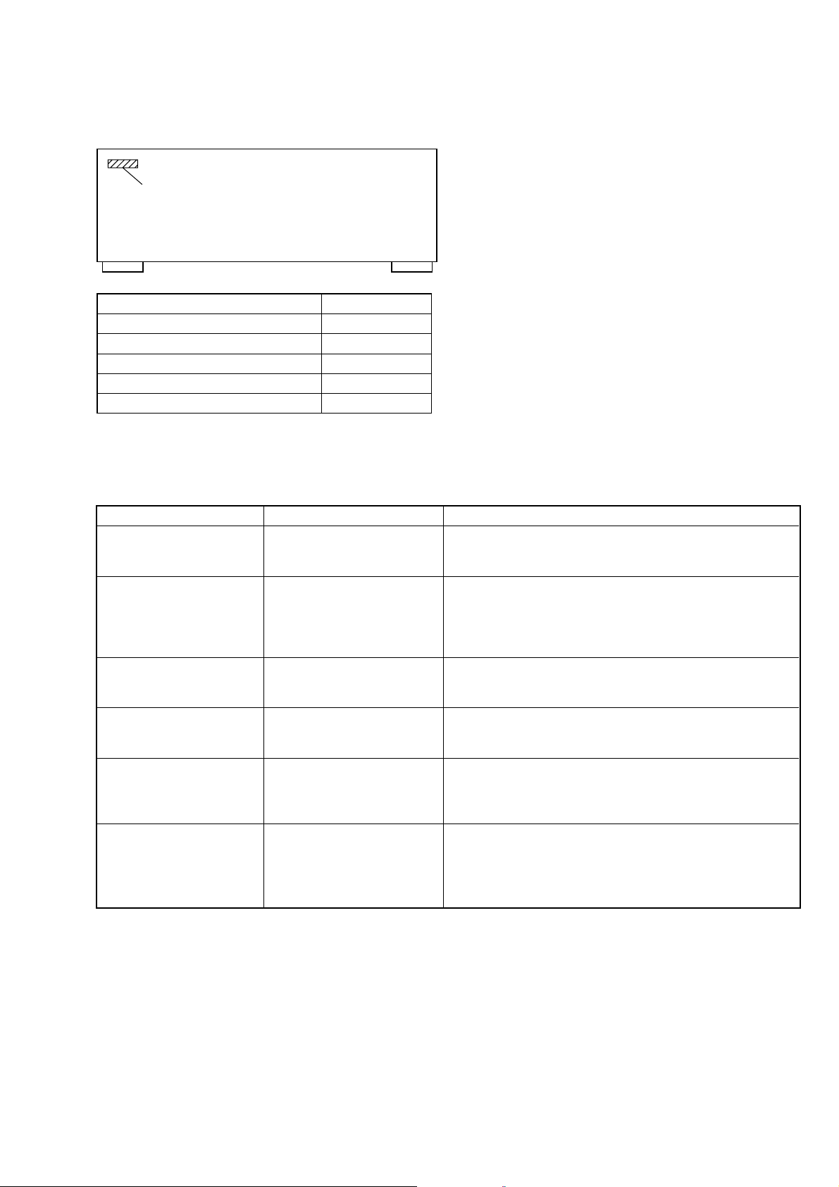
• MODEL IDENTIFICATION
– Back Panel –
PART No.
Model PART No.
US model 4-246-512-0
Canadian model 4-246-512-1
AEP model 4-246-512-2
Taiwan model 4-246-512-3
Korean model 4-246-512-4
SECTION 1
[]
[]
[]
[]
[]
STR-DA3000ES
Ver 1.1
ERROR MESSAGES
If there is a malfunction, the display shows a code of two numbers and a message. You can check the condition of the system by message.
Refer to the following table to solve the problem.
messages check code cause and response
DECODE ERROR 01 Appears when the signal which the receiver can not decode
(example DSD-CD) is input when “DEC. PRI.” in the CUSTOM
IZE menu is set to “PCM”. Set to “AUTO”.
PROTECTOR 11 Irregular current output to the speakers. Turn off the receiver and
check the speaker connection. Then turn on the power again. Be
comes this display, When short current flowed with breakage of
the power MOS, or when detection resistor becomes open in
connection with it.
PROTECTOR 12 The amplifier section is overheated. Turn off the receiver and
check that the ventilation hole is not covered. Leave the receiver
for a while and turn on the power again.
PROTECTOR 13 The power supply section is overheated. Turn off the receiver and
check that the ventilation hole is not covered. leave the receiver
for a while and turn on the power again.
PROTECTOR 21 DC between speaker terminal is detected (abnomalities such as
DSD 0DATA and signal clip can be considered). Turn off the
receiver and check the speaker connection. Then turn on the power
again.
PROTECTOR 22 Two defects a e considered, when current detection of a switching
power supply operated by the super fluous speaker, +B power
supply shut down or when the power MOS broke and +B line
short. Turn off the receiver and check the speaker connection.
Then turn on the power again.
5
Page 6
STR-DA3000ES
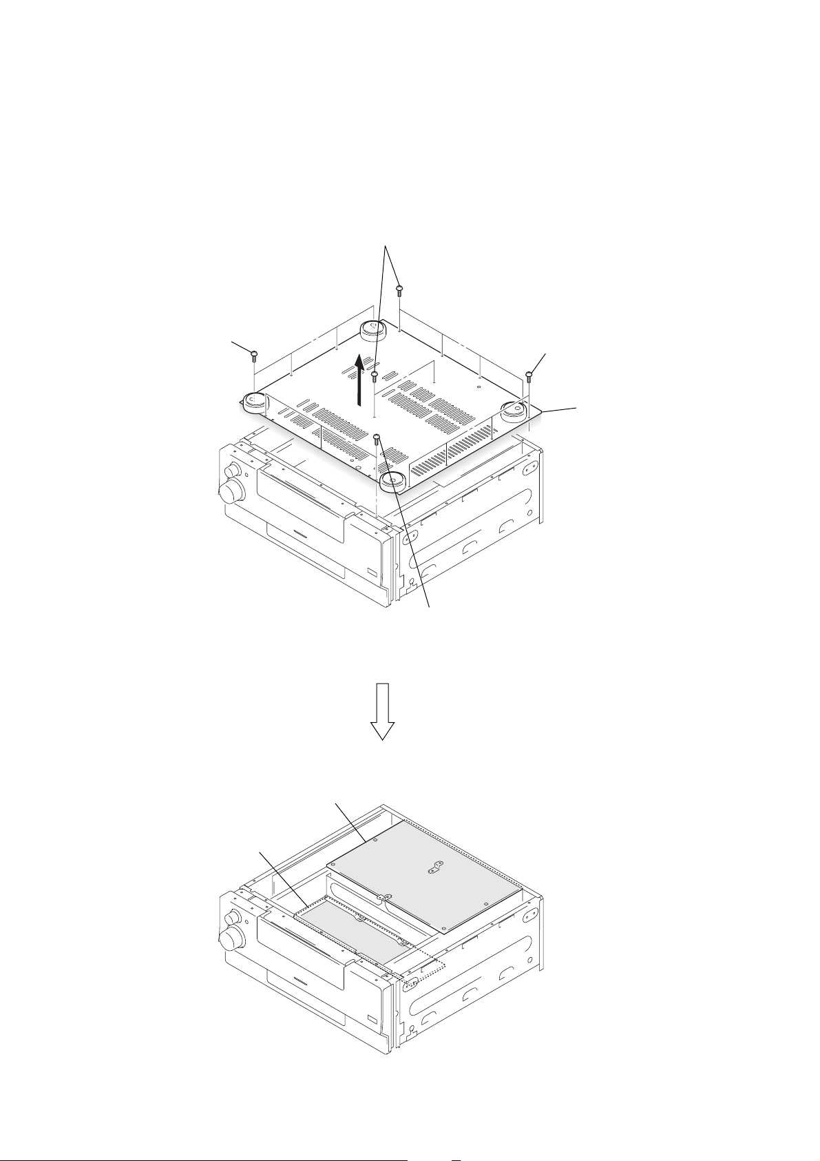
Note: Follow the disassembly procedure in the numerical order given.
D-AMP BOARD, REG BOARD SERVICE POSITION
– BOTTOM VIEW –
1
four screws
(BVTP3
×
8)
1
six screws
(BVTP3
×
8)
1
four screws
(BVTP3
×
8)
2
bottom plate
REG board
D-AMP board
1
three screws
(BVTP3
×
8)
6
Page 7
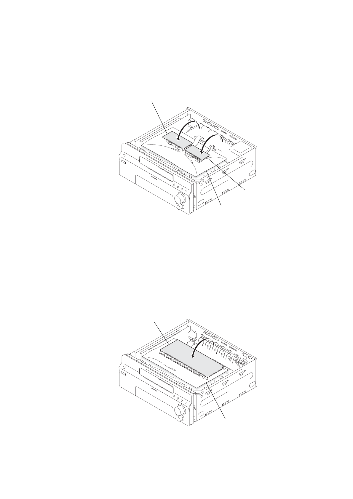
CIS BOARD (US, Canadian models), S-VIDEO BOARD SERVICE POSITION
S-video board
STR-DA3000ES
VIDEO BOARD SERVICE POSITION
CIS board
(US, Canadian models)
insulator
video board
insulator
7
Page 8

STR-DA3000ES
AUDIO BOARD SERVICE POSITION
audio board
SWITCHING REGULATOR SERVICE POSITION
insulator
switching regulator
8
Page 9

STR-DA3000ES
digital board
Connect jig (extension cable J-2501-252-A)
to the D-AMP board (CN1901)
and digital board (CN2004).
D-AMP board
(CN1901)
DIGITAL BOARD SERVICE POSITION
In checking the digital board, prepare jig (extension cable J-2501-252-A: 1.25 mm Pitch, 35 cores, Length 300 mm).
CAUTIONS OF THE ATTACHMENT SCREW BUNDLE OF AUDIO BOARD
Note: Since the ground is concentrating here,
be careful especially in the case of a screw stop,
and tighten a screw firmly.
audio board
9
Page 10

STR-DA3000ES
LOCATION OF CONTROLS
– Front Panel –
Main unit
SECTION 2
GENERAL
This section is extracted from
instruction manual.
ALPHABETICAL ORDER
A.F.D. 6
BASS es
DECODE PRIORITY wd
Digital Cinema Sound indicator
4
DIMMER indicator qd
DIRECT wf
DIRECT indicator 2
DISPLAY ws
Display 3
FM/AM ql
INPUT MODE qa
INPUT SELECTOR 0
IR receptor qf
MAIN MENU e;
MASTER VOLUME 9
MEMORY/ENTER w;
MENU wl
MOVIE 7
MULTI CH IN 1/2 wg
MULTI CHANNEL DECODING
indicator qs
MUSIC 8
PHONES jack qg
PRESET TUNING –/+ qj
SPEAKERS switch qh
SURR BACK DECODING wh
TREBLE ea
TUNING –/+ qk
USER PRESET wa
VIDEO 3 INPUT jacks wj
NUMBERS AND SYMBOLS
2CH 5
?/1 (power) 1
–/+ wk
1 2 3 4 65 7 8
qsqf 0qa
qd
v
qkqjqhqg ql w; wa ws wd
wf wg wh
9
10
ea e; wl
es
wk
wj
Page 11

1
two flat head screws
2
2
1
two flat head screws
1
two flat head screws
3
case
• This set can be disassembled in the order shown below.
3-1. DISASSEMBLY FLOW
SET
3-2. CASE
(Page 11)
STR-DA3000ES
SECTION 3
DISASSEMBLY
3-3. FRONT PANEL SECTION
(Page 12)
Note: Follow the disassembly procedure in the numerical order given.
3-4. D-AMP BOARD
(Page 13)
3-2. CASE
11
Page 12

STR-DA3000ES
3-3. FRONT PANEL SECTION
3
4
bracket (panel)
screw
(BVTP3
×
8)
4
bracket (panel)
3
screw
(BVTP3
×
8)
1
wire (flat type) (17 core)
(CN2007)
2
wire (flat type) (23 core)
(CN2008)
8
5
screw
(BVTP3
seven screws
(BV/RING)
×
8)
9
ground wire
7
connector
(CN1012)
5
screw (BV/RING)
9
ground wire
12
0
front panel section
6
8
screw
(BVTP3
×
8)
Page 13

3-4. D-AMP BOARD
7
four screws
(BVTP3
×
8)
7
four screws
(BVTP3
×
8)
7
six screws
(BVTP3
×
8)
7
three screws
(BVTP3
×
8)
8
bottom plate
3
three connectors
(CN3, CN903, CN1480)
4
two screws
(PSW3
×
8)
5
two ground wires
6
Turn over the set.
1
2
STR-DA3000ES
wire (flat type) (25 core)
(CN1902)
wire (flat type) (35 core)
(CN1901)
9
six screws
(BV/RING)
9
screw (BV/RING)
(US, Canadian models)
0
qa
qd
D-AMP board
qs
connector
(CN1853)
13
Page 14

STR-DA3000ES
Ver 1.1
SECTION 4
TEST MODE
TUNER FACTORY PRESET MODE
All preset contents are reset to the default setting.
Procedure:
1. While pressing the [SURR BACK DECODING] and [PRE-
SET TUNING --] buttons, press the I/1 button to turn on the
main power.
2. The message “TUNER FACTOR Y PRESET” appears and the
present contents are reset to the default values.
TUNER AM STEP CHANGE (9 kHz/10 kHz) MODE
Either the 9 kHz step or 10 kHz step can be selected for the AM
channel step.
Procedure:
1. While pressing the [PRESET TUNING +] or [DISPLAY] button, press the I/1 button to turn on the main power.
2. Either the message “AM 9K STEP” or “AM 10K STEP” appears. Select the desired step.
TUNER AUTOBETICAL TUNING MODE
Procedure:
1. While pressing the [MEMORY/ENTER] button, press the
I/1 button to turn on the main power.
2. The message “Autobetical select” appears and scans and stores
all the FM and FM RDS stations in the broadcast area.
3. When done, the message “FINISH” appears.
SOUND FIELD CLEAR MODE
The preset sound field is cleared when this mode is activated. Use
this mode before returning the product to clients upon completion
of repair.
Procedure:
1. While pressing the [MUSIC] button, press the I/1 button to
turn on the main power.
2. The message “S. F. Initialize” appears and initialization is performed.
FLUORESCENT INDICATOR TUBE PATTERN
CHECK MODE
All fluorescent segments are tested. When this test is acti vated, all
segments turn on at the same time, then each segment turns on one
after another.
Procedure:
1. While pressing the [DISPLAY] and [MEMORY/ENTER] buttons, press the I/1 button to turn on the main power.
2. All se gments and [MULTI CHANNEL DECODING] indicator
LED turn on.
COMMAND MODE CHANGE MODE
The command mode of the remote-commander which this set receives can be changed.
Procedure:
1. While pressing the [INPUT MODE] button, press the I/1 button to turn on the main power.
2. Either the message “COMMAND MODE [AV1]” or “COMMAND MODE [AV2]” appears. Select the desired mode.
SF LOCK ON/OFF CHANGE MODE
Procedure:
1. While pressing the [MUSIC] and [MEMORY/CLEAR] buttons,
press the I/1 button to turn on the main power.
2. Either the message “SF LOCK [OFF]” or “SF LOCK [ON]”
appears.
SPECIAL MENU MODE
About the special menu mode, refer to SUPPLEMENT-1.
ALL CLEAR MODE
All preset contents are cleared when this mode is activated. Use
this mode before returning the product to clients upon completion
of repair.
Procedure:
1. While pressing the [INPUT MODE] and [MEMORY/ENTER]
buttons, press the I/1 button to turn on the main power.
2. The message “MEMORY CLEARING...” appears and the
memories are reset to the default values.
3. When done, the message “MEMORY CLEARED!” appears.
VOLUME CHECK MODE
Procedure:
1. While pressing the [2CH] and [MEMORY/ENTER] buttons,
press the I/1 button to turn on the main power.
2. Press the [DISPLAY] button.
3. The message “–oodB” appears. (Volume level is “MIN”)
4. Press the [DISPLAY] button once again.
5. The message “–57.5dB” appears. (Volume level is “MID”)
6. Press the [DISPLAY] button once again.
7. The message “0.0dB” appears. (Volume level is “MAX”)
8. Press the [DISPLAY] button once again.
9. The message “MUTING” appears. (Muting on)
10. Press the [DISPLAY] button once again.
11. The message “MUTING OFF” appears. (Muting off)
14
Page 15

SECTION 5
ELECTRICAL ADJUSTMENTS
DC OFFSET ADJUSTMENT
Condition:
function: MULTI CH 2
input signal: no signal (no load)
volume: 0 dB
Connection
digital voltmeter
3
+40
–0
mV)
pin,
+
#
pin,
–
2
TM1710 (TM1730, 1740, 1750, 1760, 1770)
TM1710 (TM1730, 1740, 1750, 1760, 1770)
CN919 pin
3
C941
1
(US, Canadian models) or
pin (except US, Canadian models)
CN919 pin
Procedure:
1. Connect a digital voltmeter to the TM1710 (TM1730, 1740,
1750, 1760, 1770) on the D-AMP board, CN919 (US, Canadian
models) and C941 (except US, Canadian models) on the REG
board.
2. Press the I/1 button to turn on the main power.
3. Adjust the RV111 (141, 161, 181, 211, 241, 261, 281) so that
the digital voltmeter reading is ±20 mV. (Only adjustment use
RV261, digital voltmeter reading is
STR-DA3000ES
Adjustment and Connection Location: see page 16
15
Page 16

STR-DA3000ES
Adjustment and Connection Location:
– ANALOG SUB BOARD (Component Side) –
RV111
RV211
– D-AMP BOARD (Conductor Side) –
RV141
RV241
RV161 RV261
RV181 RV281
Front
Speaker
L-ch
+
–+
Front
Speaker
R-ch
– REG BOARD (Conductor Side) –
Center
Speaker
–
+
C941
CN919
12
Surround
Speaker
L-ch
+
–
+
–
Surround
Speaker
R-ch
+
–
Surround back
Speaker
L-ch
+
–
Surround back
Speaker
R-ch
+
–
16
Page 17

OSD ADJUSTMENT
Connection
STR-DA3000ES
frequency counter
VIDEO board
TP3501 pin
1
or pin
2
+
–
1. Short the TP3501 pin 4 on the VIDEO board to the GND.
2. Connect a frequency counter to the TP3501 pin 2 on the VIDEO
board.
3. Press the I/1 button to turn on the main power.
4. Press the [ON SCREEN] button on the remote commander.
5. Turn the [MAIN MENU] jog to display “CUSTOMIZE”.
6. Turn the [MENU] jog to display “COLOR SYSTEM”.
7. Turn the [--/+] jog to display “NTSC”.
8. Adjust the CT3502 (except AEP model) or CT3503 (AEP
model) so that the frequency counter reading is 3.579545±0.05
MHz.
9. Turn the [MENU] jog to display “COLOR SYSTEM”.
10. Turn the [--/+] jog to display “PAL”.
11. Press the [ON SCREEN] button on the remote commander.
12. Adjust the CT3504 so that the frequency counter reading is
4.433618±0.05 MHz.
13. Press the I/1 button to turn off the main power.
14. Connect a frequency counter to the CN3501 pin 1 on the
VIDEO board.
15. Press the I/1 button to turn on the main power.
16. Press the [ON SCREEN] button on the remote commander.
17. Adjust the CT3501 so that the frequency counter reading is
7.20±0.01 MHz.
Note: The steps 5 to 7 and 9 to 12 should be performed to AEP model.
Adjustment and Connection Location:
– VIDEO BOARD (Component Side) –
CT3503
(AEP model)
CT3501
CT3504
(AEP model)
CT3502
(except AEP model)
TP3501
1
4
17
Page 18

STR-DA3000ES
UP CONVERT SIGNAL LEVEL ADJUSTMENT
Enter the test mode
1. In the standby status, press the I/1 button while pressing the
[INPUT MODE] and [DISPLAY] buttons.
2. It enters the test mode, and display as below figure.
Display
HUE
[7]
1. Y Level Adjustment
Setting:
VIDEO 1
S2 VIDEO IN jack
color pattern
generator
color bars 100%
Procedure:
1. Connect a color pattern generator to the VIDEO 1 S2 VIDEO
IN jack, and connect an oscilloscope to the COMPONENT
VIDEO Y jack.
2. Enter the test mode.
3. Input color bars signal from the color pattern generator.
4. Adjust the [MENU] knob so that the Vp-p value of waveform
becomes 1 Vp-p.
Y waveform:
CONTRAST
[7]
COMPONENT
VIDEO Y jack
set
COLOR
[7]
oscilloscope
(AC range)
+
–
2. Color Level Adjustment
Setting:
VIDEO 1
S2 VIDEO IN jack
color pattern
generator
color bars 100%
COMPONENT VIDEO
R/CR
P
COMPONENT VIDEO
P
B/CB
/B-Y jack
set
/R-Y jack
oscilloscope
(AC range)
+
–
Procedure:
1. Connect a color pattern generator to the VIDEO 1 S2 VIDEO
IN jack, and connect an oscilloscope to the COMPONENT
VIDEO P
/B-Y jack and COMPONENT VIDEO PR/CR/R-
B/CB
Y jack.
2. Enter the test mode.
3. Input color bars signal from the color pattern generator.
4. Display two w aveforms of CB and CR simultaneously.
5. Adjust the [--/+] knob so that the Vp-p value of waveforms of
CB and CR both may be most set to 0.7V closely.
B
waveform:
C
0.7 Vp-p
R
waveform:
C
1 Vp-p
0.7 Vp-p
3. HUE Level Adjustment
Setting:
VIDEO 1
S2 VIDEO IN jack
color pattern
generator
color bars 100%
COMPONENT VIDEO
P
B/CB
/B-Y jack
set
oscilloscope
(AC range)
+
–
Procedure:
1. Connect a color pattern generator to the VIDEO 1 S2 VIDEO
IN jack, and connect an oscilloscope to the COMPONENT
VIDEO PB/CB/B-Y jack.
2. Enter the test mode.
3. Input color bars signal from the color pattern generator.
4. Adjust the [MAIN MENU] knob so that the waveform as bellow .
CB waveform:
B
A
18
Adjust so that the height of
A and B may be located in a line
on this line.
Page 19

STR-DA3000ES
SERVICE MANUAL
Ver 1.1 2004.09
SUPPLEMENT-1
Subject: Addition of “SPECIAL MENU MODE”
US Model
Canadian Model
AEP Model
E Model
9-961-109-81
Page 20

STR-DA3000ES
SPECIAL MENU MODE
Procedure:
1. Press the I/1 button to turn on the main power, then while pressing the [MEMORY/ENTER] button, press the [MOVIE] button in order.
2. The message “MENU EXPANDED !” appears.
3. Each time the [MENU] dial is turned clockwise, the item is switched in order as follows.
4. To release from this mode, while pressing the [MEMORY/ENTER] button, press the [MOVIE] button in order again.
5. The message “MENU EXPAND OFF” appears.
Items Display Remark
Protector on/off SPECIAL XXX: ON or OFF (switching with
PROTECTOR ON/OFF [XXX
Model version display SPECIAL ####: model
####
Model/distination change SPECIAL ####: model,
MODEL [
FL display fonts test SPECIAL
FL FONT 0x** = [X
FL display test ALL ON Each time
Audio swap SPECIAL Switching with
SWAP [XXXXXXXXXXX
DSP reset SPECIAL XXX: ON or OFF (switching with
DSP RESET [XXX
DSP 1 IRAM DSP 1 IRAM The umbers which can be changed will blinks
[
I
*****
DSP 1 ARAM DSP 1 ARAM The umbers which can be changed will blinks
[
D
*****
DSP 2 IRAM DSP 2 IRAM The umbers which can be changed will blinks
[
I
*****
vX.XX @@@@
****
####
]=
]=
]=
****
] Note: Since it continues being reset when “DSP RESET [ON]”
XXXX To select the digit: Press the [TUNING +] or [TUNING --] button
XXXXXXXX To select the digit: Press the [TUNING +] or [TUNING --] button
XXXX To select the digit: Press the [TUNING +] or [TUNING --] button
]
: destination
****
X.XX: main microprocessor software version
@@@@: Sum value of flash memory in the main microprocessor
]
XX (switching with [--/+] dial)
: 20 to 1F, X: character (switching with [--/+] dial)
]
**
****
[DISPLAY] button to change as follows.
all on t test pattern 1 t test pattern 2 t all off t all on
[--/+] dial
]
is chosen, be sure to return to “DSP RESET [OFF]”
T o select the number when the umbers (
Rotate the [--/+] dial
To perform the write when the umbers (XXXX) blinks:
Press the
*****
XXXX: instruction RAM address data
Note: When parenthesis is the position of instruction RAM
T o select the number when the umbers (
blinks: Rotate the [--/+] dial
To perform the write when the umbers (XXXXXXXX) blinks:
Press the [MEMORY/ENTER] button
*****
XXXXXXXX: coefficient RAM address data
Note: When parenthesis is the position of
T o select the number when the umbers (
Rotate the [--/+] dial
To perform the write when the umbers (XXXX) blinks:
Press the [MEMORY/ENTER] button
*****
XXXX: instruction RAM address data
Note: When parenthesis is the position of instruction RAM
[MEMORY/ENTER] button
: instruction RAM address
address data, up/down of the menu item by
are invalid
: coefficient RAM address
address data, up/down of the menu item by
are invalid
: instruction RAM address
address data, up/down of the menu item by
are invalid
: destination, XX: at or fx
[--/+] dial)
[--/+] dial)
*****
*****
coefficient
*****
or XXXX) blinks:
the [MENU] dial
or XXXXXXXX)
RAM
the [MENU] dial
or XXXX) blinks:
the [MENU] dial
2
Page 21

STR-DA3000ES
Items Display Remark
DSP 2 ARAM DSP 2 ARAM The umbers which can be changed will blinks
[
D
*****
Bass management SPECIAL
BASSMAN. [
DSP boot error SPECIAL Not used for the servicing
DSP write 1 error SPECIAL Not used for the servicing
DSP write 2 error SPECIAL Not used for the servicing
DSP write 3 error SPECIAL Not used for the servicing
DSP read 1 error SPECIAL Not used for the servicing
DSP read 2 error SPECIAL Not used for the servicing
DSP read 3 error SPECIAL Not used for the servicing
DSP HALT SPECIAL XXX: ON or OFF (switching with
DSP HALT [XXX
DSP Version display SPECIAL Not used for the servicing
SurV *:vXXX
Volume value display SPECIAL Not used for the servicing
(FL/FR) FL
Volume value display SPECIAL Not used for the servicing
(SL/SR) SL
Volume value display SPECIAL Not used for the servicing
(CT/SW) CT
Volume value display SPECIAL Not used for the servicing
(SBL/SBR) SBL
EEPROM debug SPECIAL
EEPROM
Super reset SPECIAL Not used for the servicing
SUPER RESET [XXX
2nd volume value display SPECIAL XX: 2nd zone volume value (00 to
2nd VOLUME –XX (switching with [--/+] dial)
3rd volume value display SPECIAL XX: 3rd zone volume value (00 to
3rd VOLUME –XX (switching with [--/+] dial)
FL display duty change SPECIAL XXX: Duty value of FL display (0% to 100%)
DARK OUT DUTY [XXX%
SDRAM check SPECIAL Check the operation of LIP SYNC
SDRAM CHECK [XXXXX
Error count display SPECIAL Not used for the servicing
SCOM ERROR COUNT XXX
Version display SPECIAL Not used for the servicing
Sub Micom Ver. X.XX
]=
XXXXXXXX To select the digit: Press the [TUNING +] or [TUNING --] button
To select the number when the umbers (
blinks: Rotate the [--/+] dial
To perform the write when the umbers (XXXXXXXX) blinks:
Press the
*****
XXXXXXXX: coefficient RAM address data
Note: When parenthesis is the position of
] XX (switching with [--/+] dial)
****
****
DSP BOOT ERROR:XXX
DSP WRT1 ERROR:XXX
DSP WRT2 ERROR:XXX
DSP WRT3 ERROR:XXX
DSP RAD1 ERROR:XXX
DSP RAD2 ERROR:XXX
DSP RAD3 ERROR:XXX
[MEMORY/ENTER] button
: coefficient RAM address
address data, up/down of the menu item by
are invalid
: AUTO or OFF, XX: 02 to 30
*****
coefficient
[--/+] dial)
]
FR XXXX
****
SR XXXX
****
SW XXXX
****
SBR XXXX
****
: EEPROM address
[
****
]
XX XX: EEPROM data (switching with [--/+] dial)
]
****
If super reset is performed, “up convert signal level adjustment”
will also be initialized
When EEPROM initialization is required, perform the “all clear
mode” (see page 14 of original service manual)
)
∞
)
∞
]
(switching with [--/+] dial)
]
XXXXX: PASS (OK) or ERROR (NG)
or XXXXXXXX)
RAM
the [MENU] dial
3
Page 22

STR-DA3000ES
REVISION HISTORY
Clicking the version allows you to jump to the revised page.
Also, clicking the version at the upper right on the revised page allows you to jump to the next revised
page.
Ver. Date Description of Revision
1.0 2003.08 New
1.1 2004.09 Addition of “ERROR MESSAGES” to SERVICING NOTES.
Addition of “SPECIAL MENU MODE” (SUPPLEMENT-1)
(ENG-04006/SPM-04087)
1.2 2005.07 Change of Part No. for Ref. No. C1711, 1712, 1713, 1714, 1715, 1716,
1717, R1711, 1712, 1713, 1714, 1715, 1716, 1717 on D-AMP board
(SPM-05046)
 Loading...