

Page 1
ES Series Receivers
Technical Background
Version 3.0; May 30, 2003
Page 2

Introduction
For 2003, Sony is introducing a completely new and dramatically different
line of ES Series audio/video receivers. To create these remarkable
components, Sony ES engineers have rethought, refreshed and redesigned just
about every aspect:
• Digital power amplifier technology (STR-DA2000ES and higher)
• Redesigned internal chassis layout (STR-DA2000ES and higher)
• Pulse power supply (STR-DA2000ES, DA3000ES and DA5000ES)
• i.LINK® (IEEE 1394) 1-bit digital interface for Super Audio CD (STR-
DA9000ES)
• Superior ergonomics with "silver cascade" front panel (STR-DA3000ES and
higher)
While these design breakthroughs are exciting and fresh, the fact that they
make their appearance in the Sony ES Series should come as no surprise at all.
From the very beginning, ES receivers have benefited from Sony's
comprehensive expertise in digital source components and Sony's thorough
understanding of digital signals. Those insights led directly to significant Sony
ES innovations:
• The world's first outboard D/A converter (DAS-702ES, 1985).
• The world's first Dolby® Surround decoder to operate in the digital domain
(SDP-505ES, 1986).
• The world's first all-digital preamplifier (TA-E1000ESD, 1989).
• 24-bit Dolby Digital® decoding (SDP-EP9ES, 1997).
• Digital Cinema Sound™ processing (STR-DA90ESG, 1997).
• World's first floating-point 32-bit preamplifier (TA-E9000ES, 1998).
Sony's latest A/V receivers are worthy successors, carrying this heritage
forward to a new generation of home entertainment enthusiasts.
S-Master Pro Technologies................... Page 3
S-Master Pro Benefits....................... Page 15
Other New Features......................... Page 21
Continuing Features......................... Page 30
Features and Specifications.................... Page 32
ES Receivers V3.0 Page 2
Page 3

S-Master Pro Technologies
Digital amplifiers have been around for decades, occupying a place
outside the mainstream of home audio. But important trends in audio technology
are creating significant reasons to prefer digital amplification.
First, digital signal-handling technology has improved, especially in the
area of 1-bit digital signal processing. Modern circuitry can exercise amazingly
precise control over 1-bit pulse lengths, pulse height and pulse timing, for jitterfree, distortion-free performance. Large Scale Integrated (LSI) technology
continues to move forward, enabling manufacturers to build this sophisticated
technology into consumer products. Today's faster output transistors do a better
job at digital switching speeds. Finally, home entertainment continues to move
inexorably into the digital domain, leaving analog processes behind.
Simultaneous with these advances, the function of the home audio
receiver has been transformed. "High fidelity" or "AM/FM" receivers have long
since given way to sophisticated A/V control centers that first handled composite
video, then added component video, HD component video and now digital
component video. Over the years, stereo receivers have been transformed into
four, five, six and now seven-channel receivers. And the designs continue to
grow in complexity. In this new context, digital amplification is becoming more
and more compelling.
It was for this reason that Sony first developed the S-Master process back
in 2001. The 2003 ES receivers, starting with the STR-DA2000ES, incorporate
Sony's third generation of S-Master technology—and our most advanced by far.
Process S-Master "Digital Drive" S-
Master
Generation
Introduction
Technologies
First Second Third
2001 2002
AVD-C70ES
AVD-S50ES
• Clean Data Cycle
• C-PLM
• S-TACT
• Clean Data Cycle
• C-PLM
• S-TACT
• Pulse Height Volume
Control
S-Master Pro
2003
STR-DA9000ES
STR-DA5000ES
STR-DA3000ES
STR-DA2000ES
• Clean Data Cycle
• C-PLM
• S-TACT
• Pulse Height Volume
Control
• DC Phase Linearizer
• Discrete Output
Transistors
• Toroidal Low Pass Filter
• Two-Stage Pulse Power
Supply
ES Receivers V3.0 Page 3
Page 4

A look at analog amplifiers
Conventional, analog power amplifiers have awkward characteristics that
are so familiar that receiver engineers automatically work around them.
However, Sony's design program for the 2003 ES Series required more than the
typical work-around. We sought to address these issues directly:
• Circuit complexity. In the context of today's home theater receivers, the
analog power amplifier is out of place. You have digital source material
processed through a digital preamplifier—only to be converted to analog prior
to amplification.
• Heat generation. The heat thrown off by conventional power output
transistors is a central fact of amplifier and receiver design. Conventional
amplifiers and receivers often require heat sinks, fans, and chassis layouts
that isolate the output transistors at the back or sides. Heat is always bad for
electronics. Sony sought a more comprehensive solution for these ES
receivers.
• Crossover distortion. Conventional power amplifiers use complementary
pairs or sets of transistors to handle the top half and the bottom half of the
waveform. This can create crossover distortion, the solution to which is
amplifier bias—and that means more heat!
• Thermal modulation distortion. As the changing audio signal passes
through the typical output transistors, it causes immediate changes in the
transistors' temperature. Unfortunately, the temperature changes affect the
transistors' handling of audio signal. This is thermal modulation distortion.
Left unchecked, it can degrade sound quality.
• Open-loop distortion. Conventional amplifiers typically generate substantial
distortion in "open-loop" mode. That's why amplifiers correct this distortion
with Negative Feedback (NFB). However, NFB exposes the signal to
Transient Intermodulation Distortion and other dynamic problems.
Sony's design program for the 2003 ES receiver line overcomes these
fundamental constraints by applying digital technology.
S-Master Pro: simplicity of design
For years, it's been evident that digital power amplifiers can solve many of
the intrinsic problems of analog amps. But now, digital amplifiers have the sound
quality and technical performance to meet the stringent requirements of Sony ES
engineers. The S-Master Pro design draws on 1-bit technologies that Sony
originally developed for the Super Audio Compact Disc. The result is a
breakthrough in home theater component design.
ES Receivers V3.0 Page 4
Page 5
A
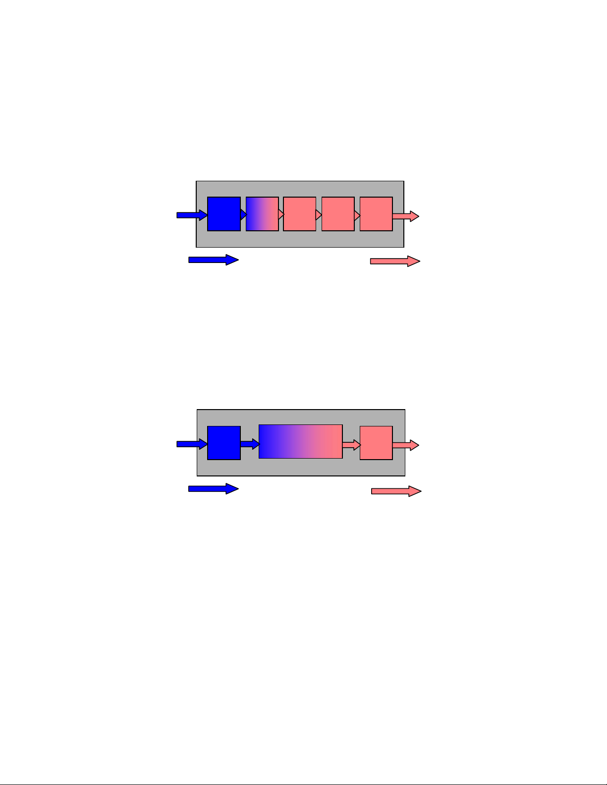
In high fidelity components, the simplest solution is usually the best
because it subjects the signal to the fewest distortion-causing processes.
Unfortunately, conventional A/V receivers are anything but simple. After Digital
Signal Processing (DSP), every signal needs to be converted back to analog, run
through a Low Pass Filter (LPF), sent through an analog volume control and then
amplified.
Input
(Digital)
DSP
Digital Signal
D/A
convert
LPF
Volume
Control
Analog
Power
Amp
Speaker
Output
Analog Signal
The conventional A/V receiver is anything but simple. The signal must
run through a gantlet of processes and stages.
The Sony S-Master Pro amplifier is dramatically different. There is no
Digital-to-Analog (D/A) converter. Instead, the amplifier accepts the digital output
of the DSP stage directly. The output of the S-Master Pro amplifier provides the
wattage that drives the speakers. In this way, the signal remains digital until the
last possible instant.
Input
(Digital)
DSP
S-Master
Power
mplifier
LPF
Speaker
Output
Digital Signal
Analog Signal
The Sony S-Master Pro amplifier dramatically simplifies receiver design.
And in high fidelity, simpler is better.
Principle of operation
The S-Master Pro amplifier accepts all digital signals directly, whether
they're multi-bit Pulse Code Modulation (PCM) or 1-bit Direct Stream Digital™
pulses, in the case of the SCD-XA9000ES SA-CD player connected via i.LINK®
interface to the STR-DA9000ES. Analog inputs undergo Analog-to-DSD
(A/DSD) conversion.
ES Receivers V3.0 Page 5
Page 6
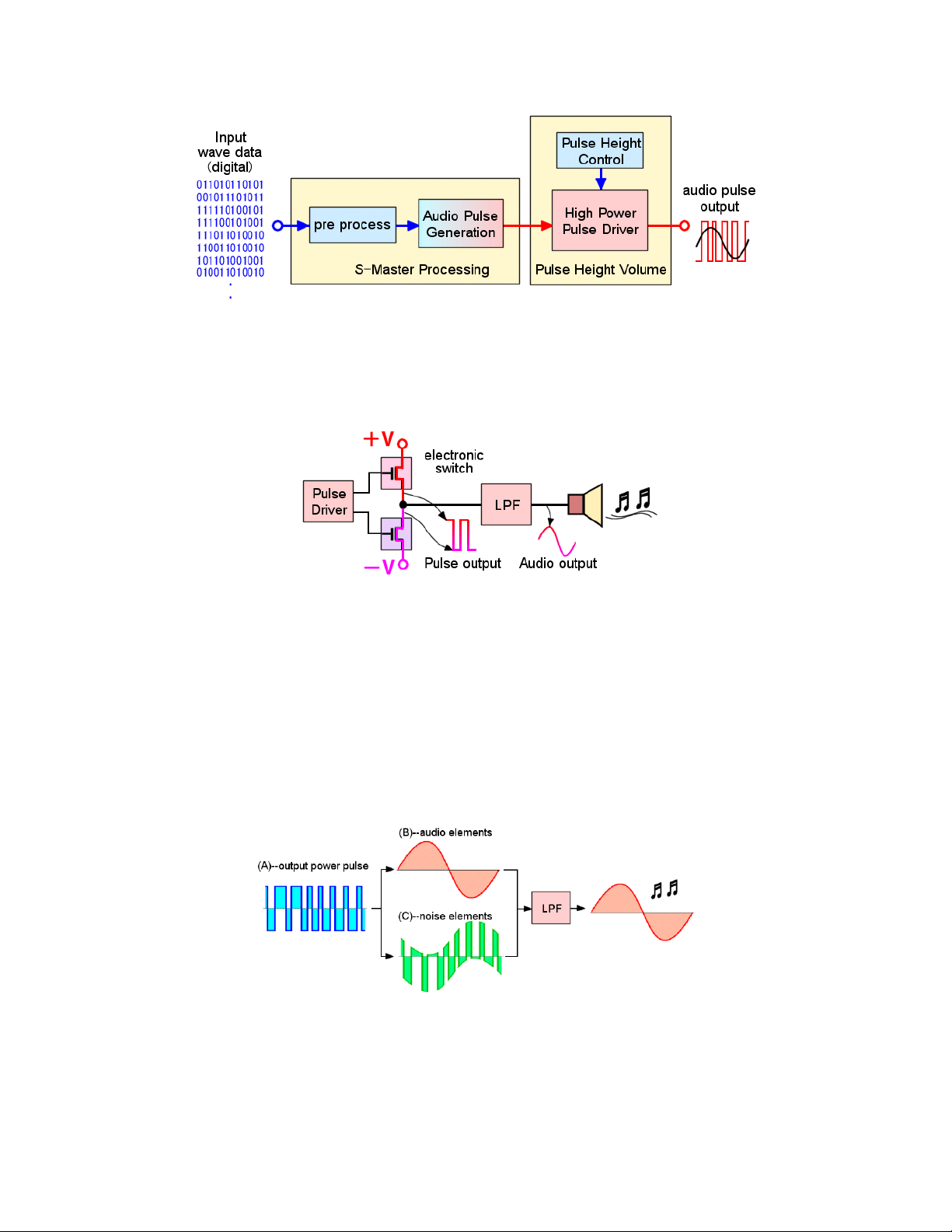
Block diagram of the S-Master Pro amplifier.
Sony generates a 1-bit pulse stream to switch a pair of FET power output
transistors on and off. The resulting output has more than enough wattage to
drive a loudspeaker.
The output transistors act like an electronic on/off switch for the power
supply voltage. The Low Pass Filter (LPF) converts the amplified
pulses to a smooth, continuous analog waveform.
The S-Master 1-bit pulse stream has much in common with the Direct
Stream Digital signal that Sony developed for Super Audio CD. If you look
carefully at the pulses, you'll see that where the audio waveform is positive, the
pulses are mostly 1. Where the audio waveform is negative, the pulses are
mostly 0. In this way, a 1-bit pulse stream can represent the audio signal. As
with a DSD signal, a Low Pass Filter (LPF) is all you need to recover the original
audio signal.
In the diagram above, (A) represents the output power pulse stream.
This combines two components, the original audio signal (B) and a
noise component (C). The audio signal (B) looks smooth and
continuous because the frequencies are low. The noise component (C)
looks abrupt and spiky because the frequencies are high. The Low
Pass Filter (LPF) effectively separates out the audio signal, for
extremely accurate music reproduction.
ES Receivers V3.0 Page 6
Page 7
Low-Pass Filtering (LPF)
(B) audio elements
(C) noise elements
Frequency
The action of the LPF. The audio signal (B) consists of low frequencies,
which pass. The red lines show the characteristic of the LPF, which
suppresses the noise elements (C) on the right. These are high
frequencies, which do not pass.
The S-Master Pro process
While Sony's S-Master Pro amplifier is simple in principle, the fidelity of
the output signal depends on getting each pulse exactly right. That is, the
leading and trailing edges of each pulse must have the right timing—and the
height of each pulse must be carefully controlled. This is comparable to the
requirements for Super Audio CD playback. So to accomplish these goals, Sony
used technologies developed for our legendary SCD-1 Super Audio CD player.
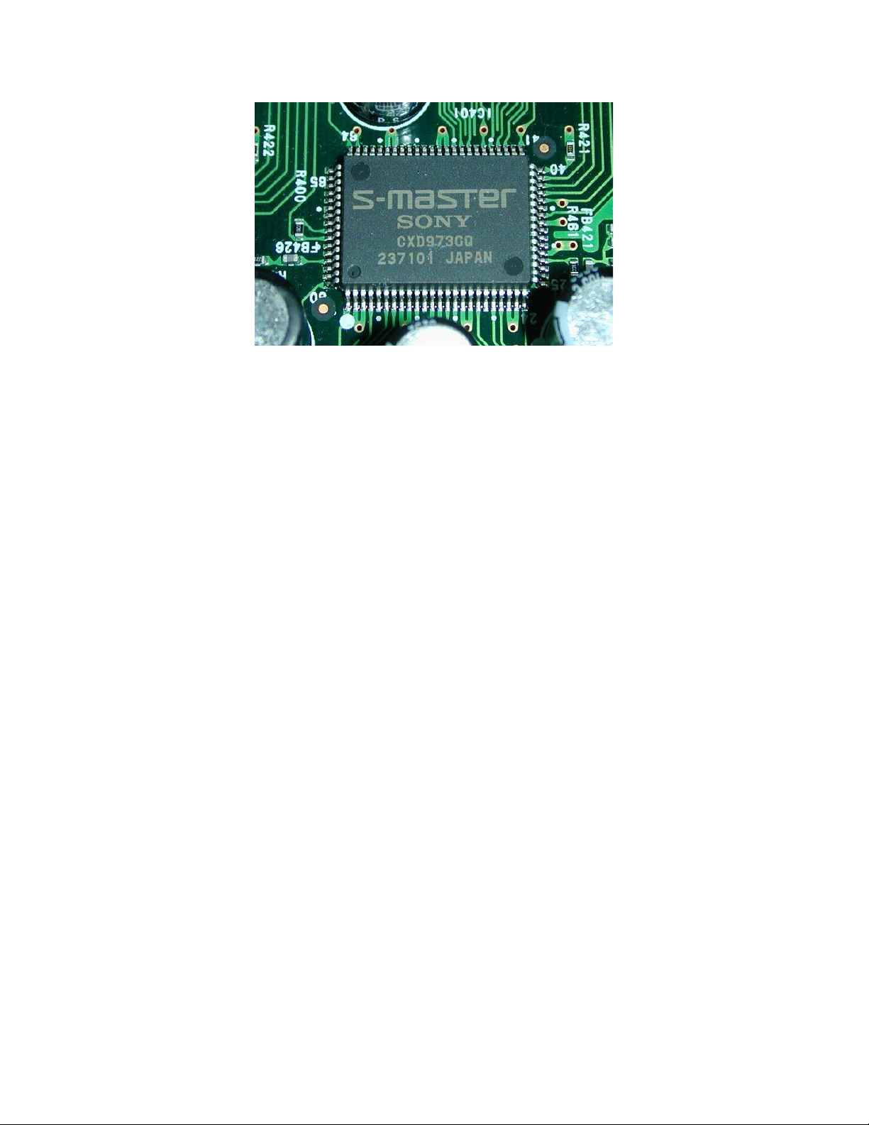
Sony's own CXD9730 Large Scale Integrated circuit (LSI) provides the
S-Master Pro processing.
The S-Master Pro process converts the incoming signal to a one-bit
Complementary Pulse Length Modulation (C-PLM) stream, after which the Pulse
Height Volume control sets the volume level. The S-Master Pro process is
performed by the Sony CXD9730, a proprietary Sony Large Scale Integrated
circuit (LSI).
ES Receivers V3.0 Page 7
Page 8
As a primary manufacturer of Large Scale Integrated circuits (LSIs),
Sony has the freedom to pursue innovative thinking like S-Master Pro
and then express this thinking in silicon. The result is the Sony
CXD9730.
The S-Master Pro system involves eight important technologies:
• Clean Data Cycle
• Synchronous Time Accuracy Controller (S-TACT)
• Complementary Pulse Length Modulation (C-PLM)
• Pulse Height Volume Control
• DC Phase Linearizer
• Discrete Output Transistors
• Toroidal Low Pass Filter
• Two-Stage Pulse Power Supply
Clean Data Cycle
While digital signals are inherently resistant to noise and distortion, they
are susceptible to time-base errors called jitter. Jitter can enter the signal during
recording, playback or transfer. Precise pulse timing is crucial to the S-Master
Pro circuit. For this reason, Sony uses powerful technology to suppress jitter.
The typical method of controlling jitter is Phase Locked Loop (PLL) clock
regeneration. While the method does a good job of controlling high-frequency
jitter, Sony also required excellent control at the low frequencies. That's why
Sony engineers developed the Clean Data Cycle, the first stage of the S-Master
process. Clean Data Cycle regenerates the digital signal with time-axis accuracy
equivalent to the original A/D converter at the recording studio.
ES Receivers V3.0 Page 8
Page 9
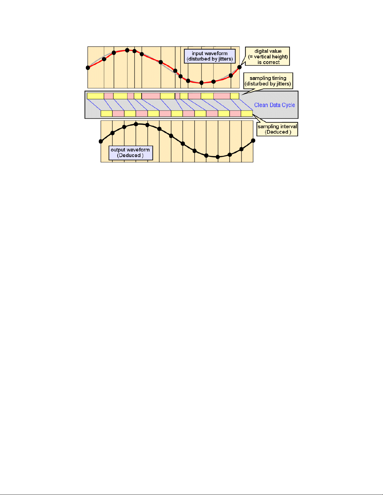
Even if the amplitude of every digital sample is 100% accurate, timeaxis jitter can distort the analog result (top). Sony's Clean Data Cycle
actually calculates the original sampling interval and applies the
calculated timing to the signal (bottom).
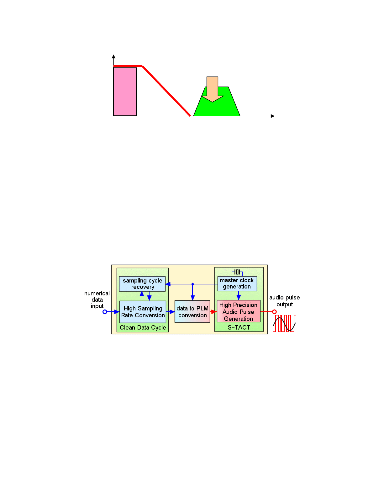
Using a supremely accurate clock, the Clean Data Cycle examines
thousands of input pulses at a time, calculates the correct sampling interval and
applies the clean interval to the output data. In this way, jitter is completely
eliminated—and the integrity of the original musical signal is restored.
Low-distortion C-PLM
After the digital signal is stabilized by the Clean Data Cycle, S-Master Pro
converts it to Complementary Pulse Length Modulation (C-PLM)—an original
Sony technology. Previous digital amplifiers have used a 1-bit technology called
Pulse Width Modulation or PWM. That is to say, those digital amplifiers varied
the width of pulses. Unfortunately, PWM tends to expose the signal to secondorder harmonic distortion. C-PLM effectively controls the distortion, maintaining
the integrity of the musical signal.
Synchronous Time Accuracy Controller (S-TACT)
Because C-PLM conversion expresses the music in a different digital
form, the signal requires another round of correction for time-base errors. For
this purpose, Sony incorporates the Synchronous Time Accuracy Controller (STACT) circuitry we developed for the SCD-1 Super Audio CD player. S-TACT
effectively clears pulse generator jitter by referencing the output directly to the
master clock. This establishes extremely accurate pulse timing for amazingly low
distortion.
ES Receivers V3.0 Page 9
Page 10
The Synchronous Time Accuracy Controller (S-TACT) maintains
accurate pulse timing at the output.
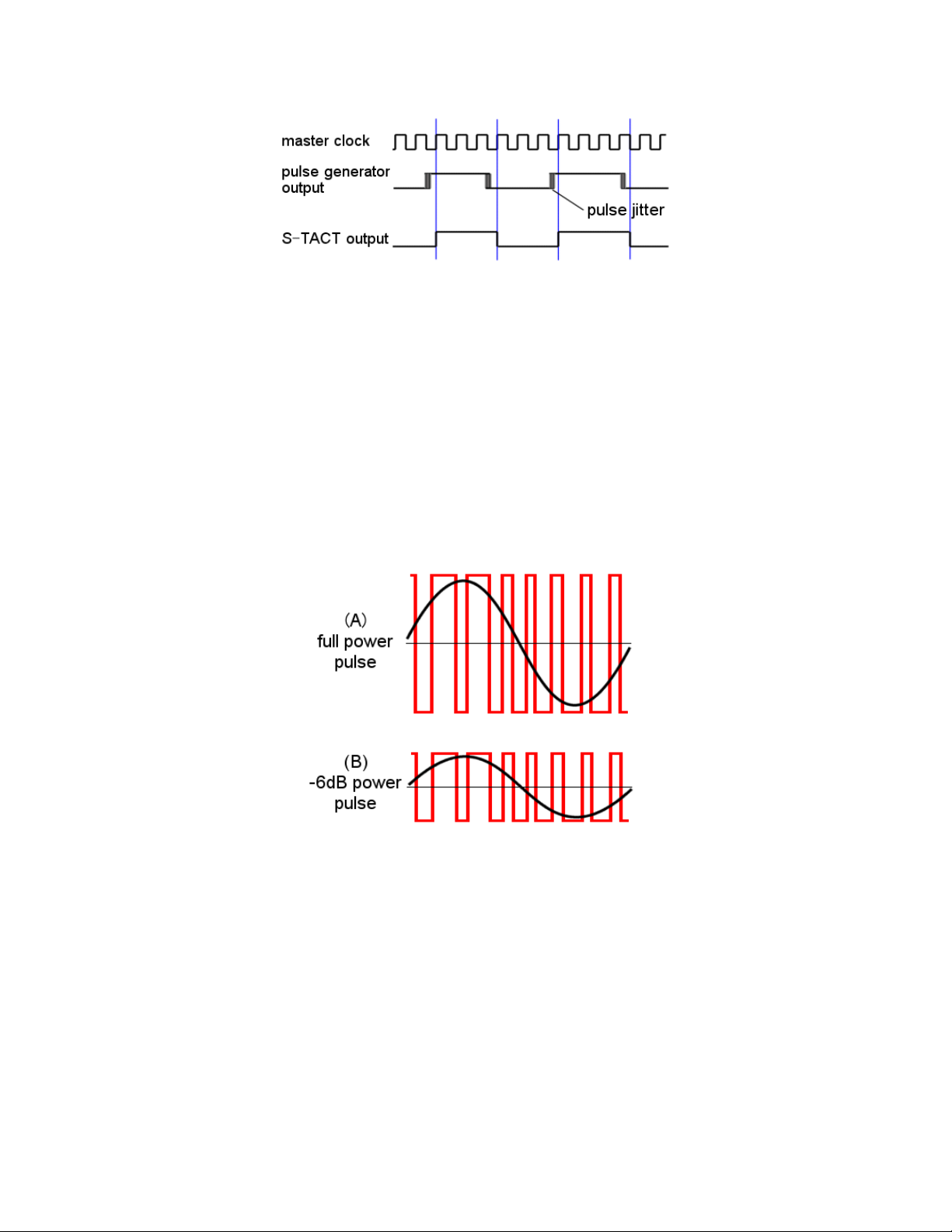
Pulse Height Volume Control
After S-TACT, the C-PLM signal passes to a Pulse Height volume
control—the place at which user volume adjustments are executed. Most digital
volume controls work by Digital Signal Processing. They adjust the sound by
multiplying the samples by a coefficient between zero and one. For example, to
achieve a volume setting 6 dB below maximum, you can multiply each sample by
0.5. This yields accurate results, but it does sacrifice some detail at the least
significant bit. Sony demanded more.
The full power pulse (A) represents the maximum setting of the volume
control. To turn the volume down 6 dB, the receiver cuts the voltage to
the power pulse generator in half (B).
In contrast, the Pulse Height Volume control adjusts the 1-bit C-PLM
stream by adjusting the regulator that supplies voltage to the power pulse
generator. Because this method does not modify or reshape the original digital
samples, there's no loss of information, no loss of detail. Sound quality is
maintained from very low volume settings like -50 dB all the way to maximum.
ES Receivers V3.0 Page 10
Page 11

DC Phase Linearizer
Digital amplifiers like the S-Master Pro design can be highly accurate—in
some respects they can even be too accurate. Phase linearity is an issue with
analog amplifiers and a contributor to analog sound. When you connect a realworld amplifier to a real-world loudspeaker, the interaction causes significant
departure from phase linearity at frequencies below 30 or 50 Hz. Sony studies
show a typical deviation from linear phase of about +90 degrees. While not
making the bass any louder or softer, this shift does have a subtle effect, creating
warmer and more accessible bass.
+90
Phase
0°
-90°
DC (0 Hz)
The low-frequency phase response of the typical analog amplifier
departs from linearity at about 30 to 50 Hz. Because many audiophiles
are accustomed to seeing frequency plotted against amplitude in
decibels, this may look like a bass boost. It is not. It's a change in
phase, which is much more subtle.
Because this phase shift is common across many brands of amplifiers at
many price points, the shift has a broad effect on loudspeaker design.
Consciously or not, loudspeaker designers take this phase shift into account
when they fine-tune the sound of their products.
This raises an interesting dilemma. Should a new digital amplifier
incorporate this phase shift or leave the sound in its original state? After
extensive listening tests, Sony decided to give users the choice of applying an
equivalent phase shift in the digital domain, using a dedicated Digital Signal
Processor, the Sony CXD9776Q. This LSI adjusts low-frequency phase with
internal accuracy equal to a 65-bit process. We call this circuit the DC Phase
Linearizer, because it "restores" low-frequency phase, emulating the signal that
the speaker would get from a top-quality analog amplifier.
30~50 Hz
Frequency
ES Receivers V3.0 Page 11
Page 12

+90
Phase
0°
-90°
DC (0 Hz)
40 Hz
Frequency
The S-Master Pro circuit reproduces this phase response, with a shift
beginning at 40 Hz.
On the STR-DA2000ES, DA3000ES and DA5000ES, the DC Phase
Linearizer provides four control positions: Off, Standard (factory preset), Mid and
High. The STR-DA9000ES offers seven control positions: Off, Low-A, StandardA (factory preset), High-A, Low-B, Standard-B and High-B. In this way, Sony
accommodates the widest range of loudspeaker designs, which may someday
include speakers based on the "flat" phase linearity of digital amplifiers like
Sony's S-Master Pro design.
Sony's DC Phase Linearizer restores the low-frequency phase response
that loudspeaker designers experience when speakers are developed.
Discrete Output Transistors
In analog amplifiers, the output transistors or ICs directly shape the analog
waveform. For this reason, analog amplifiers are extremely sensitive to the
selection, configuration, bias current and heat sinking of their output devices. By
their design, digital amplifiers are inherently less sensitive to these factors.
That's why some previous digital amplifiers have used relatively inexpensive
integrated circuit op-amps at the output. But Sony ES engineers were after the
best possible sound. So they selected discrete output transistors for the entire
ES line. The STR-DA2000ES, DA3000ES and DA5000ES use low-distortion
Field Effect Transistors (FETs), while the STR-DA9000ES uses deluxe Metal
Oxide Semiconductor FETs (MOS FETs). The result is another measure of
signal integrity.
ES Receivers V3.0 Page 12
Page 13

The discrete output FETs of the STR-DA2000ES.
Toroidal Low Pass Filter
The Low Pass Filter is a crucial stage in any digital amplifier. The filter
must have a turnover frequency high enough for high-resolution audio, yet have
a cutoff characteristic steep enough to suppress high-frequency noise elements.
In this way, the filter has a major influence on sound quality. That's why the
engineers of Sony ES selected the filter parts carefully and methodically. Instead
of choosing less expensive cylinder-type coils, the ES engineers chose exotic
toroidal coils, optimized for sound. Customers will never see these toroidal coils,
but they will hear the benefits in clean, open, non-fatiguing music reproduction.
The toroidal coils of Sony's Low Pass Filters are more expensive. But
their contribution to sound is more than worth the price.
ES Receivers V3.0 Page 13
Page 14

Two-Stage Pulse Power Supply
The power supply is always a critical component of amplifier sound
quality. And this continues to be true of digital amplifiers. That's why Sony
designed the S-Master Pro amplifiers with incredibly stable power supplies. The
STR-DA2000ES, DA3000ES and DA5000ES take advantage of Sony's twostage pulse power supply. At 200 watts per channel across seven channels
(20—20,000 Hz, 8 ohms, 0.15% THD), the STR-DA9000ES required something
even more robust, an absolutely massive Toroidal power supply, discussed later
in this paper.
Simply stated, a receiver's power supply should output stable voltage no
matter what the music is doing. Even during the most demanding musical peaks,
the power supply output should be smooth and steady. Sony's Two-Stage Pulse
Power Supply does a remarkable job in achieving exactly this result. The first
stage is a switching or "pulse" power supply of high performance. The second
stage is an analog constant voltage power supply, for an even higher degree of
stability. The cumulative effect is remarkably stable performance, even when a
rock band is playing all-out, or when a movie sound track includes car crashes
and explosions.
On the left, these fluctuations, at the input of the Pulse Power Supply,
are unacceptable for high fidelity audio reproduction. In the center, the
output of the Pulse Power Supply is substantially better, but still not up
to the standards of Sony ES. At right, after the analog constant voltage
power supply, the power is ready for true high-resolution audio
reproduction.
The pulse power supply of the STR-DA5000ES is remarkably compact
and efficient.
ES Receivers V3.0 Page 14
Page 15

S-Master Pro Benefits
V
t
t
No crossover distortion
Conventional power amplifiers use separate transistors to reproduce the
upper and lower halves of the waveform. Crossover distortion occurs when one
power transistor switches off and the other switches on as the audio waveform
"crosses over" the zero point between negative and positive. This distortion is
particularly bothersome because it remains constant as the signal gets softer.
This makes the distortion more audible during the quiet passages of music or
movies. Conventional amplifiers combat crossover distortion with the output
transistor bias current of Class A/B designs. Ironically, this bias current
generates even more heat. So in fighting one problem, designers cause another.
+V
Analog
Driver
Audio Outpu
-V
Audio Outpu
Class B analog amplifiers introduce a "kink" in the audio waveform
where the wave passes between positive and negative. Treating this
crossover distortion is a major goal of conventional amplifier design.
+V
Pulse
Driver
-
LPF
Audio Output
Audio Output
The S-Master Pro digital amplifier is immune from these issues because
the output transistors do not shape the audio waveform directly.
Because the S-Master Pro amplifier uses pulse density, switching glitches
get removed from the music by the low pass filter. The system is immune to
ES Receivers V3.0 Page 15
Page 16

crossover distortion, even when the music or movie sound track is particularly
soft.
Reduced thermal modulation distortion
Analog power amp output transistors create the shape of the audio
waveform directly. Unwanted variations in this waveform are heard directly as
distortion. Unfortunately, changes in the output signal cause momentary heating
or cooling in the transistors. These temperature changes actually alter the
performance of the transistor, which distorts the sound. This is thermal
modulation distortion.
Analog power amplifier. On the left, the waveform can cause
complex—and thoroughly unwanted—changes in the temperature and
performance of the output transistors. The impact on sound is called
thermal modulation distortion. On the right, the transistors perversely
generate the most heat at moderate output levels—the levels you're
most likely to experience most of the time. At full output, heat
generation is near zero.
In dramatic contrast, the S-Master Pro amplifier does not generate
substantial heat. So thermal effects are minimized at the source. What's more,
any small thermal effects that might persist wash out of the signal because digital
amplifier output transistors do not "shape" the output waveform in the way that
analog output transistors must. With the S-Master Pro amplifier, thermal
modulation distortion is no longer a concern.
S-Master Pro power amplifier. Here heating is low and the
temperatures stay consistent over time. On the right, you can see why
digital amplifiers can use much smaller heat sinks.
ES Receivers V3.0 Page 16
Page 17

The STR-DA2000ES packs 120 watts per channel (20—20,000 Hz, 8
ohms, 0.8% THD). Yet the output transistors generate so little heat that
they can be mounted directly onto the S-Master Pro circuit board and
cooled by heat sinks less than one inch high!
Simple and straight design
Heat is always bad for electronics. That's why the heat thrown off by
conventional power output transistors is a crucial constraint in amplifier and
receiver design. And that's why so many high-power amplifiers require massive
internal heat sinks, cooling fans, and chassis layouts that isolate the output
transistors at the back or sides. In contrast, the tremendous thermal efficiency of
the S-Master Pro amplifier changes everything.
Instead of isolating the power output transistors, Sony can place them in
the middle of a circuit board. Instead of massive aluminum heat sinks, the SMaster Pro heat sinks can be quite compact, especially on the STR-DA2000ES
and DA3000ES. And instead of a complex, circuitous signal flow, driven by the
need to hold the output transistors away at the periphery, the S-Master Pro signal
flow can be refreshingly simple and straight.
ES Receivers V3.0 Page 17
Page 18

The internal layout of the STR-DA4ES analog amplifier is driven by the
issue of heat dissipation. The entire design is dominated by the output
transistor heat sink fins.
In dramatic contrast, the power amplifier of the STR-DA2000ES is
amazingly compact. The S-Master LSIs (1) convert the signal to a
Pulse Length Modulation 1-bit stream. Thanks to low heat generation,
the power output transistor heat sinks (2) can be quite small. Finally,
the Low-Pass Filters (3) convert the power pulses to audio for the
speaker terminals at the top of the picture.
ES Receivers V3.0 Page 18
Page 19

In the STR-DA4ES (top), the signal flows from the center, to the sides
and back to the center again for point-to-point wiring to the speaker
output terminals. It's anything but straightforward. On the STRDA2000ES (bottom), the signal flows in one direction only.
Superb open-loop performance
Conventional amplifiers typically generate substantial distortion in "openloop" mode. That's why analog amps use Negative Feedback (NFB). NFB
constantly compares the output with the input, identifying open-loop distortion
and applying an equal-but-opposite correction signal at the input. NFB is a
powerful tool for limiting distortion, and NFB explains the low distortion
specifications common today. However, NFB exposes the signal to Transient
Intermodulation Distortion and other dynamic problems.
In contrast, the Sony S-Master Pro amplifier achieves excellent fidelity
without any negative feedback at all! Distortion remains low without any sacrifice
in transient and dynamic characteristics. Music comes alive. And movie sound
effects like car crashes and gunshots retain all their original impact.
Musicality and transparency
Armed with S-Master Pro amplifier technology, the latest ES Series
receivers stand apart. They deliver high power output (up to 200 watts per
ES Receivers V3.0 Page 19
Page 20

channel x7, 8 ohms, 20 to 20,000 Hz, 0.15%), and exceptional sound quality.
Music is rendered in very high resolution, against a background of silky silence.
Dynamics are powerful but not forced. Bass is vigorous but not boomy. These
receivers are perfect for integration with the most difficult and power-hungry
speakers. Use good speaker cables, a suitable disc player and a Super Audio
Compact Disc that you know well. Then sit back and listen carefully. The results
speak for themselves.
ES Receivers V3.0 Page 20
Page 21

Other New Features
A
r
i.LINK® Digital Audio Interface (STR-DA9000ES)
From the initial launch of Super Audio Compact Disc, the 1-bit Direct
Stream Digital™ pulse train was always converted to analog prior to output from
the player. While SA-CD players have included coaxial and optical digital
outputs, these outputs handled CD signals exclusively. The SCD-XA9000ES is
Sony's first SA-CD player to provide an i.LINK digital output for the 1-bit DSD
signal. The STR-DA9000ES is Sony's first receiver to incorporate an i.LINK
digital input. The i.LINK interface maintains the signal in the digital domain and
can simplify the signal path considerably. The i.LINK interface also enables a
single digital cable to take the place of six analog cables.
SA-CD Player
SA-CD
D/A
convert
SCD-XA9000ES
SA-CD
Digital Signal
Typical SA-CD reproduction involves numerous D/A and A/D
conversions. Connected to a compatible SA-CD player, the STRDA9000ES maintains the signal in digital form.
A/D
convert
DSP
mplifier
DSP
D/A
convert
STR-DA9000ES
S-Master Power Amplifie
LPF
Volume
Analog Signal
Analog
Power
Amp
LPF
Speakers
Speakers
The i.LINK digital audio interface uses Digital Transmission Content
Protection (DTCP), a robust system that protects the music from piracy. The
application of the i.LINK (IEEE 1394) interface to digital audio is clearly different
from—and not compatible with—previous i.LINK interface applications for DV
camcorders, PC peripherals and professional digital video systems. You can
only connect the STR-DA9000ES i.LINK interface to a compatible digital audio
output, such as that on the SCD-XA9000ES SA-CD player.
ES Receivers V3.0 Page 21
Page 22

The design of the interface is exceptional because communicating six
streams of 2.8224 MHz digital samples raises exceptional challenges.
Conveying 1-bit signals at such high data rates and synchronizing the signals
with the receiver's master clock would normally expose the signal to the timebase errors called jitter. These errors translate directly into time-based distortion
of the audio waveform.
Sony overcame this challenge with the High quality digital Audio
Transmission System (HATS). HATS uses "command-based rate control of
isochronous data flow" to solve the problem. The system incorporates three
principal elements.
1. Variable-speed transmission from the player.
2. Buffer memory in the receiver.
3. Command signals from the receiver to the player, controlling transmission
speed.
SCD-XA9000ES
STR-DA9000ES
With Sony HATS, audio data flows from the player to the receiver's
buffer memory, according to rate control commands from the receiver.
Reproduction in the receiver achieves the full time base accuracy of the
receiver's quartz crystal master clock.
The receiver continually monitors the amount of audio data in its buffer
memory. When the buffer memory reaches its lower limit, the receiver
commands the player to increase data transmission speed. When the buffer
memory reaches its upper limit, the receiver commands the player to decrease
transmission speed. And when the buffer memory is between the upper and
lower limits, the receiver commands the player to transmit at normal speed.
In this way, HATS makes it unnecessary to synchronize a jitter-prone
signal with the receiver master clock. Instead, the buffer memory outputs a jitterfree signal at the full quartz-crystal accuracy of the receiver's master clock. You
get all the benefits of digital transmission, without the exposing the signal to the
potential for jitter-induced distortion.
ES Receivers V3.0 Page 22
Page 23

Component Video Upconversion
(STR-DA3000ES and higher)
As the nerve center of modern home entertainment, the A/V receiver
needs to handle the full range of audio/video sources, including everything from
HDTV receivers, digital satellite receivers and DVD recorders to VHS decks and
videogames. Along with the range of sources comes a range of potential video
input types: from the relatively low-grade composite video to S-Video, component
video and HD component video. Ideally, all of these signals should be conveyed
to the television with the highest possible quality. And for the sake of
convenience alone, all of these signals should be conveyed to the same input of
the television. That's why the STR-DA3000ES, DA5000ES and DA9000ES
upconvert Composite Video to S-Video as well as upconverting S-Video to
Component Video. Through these upconversions, Sony provides a high-quality
connection to the television, while simultaneously reducing the need to switch
input sources at the television.
These upconversions are made possible by two Sony large-scale
integrated circuits (LSIs), which draw on years of Sony IC experience. Sony's
CXD2064 digital LSI performs Composite to S-Video upconversion, while the
analog CXA2199 upconverts S-Video to Component Video. Some previous
upconversion circuits could not control the Hue, Contrast and Brightness of
converted signals. But thanks to the CXA2199, Sony receivers give you these
capabilities.
On the left, Sony's CXD2064 upconverts Composite Video to S-Video.
On the right Sony's CXA2199, upconverts S-Video to Component Video.
Together, the circuits ensure high-quality connections to your
television—and simplify system operation.
DVI Interface (STR-DA9000ES)
The STR-DA9000ES can accommodate the latest digital video sources
with two digital inputs and one output. The Digital Visual Interface (DVI) enables
spectacular, uncompressed digital-to-digital transport of a High Definition video
ES Receivers V3.0 Page 23
Page 24

signal. The connection is also secured by HDCP technology to protect the signal
from piracy.
Lip Sync (STR-DA5000ES and DA9000ES)
Today's advanced televisions and video projectors often incorporate
sophisticated video signal processing to optimize the image quality. Often, these
circuits require buffer memories that result in a slight delay of the video signal.
Unfortunately, this can result in a mismatch, where the television picture lags
behind the sound from the speakers by some fraction of a second. As you can
imagine, the effect can be unnatural and annoying.
That's why Sony provided the STR-DA5000ES and DA9000ES with Lip
Sync. This circuit enables you to correct time misalignments between the audio
and video signals by up to 200 milliseconds, in 10 millisecond increments. This
brings your television and your home theater speakers back into alignment. This
Lip Sync is performed uniformly on stereo, 7.1-channel and even digital audio
inputs.
The STR-DA5000ES performs Lip Sync with another Sony Large Scale
Integrated circuit, the CXD9722.
9.1-Channel Operation (STR-DA9000ES)
The STR-DA9000ES offers an ingenious arrangement of the A and B
speaker terminals. The speaker selector switch includes positions for A, B and A
+ B. In the A + B position, the receiver can drive two Surround Left and two
Surround Right speakers, in addition to a Surround Back pair. Of course, this 9.1
configuration is closer to the array of surround speakers used in a commercial
movie theater. It's also exactly the same as the 9.1-channel configuration of
Hollywood dubbing theaters!
ES Receivers V3.0 Page 24
Page 25

Toroidal Power Supply (STR-DA9000ES)
Like the STR-DA2000ES, DA3000ES and DA5000ES, the top-of-the-line
DA9000ES operates the S-Master Pro amplifier from a two-stage power supply.
And like these other receivers, in the DA9000ES, the second stage is an analog,
constant voltage supply. But where the other receivers use a Pulse Power
Supply, the DA9000ES uses an analog supply with a giant toroidal core power
transformer. Sony made this choice for strictly practical reasons: we could not
build a pulse power supply with the current capability for 200 watts per channel,
for 7 simultaneous channels into 8 ohms (20—20,000 Hz, 0.15% THD).
For this reason, the first stage of STR-DA9000ES power supply wields an
extremely massive toroidal-core power transformer. In fact, the unusual height of
the DA9000ES chassis is determined in part by the size of the power
transformer. Thanks to this transformer, the current delivery of the DA9000ES is
an incredible 12 amps per channel. This is more than enough current to drive
"difficult," low-impedance loudspeakers, including models rated at 4 ohms with
impedance dips down to 2 ohms!
Power transformer cores and windings can vibrate and degrade the
sound, radiating 60 Hz hum into nearby audio circuits. That's why Sony chose
the toroidal core design, which enables the transformer windings to be wrapped
without the voids or gaps that permit vibration. This results in far less radiation,
far less radiated hum.
The extraordinary size and weight of the STR-DA9000ES receiver is
explained in part by the size and weight of this toroidal-core power
transformer.
ES Receivers V3.0 Page 25
Page 26

MOS FET output transistors (STR-DA9000ES)
To achieve 200 watts x7 (20—20,000 Hz, 8 ohms, 0.15% THD), the STRDA9000ES incorporates some unique power amplifier technology. For example,
the power amplifier uses Metal Oxide Semiconductor Field Effect Transistors
(MOS FETs), highly prized for their linearity. Four MOS FETs per channel are
configured in modules that are direct-mounted to heat sinks in a "circuit-onchassis" configuration.
The STR-DA9000ES power amp circuit board features seven heat sinks
for the seven output channels.
The output stage is attached to the underside of each heat sink in a
"circuit-on-chassis" configuration. The black capsules in this picture
protect and insulate the four MOS FETs.
ES Receivers V3.0 Page 26
Page 27

Conventional transistors are packaged in plastic with prefabricated
leads (left). To achieve the shortest possible signal path, Sony uses
bare MOS FETs and employs molecular bonding to connect each lead
to the circuit board. The bare transistors and their connections are then
encapsulated for protection.
Even the method of attaching the MOS FETs to the circuit board is
remarkable. Instead of using conventional, packaged transistors, Sony uses
"bare" transistors and molecular bonding. While expensive and time consuming,
this approach makes for the shortest possible signal paths. Sony then protects
the assembly with encapsulation in a protective compound.
Motherboard Topology (STR-DA9000ES)
To shorten the signal paths and optimize the circuit topology, the STRDA9000ES uses an internal configuration that's rare in home audio, but common
in computers. The receiver features a large motherboard that forms a "floor" and
provides interconnections to daughterboards that process the signal. Input
signals go directly into an input board, of which one edge is mounted to the back
panel and one edge is mounted to the motherboard. Then the input board signal
flows through the motherboard to the S-Master Pro power amplifier.
Power supply voltage travels a similar route, from the opposite side. In
this way, Sony keeps signal leads to a minimum, protecting the music from the
radiation of spurious hum and noise.
ES Receivers V3.0 Page 27
Page 28

For efficient space utilization and minimum point-to-point wiring, the
STR-DA9000ES uses a motherboard/daughterboard circuit topology.
Silver Cascade Design (STR-DA3000ES and up)
In addition to their remarkable technology, these receivers inaugurate a
new faceplate design exclusive to the Sony ES Series. The "cascade" design
sets the primary front panel controls at an angle, so that you can use them
without uncomfortable bending and stooping to identify each control. The silver
colored faceplate is made of brushed aluminum and fits in beautifully with
conventional audio components. But the design really comes into its own when
the receivers are combined with other silver cascade components, such as the
SCD-XA9000ES Super Audio CD player or the DVP-NC555ES DVD/CD/SA-CD
5-disc changer.
The DVP-NC555ES 5-disc DVD/CD/SA-CD changer shows how the
Silver Cascade design extends to source components.
ES Receivers V3.0 Page 28
Page 29

Here is a summary of the cosmetics in the 2003 ES Series.
SILVER CASCADE FRONT PANELS
• STR-DA9000ES A/V receiver
• STR-DA5000ES A/V receiver
• STR-DA3000ES A/V receiver
• SCD-XA9000ES SA-CD player
• DVP-NC555ES DVD changer
MATCHING SILVER FRONT PANELS
• STR-DA2000ES A/V receiver
• STR-DA1000ES A/V receiver
• DVP-NS999ES DVD player (Silver or Black)
• DVP-CX777ES DVD changer
• RCD-W2000ES CD recorder
• AVD-C700ES DVD receiver
• AVD-S500ES DVD receiver
ES Receivers V3.0 Page 29
Page 30

Continuing Features
Of course, the latest ES Series A/V receivers reflect the lessons learned in
two decades of ES refinements and improvements. These models have the full
complement of ES decoding, Digital Signal Processing, control and integration
technologies.
• Seven channels of amplification (all models). This configuration can drive
separate Surround Back Left and Surround Back Right speakers, ideal for
both 5.1- and 6.1-channel sources.
• Auto channel grouping (all models). The feature adapts the reproduction
to match a 7-speaker configuration. In reproducing 5.1-channel sources, the
four Surround speakers are driven in two groups (SL and SR). In reproducing
6.1-channel sources, the Surround speakers are driven in three groups (SL,
SB and SR).
• Full complement of digital and analog surround decoding (all models).
Sony provides decoding for all of the following sources:
o Dolby Digital® surround sound
o Dolby Digital EX 6.1-channel sound
o Dolby® Pro Logic® surround sound
o Dolby Pro Logic II-movie and Pro Logic II-music
o dts® 5.1-channel surround sound
o dts 96/24
o dts ES discrete 6.1 and dts ES matrix 6.1
o dts Neo6:cinema and dts Neo6:music
• 32-bit surround sound decoding (all models). Using a proprietary Sony
Large Scale Integrated circuit (LSI).
• 6.0-channel Digital Cinema Sound concert hall modes (all models). For
the Amsterdam Concertgebouw and the Vienna Musikvereinsaal.
• 7.1-channel Cinema Studio EX modes (all models). Recreate the
acoustics of the Hollywood dubbing stages where directors go to audition and
approve their final sound mixes.
• 7.1-channel Virtual Multi Dimension (all models). Recreates the effect of a
full array of Surround speakers.
• 12V triggers (STR-DA2000ES and higher). ES receivers are destined to be
used in custom installations where curtains, screens and lighting "scenes"
may require 12-volt triggers.
• Infrared repeater ports (STR-DA2000ES and higher). To accommodate
installations where the stack of electronics is hidden away, ES receivers offer
one infrared repeater input and two outputs. This means you can place an
inconspicuous IR "eye" in the home theater room and still control your
components.
ES Receivers V3.0 Page 30
Page 31

• RS-232C interface (STR-DA2000ES and higher). To communicate with
third-party room automation systems, these receivers include RS-232C ports.
The ports also enable future firmware upgrades to the STR-DA5000ES and
DA9000ES.
• Front optical digital audio input (all models). As part of the Video 3 input
of the front panel, these receivers also accept optical digital audio, in addition
to Left/Right analog audio.
• Assignable digital input (all models). An optical or coaxial digital input can
be flexibly assigned to any video input, providing greater versatility when
connecting a second DVD player, an HDTV tuner or other digital video source
component.
• A/B speaker terminals (all models). Real estate on the back panel of
modern A/V receivers is severely limited. At the request of ES dealers, Sony
found a way to add a set of B speaker terminals.
Conclusion
Beginning with the PCM-701ES digital processor in 1982, the engineers of
Sony ES have been extending the capabilities of digital audio. Breakthroughs
like the S-Master Pro amplifiers take audio reproduction to the next stage in
sophistication, simplicity and sound quality. These ES receivers represent
another milestone in the digital technology. To appreciate the difference, just
turn them on and listen.
ES Receivers V3.0 Page 31
Page 32

Features and specifications
Feature STR-
DA9000ES
Power output, 8 ohms, 20 to
20,000 Hz at rated THD
THD at rated power output 0.15% 0.8% 0.8% 0.8% 0.09%
S-Master Pro Amplifier Yes Yes Yes Yes DC Phase Linearizer 6 positions +
Dolby Digital® EX decoding Yes Yes Yes Yes Yes
dts® ES decoding Yes Yes Yes Yes Yes
dts 96/24 decoding Yes Yes Yes Yes Yes
Dolby® Pro Logic® II decoding Yes Yes Yes Yes Yes
dts Neo:6 decoding Yes Yes Yes Yes Yes
Digital Cinema Sound circuit 7.1-channel 7.1-channel 7.1-channel 7.1-channel 7.1-channel
32-bit Decoder Yes Yes Yes Yes Yes
32-bit DSP Yes (Two) Yes (Two) Yes (Two) Yes Yes
Lip Sync Yes Yes - - OP Processing - - - - Yes
Auto channel grouping Yes Yes Yes Yes Yes
A/B speaker terminals Yes Yes Yes Yes Yes
Multi-channel inputs 7.1 (x2) 7.1, 5.1 7.1, 5.1 7.1, 5.1 5.1
DVI inputs/outputs 2/1 -/- -/- -/- -/HD Component video
inputs/output
S-Video to Component
upconverter
Composite to S-Video
upconverter
S-Video inputs/outputs 7/3 4/2 4/2 3/1 3/1
Composite video
inputs/outputs
i.LINK® digital audio input Yes - - - Optical inputs/outputs 6/2 5/1 5/1 3/1 3/1
Coaxial inputs 5 2 2 1 1
Multi-channel preamp output Yes, 7.1
Front A/V input with optical
digital audio
Infrared repeater input/outputs 1/2 1/2 1/2 1/1 -/RS-232C control/upgrade Yes/Yes Yes/Yes Yes/- Yes/- -/12-volt trigger outputs 5 3 2 1 On screen display Yes Yes Yes Yes Yes
Multi-Zone/Room Capability 3/3 3/3 2/2 2/2 -/2nd Room output A/V out A/V out A/V out Audio out 3rd Room output Audio Audio - - Remote Features
Preprogrammed LCD Yes Yes Yes Yes Yes
Learning & Macro Yes Yes Yes Yes Yes
2-way Yes Yes - - Touch-screen Yes - - - Second-room remote Yes Yes Yes - -
200 watts x7 170 watts x7 150 watts x7 120 watts x7 100 watts x7
Off
3/1 2/1 2/1 2/1 2/1
Yes Yes Yes - -
Yes Yes Yes Yes Yes
7/3 4/2 4/2 4/1 4/1
channels
Yes Yes Yes Yes Yes
STRDA5000ES
3 positions +
Off
Yes, 7.1
channels
STRDA3000ES
3 positions +
Off
Yes, 7.1
channels
STRDA2000ES
3 positions +
Off
L, R,
Subwoofer
STRDA1000ES
-
Subwoofer
ES Receivers V3.0 Page 32
Page 33

Sony Electronics Inc.
1 Sony Drive, Park Ridge, NJ 07656
www.sel.sony.com
© 2003 Sony Electronics Inc. All rights reserved. Reproduction in whole or in part without written
permission is prohibited. Features and specifciations are subject to change without notice. Non-metric
weights and measures are approximate Sony, Digital Cinema Sound, Direct Stream Digital and i.LINK are
trademarks of Sony. Dolby, Dolby Digital and Pro Logic are trademarks of Dolby Laboratories Licensing
Corporation. dts is a trademark of Digital Theater Systems Corporation. All other trademarks are property
of their respective owners.
ES Receivers V3.0 Page 33
 Loading...