

Page 1

FM Stereo
FM-AM Receiver
3-758-526-21(4)
Operating Instructions
STR-D915
SÌR-D715
e 1994 by Sony Corporation
Page 2
Warning
WARNING
To prevent fire or shock hazard, do not
expose the unit to rain or moisture.
CAUTION
RISK OF ELECTRIC SHOCK
i
CAUTION: TO REDUCE THE RISK OF ELECTRIC SHOCK.
00 NOT REMOVE COVER (OR BACK).
NO USER-SERVICEABLE PARTS INSIDE.
REFER SERVICING TO QUALIFIED SERVICE PERSONNEL
This symbol is intended to alert the user to
the presence of uninsulated "dangerous
voltage" within the product's enclosure that
may be of sufficient magnitude to constitute
a risk of electric shock to persons.
This symbol is intended to alert the user to
the presence of important operating and
maintenance (servicing) instructions in the
literature accompanying the appliance.
DO NOT OPEN
] ZlA
INFORMATION
This equipment has been tested and found to comply with
the limits for a Class B digital device, pursuant to Part 15 of
the FCC Rules.
These limits are designed to provide reasonable protection
against harmful interference in a residential installation.
This equipment generates, uses, and can radiate radio
frequency energy and, if not installed and used in
accordance with the instructions, may cause harmful
interference to radio communications. However, there is no
guarantee that interference will not occur in a particular
installation. If this equipment does cause harmful
interference to radio or television reception, which can be
determined by turning the equipment off and on, the user is
encouraged to try to correct the interference by one or more
of the following measures;
— Reorient or relocate the receiving antenna.
— Increase the separation between the equipment and
receiver.
— Connect the equipment into an outlet on a circuit
different from that to which the receiver is connected.
— Consult the dealer or an experienced radio/TV
technician for help.
CAUTION
You are cautioned that any changes or modifications not
expressly approved in this manual could void your
authority to operate this equipment.
WARNING
To prevent shock hazard, do not insert the plug cut off from
the mains lead into a socket outlet. This plug cannot be
used and should be discarded.
Note to CATV system installer
This reminder is provided to call the CATV system
installer's attention to Article 820-40 of the NEC that
provides guidelines for proper grounding and, in
particular, specifies that the cable ground shall be
connected to the grounding system of the building, as
close to the point of cable ent^ as practical.
Owner's Record
The model number is located on the rear exterior and serial
number is on the rear. Record the serial number in the space
provided below. Refer to these numbers whenever you call
upon your Sony dealer regarding this product.
Model No. STR-D915 Serial No.
Model No. STR-D715 Serial No.
If the plug supplied with this appliance has detachable fuse
cover, be sure to attach the fuse cover after you change the
fuse. Never use the plug without the fuse cover.
If you should lose the fuse cover, please contact your
nearest Sony service station.
For the customers In Canada
r— CAUTION:--------------------------------------------------
TO PREVENT ELECTRIC SHOCK, DO NOT USE THIS
POLARIZED AC PLUG WITH AN EXTENSION
CORD, RECEPTACLE OR OTHER OUTLET UNLESS
THE BLADES CAN BE FULLY INSERTED TO
PREVENT BLADE EXPOSURE.
This apparatus complies with the Class B limits for radio
noise emissions set out in Radio Interference Regulations.
Page 3

Table of Contents
Introduction
Overview.............................................j
Precautions
Chapter 1 Getting Started
Unpacking...........................................;
Checking the Supplied Accessories
Inserting Batteries into the Remote Commander.......... 5
Hooking Up the System......................................................6
Notes on Connections
Connecting Audio Equipment
Coimecting Video Equipment.......................................6
Connecting an FM Antenna
Connecting the Antenna Ground .................................
Connecting an AM Antenna..........................................7
Connecting Speaker Systems
Connecting to the AC Power Outlet
Chapter 2 Basic Operations
Listening to/Watching a Program Source...........................9
Selecting a Program Source
Selecting the Speaker System
Adjusting the Audio
Labeling the Program Source.......................................10
To Turn Off the Power at the Desired Time
Receiving Broadcasts
Tuning in a Station Directly (Direct Tuning)
Automatic Tuning
Presetting Stations.......................................................12
Tuning in a Preset Station (Preset Tuning)
Labeling the Preset Stations (Statioq Index)
Selecting a Station among the Preset Stations in the
Receiving FM Simulcast TV Programs
Remote Controls
Using the Remote...........................;
Changing the Settings of the FUNCTION Buttons
.......................................................................
...................................................
....................................................
(The Sleep Timer Function)......................................10
.......................................................
......................................................
Index (Index Tuning)
...............................................................
.................................................
..............................
4
..............................
..............................
......................................
..........................................
........................................
.............................
..........................................9
.......................................9
9
11
.............
................
................
......................
.............................
11
12
13
15
16
......
4
5
5
6
6
7
7
8
8
14
15
16
17
Obtaining the Surround Soimd
Placement of Speakers and Selecting the
CENTER MODE for Dolby Surround Sound
Adjusting the Speaker Volume...................................21
Adjusting the E)elay Time of the Rear Speakers
Sound Field Settings.........................................................23
Available Type of Effects
Adjusting the Sound Field Programs
Calling up the Sound Field Setting
Chapter 4 Other Information
Troubleshooting Guide
Specifications....................................................................28
Identif)dng the Parts and Controls....................................31
Front Panel..................................................................31
Remote Commander
(Except for the STR-D915 for Canadian Model)
Quick Reference
...............................................................
.........................................
..........
........
...........................................
..........................
.............................
....................................................
.....
20
20
22
23
24
25
26
32
33
Chapter 3 Advanced Operations
Recording an Audio Source
Recording on a Tape
Editing a Video Source..................................................... 18
Recording on a Video Tape
Adding New Sound on a Video Tape during Video
Editing.......................................................................19
...............................................
....................................................
........................................
18
18
18
Page 4

Overview
Precautions
The STR-D915/D715 is an FM Stereo/FM-AM receiver and
audio/video control center.
You can enjoy various audio/video program sources with
this unit.
TV/video programs
• You can enjoy TV or CATV programs with FM simulcast.
• Sounds from various audio program sources can be added
on video tapes during editing.
Tuner
• Precise tuning is ensured by a quartz locked digital
synthesizer.
• Station Index system allows you to tune into a station
quickly.
DOLBY* PRO LOGIC
In the DOLBY SUR or THEATER mode, the center mode can
be selected. The Dolby Pro Logic Surround Decoder has the
same functions for playback as movie theaters and gives a
theater-like experience in your listening room, naturally
reproducing the audio sound field.
• Manufactured under license from Dolby Laboratories Licensing
Corporation. Additionally licensed under one or more of the
following patents: U.S. number 3,959,590; Canadian numbers
1,004,603 and 1,037,877. "DOLBY", "Pro Logic", and the double-D
symbol are tradeituirks of Dolby Laboratories Licensing
Corporation.
Sound field (combination of digital delayed surround and tone controls)
• 6 recommended sound field programs (DOLBY SUR,
THEATER, LIVE, HALL, DANCE, ACOUSTIC) are preset
in the factory for easy use. You can also store up to 6
settings you created in the memory.
• Combined use of the sound held programs and the preset
stations or program source allows you to enjoy broadcast
or program source listening immediately with the
memorized 6 settings of sound field (DOLBY SUR,
THEATER, LIVE, HALL, DANCE, ACOUSTIC).
Remote commander
The supplied remote commander allows you to remotely
control this receiver and the equipments connected to the
receiver.
For the instruction of the remote commander, see pages 16
and 17.
As for the instruction of the remote commander for STRD915 Canadian model, see the operating instructions of the
separate volume.
On safety
• For the U.S.A. and Canadian models, operate the unit
only on 120 V AC, 60 Hz.
• For Australian model, operate the unit only on 240 V AC,
50 Hz.
• Should any solid object or liquid fall into the cabinet,
unplug the unit and have it checked by qualified
personnel before operating it any further.
• Unplug the unit from the wall outlet if it is not to be used
for an extended period of time. To disconnect the cord,
pull it out by grasping the plug. Never pull the cord
itself.
• One blade of the plug is wider than the other for the
purpose of safety and will fit into the power outlet only
one way. If you are unable to insert the plug fully into the
outlet, contact your dealer, (except for Australian model)
• The unit is not disconnected from the AC power source
(mains) as long as it is connected to the wall outlet, even if
the unit itself has been turned off.
On operation
Before making program source connections, be sure to
turn the power switch off and unplug the unit.
To prevent internal heat buildup in the unit,
place the unit in a location with adequate air circulation.
Do not install the unit:
• near heat sources such as radiators or air ducts.
• in a place subject to direct sunlight, excessive dust,
mechanical vibration or shock.
Do not place anything on top of the cabinet.
The top ventilation holes must be unobstructed for the
proper operation of the unit and to prolong the life of its
components.
On cleaning the cabinet
Clean the cabinet, panel and controls with a soft cloth
lightly moistened with mild detergent solution. Do not use
any type of abrasive pad, scouring powder, or solvent such
as alcohol or benzine.
For the customers in the U.S.A.
For detailed safety precautions, see the "IMPORTANT
SAFEGUARDS" leaflet.
If you have any question or problem concerning your unit,
please consult your nearest Sony dealer.
Page 5
Unpacking
Do not throw away the carton and packing material!
It will be an ideal container when transporting the system for
repair work, etc.
Checking the Supplied Accessories
After unpacking, check that the following accessories are
present.
• FM wire antenna
.......................................................
(1)
• AM loop antenna.........................................................(1)
• Remote commander
• Sony batteries SUM-3 (NS)
....................................................
...........
.j.
...........................
I
(1)
(2)
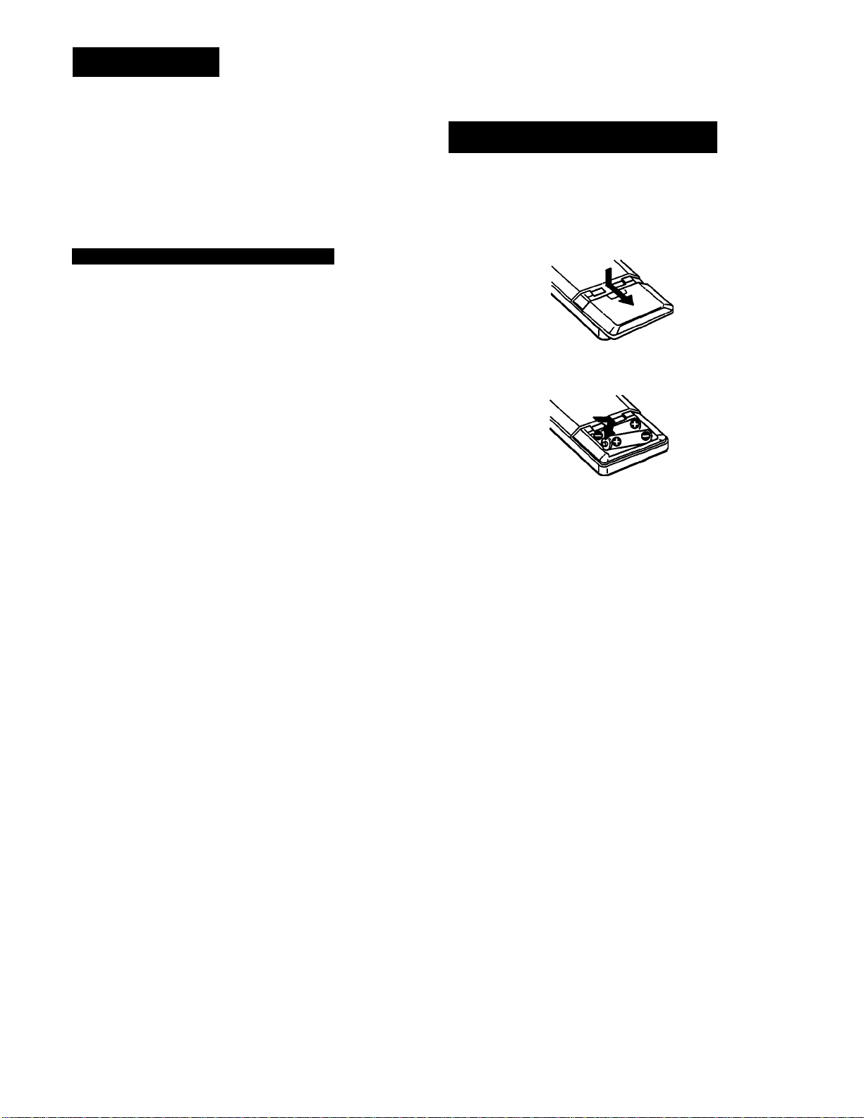
Inserting Batteries into the Remote
Commander
Before operating the remote commander, install the batteries
as shown below.
Open the cover.
Insert two size-AA (R6) batteries with
correct poiarity.
To avoid damage caused by battery leakage and corrosion
When the commander will not be used for a long time,
remove the batteries.
Battery life
Normal operation can be expected about a half year using
Sony SUM-3 (NS) (size-AA), and a year using Sony AM-3
(NW (size-AA) alkaline batteries.
When the batteries are run down, the remote commander
will not operate the unit. In this case, replace both batteries
with new ones.
Page 6
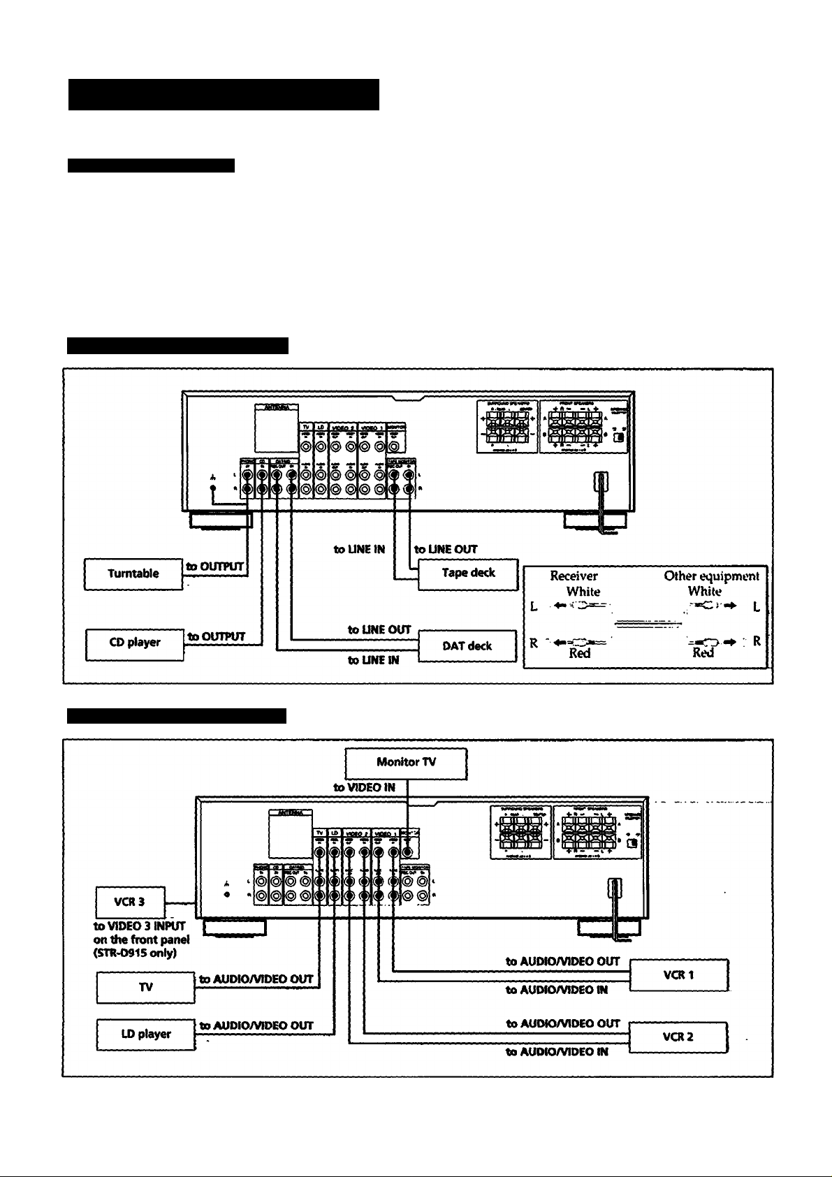
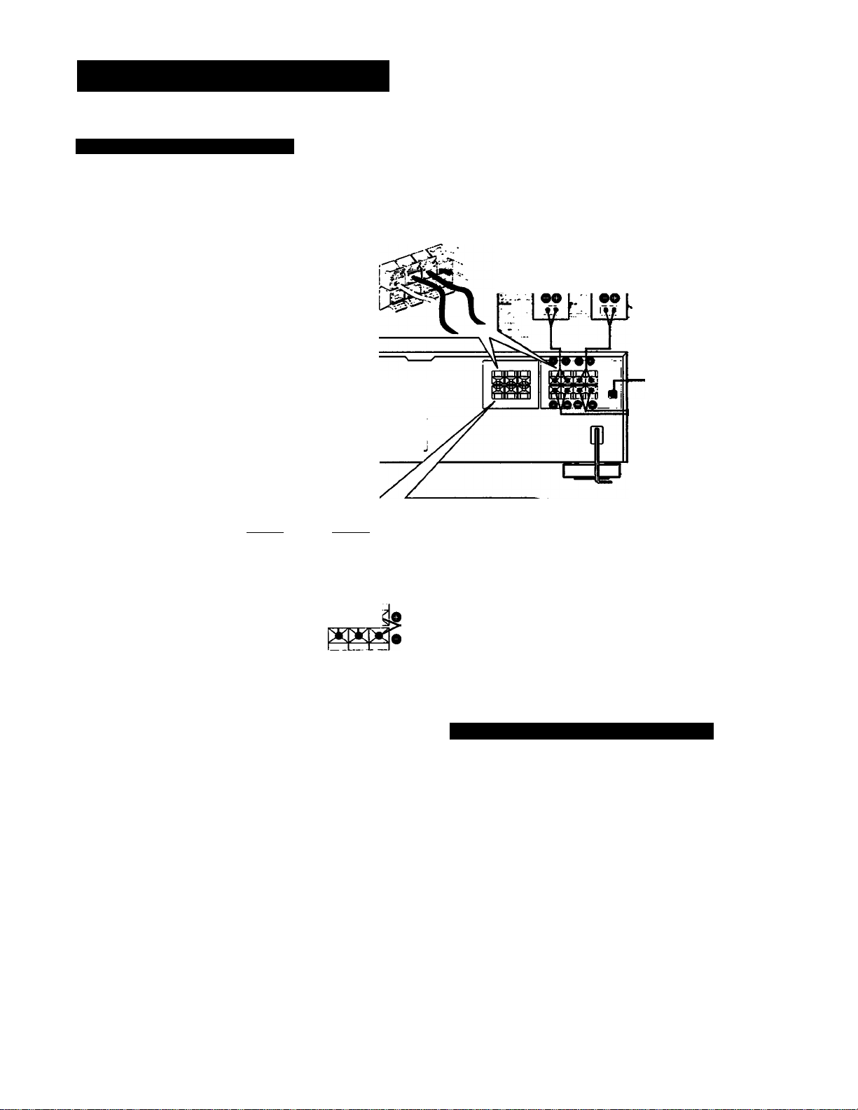
Hooking Up the System
Notes on Connections
At first, this section describes about the connection with the other equipments, the antenna connection,
speaker connection and then the AC power connection.
• Do not connect the power cord to an AC wall outlet until you complete other connection.
• The cable connectors should be fully inserted into the jacl«. Loose connection may cause hum and noise.
• Jacks and plugs of the connecting cord are color*coded as follows:
Red jacks and plugs: For the right channel of audio signals
White jacks and plugs: For the left channel of audio signals
Yellow jacks and plugs: For video signals
Connecting Audio Equipment
Connecting Video Equipment
Page 7
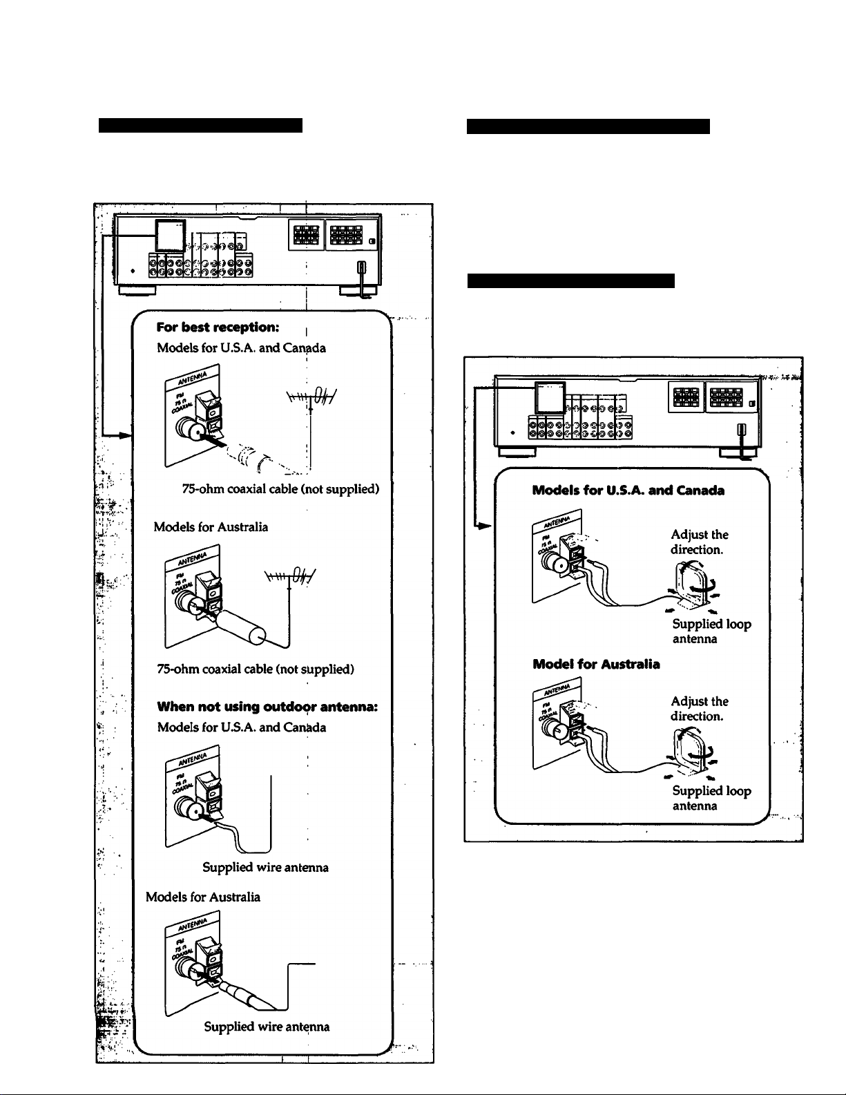
Connecting an FM Antenna
Connecting the Antenna Ground
Though the wire antenna is supplied with this unit, the
higher quality sound will be obtained with the 75-ohm
coaxial cable, (not supplied)
To prevent hum, connect the ground wire to ANTENNA
ground terminal (/k).
When an outdoor antenna is installed, be sure to connect the
ground wire for lightning protection.
Connecting an AM Antenna
The AM broadcast is adequate with the supplied AM loop
antenna. However, the connection of insulated wire is also
available for areas with difficult AM reception.
AM antenna extension
For best reception, attach a length of insulated wire (6 -15 m
long) to the AM ANTENNA terminal in addition to the loop
antenna.
Page 8
Hooking Up the System
Connecting Speaker Systems
You can connect front, rear and center speakers to this unit.
Approx.15 mm
C/,finches)
' Twist.
®®®®®®
Rear Rear
speaker (R) speaker (L)
W-
^^£ront Front
i^r^peaker (R) speaker (L)
IMPEDANCE selector
«TR-D915ordy)
i-«#’to tfie second
front speaker
system
Center
speaker
On the IMPEDANCE selector (STR-D915 only)
The STR-D915 has the IMPEDANCE SELECTOR for front
speakers.
When using the front speakers having nominal impedance
from 4 ohms or higher, set to the 4 D position.
When using the front speakers having nominal impedance
from 8 ohms or higher, set to the 8 D position.
Note
Use the front speakers having nominal impedance of more
than 8 ohms in the SURROUND mode.
Note
When connecting the speaker cord to the speaker terminal,
make sure that the polarity (+ and -) of the speaker cord is
correct. If the polarity is reversed at either speaker, the
sound will be distorted and will lack bass.
8
Connecting to the AC Power Outlet
Connect the AC power cord to the wall outlet last of all.
By connecting the power cord of the other audio equipment
to SWITCHED AC OUTLET, this unit can supply the power
source to the other audio equipment.
Caution
Be careful that the total power consumption of each
equipment connected to the outlets on the receiver does not
exceed 120 watts (for U.S.A. and Canadian models) or 100
watts (for Australian model).
Do not connect electrical home appliances such as an electric
iron, fan, TV, or other high-wattage equipment to these
outlets.
Page 9
uiapwi Æ. DaMC w|M$rciuwn
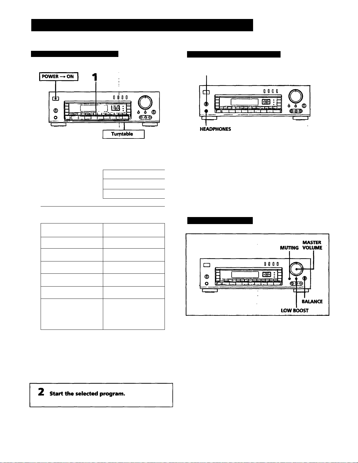
Listening toAA/atching a Program Source
Selecting a Program Source
1 Select the program source.
To listen to or watch
CD player
Tape deck
DAT/MD recorder
Tv 1
VCR
LO player
Press
Selecting the Speaker System
SPEAKERS
To drive speaker system A: Set SPEAKERS to A.
To drive speaker system B: Set SPEAKERS to B.
To drive both speaker systems A and B (series connection):
Set SPEAKERS to A+ B.
For headphone listening: Connect headphones to
HEADPHONES and set SPEAKERS to OFF.
IMPORTANT
Speaker systems A and B are connected in series. When only
one speaker system is connected, no sound can be heard at
..
...
■■
the A + B position.
Adjusting the Audio
Phono record
Radio Broadcast
PHONO
TUNER
Compact disc CD
DAT or MD program DAT/MD
Taped program
Video program
1
TAPE MONITOR
TV, LD, VIDEO!,
VIDEO 2
(and VIDEOS for
STR-D^15)
When a function selector is pressed, the indicator
of the function you have selected appears on the
display.
Select the function with the remote commander,
the power switches of both this receiver and the
selected equipment connected ito the AC outlets on
the receiver are turned on.
Adjusting volume
Turn MASTER VOLUME.
Reducing the sound to a low level temporarily
(- 20 dB attenuation)
Press MUTING. The indicator lights up.
Press again to restore the same listening level as before and
indicator goes off.
Adjusting the left and right sound balance
Adjust BALANCE to correct stereo imaging, when the
speaker position is not symmetrical.
Reinforcing the Bass
Press LOW BOOST so that LOW BCXDST indicator lights up.
Press again to turn off the effect.
Page 10
Listening toAAAatching a Program Source
Labeling the Program Source
You can create and input a name for each function button as
you like (except TUNER). You can use up to 11 letters for
each name.
1 Select the program source (except TUNER).
2 Press DISPLAY if "INDEX MODE* is not
displayed.
To Turn Off the Power at the Desired Time
(The Sleep Timer Function)
This function can be operated only with the remote
commander.
This receiver has the sleep timer function. With this
function, you can turn off the power automatically at the
desired time by designating the turn-off time.
Press SLEEP on the remote commander when the power is
on. Each time SLEEP is pressed, the designating time is
displayed in the following order;
2 hours —*• 1 hour and 30
minutes —► 1 hour —» 30 minutes —► SLEEP OFF.
When the sleep timer function is turned on, the display
becomes dim.
LEH»
Si
1 > 'J
'
i J / • —ij
' , . -Jj
1 j J li
LL,. ' 11 l!.‘
3 Press DPC MODE repeatedly until the INDEX
indicator lights up.
Create an index name.
To select a letter (A to Z) or number (1 to 9), press a
or V.
To change the position, press < or >.
Repeat steps 1 to 3 for ali other program
sources you want to assign an index name
to.
If you input an already stored source under any other index name
Only the last selected index name will be valid. Each
program source can be stored under only one index name.
i —i _i'
To change the turn-off time
1 Press SLEEP. The sleep time is displayed.
2 Press A or V to change the sleep time. The sleep time is
changed by 1 minute. It can be changed up to 5 hours.
To check the remaining time of the sleep timer
Press SLEEP. The remaining time is displayed.
To switch the original function name display and created index name display
Each time the DISPLAY is pressed, the selected function
name (which corresponds to the function selector) and the
created index name are alternately displayed.
10
Page 11
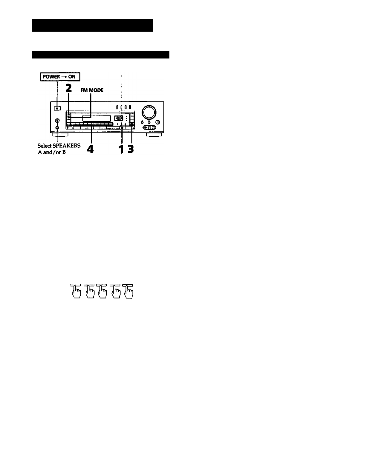
Receiving Broadcasts
Tuning in a Station Directly (Direct Tuning)
Press TUNER.
Press FM/AM to select FM or AM.
Press DIRECT.
4 Press the appropriate numeric buttons to
enter the frequency. (See examples below.)
The entered frequency is displayed.
To correct the entered frequency
Repeat steps 3 to 4.
If you enter a frequency not covered by the tuning interval
The entered value is automatically rounded up or down to
the closest value covered by the tuning interval.
Timing intervals for direct tuning are the followings:
FM: 50 kHz interval
AM; 10 kHz interval (for U.S.A. and Canadian modeb)
9 kHz interval (for Australian model)
(To switch the tuning interval between 9 kHz and 10 kHz,
see page 29.)
When the entered frequency does not exist in the
receivable frequency range
The entered digits (up to 5 digits for FM or up to 4 digits for
AM) blink in the frequency display area, and reception does
not take place.
If this occurs, press DIRECT again, and enter the correct
frequency. The frequency range of the receiver is 87.50 to
108.0 MHz for FM, and 530 to 1710 kHz with 10 kHz interval
(U.S.A. and Canadian models) or 531 to 1602 kHz with 9 kl-iz
interval (Australian model) for AM.
When an FM stereo program is noisy
When the unit receives an FM stereo program, the STEREO
indicator lights in the display window. If the stereo program
is noisy, press FM MODE to change the mode over to
MONO. This eliminates the stereo effect, but the noise will
be greatly reduced.
To retiUTi to the stereo mode, press FM MODE again.
Example 1: FM 102.50 MHz
1 0 2 5 0
Fm02. 50MH:
Example 2: AM 720 kHz
7 2
720 kH:
Note on AM tuning
You have to enter the last "0" for Australian model.
11
Page 12

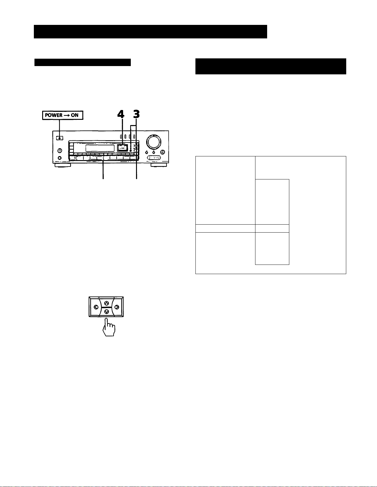
Receiving Broadcasts
Automatic Tuning
you do not know the frequency of the station, use
utomatic tuning.
POWER-»ON [
2 LEVEL
Select SPEAKERS
A and/or B
Press TUNER.
Press FM/AM to select FM or AM.
4 3
Presetting Stations
You'll most likely want to preset the stations you listen to
often. The receiver can store a total of 30 FM or AM stations.
Select SPEAKERS
A and/or B
Press TUNER.
Tune in the desired station.
(See "Direct Tuning" on page 11 or "Automatic
Tuning" in the left column.)
3 Press DISPLAY if the frequency is not
dispiayed.
4 Press INDEX SELECT/TUNING + or -.
For a higher frequency, press INDEX SELECT/
TUNING +.
For a lower frequency, press INDEX SELECT/
TUNING-.
When a station is received, automatic tuning stops
automatically. Press + or - until the desired station
is received.
' the automatic scan stops frequently or FM reception only)
0 receive only stations with strong signals, press LEVEL.
IGH appears on the display.
0 receive all receivable stations again (including stations
ith weaker signals),
ress LEVEL unHl HIGH goes off.
Press MEMORY.
"MEMORY” appears for a few seconds.
4 Press SHIFT to select the memory page (A, B
or C) while "MEMORY” is displayed.
Each time SHIFT is pressed. A, B or C appears
cyclically on the display.
5 Press the desired numeric button (1 to 0)
while "MEMORY" is displayed.
Repeat steps from 2 through 5 for presetting other
desired stations.
Use of memory pages
The memory pages (A, B and C) can be used to classify
stations according to the music category, station band, etc.
Replacing a preset station
Preset another station on the number of the station to be
replaced. The previously preset station will be erased.
IMPORTANT
The memorized station is maintained for approximately one
month even if the power cord is disconnected from the AC
wall outlet. If they are erased, store the stations again.
12
Page 13

Tuning in a Preset Station (Preset Tuning)
There are two ways to perform the preset tuning.
In method A (the direct tuning), select by designating the
desired preset station number directly with the numeric
buttons. In method B (the scan tvming), select the preset
station with the PRESET TUNING +/- button.
Method A: Direct tuning
Method B: Scan tuning
Select SPEAKERS
A and/or B
Press TUNER.
2 Press DISPLAY if the frequency is not
displayed.
Press TUNER.
2 Press SHIFT to select the memory page (A,
B, or C).
Each time SHIFT is pressed, A,B or C ap{>ears
cyclicallly on the display.
3 Press the numeric buttons jto designate the
desired preset station number.
3 Press PRESET TUNING + or-to select the
desired preset station.
For a higher preset number, press PRESET
TUNING +.
For a lower preset number, press PRESET
TUNING-.
Each time you press + or -, the preset station of the
next higher or lower number is tuned in.
A1
li
• If you keep pressing + or -, preset stations are
successively tuned in. Release the button when the
desired preset station is tuned in.
AO
CO
^ B1 ^ ^ BO
+
+
+
+
13
Page 14

Receiving Broadcasts
Labeling the Preset Stations (Station Index)
You can divide preset stations under index names you create
(up to 5 characters). If you want to categorize the preset
stations by kinds of music, for example, create indexes such
as ROCK, JAZZ, etc.
V t.'v; '
POWER-»oiTI
Select SPEAKERS
A and/or B
Press TUNER.
Tune in the desired station with Preset
Tuning on page 13.
If you store an already categorized station under
any other index name
Only the last selected category will be valid. Each station
can be stored under only one index name.
To display the frequency and index name of preset
stations
Each time DISPLAY is pressed, frequency and index name of
the preset station are alternately displayed.
Press DISPLAY if "INDEX MODE" is not
dispiayed.
4 Press DPC MODE repeatedly until the INDEX
indicator lights up.
Create an index name.
To select a letter (A to Z) or number (1 to 4), press A
or V.
To change the position, press < or >.
6 Repeat steps 2 through 4 for all other
stations you want to assign an index name
to.
14
Page 15

Selecting a Station among the Preset
Stations in the Index (Index Tuning)
Receiving FM Simulcast TV Programs
POWER-»ON
TV tuner or VCR | 3 *1L
Select SPEAKERS
A and/or B
Press TUNER.
Press DISPLAY to set to the INDEX mode.
When no index name is memorized, ”
appears on the display.
Select the desired station.
I
• To select a station in the same index:
For a higher preset number, press PRESET
TUNING +.
For a lower preset number, press PRESET
TUNING-.
______
CD
to VIDEO 1.
2 IN
(
.......
""
1 ffl
0 D 0 0
: 1=
to MONITOR
VIDEO OUT
6 A (ID
m
Select SPEAKERS
A and/orB
t—■ I
1 4 4
TV tuner or VCR [ 3
to VIDEOS IN
Select VIDEO 1, VIDEO 2. VIDEO 3 (STR-D915
only) or TV according to an equipment to
whi^ the VHF antenna is connected.
"VIDEO 1", "VIDEO 2", "VIDEO 3" or "TV" appears
on the display.
Turn on the monitor TV.
Select the desired program on the TV tuner or the VCR.
• To select a index station under other index name:
Press INDEX SELECT/TUNlKlG - or + to display
the desired index name. ;
For a higher preset number, press PRESET
TUNING +.
For a lower preset number, press PRESET
TUNING-.
4 Press TUNER and tune in the FM simulcast
TV program with a numeric button on the
receiver.
’IP I ^1 M M M ^
15
Page 16

I
Qiapter 2 Basic Operations
Remote Controls
Using the Remote
The remote lets you operate the connected components as
well as the receiver. Press one of the FUNCTION buttons
first to select the program source, then use the following
buttons to operate each component.
The FUNCTION buttons are factory set in the following list.
FUNCTION to be pressed
TUNER
TAPE
DAT/MD
TV
LD
VIDEO 1
VIDEO 2
VIDEO 3 (STR-D915 only)
CD
PHONO
Operating equipment
Tuner
Tape deck A
DAT deck
TV
LD player
VCR (VTRl mode)
VCR(VTR2mode)
VCR (VTR3 mode)
CD player
(The receiver enters the PHONO mode)
This remote commander can control Sony stereo cassette
deck having RMS function.
For more information on the availability of Sony stereo
cassette deck with RMS capability, contact your nearest Sony
dealer.
Turning on the power of each equipment
Operative buttons
For FM/AM tuner
To Press
Select memory pages for preset tuning
Designate preset numbers
Scan and select preset stations
Select station index names
SHIFT
Numeric buttons
CH PRESET*/INDEX
For tape deck/DAT/MD recorder
To
Designate numbers Numeric buttons
Designate number more than 10
(For tape deck and MD recorder)
Fastforward
Rewind
Skip selections (For DAT and MD recorder)
Pause play
Start play
Start reverse play (For tape deck)
Select the tape running direction (For tape
deck having RMS function)
Stop play
Clear the RMS program contents (For tape
deck having RMS function)
Start recording (Forward direction)
Start recording (Reverse direction for tapie
deck)
Program selections (For tape deck having
RMS function)
Press
>10
◄◄
II
►
RMS DIRECTION
■
RMS CLEAR
• *►
RMS/START
Press one of the SYSTEM CONTROL/FUNCTION buttons.
The receiver and the corresponding equipment are
turned on.
2 Operate the units with each button.
The buttons you can operate differ among function
mode. See "Operative Buttons”.
Turning off the power of equipments
By pressing the SYSTEM OFF button, you can turn off the
power of all equipments at one time.
Pressing the VISUAL POWER button would also turn off the
TV, VCR, LD player. When you want to turn off the power
while listening to a program source, see "Back ground
operation” on page 17.
For TV/VCR/LD player
To
Designate channel numbers of TV /VCR or
selections of LD player
Designate selections of LD player more than
10
Enter the selected TV/VCR.channel
Select TV to see TV programs and VIDEO to
see videos.
Select the output signal from the antenna
terminal on the VCR: a TV signal or VCR
program (For VCR)
Select a preset channel of TV or VCR
Fastforward (For VCR and LD player)
Rewind (For VCR and LD player)
Pause play (For VCR and LD player) II
Start play (For VCR and LD player) ►
Stop play (For VCR and LD player)
Skip selections (For LD player)
Start recording (For VCR)
Turn on the power ofTV, VCR, or LD player \TSUAL POWER
Pr«s$
Numeric buttons
>10
ENTER
TV/VIDEO
ANTTV/VTR
CH PRESET */►►
«
■
• *►
16
Page 17

For CD player
To
Designate numbers Numeric buttons
Designate number more than 10
Skip discs
Search selections '
Skip selections
Pause play '
Start play
Stop play ,
Press
>10
D.SKIP
II
►
■
If you use Sony TV
When you press the VIDEO 1,2,3 (ST1R-D915 only), TV or
LD button, the power of the lV (VCR or LD player) is also
turned on.
When an LD player or VCR is selected, the input of TV
switches to VIDEO, and when TV is sélected, the input of TV
switches to TV reception mode. (When you want to turn on
the power of TV and switch the TV input simultaneously,
keep pressing the button you have selected imtil its power is
turned on, or press the button again after the TV is turned
on.)
If the TV input does not switch to the appropriate mode,
switch the input signal by pressing the lV/VIDEO button.
If you use TV most of the time (Only for Sony TV)
You set the remote to operate only the'TV. Press the TV
CONTROL ON button. The remote biittons would work
only with TV. When you press it, the TV turns on and
switches to TV reception mode automatically.
(When you want to perform the turning on the power of TV
and the switching of the TV input sim^taneously, press the
TV CONTROL ON button until its power is turned on, or
press the button again after the TV is t|imed on.)
If the TV input does not switch to the appropriate mode,
switch the input signal with the TV/VIDEO button.
Changing the Settings of the FUNCTION
Buttons
You can replace the functions stored in the FUNCTION
buttons.
Hold down one of the FUNCTION buttons you want to
change and press one of the numeric (1 to 0) buttons to select
the desired Unction.
After changing the setting of the FUNCmON button, the
equipment can be operated with the FUNCTION button you
have changed.
To return the function to the initial mode, perform the same
operation above.
With the numeric buttons from 1 to 0, each function can be
selected as described in the following table:
Numeric buttons
1
2
3
4
5
6
7
8
9
0
The function to be selected
CD player
DAT deck
MD recorder
DECK A
DECKB
LD player
VCR 1 (Remote control mode)
VCR 2 (Remote control mode)
VCR 3 (Remote control mode)
TV
Example: To change the CD FUNCTION button to the DAT
function button.
Back ground operation
You can temporarily operate other coiAponents while
listening to/watching a program source.
Press one of the numeric button* in which a function is
stored and an operation button at the same time while
pressing BACK GROUND button. The operative buttons are
VISUAL POWER, TV/VIDEO, CH PRESET +/-, ANT TV/
VTR, D.SKIP, ►, ■, ► «, M^, II, •.
Example: To record the CD being played on tapes.
* For stored functions in numeric buttons, see the table in
"Changing the Settings of the FUNCTION buttoi«”.
Note
You can record only in the forward direction with back
ground operation.
Note
The settings of the TUNER button and the PHONO button
cannot be changed.
17
Page 18

I Chapter 3 Advanced Operations
Recording an Audio Source Editing a Video Source
Recording on a Tape
You can record and make copies of audio program sources
on a tape, DAT or MD using the receiver. See your tape
deck, DAT deck or MD recorder’s instruction manual if you
need help.
¡■yrgsfcir V ■■ -m-iv.-i
■=t> Audio signal flow
1 Press a function button to select the
recording source.
Recording on a Video Tape
You can record and make copies of programs from other
VCR, LD player or TV using the receiver. See your VCR, LD
player or TV’s instruction manual if you need help.
’ Signal flow
STR-D915 only
2 Set the recording source to be ready for
playback.
For example, tune in the desired station for an FM/
AM broadcast.
3 Insert a blank tape into the recording deck
and adjust the recording level, if necessary.
4 Start recording on the recording deck and
then start playing the recording source.
Note
When you record on a DAT deck or MD recorder coimected
to the DAT/MD RFC OUT jacks, the sound field and low
boost settings have no effect on recording.
You can monitor the sound being recorded on a
tape
If you have connected a 3-head tape deck to the TAPE
MONITOR jacks, press TAPE MONITOR while recording or
dubbing, so that the TAPE MONITOR indicator lights up
and you can monitor the recording results. To listen to the
source sound, press the button again until the indicator goes
off.
1 Press a function button to select the
recording source.
Set the recording source to be ready for
playback.
For example, insert a source tape you want to record
from into the playback VCR.
3 Insert a blank video tape into the recording
VCR.
4 start recording on the recording VCR and
then start playing the recording source.
18
Page 19

Adding New Sound on a Video Tape during
Video Editing
You can record audio from various audio program sources
while recording video, LD or TV pro^ams on a video tape
instead of their original sound. See your VCR, LD player or
TV’s instruction manual if you need help.
Video signals flow
f=^ Audio signals flow
2.6
!5
To record other audio on a desired part of video
After step 5, play back the \ddeo recording source and press
the pause button on it at the point where you want to record
other audio.
Start recording on the recording VCR, release the pause
mode and start playing the audio recording source.
Press a function button to ^select the video
recording source
2 Set the video recording soiirce to be ready
for playback.
3 Press a function button to jseiect the audio
recording source.
4 Set the audio recording source to be ready
for playback.
5 Insert a blank video tape into the recording
VCR.
G Start recording on the recording VCR and
then start playing the both video and audio
recording source.
19
Page 20

Obtaining the Surround Sound
This section describes about selecting the speaker
configuration and then adjusting the speaker volume and
the delay time of the rear speakers so that you can enjoy the
Dolby surround sound.
Placement of Speakers and Selecting the
CENTER MODE for Dolby Surround Sound
The Dolby Pro Logic Surround Decoder has the same
functions for playback as movie theaters and gives a
theater-like experience in your listening room, naturally
reproducing the audio sound field.
The STR-I5915/D715 incorporates a decoder which
reproduces the specially encoded surround sound of Dolby
surround video programs.
In the DOLBY SUR or THEATER mode, select the speaker
operation mode according to your speaker configuration by
pressing the CENTER MODE button. Each time the
CENTER MODE button is pressed, the CENTER MODE is
changed in the following order:
[»»PHANTOM3CH LOGIC NORMAL-»»WIDE
□
3CH (Channel) LOGIC mode
Select this mode when you play back a Dolby surround
program source only with the front and center speakers. The
sound of the rear channel is output from the front (L and R)
speakers.
Center speaker
Front speaker (R)
NORMAL mode
Select this mode if you use a small center speaker. The bass
sound of the center channel is output from the front
speakers, as a small speaker cannot produce enough bass.
Center
Front speaker (L) speaker Front speaker (R)
PHANTOM mode
Select this mode when you play back a Dolby surrotmd
program source without using a center speaker. The sound
of the center channel is output from the front (L and R)
speakers.
Front speaker (L)
Rear speaker(L)
Front speaker (R)
^37"
Rear speaker (R)
y B
Q
Rear speaker (L)
WIDE mode
Select this mode if you use a medium to big center speaker.
Rear speaker (R)
20
The Dolby Pro Logic Surround Decorder is a system to
decord the software carrying the DDi»*»»«—»«amark.
Page 21

Adjusting the Speaker Volume
To enjoy surround sound to the maxiilrium on playing any
program source, adjust the front, rear; and center (if
connected ) speakers to the same volume level. The level
once adjusted can be used for all surround modes.
You can adjust the volume level from jyour listening position
by using the remote commander.
iaMM8iia«g!Kr!ii:8Ba£a
5 Adjust the volume level so that the sound
from each speaker will be the same level at
the listening position.
To adjust the level of center speaker
Press CENTER LEVEL +/- on the remote
commander.
To adjust the level of rear speakers
Press REAR LEVEL +/- on the remote commander.
12 3 5
1 Press SOUND FIELD ON/OFF to ON.
The last selected sound field indicator lights.
2 Press SOUND FIELD MODE repeatedly until
DOLBY SUR indicator lights.
ACOUSTIC
DLBY SUR
THEATER
□ LIVE
□ HALL
□ DANCE
When operating with buttons on the front panel.
To adjust the level of center speaker
Press A or V.
To adjust the level of rear speakers
Press < or >.
(When adjusting the VOLUME control on the
receiver, all speakers are adjusted
simultaneously.)
6 Press TEST TONE on the remote commander
to set to off.
Sequence of the test tone
In a system with a center speaker:
The test tone will be heard automatically from the front L,
center, front R, and the rear speakers in succession.
Front left
Center
t3CH LOGIC j
NORMAL and WIDE modes
Rear left and right
In a system without a center speaker:
The test tone will be heard automatically from the front left
and right speakers and the rear speakers alternately.
Front right
Press CENTER MODE on the front panel
repeatedly until a desired inode (PHANTOM,
3CH LOGIC NORMAL or WIDE) is displayed.
The mode should be selected according to your
speakers system.
4 Press TEST TONE on the remote commander.
The test tone is heard from each speaker
sequentially.
The receiver is preset in the factory to get an optimum
surround level as long as each speaker has an equal
efficiency. 2^
Page 22

Obtaining the Surround Sound
Adjusting the Delay Time of the Rear
Speakers
— for DOLBY SUR (Dolby surround) mode
The delay time is a time between the surround sound from
the front and that from rear speakers. The delay time is
adjustable from 15 ms to 30 ms. For the adjustable range of
the delay time except for the DOLBY SUR mode, see page 23.
4 12 3
To turn off the surround effect
Press SOUND HELD ON/OFF to OFF.
The sound without surround effect will resume.
The settings of the center and rear level and the delay time
are not cleared until you change the settings. They will be
recalled whenever you select a sound field program.
Note
The delay time for the rear speakers can be adjusted even in
the 3CH LOGIC mode.
1 Press SOUND FIELD ON/OFP to ON.
The last selected sound field indicator lights.
2 Press SOUND FIELD MODE repeatedly until
the DOLBY SUR indicator lights.
3 Press DPC MODE repeatedly until the SUR
(surround) indicator lights.
Press A or V to select the delay time mode.
Press < or > to adjust the delay time.
22
Page 23

Sound Field Settings
Available Type of Effects
6 recommended sound ñeld program^ (combination of the settings of the surround and tone control.) have been preset in the
factory. Since these programs are appropriate for the most type of music and listening situations, you can enjoy the sound effect
by selecting the desired sound field program according to the program source. And you can also manipulate various
parameters to finely tune the factory-preset settings to your room, or create original sound effects as you like.
'^^^und field
Parameter^^-^^^
Tone
?
Il
DOLBY SUR: Decodes programs processed with the Dolby
THEATER: Adds the reflection of a theater to decoded
signals of the Dolby pro logic decoder.
LIVE: Reproduces the acoustics of a latge concert hall. It is
HALL: Reproduces the acoustics of a rectangular concert
DANCE: Boosts high and low frequencies and the dynamic
Delay time
Rear level
Center level
surround. i
effective for playing a program source with hard sound.
hall with soft sound.
sotmds are reproduced.
dolbV sur
• -
• •
THEATER
• •
• •
• •
UVE
HALL
•
•
•
DANCE ACOUSTIC
• •
•
•
ACOUSTIC: The surround effect is defeated and only the
tone control is available.
Adjusting the delay time of the rear speakers
(Except for DOLBY SUR mode)
THEATER, UVE, HALL, DANCE : 5 -30 ms.
Page 24

Sound Field Settings (Continued)
Adjusting the Sound Field Programs
Adjusting the tone control
4 12 3
1 Press SOUND FIELD ON/OFF to ON.
The last selected sound field indicator lights.
2 Press SOUND FIELD MODE repeatedly until
the desired SOUND FIELD program is
displayed.
3 Press DPC MODE repeatedly until the TONE
indicator lights.
Adjusting the surround sound parameters
•mm
5 1 234
1 Press SOUND FIELD ON/OFF to ON.
The last selected sound field indicator lights.
2 Press SOUND FIELD MODE repeatedly until
the desired SOUND FIELD program is
displayed.
If you select DOLBY SUR or THEATER on step
2. press CENTER MODE to select PHANTOM,
3CH LOGIC NORMAL or WIDE.
Press < or > to select BASS or TREBLE.
5 Press A or V to adjust the level.
To cancel the tone effect
Press TONE ON/DEFEAT on the front panel or EQ/TONE
ON/OFF on the remote commander. The sound processed
only with the surround settings is heard.
4 Press DPC MODE repeatedly until the SUR
(surround) indicator lights.
5 Press A or V to select the desired
parameter (delay time, rear or center level).
6 Press < or > to adjust the level of the
parameter.
After setting the surround program, the setting is
stored automatically.
When you store a new sound field effect
The previous sound field effect is erased and the new one
will be replaced.
Even if AC power cord is disconnected
The stored data is maintained for approximately 1 month.
When selecting ACOUSTIC
ACOUSTIC does not have the surround effect and only the
tone effect can be available. So when selecting ACOUSTIC,
only the tone setting can be adjusted.
Note
Only one sound field program will be stored in a function.
Each time you select the function, the sound field program
previously stored in the function will be called up.
24
Page 25

Calling up the Sound Field Setting
2
1
IP
Uo
a
- I I ;
(ID
o №
I Press SOUND FIELD ON/OFF to ON.
The last selected sound field indicator lights.
^
. il l C ©
2 Press SOUND FIELD MODE repeatedly
until the desired SOUND FIELD program is
displayed.
Restoring to the setting stored at the factory
Press POWER while pressing TONE ON/DEFEAT on the
front panel. All of the 6 settings are then restored.
25
Page 26

s|#wt •» wMt««
Troubleshooting Guide
Before proceeding through the check list below, examine the connections and the procedures
outlined in the manual.
Should any problem persist after you have checked the following items, consult your nearest
Sony dealer.
Problem
No FM station can be located by
Automatic tuning operation.
The STEREO indicator flickers or does
not appear when receiving stereo
programs.
No station can be tuned in by
Automatic tuning operation.
No stations can be tuned in with scan
tuning.
No sound is heard even if you adjust
VOLUME.
Cause Solution
The signal strength of the stations is
too weak.
A very weak FM station or a noisy FM
program is received.
The AM tuning interval is set
incorrectly. (For U.S.A. and Canada
models)
The signal strength of the station is too
weak for Automatic tuning.
No stations have been preset.
The speaker or program source
equipment is not connected correctly.
Press TUNING LEVEL to sot the
receiving signal level low.
Check the antenna connection.
Adjust the antenna or connect an
external FM antenna.
Press FM MODE to set to MONO
mode.
Change the tuning interval according
to the AM frequency allocation system
of your country. (See page 29)
Adjust the antenna.
Directly tune in the stations.
(See page 11)
Preset the stations. (See page 12)
Connect the equipment correctly.
Sound is heard oiUy at a very low
volume.
One channel does not transmit audio,
or the volume from the left and right
speakers is unbalanced.
The SPEAKERS selector is not set
correctly.
The TAPE MONITOR button has been
pressed. (The indicator is lit.)
A wrong function selector has been
pressed.
The function switch on the VCR is not
set correctly.
MUTING has been pressed. (The
MUTING indicator is lit.)
The BALANCE control is not set
appropriately.
The speaker or program source is not
connected correctly.
Set the selector correctly.
Press the button so that the indicator
goes out. The tape monitor function
will be canceled.
Press the correct function selector.
Check and set it correctly.
Press the button to cancel the muting
function.
Adjust the BALANCE control.
Check and properly connect the
equipment.
26
Page 27

Problem
Cause
Solution
There is an abrupt loss of sound from 1
one or both of the speakers/ and the
PROTECTOR indicator flickers on the
display.
Sound transmitted from the speakers i
is reversed.
There is lack of bass sound or the :
instrument position is obscure.
Severe hum or noise is heard.
■
A short-circuit problem activates the
protective circuit.
The speakers are not connected
correctly.
The ©/© connection of the speaker is
reversed.
The connecting cords are not shielded
type.
A transformer, motor, TV or
fluorescent light affects the connecting
cords.
The audio components are too close to
a TV set.
The unit is not grounded.
Turn off the unit, eliminate the shortcircuit problem and turn on the power
again. If there is no short-circuit
problem, consult your nearest Sony
dealer.
Connect the right speaker to the R
SPEAKER terminals and the left
spéaker to the L SPEAKER terminals.
Connect the speaker with the correct
phase.
Use shielded type cords.
Place the connecting cords in a
location away from a transformer or
motor, and at least 3 meters (10 feet)
from a TV set or a fluorescent light.
Place TV away from the audio
components.
Connect the ground wire to the
antenna ground terminal.
No sound or sound at very low level is'
heard from rear speakers.
Surround effect cannot be obtained.
The remote commander will not
operate.
The connections are loose.
The plugs and jacks are dirty.
The SOUND FIELD circuit is turned
off.
The CENTER MODE button is set to
3CH LOGIC.
The SOUND FIELD circuit is turned
off.
The batteries are exhausted.
The commander head is not pointed
toward the unit's front.
The mode of the remote commander is
not the same as the receiver.
Make secure connections.
Wipe the plugs and jacks with a cloth
lightly dampened with alcohol.
Press SOUND HELD ON/OFF to ON.
Set it to WIDE, PHANTOM or
NORMAL according to your speaker
system.
Press SOUND HELD ON/OFF to ON.
Replace the batteries with new ones.
Point the commander head toward the
receiver.
Press the desired FUNCTION button
on the remote commander again.
27
Page 28

Specifications
(For U.S.A. and Canadian models)
Audio Power Specifications
POWER OUTPUT AND TOTAL
HARMONIC DISTORTION
With 8-ohm load, both channels
driven, from 20 - 20,000 Hz, rated 110
watts (STR-D915) or 100 watts (STRD715) per channel minimum RMS
power, with no more than 0.3 % total
harmonic distortion from 250
milliwatts to rated output.
(U.S. A. model only)
other Specifications
Amplifier section
Continuous RMS power output (8 ohnis, at 20 Hz - 20 kHz less than
0.3 % total harmonic distortion) (FRONT)
STR-D915:118W+118W
STR-D715:110W + 110W
Surround mode
Surround mode (8ohms at 1 kHz, THD 0.8 %)
STR-D715
80W/ch
80W
25W
FRONT
CENTER»
REAR
STR-D915
lOOW/ch
100 W
25W
* (only in theDOLBY SUR and THEATER modes)
Ovnamic power output
STR-D915: 160 W + 160 W (8 ohms)
STR-D715: 155 W + 155 W (8 ohms)
Harmonic distortion at rated output
Frequency response PHONO: RIAA equalization curve
Inputs
PHONO
(MM)
CD
DAT/MD,
TV, LD,
VIDEO 1,2,
3»,TAPE
MONITOR
Outputs
REC OUT VIDEO 1,2
(AUDIO) OUT
HEADPHONES
MUTING
LOW BOOST
TONE
225 W + 225 W (4 ohms)
220 W + 220 W (4 ohms)
Less than 0.3 %
±0.5 dB
CD, DAT/MD, TAPE MONITOR,
VIDEO 1,2.3»: 10 Hz - 50 kHz .‘¡'dB
Sensitivity
2.5 mV
300 mV
250 mV
Impedance
50 kilohms
50 kilohms 82dB/82dB
50 kilohms 82dB/82dB
Voltage 250 mV
Impedance 10 kilohms
Accepts low and high impedance
headphones
-20 dB
+10 dB at 70 Hz
±8 dB at 100 Hz and 10 kHz
S/NShort ANct/78
IHFANet
75dB/75dB
♦STR-l»15only
*STR-D915only
28
Page 29

FM tuner section
Tuning range
Antenna terminals
Sensitivity (at 50 dB):
Usable sensitivity
S/N
Harmonic distortion at 1 kHz
Separation
Frequency response
Selectivity
87.5-108.0 MHz
75 ohms, imbalanced
18.3 dBf, 4.5 pV (mono)
38.3 dBf, 45 pV (stereo)
11.2dBf,2pV(lHF)
Mono: 76 dB
Stereo; 70 dB
z
Mono; 0.3 %
Stereo: 05 %
45dBatlkHz
30Hz-15kHz*“dB
60 dB at 4001kHz
AM tuner section
Tuning range
Antenna
Usable sensitivity
S/N
Harmonic distortion
Selectivity
You can change the AM tuning interval to 9 kHz. After tuning in
any AM tuning in any AM station, tum'off the power of receiver
once. While holding down the TUNING + button, press the
POWER switch. When you change the interval, all the preset
stations will be erased. To reset the interval, repeat the same
procedure.
530 -1710 kHz (with 10 kHz interval*)
531 -1710 kHz (with 9 kHz interval)
Loop antenna
50 dB/m (at 1,000 kHz or 999 kHz)
54dB(at50mV/m)
0.5%(50mV/m,400Hz)
35 dB (9 kHz), 40 dB (10 kHz)
Video section
Inputs
Outputs
STR-D915: VIDEO 1,25:
1 Vp-p 75 ohms
STR-D715: VIDEO 15:
1 Vp-p 75 ohms
VIDEO 1,2, MONITOR:
1 Vp-p 75 ohms
Generai
S)rstem
Preamplifier section
Power requirements
Power consumption (in standby condition: 5W)
AC outlets
Dimensions
Mass
Supplied accessories
Design and specifications are subject to change without notice.
Tuner section: PLL quartz-locked
digital s)mthesizer system
Low-noise NF type equalizer
Power amplifier section: Pure
complimentary SEPP
120 VAC, 60 Hz
STR-D915:USA model: 210 W
Canada model: 305 VA
STR-D715:USA model: 195 W
Canada model: 280 VA
Two switched, total 120 W
430 X148 X 355 mm
(17 X 5 V, X14 inches)
STR-D915:10.0 kg (22 lb 1 oz)
STR-D715:9.7 kg (22 lb 7 oz)
FM wire antenna (1)
AM loop antenna (1)
Remote commander (1)
Sony Batteries SUM-3(NS) (2)
29
Page 30

Specifications
(For Australian model)
Amplifier section
Continuous RMS power output (8 ohms, at 20 Hz - 20 kHz less than
0.7 % total harmonic distortion) (FRONT)
110 w +now
Surround mode
Surround mode (8 ohms at 1 kHz, THD 0.8 %)
FRONT; lOOW/ch
CENTER»: 100 W
REAR: 25 W
Frequency response
Inputs
PHONO
(MM)
CD
DAT/MD,
TV,LD,
VIDEO 1,2,3,
TAPE
MONITOR
Outputs
REC OUT VIDEO 1,2
(AUDIO) OUT
HEADPHONES
MUTING
LOWB(X>ST
TONE
»(only in theDOLBY SUR and THEATER modes)
PHONO: RIAA equalization curve
±0.5 dB
CD, DAT/MD, TAPE MONITOR,
VIDEO 1 A 3:10 Hz - 50 kHz** dB
Sensitivity Impedance S/NShortANel/'78
2.5 mV
300 mV 50kilohms
250 mV
50kilohms 75dB/75dB
50kilohms 82dB/82dB
Voltage 250 mV
Impedance 10 kilohms
Accepts low and high impedance
headphones
-20 dB
+10 dB at 70 Hz
±8 dB at 100 Hz and 10 kHz
IHFANet
82dB/82dB
FM tuner section
Tuning range
Antenna terminals
Sensitivity (at 46 dB):
Usable sensitivity
S/N
Harmonic distortion at 1 kHz
Separation
Frequency response
Selectivity
87.5-108.0 MHz
75 ohms, unbalanced
18.3 dBf, 4.5 pV (mono)
38.3 dBf, 45 pV (stereo)
11.2dBf,2pV(IHF)
Mono: 70 dB
Stereo; 66 dB
z
Mono: 0.3 %
Stereo: 0.5 %
45dBatl kHz
30Hz-15kHz!;| dB
60 dB at 400 kHz
AM tuner section
Tuning range
Antenna
Usable sensitivity
S/N
Harmonic distortion
Selectivity
531-1602 kHz
Loop antenna
so dB/m (at 1 Д)0 kHz or 999 kHz)
54 dB (at 50 mV/m)
0.5%(50mV/m,400Hz)
35 dB (9 kHz), 40 dB (10 kHz)
Video section
Inputs
Outputs
VIDEO 1,2,3:1 Vp-p 75 ohms
VIDEO 1,2, MONITOR:
1 Vp-p 75 ohms
General
System
Preamplifìer section
Power requirements
Power consumption (in standby condition: 5W)
AC outlets
Dimensions
Mass
Supplied accessories
Tuner section; PLL quartz-locked
digital synthesizer system
Low-noise NF type equalizer
Power amplifier section; Pure
complimentary SEPP
240VAC50HZ
220W
One switched, 100 W
430 x148 x 355 mm
(17 X 5 ’/, X14 inches)
10.0 kg (22 lb loz)
FM wire antenna (1)
AM loop antenna (1)
Remote commander (1)
Sony Batteries SUM-3(NS) (2)
30
Design and specifications are subject to change without notice.
Page 31

Identifying the Parts and Controls
Front Panel
[H POWER switch
[H FM MODE button (See page 11.)
[3] FM/AM button (See pages 11,12.)
Q] Remote sensor
\5\ STANDBY indicator
(The STANDBY indicator lights up when the power cord
is connected.: STR-D915 for Australian model only)
d] LEVEL button (See page 12.)
|T| Display window
d] Numeric buttons (See pages 11,12,13,15.)
d] INDEX SELECT/TUNING */- buttons
(See pages 12,15.)
M PRESET TUNING +1- buttons (See pages 13,15.)
O DIGITAL PROCESSING CONTROL buttons (See
pages 10,14,21,22,24.)
m SOUND FIELD ON/OFF button (See pages 21,22,24,
25.)
m SOUND FIELD MODE button (See pages 21,22,24,
25.)
Si CENTER MODE button (See pages 20,21,24.)
Si TONE ON/DEFEAT button (See pages 24,25.)
01 DPC MODE indicators
M DPC MODE button (See pages 10,14,21,22,24.)
01 DISPLAY button (See pages 10,12,13,14,15.)
01
MASTER VOLUME control (See page 9.)
M BALANCE control (See page 9.)
LOW BOOST button and indicator (See page 9.)
M VIDEO 3 INPUT jacks (STR-D915 only)
M MUTING -20 dB button and indicator (See page 9.)
M SHIFT button (See pages 12,13.)
H DIRECT button (See page 11.)
^ Function selectors and TAPE MONITOR button
and indicator (VIDEO 3 button: STR-D915 only)
(See pages 9,10,18.)
M MEMORY button (See page 12.)
M HEADPHONES jack
M SPEAKERS selector (Seb page 9.) 3 ^
Page 32

Identifying the Parts and Controls
Remote Commander (Except for The STRD915 for Canadian Model)
F»1
lliL-JCD
f=n
OB-
CD CD
CZI □
-m
42
-m
01
SOUND FIELD ON/OFF button (See pages 21,22,24,
25.)
01
TEST TONE button (See page 21.)
01
SOUND FIELD MODE W- buttons (Sec pages 21,22,
24,25.)
01
MASTER VOL buttons (Sec page 9.)
01
MUTING button (See page 9.)
01 LOW BOOST button (See page 9.)
01
CENTER LEVEL buttons (See page 21.)
01-
01
-
03 -
01
-
[U SYSTEM OFF button (See page 16.)
d] SYSTEM CONTROUFUNCTION
TAPE, DAT/MD, CD, TUNER, PHONO, VIDEO 1
VIDEO 2, VIDEO 3, LD, TV buttons (See pages 9,16,
18.)
-U
-J '
-m
-0 3_
01
REAR LEVEL buttons (See page 21.)
^ DIGITAL PROCESSING CONTROL buttons (See pages
10,14,21,22,24.)
M OPC MODE button (See pages 14,21,22,24.)
M RMS CLEAR, ■ button (See page 16.)
M BACK GROUND button (See page 17.)
^ ► , RMS DIRECTION buttons (Sec page 16.)
51 ► ► button (See pages 16,17.)
^ > 10, SHIFT button (See pages 16,17.)
53
Numeric buttons (1 to 0) (See pages 11,12,13,15.)
M TV CONTROL ON button (See page 17.)
^ SLEEP button (See page 10.)
[D VISUAL POWER button (See page 16.)
(H TV/VIDEO, INDEX button (See page 16.)
ID CH/PRESET buttons (See page 16.)
[6] RMS/START, ENTER button (See pages 16,17.)
[7] ANT TVA/TR. D (disc) SKIP button (See pages 16,17.)
ID button (See pages 16,17.)
ID # button (See pages 16,17.)
01II button (Sec pages 16,17.)
031EQ/TONE ON/OFF button (See page 24.)
32
Page 33

Quick Reference
When operate the unit consulting thisiQuick Reference, make sure that the unit and
the various audio/video equipment are properly connected.
Ex. Tuning in the FM station of 102.50 MHz
Directly tuning in an
FM or AM stгltion
j-<^
TUNER
15
FM^AM I
-0-
I
DIRECT
53 53 5
FM102.50MHz
33
Page 34

Quick Reference
INDEX
Labeling the preset
stations
Selecting a station
among the preset
stations in the index
r<H>
TUNER
15
£<®
Tune in a
TUNER
D T5
Select the station memorized
under the same index name.
INDEX SELECT/ TUNING
DISPLAY
"INDEX MODE" appears
on the display.
PRESET TUNING
b
34
Page 35

Adjusting the TONE
controls
Select the
desired
SOUND
FIELD
program.
TONE
- n-
DFCMODE
15
Select BASS or
TREBLE.
LEVEL
Adjusting the
surround setting
Select the
desired
SOUND
HELD
program.
SUR
DPCMODE
15
Select the
parameter.
\ Q ~/
“► ^
b Ò
LEVEL
35
 Loading...