

Page 1

3-755-128-23(1)
FM Steiw/FM-AM
Receiver
Operating Instructions
STR-D990
STR-D790
O 1992 by Sony Corporation
Page 2
s
ARNING
E
0 prevent fire or shock hazard, do not
xpose the unit to rain or moisture.
CA UT ION
RISK OF ELECTRIC SHOCK
A
CAUTION; TO REDUCE THE RISK OF ELECTRIC SHOCK.
DO NOT REMOVE COVER (OR BACK).
NO USER-SERVICEABLE PARTS INSIDE.
REFER SERVICING TO QUALIFIED SERVICE PERSONNEL.
This symbol is intended to alert the user to
the presence of uninsulated 'dangerous
voltage' within the product's enclosure that
may be of sufficient magnitude to constitute
a risk of electric shock to persons.
This symbol is intended to alert the user to
the presence of important operating and
maintenance (servicing) instructions in the
literature accompanying the appliance.
00 NOT OPEN I
This equipment generates and uses radio frequency
energy and if not installed and used properly, that is, in
strict accordance with the manufacturer's instructions, may
cause interference to radio and television reception. It has
been type tested and found to comply with the limits for a
Class B computing device in accordance with the
specifications in Subpart J of Part 15 of FCC Rules, which
are designed to provide reasonable protection against
such interference in a residential installation. However,
there is no guarantee that interference will not occur in a
particular installation. If this equipment does cause
interference to radio or television reception, which can be
determined by turning the equipment off and on, the user is
encouraged to try to correct the interference by one or
more of the following measures:
Reorient the receiving antenna
Relocate the equipment with respect to the receiver
Move the equipment away from the receiver
Plug the equipment into a different outlet so that
equipment and receiver are on different branch circuits.
If necessary, the user should consult the dealer or an
experienced radio/television technician for additional
suggestions. The user may find the following booklet
prepared by the Federal Communications Commission
helpful:
'How to identify and Resolve Radio-TV Interference
Problems'. This booklet is available from the U.S.
Government Printing Office. Washington, DC 20402, Stock
No. 004-000-00345-4.
NOTICE FOR THE CUSTOMERS IN THE UNITED
KINGDOM
>wner*s Record
lie model number is located on the rear exterior and serial
umber is on the rear. Record the serial number in the
oace provided below. Refer to these numbers whenever
DU call upon your Sony dealer regarding this product.
lodel No. Serial No.
Note to CATV system installer
This reminder is provided to call the CATV system
installer's attention to Article 820-40 of the NEC that
provides guidelines for proper grounding and, in
particular, specifies that the cable ground shall be
connected to the grounding system of the building, as
close to the point of cable entry as practical.
IMPORTANT
The wires in this mains lead are coloured in accordance
with the following code:
Blue: Neutral
Brown: Live
As the colours of the wires in the mains lead of this
apparatus may not correspond with the coloured markings
identifying the terminals in your plug-proceed as follows:
The wire which is coloured blue must be connected to the
terminal which is marked with the letter N or coloured black.
The wire which is coloured brown must be connected to the
terminal which is marked with the letter L or coloured red.
Do not connect either wire to the earth terminal in the plug
which is marked by the letter E or by the safety earth
symbol i or coloured green or green-and-yellow.
For the customers in Canada
i-CAUTION:
TO PREVENT ELECTRIC SHOCK. DO NOT USE THIS
POLARIZED AC PLUG WITH AN EXTENSION CORD.
RECEPTACLE OR OTHER OUTLET UNLESS THE
BLADES CAN BE FULLY INSERTED TO PREVENT
BLADE EXPOSURE.
This apparatus complies with the Class B limits for radio
noise emissions set out in Radio Interference Regulations.
------------------------------------------------------------------
Page 3

Table of Contents
Introduction
Overview
Precautions
IChapter 1 Getting Started
Unpacking
Hooking up the system
Parts identification...................................................... 10
I Remote commander (except for U.K. rhodel)
Chapter 2 Basic Operations
Operating with the remote commander......................13
I Changing the settings of the FUNCTION buttons
Adjusting basic audio controls
Selecting a program source
...........................................
..........................................,.....................
............................................i.....................
Choosing a good location..................................... 5
Checking the supplied accessories...;
Selecting the AM tuning interval
Inserting the batteries into the renxjte commander. 5
...............................................
Connecting audio equipment
Connecting video equipment
Connecting an FM antenna
Connecting an AM antenna
Connecting the antenna ground
Connecting speaker systems
Connecting to the AC power outlet
Front panel......................................|......................10
Adjusting volume................................................. 14
Adjusting left and right sound baiance
Adjusting tone from the front speakers;
Reinforcing the bass........................^...................14
Selecting the speaker system
..............;.....................
.....................................
;.......................4
....................
.............................
..........[......................
.................................
....................................
......
.......................
..........;......................
..........................
........
.......
..............\..................
..................
.................
...............................
12
14
14
14
15
\ To turn off the power at the desired time (The sleep
timer function)
Labeling the program source............;...................16
deceiving broadcasts
Tuning in a station directly (Direct tuning)
Scanning stations automatically (Auto tuning)
Presetting stations (Station preset)
Tuning in a preset station (Preset tuning)
Labeling the preset stations (Station index)............21
Selecting a station among the preset stations in the
I index (Index tuning).....................................i........................22
! Receiving FM simulcast TV programs ,....................22
jlecording an audio source
! Recording onto an audio tape deck or DAT deck
Tape dubbing
Editing a video source
Video tape dubbing
Adding new sound on a video tape during video
editing
................................................................
...............................1..................
............................
....................,...................
...................................!...................
..............................................
..........................;...................
1...................17
..............
.....
.......................
..............
.....
15
18
19
20
23
23
24
24
25
4
5
5
5
6
7
7
7
7
13
14
17
23
Chpater 3 Advanced Operations
Getting ready for Dolby surround sound....................27
Placement of speakers and selecting the
PRO LOGIC MODE............................................. 27
Adjusting the speaker volume
Adjusting the surround sound
Adjusting the delay time of the rear speakers
Sound field settings................................................... 30
Available type of effects........................................ 30
Adjusting the tone controls
6
8
9
Adjusting the sound field porgrams
Calling up the sound field setting
Linking the sound field memory to preset
stations or program source.................................32
Chapter 4 Other information
Troubleshooting guide
Specifications
Quick reference..........................................................37
............................................................
..............................................
..............................
...................................
........
..................................
.....................
..........................
28
29
29
31
31
32
33
35
Page 4

I
Introduction
Overview
The STR-D990/D790 is an FM Stereo/FM-AM receiver and
audio/video control center.
You can enjoy various audioA/ideo program sources with
this unit.
TV/video programs
• You can enjoy TV or CATV programs with FM simulcast.
• Sounds from various audio program sources can be
added on video tapes during editing.
Tuner
• Precise tuning is ensured by a quartz lock digital
synthesizer.
• Station index system allows you to tune into a station
quickly.
DOLBY PRO LOGIC
In the DOLBY or THEATER mode, the Dolby* Pro Logic can
be selected. The Dolby Pro Logic Surround Decoder has
the same functions for playback as movie theaters and
gives a theater-like experience in your listening room,
naturally reproducing the audio sound field.
• Manufactured under license from Dolby Laboratories Licensing
Corporation. Additionally licensed under one or more of the following
patents: US. numbers 3.632.886.3.746,792, and 3,959.590. Canadian
numbers 1.004,603 and 1.037,877. ’DOLBY" and the double-D symbol OD
are trademarks of Dolby Laboratories Licensing Corporation.
Sound field (combination of digital delayed surround and tone controls)
• 7 recommended sound field programs (DOLBY,
THEATER, LIVE, HALL, DISCO, SIMULATED, ACOUSTIC)
are preset in the factory for easy use. You can also store
up to 7 settings you created in the memory.
• Combined use of the sound field programs and the preset
stations or program source allow you to enjoy broadcast
or program source listening immediately with the
memorized 7 settings of sound field (DOLBY, THEATER,
LIVE, HALL, DISCO, SIMULATED, ACOUSTIC).
Precautions
On safety
• For U.K. model, operate the unit only on 240 V AC, 50/60
Hz.
• Operate the unit only on 120 V AC, 60 Hz.
• Should any solid object or liquid fall into the cabinet,
unplug the unit and have it checked by qualified
personnel before operating it any further.
• Unplug the unit from the wall outlet if it is not to be used
for an extended period of time. To disconnect the cord,
pull it out by grasping the plug. Never pull the cord itself.
• One blade of the plug is wider than the other for the
purpose of safety and will fit into the power outlet only
one way. If you are unable to insert the plug fully into the
outlet, contact your dealer, (except for U.K. model)
• AC power cord must be changed only at the qualified
service shop.
• This unit is not disconnected from the AC power source
as long as it is connected to the mains outlet, even if the
unit itself has been turned off.
On operation
Before making program source connections, be sure to
turn the power switch off and unplug the unit.
On cleaning the cabinet
Clean the cabinet, panel and controls with a soft cloth
lightly moistened with mild detergent solution. Do not use
any type of abrasive pad, scouring powder, or solvent such
as alcohol or benzine.
For the customers in the U.S.A.
For detailed safety precautions, see the “IMPORTANT
SAFEGUARDS" leaflet.
If you have any question or problem concerning your unit,
please consult your nearest Sony dealer.
Remote commander
• The supplied remote commander allows you to remotely
control this receiver and the equipments connected to the
receiver.
Page 5
I
Chapter 1 Getting Started
Unpacking
Choosing a Good Location
To prevent internal heat buildup in the unit,
place the unit in a location with adequate air circulation.
Do not Inatall the unit: '
• near heat sources such as radiators or: air ducts.
• in a place subject to direct sunlight, excessive dust,
mechanical vibration or shock. I
Do not place anything on top of the cabinet
The top ventiiation holes must be unobstructed for the
proper operation of the unit and to prolong the life of its
components. '
Do not throw away the carton and packing material!
It will be an ideal container when transporting the system for
repair work, etc.
Checking the Supplied Accessories
After unpacking, check that the followingiaccessories are
present.
• FM wire antenna.............................;....................(1)
• AM loop antenna
• Remote commander RM-U221
• Sony batteries SUM-3 (NS)
............................
.............
I
I
!....................(1)
.......
......................
!....................(2)
I
(1)
Selecting the AM Tuning Interval
The AM tuning interval is preset to 10 kHz. To use the
receiver where the frequency allocation system is based on
a 9 kHz interval, make the following adjustments.
1 Turn on the power and tune in any AM station.
2 Turn off the power.
3 Press the POWER button while pressing the"+” INDEX
SELECT/TUNING button.
To reset the AM tuning interval, repeat the above steps.
Caution
When the interval is changed, all preset stations which you
have memorized will be erased. After changing the interval,
be sure to preset the stations again.
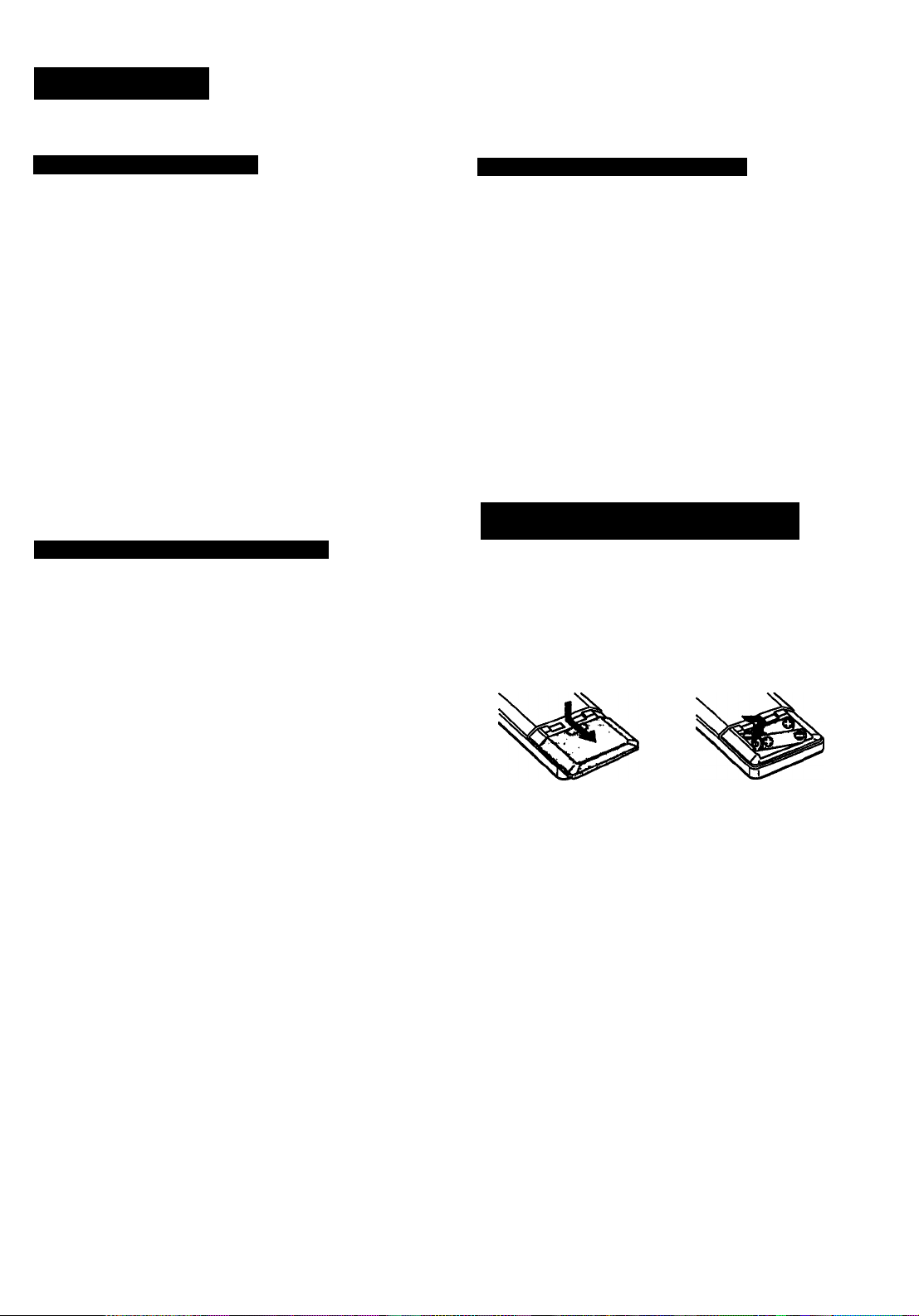
Inserting the Batteries into the Remote
Commander
Before operating remote commander, install the batteries as
shown.
2
1
Open the cover.
Insert two size AA (R6)
batteries with correct
polarity.
i
I
To avoid damage caused by battery leakage and
corrosion
When the commander will not be used for a long time,
remove the batteries.
Battery life
Normal operation can be expected about a half year using
Sony SUM-3 (NS), and a year using Sony AM-3 (NW)
alkaline batteries.
When the batteries are run down, the remote commander
will not operate the unit. In this case, replace batteries with
new ones.
Page 6
Hooking Up the System
At first, this section describes about the connection with the other equipments, the antenna
connection, speaker connection and then the AC power connection.
• Do not connect the power cord to an AC outlet nor press the POWER switch before
accomplishing all other connections.
• The cable connectors should be fully inserted into the jacks. Loose connection may cause
hum and noise.
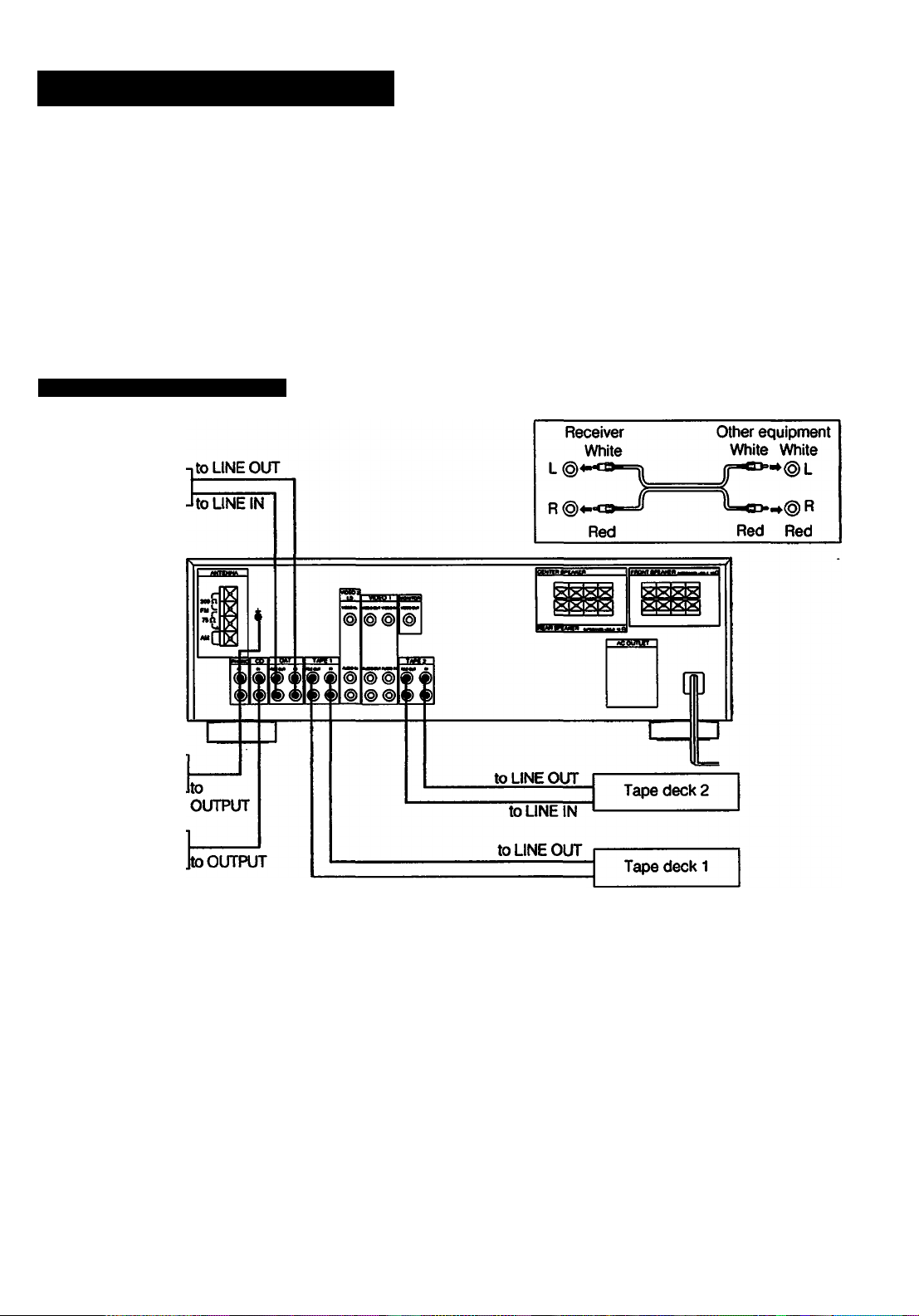
• Jacks and plugs of the connecting cord are color-coded as follows:
Red jacks and plugs: For the right channel of audio signals
White jacks and plugs: For the left channel of audio signals
Yellow jacks and plugs: For video signals
Connecting Audio Equipment
DAT deck
Record player
CD player
to LINE IN
6
Page 7
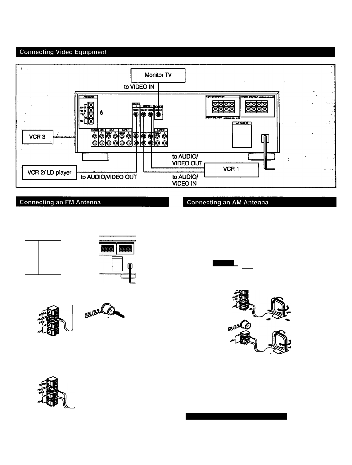
Though the ribbon antenna is supplied with this unit, the
higher quality sound will be obtained with the 75-ohm
coaxial cable.
The AM broadcast is enough received with the supplied AM
loop antenna. However, the connection of insulated wire is
also available for areas with difficult AM reception.
> 0
fl
oooboo
b
For normal use
Supplied wire antenna
For higher quality sound
75-ohm coaxial cable
(optional)
log»«
For U.K model
-'D
For UJK model
-c
Supplied wire antenna
75-ohm coaxial cable
'(optional)
0|90
0 «
For U.K model
ooloo
Supplied AM
loop antenna
Adjust the
direction.
/K,"
For areas with difficult AMI reception
In areas with troubled reception, connect a 6 to 15-meter
(20 to 50-foot) insulated wire to the AM antenna terminal.
Extend this out of doors if possible, keeping the greater
portion horizontal.
(There is no need to disconnect the supplied antenna.)
Connecting the Antenna Ground
To prevent hum. connect the ground wire to ANTENNA
ground terminal (7)7).
When an outdoor antenna is installed, be sure to connect
the ground wire for lightning protection.
Page 8
Hooking Up the System
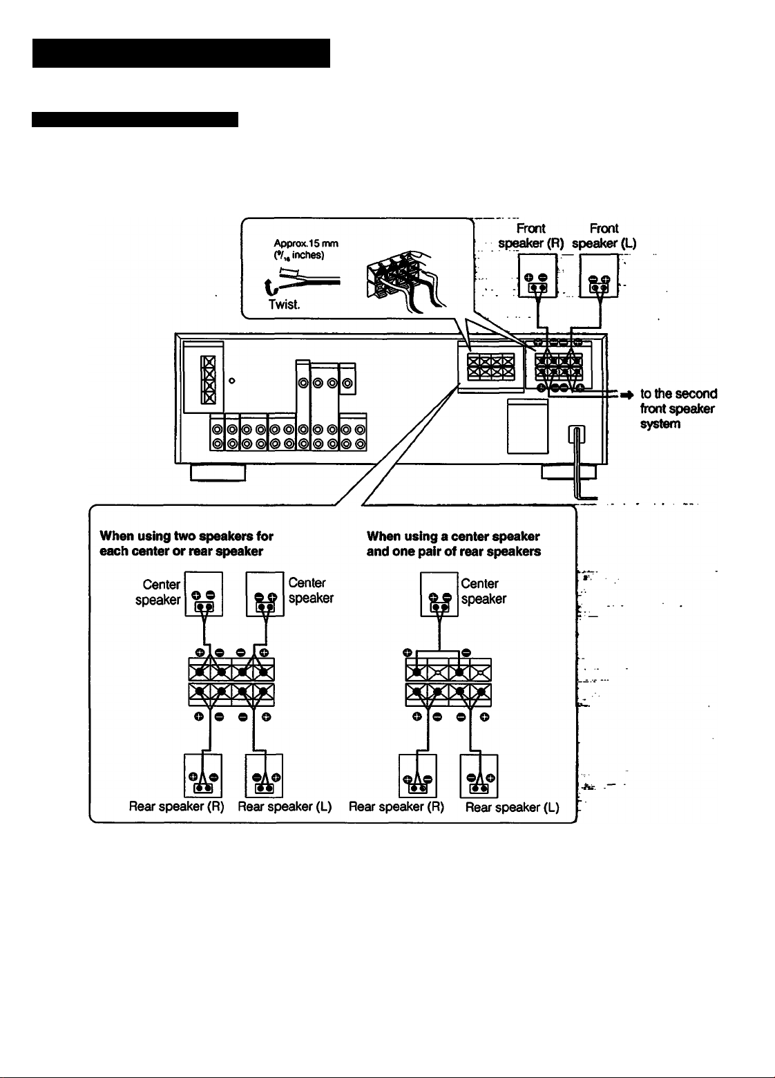
Connecting Speaker Systems
Front, rear and center speakers can be connected to this unit.
Speaker impedance and power capability
This receiver is designed to work best with speakers having
nominal impedance from 8 to 16 ohms. Be sure to use a
speaker system with adequate nominal impedance and
power handling capabilities.
When using two center speakers, use the speakers having
nominal impedance from 4 to 16 ohms.
Also, use all speakers to be connected with the equal
efficiency.
8
Note
When connecting the speaker cord to the speaker terminal,
make sure that the polarity (+ and -) of the speaker cord is
correct. If the polarity is reversed at either speaker, the
sound will be distorted and will lack bass.
Page 9
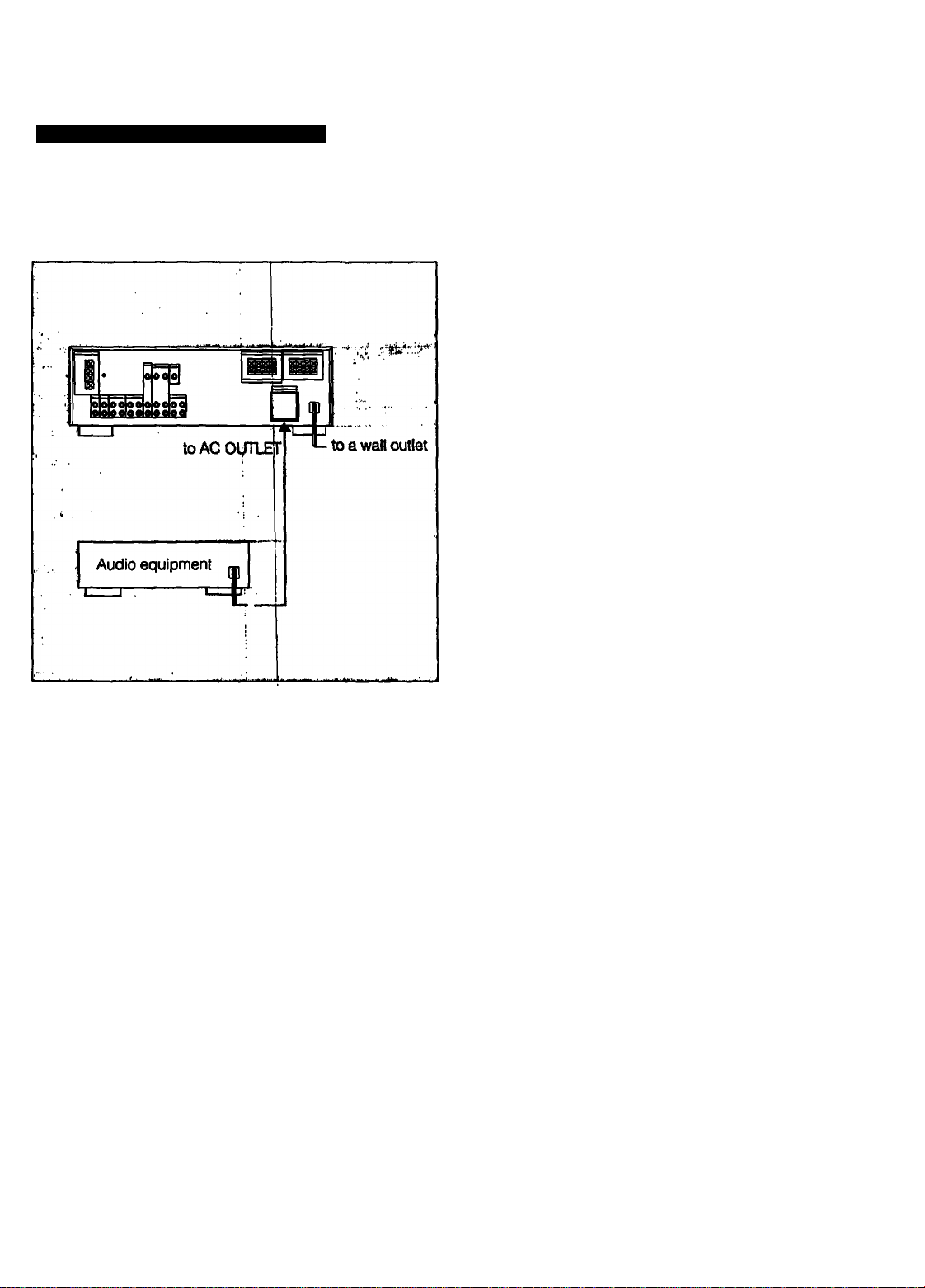
Connecting to the AC Power Outlet
Connect the AC power cord to the wall outlet last of all.
By connecting the power cord of th^ other audio equipment
to SWITCHED AC OUTLET, this unit can supply the power
source to the other audio equipmen't.
Caution
Be careful that the total power consumption of each
equipment connected to the outlets on the receiver does not
exceed 120 watts for USA and Canada models or 100 watts
for UK model.
Do not connect electrical home appliances such as an
jlectric iron. fan. TV. or other high-wattage equipment to
hese outlets.
9
Page 10
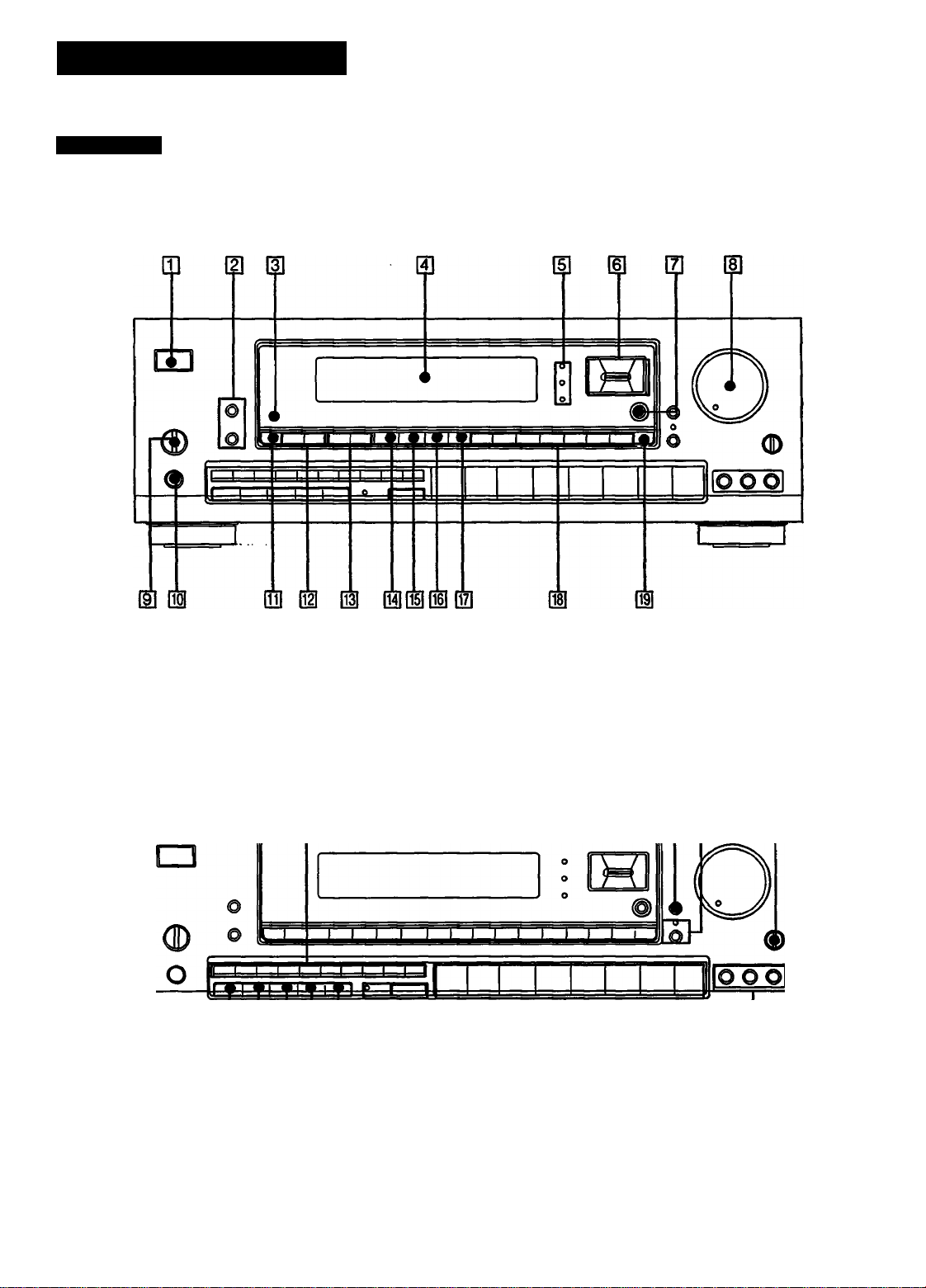
Parts Identification
Front Panel
ID ^ II il II II
ID H II
ID
10
Page 11

U] POWER switch
(The STANDBY indicator lights up when the power cord is
connected.: STR-D790 for UK model only)
m EDIT VIDEO/AUDiO buttons (See! pages 24.25.26.)
(EDIT VIDEO button: STR-D990 only)
m Remote sensor
I
m Display window
m CURSOR MODE indicators
I
[si CURSOR MODE operation buttons
(See pages 16. 21. 28. 29.31.) |
QZ l
DOLBY PRO LOGIC MODE button
(See pages 27.28.)
01 SOUND FIELD buttons
(See pages 28.29. 30.31.32.)
01 TONE ON/DEFEAT button (See page 31.)
1^ Numeric buttons (See pages 17.19. 20.21. 22.)
HH DBFB button (See page 14.)
m MUTING button and indicator (See page 14.)
|23| BALANCE control (See page 14.)
[H CURSOR MODE button (See pagp 16.21. 28. 29.31.)
d] MASTER VOLUME control (See page 14.)
[9l SPEAKERS selector (See page 14.)
QO] HEADPHONES jack
I
ini FREQ/INDEX button (See pages 18.22.)
(H] PRESET TUNING -/•<■ buttons ,
(See pages 20,22.)
m INDEX SELECT/TUNING buttons
(See pages 18.22.)
M TUNING LEVEL (See page 18.)
m UNK ON/OFF button (See page 32.)
[H SOUND HELD ON/OFF button (^e pages 28.29.)
SHIFT button (See pages 19. 20.)
|25| MEMORY button (See page 21.)
1^ DIRECT button (See page 17.)
FM MODE button (See page 17.)
|28| FM/AM button (See pages 17,18.)
M TAPE 2 MONITOR button and indicator (See page 23.)
|0| Function selectors
(VIDEO 3 button: STR-D990 only)
n] VIDEO 3 INPUT Jacks (STR-D990 only)
Page 12
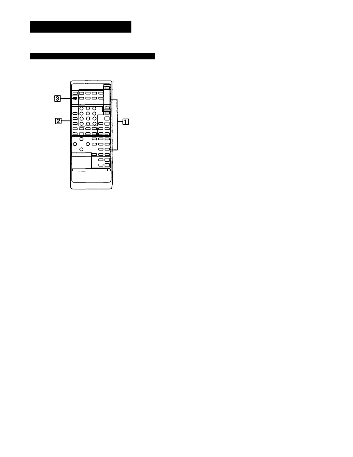
Parts Identification
Remote Commander (except for U.K. model)
QD Receiver control section
FUNCTION:
DAT. CD. TUNER. PHONO. VIDEO 1. VIDEO 2. VIDEO
3. TAPE. The each function is selected
and the each unit enters its operating mode
automatically.
SYSTEM OFF: Turns off the power of the whole system.
POWER: Turns on the power of the receiver.
SOUND FIELD buttons
U/P: This button does not function.
MODE: Selects the sound field mode.
ON/OFF: Turns on/off the sound field system.
BAND: This button does not function.
EQ: Turns on/off the setting of TONE controls.
T. (test) TONE: Generates a pink noise signal that is
sent in succession to each speaker.
CURSOR MODE: Select CURSOR MODE.
CURSOR operating buttons
REAR LEVEL +/- buttons: Control the volume of rear
speakers (surround level).
CENTER LEVEL +/- buttons; Control the volume of
center speaker (surround level).
DBFB button: Turns on/off the DBFB (Dynamic Bass
Feedback).
MUTING button: Mutes the sound.
MASTER VOL +/- buttons: Control the receiver
volume.
SLEEP: Set to the SLEEP timer mode. In this mode, the
unit is autonnatically turned off after the designated
time, (page 15)
d] other equipment control section
Numeric buttons (1 to 0): Designate the number.
ENTER: Press after designating the TV/VCR channel.
SHIFT: Select the memory page (A, B or C).
TV/VIDEO selector: Selects the program to see: TV or
VIDEO.
ANT TV/VTR button: Selects the output signal from the
antenna terminal on the VCR. either a TV signal or
VCR programs.
CH/PRESET +/- buttons: Select a preset channel.
INDEX: Set to the index tuning mode.
•«^/^: fast winding/Manual search
•: Recording
◄/►•: Play
■: Stop
II: Pause
Locates a desired selection.
REV/FWD; Press • and REV or FWD at the same time.
D (disc) SKIP: Disc skip (for a CD player equipped
with a multi-disc changer)
SELECT: Changes the settings of the FUNCTION
buttons.
d SYSTEMnrV mode switch
In TV mode (When setting the SYSTEM/TV selector
to TV.)
Only MUTING. MASTER VOL +/- and the operative
buttons in TV section on the list described on the next
page can be used.
12
Page 13

Operating with the Remote Commander
Before operating the equipments with the remote
commander, be sure to set the receiver to the desired mode
by pressing one of the FUNCTION buttons.
The FUNCTION buttons are factory set in the following list.
FUNCTION to be
pressed
DAT DAT
CD CD player |
TUNER Tuner
PHONO
VIDEO 1 Betamax VCRs
VIDEO 2 LD player |
VIDEOS
TAPE Tape deck A
Operating equipment
1
(The receiver enters the PHONO mode.)
8 mm VCRs
• When VIDEO 1,2 or 3 is pressed, the power of the
selected video equipment and W is turned on.
Operating the equipment
1 Press the desired FUNCTION.
I
2 Press ◄ (only for tape deck) or ► to start playback.
Changing the settings of the FUNCTION Buttons
List of operative buttons in SYSTEiM mode (When setting the SYSTEiM/TV seiector to SYSTEM
Operating
equipment
ENTER —
SHIR
TV/VIDEO
ANT TV/
PRESET
1
2
3
4
S
6
7
8
9
0
VTR
CH
TUNER
•
•
•
•
•
•
•
•
•
•
—
•
—
—
•
CD DAT DECK
• •
• •
• •
• •
•
• •
•
• •
— —
— — — — — —
—
— — — — — —
— —
—
— — —
A,B
•
•
•
— —
—
TV LDP
—
—
—
—
—
—
—
—
—
—
—
— —
•
• • •
• • #
•
•
• • •
•
• •
•
•
•
•
•
VTR1,
•
•
•
• •
• •
• •
—
★
—
—
2.3
#
•
•
•
★
•
•
With the SELECT button, you can replace the functions
stored in the FUNCTION buttons. ^
I
To change the settings of the FUNCTiON buttons
1 Press one of the FUNCTION buttons to be stored.
2 Press SELECT.
3 Press the 1 to 9 button to select №e desired function within
30 seconds.
4 Press ENTER.
To operate other unit temporariiy without changing the
settings of FUNCTiON
1 Press SELECT.
2 Press the 1 to 9 button to select the function.
3 Press the desired button.
After operating the unit, the receiver enters the previous
mode.
Operative buttons: POWER, N◄/►►1, ■, ◄/►, ii,
•REC, D.SKIP, TV/VIDEO, ANTTVATR. CH/PRESET
+/-, SHIFT. INDEX. '
Exampie:
To record the program source in DECK A in the CD mode
1 Press SELECT.
2 Press 3 (DECK A).
3 While pressing •, press REV or FWD.
After operating DECK A. the receiver enters the CD mode
automatically.
INDEX
D.SKIP
ex
REV or
■4 + «
FWD or
II —
■ -4
►
■
•
— — — — — —
—
—
—
—
•
— —
• •
• •
•
•
•
•
—
—
—
— —
• •
• • •
• •
•
• •
•
—
•
—
•
—
—
—
—
—
•
—
—
—
#
—
—
—
—
—
—
—
—
—
—
•
• •
•
•
—
—
• •
—
•
•
—
•
—
—
—
•
—
•
•
•: The button is operative.
—; The button is not operative.
★ : The button can operate TV and VTR connected to TV.
Note
To operate the unit correctly, the function mode of the
receiver should be same with that of the remote
commander. So, be sure to press the desired FUNCTION
button at first and then the operative button.
13
Page 14

Adjusting Basic Audio Controls
You can enjoy superb sounds using the audio adjustment
functions as shown below.
MASTER
Adjusting Volume
To adjust volume
Turn MASTER VOLUME.
To reduce the sound to a low level temporarily (- 20 dB
attenuation)
Press MUTING. The indicator lights up.
Press again to restore the same listening level as before.
Selecting the Speaker System
To drive speaker system A: Set SPEAKERS to A.
To drive speaker system B; Set SPEAKERS to B.
To drive both speaker systems A and B (series connection):
Set SPEAKERS to A+ B.
For headphone listening; Connect headphones to
HEADPHONES and set SPEAKERS to OFF.
IMPORTANT
Speaker systems A and B are series connected. When only
one speaker system is connected, no sound can be heard
at the A -I- B position.
Adjusting Left and Right Sound Balance
Adjust BALANCE to correct stereo imaging, when the
speaker position is not symmetrical.
Adjusting Tone from the Front Speakers
Press TONE ON/DEFEAT to set to ON and then press
CURSOR MODE so that TONE lights up. Press < or > to
select BASS or TREBLE respectively and then press A or v
to adjust the level.
Reinforcing the Bass
Press DBFB (Dynamic Bass Feedback) so that DBFB ON
appears on the display. Press again to turn off the effect so
that DBFB OFF appears on the display.
14
Page 15

Selecting a Program Source
To Turn Off the Power at the Desired Time
(The Sleep Timer Function)
1
Select the program eourcè.
What you aelect
Phono record
ID player
------
1-------------------------i Press
PHONO
1
This function can be operated only with the remote
commander.
This receiver has the sleep timer function. With this
function, you can turn off the power automatically at the
desired time by designating the turn-off time.
Press SLEEP on the remote commander when the power is
on. Each time SLEEP is pressed, the designating time is
displayed in the following order: 2 hours -► 1 hour and 30
minutes -* 1 hour -► 30 minutes -► SLEEP OFF.
nsgEmaanae
SLEEP
Radio Broadcast
Compact disc CD
DAT program DAT;
Taped program TAPE 1.TAPE 2
Video program VIDEb 1, VIDEO 2/LD,
When a function selector is pressed, the indicator of
the function you have selected appears on the
display.
Select the function with the remote commander, the
power switches of both this receiver and the
selected equipment are turned on.
TUNER
VIDEO 3
2 start playback of the selected program.
To change the turn-off time
1 Press SLEEP and the remaining time is displayed.
2 Press A or V to change the sleep time. The sleep time is
changed by 1 minute. It can be changed up to 5 hours
and 00 minutes (and 00 seconds).
To check the remaining time of the sieep timer
Press SLEEP. The remaining time is displayed.
15
Page 16

Selecting a Program Source
Labeling the Program Source
You can input program sources under index names you
create (up to 11 characters); for example, PHONO, TUNER,
CD etc.
1 Select the program source.
2 Press CURSOR MODE to select the INDEX mode.
If you input an already store source under any other
index name
Only the last selected index name will be valid. Each
program source can be stored under only one index name.
To switch the display mode between the original
function name display and created index name display
Each time the FREQ/INDEX is pressed, the selected function
name (which corresponds to the function selector) and the
created index name are alternately displayed.
CURSOR MODE
The INDEX indicator lights up.
------
3 Create an index name.
b
To select a letter (A to Z) or number (1 to 9).
press A or V.
To change the position, press < or >.
Repeat steps 1 to 3 for all other program sources you
want to assign an index name to.
16
Page 17

Receiving Broadcasts
Tuning in a Station Directly (Direct Tuning)
1 Press TUNER.
TUNER frequency appears on the display.
Select FM or AM.
To correct the entered frequency
Repeat steps 3 to 4.
For entering AM frequencies
You need not enter the last ”0". (except for U.K. model)
However, if you have changed the AM tuning interval to 9
kHz, enter all the digits.
if you enter a frequency not covered by the tuning
interval
The entered value is automatically rounded up or down to
the closest value covered by the tuning interval.
Tuning intervals for direct tuning are the followings;
FM: 50 kHz interval
AM: 10 kHz interval (changeable to the 9 kHz interval)
(See page 5)
9 kHz interval (only for STR-D790 U.K. model)
When the entered frequency does not exist in the
receivable frequency range
The entered digits (up to 5 digits for FM or up to 3 digits for
AM) blink in the frequency display area, and reception does
not take place.
If this occurs, press DIRECT again, and enter the correct
frequency. The frequency range of the receiver is 87.50 to
108.0 MHz for FM, and 530 to 1710 kHz or 531 to 1602 kHz
(only for STR-D790 U.K. model) for AM.
When an FM stereo program is noisy
When the unit receives an FM stereo program, the STEREO
indicator lights in the display window. If the stereo program
is noisy, press FM MODE to change the mode over the
MONO. This eliminates the stereo effect, but the noise will
be greatly reduced.
To return to the stereo mode, press FM MODE again.
Press DIRECT.
4 Enter the frequency.
rr~T2 13 1» Is
....... . .16 ,
b
The entered frequency is displayed.
Example 1: FM 102.50 MHz .Example 2: AM 1350 kHz
FM
/0?.50
I9SD
k№
Page 18

Receiving Broadcasts
Scanning Stations Automatically (Auto Tuning)
When you do not know the frequency of the station to be
received, proceed as follows.
If the automatic scan stops frequently (for FM reception only)
You can receive only the strong stations by pressing
TUNING LEVEL. HIGH appears on the display.
To receive all receivable stations again
Press TUNING LEVEL so that HIGH goes off.
18
Page 19

Presetting Stations (Station Preset)
A total of 30 FM/AM stations can beimemorized in any
desired sequence.
1
While MEMORY appears, press the desired
number.
I» I'
6
b
Repeat above steps for presetting other desired
stations.
Replacing a preset station
Preset another station on the number of the station to be
replaced. The previously preset station will be erased.
TUNER frequency appears on the display.
Tune in the desired station:
(See "Auto Tuning" or "DirjBCt Tuning".)
Press MEMORY.
15
MEMORY appears on the display.
4 Whiie MEMORY appears, ^iect the memory page
(A,BorC).
Each time SHIFT is pressed, A, B or C is indicated
cyclically.
J
Page 20

Receiving Broadcasts
Tuning in a Preset Station (Preset Tuning)
There are two ways to perform the preset tuning.
In method A, the direct tuning, select by designating the
desired preset station number directly with the numeric
button. In method B, the scan tuning, select the preset
station with the PRESET TUNING -/+ button.
Method A: Direct tuning
Method B: Scan tuning
Press TUNER.
1
Press TUNER.
TUNER frequency appears on the display.
Select the memory page (A, B, or C).
Each time SHIFT is pressed, A,B or C is indicated
cyclicallly.
3 Designate the desired preset station number with
the numeric button.
M. . |2 13 14 IS |6
TUNER frequency appears on the display.
2 Select the desired preset station with PRESET
TUNING -or+.
PRESET TUNING
* ^
\
For a lower
preset number
A1 AO
+
I ^ r.n'*
IMPORTANT
The memorized station is mainteuned for approximately one
month even if the power cord is disconnected from the AC
power outlet. If they are erased, store the stations again.
For a higher
preset number
B1 BO
^ ^ I4
r^i^ ^ I
Page 21

Labeling the Preset Stations (Station Index)
You can divide preset stations under index names you
create (up to 5 characters). If yoiii want to categorize the
preset stations by kinds of music; for example, create
indexes such as ROCK, JAZZ, etc.
laMMÉeaBKWMatiwiB«
1
Press TUNER.
Repeat steps 2 through 4 for aii other stations
you want to assign an index name.
if you store an aiready categorized station under any
other index name
Only the last selected category will be valid. Each station
can be stored under only one index name.
To display the frequency and index name of preset
stations
Each time DISPLAY FREQ/INDEX is pressed, frequency and
index name of the preset station are alternately displayed.
TUNER I
O
TUNER frequency appears on the display.
Tune in the desired station with Preset Tuning.
3 Press CURSOR iNODE to seiect the iNDEX mode.
CURSOR MODE
The INDEX indicator lights up.
Create an index name.
------
:
To select a letter (A to Z) pr number (1 to 4),
press A or V. :
To change the position, press < or >.
Page 22

Receiving Broadcasts
Selecting a Station among the Preset Stations in
the Index (Index Tuning)
POWER -► ON
1
_ _ _ _ _ _ _ _
o 1
I;IH)
e
,o
0 <]D
1-1 -LI. 1 Ij
'
- - - -
"^1
2 3
Press TUNER.
TUNER
‘
15
TUNER frequency appears on the display.
Receiving FM Simulcast TV Programs
MONITOR
VIDEO OUT
Select VIDEO 1, VIDEO 2/LD or VIDEO 3 (STR-
D990 only).
VIDEO 1. VIDEO 2/LD or VIDEO 3 appears on the
display.
According to video inputs connected to an
equipment to which the VHF antenna is connected.
Press FREQ/INDEX to set to the INDEX mode.
When no index name is memorized, "no-index"
appears on the display.
Select the desired station.
• To select a station in the same index:
PRESET TUNING
For lower channel
index station
• To select a index station other than the displayed
index station:
INOEWSELECT TUNING
b
31
For higher channel
index station
PRESET TUNING
31
For lower For higher
channel channel index
index station station
Turn on the monitor TV.
Select the desired program on the TV tuner or the VCR.
Select TUNER and tune in the FM simulcast TV program on the receiver.
TUNER
15
b
!2
Page 23

Recording an Audio Source
Recording onto an Audio Tape Deck or DAT Deck Tape Dubbing
Audio signals
1
Select the desired program source with the
function selector. |
For an FM/AM broadcast, tune in the desired station.
2 Set the tape (DAT) deck in the recording mode.
Audio signals
1,4
1 Insert the recorded tape into tape deck 1 (or the
OAT deck).
2 Insert a blank tape into tape deck 2 and adjust the
recording level.
3 Start playback of the selected program source.
Note on recording
For TAPE 1,2 and DAT REC OUT jacks, the settings of
SOUND FIELD and DBFS do not hpve any effect on
recording.
Monitoring the recorded sound
If you have connected a 3-head tape deck to the TAPE 2
jacks, you can monitor the recording results. While
recording or dubbing, press TAPE 2 MONITOR so that the
TAPE 2 MONITOR indicator lights yp. To listen to the
source sound again, press the button again so that the
indicator goes off.
3 Press TAPE 1 or DAT to select the deck for
playback.
4 Start the playback of the tape (or the DAT) in tape
deck 1 (or the DAT deck), and set tape deck 2 in
the recording mode.
Dubbing will start.
Note on tape dubbing
Tape dubbing is possible only in the following directions:
From
(Playback deck)
Tape deck
connected to
TAPE 11N
DAT deck
connected to
DAT IN
Press the function selector according to the playback deck.
Tape deck connected to TAPE 2 OUT
DAT deck connected to DAT OUT
Tape deck connected to TAPE 1 or 2
OUT
To
(Recording deck)
23
Page 24

Editing a Video Source
Video Tape Dubbing
If the AUDIO indicator is lit in the display window, press the
EDIT AUDIO button to make the indicator go out.
With the STR-D990
Video signals
POWER
3 TV tuner/VCR 2
to VIDEO 2
VIDEO IN/
4
AUDIO IN
VCR11 4
to VIDEO 1 VIDEO
OUT/AUDIO OUT
to VIDEOS
VIDEO IN/
AUDIO IN
TV tuner/VCR3 3
To listen to an audio program during video tape dubbing
1 Press the appropriate function selector.
2 Start the selected audio program source.
With the STR-D790
Video signals
POWER -» ON]
2 TVtuner/VCR2
to VIDEO 2 t
VIDEO IN/
AUDIO IN
I VCR 11 3
to VIDEO 1 VIDEO
OUT/AUDIO OUT
Select the playback VCR with EDIT VIDEO.
To select VCR 2. press EDIT VIDEO so that ‘2> 1*
appears on the display.
To select VCR 3. press EDIT VIDEO so that '3> V
appears on the display.
2 Press VIDEO 2/LD or VIDEOS to select the video
signal to monitor on the monitor TV according to
the VCR to be played.
VIDEO 2/LD; for the VCR 2
VIDEOS: for the VCR 3
Set the playback VCR to the playback mode.
4 Set the VCR 1 to the recording mode.
Dubbing will start.
— Video editing —
To switch the playback VCR during dubbing
Press EDIT VIDEO. Each time you press the button, the
playback VCR switches from the VCR 2 to the VCR 3 (or the
VCRS to the VCR 2).
To view the other video source(s) on the monitor TV
during dubbing
Press the appropriate function selector, VIDEO 1, VIDEO 2/
LD, or VIDEOS.
1
Press VIDEO 2/LD.
2 Set VCR 2 to the playback mode.
3 Set the VCR 1 to the recording mode.
Dubbing will start.
To listen to an audio program during video tape dubbing
1 Press the appropriate function selector.
2 Start the selected audio program source.
To record a TV program
You can record a TV program on VIDEO 1.
24
Page 25

Adding New Sound on a Video Tape during Video
Editing
During video tape editing, you cari add the desired sound
on the recording VCR from various audio program sources.
With the STR-D990
Select the audio program source with the
function selectors.
6 Releasethepausemodeof the playback VCR
and set the VCR 1 to the recording mode.
' ^ Videosignals
POWER -»• OnI
VC^2, 3, 6
Audio signals
VCR1 6
to VIDEO 1
irt
VIDEO OUT/
AUDIO OUT
1 Select the playback VCR with EDIT VIDEO.
To select VCR 2, press EDIT VIDEO so that "2> 1*
appears on the display.
To select VCR 3, press EDIT VIDEO so that “3> 1"
appears on the display.
7 Start playback of the selected audio program
source.
Video dubbing starts and the audio program source
is also recorded on the VCR 1 simultaneously.
Set the playback VCR to the playback mode.
3 At the point where audio cjubblng starts, press
the pause button on the playback VCR.
Press EDIT AUDIO.
AUDIO appears on the display.
25
Page 26

Editing a Video Source
Adding New Sound on a Video Tape during Video
Editing
With the STR-D790
Video signals
6 Release the pause mode of VCR 2 and set VCR 1
to the recording mode.
7 Start playback of the selected audio program
source.
Audio dubbing will start.
r ...
Press VIDEO 2/LD.
2 Insert a recorded video tape into VCR 2 and set
the VCR to the playback mode.
3 At the point where audio dubbing starts, press
the pause button on VCR 2.
4 Press EDIT AUDIO.
AUDIO appears on the display.
Select the audio program source with the
function selectors.
26
Page 27

Chapter 3 Advanced Operaltiona
Getting Ready for Dolby Surround Sound
This section describes about selecting the speaker
configuration and then adjusting the speaker volume and
the delay time of the rear speakers so that you can enjoy
the Dolby surround sound.
Placement of Speakers and Selecting the PRO
LOGIC MODE
The Dolby Pro Logic Surround D^oder has the same
functions for playback, such as rnovie theaters and gives a
theater-like experience in your listening room, naturally
reproducing the audio sound field.
The STR-D990/D790 incorporates a decoder which
reproduces the specially encodé surround sound of Dolby
surround video programs. ,
In the Dolby surround mode, select the speaker operation
mode according to your speaker'configuration by pressing
the DOLBY PRO LOGIC MODE button. Each time the
DOLBY PRO LOGIC MODE button is pressed, the DOLBY
PRO LOGIC MODE is changed in the following order:
NORMAL -► WIDE 3 CH. LOGIC -*> PHANTOM
PHANTOM mode
Select this mode when you play back a Dolby surround
program source without using a center speaker. The sound
of the center channel is output from the front (L and R)
speakers.
Select this mode if you use a medium to big center speaker
Center speaker
Front speaker (L)
:er (L) \ Front s speaker (R)
NORMAL mode
Select this mode if you use a small center speaker. The
bass sound of the center channel jis output from the front
speakers, as a small speaker cannot produce enough
bass.
Rear speaker (L) Rear speaker (R)
3CH. (Channel) LOGIC mode Select this mode when you play back a Dolby surround
program source only with the front and center speakers.
The sound of the rear channel is output from the front (L anc
R) speakers.
Even for video software which does not carry the
Some commercially available software may have Dolby
surround processed sound tracks even though It is not so
indicated on the package.
Page 28

Getting Ready for Dolby Surround Sound
Adjusting the Speaker Volume
6 Press CURSOR MODE.
'o enjoy the surround sound to the maximum on playing any
>rogram sources, adjust the front, rear, and center (if
;onnected) speakers to the same volume level. The
idjustment must be done with a test tone in the DOLBY
>URROUND mode, but the level once adjusted can be used
3r all surround modes.
'ou can adjust the volume level from your listening position
>y using the remote commander.
i POWER-»onI 14 2 6
•°.l I—t-
d) o t W I T IÌÉM-I
o (D
The SURR (surround) indicator lights up.
To adjust the level of rear speakers
Press A or V to select the rear level nrode and then
adjust the level with < or > or REAR LEVEL +/- on
the remote commander.
To adjust the level of center speakers
Press A or V to select the center level mode and
then adjust the level with < or > or CENTER LEVEL
+/- on the remote commander so that sound from
each speaker is heard in the same volume level at
the listening position. (When adjusting the VOLUME
control on the receiver, all speakers are adjusted
simultaneously.)
ooioe
O ' OBOO
O
i-5,7
30
aO
1 Press SOUND nELOONfOFF to ON.
The last selected sound field is displayed in box.
2 Press DOLBY SUR.
DOLBY SUR appears on the display.
Select a program source with the function selector and start playback.
4 Select the Dolby pro logic mode with the DOLBY
PRO LOGIC MODE button according to your
speaker system.
Sequence of the test tone
In a system with a center speaker;
The test tone will be output automatically from the front L,
center, front R, and the rear speakers in succession.
Front left
V Center !
Front right
ksJ ^ H ^ fez
|3CH. LOGIC;
NORMAL and WIDE modes
Rear left and right
0
In a system without a center speaker:
The test tone will be output automatically from the front left
and right speakers and the rear speakers alternately.
©
Press T. TONE on the remote commander to set toon.
8
The receiver is preset in the factory to get an optimum
surround level as long as each speaker has an equal
efficiency.
Page 29

Adjusting the Surround Sound
Adjusting the DeJay Time of the Rear Speakers
—for Dolby surround mode
The delay time is a time between the surround sound from
the front and that from rear speakers. The delay time is
adjustable from 15 ms to 30 ms. (For other surround mode,
the adjustable delay time is from 5 to 30 ms.)
TTT
1 Press SOUND RELDON/OFF to ON.
The last selected sound field is displayed in box.
Press DOLBY SUR.
DOLBY SUR appears on the display.
Press CURSOR MODE.
The SURR (sumound) indicator lights up.
4 Press A or V to select the delay time mode and
adjust the delay time with ^ or >.
To turn off the surround effect
Press SOUND FIELD to OFF.
The normal sound without surround effect will resume.
Both level and delay time of the surround is memorized
each time after adjusting with the cbrsor operation buttons.
They will be restored when the surround mode is resumed.
Note
The delay time for the rear speakers can be adjusted even
in the 3 CH. LOGIC mode.
I
Page 30

Sound Field Settings
Available Type of Effects
7 recommended sound field programs (combination of the settings of the surround and tone control.) have been preset in the
factory. Since these programs are appropriate for the most type of music and listening situations, you can enjoy the sound
effect by selecting the desired sound field program according to the program source. And you can also manipulate various
parameters to finely tune the factory-preset settings to your room, or create original sound effects as you like.
^field
Parameter ^
Tone
•a
¡1
3 o
(0 «
DOLBY SUR: Decodes programs processed with the Dolby
THEATER: Adds the reflection of a theater to decoded
LIVE: Reproduces the acoustics of a large concert hall. It is
HALL: Reproduces the acoustics of a rectangular concert
DISCO: Boosts high and low frequencies and the dynamic
Delay time
Rear level
Center level
surround.
signals of the Dolby prologic decoder.
effective for playing a program source with hard sound.
hall with soft sound. It is effective for playing a program
source with hard sound.
sounds are reproduced.
DOLBY SUR THEATER UVE HALL
• •
•
•
• •
• •
• • •
DISCO
• • • •
• •
• •
SIMULATED
ACOUSTIC
•
•
SIMULATED: Gives a simulated stereo effect to monaural
i sound.
ACOUSTIC: The surround effect is defeated and only the
tone control is available.
30
Page 31

Adjusting the Tone Controls
Adjusting the Sound Field Programs
imwiiiin
2 1
I
•ttt;
1 Press the desired SOUND FIELD program.
Press CURSOR MODE so that TONE lights up.
3 Press <1 or > to select BASS or TREBLE.
4 Press A or V to adjust the level.
To defeat the TONE effect
Press TONE ON/DEFEAT to DEFEAT.
In the TONE DEFEAT mode, tone control cannot be
adjusted.
1 Press the desired SOUND FIELD program.
When DOLBY SUR or THEATER Is selected on
step 1, press DOLBY PRO LOGIC MODE to select
the PRO LOGIC MODE.
Press CURSOR MODE so that SURR lights up.
4 Press Aorvto select the mode you want to
adjust.
S Press <1 or > to adjust the level or delay time.
After setting the surround program, the setting is
stored automatically.
When you store a new SOUND FIELD effect
The previous SOUND FIELD effect is erased and the new
one will be replaced.
Even If AC power cord is disconnected
The stored data is maintained for approximately 1 month.
When selecting ACOUSTIC
ACOUSTIC does not have the surround effect and only the
effect of TONE controls can be available. So when selectin;
ACOUSTIC, only the setting of the TONE controls can be
adjusted.
3i
Page 32

Sound Field Settings
Linking the Sound Field Memory to Preset
Stations or Program Source
1
Tune in a station or select the program source to
be linked with sound fieid data.
Press LINK ON/OFF to ON.
Press the desired SOUND FIELD program.
Notes
• When other sound field is selected in the LINK ON mode,
the previous sound field setting linked with the preset
station or program source is replaced with the newly
selected one. Therefore, if you want to select other sound
field without changing the sound field setting in memory,
press LINK ON/ OFF to OFF and then select other sound
field.
• When the sound field setting is adjusted, the sound field
setting linked with the preset station or program source is
also changed.
Page 33

Troubleshooting Guide
Before proceeding through the ch^k list below, examine
the connections and the procedures outlined in the manuai.
Should any problem persist after you have checked the
following items, consult your nearejst Sony dealer.
Problem j
No FM station can be located by !
Auto-Tuning operation.
1
The STEREO indicator flickers or does
not appear when receiving stereo ‘
programs.
No station can be tuned in by Auto-
Tuning operation.
1
No stations can be tuned in by
pressing PRESET TUNING +/-.
No sound is heard even if you adjust
VOLUME.
Cause
The signal strength of the stations is
too weak.
A very weak FM station or a noisy FM
program is received.
The AM tuning interval is set
incorrectly.
The signal strength cf the station is too
weak for Auto-Tuning.
No stations have been preset. Preset the stations. (See page 19)
The speaker or program source
equipment is not connected correctly.
Press TUNING LEVEL to set the
receiving signal level low.
Check the antenna connection.
Adjust the antenna or connect an
external FM antenna.
Press FM MODE to set to MONO
mode.
Change the tuning interval according
to the AM frequency allocation system
of your country. (See page 5)
Adjust the antenna.
Directly tune in the stations.
(See page 17)
Connect the equipment correctly.
Solution
!
'
No sound or sound at very low level is
heard from rear speakers.
i
Sound is heard only at a very low
volume. '
One channel does not transmit audio,
or the volume from the left and right
speakers is unbalanced. |
i
The SPEAKERS selector is not set
correctly.
TAPE 2 has been pressed for a
program source other than tape deck
2. (The indicator is lit.)
A wrong function selector has been
pressed.
The function switch on the VCR is not
set correctly.
SOUND FIELD function is turned off. Press SOUND FIELD ON/OFF to turn
Monaural program source is played
back in Dolby surround mode.
MUTING has been pressed. (The
MUTING indicator is lit.)
The BALANCE control is not set
appropriately.
The speaker or program source is not
connected correctly.
Set the selector correctly.
Press the button to disengage.
Press the correct function selector.
Check and set it correctly.
on the function.
Select the other modes.
Press the button to disengage.
Adjust the BALANCE control.
Check and properly connect the
equipment
3;
Page 34

Troubleshooting Guide
Problem
There is an abrupt loss of sound from
one or both of the speakers, and the
PROTECTOR indicator flickers in the
display window.
Sound transmitted from the speakers
is reversed.
There is lack of bass sound or the
instrument position is obscure.
Severe hum or noise is heard.
Cause
A short-circuit problem activates the
protective circuit.
The speakers are not connected
correctly.
The ©/© connection of the speaker
is reversed.
The connecting cords are not shielded
type.
A transformer, motor. TV or fluorescent
light affects the connecting cords.
The audio components are too close
to a TV set.
The unit is not grounded. Connect the ground wire to the
Turn off the unit, eliminate the shortcircuit problem and turn on the power
again. If there is no short-circuit
problem, consult your nearest Sony
dealer.
Connect the right speaker to the R
SPEAKER terminals and the left
speaker to the L SPEAKER terminals.
Connect the speaker with the correct
phase.
Use shielded type cords.
Place the connecting cords in a
location away from a transformer or
motor, and at least 3 meters (10 feet)
from a TV set or a fluorescent light.
If both are used at the same time,
separate the TV from the audio
components.
antenna ground tenninal.
Solution
The connections are loose. Make secure connections.
The plugs and jacks are dirty. Wipe the plugs and jacks with a cloth
Surround effect cannot be obtained. The unit is in a wrong mode.
The SOUND FIELD circuit is turned
off.
The remote commander will not
operate.
The equipment cannot be operated.
The batteries are exhausted.
The commander head is not pointed
toward the unit's front.
The mode of the receiver is not same
with that of the remote commander.
lightly dampened with alcohol.
Press CURSOR MODE to set the
surround mode.
Press SOUND FIELD ON/OFF.
Replace the batteries with new ones.
Point the commander head toward the
receiver.
Press the desired FUNCTION button
again.
34
Page 35

Specifications
Audio Power Specifications
POWER OUTPUT AND TOTAL HARMONIC
DISTORTION I
I
Stereo mode
With 8-ohm load, both channiels driven,
from 20 - 20,000 Hz, rated 100 watts (STRD990) or 80 watts (STR-D790) per channel
minimum RMS power, with np more than
0.1 % total harmonic distortion from 250
miiliwatts to rated output. !
j
Surround mode
STR-D990 SjTR-D790
FRONT
CENTER
REAR
65W + 65W 80W + 80W
65W 26 W
25 W
20 W
other Specifications
Dynamic power output
Harmonic distortion at rated
output
Intermodulation (IM) distortion at
rated output
Frequency
response
Residual noise
banping factor
(8 ohms, at 1kHz)
Input sensitivity/
Impedance
PHONO RIAA equalization curve ±0.5
CD. DAT.
TAPE 1,2
VIDEO 1.2.3*
PHONO MM
DAT.CD,
VIDEO 1.2,3*
TAPE 1.2
QTP.nQOn-
140W+'l40W(8ohms)
190 W + 190 W (4 ohms)
STR-D790:
105 W+ 105 W (8 ohms)
140 W + 140 W (4 ohms)
Less than 0.1 %
Less than 0.1 %
dB
10 Hz —70kHz!®dB
Less than 70jiV
50
2.5 mV, 50 kilohms
200 mV
50 kilohms
S/N PHONO MM
DAT. CD
VIDEO 1.2.3*
TAPE 1.2
Output DAT OUT.
MUTING
OBFB
TONE
TAPE OUT 1.2
VIDEO 1
SPEAKERS Accepts speakers of 8-16 ohms
HEADPHONES Accepts headphones of high
-20dB
+ lOdBatTOHz
± 10 dB at 100 Hz and 10 kHz
87 dB
79 dB” (A,2.5mV)
105 dB
85 dB** (A, 200 mV)
200 mV
10 kilohms
and low impedance
* STR-D990 only
•• 78IHF
35
Page 36

Specifications
FM tuner section
Frequency range 87.5—108.0 MHz
Antenna terminals 300 ohms, balanced
Sensitivity at 50 dB 18.3 dBf, 4.5 jiV (mono)
Usable sensitivity 11.2dBf,2pV(IHF)
S/N
Harmonic
distortion at
1 kHz
IM distortion Mono
Separation
Requency response
Selectivity
Capture ratio
Mono
Stereo 74 dB
Mono
Stereo
Stereo
75 ohms, unbalanced
38.3 dBf, 45 pV (stereo)
80 dB
0.3%
0.5%
0.3%
0.5%
45 dB at 1 kHz
30Hz—15kHzIjdB
60 dB at 400 kHz
1.2 dB
Video section
-
Inputs
Outputs
STR-D990 STR-D790
VIDEO 1,2,3;
1 Vp-p 75 ohms
VIDEO 1, MONITOR: 1 Vp-p 75 Ohms
General
------------^
Tuner section
System
Reamplifier
section
Power amplifier
section
Power requirements
Power consumption USA model:
STR-D990 STR-D790
____
PLL quartz-locked digital synthesizer
system
Low-noise NF type equalizer
Pure-complimentary SEPP
120VAC,60Hz
U.K. model; 240 VAC, 50/60 Hz
240 W
Canada model;
320 VA
VIDEO 1,2:
1 Vp-p 75 Ohms
USA model:
200W
Canada model ;
270 VA
AM suppression ratio 54 dB
Image response ratio 70 dB
IF response ratio 70 dB
Spurious response ratio 80 dB
RF intermodulation
at 800 kHz
Auto tuning
threshold
Low
High 50 dBf
60 dB
30 dBf
AM tuner section
Frequency range
Antenna
Usable sensitivity 50 dB/m (at 1,000 kHz or 999 kHz)
S/N 54dB(at50mV/m)
Harmonic distortion
530 —1710 kHz (with 10 kHz interval)
531 —1710 kHz (with 9 kHz interval)
531 —1602 kHz (only for STR-D790 U.K.
model)
Loop antenna
0.5%(50mV/m,400Hz)
AC outlets USA and Canada models:
Dimensions
Weight
Supplied accessories FM ribbon antenna (1)
Design and specifications are subject to change without notice.
Note
This appliance conforms with EEC Directive 87/308/EEC regarding
interference suppression.
Two switched, total 120 watts
U.K. model:
One switched, 100 watts max.
430 X 147.5 X 350 mm
(17 X 5 V, X 13 % inches)
10.5 kg
(23lb2oz)
AM loop antenna (1)
Remote commander (1)
Sony Batteries SUM-3(NS) (2)
10.3 kg
(22lb11oz)
Selectivity 35 dB (9 kHz), 40 dB (10 kHz)
Auto tuning threshold
55 dB/m
36
Page 37

Quick Reference
When operate the unit consulting this Quick Reference, make sure that the unit and
the various audio/video equipment are properly connected.
Ex. Tuning in the FM station of 102.50 MHz
DirBctly tuning in an
FM or AM elation
Praaetting ataUona
Tune in a
• desired ■
staiton
ariWiii
15
Select
memory
page
lO^.SO
•*»
l_Lr,__J~
FIs’
Select
channel No.
37
Page 38

Quick Reference
£<H)
POWER
Labeling the preset
stations
I POWER I
Tune in a
desired station
with the preset
tuning.
INDEX
-o:-
CURSORMOOE —
Create an index name
BG
b fe
INDEX SELECT/TUNIN6
Selecting a station
among the preset
stahons in the index
o
Seiect the station memorized
under the same index name.
PRESET TUNING
-n-V
...........
I
b
b
J
38
Page 39

AdQusting the TONE
controls
1
Select the , "'P,'
desired ' ^
SOUND FIELD' cursor mode - O
program. i It
1
TONE
— ^
3 b
Select BASS or
TREBLE.
LEVEL
Q
Ad|usting the
surround setting
Calling up the SOUND
FIEiJ) netting
LinMng the SOUND
FIELD memory to
preset stations
Select the "P'
desired ^ ^
SOUND field! cursor mode- O
program. | J hr
Press thb desired
SOUND FIELD program.
b
Tune in a station or select
the program source to be
linked with sound field
data.
^ V / ^
^ $
3 15
UNK
Select the
mode.
LEVEL
— BQ
b
Select the desired
SOUND FIELD program.
l~l->l - I -
b
Page 40

Quick Reference
Remote Commander Operations
To change the
Bettings of FUNCTION
To operate other unit
temporarily without
changing the settings
of FUNCTION
FUKCnOWBYSTEMOW
ran ran naa @
ffst ISS3 gia
b
SELECT
Press the number (1 to 9).
- 'S ~
ccp OMT oecKA
© © ©
OBCKB TV UP
Q S *2
© © ©
O © Q
b
SS.ECT
SfTBI
o © ©
oecKt IV UP
O © ©
vmt vim vfro
© © ©
enoi
O © O
b
Press the number (1 to 9).
Press the desired button
to operate other unit.
ENTER
■ %
Sony Corporation Printed in Malaysia
 Loading...