

Sony STRD-760-Z Service manual
STR-D760Z/DE815G
SERVICE MANUAL
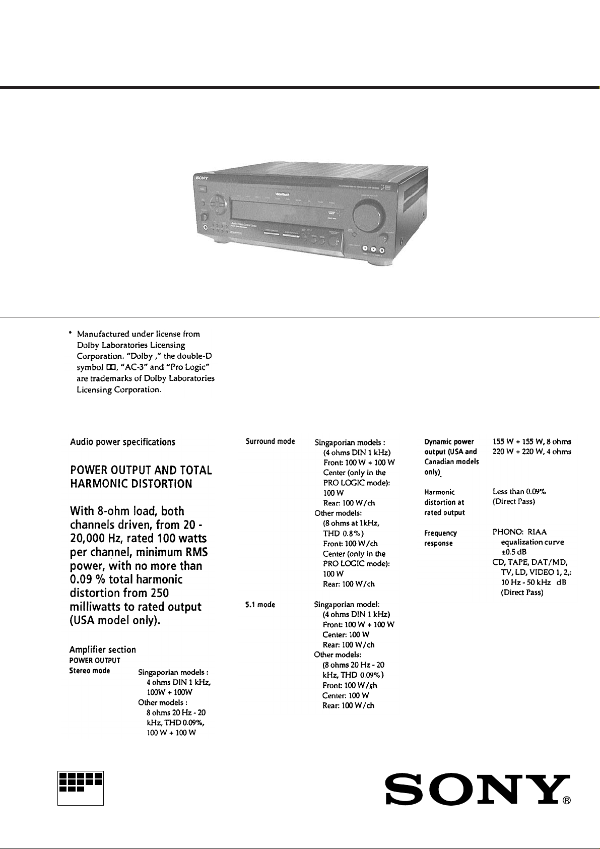
Photo : STR-DE815G
US Model
STR-D760Z/DE815G
Canadian Model
E Model
Australian Model
PX Model
STR-DE815G
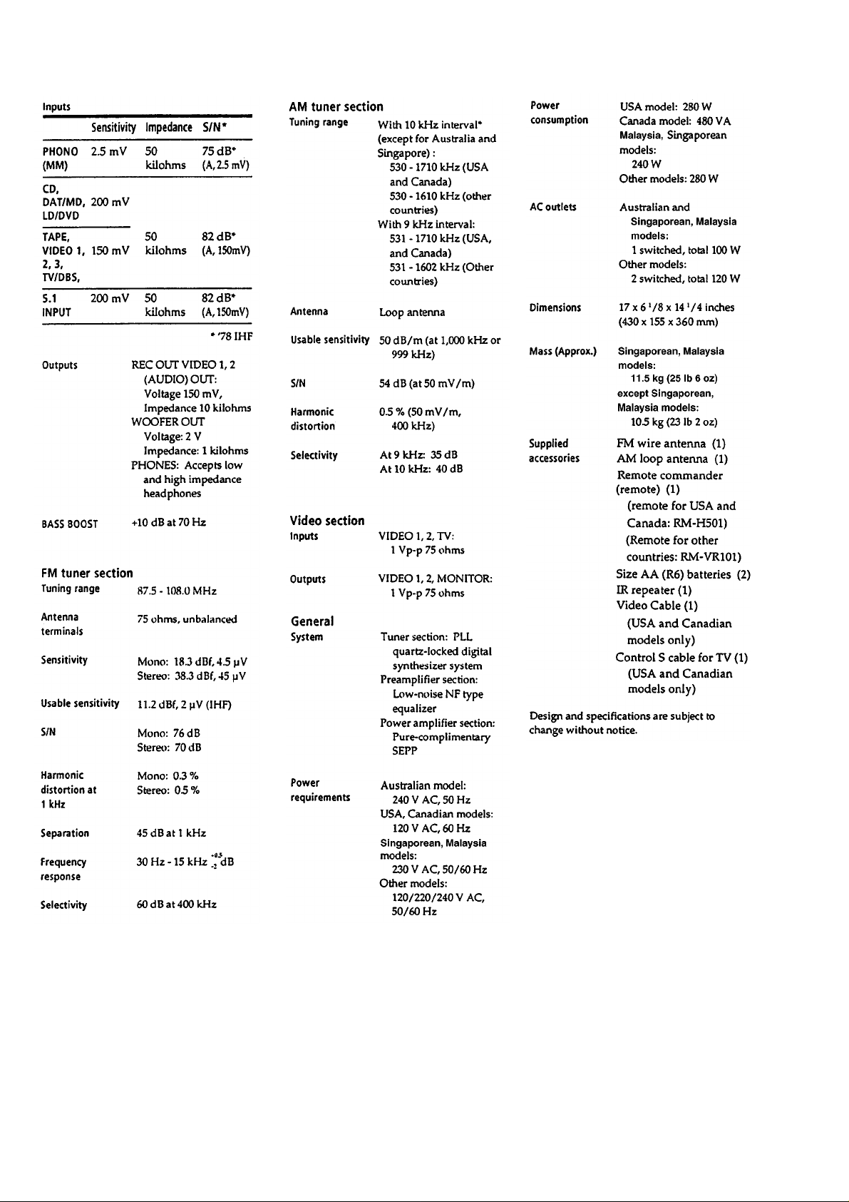
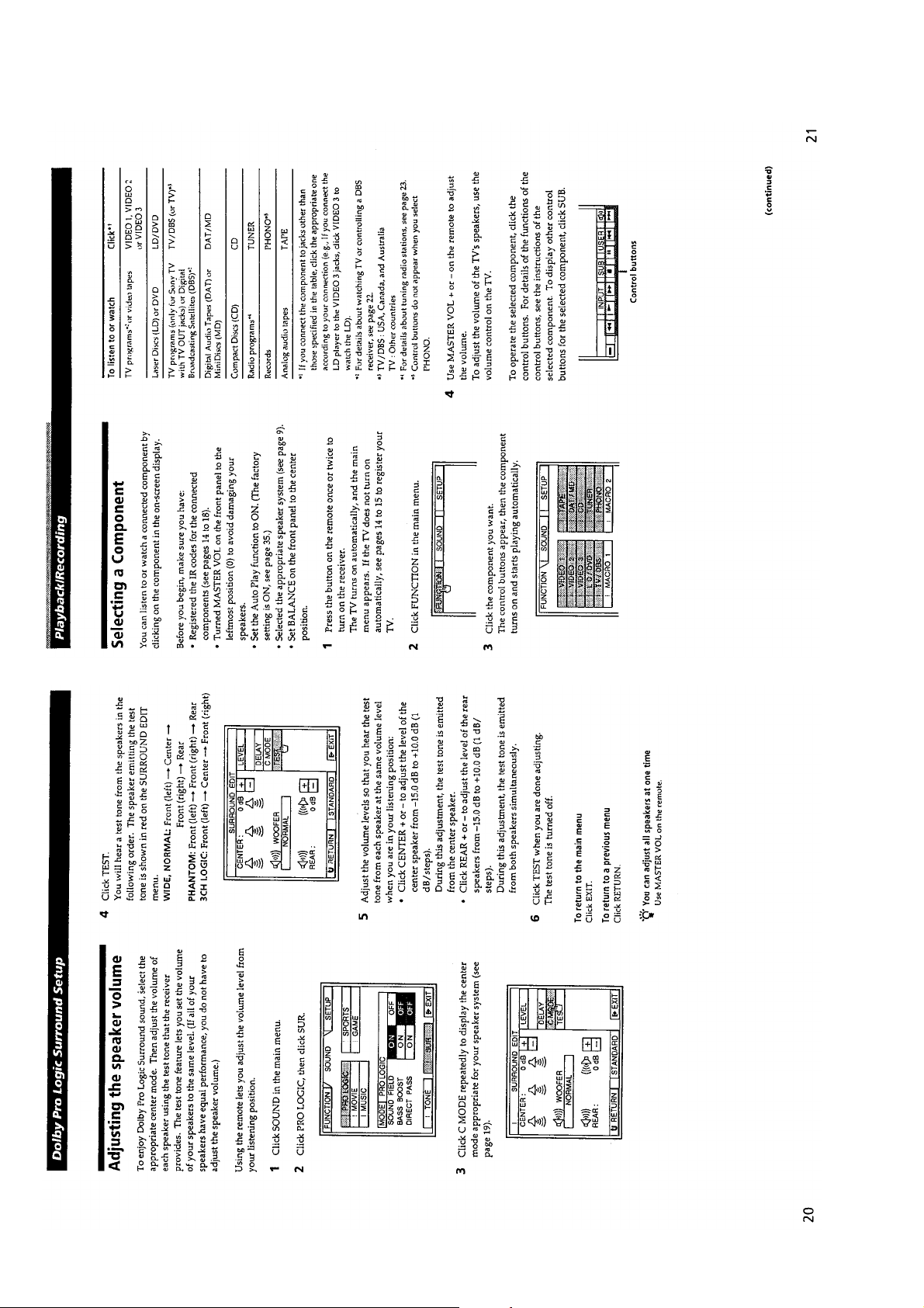
SPECIFICATIONS
— Continued on next page —
MICROFILM
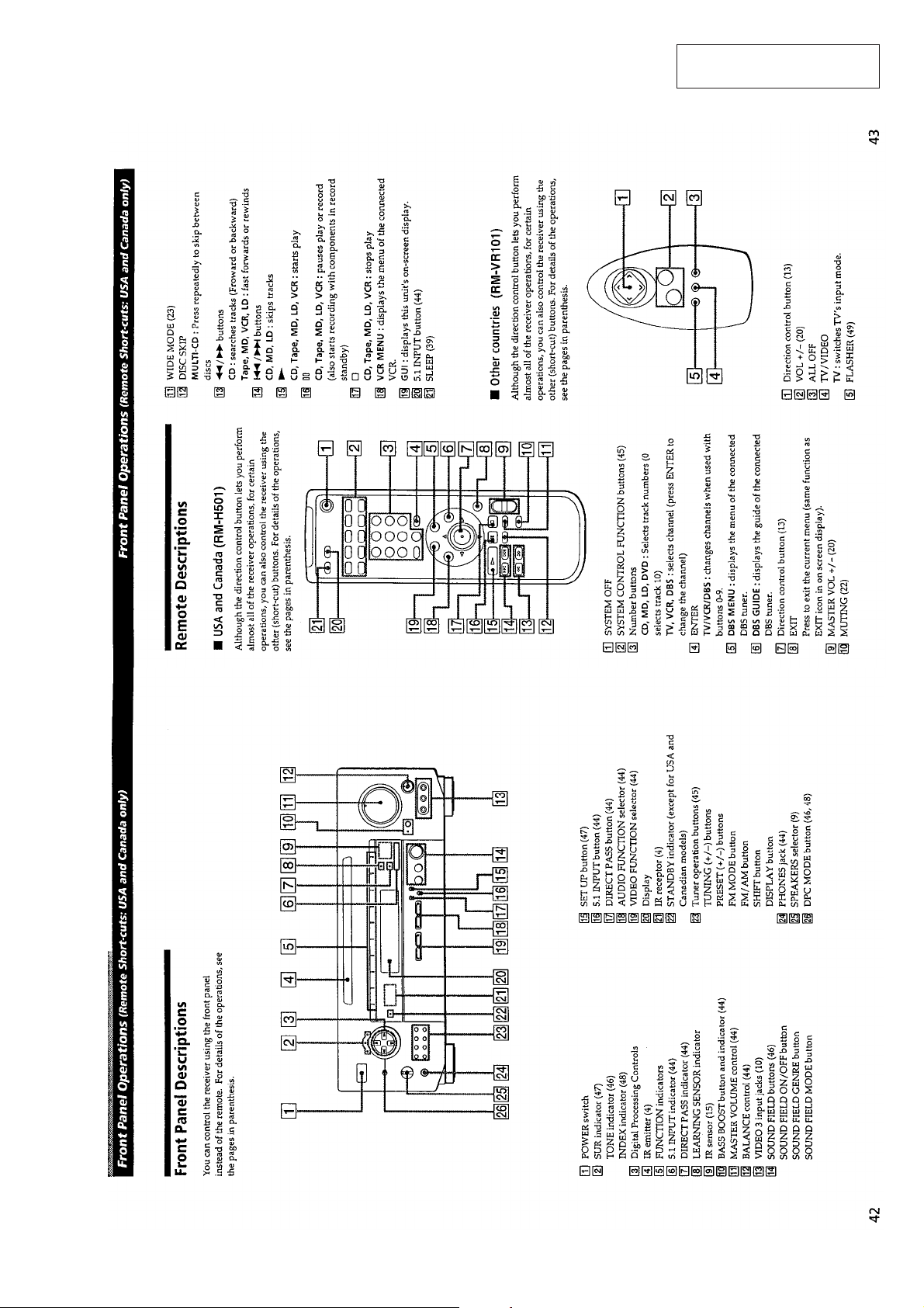
FM STEREO FM-AM RECEIVER
— 1 —
— 2 —
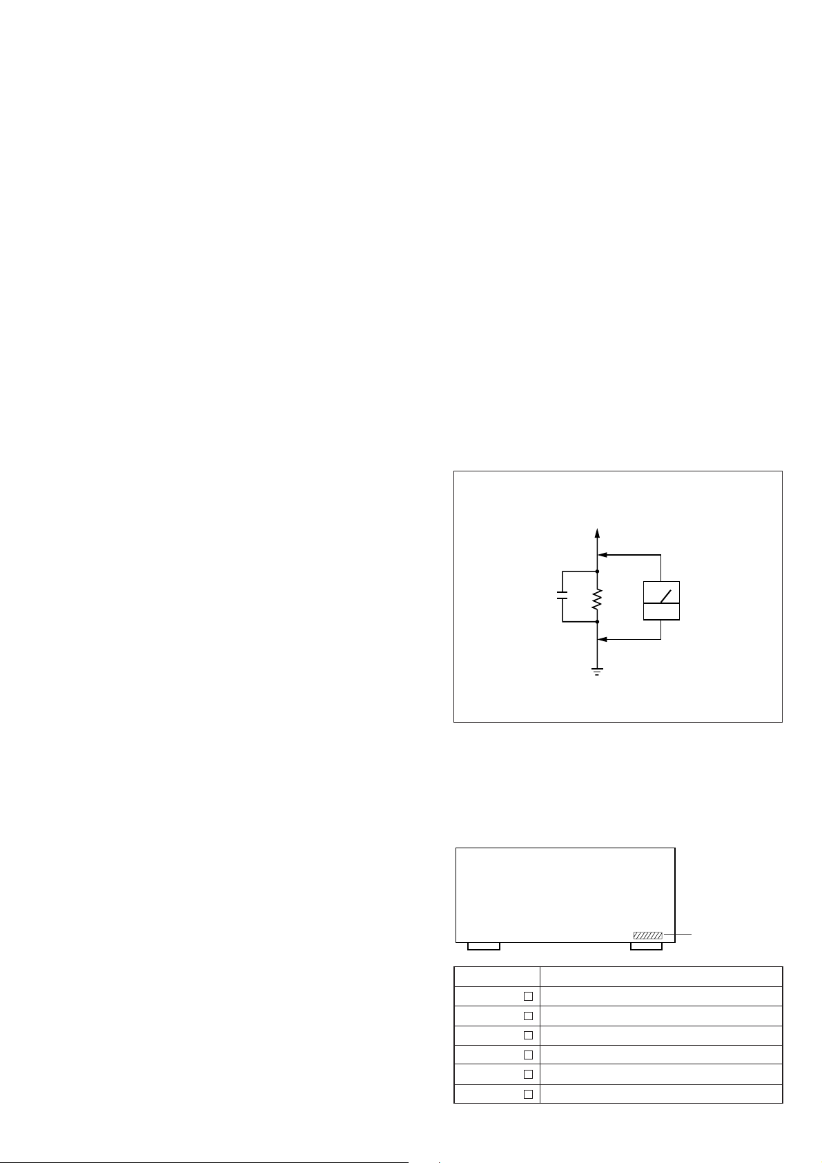
TABLE OF CONTENTS
SAFETY CHECK-OUT
1. SERVICING NOTE
.......................................................... 4
2. GENERAL .......................................................................... 5
3. DISASSEMBLY
3-1. Front Panel .......................................................................... 24
3-2. Balance Board, Display Board and Volume Board.............24
4. ELECTRICAL ADJUSTMENTS ............................... 25
5. DIAGRAMS
5-1. Circuit Boards Location ...................................................... 27
5-2. Block Diagrams
• Dolby Surround Section .................................................. 29
• OSD Section .................................................................... 31
• Power Amp Section .........................................................33
• Panel Section ................................................................... 35
• Power Section .................................................................. 37
5-3. Printed Wiring Board — Dolby Surround Section — ........ 40
5-4. Schematic Diagram — Dolby Surround Section — ........... 43
5-5. Schematic Diagram — OSD Section — ............................. 47
5-6. Printed Wiring Board — OSD Section —..........................51
5-7. Printed Wiring Board — Power Amp Section — ............... 55
5-8. Schematic Diagram — Power Amp Section —.................. 59
5-9. Printed Wiring Board — Panel Section — ......................... 63
5-10. Schematic Diagram — Panel Section — ......................... 67
5-11. IC Block Diagrams ........................................................... 70
5-12. IC Pin Functions ............................................................... 75
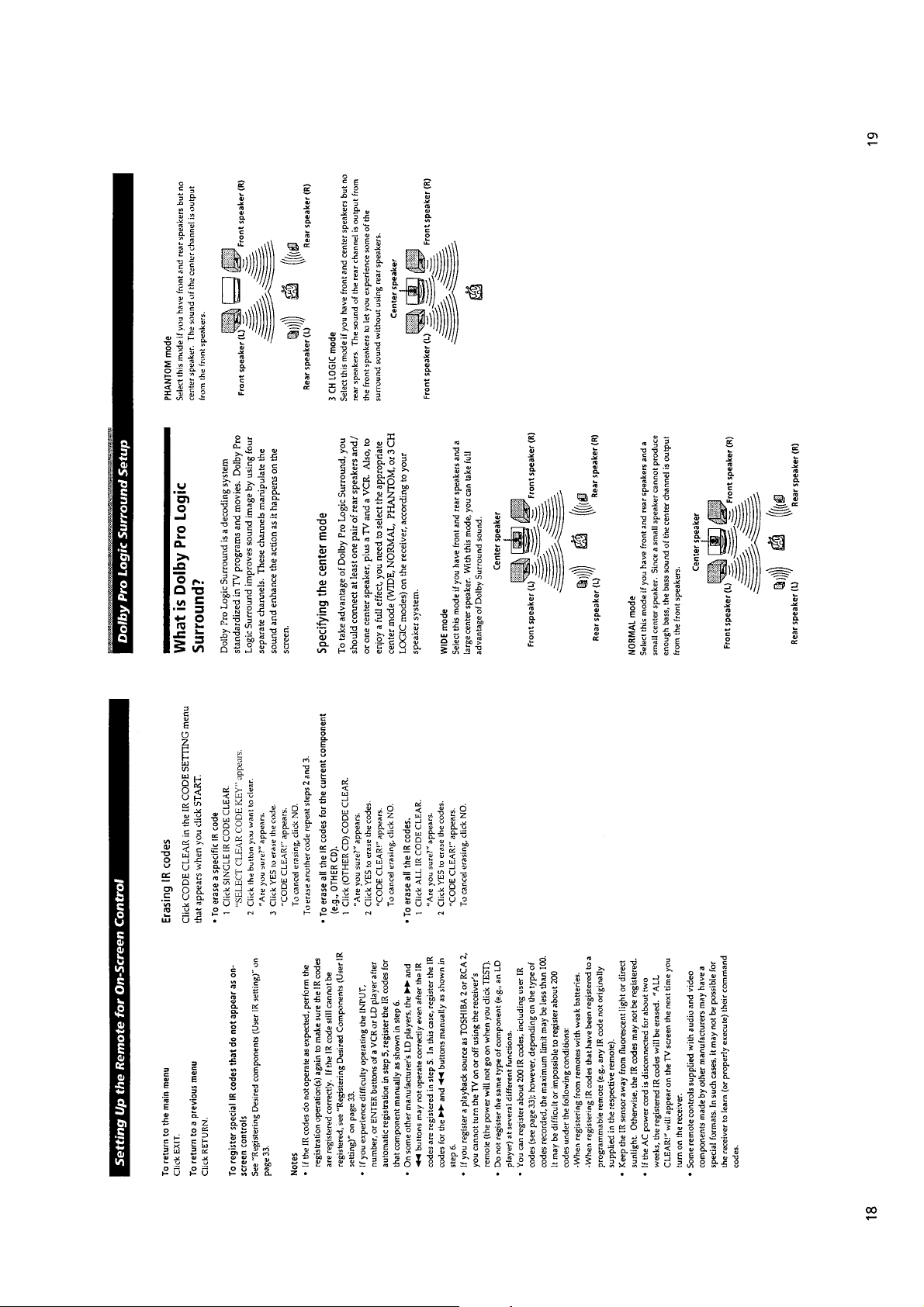
After correcting the original service problem, perform the following safety checks before releasing the set to the customer:
Check the antenna terminals, metal trim, “metallized” knobs, screws,
and all other exposed metal parts for A C leakage. Check leakage as
described below.
LEAKAGE
The AC leakage from any exposed metal part to earth Ground and
from all exposed metal parts to any exposed metal part having a
return to chassis, must not exceed 0.5 mA (500 microampers). Leakage current can be measured by any one of three methods.
1. A commercial leakage tester, such as the Simpson 229 or RCA
WT-540A. Follow the manufacturers’ instructions to use these
instruments.
2. A battery-operated AC milliammeter. The Data Precision 245
digital multimeter is suitable for this job.
3. Measuring the v oltage drop across a resistor by means of a V OM
or battery-operated A C v oltmeter. The “limit” indication is 0.75
V, so analog meters must have an accurate low-voltage scale.
The Simpson 250 and Sanwa SH-63Trd are examples of a passive VOM that is suitable. Nearly all battery operated digital
multimeters that have a 2V AC range are suitable. (See Fig. A)
To Exposed Metal
Parts on Set
6. EXPLODED VIEWS
6-1. Case Section........................................................................ 82
6-2. Front panel Section ............................................................. 83
6-3. OSD Board Section............................................................. 84
6-4. Chassis Section ................................................................... 85
7. ELECTRICAL PARTS LIST ........................................ 86
Notes on chip component replacement
• Never reuse a disconnected chip component.
• Notice that the minus side of a tantalum capacitor may be
damaged by heat.
SAFETY-RELATED COMPONENT WARNING !!
COMPONENTS IDENTIFIED BY MARK ! OR DO TTED LINE
WITH MARK ! ON THE SCHEMATIC DIAGRAMS AND IN
THE PARTS LIST ARE CRITICAL TO SAFE OPERATION.
REPLACE THESE COMPONENTS WITH SONY PARTS
WHOSE PART NUMBERS APPEAR AS SHOWN IN THIS
MANUAL OR IN SUPPLEMENTS PUBLISHED BY SONY.
ATTENTION AU COMPOSANT AYANT RAPPORT
À LA SÉCURITÉ!!
LES COMPOSANTS IDENTIFIÉS P AR UNE MARQUE ! SUR
LES DIAGRAMMES SCHÉMATIQUES ET LA LISTE DES
PIÈCES SONT CRITIQUES POUR LA SÉCURITÉ DE
FONCTIONNEMENT. NE REMPLA CER CES COMPOSANTS
QUE PAR DES PIÈCES SONY DONT LES NUMÉROS
SONT DONNÉS DANS CE MANUEL OU DANS LES
SUPPLÉMENTS PUBLIÉS PAR SONY.
0.15
Ω
µ
F
1.5k
Earth Ground
AC
voltmeter
(0.75V)
Fig. A. Using an AC voltmeter to check AC leakage.
MODEL IDENTIFICATION
— BACK PANEL —
Parts No.
Parts No.
4-989-884-6
4-989-884-0
4-989-884-1
4-989-884-2
4-989-884-3
4-989-884-4
D760Z : US model
DE815G : US model
DE815G : Canadian model
DE815G : E, PX model
DE815G : Singapore, Malaysia model
DE815G : Australian model
Model
— 3 —
SECTION 1
SERVICING NOTE
ALL CLEAR
Mode which erases all the user memories registered in this unit and
sets to setting at shipment.
Procedure:
1. With the power turned OFF, press the POWER button while
pressing the MODE button, AUDIO FUNCTION > and
VIDEO FUNCTION > button simultaneously to turn ON the
power.
2. ALL CLEAR ! will be displayed on the fluorescent indicator
tube, and ALL CLEAR will be executed.
FACTORY SET
Mode which sets the memory of the unit to the setting of adjustment and check at factory. (Not used for servicing.)
Procedure:
1. With the power turned OFF, press the POWER button while
pressing the MODE button and AUDIO FUNCTION > button
simultaneously to turn ON the power.
2. FACTORY SET will be displayed on the fluorescent indicator
tube, and FACTORY SET will be executed.
Note: In case you return the unit to the customer, do not perform
FACTRY SET. If you do it, perform ALL CLEAR.
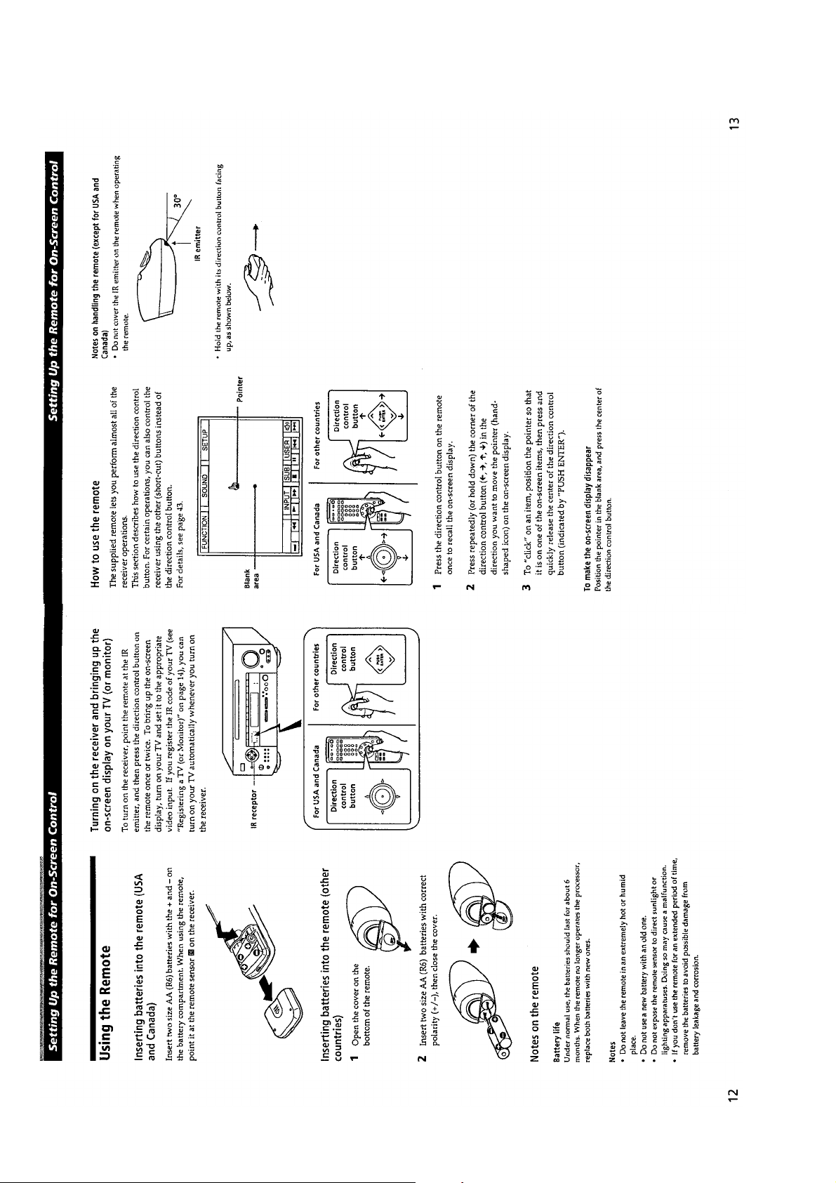
Fluorescent indicator tube, LED all lit mode
Adjustment of OSD Screen Position
The position of the screen can be adjusted freely to correct the deviation of the OSD screen caused by the monitor type that users are
using.
1. Move the cursor of the remote commander supplied as an accessory, and display the OSD screen.
2. Click the SET UP of the OSD screen.
3. Next click TV SET.
4. Next click GRAPHIC POSITION SET.
5. The screen for adjusting the OSD screen position will be displayed. Adjust the position with the remote commander supplied
as an accessory.
6. Click EXIT to end.
AM Tuning Step 9 kHz/10 kHz Selection
Method:
1. Tur n ON the power, set the AUDIO FUNCTION to AM, and
turn OFF the power.
2. While pressing the TUNING + button or PRESET TUNING +
button, press the POWER button.
3. “AM 9K STEP” or “AM 10k STEP” will be displayed on the FL
display tube.
Key Check Mode
Procedure:
1. With the power turned OFF, press the POWER button while
pressing the MODE button and VIDEO FUNCTION > b utton
simultaneously to turn ON the power.
2. The fluorescent display tubes and LEDs will all light up. Release the buttons in the order of VIDEO FUNCTION > , and
MODE .
3. The Fluorescent indicator tube display changes as follows by
pressing the A UDIO FUNCTION < , AUDIO FUNCTION > .
(Pressing the other buttons will exit this mode.)
9
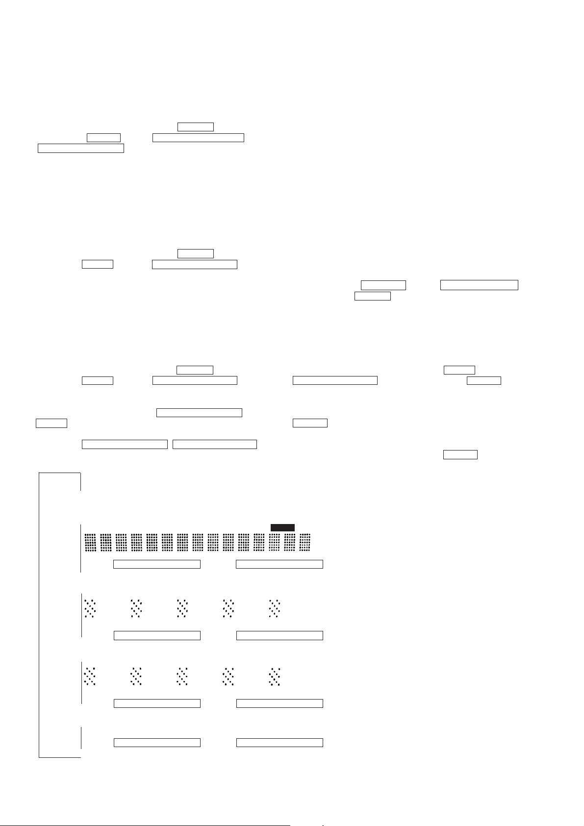
Fluorescent indicator tubes, LEDs are all lit
ENHANCED PRO LOGIC MONO MOVIE MUSIC 12 SPORTS GAME STEREO MONO
SML THEATER SML HALL ACOUSTIC KARAOKE ARENA STADIUM HIGH MEMORY
• Press AUDIO FUNCTION < button or AUDIO FUNCTION > button.
9
Partial lighting of fluorescent indicator tube 1, LEDs are OFF *1
• Press AUDIO FUNCTION < button or AUDIO FUNCTION > button.
9
Partial lighting of fluorescent indicator tube 2, LEDs are OFF *1
Method:
1. With the power OFF, while pressing the MODE button and
AUDIO FUNCTION < b utton together, press the PO WER button.
2. “KEY TEST [24]” will be displayed on the FL display tube.
3. The [XX] number is counted down each time a button other than
POWER is pressed until it becomes [00].
(Buttons pressed once will not be counted again when pressed
another time.)
4. When the number becomes [00], press the POWER button and
exit the mode.
• Press AUDIO FUNCTION < button or AUDIO FUNCTION > button.
Fluorescent indicator tube and all LEDs are OFF
*1 Those other than the POWER LED go OFF.
4. T o exit the mode, press the PO WER button to turn OFF the power .
9
• Press AUDIO FUNCTION < button or AUDIO FUNCTION > button.
9
— 4 —
SECTION 2
GENERAL
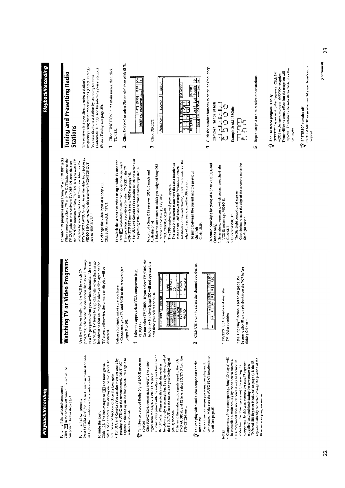
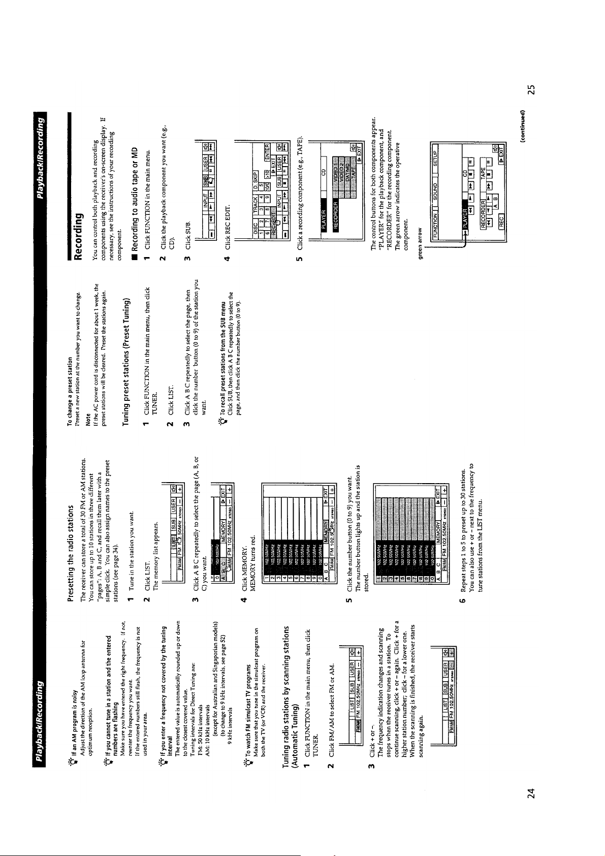
This section is extracted from
instruction manual.
— 5 —
— 6 —
— 7 —
— 8 —
— 9 —
— 10 —
— 11 —
— 12 —
— 13 —
— 14 —
— 15 —
— 16 —
— 17 —
— 18 —
— 19 —
— 20 —
— 21 —
— 22 —
 Loading...