

Page 1

3-756-703-21(2)
FM Stemo/FM-AM
Receiver
Operating Instructions
STR-D911
STR-D711
O 1993 by Sony Corporation
Page 2
Warning
WARNING
To prevent fire or shock hazard, do not
expose the unit to rain or moisture.
CAUTION
RISK OF ELECTRIC SHOCK
A
CAUTION: TO REDUCE THE RISK OF ELECTRIC SHOCK.
DO NOT REMOVE COVER (OR BACK).
NO USER-SERVICEABLE PARTS INSIDE.
REFER SERVICING TO QUALIFIED SERVICE PERSONNEL
This symbol is intended to alert the user to
the presence of uninsulated 'dangerous
voltage* within the product's enclosure that
may be of sufficient magnitude to constitute
a risk of electric shock to persons.
This symbol is intended to alert the user to
the presence of important operating and
maintenance (servicing) instructions in the
literature accompanying the appliance.
DO NOT OPEN
INFORMATION
This equipment has been tested and found to comply with
the limits for a Class B digital device, pursuant to Part 15 of
the FCC Rules.
These limits are designed to provide reasonable protection
against harmful interference in a residential installation.
This equipment generates, uses, and can radiate radio
frequency energy and, if not installed and used in
accordance with the instructions, may cause harmful
interference to radio communications. However, there is no
guarantee that interference will not occur in a particular
installation. If this equipment does cause harmful
interference to radio or television reception, which can be
determined by turning the equipment off and on, the user is
encouraged to try to correot the interference by one or
more of the following measures:
— Reorient or relocate the receiving antenna.
— Increase the separation between the equipment and
receiver.
— Connect the equipment into an outlet on a circuit
different from that to which the receiver is connected.
— (Consult the dealer or an experienced radio/TV
technician for help.
CAU'nON
You are cautioned that any change or modifications not
expressly approved in this manual could void your authority
to operate this equipment.
WARNING
To prevent shock hazard, do not insert the plug cut off from
the mains lead into a socket outlet. This plug cannot be
used and should be discarded.
Note to CATV system installer
This reminder is provided to call the CATV system
installer's attention to Article 820-40 of the NEC that
provides guidelines for proper grounding and, in
particular, specifies that the cable ground shall be
connected to the grounding system of the building, as
close to the point of cable entry as practical.
Owner's Record
The model number is located on the rear exterior and serial
number is on the rear. Record the serial number in the
space provided below. Refer to these numbers wrhenever
you call upon your Sony dealer regarding this product.
Model No. STR-D911 Serial No.
Model No. STR-D711 Serial No.
If the plug supplied with this appliance has detachable fuse
cover, be sure to attach the fuse cover after you change the
fuse. Never use the plug without the fuse cover.
If you should lose the fuse oover, please contact your
nearest Sony service station.
For the customers in Canada
1— CAUTION :------------------------
TO PREVENT ELECTRIC SHOCK, DO NOT USE THIS
POLARIZED AC PLUG WITH AN EXTENSION CORD,
RECEPTACLE OR OTHER OUTLET UNLESS THE
BLADES CAN BE FULLY INSERTED TO PREVENT
BLADE EXPOSURE.
This apparatus complies with the Class B limits for radio
noise emissions set out in Radio Interference Regulations.
Page 3

Table of Contents
Introduction
Overview
Precautions
Chapter 1 Getting Started
.................................................................
..............................................................
Unpacking................................................................5
Choosing a good location.......................................5
Checking the supplied accessories...........................5
Selecting the AM tuning interval
(except for Australian model)
...............................
Inserting the batteries into the remote commander.. 5
Hooking up the system...............................................6
Connecting audio equipment
Connecting video equipment
Connecting an FM antenna
Connecting an AM antenna
Connecting the antenna ground
Connecting speaker systems
Connecting to the AC power outlet
Identifying the parts and controls
.................................
.................................
....................................
...................................
.............................
..................................
.........................
................................
Front panel..........................................................9
Remote commander
(except for the STR-D911 for Canadian model)
Chapter 2 Basic Operations
Operating with the remote commander
.....................
Changing the settings of the FUNCTION buttons
Adjusting basic audio controls
...................................
.......
11
.......
12
Adjusting volume................................................12
Adjusting left and right sound balance
Adjusting tone from the front speakers
Reinforcing the bass
Selecting the speaker system
Selecting a program source
Labeling the program source
............................................
................................
.......................................
................................
...................
..................
12
12
12
12
12
13
To turn off the power at the desired time
(The sleep timer function)
..................................
13
Receiving broadcasts................................................14
Tuning in a station directly (Direct tuning)...............14
Scanning stations automatically (Automatic tuning).. 15
Presetting stations (Station preset)
Tuning in a preset station (Preset tuning)
Labeling the preset stations (Station index)
........................
.................
..............
Selecting a station among the preset stations in the
index (Index tuning)............................................19
Receiving FM simulcast TV programs
Recording an audio source
.........................................
Recording onto an audio tape deck or DAT deck
Tape dubbing
Editing a video source
Video tape dubbing
.....................................................
..............................................
............................................
.....................
......
21
21
Adding new sound on a video tape during video
editing.............................................................22
16
19
20
4
4
5
6
7
7
7
7
8
8
9
10
11
17
18
20
20
Chapter 3 Advanced Operations
Getting ready for Dolby surround sound
.....................
24
Placement of speakers and selecting the
PRO LOGIC MODE.............................................24
Adjusting the speaker volume
..............................
25
Adjusting the surround sound....................................26
Adjusting the delay time of the rear speakers..........26
Adjusting the surround effect
Sound field settings
..................................................
Available type of effects
Adjusting the tone controls
Adjusting the sound field programs
Calling up the sound field setting
...............................
.....................................
..................................
.......................
...........................
26
27
27
28
28
29
Linking the sound field memory to preset
stations or program source.................................29
Chapter 4 Other Information
Troubleshooting guide
Specifications
..........................................................
Quick reference
.............................................
.......................................................
30
32
34
Page 4

pntroducti^
Overview
The STR-D911/D711 is an FM Slereo/FM-AM receiver and
audio/video control center.
You can enjoy various audio/video program sources with
this unit.
TV/vIdeo programs
• You can enjoy TV or CATV programs with FM simulcast.
• Sounds from various audio program sources can be
added on video tapes during editing.
Tuner
• Precise tuning is ensured by a quartz locked digital
synthesizer.
• Station Index system allows you to tune into a station
quickly.
DOLBY PRO LOGIC
In the DOLBY SUR or THEATER mode, the Dolby* Pro Logic
can be selected. The Dolby Pro Logic Surround Decoder
has the same functions for playback as movie theaters and
gives a theater-like experience in your listening room,
naturally reproducing the audio sound field.
• Manufactured under license from Dolby Laboratories Licensing
Corporation. Additionally licensed under one or more of the
following patents: U.S. number 3,959,590: Canadian numbers
1,004,603 and 1,037,877. "DOLBY’, “Pro Logic", and the double-
D symbol are trademarks of Dolby Laboratories Licensing
Corporation.
Sound field (combination of digital delayed surround and tone controls)
• 7 recommended sound field programs (DOLBY SUR.
THEATER. LIVE. HALL. DANCE. SIMULATED.
ACOUSTIC) are preset in the factory for easy use. You
can also store up to 7 settings you created in the memory.
• Combined use of the sound fieid programs and the preset
stations or program source allow you to enjoy broadcast
or program source listening immediately with the
memorized 7 settings of sound field (DOLBY SUR.
THEATER, LIVE. HALL. DANCE. SIMULATED.
ACOUSTIC).
Precautions
On safety
• For the U.S.A. and Canadian models, operate the unit
only on 120 VAC. 60 Hz.
For Australian model, operate the unit only on 240 V AC,
50 Hz.
• Should any solid object or liquid fall into the cabinet,
unplug the unit and have it checked by qualified
personnel before operating it any further.
• Unplug the unit from the wall outlet if it is not to be used
for an extended period of time. To disconnect the cord,
pull it out by grasping the plug. Never pull the cord itself.
• One blade of the plug is wider than the other for the
purpose of safety and will fit into the power outlet only
one way. If you are unable to insert the plug fully into the
outlet, contact your dealer, (except for Australian model)
• AC power cord must be changed only at the qualified
service shop.
• This unit is not disconnected from the AC power source
as long as it is connected to the mains outlet, even if the
unit itself has been turned off.
On operation
Before making program source connections, be sure to
turn the power switch off and unplug the unit.
On cleaning the cabinet
Clean the cabinet, panel and controls with a soft cloth
lightly moistened with mild detergent solution. Do not use
any type of abrasive pad. scouring powder, or solvent such
as alcohol or benzine.
For the customers in the U.S.A.
For detailed safety precautions, see the "IMPORTANT
SAFEGUARDS* leaflet.
If you have any question or problem concerning your unit,
please consult your nearest Sony dealer.
Digital surround sound system (STR-D911 only)
The STR-D911 is equipped with a Digital Signal Processor.
All of 7 types of surround effect — DOLBY SUR, THEATER.
LIVE. H/\LL. DANCE. SIMULATED and ACOUSTIC have
been preset.
Remote commander
The supplied remote commander allows you to remotely
control this receiver and the equipments connected to the
receiver.
For the instruction of the remote commander for Canadian
model, see the operating instructions of the separate
volume.
Page 5
I
Chapter 1 Getting Started
Unpacking
Choosing a Good Location
To prevent internal heat buildup in the unit,
place the unit in a location with adequate air circulation.
Do not install the unit:
• near heat sources such as radiators or air ducts.
• in a place subject to direct sunlight, excessive dust,
mechanical vibration or shock.
Do not place anything on top of the cabinet.
The top ventilation holes must be unobstructed for the
proper operation of the unit and to prolong the life of its
components.
Do not throw away the carton and packing material!
It will be an ideal container when transporting the system for
repair work, etc.
Checking the Supplied Accessories
After unpacking, check that the following accessories are
present.
• FM wire antenna
................................................
(1)
• AM loop antenna................................................(1)
• Remote commander
• Sony batteries SUM-3 (NS)
...........................................
...................................
(1)
(2)
Selecting the AM Tuning Interval (Except for
Australian Model)
The AM tuning interval is preset to 10 kHz. To use the
receiver where the frequency allocation system is based on
a 9 kHz interval, make the following adjustments.
1 Turn on the power and tune in any AM station.
2 Turn off the power.
3 Press the POWER button while pressing the INDEX
SELECT/rUNING + button.
To reset the AM tuning interval, repeat the above steps.
Caution
When the interval is changed, all preset stations which you
have memorized will be erased. After changing the interval,
be sure to preset the stations again.
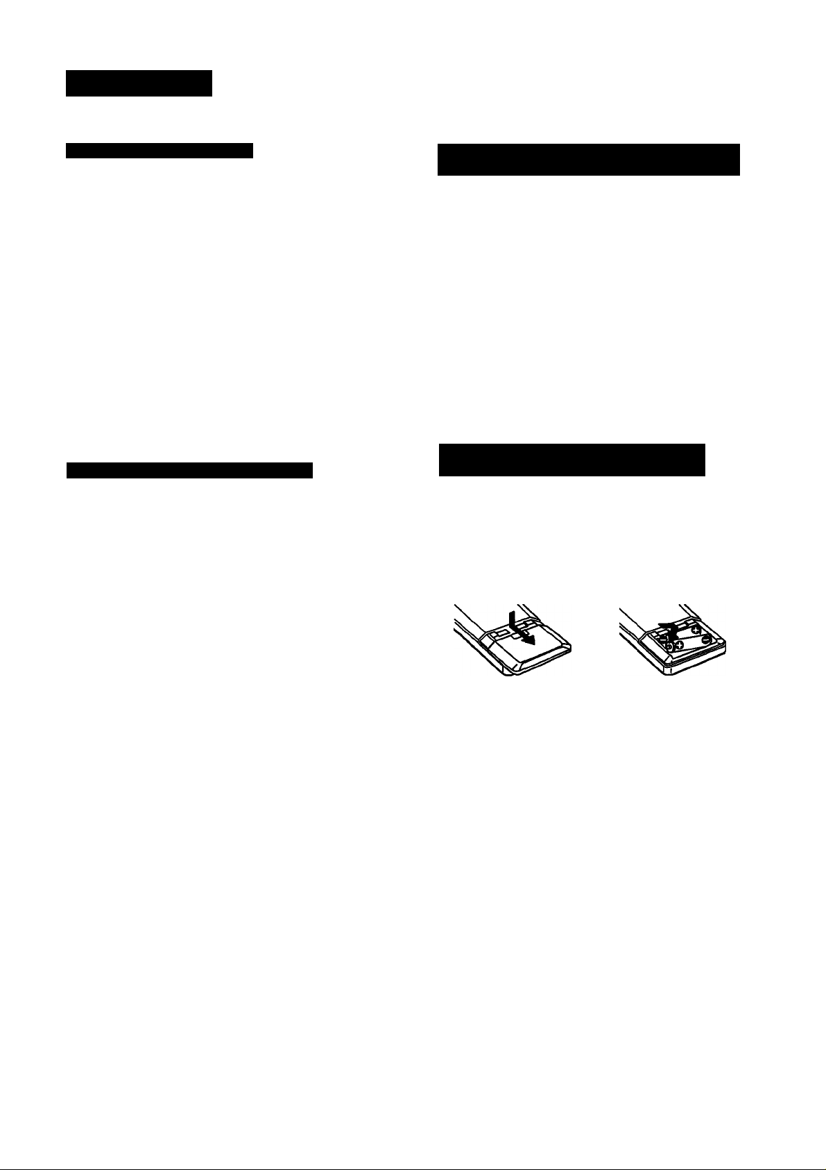
Inserting the Batteries into the Remote
Commander
Before operating remote commander, install the batteries as
shown.
1 Open the cover.
2 Insert two size AA (R6)
batteries with correct
polarity.
To avoid damage caused by battery leakage and corrosion
When the commander will not be used for a long time,
remove the batteries.
Battery life
Normal operation can be expected about a half year using
Sony SUM-3 (NS), and a year using Sony AM-3 (NW)
alkaline batteries.
When the batteries are run down, the remote commander
will not operate the unit. In this case, replace batteries with
new ones.
p. i ÎK v.ir-;-- i.ï i ;-i > 4; Ùh '.b'-'-:- r.i
Page 6
Hooking Up the System
At first, this section describes about the connection with the other equipments, the antenna
connection, speaker connection and then the AC power connection.
• Do not connect the power cord to an AC outlet nor press the POWER switch before
accomplishing all other connections.
• The cable connectors should be fully inserted into the jacks. Loose connection may cause
hum and noise.
• Jacks and plugs of the connecting cord are color-coded as follows;
Red jacks and plugs: For the right channel of audio signals
White jacks and plugs: For the left channel of audio signals
Yellow jacks and plugs: For video signals
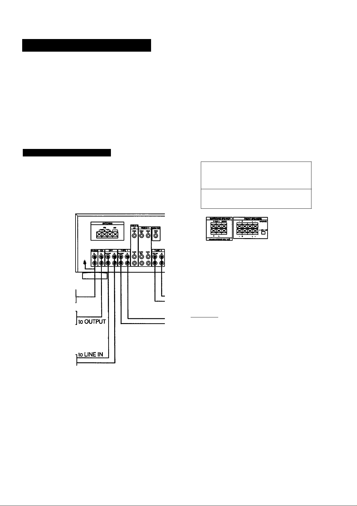
Connecting Audio Equipment
Turntable
CD player
to OUTPUT
R
m
to LINE OUT
to LINE IN
to LINE OUT
to LINE IN
Receiver
White White
Red Red
Other equipment
D
Tape deck
Tape deck 1
2
o>-»@L
DAT deck
to LINE OUT
Page 7

Connecting Video Equipment
Connecting an FM Antenna
Though the wire antenna is supplied with this unit, the
higher quality sound will be obtained with the 75-ohm
coaxial cable.
000
»« »
lololooloaol
oeoo
loowol
4
For normal use
KL.
For higher quality sound
Supplied wire
r antenna
75-ohm coaxial cable
(optional)
Connecting an AM Antenna
The AM broadcast is enough received with the supplied AW.
loop antenna. However, the connection of insulated wire is
also available for areas with difficult AM reception.
0»
Piolo oteolol
oo
00
9C
4
Supplied AM
loop antenna
'Adjust the
-«> direction.
For areas with difficuit AM reception
In areas with troubled reception, connect a 6 to 15-meter
(20 to 50-feet) insulated wire to the AM antenna terminal.
Extend this out of doors if possible, keeping the greater
portion horizontal.
(There is no need to disconnect the supplied antenna.)
300-ohm twin-lead
(optional)
Connecting the Antenna Ground
To prevent hum, connect the ground wire to ANTENNA
ground terminal (tJt).
When an outdoor antenna is installed, be sure to connect
the ground wire for lightning protection.
Page 8
Hooking Up the System
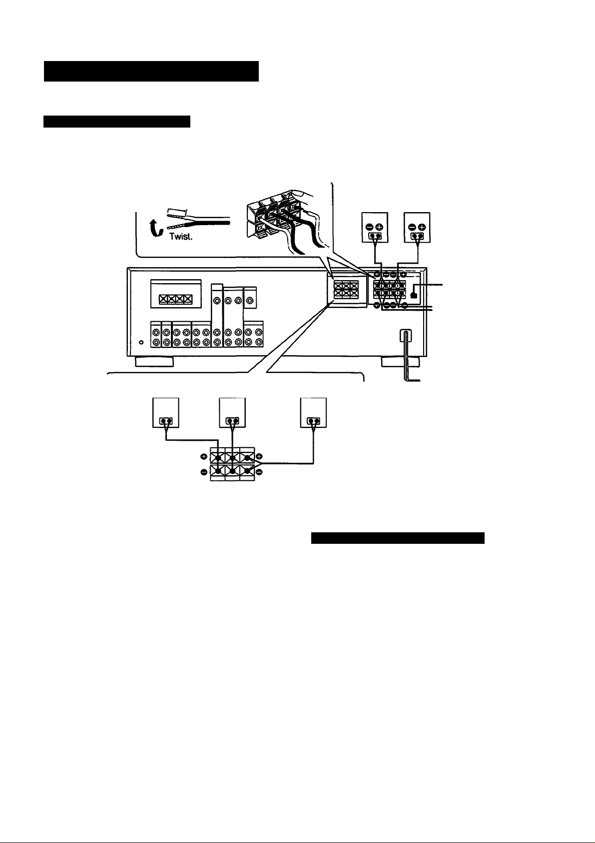
Connecting Speaker Systems
Front, rear and center speakers can be connected to this unit.
Approx. 15 mm
(’/,5 inches)
Rear Rear
speaker (R) speaker (L)
Front Front
speaker (R) speaker (L)
IMPEDANCE selector
(STR-D911 only)
^ to the second
front speaker
system
Center
speaker
On the IMPEDANCE selector (STR-D911 only)
The STR-D911 has the IMPEDANCE SELECTOR for front
speakers.
When using the front speakers having nominal impedance
from 4 ohms or higher, set to the 4 O position.
When using the front speakers having nominal impedance
from 8 ohms or higher, set to the 8 O position.
Note
Use the front speakers having nominal impedance of more
than 8 ohms in the SURROUND mode.
Note
When connecting the speaker cord to the speaker terminal,
make sure that the polarity (+ and -) of the speaker cord is
correct. If the polarity is reversed at either speaker, the
sound will be distorted and will lack bass.
8
Connecting to the AC Power Outlet
Connect the AC power cord to the wall outlet last of all.
By connecting the power cord of the other audio equipment
to SWITCHED AC OUTLET, this unit can supply the power
source to the other audio equipment.
Caution
Be careful that the total power consumption of each
equipment connected to the outlets on the receiver does not
exceed 120 watts (for U.S.A. and Canadian models) or 100
watts (for Australian model).
Do not connect electrical home appliances such as an
electric iron, fan, TV, or other high-wattage equipment to
these outlets.
Page 9
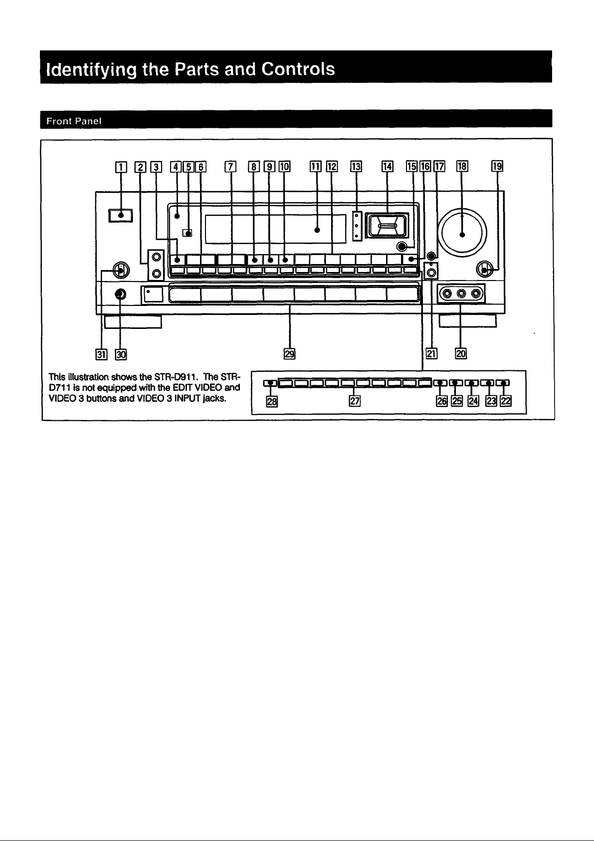
dl POWER switch
TONE ON/DEFEAT button (See page 28.)
11
m EDIT VIDEQ/AUDIO buttons (See pages 21, 22.23.)
(EDIT VIDEO button: STR-D911 only)
dl TUNING LEVEL (See page 15.)
S] STANDBY indicator
(The STANDBY indicator lights up when the power cord
is connected.: STR-D911 for Australian model only)
m Remote sensor
dl INDEX SELECrn’UNING buttons
(See pages 15.19.)
m PRESET TUNING +1- buttons (See pages 17,19)
[S SOUND FIELD UNK button (See page 29.)
m SOUND HELD ON/OFF button (See page 25.)
M PRO LOGIC MODE button
(See pages 24,25.)
mi Display window
H SOUND FIELD buttons (See pages 26. 27, 28, 29.)
D CURSOR MODE indicators
mi CURSOR MODEoperation buttons (See pages 13,18,
25, 26,28.)
DBFB button (See page 12.)
m
MASTER VOLUME control (See page 12.)
II
d
BALANCE control (See page 12.)
VIDEO 3 INPUT Jacks (STR-D911 only)
MU11NG button and indicator (See pages 12.)
DISPLAY button (See pages 15,18.19.)
FM MODE button (See page 14.)
DIRECT button (See page 14.)
FM/AM button (See pages 14,15.)
MEMORY button (See page 16.)
Numeric buttons (See pages 14,16,17,19.)
SHIFT button (See pages 16,17.)
Function selectors and TAPE 2 MONITOR button and
indicator (VIDEO 3 button: STR-D911 only)
(See pages 12,20.)
HEADPHONES Jack
SPEAKERS selector (See page 12.)
1
d CURSOR MODE button (See pages 13,18, 25.26, 28.)
9
Page 10
Identifying the Parts and Controls
Remote Commander (Except for The STR-D911
for Canadian Model)
^C3C3C]
a
Eh
E]—
rn Receiver control section
FUNCTION buttons
idocdci
o o o
O
o o o
CD
o o o
o o o
CDCDCDCD
mi—1 m m 1—11—1
O C3
0 O a
O
CD
CD
CD
CD
CD
a a
O CD
O CD
-m
DAT. CD. TUNER. PHONO. VIDEO 1. VIDEO 2. VIDEO
3. TAPE; The each function is selected and the each
unit enters its operating mode automatically.
SYSTEM OFF: Turns off the power of the whole system.
SOUND FIELD buttons
USER/PRE: This button does not function.
MODE: Selects the sound field mode.
ON/OFF: Turns on/off the sound field system.
m Other equipment control section
The operative buttons are changed according to the
function mode and the setting of the SYSTEM/TV
selector.
Numeric buttons (1 to 0): Designate the number.
>10; Designate the number more than 10.
ENTER: Press after designating the TV/VCR channel.
TV/VIDEO selector: Selects the TV program to see: TV
or VIDEO.
ANT TV/VTR button: Selects the output signal from the
antenna terminal on the VCR. either a TV signal or
VCR programs.
SHIFT: Select the memory page (A. B or C) only in the
TUNER mode.
CH/PRESET
+1-
buttons: Select a preset station of tuner
or a preset channel of TV/VCR.
INDEX: Select another index station.
◄ ◄ /► ► : fast winding/Manual search
•: Recording (Press • and or ► at the same time.)
◄ /► : Play
■ ; Stop
II: Pause
Locates a desired selection.
D (disc) SKIP: Disc skip (for a CD player equipped
with a multi-disc changer)
SELECT: Changes the settings of the FUNCTION
buttons.
VISUAL POWER: Turns on/off the power of TV. VCR and
LD player.
[H SYSTEM/TV mode switch
In TV mode (When setting the SYSTEM/TV selector
to TV.)
Only MUTING. M/VSTER VOL +/- and the operative
buttons in TV section on the list described on the next
page can be used.
BAND: This button does not function.
EQ: Turns on/off the setting of TONE controls.
T. (test) TONE: Generates a pink noise signal that is
sent in succession to each speaker.
CURSOR MODE: Select CURSOR MODE.
CURSOR operating buttons
REAR LEVEL +/- buttons: Control the volume of rear
speakers (surround level).
CENTER LEVEL +/- buttons: Control the volume of
center speaker (surround level).
DBFB button: Turns on/off the DBFS (Dynamic Bass
Feedback).
MUTING button; Mutes the sound.
MASTER VOL +/- buttons: Control the receiver
volume.
SLEEP: Set to the SLEEP timer mode. In this mode, the
unit is automatically turned off after the designated
time, (page 13)
Note
THe VIDEO 3 button functions only for the STR-D911.
10
Page 11
I
Chapter 2 Basic Operations
I
Operating with the Remote Commander
Before operating the equipments with the remote
commander, be sure to set the receiver to the desired mode
by pressing one of the FUNCTION buttons.
The FUNCTION buttons are factory s|et in the following list.
FUNCTION to be
pressed
DAT
CD CD player
TUNER Tuner '
PHONO (The receiver enters the PHONO mode.)
VIDEO 1
VIDEO 2
VIDEOS
TAPE
Operating equipment
DAT deck
BetamaxVCR(VCRI)
LD player
8 mm VCR (VCR 2)
Tape deck A
• When VIDEO 1,2 or 3 is pressed, the power of the
selected video equipment and TV i$ turned on.
Operating the equipment
1 Press the desired FUNCTION.
2 Press < (only for tape deck) or ► to start playback.
Changing the Settings of the FUNCTION Buttons
With the SELECT button, you can replace the functions
stored in the FUNCTION buttons.
To change the settings of the FUNCTION buttons
1 Press one of the FUNCTION buttons to be stored.
2 Press SELECT by using the pointed tool.
3 Press 1 to 9 button to select the desired function within 30
seconds.
To reset to the initial state, press Ihq >10 button.
With the numeric buttons from 1 to 9, the each function
can be selected as described below:
Numeric buttons
to be pressed
1
2
3 DECK A
4
5
6
7
8
9 VTR3
Note
The 0 and ENTER buttons do not function.
The function to be selected
CD player
DAT deck
DECKB
TV
LD player
VTR1
VTR2
list of operative buttons in SYSTEM mode (When setting
the SYSTEM/TV selector to SYSTEM
Operating
equipment
ENTER
SHIFT
TV/VIDEO
ANT TV/
PRESET
INDEX
D.SKIP
•4H-*
VISUAL
POWER
TUNER
1
2
3
4
5
6
7
8
9
0
>10
VTR
CH
+/-
► ►
«
II
•e —
►
■
CD DAT DECK
•
# •
•
• •
♦
• #
•
• •
•
• •
•
• •
♦
• •
•
• •
♦
• •
•
•
—
—
— —
—
—
—
•
— — —
•
—
— — — — —
•
—
•
—
•
—
—
—
—
—
—
—
—
—
•
•
•
# •
—
—
• •
— —
•
• •
—
A.B
—
—
—
—
—
—
—
—
—
•
—
—
— —
—
— —
—
—
—
—
—
— — — —
—
— — — —
•
•
♦
— —
— —
—
•
•
—
—
TV LDP
• • •
• • •
• • •
• • ♦
• • •
• • •
• • »
• • •
• •
• • %
•
• •* ••
•
•
—
•
—
•
—
•
—
•
—
•
— — —
•
—
•
—
•
VTR1,
2.3
•
• •
—
—
• •
• •
•
•
— —
—
• •
• •
• •
• •
♦
—
—
•
•
—
—
•
•; The button is operative.
—: The button is not operative.
•*: The button can operate TV.
Note
To operate the unit correctly, the function mode of the
receiver should be same with that of the remote
commander. So, be sure to press the desired FUNCTION
button at first and then the operative button.
Page 12

PâV* 11* I ■ t* ■ •T«
Controls
You can enjoy superb sounds using the audio adjustment
functions as shown beiow.
MASTER
SPEAKERS TONE DBFB VOLUME
Adjusting Volume
To adjust volume
Turn MASTER VOLUME.
To reduce the sound to a low level temporarily (- 20 dB attenuation)
Press MUTING. The indicator lights up.
Press again to restore the same listening level as before.
Adjusting Left and Right Sound Balance
Adjust BALANCE to correct stereo imaging, when the
speaker position is not symmetrical.
Selecting a Program Source
Turntable
CD player
Tape deck
DAT
VCR
LD player
1 Select the program source.
What you select
Phono record PHONO
Radto Broadcast
Compact disc CD
TUNER
Press
Adjusting Tone from the Front Speakers
Press ACOUSTIC so that ACOUSTIC appears on the
dispaly and then press CURSOR MODE so that the TONE
indicator lights up. Press < or > to select BASS or
TREBLE respectively and then press A or v to adjust the
level.
Reinforcing the Bass
Press DBFB (Dynamic Bass Feedback) so that DBFB ON
appears on the display. Press again to turn off the effect so
that DBFB OFF appears on the display.
Selecting the Speaker System
To drive speaker system A: Set SPEAKERS to A.
To drive speaker system B; Set SPEAKERS to B.
To drive both speaker systems A and B (series
connection); Set SPEAKERS to A + B.
For headphone listening: Connect headphones to
HEADPHONES and set SPEAKERS to OFF.
IMPORTANT
Speaker systems A and B are series connected. When
only one speaker system is connected, no sound can be
heard at the A + B position.
DAT program
Taped program TAPE 1, TAPE 2 MONITOR
Video program
When a function selector is pressed, the indicator
of the function you have selected appears on the
display.
Select the function with the remote commander,
the power switches of both this receiver and the
selected equipment are turned on.
DAT
VIDEO 1, VIDEO 2/LD,
VIDEO 3(STR-D911 only)
12
Page 13

Labeling the Program Source
You can input program sources under index names you
create (up to 11 characters); for example, PHONO. TUNER,
CD etc.
Select the program source.
2 Press CURSOR MODE to select the INDEX
mode.
To Turn Off the Power at the Desired Time
(The Sleep Timer Function)
This function can be operated only with the remote
commander.
This receiver has the sleep timer function. With this
function, you can turn off the power automaticaiiy at the
desired time by designating the turn-off time.
Press SLEEP on the remote commander when the power is
on. Each time SLEEP is pressed, the designating time is
displayed in the following order: 2 hours -♦ 1 hour and 30
minutes -► 1 hour -♦ 30 minutes -► SLEEP OFF.
CURSOR MODE
The INDEX indicator iights up.
Create an Index name.
b
To select a letter (A to Z) or number (1 to 9), press
Aor V.
To change the position, press < or >.
Repeat steps 1 to 3 for all other program
sources you want to assign an index name to.
If you input an already store source under any other
Index name
Only the last selected index name will be valid. Each
program source can be stored under only one index name.
To change the turn-off time
1 Press SLEEP and the remaining time is displayed.
2 Press A or V to change the sleep time. The sleep time is
changed by 1 minute. It can be changed up to 5 hours.
To check the remaining time of the sleep timer
Press SLEEP. The remaining time is dispiayed.
To switch the display mode between the original
function name display and created index name display
Each time the DISPLAY is pressed, the selected function
name (which corresponds to the function seiector) and the
created index name are aiternately displayed.
1G
Page 14

Receiving Broadcasts
Tuning in a Station Directly (Direct Tuning)
I POWER-»-on]
1 Press TUNER.
TUNER
TUNER frequency appears on the display.
Select FM or AM.
FM/AM
“6
Press DIRECT.
DIRECT
15
To correct the entered frequency
Repeat steps 3 to 4.
For entering AM frequencies
You need not enter the last *0*. (Except for Australian
model)
However, if you have changed the AM tuning interval to 9
kHz, enter all the digits.
If you enter a frequency not covered by the tuning Interval
The entered value is automatically rounded up or down to
the closest value covered by the tuning interval.
Tuning intervals for direct tuning are the followings:
FM: 50 kHz interval
AM: 10 kHz interval (changeable to the 9 kHz interval)
(See page 5)
9 kHz interval only for Australian model.
When the entered frequency does not exist in the receivable frequency range
The entered digits blink as follows in the frequency display
area, and reception does not take place.
U.S.A. and Canadian models:
Up to 5 digits for FM or up to 3 digits for AM
Australian model:
Up to 5 digits for FM or up to 4 digits for AM
if this occurs, press DIRECT again, and enter the correct
frequency. The frequency range of the receiver is 87.50 to
108.0 MHz for FM, and 530 to 1710 kHz (U.S.A. and
Canadian models) or 531 to 1602 kHz (Australian model) for
AM.
When an FM stereo program is noisy
When the unit receives an FM stereo program, the STEREO
indicator lights on the display. If the stereo program is noisy,
press FM MODE to change ttie mode over the MONO. This
eliminates the stereo effect, but the noise will be greatly
reduced.
To return to the stereo mode, press FM MODE again.
4 Enter the frequency.
Eizi mz] nzzi i^zi [^zi [izzi I
b
The entered frequency is displayed.
Example 1: FM 102.50 MHz Example 2: AM 1350 kHz
02.BOMHi
14
dE'UKHi
Page 15

15
Page 16

Receiving Broadcasts
Presetting Stations (Station Preset)
A total of 30 FM/AM stations can be memorized in any
desired sequence.
Press TUNER.
1
TUNER
5 While MEMORY appears, press the desired
number.
|2 |[3 IP |[i Ifi IF
<5
Repeat above steps for presetting other desired
stations.
Replacing a preset station
Preset another station on the number of the station to be
replaced. The previously preset statton will be erased.
15
TUNER frequency appears on the display.
2 Tune in the desired station.
(See “Direct Tuning" or "Automatic Tuning" on
pages 14 and 15.)
Press MEMORY.
MEMORY
15
MEMORY appears on the display.
4 While MEMORY appears, select the memory
page (A, B or C).
.SHIFT
15
Each time SHIFT is pressed, A. B or C is indicated
cyclically on the display.
16
Page 17

Tuning in a Preset Station (Preset Tuning)
There are two ways to perform the preset tuning.
In method A, the direct tuning, selectjby designating the
desired preset station number directly with the numeric
buttons. In method B, the scan tuning, select the preset
station with the PRESET TUNING +/-button.
Method A: Direct tuning
power-on] g
1 • I
1
Press TUNER.
TUNER
15
TUNER frequency appears on the display.
Select the memory page (A, B, or C).
SHIFT
15
Each time SHIFT is pressed, A,B or C is
indicated cyclicallly on the display.
Designate the desired preset station number
with the numeric buttons.
117 |[3 IP llf
IMPORTANT
The memorized station is maintained for approximately one
month even if the power cord is disconnected from the AC
power outlet. If they are erased, store the stations again.
\n
b
17
Page 18

Receiving Broadcasts
Labeling the Preset Stations (Station Index)
You can divide preset stations under index names you
create (up to 5 characters). If you want to categorize the
preset stations by kinds of music, for example, create
indexes such as ROCK, JAZZ, etc.
5 Repeat steps 2 through 4 for ali other stations
you want to assign an index name.
If you store an already categorized station under any other index name
Only the last selected category will be valid. Each station
can be stored under only one index name
To display the frequency and index name of preset stations
Each lime DISPLAY is pressed, frequency and index name
of the preset station are alternately displayed.
Press TUNER.
TUNER
15
TUNER frequency appears on the display.
Tune in the desired station with Preset Tuning.
3 Press CURSOR MODE to seiect the iNDEX
mode.
CURSOR MODE
The INDEX indicator lights up.
Create an index name.
--------
To select a letter (A to Z) or number (1 to 4), press
Aor V.
To change the position, press < or >.
18
Page 19

Selecting a Station among the Preset Stations in
the Index (Index Tuning)
Receiving FM Simulcast TV Programs
Press TUNER.
TUNER
TUNER frequency appears on the display.
Press DISPLAY to set to the index mode.
DISPLAY
B
When no index name is memorized, "no-index"
appears on the display.
Select the desired station.
• To select a station in the same index:
PRESET TUNING
For lower channnel For higher channel
index station index station
7^
1 Select VIDE01, VIDEO 2fLD or VIDEO 3 (STR-
D911 only).
VIDEO 1. VIDEO 2/LD or VIDEO 3 appears on the
display.
According to video inputs connected to an
equipment to which the VHF antenna is connected.
Turn on the monitor TV.
Select the desired program on the TV tuner or №eVCR.
Select TUNER and tune in the FM simulcast TV program on the receiver.
TUNER
B
ir~~IP 1ls If« ir
b
• To select a index station other than the displayed
index station:
INDEX SELECT/rUNING
b
PRESET TUNING
T
For lower
channel
■X
For higher
channel index
Page 20

Recording an Audio Source
Recording onto an Audio Tape Deck or DAT Deck
Audio signals
1 Select the desired program source with the
function selector.
For an FM/AM broadcast, tune in the desired station
Tape Dubbing
Audio signals
Tape deck 2
(for recording)
Tape deck 1 or
DAT deck
(for playback)
1 insert the recorded tape into tape deck 1 (or the
DAT deck).
Set the tape (DAT) deck in the recording mode.
Start playback of the selected program source.
Note on recording
For TAPE 1, 2 and DAT REC OUT jacks, the settings of
SOUND FIELD and DBFS do not have any effect on
recording.
Monitoring the recorded sound
If you have connected a 3-head tape deck to the TAPE 2
jacks, you can monitor the recording results. While
recording or dubbing, press TAPE 2 MONITOR so that the
TAPE 2 MONITOR indicator lights up. To listen to the source
sound again, press the button again so that the indicator
goes off.
2 insert a blank tape into tape deck 2 and adjust
the recording level.
Press TAPE 1 or DAT to select the deck for playback.
4 Set tape deck 2 In the recording mode and then
start playback of the tape (or the DAT) on tape
deck 1 (or the DAT deck).
Dubbing will start.
Note on tape dubbing
Tape dubbing is possible only in the following directions:
From
(playback deck)
Tape deck
connected to
TAPE 1 IN
DAT deck
connected to
DAT IN
Tape deck connected to TAPE 2 OUT
DAT deck connected to DAT OUT
Tape deck connected to TAPE 1 or 2
OUT
To
(Recording deck)
20
Press the function selector according to the playback deck.
Page 21

Editing a Video Source
Video Tape Dubbing
If the AUDIO indicator is lit on the display, press the EDIT
AUDIO button to make the indicator go out.
With the STR-D911
^ Video signals
POWER -► ON
vdR11 3
4 TV tunerA/CR 2
to VIDEO 2
VIDEO IN/
AUDIO IN
to VIDEO 1 VIDEO
OUT/AUDIO OUT
to VIDEOS
VIDEO IN/
AUDIO IN
iV tuner/VCR 3 4
To iisten to an audio program during video tape dubbing
1 Press the appropriate function selector.
2 Start the selected audio program source.
With the STR-D711
Video signals
POWER • "oFI]
VCR1 2
3 TV tuner/VCR 2
to VIDEO 2
VIDEO IN/
to VIDEO 1 VIDEO
OUT/AUDIO OUT
AUDIO IN
(Zl
O
Select the playback VCR with EDIT VIDEO.
To select VCR 2. press EDIT VIDEO so that ‘2> 1"
appears on the display.
To select VCR 3, press EDIT VIDEO so that “3> 1“
appears on the display.
Press VIDEO 2/LD or VIDEO 3 to select the video signai to monitor on the monitor TV according to the VCR to be piayed.
VIDEO 2/LD-.for the VCR 2
VIDEO 3: for the VCR 3
Set the VCR 1 in the recording mode.
4 Set the piayback VCR in the piayback mode.
Dubbing will start.
— Video editing —
To switch the playback VCR during dubbing
Press EDIT VIDEO. Each time you press the button, the
playback VCR switches from the VCR g to the VCR 3 (or the
VCR 3 to the VCR 2).
Press VIDEO 2/LD.
Set the VCR 1 in the recording mode.
Set VCR 2 in the playback mode.
Dubbing will start.
To listen to an audio program during video tape dubbing
1 Press the appropriate function selector.
2 Start the selected audio program source.
To record a TV program
You can record a TV program on VIDEO 1.
To view the other video source(s) on the monitor TV
during dubbing
Press the appropriate function selector, VIDEO 1, VIDEO 2/
LD. or VIDEOS.
Page 22

Editing a Video Source
Adding New Sound on a Video Tape during Video
Editing
During video tape editing, you can add the desired sound
on the recording VCR from various audio program sources.
With the STR-0911
^ Videosignals
Audio signals
VCR 1 I 6
to VIDEO 1
VIDEO OUT/
AUDIO OUT
Select the audio program source with the
function selectors.
G Set VCR 1 in the recording mode and then
release the pause mode of VCR 2.
Start playback of the selected audio program source.
Video dubbing starts and the audio program
source is also recorded on the VCR 1
simultaneously.
1
Select the playback VCR with EDIT VIDEO.
To select VCR 2, press EDIT VIDEO so that '2> 1'
appears on the display.
To select VCR 3. press EDIT VIDEO so that *3> 1"
appears on the display.
Set the playback VCR to the playback mode.
3 At the point where audio dubbing starts, press
the pause button on the playback VCR.
Press EDIT AUDIO.
AUDIO appears on the display.
22
Page 23

With the STR-D711
POWER ON
VCR 2 2, 3, 6
o r~ r" i"| 1 1 m I
1
Press VIDEO 2/LD.
to VIDEO 2
VIDEO IN
U ■ ■■ ■ 'iBl
I ------------------------- i e
-------------------------------------
Videosignals
! Audio signals
VCRJJ 6
to VIDEO 1
VIDEO OUT/
AUDIO OUT
1 o
Turntable
CD player
Tape deck~|
DAT deck
Start playback of the selected audio program
source.
Audio dubbing wiil start.
2 Insert a recorded video tape'into VCR 2 and
set the VCR to the playback mode.
3 At the point where audio dubbing starts,
press the pause button on VCR 2.
Press EDIT AUDIO.
AUDIO appears on the display.
S Select the audio program source with the
function selectors.
G Set VCR 1 in the recording mode and then
release the pause mode of VCR 2.
23
Page 24

^ Chpater 3 Advanced Operations
Getting Ready for Dolby Surround Sound
This section describes about seiecting the speaker
configuration and then adjusting the speaker volume and
the delay time of the rear speakers so that you can enjoy
the Dolby surround sound.
Placement of Speakers and Selecting the PRO
LOGIC MODE
The Dolby Pro Logic Surround Decoder has the same
functions for playback, such as movie theaters and gives a
theater-like experience in your listening room, naturally
reproducing the audio sound field.
The STR-D911/D711 incorporates a decoder which
reproduces the specially encoded surround sound of Dolby
surround video programs.
In the DOLBY SUR or THEATER mode, select the speaker
operation mode according to your speaker configuration by
pressing the PRO LOGIC button. Each time the PRO
LOGIC button is pressed, the PRO LOGIC mode is
changed in the following order:
p PHANTOM -► 3 CH. LOGIC — NORMAL — WIDE-|
3CH. (Channel) LOGIC mode
Select this mode when you play back a Dolby surround
program source only with the front and center speakers.
The sound of the rear channel is output from the front (L and
R) speakers.
NORMAL mode
Select this mode if you use a small center speaker. The
bass sound of the center channel is output from the front
speakers, as a small speaker cannot produce enough bass.
PHANTOM mode
Select this mode when you play back a Dolby surround
program source without using a center speaker. The sound
of the center channel is output from the front (L and R)
speakers.
24
WIDE mode
Select this mode if you use a medium to big center speaker.
Some commercially available software may have Dolby
surround processed sound tracks even though it is not so
indicated on the package.
Page 25

Getting Ready for Dolby Surround Sound
Adjusting the Speaker Volume
5 Press CURSOR MODE.
To enjoy the surround sound to the maximum on playing any
program sources, adjust the front, center, and rear (if
connected ) speakers to the same volume level. The
adjustment must be done with a test tone in the DOLBY SUR
mode, but the level once adjusted can be used for all
surround modes.
You can adjust the volume level from your listening position
by using the remote commander.
The SUR (surround) indicator lights up.
To adjust the level of center speakers
Press A or V to select the center level mode and
then adjust the level with < or > or CENTER LEVEL
+/- on the remote commander so that sound from
each speaker is heard in the same volume level at
the listening position. (When adjusting the VOLUME
control on the receiver, all speakers are adjusted
simultaneously.)
To adjust the level of rear speakers
Press A or V to select the rear level mode and then
adjust the level with < or > or REAR LEVEL +/- on
the remote commander.
Press T. TONE on the remote commander to set
to off.
Press SOUND FIELD ON/OFF to ON.
The last selected sound field is displayed in box.
I DOLBY SURI
THEATER
LIVE
HALL
DANCE
SIMULATED
ACOUSTIC
2 Press DOLBY SUR.
DOLBY SUR appears on the display.
Select the Dolby pro logic mode with the PRO LOGIC button according to your speaker system.
Sequence of the test tone
In a system with a center speaker:
The test tone will be output automatically from the front L,
center, front R, and the rear speakers in succession.
Front left
Center
Front right
/
Q
tsCH. LOGIC j
L
NORMAL and WIDE modes
Rear left and right
J
S'
In a system without a center speaker:
The test tone will be output automatically from the front left
and right speakers and the rear speakers alternately.
Press T. TONE on the remote commander to set toon.
The receiver is preset in the factory to get an optimum
surround level as long as each speaker has an equal
efficiency.
25
Page 26

Adjusting the Surround Sound
Adjusting the Delay Time of the Rear Speakers
— for DOLBY SUR (Dolby surround) mode
The delay time is a time between the surround sound from
the front and that from rear speakers. The delay time is
adjustable from 15 ms to 30 ms. For adjusting the delay time
of the rear speakers except for the DOLBY SUR mode, see
page 27.
POWER ON
4
2 3,
1 O
o SU-MMJUjJ
o Q l 1 1 1 1 1 1 II..J
'•Ik
Mmo
5l Ch
Adjusting the Surround Effect
Press the desired SOUND FIELD program.
2 Press CURSOR MODE.
The SUR (surround) indicator lights up.
Press A or V to select the desired parameter.
1 Press DOLBY SUR.
DOLBY SUR appears on the display.
2 Press CURSOR MODE.
The SUR (surround) indicator lights up.
Press A or V to select the delay time mode.
Press < or > to adjust the delay time.
To turn off the surround effect
Press SOUND FIELD to OFF.
The normal sound without surround effect will resume.
Both level and delay time of the surround is memorized
each time after adjusting with the cursor operation buttons.
They will be restored when the surround mode is resumed.
Note
The delay time for the rear speakers can be adjusted even
in the 3 CH. LOGIC mode.
Press < or > to adjust the parameter.
26
Page 27

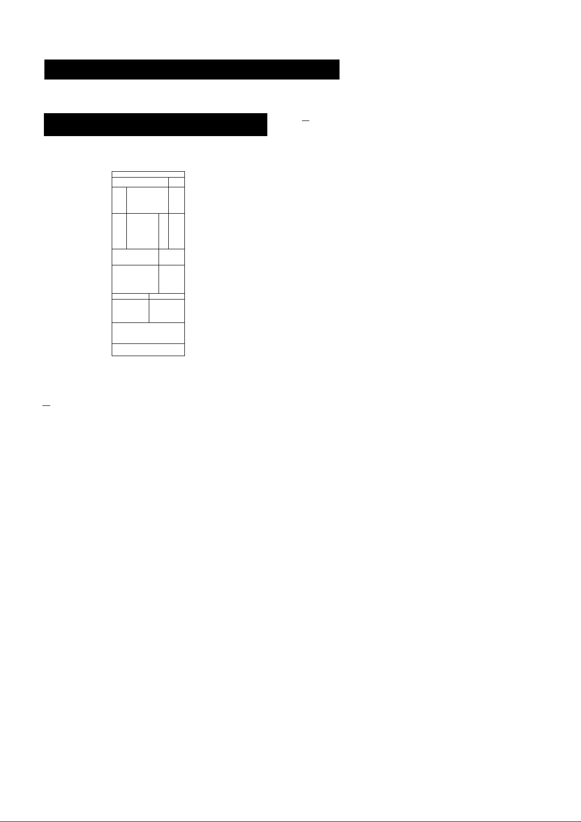
Sound Field Settings
Available Type of Effects
7 recommended sound field programis (combination of the settings of the surround and tone control.) have been preset in the
factory. Since these programs are appropriate for the most type of music and listening situations, you can enjoy the sound
effect by selecting the desired sound ;field program according to the program source. And you can also manipulate various
parameters to finely tune the factory-preset settings to your room, or create original sound effects as you like.
^—._._^und field
Parameter^
Tone
Delay time
1
o
E e
(0 i
On the Digital Signal Processor (ST^-D911 only)
Rear level
Center level
Effect level
(STR-D911 only)
DOLBY SUR THEATER LIVE
• ,
•
• •
•
1
•
•
•
•
The STR-D911 incorporates Digital Signal Processor. The
digital signal processor electrically reproduces the 7 kinds
of surround sound field programs whibh have been preset in
the factory. I
DOLBY SUR: Decodes programs processed with the Dolby
surround.
THEATER: Adds the reflection of a theater to decoded
signals of the Dolby pro logic decoder.
HALL DANCE SIMULATED
• • •
• • •
• •
•
Effect Level
•
•
•
•
•
•
ACOUSTIC
•
Effect level is the combination of the level of early reflections
and reverberation. The adjustable level is divided into 11 (0
-10) segments. As you select higher level, the room
becomes more 'live*, and as you select lower level, the room
becomes 'dead'.
LIVE: Reproduces the acoustics of a large concert hall. It is
effective for playing a program source with hard sound.
HALL: Reproduces the acoustics of a rectangular concert
hall with soft sound.
DANCE: Boosts high and low frequencies and the dynamic
sounds are reproduced.
SIMULATED: Gives a simulated stereO effect to monaural
sound.
ACOUSTIC: The surround effect is defeated and only the
tone control is available. !
Adjusting the delay time of the rear speakers (Except for DOLBY SUR mode)
STR-D911
THEATER, DANCE, SIMULATED: 6-51 ms.
LIVE, HALL: 6-90 ms
STR-D711
5 - 30 ms
Page 28

I
ound Field Settings
djusting the Tone Controls
Press the desired SOUND FIELD program.
1
2 Press CURSOR MODE.
The TONE indicator lights up.
Press < or > to select BASS or TREBLE.
Press A or V to adjust the level.
mi-in ,'xj !!,-.r.u;!rf!,n
Adjusting the Sound Field Programs
Press the desired SOUND FIELD program.
1
When DOLBY SUR or THEATER is selected on
step 1, press PRO LOGIC to select the PRO
LOGIC mode.
3 Press CURSOR MODE.
The SUR (surround) indicator lights up.
0 defeat the TONE effect
ress TONE ON/DEFEAT to DEFEAT.
1 the TONE DEFEAT mode, tone control cannot be
djusted.
4 Press A or V to select the mode you want to
adjust.
S Press < or > to adjust the level or delay time.
After setting the surround program, the setting is
stored automatically.
When you store a new SOUND FIELD effect
The previous SOUND FIELD effect is erased and the new
one will be replaced.
Even if AC power cord Is disconnected
The stored data is maintained for approximately 1 month.
When selecting ACOUSTIC
ACOUSTIC does not have the surround effect and only the
effect of TONE controls can be available. So when selecting
ACOUSTIC, only the setting of the TONE controls can be
adjusted.
>8
Page 29

Calling up the Sound Field Setting
Linking the Sound Field Memory to Preset
Stations or Program Source
|power->on|
j
! i
Restoring to the setting stored at the factory
Press POWER while pressing TONE ON/DEFEAT. All of the
7 settings are then restored.
a 1
Q d
1
Tune in a station or seiect the program source to
be iinked with sound fieid data.
Press SOUND FiELD LiNK ON/OFF to ON.
Press the desired SOUND FiELD program.
Notes
1
m\ o
• When other sound field is selected in the LiNK ON mode,
the previous sound field setting linked with the preset
station or program source is repiaced with the newiy
selected one. Therefore, if you want to select other sound
field without changing the sound field setting in memory,
press LINK ON/ OFF to OFF and then select other sound
field.
• When the sound field setting is adjusted, the sound field
setting linked with the preset station or program source is
also changed.
29
Page 30

I Chapter 4 Other Information
Troubleshooting Guide
Before proceeding through the check list below, examine the connections and the procedures
outlined
Should any problem persist after you have checked the following items, consult your nearest
Sony dealer.
in th e
manual.
Problem Cause
No FM station can be located by
Automatic tuning operation.
The STEREO indicator flickers or does
not appear when receiving stereo
programs.
No station can be tuned in by
Automatic tuning operation.
No stations can be tuned in by
pressing PRESET TUNING +/-.
No sound is heard even if you adjust
VOLUME.
The signal strength of the stations is
too weak.
A very weak FM station or a noisy FM
program is received.
The AM tuning interval is set
incorrectly.
The signal strength of the station is too
weak for Automatic tuning.
No stations have been preset.
The speaker or program source
equipment is not connected correctly.
Solution
Press TUNING LEVEL to set the
receiving signal level low.
Check the antenna connection.
Adjust the antenna or connect an
external FM antenna.
Press FM MODE to set to MONO
mode.
Change the tuning interval according
to the AM frequency allocation system
of your country. (See page 5)
Adjust the antenna.
Directly tune in the stations.
(Seepage 14)
Preset the stations. (See page 16)
Connect №e equipment correctly.
No sound or sound at very low level is
heard from rear speakers.
Sound is heard only at a very low
volume.
One channel does not transmit audio,
or the volume from the left and right
speakers is unbalanced.
The SPEAKERS selector Is not set
correctly.
TAPE 2 has been pressed for a
program source other than tape deck
2. (The indicator is lit.)
A wrong function selector has been
pressed.
The function switch on the VCR is not
set correctly.
SOUND FIELD function is turned off.
Monaural program source is played
back in Dolby surround mode.
MUTING has been pressed. (The
MUTING indicator is lit.)
The BALANCE control is not set
appropriately.
The speaker or program source is not
connected correctly.
Set the selector correctly.
Press the button to disengage.
Press the correct function selector.
Check and set it correctly.
Press SOUND FIELD ON/OFF to turn
on the function.
Select the other modes.
Press the button to disengage.
Adjust the BALANCE control.
Check and properly connect the
equipment.
30
Page 31

Problem
Cause
Solution
There is an abrupt loss of sound from
one or both of the speakers, and the '
PROTECTOR indicator flickers on the
display.
Sound transmitted from the speakers
is reversed.
There is lack of bass sound or the ,
instrument position is obscure.
Severe hum or noise is heard.
A short-circuit problem activates the
protective circuit.
The speakers are not connected
correctly.
The ©/© connection of the speaker
is reversed.
The connecting cords are not shielded
type.
A transformer, motor, TV or fluorescent
light affects the connecting cords.
The audio components are too close
to a TV set.
The unit is not grounded.
Turn off the unit, eliminate the shortcircuit problem and turn on the power
again. If there is no short-circuit
problem, consult your nearest Sony
dealer.
Connect the right speaker to the R
SPEAKER terminals and the left
speaker to the L SPEAKER terminals.
Connect the speaker with the correct
phase.
Use shielded type cords.
Place the connecting cords in a
location away from a transformer or
motor, and at least 3 meters (10 feet)
from a TV set or a fluorescent light.
If both are used at the same time,
separate the TV from the audio
components.
Connect the ground wire to the
antenna ground terminal.
Surround effect cannot be obtained.
The remote commander \will not
operate.
The equipment cannot be operated.
The connections are loose.
■
The plugs and jacks are dirty.
■
The unit is in a wrong mode.
The SOUND FIELD circuit is turned
■
off.
The batteries are exhausted.
The commander head is not pointed
toward the unit's front.
The mode of the receiver is not same
with that of the remote commander.
Make secure connections.
Wipe the plugs and jacks with a cloth
lightly dampened with alcohol.
Press CURSCR MCDE to set the
surround mode.
Press SCUND FIELD CN/CFF.
Replace the batteries with new ones.
Point the commander head toward the
receiver.
Press the desired FUNCTICN button
again.
31
Page 32

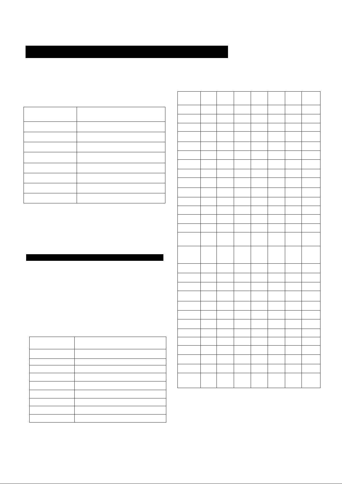
Specifications
Audio Power Specifications
POWER OUTPUT AND TOTAL HARMONIC
DISTORTION
With 8-ohm load, both channels driven,
from 20 - 20,000 Hz, rated 100 watts per
channel minimum RMS power, with no
more than 0.1 % total harmonic distortion
from 250 miliiwatts to rated output.
(U.S. A. modei oniy)
Amplifier section
Continuous RMS power output (8 ohms, at 20 Hz - 20 kHz less than
0.1 % total harmonic distortion) (FRONT)
STR-D911:110W+ now
STR-D711:110W+ 110W
Surround mode
Surround mode (8ohms at 1 kHz. THD 0.9 %)
STR-D711
80W/ch
80 W
20W
FRONT
CENTER*
REAR
STR-D911
80W/ch
80W
25 W
* (only in theDOLBY SUR and THEATER modes)
Other Specifications
Dynamic power output
Harmonic distortion at rated
Frequency response
Inputs
Sensitivity Impedance
PHONO
(MM)
DAT. CD
VIDEO 1.2.
3*
TAPE 1.2
Outputs
REC OUT VIDEO 1
(AUDIO) OUT
HEADPHONES Accepts low and high impedance
MUTING
DBFB
TONE
2.5 mV 50 kilohms
250 mV 50 kilohms
150 W + 150 W (8 ohms)
200 W + 200 W (4 ohms)
output
Less than 0.1 %
PHONO; RIAA equalization curve
±0.5dB
CD. DAT. TAPE 1.2. VIDEO 1.2.3*;
10 Hz-50 kHz :“dB
Voltage 250 mV
Impedance 10 kilohms
headphones
-20 dB
+10 dB at 70 Hz
±8 dB at 100 Hz and 10 kHz
• STR-D911 only
S/N (weighting
network, input level)
74 dB
72 dB** (A. 2.5 mV)
95 dB
80 dB** (A. 250 mV)
•STR-D911 only
•* 78IHF
32
Page 33

FM tuner section
Tuning range
Antenna terminals
Sensitivity
Usable sensitivity
S/N
Harmonic distortion at 1 kHz Mono: 0.3 %
Separation
Frequency response
Selectivity
AM tuner section
Tuning range
Antenna
Usable sensitivity
S/N
Harmonic distortion
Selectivity
87.5-108.0 MHz
300 ohms, balanced
75 ohms, unbalanced
Australian model (at 46 dB):
18.3 dBf, 4.5 nV (mono)
38.3 dBf. 45 |iV (stereo)
Other models (at 50 dB);
18.3 dBf. 4.5 nV (mono)
38.3 dBf. 45 nV (stereo)
11.2dBf.2nV(IHF)
Mono: 76 dB
Stereo; 70 dB
Stereo: 0.5 %
45 dB at 1kHz „
30 Hz-15 kHz 2
60 dB at 400 kHz
530 -1710 kHz (with 10 kHz interval)
531 -1710 kHz (with 9 kHz interval)
531 - 1602 KHz (Australian model)
Loop antenna
50 dB/m (at 1.000 kHz or 999 kHz)
54 dB (at50mV/m)
0.5% (50 mV/m. 400 Hz)
35 dB (9 kHz). 40 dB (10 kHz)
dB
Video section
Inputs
Outputs
General
System
Power requirements
Power consumption (in standby condition: 5W)
AC outlets
Dimensions
Mass
STR-D911: VIDEO 1.2.3:
1 Vp-p 75 ohms
STR-D711: VIDEO 1.2:
1 Vp-p 75 ohms
VIDEO 1. MONITOR: 1 Vp-p 75 ohms
Tuner section: PLL quartz-locked
digital synthesizer system
Preamplifier section: Low-noise NF
type equalizer
Power amplifier section: Pure
complimentary SEPP
120 VAC. 60 Hz (USA. Canadian model)
240 VAC. 50 Hz (Australian model)
STR-D911 ;USA model: 195 W
Canada model; 280 VA
Australian model: 220 W
STR-D711 :USA model: 195 W
Canada model: 280 VA
U.S.A. and Canadian models:
Two switched, total 120 W
Australian model;
One switched. 100 W
430 X 148 X 355 mm
(17x5 7gXl4inches)
STR-D911:10.1 kg (22 lb 4 oz)
STR-D711:10.0 kg (22 lb 1 oz)
Supplied accessories
Design and specifications are subject to change without notice.
Note
This appliance conforms with EEC Directive 87/308/EEC regarding
interference suppression.
FM wire antenna (1)
AM loop antenna (1)
Remote commander (1)
Sony Batteries SUM-3(NS) (2)
33
Page 34

Quick Reference
When operate the unit consulting this Quick Reference, make sure that the unit and
the various audioArideo equipment are properly connected.
Directly tuning in an
Presetting stations
Ex. Tuning in the
POWER
___
^
o
I powerI -
V T5
FM station of 102.50 MHz
^ 1 FM/AM 1
15
TUNER
15
-ij-
Tune in a
desired *
staiton
1 “RECT 1
0
"4 1 1 — 1 1 Ti
n f ^
15151515
«102. BOMHi
Select
memory
I
MEMORY
■ K
page
Select
channel No.
n -—I ~
1
1 "7T -— 1
b
Tuning in a preset
station
Method A: Direct tuning
Method B: Scan tuning
POWER
n 15 b
£<S>
TUNER
TUNER
Select
memory
page
r -• r~n
Select
channel No.
PRESET TUNING
34
Page 35

INDEX
Labeling the preset
stations
Selecting a station
among the preset
stations in the Index
r^,
____________
POWER I I TUNER
n Q
Tune in a
TUNER
15
1 DISPLAY 1
Select the station memorized
under the same index name.
PRESET TUNING
INDEX SELECT/TUNING
b
J
b
35
Page 36

Quick Reference
Adjusting the TONE
controls
Adjusting the
surround setting
Calling up the SOUND
FIELD setting
Select the
desired
SOUND FIELD
program.
Select the
desired
SOUND FIELD
program.
Press the desired
SOUND FIELD program.
hH—1- 1
CURSOR MODE-
CURSOR MODE-
TONE
\ »
SUR
Select BASS or
TREBLE.
bS -
b
Select the
mode.
b
LEVEL
Q
LEVEL
Bfl
<□
Unking the SOUND
RELD memory to
preset stations or
program source
b
Tune in a station or select
the program source to be
linked with sound field
data.
1 »«FF 1
LINK
b
Select the desired
SOUND FIELD program.
b
Sony Corporation Printed in Malaysia
 Loading...