

Page 1

SONY
3-750-436-41 (2)
FM Stemo/FM-AM
Receiver
operating Instructions
STR-AV1010
STR-AV910
STR-AV710
® 1989 by Sony Corporation
Page 2
OWNER’S RECORD
For the customers in Canada
The model and serial numbers are located at the rear.
Record the serial number in the space provided below.
Refer to these numbers whenever you call upon your Sony
dealer regarding this product.
Model No..
Serial No.
WARNING
To prevent fire or shock hazard, do not ex
pose the unit to rain or moisture.
- CAUTION:--------------------------------------------------------------
TO PREVENT ELECTRIC SHOCK, DO NOT USE THIS
POLARIZED AC PLUG WITH AN EXTENSION CORD.
RECEPTACLE OR OTHER OUTLET UNLESS THE
BLADES CAN BE FULLY INSERTED TO PREVENT
BLADE EXPOSURE.
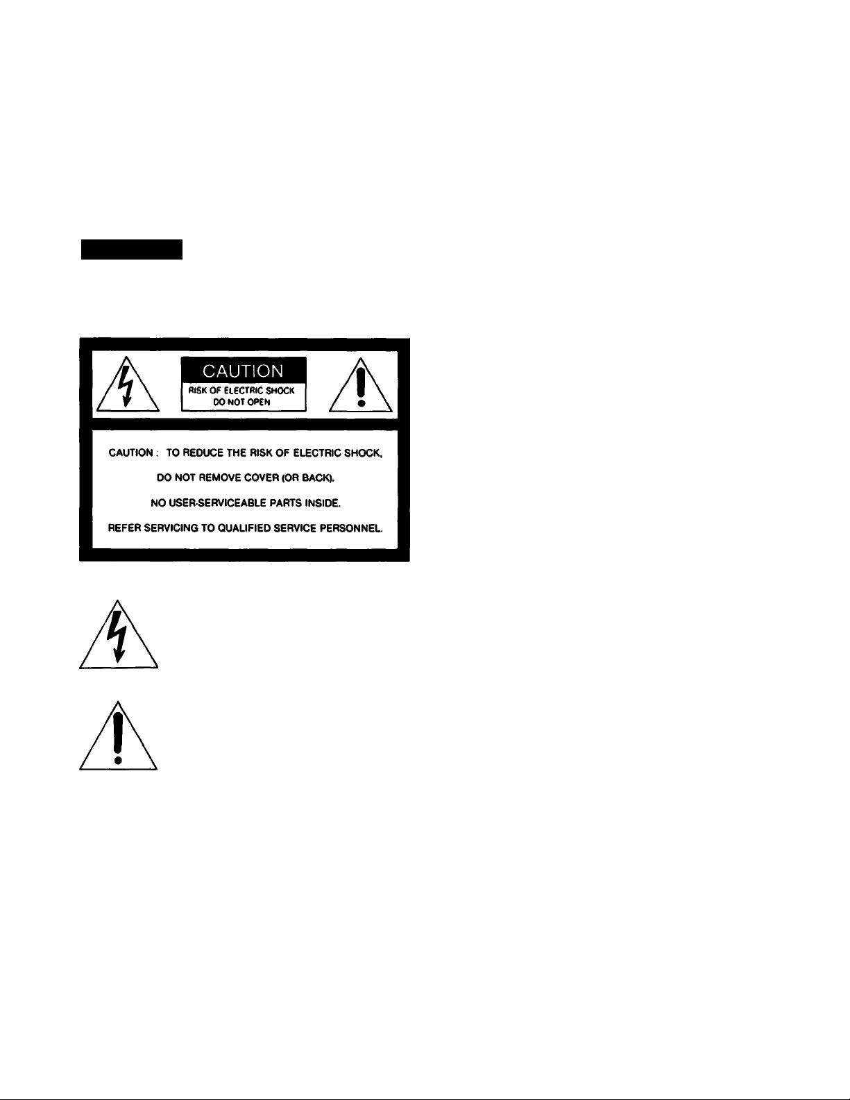
This symbol is intended to alert the
user to the presence of uninsulated
“dangerous voltage” within the prod
uct’s enclosure that may be of suffi
cient magnitude to constitute a risk of
electric shock to persons.
This symbol is intended to alert the
user to the presence of important
operating and maintenance (servicing)
instructions in the literature accompa
nying the appliance.
|— Note to CATV system installer-------------------------------------
This reminder is provided to call the CATV system
installer’s attention to Article 820-22 of the NEC that
provides guidelines for proper grounding and, in
particular, specifies that the cable ground shall be
connected to the grounding system of the building, as
close to the point of cable entry as practical.
Page 3

Table of Contents
Outline
______________________________________________________________________
Precautions___________________________________________________________________ 4
lns|tallation___________________________________________________________________ 5
Cohnections__________________________________________________________________ 6
Notes on connections
Overall connection diagram
Connecting the FM antenna
Connecting the AM antenna
Getting Started
Parts identification
Using the remote commander_____________________________________________________16
AuUio adjustment---------------------------------------------------------------------------------------------------------------- 18
Receiving radio broadcast programs
Using the graphic equalizer.____________________________________________________________ 24
Using Your Receiver
Listening to program sources other than radio broadcasts
Recording on an audio tape or DAT
Video operations____________________________________________________________________ 30
Adding new sound on a video tape during video editing
Connecting a speaker system___________________________________________________ 8
Connecting a VCR, monitor TV, etc. equipped with the connectors for
component video signal of the luminance and the chrominance________________________ 8
Connecting the remote control system
Connecting the AC power------------------------------------------------------------------------------------------ 9
Front panel
Programmable System Commander RM-P201 (supplied with the STR-AV1010)
Remote commander RM-U100 (supplied with the STR-AV9KV710)
Direct tuning
Auto-tuning________________________________________________________________ 20
Presetting stations without index name—Station preset
Presetting stations with index name—Index input____________________________________21
Tuning in preset stations—Preset tuning___________________________________________22
Index tuning________________________________________________________________23
Creating a new equalization curve________________________________________________24
Memorizing a new equalization curve
Enjoying surround sound______________________________________________________26
Receiving FM simulcast TV programs_____________________________________________28
Recording a TV program on a video tape___________________________________________30
Video tape editing---------------------------------------------------------------------------------------------------31
________________________________________________________
____________________________________________________
____________________________________________________
____________________________________________________
____________________________________________
_____________________________________________________________
________________________________________________________________
______________
_______________________
_____________________________________________________
_______________________________________________________________
_______________________________
_____________________________________________
_____________________________________
______________________________________________________
_______________________________________
4
6
6
7
7
9
10
10
12
14
19
19
20
25
28
29
32
Getting into the
Detaiis
Troubleshooting
Quick Reference
Specifications
Troubleshooting guide________________________________________________________________ 34
Quick reference_____________________________________________________________________ 36
____ _
.33
Page 4

Outline
The STR-AV1010rai(V710 is a FM Stereo/FM-AM receiver and audio/video control center.
You can enjoy various audio/video program sources with this unit.
TV/VIDEO Programs
• You can enjoy TV or CATV programs with FM
simulcast.
• Sounds from various audio program sources can be
added on video tapes during editing.
Tuner
• Precise tuning is ensured by a quartz lock digital
synthesizer.
• Station Index system allows you to tune into a station
quickly.
Electronic graphic equalizer and Music Index system
• You can enjoy audio program sources with an appropriate
equalization curve.
• Memorization of equaiization curve is possible as well as
curve adjustment.
• Combined use of the graphic equalizer and the preset
EQ Link system allows you to very quickly tune in a
preset broadcast station and immediately enjoy the
sound with the memorized equalization curve.
Remote control
•The supplied remote commander allows you to remotely
control both the unit and the equipment connected to the
unit.
• The commander supplied with the STR-AV1010 can team
various functions of other remote commanders of the
infrared type.
Sunound sound system
This unit incorporates all of five types of surround effect.
• nPiPowBuiiwouiiiDi ♦ —expands sound just like listening
to it in a movie theater.
• Hall Surround—provides reverberation effect that is
produced in a large concert hall.
• Live surround—provides the sound effect just like listening
a real live performance.
• Stadium surround—provides the sound effect just like
being in a stadium.
•Simulated Surround—gives the feeling of width and
thickness to monaural sound of old movie program, etc.
• Manufactured under license from Dolby Laboratories Licensing Corporation.
Additionally licensed under one or more of the following patents; U.S numbers
3.632S86. ^745,792, and 3,969,590; Canadian numbers 1.004,903 and 1C37S77.
"DOLBY" and the double-D symbol QQ are trademarfrs of Dolby Laboratories
Licensing Corporation.
Display
• The frequency of each tuned-in broadcast station is
displayed.
• The current selection/operation is displayed to clearly
indicate what is taking place.
Precautions
On safety
• Operate the unit only on 120 V AC, 60 Hz.
• Should any solid object or liquid fall Into the cabinet,
unplug the unit and have it checked by qualified personnel
before operating it any further.
• Unplug the unit from the wall outlet if it is not to be used for
an extended period of time. To disconnect the cord, pull it
out by grasping the plug. Never pull the cord itself.
• One blade of the plug is wider than the other for the
purpose of safety and will f it into the power outlet only one
way. If you are unable to insert the plug fully into the outlet,
contact your dealer.
On operation
Before making program source connections, be sure to
unplug the unit.
On cleaning the cabinet
Clean the cabinet, panel and controls with a soft cloth
slightly moistened with mild detergent solution. Do not use
any type of abrasive pad, scouring powder, or solvent such
as alcohol or benzine.
For the customers in U.SA
For detailed safety precautions, see the “IMPORTANT
SAFEGUARDS” leaflet.
If you have any question or problem concerning your unit,
please consult your nearest Sony dealer.
Page 5
Installation
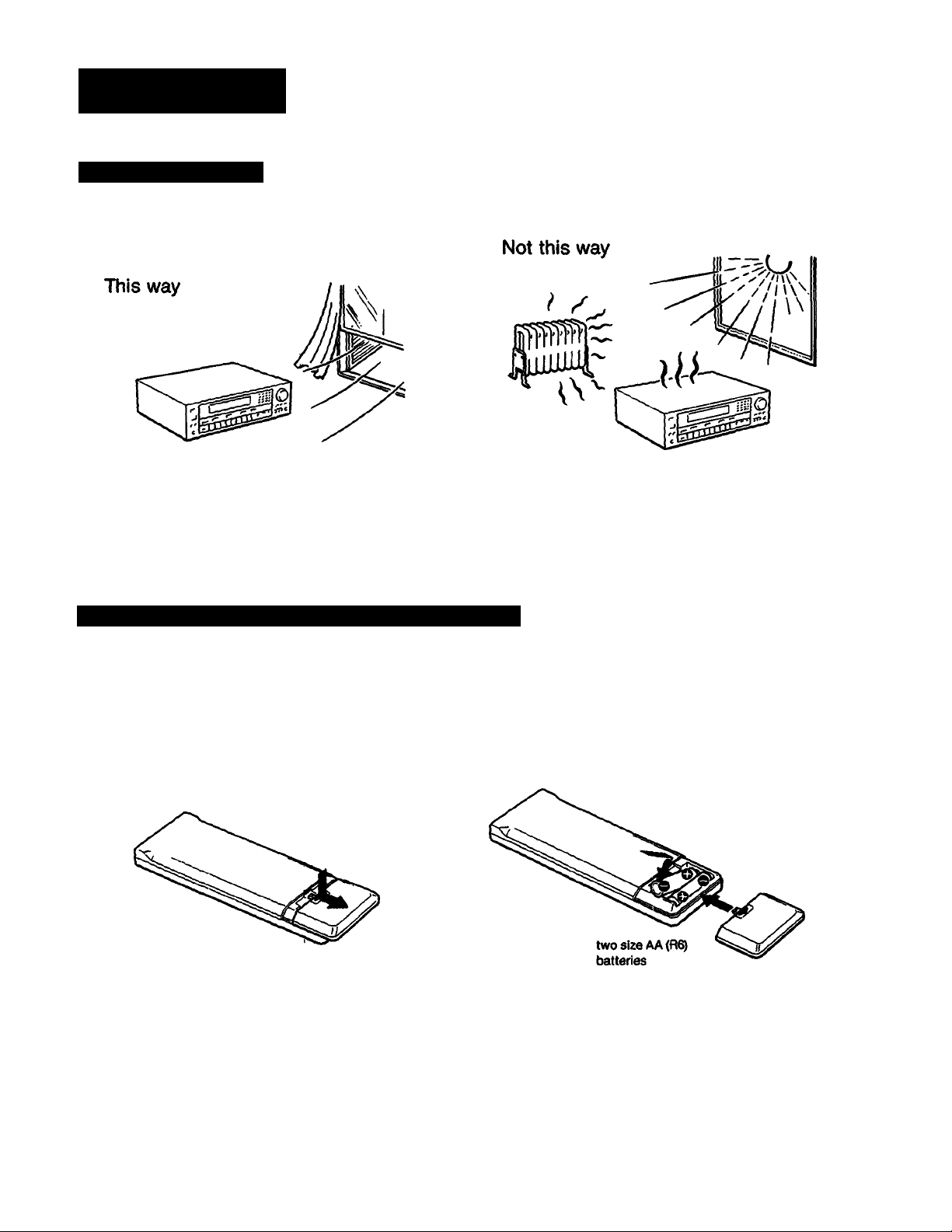
Notes on Installation
Place the unit in a location with adequate air circulation to
prevent intenal heat build-up in the unit.
Do not install this unit:
• near heat sources such as radiators or air ducts.
• in a place subject to direct sunlight, excessive dust, mechanical vibration or shock.
Do not place anything on top of the cabinet. The top ventilation holes must be unobstructed for the proper operation of the
unit and to prolong the life of its components.
Loading the Batteries into the Remote Commander
RM-P201 and RM'UlOO Remote Commander
1
Do not throw away the carton and packing material.
It will be an ideal container when transporting the unit for repair
work, etc.
To avoid damage caused by battery leakage and corrosion
When the commander will not be used for a long time, remove the
batteries.
Battery life
Normal operation can be expected about a half year using Sony
SUM-3 (NS), and a year using Sony AM-3 (NW) alkaline batteries.
When the batteries are run down, the remote commander will not
operate the unit, tn this case, replace the batteries with new ones.
Page 6
Connections
Notes on Connections
• Do not connect the power cord to an AC outlet nor press
the SYSTEM POWER switch before accomplishing all other
connections.
• The cable connectors should be fully inserted into the
jacks. Loose connection may cause hum and noise.
• Cord plugs and jacks are color coded. Red plugs and jacks
are for right channel (R) and white ones for left channel (L).
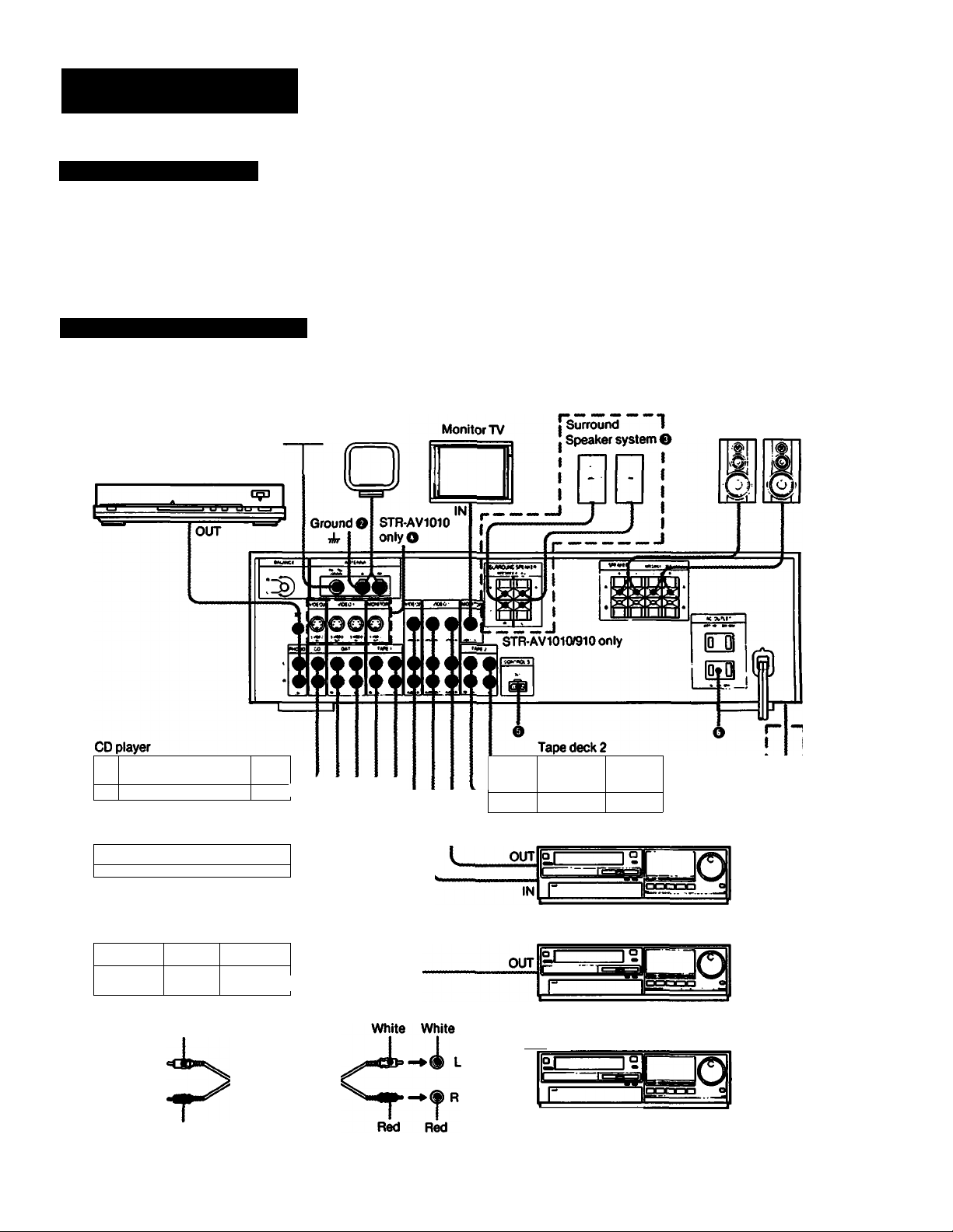
Overall Connection Diagram
The numbers placed in a circle • correspond to those of the individual connecting diagrams given on the following
pages.
FM AM
antenna O antenna O
Turntable system
Speaker
system O
o
o
aOBOCBa n 1 }~i 1
••
DAT deck
o|-l
-------
• a
' ■
Tape deck 1
1 1
1
__
1
L(
R I
^°L
L
1
______
lol 1 1—loool «
OOO
White
Red
iii
OUT
OOO
^diiiO
IN
• •
OUT
IN
1 .1
• • te O
OUT
1—5"
AUDIO CABLE: RK-C74
. OUT
a|
_______
IN
VCR1
VCR 2
To VIDEOS INPUT I
I
-------------------------------------------------------------
I VCR
1
OOO 1
I
I
I ____________
f STR-AV1010only
L.
*
OUT
Page 7
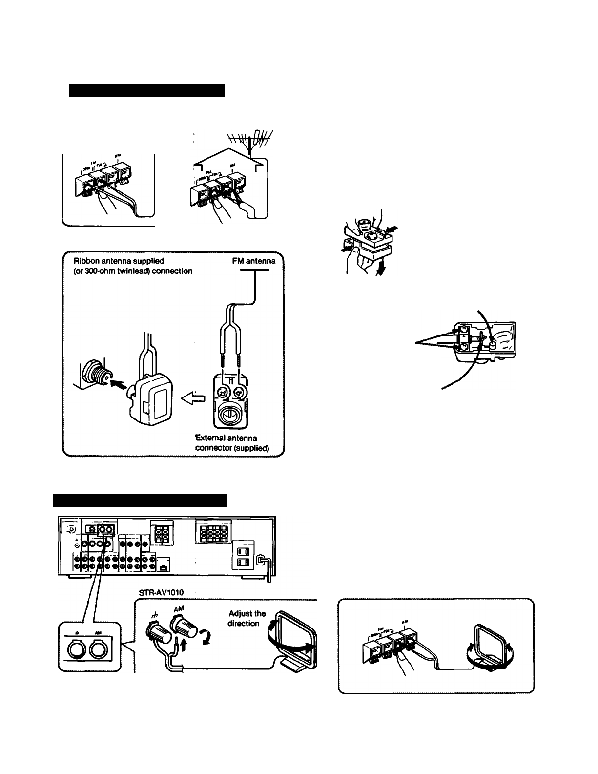
Connecting the FM Antenna
STR-AV910/710
For normal use
For higher quality sound
75<ohm coaxial cable connection
A 7S^hm coaxial cable is free from external Interference,
reduces noise pickup, and is the ideal transmission line for
most FM installations. 3C-2V cable is recommended.
Connect the 75^hm coaxial cable to the supplied antenna
connector and connect it to the FM antenna connector.
O Open the lid. 9 Strip the cable.
STRAV1010
0 Connecting the AM Antenna
8{“/n)10(“/j2)mm(in.)
O Bemove the ring.
(Keep it in the projection on the lid.)
o Loosen the screws
and insert the cable
0
Coil the center conductor
O Snap the cover into place.
For areas «with difficult AM reception
In areas with troubled reception, connect a 6- to 15-meter
(20- to SO-foot) insulated wire to the AM antenna terminal.
Extend this out of doors if possible, keeping the geater
portion horizontal.
(There Is no need to disconnect the supplied antenna)
STR-AV910f710
Supplied AM antenna
To prevent hum, connect the ground wire to ANTENNA ground terminal (j,).
When an outdoor antenna is installed, be sure to connect the ground wire for lightning protection.
Page 8
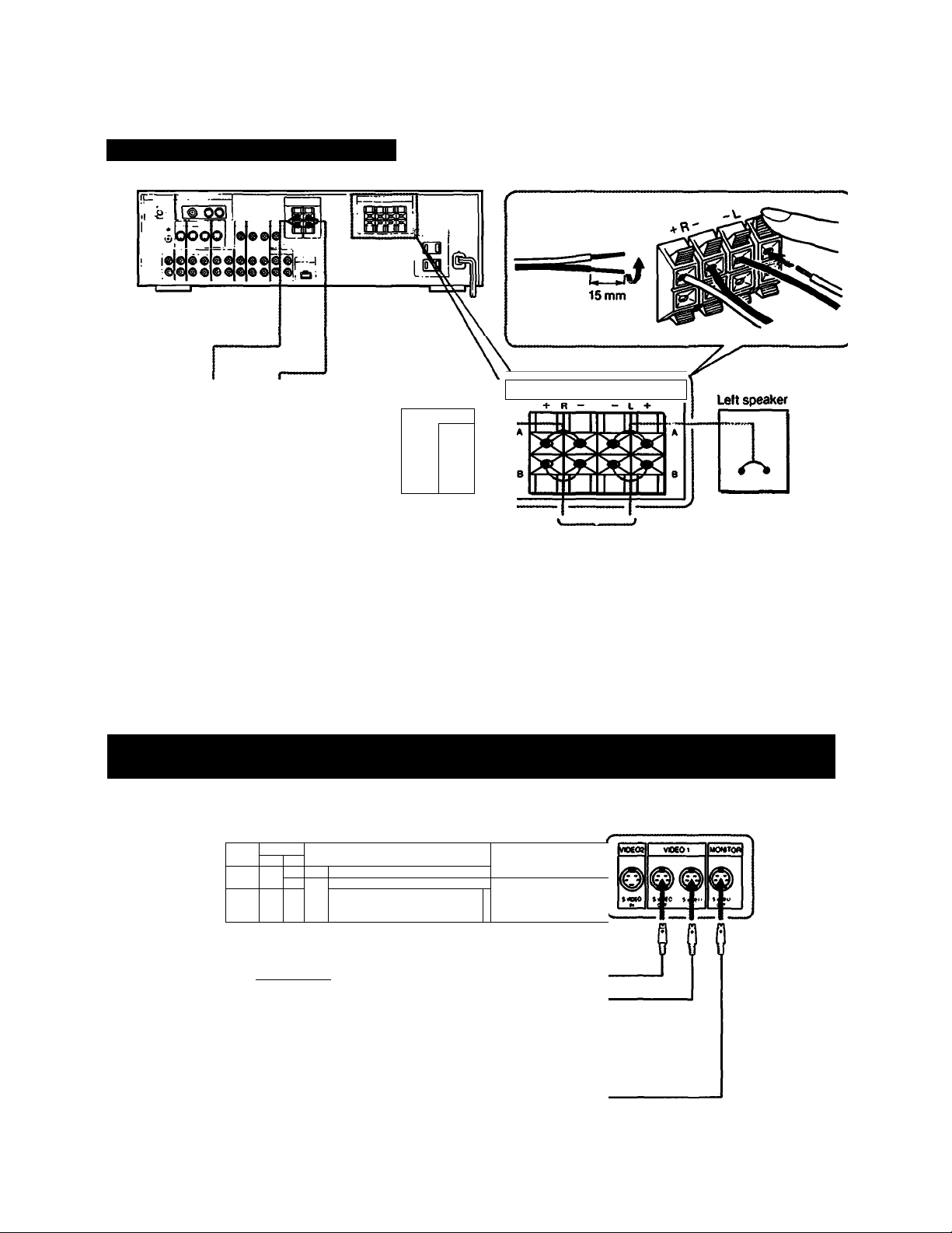
O Connecting a Speaker System
A
Surround speaker system
(for STR-AV1010/910 only)
A
Right speaker
SPEAKER
to the second speaker system
iNFCOMCf 0K8
Speaker impedance and power capability
This receiver is designed to work best with speakers having
nominal impedance from 8 to 16 ohms, at rated 120 watts (STRAV1O10), 100 watts (STRAV910) or 55 watts (STR-AV710) minimum
RMS per channel with an 8ohm load from 20 - 20,000 Hz.
For surround speakers, connect speakers having nominal
inpedance from 8 to 16 ohms and rated over 20 watts RMS.
(STR-AV1010/910only)
O Connecting a VCR, Monitor TV, etc. Equipped with the Connectors for Component
Video Signal of the Luminance and the Chrominance
This connection is possible only with the STR-AV1010.
STR-AV1010
8
Iv V
vl
0 U
3 00
eoe
D»«
é|<
i|e«
F- ,=¿11 in
"1
...............................
Monitor TV
---------------------
VCR
to S VIDEO IN
ail^
to S VIDEO IN
to S VIDEO OUT
YC-15EV
Page 9
0 Connecting the Remote Control System
To control the equipment connected to the receiver with the remote commander, connect the CONTROL S OUT connector
and the CONTROL S IN connector of each equipment as illustrated below.
Example of audio connection
CONTROLS
AUDIO
connection
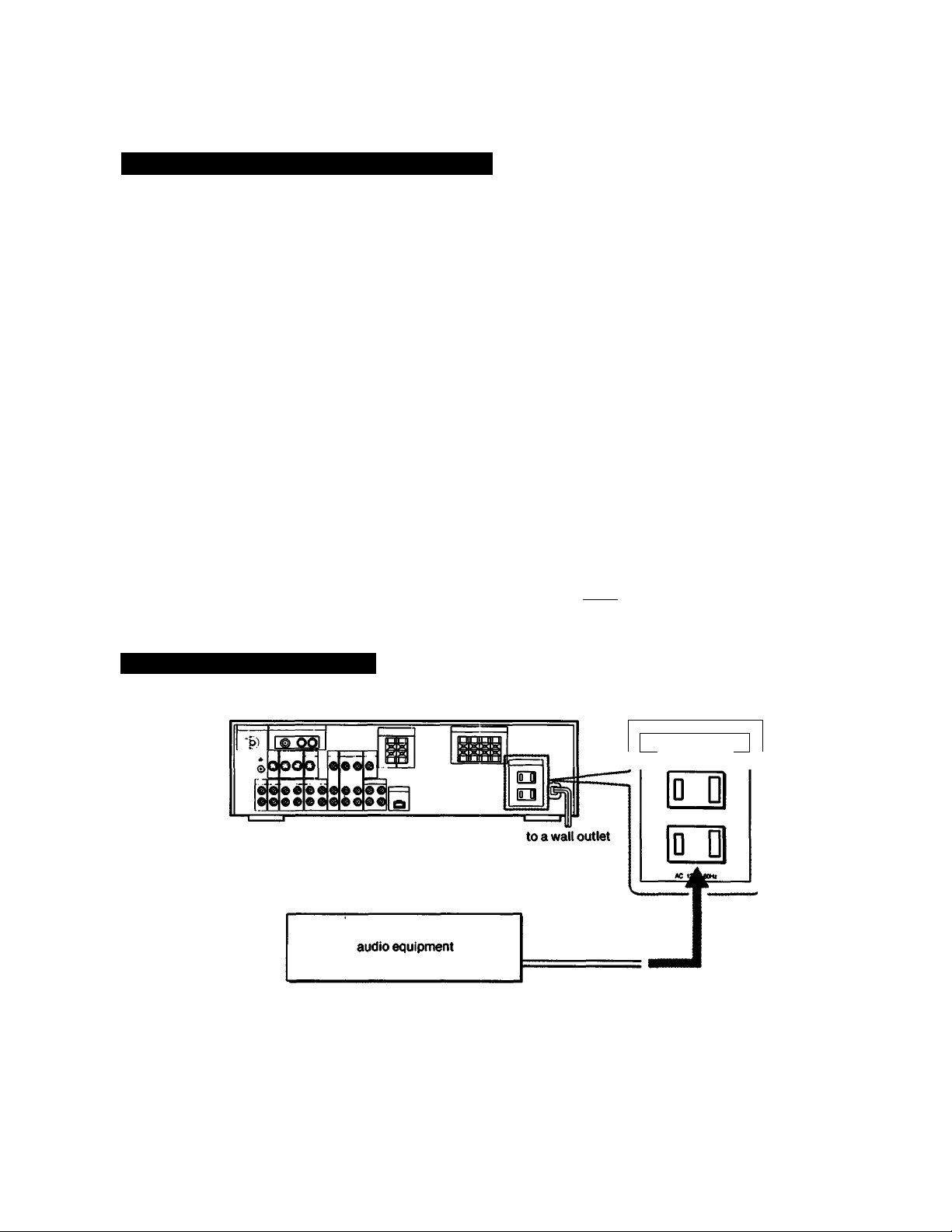
O Connecting the AC Power
Tape deck
IN
OUT
to the AC outlet of
the receiver
E
Turntable system
IN
OUT
IN
OUT
CD player
Receiver
H
...........
to the AC outlet of
the receiver
to a wall outlet
a wall outlet
» to
r
AC OUTLET
SMTCHEO lOM imi
\
Caution
Be careful that the total power consumption of each
equipment connected to the outlets on the receiver does not
exceed 100 watts.
Do not connect electrical home appliance such as an electric
iron, fan, TV, or other high-wattage equipment to these outlets,
Page 10
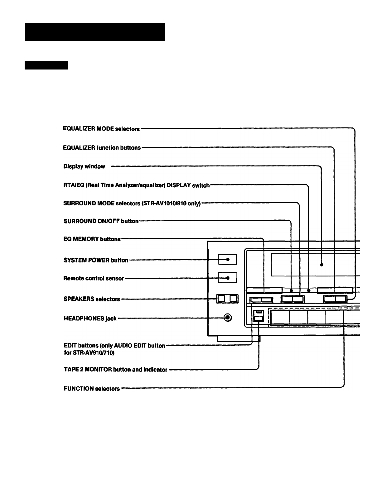
Parts Identification
Front Panel
PRESET EQ LINK ON/OFF button-
10
Page 11
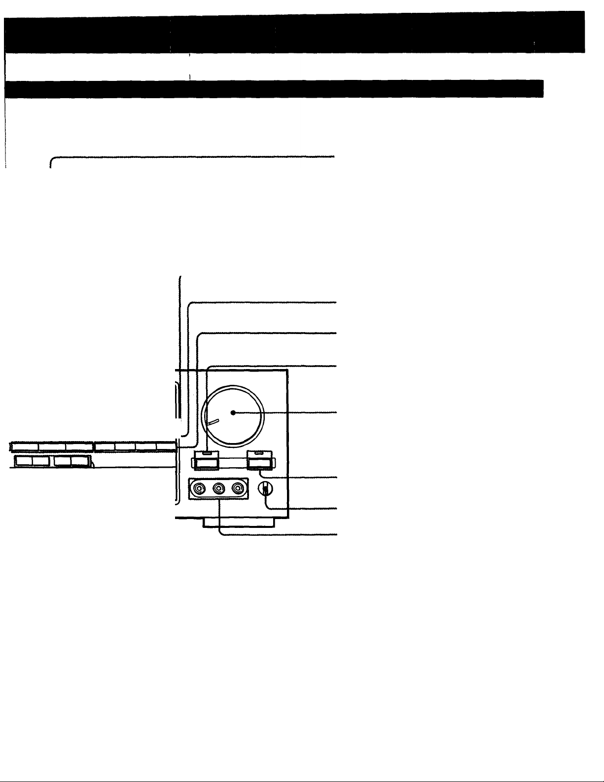
Tuner function buttons
■MEMORY button
•Numeric buttons
• EQ PGM SET (equalizer program set) button
DIRECT TUNING button
SHIFT button
CURSOR MODE selection buttons
DBFS (Dynamic Bass Feed Back)
button and indicator
CDac
□ac
1
STR'AV910/710
VOLUME control knob
MUTING button and indicator
BALANCE control
VIDEOS INPUT jacks
(for STRAV1010 only)
'CURSOR MODE operation buttons
-TUNING buttons (PRESET/INDEX)
11
Page 12
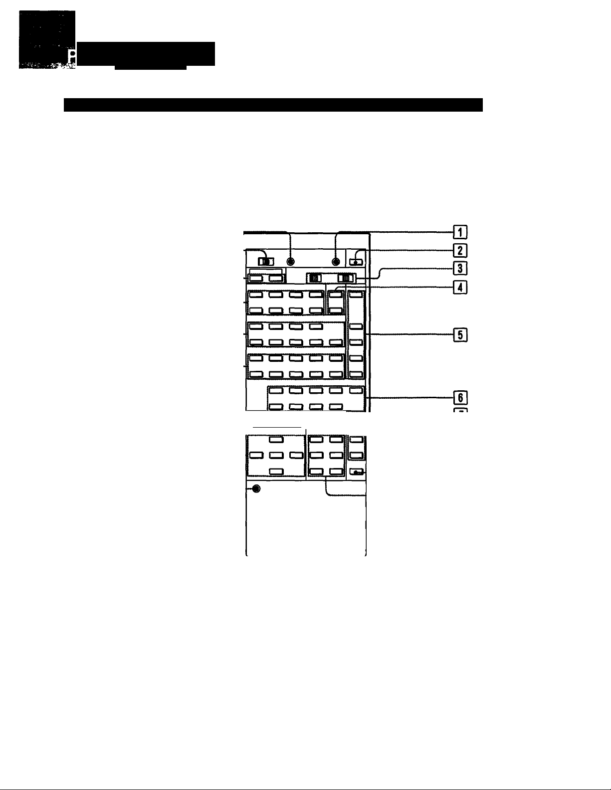
arts (dentification
Programmable System Commander RM-P201 (supplied with the STR-AV1010)
The Programmable System Commander RM-P201 supplied with the STR-AV1010 can learn various functions of other remote
commanders emitting infrared rays.
'"WBeBkii#»»'«.».
When it is set to SONY STD (Sony Standard) by the mode selector, its buttons can be used to perform the functions below.
n-
Hl-
ISl-
O-
Bzl-
IS-
H-
■la'g olia^
12
Page 13

dl PROGRAM CLEAR button
m POWER button
Turns on/off the receiver.
d] ÖECK and VTR selectors
DECK A, B; Selects deck A or B.
VTR 1,2,3: Selects VCR 1,2 or 3.
1: BetamaxVCRs
2:8 mm VCRs
3:VHSVCRs
[U PHONO buttons
START: Starts record play.
STOR Stops record play.
[D TV operation buttons
TVA/IDEO: Selects the Input signal to the TV set, either a
TV signal or VCR programs.
VOL (volume) +/- buttons
CH (channel) +!- buttons
m FUNCTION selectors
Note
DIGITAL button does not function for STR-AV1010.
m SURROUND buttons
ON/OFF: Turns on/off the surround mode.
MODE: Selects the surround mode.
m DBFB/DDS ON/OFF switch
Turns on/off DBFB (Dynamic Bass Feed Back)
[|] VOL (volume) control buttons
H MUTING button
Ql] TUNER operation buttons
INDEX: Preset station index select |buttons
+/-: Selects a next/previous preset station under
the same index.
SELECT: Index select button
PRESET: Preset station select buttons
+/-: Selects a higher/lower preset channel
number.
EQ LINK: Turns on/off the equalizer link.
QH CD player operation buttons
Starts play.
■: Stops play.
AMS (Automatic Music Sensor)
PGM: Program play
SHUFFLE: Shuffle play
CONTINUE: Continuous play
DISC SKIR Disc skip
QH TAPE deck operation buttons
Reverse fast winding
Reverse play
Forward play
Fonward fast winding
■: Stop
II: Pause
•: Recording (While you press #, press REV for reverse
recording or FWD for forward recording.)
IE VTR operation buttons
Rewind
►: Play
Fast forward
■: Stop
II: Pause
•: Recording buttons (Press both buttons for recording.)
ANT TV/VTR: Selects the output signal from the antenna
terminal from the VCR, either TV or VCR.
CH +/-: Channel select buttons
mi EQUALIZER operation buttons
ON/OFF: Turns on/off the equalizer.
MODE Selects the equalizer mode (A through F).
BAND: Selects the equalizer band.
(This button does not function for STR-AV101Q.
01] CURSOR MODE operation buttons
H RESET button
Notes
•When the CONTROL S OUT connector is connected to the
CONTROL S IN connector of each equipment, you can
control the connected equipment using this remote
commander.
QH LEARN indicator
Qll Mode selector
SONY STD: To operate the commander on Sony standard.
USER STD: To use the learned functions.
LEARN: To perform learning function.
IE TV and VTR POWER buttons
TV: Turns on/off the TV.
VTR: Turns on/off the VCR.
13
Page 14

Parts Identification
Remote Commander RM-U100 (supplied with STR-AV910A710)
n-
t
-m
m
O-
03
lcz> al
i=]
-m
{a
m
a.
fa-Ol
OQ
-
CD CD
CD
5^
(U CB
-(U
■m
m
m
■a
a
14
Page 15

(H POWER button
Turns on/off the receiver.
[T| DECK and VTR selectors
DECK A, B: Selects deck A or B.
VTR 1,2,3: Selects VCR 1,2 or 3.
1; Betamax VCRs
2:8 mm VCRs
3: VMS VCRs
(HI TUNER operation buttons
INDE)C Preset station index select buttons
+I-: Selects a next/previous preset station under
the same index.
SELECCT: Index select button
PRESET; Preset station select buttons
+/-: Selects a higher lower preset channel
number.
EQ LINK: Turns on/off the equalizer link.
[T| CD player operation buttons
►:Play
■: Stop
AMS (Automatic Music Sensor)
PGM; Program play
SHUFFLE Shuffle play
CONTINUE (Continuous play
DISC SKIR Disc skip
Q] TV operation buttons
TVA/IDEO: Selects the input signal to the TV set, either a
TV signal or VCR programs.
VOL (volume)+/-buttons
CH (channel) +/- buttons
d] TAPE deck operation buttons
<«; Reverse fast winding
Reverse play
Forward play
Forward fast winding
■: Stop
II: Pause
O'. Record muting
•; Recording (While you press •, press M or ^.)
[S VTR operation buttons
Rewind
►: Play
Fast forward
■'.Stop
II; Pause
•: Recording (While you press •. press ►)
ANT TVAfTR; Selects the output signal from the antenna
terminal from the VCR, either TV dr VCR.
CH +/-: Channel select buttons
[gl TV and VTR POWER buttons
TV: Turns on/off TV.
VTR: Turns on/off VCR.
(ni PHONO buttons
START: Starts record play.
STOR Stops record play.
QD FUNCTION selectors
(gl EQUALIZER operation buttons
ON/OFF: Turns on/off the equalizer.
MODE Selects the equalizer mode (A through F).
|]|] CURSOR MODE operation buttons
Notes
• When the CONTROL S OUT connector is connected to the
(DONTROL S IN connector of each equipment, you can control
the connected equipment using this remote commander.
Note on the • (recording) button under [T)VTR operation buttons
If your VCR is of such type as pressing • puts it in REC PAUSE
mode, first press • on this commander and then ll.
d] SURROUND buttons
ON/OFF; Turns on/off the surround mode.
MODE: Selects the surround mode (except for STR*
AV71Q).
d] DBFB button
Turns on/off the DBFB (Dynamic Bass Feed Bacl^.
[T| VOL (volume) control buttons
H MUTING button
15
Page 16

Using the Remote Commander
• When you manipulate a switch or button on the commander, be sure to point the head of the commander toward the remote
control sensor on the front of the receiver.
• If there is an obstacle between the receiver and the head of the commander, the receiver may not be controlled remotely.
Programming Signals of Other Audio/Video Equipment with Programmable System
Commander RM-P201
16
Page 17

After programming
Be sure to test if the equipment really works with the programmed
signals.
If the LEARN indicator flashes or does not go out In step 2> r, i
The memory capacity has become fuii. This occurs when other
signals stronger than the remote-control signals have been stored
because the signals were programmed in a noisy environment or
the remote commanders were placed too for apart from each
other.
Clear all the signals following the procedure on the right and
program again from the begining under the proper conditions.
Notes on programming
• Remote-control signals of equipment of manufactures other
than Sony can be programmed only when they are compatible
with the infrated wireless remote control system. Since the
programmable commander can “learn" only the signals output
from another remote commander, it cannot control equipment
that do not use a remote commander. Also, note that there are
some special remote-control signals that cannot be
programmed.
• Do not attempt to use the programmable commander with an air
conditioner or other household appliances.
To program a new signal onto a previously programmed
button
Follow the programming procedure.
The previously programmed signal is cleared and replaced by
the new signal.
To clear all programmed signals
1 Set the mode selector to LEARN.
2 Press and hold any button of the programmable area until
the LEARN indicator lights up.
3 Press PROGRAM CLEAR until the LEARN indicator flashes
and goes off.
It is not possible to clear the programmed content of just one
button.
To program a signal onto the • REC button in the TAPE or
VTR section
It is not possible to operate any equipment with only the •
REC button. To program a signal under the • REC button,
press and hold the following buttons at the same time in step
2-1.
TAPE
VTR
Controlling Equipment
By switching the mode seiector as shown below, a single button alternately controls Sony equipment and another
manufacturer equipment.
To control Sony equipment.
SONY
STD
□
tn—i
____________I__I__
When Sony equipment cannot be remote-controlled
Program the signal in the same way as for equipment from other
manufacturers. In this case, even with Sony equipment, set the
mode selector to USER STD.
Battery life
Normal operation can be expected about a half year using Sony
SUM-3 (NS), and a year using Sony AM-3 (NW) alkaline batteries.
If the LEARN indicator does not light when a button is pressed,
the batteries are almost exhausted.
When the batteries are exhausted, the remote commander can no
longer operate the unit or programming becomes impossible.
W this happens, replace both batteries with new ones. We strongly
recommend the use of alkaline batteries.
□ o o 1=1
ID nn
If no signal has been programmed
The programmable commander can control Sony equipment even
when the mode selector is set to USER STD.
If the equipment works incorrectly
Press RESET and start again. The programmed contents of the
buttons are not cleared by pressing RESET.
To control equipment with
programmed signals
USER STD
17
Page 18

Audio Adjustment
You can enjoy superb sounds using the audio adjustment functions as shown beiow.
Volume Adjustment
Adjust the VOLUME control.
Temporarily reducing the sound to a low level (-20 dB
attenuation)
Press MUTING.
Press again to restore the previous level.
Balance Adjustment
Changing the relative output strength of the right and
left speakers
Adjust BALANCE to correct stereo imaging, when the
speaker position is not symmetricai.
Sound Quality Adjustment
Selecting a factory-preset equalization curve
Press EQUALIZER ON/OFF.
Select a desired equalization mode by pressing the EQUALIZER MODE V or a.
Press EQUALIZER ON/OFF again to turn off the effect.
• EQUALIZER-
0№0FF i
EQUALIZER MODE
VIA I
b
Creating and/or Memorizing a New Equalization Curve
See “Using the Graphic Equalizer," pages 24,25.
o
1
/
-----------
\ VOLUME
MUTING
____
0
LEFT • RIGHT
BALANCE
OFF
manual
► A
e
c
0
E
F
EOMODE
To reinforce the bass sound
Press DBFS (Dynamic Bass Feed Bacl^ to
obtain powerful bass sound at small
output levels.
Indicator lights up.
Press again to turn off the effect.
18
Enjoying the surround sound
Press SURROUND.
Press again to turn off the effect.
SURROUND
Page 19

Receiving Radio Broadcast Programs
Direct Tuning
1 Select the function TUNER. 2 Select FM or AM.
3 Press TUNING DIRECT.
4 Enter the frequency of the desired station by
pressing the appropriate numeric buttons.
The entered frequency is displayed.
Example 1-.FM 102.50 MHz Example2: AM ISSOkHz
Tuning intenrals for direct tuning
FM: 50 kHz interval
AM; 10 kHz interval (changeable to the 9 kHz interval)
Changing the AM tuning intental
The AM tuning inten/al is preset to 10 kHz. To use the
receiver where the frequency allocation system is based
on the 9 kHz interval, make the following adjustments:
1 Turn on the power and tune in any AM station.
2 Press SYSTEM POWER to turn off the receiver.
3 Press again SYSTEM POWER to turn on the receiver
while pressing PRESET TUNING +.
I inpcn I I ! 1Q n
I
I U C .JI U UH2
5 Adjust the volume.
Resetting the AM tuning intetvai
Follow the procedure for changing the AM tuning inten/al.
Caution
When the interval is changed, all preset stations which you
have memorized will be erased. After changing the inten/al,
be sure to newly preset stations. (See “Presetting Stations...,”
pages 20,21.)
I 1
________
i 3 3 U
kHz
When the entered number is not in the receivable frequency
range
The entered digits (up to 5 digits for FM or up to 3 digits for AM)
biink in the frequency display area, and reception does not take
place.
If this condition occurs, press TUNING DIRECT again, and enter
the correct frequency (the frequency range of the receiver is 87.50
to 108.0 MHz for FM, and 530 to 1710 kHz for AM).
Correcting the entered frequency
Repeat Steps 3 to 4 of Direct Tuning.
For entering AM frequencies, you need not enter the last “0”.
However, if you have changed the AM tuning interval to 9 kHz,
enter all the digits.
If you enter a frequency not covered by the tuning interval
The entered value is automatically rounded up or down to the
closest value covered by the tuning interval.
When an FM stereo program is noisy
When the unit receives an FM stereo program, the STEREO
indicator goes on in the display window. If the stereo program is
noisy, press FM MODE to change the mode over to MONO. This
eliminates the stereo effect, but the noise will be greatly reduced.
To return to the stereo mode, press FM MODE again.
19
Page 20

Selecting the signal level of the station to be tuned
You can select “high” or “low” as the FM tuning level by
TUNING LEVEL on CUFISOR MODE
Press A to select high; HIGH displayed in the display
window.
Press V to select low; HIGH display disappears.
HIGH: The frequencies of strong signal stations only will be
tuned.
LOW: The frequencies of all receivable stations will be
tuned.
Replacing a preset station
Preset another station on the number of the station to be
replaced. The previously preset station will be erased.
20
Page 21

Presetting Stations with Index Name—Index Input
You can divide preset stations under Index Names you create (up to 4 digits). If you want to categorize the preset stations by
kinds of music, for example, create indexes such as ROCK, JA^ etc. Also, a EQUALIZATION MODE can be assigned to preset
stations at the same time.
1 Select the function TUNER.
2 Tune in the desired station with Direct. Auto
or Preset Tuning.
3 Select INDEX on the CURSOR MODE.
4 Create a index name.
To select a letter or a number (1 - 4), press A or
V.
To change the position, press < or >.
5 Press EQ PGM SET to assign a equalization
curve.
G Select a equalization mode which you want
to assign to the selected station.
7 Press MEMORY.
The MEMORY indicator appears.
8 Preset SHIFT to select memory page. (A, B
orC)
S Press the numeric button.
10 Repeat Steps 4 to 9 for all other stations you
want to assign a Index Name to.
If you want to assign a station under the same
Index Name, press A or v to skip the steps 3
to 6.
• Pressing CURSOR MODE INDEX twice make
all 4 digits of the Index flash. Then, all
previously memorized Index can be called up
by pressing A or V. This allows you to
change only one digit of a previously
memorized Index to create a Index Name.
To return to the previous mode, press
CURSOR MODE INDEX again.
Each station can be stored under only one Index Name
If you store an already categorized station under any other Index
Name, only the last selected category will be valid.
21
Page 22

Receiving Radio Broadcast Programs
Tuning in Preset Stations—Preset Tuning
Method A
1 Select the function TUNER.
2 Select the desired preset station by the
PRESET TUNING + or - button.
• Each lime you press PRESET TUNING + (or -). a
preset station of next higher (or lower) channel
number is tuned in.
• If you keep pressing+(or -), preset stations are
successively tuned in the increasing (or
decreasing) order of channel number. Release
the button when the desired station is tuned in.
• Scanning of the preset stations takes place
cyclically from AM to FM and vice versa.
Index Tuning
Method B
1 Select the function TUNER.
2 Press SHIFT to select memory page (A, B or C)
3 Press the preset numeric button.
1 Select the function TUNER.
2 Select the Index Name by pressing INDEX
SELECT.
3 Select the desired station by pressing INDEX
TUNING+/-
When you want to tune into a station memorized
under a different Index Name, press INDEX
SELECT as many times until the desired Index
Name appears.
22
Page 23

Listening to Programs with Preset Equalizer Link
1 Select the function TUNER.
2 Press PRESET EQ LINK ON/OFF to put the
unit in the Link On state.
3 Tune into a station by Preset Tuning or index
Tuning.
Equalizer Mode assigned to the Preset station is
iinked and the sound is processed accordingiy.
To listen to the station without any equalization
Press EQUALIZER ON/OFF to set it to off.
Note
Always turn off the EQ Link function by pressing PRESET EQ
LINK ON/OFF button before selecting other program sources from
TUNER function.
23
Page 24

Using the Graphic Equalizer
You can enjoy a music with a different equalization curve than the ones preset at the factory.
Creating a New Equalization Curve
1 Press RTA/EQ.
This switches the display to the equalizer setting.
2 Select CURSOR MODE EQUALIZER.
3 Press the frequency select button (.1 and'?)
for the frequency of which the level you want
to raise or lower.
4 Press the Level J. (or t ) button to raise (or
lower) the level of the selected frequency. (The
arrow points MANUAL)
5 Repeat Steps 3 and 4 for other frequencies
until you obtain the desired equalization curve.
To restore the RTA (real time analyzer) display, press
RTA/EQ.
Adjustable fiequenq/ bands and the effect of level
adjustment (STR-AV1010/910)
63 Hz: Lowering the level will cut the ventilation noise of a
music hall, hum of electronic instruments, boomy bass,
etc.
Raising the level will reinforce the heavy bass part of a
pipe organ or add depth to the bass sound.
150 Hz: Boosting or cutting the normal bass.
400 Hz: Increasing or decreasing the power, spaciousness
and warmth of the sound.
1 kHz: Providing more presence for vocals, and moving the
sound forward or into the background.
Adjustable frequency bands and the effect of level
adjustment (STR-AV7K))
63 Hz: Lowering the level will cut the ventilation noise of a
music hall, hum of electronic instruments, boomy bass,
etc.
Raising the levei wili reinforce the heavy bass part of a
pipe organ or add depth to the bass sound.
250 Hz: Boosting or cutting the normal bass.
1 kHr Providing more presence for vocals, and moving the
sound forward or into the background.
2.4 kHz: Lowering the level will reduce stridency, and raising
will make the base sound brighter.
6 kHz: Increasing or decreasing the brightness of the sound;
for example, raising the level will make the violin sound
siiky smooth.
14 kHz: Changing the generai atmosphere rather than
the sound itseif.
Raising the levei will highlight the delicate quaiity of
instrumental sound, and lowering will reduce highfrequency noise such as the resonant peak of a cartridge,
tape hiss, etc.
3.3 kHz: Lowering the level will reduce stridency, and raising
will make the base sound brighter.
10 kHz: Increasing or decreasing the brightness of the
sound; for example, raising the levei wili make the violin
sound silky smooth.
24
Page 25

Memorizing a New Equalization Curve
You can store a created equalization curve into memory under any EQUALIZE MODE you select. However, note that this
operation will alter the factory-preset equalization cun« or the last memorized one under the selected EQUALIZER
MODE.
1
Create an equalization curve you want to store.
2
Press EQ MEMORY SET. The MEMORY
indicator will light up for a few seconds.
3
Select a equalizer mode under which you want
to store the equalization curve.
4
Press EQ MEMORY WRITE.
To return to the factory preset equalization curve
Select CURSOR MODE SURROUND and turn the
SYSTEM POWER off.
Turn on the SYSTEM POWER while pressing
SURROUND MODE A.
Surround Mode returns to the factory preset also.
To listen to a music with a memorized
equalization curve
Select the desired equalizer mode.
If you have not stored a curve under that MODE, the
factory-preset curve will be called in.
Note
Graphic equalizer and surround do not have any effect on the
program source connected to the TAPE 2 MONiTOR.
To listen to a music without graphic equalizer effect
Press EQUALIZER ON/OFF button to set it to off.
To accurately check the highest input
Press the PEAK HOLD button.
The real time analyzer display will hold the highest input of each
frequency range for several seconds.
25
Page 26
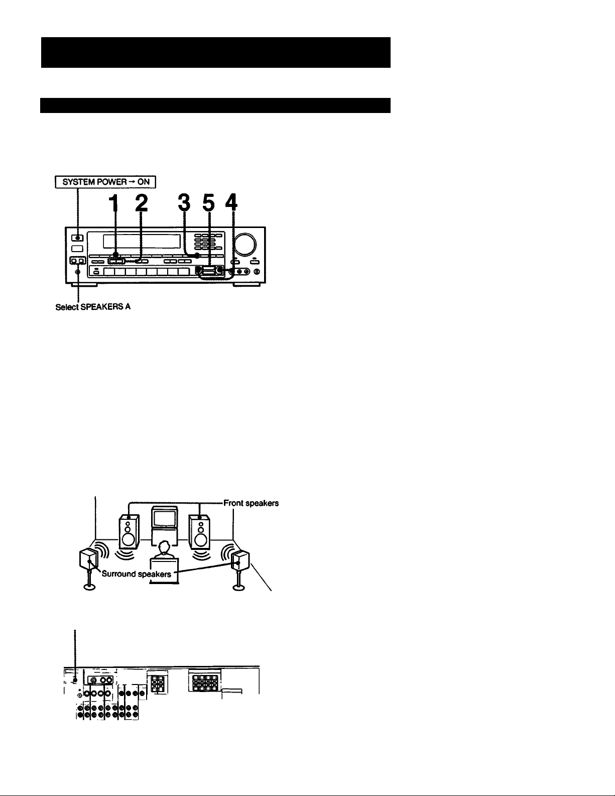
Enjoying the Surround Sound
Listening to the Surround Sound with the STR-AV1010/910
Select SPEAKERS A when listening to the surround sound with rear speakers. SPEAKERS B circuitry does not activate the
rear speakers.
1
Press SURROUND ON/OFF.
2
Select SURROUND MODE.
Select SURROUND on the CURSOR MODE.
3
4
Adjust DELAY TIME S, M or L by pressing <3 or
>. (for DOLBY and SIMULATED only)
Adjust the surround speaker level by pressing
LEVEL J-(+) or
To turn off the surround effect.
Press SURROUND ON/OFF again.
The normal sound without surround effect will
resume.
• Both Level and Delay Time of the surround is
memorized in the Surround Mode each time after
adjusting with Cursor.
•To return to the factory preset Surround adjustment,
select CURSOR MODE SURROUND and turn the
SYSTEM POWER off. Then, turn on the SYSTEM
POWER while pressing SURROUND MODE J..
Equalizer Mode returns to the factory preset also.
How to place speakers:
BALANCE
•®iLd
Selecting sunound modes
HALL: Provides reverberation effect that is produced in a
concert hall.
LIVE: Provides the sound effect just like listening a real live
performance.
STADIUM: Provides the sound effect just like being in a
stadium.
SIMULATED: Gives a simulated stereo effect to monaural
sound.
DOLBY: Expands sound just like listening it in a movie
theater.
About the input balance control (on the rear panel)
When selecting the Dolby surround mode, adjust the input
balance as follows:
Using a portion of the surround encoded video source which
contains dialogue, turn down the front speaker volume and
increase the surround speaker volume by pressing LEVEL .1
Adjust the input balance control until any dialogue heard
from the surround speakers is minimized. Once this is
achieved, restore the front and rear speaker volume settings
to their original levels.
In other modes, set this control to the center position.
26
Page 27

Listening to the Surround Sound with the STR-AV710
Although STR-AV710 is not equipped for the surround
speaker connection, surround effect can be obtained from
the main speakers. (Monaural sound would not become
the surround sound.)
1 Press SURROUND ON/OFF.
To turn off the surround effect
Press SURROUND ON/OFF again.
Note
Surround and graphic equalizer do not have any effect on the
program source connected to the TAPE 2 MONITOR.
27
Page 28

Listening to Program Sources Radio Broadcasts
Select the program source.
Phono record PHONO
Compact disc
DAT programs
Taped programs
Video programs
2
start the selected program.
Adjust the volume.
3
FUNCTION selector to
be pressed
CD
DAT
TAPE 1,
TAPE 2 MONITOR
VIDE01, VIDEO 2/CDV.
VIDEO 3(STRAV1010)
28
Page 29

Recording on an Audio Tape or DAT
SYSTEM POWER-ON
Select SPEAKERS A or B
QD
a
*cs3 CC3 oo | i
®
SIFT I "I I I I I ■ I [sa
U
____
I !■"
O
t5 a
re e e) db
1 Select the desired program source.
For an FM/AM broadcast, tune in the desired
station.
2 Set the tape (DAT) deck in the recording mode. 3 Start the selected program source.
to DAT or
Tape1,2RECOUT
2 I DAT Of Tape deck
Tape Dubbing
Turritable system
! CD player
VCR
1 Insert the recorded tape into tape deck 1 (or
the OAT deck).
2 Insert a blank tape into tape deck 2 and adjust
the recording level.
3 Press TAPE 1 (or DAT). 4 Start the playback of the tape (or the OAT) in
tape deck 1 (or the DAT deck),and set tape
deck 2 in the recording mode.
Dubbing will start.
Note on recording
Use TAPE 2 REC OUT for the recording with the equalizer and
SURROUND effects.
For other REC OUT jacks, the settings of the VOLUME,
SURROUND, BALANCE, and graphic equalizer do not have any
effect on recording.
Monitoring the recorded sound
If you have connected a tape deck having separate record and
playback heads to the TAPE 2 jacks, you can monitor the
recording results. While recording or dubbing, press the TAPE 2
MONITOR button. To listen to the source sound again, press the
button again.
Note on tape dubbing
Tape dubbing is possible only in the following directions:
From
(playback side)
Tape deck connected
to TAPE 11N
DAT deck connected
to DAT IN
Tape deck connected to
TAPE 2 REC OUT
DAT deck connected
to DAT REC OUT
Tape deck connected to
TAPE 1 or 2 REC OUT
To
(recording side)
FUNCTION
selector
to be pressed
TAPE1
DAT
29
Page 30

Note
The VOLUME, BAUNCE, SURROUND and graphic equalizer
settings do not have any effect on the recording except for TAPE 2
RECOUT.
30
Page 31

Video Tape Editing with the STR-AV1010
Preparation
• Turn on the unit and the equipment to be used.
• If the AUDIO indicator is lit in the VIDEO EDIT
display, press the EDIT AUDIO button to make the
Indicator go out.
1 Select the playback*side VCR using the EDIT
VIDEO button.
1.^: for VCR Z
1.4- 3: for VCR 3.
1.4- 2 or 1 ^2 will be indicated in the VIDEO
EDIT display area.
2 Select the input video signal source for the
monitor TV with the function selectors.
VIDE02/CDV:forVCR2.
VIDEOS: for VCR a
3
Set the playback-side VCR to the playback
mode.
4
Set VCR 1 to the recording mode.
Editing will begin.
Video Tape Editing with the STR-AV910/710
To switch the playback-side VCR during editing with the STRAV1010
Press EDIT VIDEO. Each time you press the button, the playbackside VCR switches from VCR 2 or 3 to VCR 3 or 2.
To view the other video sourcefs) on the monitor TV during
editing
Press the appropriate FUNCTION selector.
• VIDE01, VIDEO 2/CDV, or VIDEO 3 with the STR-AV1010.
• VIDE01 or VIDEO 2«DDV With the STR-AV910/710.
Pr^ration
• Turn on the unit and the equipment to be used.
• if the AUDIO indicator is iit in the dispiay window,
press the EDIT AUDIO button to make the indicator
go out.
1 Press VIDEO 2/CDV.
2 Set VCR 2 to the playback mode.
3 Set VCR 1 to the recording mode.
Listening to an audio program during video tape editing
I.Press the appropriate FUNCTION selector.
2.Start the selected audio program source.
31
Page 32

Vídeo Operations
Adding the Desired Sound on a Video Tape during Editing
During video tape editing, you can add the desired sound on the recording-side video tape from various audio program sources.
Audio Dubbing during Video Tape Editing with the STR-AV1010
1 Select the playback side VCR with the EDIT
VIDEO button.
1 Ami or 1 Am3 will appear In the VIDEO EDIT
display area
1.a-2:forVCR2
1.a-3:forVCR3
2 Insert a recorded video tape into the playback-
side VCR and set the VCR to the playback
mode.
3 At the point where audio dubbing is to start, press
the PAUSE button on the playback-side VCR.
4 Press EDIT AUDIO.
5 Select the audio program source with the
appropriate function selector.
G Release the PAUSE mode of the playback-side
VCR and set VCR 1 to the recording mode.
7 Start the selected audio program source.
Audio dubbing wiil start.
Audio Dubbing during Video Tape Editing with the STR-AV910/710
1 Press VIDEO 2/CDV.
2 Insert a recorded video tape into VCR 2 and
set the VCR to the playback mode.
3 At the point where audio dubbing is to start,
press the PAUSE button on VCR 2.
4 Press EDIT AUDIO.
32
5 Select the audio program source with the
appropriate function selector.
6 Release the PAUSE mode of VCR 2 and set
VCR 1 to the recording mode.
7 Start the selected audio program source.
Audio dubbing will start.
Page 33

Specifications
AUDIO POWER SPECIFICATIONS
POWER OUTPUT AND TOTAL HARMONIC
DISTORTION:
With 8K>hm load, both chaiiinels driven, from
20 - 20,000 Hz, rated 120 watts (STRAV1010), 100 watts (STR-AV910) or 55 watts
(STR-AV710) per channel minimum RMS
power, with no more than 0.008% (STR*
AV1010), 0.03% (STR-AV910) or 0.08% (STR*
AV710) total harmonic distortion from 250
milliwatts to rated output.
Other Specifications
Amplifier section
STR-AV1010 àTR-AVOIO 8TR.AV710
Dynamic
power output
Power output of surround
ampllflerpohms.at 1 kHz)
Harmonic distortion at
rated output
IntermodulationflM)
distortion at rated output
Fr«qu6(Ky
rasponse
Residual noise
Damping factor
9 ohms, at 1kHz)
Input
eensltlvlty/
tnpedance
SM
Output
sensltlvltyf
Impedance
MUTING
DBFS
Graphic Equalizer 7*band. «10 dB at 63 Hz. ISO Hz.
8ohms.at
IkHzIHF
4 ohms, at
IkHzIHF
PHONO niAA
equalization
curve
CD. DAT.
TAPE 1,2
VIDEO 1,2; 3*
PHONO MM
DAT. CD,
VIDEO 1,2.3*
TAPE 1.2
PHONO MM 87 dB
OAT, CO,
VIDE01,2,3*
TAPE 1,2
DATOUT
TAPE OUT 1,2
VIDEO t
SPEAKERS
HEAD
PHONES
195 + 195
watts
2S0 + 250
watts
Less than 0.008% Less than 0.03% Less than 0.08%
Less than 0.006% Less than 0.03% Less than 0.06%
10 Hz 70 kHz
*®dB
Less than 70 nV Less than 80 liV
ZSmV.SOkilohms
ISO mV
SOkllohms
79dB** (A.25mV)
105 dB
86dB** (A. 150mV)
150 mV
10 kilohms
Accepts speakers of 8 16ohms
Accepts headphones of high and low impedance
-20 dB
+ 10dB(70Hz)
400 Hz. 1 kHz. 2.4 kHz. 6 kHz. arKf
14 kHz
Video section
STR-AV1010 $TRAV910 1 8TRVLV710
inputs
Outputs
Vìdeo 1,2,3;
1 Vp-p75ohms
140 rf 140
watts
190+ 190
watts
20 watts
fio+10 watts)
50
VIDE01. MONITOR:
1 VpvTSohms
x0.SdB
VIDE01,2:
1Vi>p75ohm$
70 + 70
watts
90 + 90
watts
10 Hz SO kHz
74 dB
72 dB**
(A. 2.5 mV)
too dB
80dB**
(A, 150 mV)
54>and,s10dB
at63Hz,2S0Hz,
1 kHz, аз kHz.
and 10 kHz
•STR-AVIOIOonly
FM tuner section
STRULV1010 1 STR-AV910 1 STftAVTIO
Frequency range 875 1080 MHz
Antenna terminals
Sensitivity at 50 dB 183dBf.45t<V(mono)
Usable sensitivity
SIN
Harmonic
distortion at
tkHz
IM distortion
Separation 45dBat1kHz
Frequency response 30Hz 15KHZ
Selectivity
Capture ratio
AM suppression ratio 60 dB 54 dB
Image response ratio 80 dB 70 dB
IF response ratio
Sprious response ratio
RF intermoduiation at
800 kHz
Auto tuning
threshold
Mono
Stereo
Mono 02% 0.3%
Stereo
Mono
Stereo
Low
Htoh SOdBf
75 ohms coaxial
385 dBf. 45 vV (stereo)
115dBf.2MV(IHF>
84 dB 80 dB
78 dB 7408
0.4%
02% 05%
0.4%
•«jdB
65 dB at 300 kHz 60 dB at 400 kHz
12 dB
90 dB 70 dB
100 dB 80 dB
65 dB 60 dB
30dBf
300 ohms, balanced
75 ohms, unbalanced
05%
05%
30 Hz 15 kHz
r?dB
AM tuning section
STRAV1010 1 STR-AV910 1 STRAV710
Frequency range
Antenna
Usable sensitivity
SfN
Harmonic distoitlon
SelecUvily
Auto tuning threshold
40
Generai
System
Power requirements
Power consumption
AC outlets
Dimensions
Weight
SuppKed aocMsories
FM ribbon antenna (1). AM loop antenna (1)
Remote Commander (1). (RM P201 for STR AV1010. RM4J100 for STR-AV910f710)
External antenna connector (1) (STBAV1010 only).
Sony Batteries SUM^NS) (2)
Design and specifications subject to change without notice.
Tuner section PLL quartz-locked digital synthesizer system
Preamplifier
section
Power
amplifier
section
530 1710 kHz (with 10 kHz intentai)
531 -1710 kHz (with 9 kHz interval)
Loop antenna
50 dB/m (at 1.000 kHz or 999 кНИ
S4dB(atS0mV/m)
05%(50mVim.400Hz)
35 dB (9 kHz), 40 dB (10 kHz)
S5dB(m
STRAV1010 t STRAV910 I STR-AV710
Low-noise NF type equalizer
Purecomplimentary SEPP
120VAC.60HZ
USA model:
250 watts
Canada model;
520 VA
Two switched, total 100 watts
430«1X«3S0mm
(17 X 5*Л X 14'Л inches)
9.6 kg
(21 lb3oz)
USA model:
210 watts
Canada model:
450 VA
9.5 kg
(2tlb)
Quasicomplimentary
SEPP
120 watts
430x1Wx
296 mm (17k9Ax
11V> inches)
87 kg
(t4lb13oz)
33
Page 34

34
Page 35

Sound
Problem
No sound is heard even if you adjust
VOLUME
Sound is heard only at a very low
volume.
One channel does not transmit audio,
or the volume from the left and right
speakers is unbalanced.
There is an abrupt loss of sound from
one or both of the speakers, and the
PROTECTOR indicator flickers in the
display window.
Sound transmitted from the speakers
is reversed.
There is lack of bass sound or the
instrument position is obscure.
Severe hum or noise is heard.
Cause Solution
The speaker or program source
equipment is not connected correctly.
The SPEAKERS selectors are not set
correctly.
The TAPE 2 MONITOR button has
been pressed for a program source
other than tape deck Z (The indicator is
lit.)
A wrong FUNCTION selector has been
pressed.
The function switch on the VCR is not
set correctly.
The MUTING button has been pressed.
(The MUTING indicator is lit.)
The BALANCE control is not set
appropriately.
The speaker or program source is not
connected correctly.
A short-circuit problem activates the
protective circuit.
The speakers are not connected
correctly.
The +1- connection of the speaker is
reversed.
The connecting cords are not shielded
type.
A transformer, motor, TV or fluorescent
light affects the connecting cords.
The audio components are too close to
a TV set.
The unit is not grounded.
The connections are loose.
The plugs and jacks are dirty.
Connect the equipment correctly.
Set the selectors correctly.
Press the button to disengage.
Check the FREQUENCY/FUNCTiON
display area, and press the correct
FUNCTION selector.
Check and set it correctly.
Press the button to disengage.
Adjust the BALANCE control.
Check and property connect the
equipment.
Turn off the unit, eliminate the shortcircuit problem and turn on the power
again. If there is no short-circuit
problem, consult your nearest Sony
dealer.
Connect the right speaker to the R
SPEAKER terminais and the left
speaker to the L SPEAKER terminals.
Connect the speaker with the correct
phase.
Use shielded type cords.
Place the connecting cords in a
location away from a transformer or
motor, and at least 3 meters (10 feet)
from a TV set or a fluorescent light.
If both are used at the same time,
separate the TV from the audio
components.
Connect the ground wire to the
antenna ground terminal.
Make secure connections.
Wipe the plugs and jacks with a cloth
lightly dampened with alcohol.
35
Page 36

Quick Reference
When you operate the unit consulting this Quick Reference, make sure that the unit and the various audiofvideo equipments are
property connected. (Refer to the Overall Connection Diagram given on page 6.)
Presetting
stations
Tune in
desired
station
Select
memory select
channel No.
36
Page 37

Tuning In a
Categorized
Station-Index Tuning
Ex.) Tuning in a station memorized under an index name.
Seiect
SYSTEM
POWER
TUNER
an index name index tuning
hoKseiiCTi ai^ | - | 4- 1
b
Adjusting sound
quality (Creating a
new equalization
curve)
Memorizing a new
equalization curve
Ex.) Adjusting the ievei of 1 kHz.
'oNj
Play the cunsoR mode
Uf program
source.
RSOR MODE I
--------------
FREQUENCY
\ /
-------
b ^
RTNGflAPMC EQUALIZER
Blinks-
ON') EQUALIZER MODE
SYSTEM
POWER
15
Create a new equalization eo memory equalizer mode eq memory
■T curve to be memorized. I I | V | Д |
(See above.)
\ “ OFF
I 3 MANUAL
: - ►A
I - ® (memory!
I
- 0
' E
I
- F
14K(HZ)
1
LEVEL
rv~\
b
RTM3RAPHC EOUN.IZER
Select the desired
ГУ1(Й1ТЕ I
b
Listening with a
memorized
equalization curve
Ex.) Listening with the.equalization cun/e memorized under an EQUALIZER MODE.
SYSTEM
POWER
EQUALIZER MODE
► I V I A I
b b
Page 38

Quick Reference
Video Operations with the STR-AV1010
Recording a TV
program on a video
tape
Video tape editing
Ex.) When the VHP antenna or CATV cable is connected to the TV tuner or VCR connected to the VIDEO 2
inputs.
If the AUDIO video source for
indicator is lit monitor TV. Make appear.
V| Turn on the
I equipment
to be used.
Select the input
^lOEOMONiTOA €OiT
(2
Iwoeoi*
ECHT
lOIAuCHOi
l/T 11 l_ II
1/ 1 U L U
Select the desired
TV program.
Turn on the equipment
to be used.
Set VCR 1 to the
recording mode.
If the AUDIO
indicator is lit
EDIT
a Ivoeoi
Select the monitor TV input
video signal source.
Audio dubbing during
video tape editing
Set VCR 1 to the
recording mode.
start video ^ At tne OeSireO point, JQIT
tape editing.
VCR and VCR 1 to pause. \mN
Start the audio program ^ Release pause on both ^ |
source. ^ playback-side VCR
Select the playback-side
VCR (1.^2 or 1.^.
Set the playback-side ept
VCR to the playback ^ iwgco|Auow|
mode.
Select the desired
audio program source.
CO
—1
0
1
and VCR 1.
38
Page 39

Video Operations with the STR-AV910/710
Recording a TV
program on a video
tape
Video tape editing
Turn on the
equipment to
be used.
Turn on the edit
equipment
to be used.
If the AUDIO
indicator is lit
iftheAUDiO
indicator is lit
EDIT ^
Set VCR 1 to the
recording mode.
Select the desired
TV program.
Set VCR 1 to the
recording mode.
Set VCR 2 to the
piayback mode.
Audio dubbing during video tape editing
Start video
tape editing.
At the desired point, set the
playback-side VCR and VCR 1
to pause.
Start the audio
program source.
Seiect the desired
audio program
source.
EDIT
Reiease pause on both
piayback-side VCR and VCR 1.
3£
 Loading...