

Sony STK4172 Service Manual
Ordering number: EN2323A
±
θ
°
°
°
−
°
±
8
Thick Film Hybrid IC
STK4172 II
AF Power Amplifier (Split Power Supply)
(40W + 40W min, THD = 0.4%)
Features
• The STK4102II series (STK4172II) and STK4101V
series (high-grade type) are pin-compatible in the output range of 6W to 50W and enable easy design.
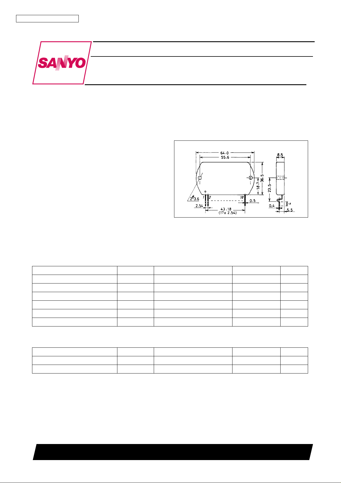
• Small-sized package whose pin assignment is the same
Package Dimensions
unit: mm
4040
[STK4172 II ]
as that of the STK4101II series
• Built-in muting circuit to cut off various kinds of pop
noise
• Greatly reduced heat sink due to substrate temperature
125 ° C guaranteed
• Excellent cost performance
Specifications
Maximum Ratings
Parameter Symbol Conditions Ratings Unit
Maximum supply voltage V
Thermal resistance
Junction Temperature Tj 150
Operating substrate temperature Tc 125
Storage temperature Tstg
Available time for load short-circuit ts V
at Ta = 25 ° C
max
CC
j-c 1.8
30 to +125
= ± 32V, R
CC
= 8 Ω , f = 50Hz, Po = 40W 2 s
L
48 V
C/W
C
C
C
Recommended Operating Conditions
Parameter Symbol Conditions Ratings Unit
Recommended supply voltage V
Load resistance R
CC
L
SANYO Electric Co., Ltd. Semiconductor Business Headquarters
TOKYO OFFICE Tokyo Bldg., 1-10, 1 Chome, Ueno, Taito-ku, TOKYO, 110 JAPAN
at Ta = 25 ° C
32 V
Ω
70997HA (ID) / O138YT / 9068MO, TS No. 2323—1/8
STK4172 II
Operating Characteristics
at Ta = 25 ° C, V
R
: non-inductive load
L
= ± 32V, R
CC
Parameter Symbol Conditions min typ max Unit
Quiescent current I
P
CCO
(1)
O
Output power
(2)
P
O
Total harmonic distortion THD P
Frequency response f
Input impedance r
Output noise voltage V
Neutral voltage V
Muting voltage V
, f
L
H
i
NO
N
M
V
= ± 38.5V 20 40 100 mA
CC
THD = 0.4%,
f = 20Hz to 20kHz
V
= ± 29V, THD = 1.0%,
CC
R
= 4 Ω , f = 1kHz
L
= 1.0W, f = 1kHz 0.3 %
O
P
O
P
O
V
CC
V
CC
+0
= 1.0W, dB 20 to 50k Hz
–3
= 1.0W, f = 1kHz 55 k Ω
= ± 38.5V, Rg = 10k Ω
= ± 38.5V –70 0 +70 mV
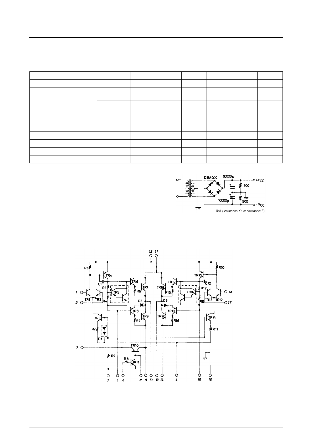
Notes. For power supply at the time of test, use a constant-voltage po w er supply
unless otherwise specified.
For measurement of the available time for load short-circuit and output
noise voltage, use the specified transformer power supply shown right.
The output noise voltage is represented by the peak value on rms scale
(VTVM) of average value indicating type. For AC power supply, use an
AC stabilized power supply (50Hz) to eliminate the effect of flicker noise
in AC primary line.
= 8 Ω , Rg = 600 Ω , VG = 40dB,
L
40 W
45 W
–2 –5 –10 V
Specified Transformer Power Supply
(Equivalent to MG-200)
1.2 mVrms
Equivalent Circuit
No. 2323—2/8
STK4172 II
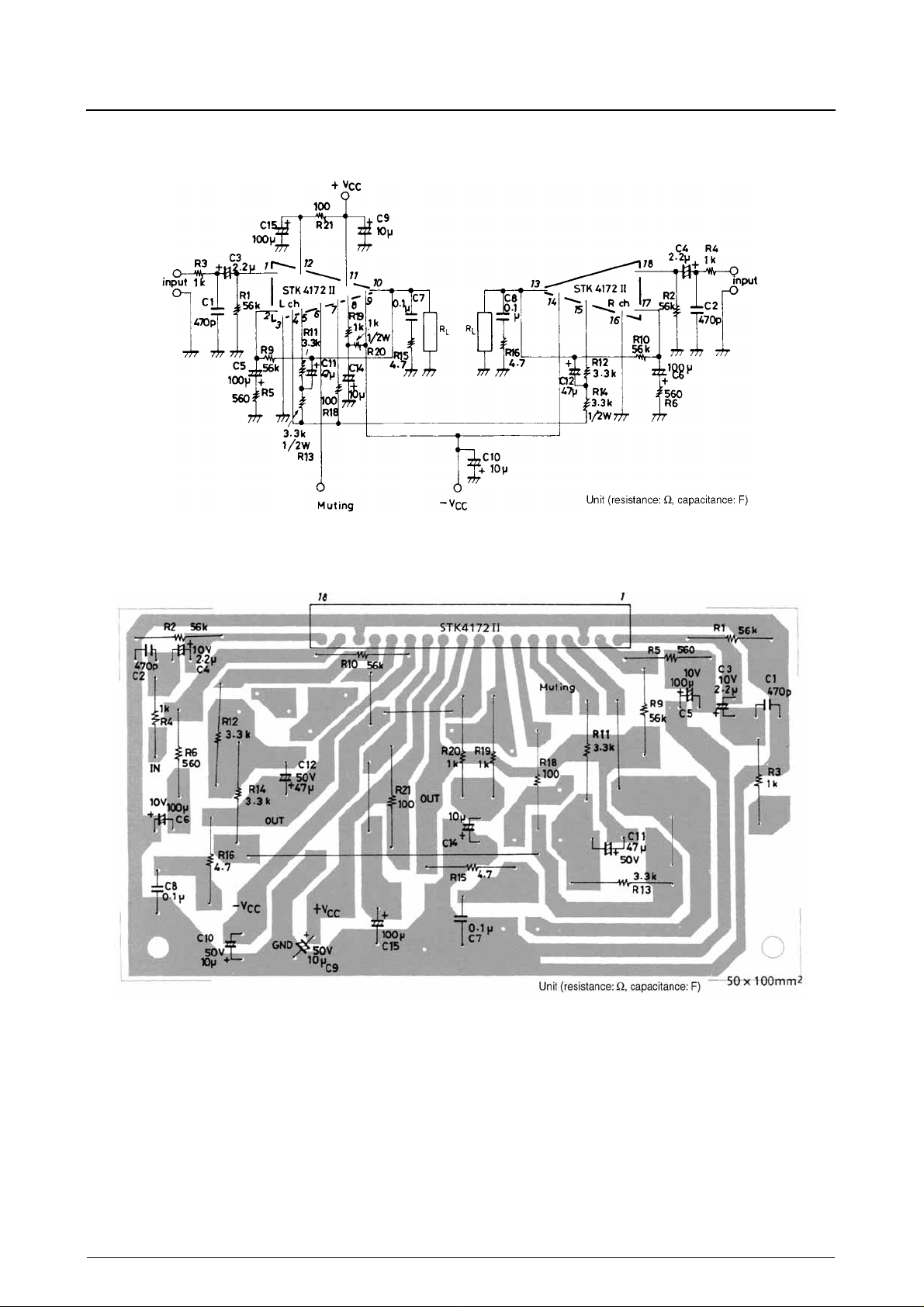
Sample Application Circuit (I)
40W min 2-channel AF power amplifier
Sample Printed Circuit Pattern for Application Circuit
(Cu-foiled side)
No. 2323—3/8
 Loading...