

Page 1

Speaker System
3-864-740-03(1)
Operating Instructions Page 2
Mode d’emploi Page 16
Bedienungsanleitung Seite 30
お買い上げいただきありがとうございます。
警告
この取扱説明書には、事故を防ぐための重要な注意事項と製品の取り扱いかたを示
してあります。この取扱説明書をよくお読みのうえ、製品を安全にお使いください。
お読みになったあとは、いつでも見られるところに必ず保管してください。
電気製品は、安全のための注意事項を守らないと、
火災や人身事故になることがあります。
Manual de instrucciones Página 46
Istruzioni per l’uso Pagina 60
取扱説明書
74
ペ−ジ
SS-X500A
1998 by Sony Corporation
Page 2

English
WARNING
To prevent fire or shock hazard, do not
expose the unit to rain or moisture.
Page 3

English
Table of Contents
Features
Features .....................................................................3
Precautions................................................................4
Parts List.................................................................... 5
Parts Identification.................................................... 6
Installing the Speakers ............................................. 7
Installing the Speakers on a Wall......................9
Changing the Speaker Angles .........................10
Attaching the Ferrite Filters ...................................11
Connecting to the Monitor ..................................... 12
Connecting to the Amplifier ................................... 14
Specifications.......................................................... 15
The SS-X500A is a two-way bass reflex speaker system
which adopts a cone-type woofer and tweeter. This speaker
system is designed for use with the PFM-500A1WU/A1WE
flat panel monitor. The metal mesh grill has been designed
to improve the quality of the sound. You can enjoy the high
quality stereo sound.
EN
English
3
Page 4

Precautions
Operating and storage locations
Avoid operating or storing the product in the following
locations.
• Extremely hot or cold places
• In direct sunlight for long periods, or close to heating
equipment
• Damp or dusty places
• Where it is exposed to rain
• Locations subject to strong vibration
Care
• Clean the cabinet with a soft, dry cloth. If it is very dirty,
use a cloth dampened with a small quantity of neutral
detergent, then wipe dry.
• Avoid the use of volatile solvents such as alcohol, benzene,
and thinners. They may damage the surface finish, or
impair the operation of the shutter adaptor.
Ventilation
Do not wrap the unit in a cloth, etc., during operation. This
may cause the internal temperature to rise excessively and
the unit to malfunction.
Miscellaneous
• Be careful not to spill water or other liquids on the unit or
allow combustible or metallic objects inside the body. If
used with foreign objects inside, the unit is liable to fail or
cause a fire or an electric shock.
• If the product is transported or shipped, repack it as
originally packed at the factory, or in materials equal in
quality.
• Avoid driving the speaker system continuously with an
input exceeding the maximum input power of this speaker
system.
• Before connecting, turn off the amplifier to avoid
damaging the speaker system.
• If the +/– connection is incorrect, the bass tones seem to be
missing and the position of the instruments becomes
obscure.
In the event of any problems with the operation of the unit,
contact your Sony service representative.
4
Page 5

Parts List
Speaker (2)
Bracket (2)
L
R
Speaker attachment screw
(black, M5×9) (6)
Bracket attachment screw
(gray, M4×14) (8)
Speaker cord 2.5 m (2)
Speaker cord holder (4)
Ferrite filter (4)
5
Page 6
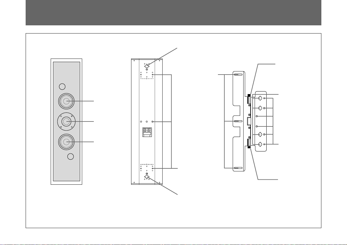
Parts Identification
R
L
Woofer
Tweeter
Wall
attachment
hole
attachment
Speaker
holes
Angle lock
screw
Bracket
attachment
holes
Speaker Front
Woofer
RL
Speaker Rear
Speaker
attachment
holes
Wall
attachment
hole
Wall
attachment
holes
Angle lock
screw
Bracket
6
Page 7
Installing the Speakers
Right Speaker
RL R
Speaker
attachment
holes
L
Brackets
Install the right/left speakers using the brackets as follows:
Left Speaker
1 Match the speaker attachment holes on the speaker to
R
RL
L
The L-marks must be
aligned side by side.
R
RL
L
the speaker attachment holes on the bracket. Attach the
brackets to the speakers with the supplied M5 screws
(black, 3 screws each for left and right holes).
Assemble the left speaker by matching the L-mark of
the speaker to the L-mark of the bracket. (The L-marks
must be aligned side by side.)
Similarly, you can install the right speaker by matching
the R-mark of the speaker to the R-mark of the bracket.
(The R-marks must be aligned side by side.)
2 Loosen the panel cover screws (2 each for right and
left). Open the panel cover.
There are 4 bracket attachment holes to install the
speakers.
3 Insert the supplied M4 screws (gray, 4 screws each for
right and left) into the bracket attachment holes and
temporarily tighten them.
Panel cover
screws
Bracket
attachment
holes
Bracket
attachment
screws
7
Page 8
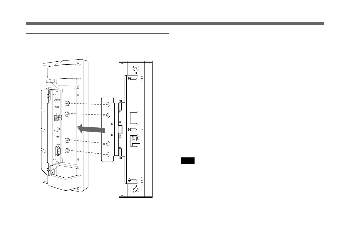
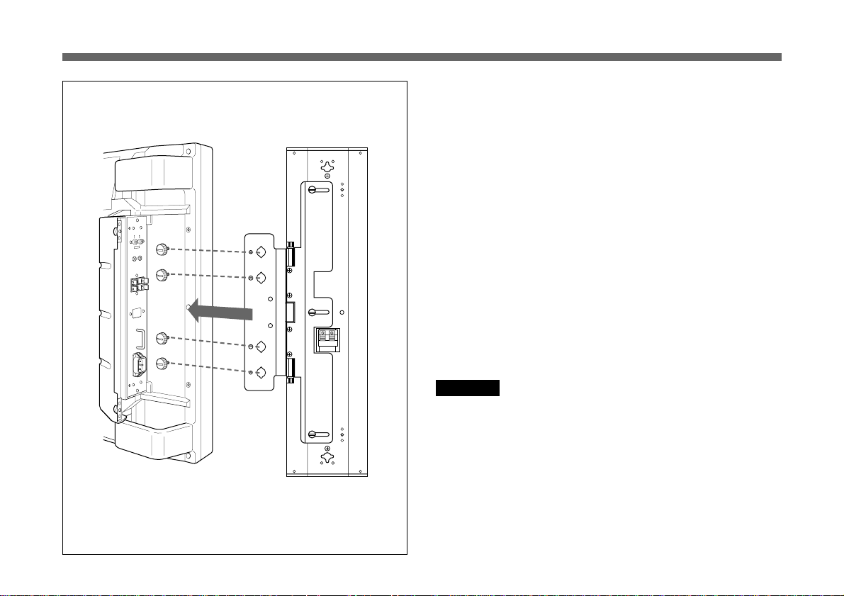
Installing the Speakers
4 Hook the bracket attachment holes on the bracket onto
the screws temporarily tightened in Step 3. Install the
speakers.
5 Tighten the screws completely with a coin and lock the
speakers.
6 Connect the speaker to the monitor with the supplied
cord.
For more details, see “Connecting to the Monitor” on
page 12.
7 Close the panel cover and tighten the panel cover
screws (2 screws each for right and left.)
To remove the speakers
Reverse the installation process.
Note
R
Only use the supplied screws when installing the speakers.
Monitor
Speaker
8
Page 9

Installing the Speakers on a Wall
When you use a bracket
L
Wall attachment holes (φ 6 mm)
R
When you do not use a bracket
)
inches
4
/
3
21
(
552 mm
Wall attachment holes
You can install the speakers on a wall using the wall
attachment screw holes of the brackets and speakers.
You can change the speaker angles if you have installed the
speakers with the brackets.
9
Page 10
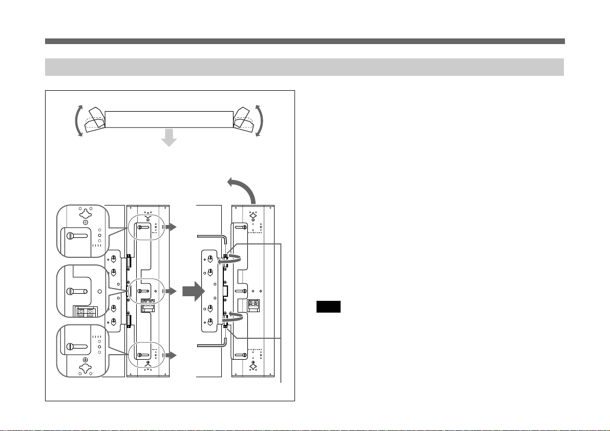
Installing the Speakers
R
RL
L
Changing the Speaker Angles
PFM-500A1WU/A1WE Front
When turning for forward
After installing the speakers on the monitor, you can change
the speaker angle.
To move the speakers far forward, follow the steps below:
1 Loosen the M5 screws (black, 3 screws each for right
and left that fix the speakers and the brackets). Slide out
the speaker.
When fixing the speaker angle, check the scale on the
speaker to fix it evenly.
As the speakers slide out, the speakers move more
toward the front.
10
R
RL
L
R
RL
L
Angle lock screw
2 Move the speakers to change the speaker angle.
3 To lock the speaker angle, tighten the angle lock screw
by hand or with a hexagon wrench.
Note
Do not turn the speaker with excessive force after tightening
the angle lock screw.
Page 11

Attaching the Ferrite Filters
Wrap the speaker cable around the supplied filters four
times to hold them in place.
Speaker cord
to speaker terminal on the
SS-X500A speaker system
Approx. 5 cm
(2 inches)
Tip of the speaker cord
Approx. 5 cm
(2 inches)Ferrite filters
to speaker terminal on the
PFM-500A1WU/A1WE
flat panel monitor
11
Page 12

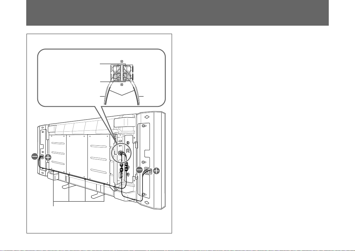
Connecting to the Monitor
Press the button
and insert the
cord into the
proper terminal.
Pull the cord
slightly to make
sure it is
connected firmly.
Right
speaker
Speaker cord holders
Red
buttons
Black
buttons
Red
cord
SPEAKERS
(6-16 Ω)
+
L
–
–
Black cords
+
R
–
Red
cord
Left
speaker
Before connecting the speakers to the monitor, be
sure to turn off the monitor’s power.
Connect the speakers to the monitor while the panel cover
on the monitor is open.
For details on how to install the speakers to the monitor, see
“Installing the Speakers” on page 7.
1 Connect the speaker cords to the monitor speaker
terminals.
Make sure the R (Right) speaker and L (Left) speaker
are connected to the R (Right) terminals and L (Left)
terminals on the monitor respectively.
Match the polarity of the speaker terminals with the
polarity of the speaker terminals on the monitor, ‘ to
‘ with the red cord and ’ to ’ with black cord.
2 Connect the speaker cords to the speakers.
Make sure to connect the R (Right) cord to the right
speaker and the L (Left) cord to the left speaker.
When you connect the cord to the right speaker, pull out
the cord from under the monitor panel cover and lay it
under the monitor to the right speaker.
Use the supplied speaker cord holders to tuck the cord.
For details on how to attach the speaker cord holder,
see “To install the speaker cord holders” on next page.
Similarly, when you connect the cord to the left speaker,
pull out the cord from under the monitor panel cover
and lay it under the monitor to the left speaker.
Tuck any excess cord inside the panel cover.
12
3 Close the right and left panel covers.
Page 13

Securely insert the
holders into the holes
on the ventilation
openings.
To install the speaker cord holders
As shown in the figure, insert the holders into the holes on
the ventilation openings.
Evenly space the holders and insert them under the monitor
cover.
2 cm
(13/16 inches)
Monitor cover
To use an optional
mounting bracket,
insert the holders
where the brackets are
not installed. See the
figure.
If you use an optional mounting bracket, the bracket
position and the holder positions should not overlap.
Notes
• Be careful not to short-circuit the speaker terminals
according to the wire sticking out of the insulation.
• Connect the speaker cords with correct polarity. Correct
‘’ connections of both speaker systems insures proper
inphase operation. If the speaker system is out-of-phase,
the bass tones seem to be missing and the position of the
sound sources become obscure.
• Do not connect the speakers to both an amplifier and a
monitor at the same time. Otherwise, the excessive electric
current may flow from the amplifier to the monitor via the
speaker cord, which may damage the monitor.
13
Page 14
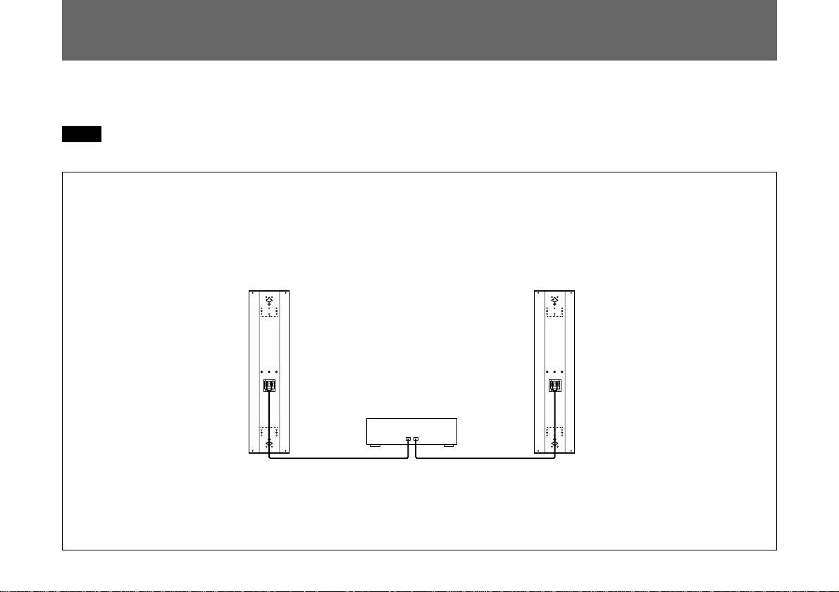
Connecting to the Amplifier
Connect the cord to the speaker terminals of the AV
amplifier.
Notes
• The amplifier output must be 120W or less.
Right speaker
RL RL
• Do not connect the speaker system to the monitor and an
amplifier. Doing so may cause a large amount of current
to flow into the monitor from the amplifier via the speaker
cord, resulting in damage to the monitor.
Left speaker
AV amplifier
14
Page 15
Specifications
Speaker system
Woofer × 2, magnetically shielded
Tweeter × 1, magnetically shielded
Speaker unit 8 cm (3 1/4 inches), cone type
2.5 cm (1 inch), dome type
Enclosure type
Bass reflex
Rated impedance
8 ohms
Power handling capacity
Maximum input power: 120 W
Characteristic sensitivity level
88 dB (1 W, 1 m)
Effective frequency range
70 Hz to 20,000 Hz
Operating conditions
Temperature 0°C to +35°C (32°F to 95°F)
Humidity 0% to +90% (no condensation)
Pressure 700 hPa to 1,060 hPa
Transport and storage conditions
Temperature –10°C to +40°C (14°F to
104°F)
Humidity 0% to +90% (no condensation)
Pressure 700 hPa to 1,060 hPa
Dimensions Approx. 159 × 634 × 90 mm (6 3/8 × 25 ×
3 5/8 inches) (w/h/d), including front grille
(net per speaker)
Mass Approx. 3.5 kg (7 lb 11 oz) (net per speaker)
Approx. 1.1 kg (2 lb 7 oz) (net per bracket)
Supplied accessories
Speaker cord (2, 2.5 m)
Speaker attachment screw (6)
Bracket attachment screw (8)
Speaker cord holder (4)
Ferrite filter (4)
Operating instructions (1)
Design and specifications are subject to change without
notice.
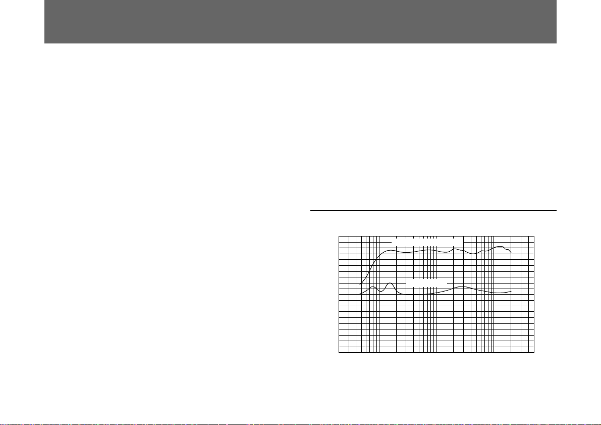
Characteristic curves
100
90
80
70
60
50
40
30
20
Sound Pressure Level in dB
10
0
20 50
Frequency response
Impedance
8
100 200 500 1K 2K 5K 10K 20K 50K
Frequency in Hz
Impedance in ohms
15
Page 16

Français
AVERTISSEMENT
Afin d’eviter tout risque d’incendie ou
d’électrocution, ne pas exposer cet
appareil à la pluie ou à l’humidité.
Page 17

Français
Table des matières
Caractéristiques
Caractéristiques ...................................................... 17
Précautions..............................................................18
Liste des composants ............................................ 19
Identification des composants .............................. 20
Installation des haut-parleurs ................................ 21
Installation des haut-parleurs au mur ..............23
Changement de l’angle des haut-parleurs .......24
Installation des filtres en ferrite............................. 25
Raccordement au moniteur....................................26
Raccordement à l’amplificateur............................. 28
Spécifications.......................................................... 29
Le SS-X500A est un système de haut-parleurs bass reflex à
deux voies intégrant un woofer et un tweeter en cône. Ce
système de haut-parleurs est conçu en vue d’une utilisation
avec un moniteur à écran plat PFM-500A1WU/A1WE. La
grille métallique a été étudiée pour permettre une
optimisation de la qualité sonore. Vous pouvez de ce fait
pleinement exploiter une haute qualité sonore stéréo.
F
Français
17
Page 18

Précautions
Lieu d’utilisation et de stockage
Evitez d’utiliser ou de stocker l’unité dans des endroits :
• extrêmement chauds ou froids;
• soumis au rayonnement direct du soleil durant de longues
périodes ou à proximité d’un système de chauffage;
• humides ou poussiéreux;
• exposés à la pluie;
• soumis à de fortes vibrations;
Entretien
• Nettoyez le châssis avec un chiffon doux et sec. S’il est
fortement souillé, utilisez un chiffon légèrement imprégné
d’une solution détergente neutre et essuyez-le ensuite.
• N’utilisez pas de solvants volatiles comme de l’alcool, du
benzène ou des diluants. Ils risquent de ternir le fini du
châssis ou de perturber le bon fonctionnement de
l’adaptateur d’obturation.
Ventilation
N’enveloppez pas l’unité dans du tissu, etc., en cours de
fonctionnement. Cela risque d’entraîner une augmentation
excessive de la température intérieure et un
dysfonctionnement de l’unité.
Divers
• Veillez à ne pas répandre d’eau ou un autre liquide sur
l’unité; prévenez toute pénétration éventuelle de matériaux
combustibles ou métalliques dans le châssis. En cas de
pénétration d’un corps étranger à l’intérieur du châssis,
l’unité est susceptible de tomber en panne, de prendre feu
ou de provoquer une électrocution.
• Si l’unité doit être transportée ou expédiée, remballez-la
dans son conditionnement d’origine ou dans des matériaux
de qualité équivalente.
• Evitez de faire fonctionner les enceintes de manière
continue avec une entrée qui excède la puissance d’entrée
maximum de ce système.
• Avant d’effectuer les connexions, mettez l’amplificateur
hors tension pour éviter d’endommager les enceintes.
• Si les bornes +/– ne sont pas raccordées correctement, les
tonalités basses sembleront absentes et la position des
instruments sera confuse.
Si vous rencontrez des problèmes d’utilisation avec cet
appareil, consultez un représentant du service après-vente
Sony.
18
Page 19

Liste des composants
Haut-parleur (2)
Support (2) Vis de fixation de haut-parleur
(noir, M5×9) (6)
L
Vis de fixation de support
(gris, M4×14) (8)
R
Cordon de haut-parleur
(2,5 m) (2)
Crochet à cordon de
haut-parleur (4)
Filtre en ferrite (4)
19
Page 20

Identification des composants
R
L
Orifice de
fixation
murale
Woofer
Tweeter
Orifices de
fixation de
haut-parleur
Vis de réglage
d’angle
Orifices de
fixation de
support
Haut-parleur
avant
Woofer
RL
Haut-parleur
arrièr
Orifices de
fixation de
haut-parleur
Orifice de
fixation
murale
Orifice de
fixation
murale
Vis de réglage
d’angle
Support
20
Page 21

Installation des haut-parleurs
Haut-parleur
droit
RL R
Orifices de
fixation de
haut-parleur
L
Supports
Haut-parleur
gauche
R
R
Installez les haut-parleurs gauche et droit à l’aide des
supports de montage en procédant comme suit :
1 Alignez les orifices de fixation de haut-parleur du haut-
parleur sur les orifices correspondants du support. Fixez
les supports aux haut-parleurs à l’aide des vis M5
fournies (noires, 3 à gauche et à droite).
Montez le haut-parleur gauche en alignant le repère “L”
du haut-parleur sur le repère “L” du support. (Les
repères “L” doivent être alignés côte à côte.)
RL
L
RL
L
De même, vous pouvez installer le haut-parleur droit en
alignant le repère “R” du haut-parleur sur le repère “R”
du support. (Les repères “R” doivent être alignés côte à
Les repères L doivent
être alignés côte à côte.
côte.)
2 Desserrez les vis du couvercle de panneau (2 à gauche
et à droite). Ouvrez le couvercle de panneau.
Quatre orifices de fixation de support sont prévus pour
l’installation des haut-parleurs.
3 Introduisez les vis M4 fournies (grises, 4 à gauche et à
droite) dans les orifices de fixation de support et serrezles provisoirement.
Vis du couvercle
de panneau
Orifices de
fixation de
support
Vis de
fixation de
support
21
Page 22
Installation des haut-parleurs
4 Accrochez provisoirement les orifices de fixation de
support aux vis que vous avez serrées à l’étape 3.
Installez les haut-parleurs.
5 Serrez les vis à fond à l’aide d’une pièce de monnaie ou
d’un tournevis et bloquez les haut-parleurs.
6 Raccordez le haut-parleur au moniteur au moyen du
cordon fourni.
Pour plus de détails, voir “Raccordement au moniteur”
à la page 26.
7 Refermez le couvercle de panneau et serrez les vis du
couvercle de panneau (2 à gauche et à droite).
Pour déposer les haut-parleurs
Inversez la procédure d’installation.
Remarque
R
Pour l’installation des haut-parleurs, utilisez uniquement les
vis fournies.
22
Moniteur
Haut-parleur
Page 23

Installation des haut-parleurs au mur
Si vous utilisez un support
L
Orifices de fixation murale
(φ 6 mm)
R
Si vous n’utilisez pas de support
)
pouces
4
/
3
21
(
552 mm
Orifices de fixation murale
Vous pouvez installer les haut-parleurs au mur à l’aide des
trous de vissage pour fixation murale des supports et des
haut-parleurs.
Si vous avez installé les haut-parleurs sur les supports, vous
pouvez en changer l’angle d’orientation.
23
Page 24

Installation des haut-parleurs
R
RL
L
Changement de l’angle des haut-parleurs
Après avoir installé les haut-parleurs sur le moniteur, vous
pouvez changer l’angle des haut-parleurs.
Pour faire pivoter les haut-parleurs tout à fait vers l’avant,
procédez comme suit :
24
PFM-500A1WU/A1WE Avant
Pour tourner vers l’avant
R
RL
L
Vis de réglage d’angle
R
RL
L
1 Desserrez les vis M5 (noires, 3 à gauche et à droite, qui
fixent les haut-parleurs et les supports). Faites pivoter
les haut-parleurs vers l’extérieur.
Lors de l’ajustage de l’angle des haut-parleurs,
contrôlez l’échelle graduée des haut-parleurs de façon à
les ajuster de manière uniforme.
En pivotant vers l’extérieur, les haut-parleurs s’orientent
davantage vers l’avant.
2 Faites pivoter les haut-parleurs pour en modifier l’angle.
3 Pour bloquer les haut-parleurs suivant l’angle voulu,
serrez les vis de réglage d’angle à la main ou à l’aide
d’une clé à tête hexagonale.
Remarque
N’exercez pas une force excessive pour faire pivoter les
haut-parleurs après avoir serré la vis de réglage d’angle.
Page 25

Installation des filtres en ferrite
Enroulez quatre fois le cordon de haut-parleur autour des
filtres fournis de façon à les maintenir en place.
Cordon de haut-parleur
Approx. 5 cm
(2 pouces)
vers la borne de haut-parleur
de l’enceinte SS-X500A
Extrémité du cordon de
haut-parleur
Approx. 5 cm
(2 pouces)Filtres en ferrite
vers la borne de haut-parleur du
moniteur à écran plat
PFM-500A1WU/A1WE
25
Page 26
Raccordement au moniteur
Appuyez sur le
bouton et
introduisez le fil
dans la borne
appropriée.
Tirez légèrement
sur le fil pour vous
assurer qu’il est
correctement
raccordé.
Hautparleur
droit
Crochets à cordon de
haut-parleur
Boutons
rouges
Boutons
noirs
Fil
rouge
SPEAKERS
(6-16 Ω)
+
L
–
–
Fils noirs
+
R
–
Fil
rouge
Haut-parleur
gauche
Avant de raccorder les haut-parleurs au moniteur,
veillez à mettre le moniteur hors tension.
Raccordez les haut-parleurs au moniteur pendant que le
couvercle de panneau du moniteur est ouvert.
Pour plus de détails sur l’installation des haut-parleurs sur
le moniteur, voir “Installation des haut-parleurs” à la page
21.
1 Branchez les cordons de haut-parleur sur les bornes de
haut-parleur du moniteur.
Assurez-vous que le haut-parleur droit (R) et le hautparleur gauche (L) sont respectivement raccordés aux
bornes droites (R) et gauches (L) du moniteur.
Faites correspondre la polarité des bornes des hautparleurs à la polarité des bornes de haut-parleur du
moniteur : ‘ avec ‘ à l’aide du cordon rouge et ’
avec ’ à l’aide du cordon noir.
2
Raccordez les cordons de haut-parleur aux haut-parleurs.
Raccordez le cordon droit (R) au haut-parleur droit et le
cordon gauche (L) au haut-parleur gauche.
Pour raccorder le cordon au haut-parleur droit, tirez le
cordon sous le couvercle de panneau du moniteur et faitesle passer sous le moniteur jusqu’au haut-parleur droit.
Utilisez les crochets à cordon de haut-parleur fournis
pour maintenir le cordon.
Pour plus de détails sur la fixation des crochets à
cordon de haut-parleur, voir “Installation des crochets
à cordon de haut-parleur” à la page suivante.
26
Page 27

Introduisez
correctement les
crochets dans les
ouïes de
ventilation.
2 cm
(13/16 pouces)
Couvercle du moniteur
Si vous utilisez un
support de montage
en option, introduisez
les crochets à d’autres
endroits que là où les
supports sont installés.
Voir Figure.
De même, pour le cordon au haut-parleur gauche, tirez
le cordon sous le couvercle de panneau du moniteur et
faites-le passer sous le moniteur jusqu’au haut-parleur
gauche.
Dissimulez la longueur de cordon excessive derrière le
couvercle de panneau.
3 Refermez les couvercles de panneau gauche et droit.
Installation des crochets à cordon de haut-parleur
Comme illustré dans la Figure, introduisez les crochets dans
les orifices des ouïes de ventilation.
Installez les crochets à intervalles réguliers et insérez-les
sous le couvercle du moniteur.
Si vous utilisez un support de montage en option, la position
du support ne peut interférer avec la position des crochets.
Remarques
• Veillez à ne pas court-circuiter les bornes de hautparleur avec une partie de fil dénudée qui dépasse.
• Raccordez les câbles de haut-parleur en en respectant la
polarité. Un raccordement ‘’ correct des deux enceintes
vous assure un fonctionnement en phase correct. Si
l’enceinte est hors phase, les graves sembleront absentes et
la position de la source sonore imprécise.
• Ne branchez pas simultanément les haut-parleurs à un
amplificateur et à un moniteur. Sinon, le flux de courant
excessif transmis de l’amplificateur au moniteur via le
cordon de haut-parleur risque d’endommager le moniteur.
27
Page 28

Raccordement à l’amplificateur
Branchez les cordons de haut-parleur sur les bornes de hautparleur de l’amplificateur AV.
Remarques
• La puissance de sortie de l’amplificateur doit être de
120 W ou moins.
Haut-parleur
droit
Amplificateur AV
RL RL
• Ne raccordez pas le système de haut-parleurs au moniteur
et à un amplificateur. Vous risquez sinon de provoquer un
passage de courant important de l’amplificateur dans le
moniteur via le cordon de haut-parleur, ce qui causerait des
dommages au moniteur.
Haut-parleur
gauche
28
Page 29

Spécifications
Système de haut-parleur
Woofer × 2, blindage magnétique
Tweeter × 1, blindage magnétique
Haut-parleur 8 cm (3 1/4 pouces), en cône
2,5 cm (1 pouce), en dôme
Type d’enceinte
Bass reflex
Impédance nominale
8 ohms
Charge nominale efficace
Puissance d’entrée maximum: 120 W
Niveau de sensibilité caractéristique
88 dB (1 W, 1 m)
Plage de fréquence effective
70 Hz à 20.000 Hz
Conditions d’utilisation
Température
0°C à +35°C (32°F à 95°F)
Humidité 0 % à +90 % (sans condensation)
Pression atmosphérique
700 hPa à 1.060 hPa
Conditions de transport et de stockage
Température
–10°C à +40°C (14°F à 104°F)
Humidité 0 % à +90 % (sans condensation)
Pression atmosphérique
700 hPa à 1.060 hPa
Dimensions Approx. 159 × 634 × 90 mm (6 3/8 × 25 × 3 5/8
pouces) (l/h/p), grille frontale comprise
(nettes par haut-parleur)
Masse Approx. 3,5 kg (7 lb 11 oz)
(nette par haut-parleur)
Approx. 1,1 kg (2 lb 7 oz)
(nette par haut-parleur)
Accessoires fournis
Cordon de haut-parleur (2, 2,5 m)
Vis de fixation de haut-parleur (6)
Vis de fixation de support (8)
Crochet à cordon de haut-parleur (4)
Filtre en ferrite (4)
Mode d’emploi (1)
La conception et les spécifications sont sujettes à
modifications sans préavis.
Courbes caractéristiques
100
90
80
70
60
50
40
Réponse en dB
30
20
10
0
20 50
Réponse en fréquence
Impédance
100 200 500 1K 2K 5K 10K 20K 50K
Fréquence in Hz
8
Impédance en ohms
29
Page 30

Deutsch
VORSICHT
Um Feuergefahr und die Gefahr eines
elektrischen Schlages zu vermeiden, darf
das Gerät weder Regen noch Feuchtigkeit
ausgesetzt werden.
Page 31

Deutsch
Inhalt
Merkmale und Funktionen
Merkmale und Funktionen......................................31
Sicherheitsmaßnahmen..........................................32
Teileliste................................................................... 33
Lage und Funktion der Teile und
Bedienelemente .................................................34
Installieren der Lautsprecher................................. 35
Montieren der Lautsprecher an der Wand.......37
Ändern der Winkel der Lautsprecher ..............38
Anbringen der Ferritfilter........................................39
Anschließen an den Monitor .................................. 40
Anschließen an den Verstärker ............................. 43
Technische Daten ................................................... 44
Das SS-X500A ist ein 2-Wege-BaßreflexLautprechersystem mit Konustief- und -hochtöner. Dieses
Lautsprechersystem kann an den Flachmonitor PFM500A1WE angeschlossen werden. Das Frontgitter aus
Metall wurde zur Erhöhung der Klangqualität entwickelt. So
wird Stereoton in optimaler Qualität wiedergegeben.
D
Deutsch
31
Page 32

Sicherheitsmaßnahmen
Geeignete Umgebungen für Betrieb und
Lagerung
Benutzen und lagern Sie das System nicht an Orten, an
denen es folgenden Bedingungen ausgesetzt ist:
• Extremer Hitze oder Kälte
• Direktem Sonnenlicht über einen längeren Zeitraum
hinweg oder dem Einfluß von Wärmequellen wie z. B.
Heizungen
• Feuchtigkeit oder Staub
• Regen
• Starken Vibrationen
Pflege des Systems
• Reinigen Sie das System mit einem weichen, trockenen
Tuch. Hartnäckige Verschmutzungen entfernen Sie mit
einem Tuch, das Sie leicht mit etwas neutralem
Reinigungsmittel angefeuchtet haben. Wischen Sie das
Gehäuse anschließend trocken.
• Verwenden Sie keine flüchtigen Lösungsmittel wie
Alkohol, Benzin oder Verdünner. Diese könnten die
Gehäuseoberfläche angreifen.
Luftzufuhr
Wickeln Sie das System während des Betriebs nicht in
Tücher o. ä. ein. Dies könnte zu einer Überhitzung und
damit zu Fehlfunktionen führen.
Sonstiges
• Verschütten Sie kein Wasser oder sonstige Flüssigkeiten
auf dem System. Achten Sie darauf, daß keine brennbaren
oder metallenen Objekte in das System hineingelangen.
Wenn Sie das System benutzen, nachdem Fremdkörper
hineingelangt sind, besteht die Gefahr einer Fehlfunktion,
eines elektrischen Schlags oder eines Brands.
• Verpacken Sie das System für einen Transport wieder in
der Original- oder in einer gleichwertigen Verpackung.
• Steuern Sie das Lautsprechersystem nicht über längere Zeit
mit einer über der Belastbarkeit liegenden Leistung an.
• Schalten Sie vor dem Anschließen den Verstärker aus, um
eine Beschädigung des Lautsprechersystems zu vermeiden.
• Wenn + und – nicht korrekt angeschlossen sind, fehlen
scheinbar die Bässe, und die Raumposition der Instrumente
ist nicht mehr auszumachen.
Sollten an Ihrem System Probleme auftreten, wenden Sie
sich bitte an Ihren Sony-Kundendienst.
32
Page 33

Teileliste
Lautsprecher (2)
Halterung (2)
L
R
Lautsprechermontageschraube
(schwarz, M5×9) (6)
Halterungsmontageschraube
(grau, M4×14) (8)
Lautsprecherkabel (2,5 m) (2)
Halter für Lautsprecherkabel (4)
Ferritfilter (4)
33
Page 34

Lage und Funktion der Teile und Bedienelemente
R
L
Wandmontagebohrung
Lautsprecher-
montage-
bohrungen
Tieftöner
Hochtöner
Winkelfeststell-
schraube
Halterungsmontagebohrungen
Vorderseite
Tieftöner
RL
Rückseite
Lautsprecher-
montage-
bohrungen
Wandmontagebohrung
Wandmontagebohrungen
Winkelfeststellschraube
Halterung
34
Page 35

Installieren der Lautsprecher
Rechter
Lautsprecher
RL R
Schrauben der
Anschlußfeldabdeckung
Lautsprechermontagebohrungen
L
Halterungen
R
RL
L
Die L-Markierungen müssen
nebeneinanderliegen.
Halterungsmontagebohrungen
Halterungsmontageschrauben
Linker
Lautsprecher
R
RL
L
Installieren Sie den rechten/linken Lautsprecher mit Hilfe
der Halterungen folgendermaßen:
1 Richten Sie die Lautsprechermontagebohrungen der
Halterung an den Lautsprechermontagebohrungen der
Lautsprecher aus. Bringen Sie die Halterungen mit den
mitgelieferten M5-Schrauben an den Lautsprechern an
(schwarz, 3 Schrauben pro Lautsprecher).
Achten Sie beim Anbringen der Halterung auf die LMarkierung am linken Lautsprecher und auf die LMarkierung einer der Halterungen. Diese beiden LMarkierungen müssen nebeneinanderliegen.
Achten Sie beim Anbringen der Halterung am rechten
Lautsprecher auf die R-Markierung am Lautsprecher
und auf die R-Markierung der anderen Halterung.
Diese beiden R-Markierungen müssen
nebeneinanderliegen.
2 Lösen Sie die Schrauben der Anschlußfeldabdeckung
(2 an jeder Seite). Öffnen Sie die
Anschlußfeldabdeckung.
Hinter der Abdeckung befinden sich
4 Halterungsmontagebohrungen zur Befestigung der
Lautsprecher.
3 Setzen Sie die mitgelieferten M4-Schrauben (grau,
4 Schrauben an jeder Seite) in die
Halterungsmontagebohrungen ein, und ziehen Sie sie
teilweise an.
35
Page 36

Installieren der Lautsprecher
4 Montieren Sie die Lautsprecher am Monitor, indem Sie
die Halterungsmontagebohrungen der Halterung in die
Schrauben einhängen, die Sie in Schritt 3 teilweise
angezogen haben.
5 Ziehen Sie die Schrauben mit einer Münze fest an, um
die Lautsprecher sicher zu befestigen.
6 Schließen Sie die Lautsprecher mit den mitgelieferten
Kabeln an den Monitor an.
Näheres hierzu finden Sie unter “Anschließen an den
Monitor” auf Seite 40.
7 Schließen Sie die Anschlußfeldabdeckung, und ziehen
Sie die Schrauben der Anschlußfeldabdeckung (2 an
jeder Seite) an.
So nehmen Sie die Lautsprecher ab
Machen Sie die zur Montage der Lautsprecher ausgeführten
Schritte rückgängig.
R
Hinweis
Verwenden Sie zur Montage der Lautsprecher
ausschließlich die mitgelieferten Schrauben.
36
Monitor
Lautsprecher
Page 37

Montieren der Lautsprecher an der Wand
Wenn Sie eine Halterung verwenden
L
Wandmontagebohrungen
(φ 6 mm)
R
Wenn Sie die keine Halterung verwenden
Wandmontagebohrungen
552 mm
Über die Wandmontagebohrungen der Halterungen und
Lautsprecher können Sie die Lautsprecher auch an der
Wand befestigen.
Wenn Sie die Lautsprecher mit den Halterungen montieren,
läßt sich der Lautsprecherwinkel ändern.
37
Page 38

Installieren der Lautsprecher
R
RL
L
Ändern der Winkel der Lautsprecher
Nachdem Sie die Lautsprecher am Monitor angebracht
haben, können Sie den Lautsprecherwinkel ändern.
Gehen Sie wie im folgenden erläutert vor, wenn Sie die
Lautsprecher weiter nach vorn drehen wollen:
38
PFM-500A1WE Vorderseite
Drehen der Lautsprecher nach vorne
R
RL
L
Winkelfeststellschraube
R
RL
L
1 Lösen Sie die M5-Schrauben (schwarz, 3 Schrauben an
jeder Seite zum Befestigen von Lautsprechern und
Halterungen). Ziehen Sie die Lautsprecher seitlich
heraus.
Achten Sie beim Feststellen des Lautsprecherwinkels
auf die Skala am Lautsprecher, so daß die Lautsprecher
gleichmäßig eingestellt sind.
Wenn Sie die Lautsprecher herausziehen, lassen sie sich
weiter nach vorn drehen.
2 Bewegen Sie die Lautsprecher, um den
Lautsprecherwinkel zu ändern.
3 Zum Feststellen des Lautsprecherwinkels ziehen Sie die
Winkelfeststellschraube von Hand oder mit einem
Sechskantschlüssel fest an.
Hinweis
Drehen Sie den Lautsprecher nicht mit übermäßiger Gewalt,
nachdem Sie die Winkelfeststellschraube angezogen haben.
Page 39

Anbringen der Ferritfilter
Wickeln Sie das Lautsprecherkabel viermal um die
mitgelieferten Filter, damit sie nicht verrutschen.
Ende des
Lautsprecherkabels
an Lautsprecheranschluß
des Lautsprechersystems
SS-X500A
Lautsprecherkabel
Ferritfilter
ca. 5 cm
ca. 5 cm
an Lautsprecheranschluß des
Flachmonitors PFM-500A1WE
39
Page 40

Anschließen an den Monitor
Taste drücken
und Kabel in
entsprechenden
Anschluß
einführen.
Sitz des Kabels
durch leichtes
Ziehen
überprüfen.
Rechter
Lautsprecher
Lautsprecherkabelhalter
Rote
Tasten
Schwarze
Tasten
Rotes
Kabel
SPEAKERS
(6-16 Ω)
+
L
–
–
Schwarze
Kabel
+
R
–
Rotes
Kabel
Linker
Lautsprecher
Schalten Sie unbedingt den Monitor aus, bevor Sie
die Lautsprecher an den Monitor anschließen.
Zum Anschließen der Lautsprecher an den Monitor muß die
Anschlußfeldabdeckung des Monitors geöffnet sein.
Näheres zum Montieren der Lautsprecher am Monitor
finden Sie unter “Installieren der Lautsprecher” auf Seite
35.
1 Schließen Sie die Lautsprecherkabel an die
Lautsprecheranschlüsse des Monitors an.
Achten Sie darauf, den rechten Lautsprecher mit den
rechten Lautsprecheranschlüssen und den linken
Lautsprecher mit den linken Lautsprecheranschlüssen
am Monitor zu verbinden.
Achten Sie auch darauf, die Lautsprecheranschlüsse am
Monitor und an den Lautsprechern polaritätsrichtig
miteinander zu verbinden: ‘ zu ‘ (rotes Kabel) und ’
zu ’ (schwarzes Kabel).
2 Schließen Sie die Lautsprecherkabel an die
Lautsprecher an.
Achten Sie darauf, das rechte Kabel mit dem rechten
Lautsprecher und das linke Kabel mit dem linken
Lautsprecher zu verbinden.
Wenn Sie das Kabel an den rechten Lautsprecher
anschließen, ziehen Sie das Kabel unter der
Anschlußabdeckung des Monitors hervor, und verlegen
Sie es unter dem Monitor entlang zum rechten
Lautsprecher.
40
Page 41

Setzen Sie die
Halter fest in die
Schlitze der
Lüftungsöffnungen ein.
2 cm
Rückwand des
Monitors
Bei Verwendung gesondert
erhältlicher
Montagehalterungen setzen
Sie die Halter an einer
Stelle ein, an der sie die
Installation der Halterungen
nicht behindern (siehe
Abbildung).
Mit den mitgelieferten Lautsprecherkabelhaltern können
Sie das Kabel befestigen.
Näheres zum Anbringen der Lautsprecherkabelhalter
finden Sie unter “So bringen Sie die
Lautsprecherkabelhalter an” auf der diser Seite.
Wenn Sie das Kabel an den linken Lautsprecher
anschließen, ziehen Sie das Kabel ebenfalls unter der
Anschlußabdeckung des Monitors hervor, und verlegen
Sie es unter dem Monitor entlang zum linken
Lautsprecher.
Wenn die Kabel zu lang sind, können Sie den
überschüssigen Teil hinter die Anschlußfeldabdeckung
stecken.
3 Schließen Sie die Anschlußfeldabdeckung links und
rechts am Monitor.
So bringen Sie die Lautsprecherkabelhalter an
Setzen Sie die Halter wie in der Abbildung gezeigt in die
Schlitze der Lüftungsöffnungen ein.
Bringen Sie die Halter in gleichmäßigen Abständen unter
der Rückwand des Monitors an.
Wenn Sie eine gesondert erhältliche Montagehalterung
verwenden, dürfen Halterungen und Kabelhalter nicht an
derselben Position angebracht werden.
41
Page 42

Anschließen an den Monitor
Hinweise
•
Halten Sie die abisolierten Enden der Kabeladern
voneinander fern. Andernfalls kann es zu einem Kurzschluß
zwischen den Lautsprecheranschlüssen kommen.
• Schließen Sie die Lautsprecherkabel polaritätsrichtig an.
Nur wenn die ‘- und ’-Pole beider Systeme richtig
miteinander verbunden sind, ist die Phaseneinstellung der
Lautsprecher korrekt. Wenn die Phaseneinstellung nicht
stimmt, fehlen scheinbar die Bässe, und die Raumposition
der Tonquelle ist nicht mehr auszumachen.
• Schließen Sie die Lautsprecher nicht gleichzeitig an einen
Verstärker und einen Monitor an. Ansonsten kann über das
Lautsprecherkabel ein Überlaststrom vom Verstärker zum
Monitor fließen und den Monitor beschädigen.
42
Page 43

Anschließen an den Verstärker
Schließen Sie das Kabel an die Lautsprecheranschlüsse des
AV-Verstärkers an.
Hinweise
• Die Leistungsabgabe des Verstärkers darf maximal 120 W
betragen.
Rechter
Lautsprecher
AV-Verstärker
RL RL
• Schließen Sie das Lautsprechersystem nicht an den
Monitor und einen Verstärker an. Andernfalls kann starker
Strom vom Verstärker über das Lautsprecherkabel in den
Monitor eingespeist werden und den Monitor beschädigen.
Linker
Lautsprecher
43
Page 44

Technische Daten
Lautsprechersystem
Tieftöner × 2, mit Magnetabschirmung
Hochtöner × 1, mit Magnetabschirmung
Lautsprechereinheit
8 cm, Konus
2,5 cm, Kalotte
Gehäusetyp Baßreflexsystem
Nennimpedanz
8 Ohm
Belastbarkeit Maximale Eingangsleistung: 120 W
Typischer Schalldruckpegel
88 dB (1 W, 1 m)
Frequenzbereich
70 Hz bis 20.000 Hz
Betriebsbedingungen
Temperatur 0 °C bis +35 °C
Luftfeuchtigkeit
0 % bis +90 % (nicht
kondensierend)
Druck 700 hPa bis 1.060 hPa
Bedingungen bei Lagerung und Transport
Temperatur –10 °C bis +40 °C
Luftfeuchtigkeit
0 % bis +90 % (nicht
kondensierend)
Druck 700 hPa bis 1.060 hPa
Abmessungen
ca. 159 × 634 × 90 mm (B/H/T), einschließlich
Frontgitter (netto pro Lautsprecher)
44
Gewicht ca. 3,5 kg (netto pro Lautsprecher)
ca. 1,1 kg (netto pro Halterung)
Mitgeliefertes Zubehör
Lautsprecherkabel (2, 2,5 m)
Lautsprechermontageschraube (6)
Halterungsmontageschraube (8)
Halter für Lautsprecherkabel (4)
Ferritfilter (4)
Bedienungsanleitung (1)
Änderungen, die dem technischen Fortschritt dienen,
bleiben vorbehalten.
Frequenzgang/Impedanz-Diagramm
100
90
80
70
60
50
Pegel in dB
40
30
20
10
0
20 50
100 200 500 1K 2K 5K 10K 20K 50K
Frequenzgang
Impedanzkurve
Frequenz in Hz
8
Impedanz in Ohm
Page 45

45
Page 46

Español
ADVERTENCIA
Para evitar incendios o el riesgo de
electrocución, no exponga la unidad a la
lluvia ni a la humedad.
Page 47

Español
Indice
Características
Características ........................................................ 47
Precauciones........................................................... 48
Lista de piezas.........................................................49
Identificación de los componentes .......................50
Instalación de los altavoces...................................51
Instalación de los altavoces en la pared ..........53
Cambio de los ángulos de los altavoces ..........54
Fijación de los filtros de ferrita.............................. 55
Conexión al monitor ............................................... 56
Conexión al amplificador ....................................... 58
Especificaciones ..................................................... 59
El SS-X500A es un sistema de altavoces de dos vías de
reflejo de graves que incorpora un altavoz de graves y
agudos de tipo cónico. Este sistema de altavoces está
diseñado para utilizarse con el monitor de panel plano PFM500A1WU/A1WE. La rejilla de malla metálica se ha
diseñado para mejorar la calidad de sonido. Es posible
disfrutar de sonido estéreo de alta calidad.
ES
Español
47
Page 48

Precauciones
Lugares de almacenamiento y funcionamiento
Evite utilizar o almacenar la unidad en los siguientes
lugares:
• Extremadamente calurosos o fríos
• Expuestos a la luz solar directa durante largos períodos de
tiempo, o cercanos a equipos térmicos
• Húmedos o polvorientos
• Expuestos a la lluvia
• Sujetos a vibraciones intensas
Cuidados
• Limpie el exterior con un paño seco y suave. Si está muy
sucio, utilice un paño humedecido con una pequeña
cantidad de detergente neutro y, a continuación, séquelo.
• Evite utilizar disolventes volátiles, como alcohol, bencina
o diluyentes, ya que pueden dañar el acabado o perjudicar
el funcionamiento del adaptador de obturación.
Ventilación
No cubra la unidad con un paño, etc., durante el
funcionamiento, ya que puede producirse un considerable
aumento de la temperatura interna y causar fallos de
funcionamiento.
Varios
• Procure no salpicar la unidad con agua u otros líquidos, ni
permita que se introduzcan objetos metálicos o
combustibles en dicha unidad. Si la utiliza con objetos
extraños en su interior, la unidad puede presentar fallos de
funcionamiento o causar incendios o descargas eléctricas.
• Si va a transportar la unidad, embálela como la recibió de
fábrica o con materiales de la misma calidad.
• Evite excitar continuamente el sistema de altavoces con
una entrada de potencia que sobrepase la potencia máxima
de entrada del mismo.
• Antes de realizar las conexiones, desconecte el
amplificador a fin de evitar dañar el sistema de altavoces.
• Si la conexión de +/– es incorrecta, los tonos bajos
parecerán perderse, y la ubicación de los instrumentos se
volverá obscura.
Si surgen problemas al utilizar la unidad, póngase en
contacto con un representante de servicio técnico Sony.
48
Page 49

Lista de piezas
Altavoz (2)
Soporte (2)
L
R
Tornillo de fijación de los altavoces
(negro, M5×9) (6)
Tornillo de fijación del soporte
(gris, M4×14) (8)
Cable de altavoz de 2,5 m (2)
Portacables de altavoz (4)
Filtro de ferrita (4)
49
Page 50

Identificación de los componentes
R
L
Orificio para
fijación en la
pared
Orificios de
fijación de
Altavoz de
graves
Altavoz de
agudos
Tornillo de
bloqueo del
ángulo
altavoz
Orificios de
fijación de
soporte
Parte frontal
Altavoz de
graves
RL
Parte posterior
Orificios de
fijación de
altavoz
Orificio para
fijación en la
pared
Orificios para
fijación en la
pared
Tornillo de
bloqueo
del ángulo
Soporte
50
Page 51

Instalación de los altavoces
Altavoz
derecho
RL R
Tornillos de
cubierta del
panel
Orificios de
fijación de
altavoz
L
Soportes
R
L
Orificios de
fijación de
soporte
Altavoz
izquierdo
RL
Las marcas L deben
alinearse lado por lado.
Tornillos de
fijación de
soporte
R
RL
L
Instale los altavoces derecho e izquierdo utilizando los
soportes de la siguiente forma:
1 Haga coincidir los orificios de fijación de altavoz del
altavoz con los del soporte. Fije los soportes en los
altavoces con los tornillos M5 suministrados (negros,
3 tornillos para cada uno de los orificios izquierdo y
derecho).
Monte el altavoz izquierdo de forma que la marca L del
altavoz coincida con la marca L del soporte. (Las
marcas L deben alinearse lado por lado.)
De forma similar, puede instalar el altavoz derecho
haciendo coincidir la marca R del altavoz con la marca
R del soporte. (Las marcas R deben alinearse lado por
lado.)
2 Afloje los tornillos de cubierta del panel (2 para cada
una de las partes derecha e izquierda). Abra la cubierta
del panel.
Hay 4 orificios de fijación de soporte para instalar los
altavoces.
3 Inserte los tornillos M4 suministrados (grises, 4 tornillos
para cada uno de los lados derecho e izquierdo) en los
orificios de fijación de soporte y apriételos
temporalmente.
51
Page 52

Instalación de los altavoces
4 Enganche los orificios de fijación de soporte del soporte
en los tornillos temporalmente apretados en el paso 3.
Instale los altavoces.
5 Apriete los tornillos por completo con una moneda y
bloquee los altavoces.
6 Conecte el altavoz al monitor con el cable suministrado.
Para más información, consulte “Conexión al monitor”
en la página 56.
7 Cierre la cubierta del panel y apriete los tornillos de
cubierta del panel (2 tornillos para cada uno de los lados
derecho e izquierdo).
Para extraer los altavoces
Invierta el proceso de instalación.
Nota
R
Utilice solamente los tornillos suministrados para instalar
los altavoces.
52
Monitor
Altavoz
Page 53

Instalación de los altavoces en la pared
Si utiliza un soporte
L
R
Si no utiliza ningún soporte
)
inches
4
/
3
21
(
552 mm
Es posible instalar los altavoces en la pared mediante los
orificios para tornillo de fijación en la pared de los soportes
y altavoces.
Es posible cambiar los ángulos de los altavoces si ha
instalado éstos con los soportes.
Orificios para fijación en la pared
(φ 6 mm)
Orificios para fijación en
la pared
53
Page 54

Instalación de los altavoces
R
RL
L
Cambio de los ángulos de los altavoces
Parte frontal del PFM-500A1WU/A1WE
Al girarlo hacia delante
R
R
Una vez instalados los altavoces en el monitor, puede
cambiar el ángulo de dichos altavoces.
Para desplazar los altavoces hacia delante en mayor medida,
realice los siguientes pasos:
1 Afloje los tornillos M5 (negros, 3 tornillos para cada
uno de los lados derecho e izquierdo que fijan los
altavoces y los soportes). Deslice el altavoz hacia fuera.
Al fijar el ángulo del altavoz, compruebe la escala de
éste para fijarlos uniformemente.
Al deslizarse los altavoces hacia fuera, éstos se
desplazan más hacia el frente.
2 Mueva los altavoces para cambiar el ángulo de los
mismos.
3 Para bloquear el ángulo de los altavoces, apriete el
tornillo de bloqueo de ángulo con la mano o con una
llave hexagonal.
54
RL
L
RL
L
Tornillo de bloqueo
del ángulo
Nota
No gire el altavoz con excesiva fuerza una vez apretado el
tornillo de bloqueo de ángulo.
Page 55

Fijación de los filtros de ferrita
Enrolle el cable de altavoz alrededor de los filtros
suministrados cuatro veces para fijarlos en su sitio.
Cable de altavoz
Aprox. 5 cm
(2 pulgadas)
al terminal de altavoz
del sistema de altavoces
SS-X500A
Extremo del cable de
altavoz
Aprox. 5 cm
(2 pulgadas)Filtros de ferrita
al terminal de altavoz del
monitor de panel plano
PFM-500A1WU/A1WE
55
Page 56

Conexión al monitor
+
L
–
–
SPEAKERS
(6-16 Ω)
Cables
negros
Pulse el botón e
inserte el cable
en el terminal
adecuado.
Tire ligeramente
del cable para
comprobar que
se encuentra
firmemente
conectado.
Altavoz
derecho
Portacables de altavoz
Botones
rojos
Botones
negros
Cable
rojo
Antes de conectar los altavoces al monitor,
asegúrese de desactivar la alimentación del monitor.
Conecte los altavoces al monitor con la cubierta del panel de
dicho monitor abierta.
+
R
–
Para obtener información detallada sobre cómo instalar los
altavoces en el monitor, consulte “I
altavoces
” en la página 51.
nstalación de los
1 Conecte los cables de altavoz a los terminales de altavoz
Cable
rojo
del monitor.
Compruebe que el altavoz derecho (R) y el izquierdo
(L) estén conectados a los terminales derecho (R) e
izquierdo (L) del monitor respectivamente.
Haga coincidir la polaridad de los terminales de altavoz
con la de los terminales de altavoz del monitor, ‘ con
‘ con el cable rojo y ’ con ’ con el cable negro.
2 Conecte los cables de altavoz a los altavoces.
Compruebe que conecta el cable derecho (R) al altavoz
derecho y el cable izquierdo (L) al altavoz izquierdo.
Cuando conecte el cable al altavoz derecho, tire de
dicho cable hacia fuera por debajo de la cubierta de
panel del monitor y páselo por debajo de éste hasta
alcanzar el altavoz derecho.
Utilice los portacables de altavoz suministrados para
meter el cable.
Altavoz
izquierdo
Para obtener información detallada sobre cómo fijar el
portacables de altavoz, consulte “Para instalar los
portacables de altavoz” en la página siguiente.
56
Page 57

Inserte firmemente
los portacables en
los orificios de las
aberturas de
ventilación.
2 cm
(13/16 pulgadas)
Cubierta del monitor
Para utilizar un
soporte de montaje
opcional, inserte los
portacables donde no
haya instalado los
soportes. Consulte la
ilustración.
De forma similar, cuando conecte el cable al altavoz
izquierdo, tire de dicho cable hacia fuera por debajo de
la cubierta de panel del monitor y páselo por debajo de
éste hasta alcanzar el altavoz izquierdo.
Meta el cable que sobre en la cubierta de panel.
3 Cierre las cubiertas de panel derecha e izquierda.
Para instalar los portacables de altavoz
Como se muestra en la ilustración, inserte los portacables en
los orificios de las aberturas de ventilación.
Espacie uniformemente los portacables e insértelos debajo
de la cubierta de monitor.
Si utiliza un soporte de montaje opcional, la posición de éste
y las del portacables no deben superponerse.
Notas
• Procure no cortocircuitar los terminales de altavoz con
el conductor que sobresale del aislamiento.
• Conecte los cables de altavoz con la polaridad correcta. La
corrección de las conexiones ‘’ de ambos sistemas de
altavoz garantiza el funcionamiento en fase adecuado. Si el
sistema se encuentra fuera de fase, los tonos graves se
perderán y la posición de las fuentes sonoras se debilitará.
• No conecte los altavoces simultáneamente a un
amplificador y a un monitor, ya que en caso contrario la
corriente excesiva de electricidad puede fluir del
amplificador al monitor mediante el cable de altavoz, y es
posible que el monitor se dañe.
57
Page 58

Conexión al amplificador
Conecte el cable a los terminales de altavoz del amplificador
de AV.
Notas
• La salida de amplificador debe ser de 120 W o menos.
Altavoz derecho
RL RL
Amplificador de AV
• No conecte el sistema de altavoces al monitor y a un
amplificador. Si lo hace, puede fluir una gran cantidad de
corriente al monitor procedente del amplificador mediante
el cable de altavoz, dañándose así dicho monitor.
Altavoz izquierdo
58
Page 59

Especificaciones
Sistema de altavoz
Altavoz de graves × 2, protección magnética
Altavoz de agudos × 1, protección magnética
Unidad de altavoz
8 cm (3 1/4 pulgadas), tipo cónico
2,5 cm (1 pulgada), tipo cúpula
Tipo de alojamiento
Reflejo de graves
Impedancia nominal
8 ohmios
Capacidad de potencia máxima
Potencia máxima de entrada: 120 W
Nivel de sensibilidad característica
88 dB (1 W, 1 m)
Margen efectivo de frecuencias
70 Hz a 20.000 Hz
Condiciones de funcionamiento
Temperatura 0°C a +35°C (32°F a 95°F)
Humedad 0% a +90% (sin condensación)
Presión 700 hPa a 1.060 hPa
Condiciones de transporte y almacenamiento
Temperatura –10°C a +40°C (14°F a 104°F)
Humedad 0% a +90% (sin condensación)
Presión 700 hPa a 1.060 hPa
Dimensiones Aprox. 159 × 634 × 90 mm (6 3/8 × 25 ×
3 5/8 pulgadas) (an/al/prf), incluida la rejilla
frontal (neto por altavoz)
Peso Aprox. 3,5 kg (7 lb 11 oz) (neto por altavoz)
Aprox. 1,1 kg (2 lb 7 oz) (neto por soporte)
Accesorios suministrados
Cable de altavoz (2, 2,5 m)
Tornillo de fijación de altavoz (6)
Tornillo de fijación de soporte (8)
Portacables de altavoz (4)
Filtro de ferrita (4)
Manual de instrucciones (1)
Diseño y especificaciones sujetos a cambios sin previo
aviso.
Curvas características
100
90
80
70
60
50
40
30
Respuesta en dB
20
10
0
20 50
Respuesta en frecuencia
Impedancia
8
100 200 500 1K 2K 5K 10K 20K 50K
Frecuencia en Hz
Impedacia en ohmios
59
Page 60

Italiano
ATTENZION
Per evitare incendi o cortocircuiti,
l’apparecchio non deve essere esposto
alla pioggia o all’umidità.
Page 61

Italiano
Indice
Caratteristiche
Caratteristiche ......................................................... 61
Precauzioni .............................................................. 62
Elenco delle parti .................................................... 63
Identificazione delle parti .......................................64
Installazione dei diffusori ....................................... 65
Installazione dei diffusori ad una parete .........67
Regolazione delle angolazioni dei diffusori....68
Installazione dei filtri in ferrite ...............................69
Collegamento al monitor ........................................ 70
Collegamento all’amplificatore .............................. 72
Caratteristiche tecniche ......................................... 73
SS-X500A è un sistema di diffusori bass reflex a due vie che
dispone di un woofer e un tweeter di tipo a cono. Questo
sistema di diffusori è concepito per l’uso con un monitor
con pannello piatto PFM-500A1WE. La griglia a maglia
metallica è stata realizzata per migliorare la qualità del
suono. Con questo apparecchio si ottiene un suono stereo
d’alta qualità.
I
Italiano
61
Page 62

Precauzioni
Luoghi di esercizio e di deposito
Evitare di far funzionare o di depositare l’apparecchio nei
seguenti luoghi.
• Luoghi estremamente caldi o freddi
• Luoghi esposti alla luce solare diretta per lunghi periodi o
vicino a fonti di calore quali radiatori
• Luoghi umidi o polverosi
• Luoghi esposti alla pioggia
• Luoghi soggetti a forti vibrazioni
Manutenzione
• Pulire il rivestimento con un panno morbido e asciutto. In
caso di sporco insistente, usare un panno leggermente
inumidito con detergente neutro, quindi riasciugare.
• Evitare l’uso di solventi infiammabili quali alcol, benzene
o trementina, in quanto potrebbero danneggiare le finiture
del rivestimento o deteriorare il funzionamento
dell’adattatore dell’otturatore.
Ventilazione
Durante il funzionamento non avvolgere l’apparecchio in
panni o coperte. Ciò potrebbe causare un aumento eccessivo
della temperatura interna e un conseguente funzionamento
difettoso dell’apparecchio.
Varie
• Fare attenzione a non versare acqua o altri liquidi
sull’apparecchio e di non far penetrare oggetti metallici al
suo interno. Se utilizzato con oggetti estranei all’interno,
l’apparecchio potrebbe rompersi o causare un incendio o
scosse elettriche.
• Per trasportare o spedire l’apparecchio, reimballarlo con il
materiale d’imballaggio originale o con materiali di qualità
equivalente.
• Evitare di pilotare il sistema di diffusori in continuazione
con un ingresso superiore alla potenza massima di ingresso
di questo sistema di diffusori.
• Prima di eseguire i collegamenti, spegnere l’amplificatore
per evitare di danneggiare il sistema di diffusori.
• Se il collegamento +/– è scorretto, i bassi sembreranno
assenti e la posizione degli strumenti sarà confusa.
Nel caso di problemi durante il funzionamento
dell’apparecchio, contattare il proprio rivenditore Sony.
62
Page 63

Elenco delle parti
Diffusore (2)
Staffa (2)
L
R
Vite per il montaggio dei diffusori
(nera, M5×9) (6)
Vite per il montaggio delle staffe
(grigia, M4×14) (8)
Cavi diffusori 2,5m (2)
Fermo per cavo diffusore (4)
Filtro in ferrite (4)
63
Page 64

Identificazione delle parti
R
L
Woofer
Tweeter
Foro per il
fissaggio alla
parete
Fori per il
montaggio dei
diffusori
Vite di
regolazione
dell’angolazione
Fori per il
montaggio
delle staffe
Parte anteriore
Woofer
RL
Parte posteriore
Fori per il
montaggio
dei diffusori
Foro per il
fissaggio alla
parete
Fori per il
fissaggio alla
parete
Vite di
regolazione
dell’angolazione
Staffa
64
Page 65

Installazione dei diffusori
Diffusore
destro
RL R
Fori per il
montaggio
dei diffusori
L
Supporti
R
RL
L
I contrassegni a L devono
combaciare tra loro.
Diffusore
sinistro
R
RL
L
Installare i diffusori destro/sinistro usando le staffe
conformemente a quanto indicato di seguito:
1 Centrare i fori per il montaggio del diffusore sul
diffusore con i fori corrispondenti sulla staffa. Fissare le
staffe ai diffusori con le viti M5 in dotazione (nere, 3
viti per ogni foro di destra e di sinistra).
Assemblare il diffusore sinistro centrando il
contrassegno L del diffusore con il contrassegno L della
staffa (il contrassegno L deve essere allineato di lato).
Similmente è possibile installare il diffusore destro
centrando il contrassegno R del diffusore con il
contrassegno R della staffa (i contrassegni R devono
essere allineati di lato).
2 Allentare le viti del coperchio del pannello (2 per
ciascun lato destro e sinistro). Aprire il coperchio del
pannello.
Per l’installazione delle staffe ci sono 4 fori per il
montaggio.
3 Inserire le viti M4 in dotazione (grigie, 4 viti per ogni
lato destro e sinistro) nei fori per il montaggio delle
staffe e stringerle provvisoriamente.
Viti del
coperchio del
pannello
Fori per il
montaggio
delle staffe
Viti per il
montaggio
delle staffe
65
Page 66

Installazione dei diffusori
4 Agganciare i fori per il montaggio delle staffe sulla
staffa alle viti avvitate provvisoriamente al punto 3.
Installare i diffusori.
5 Avvitare del tutto le viti con una moneta e bloccare i
diffusori.
6 Collegare i diffusori al monitor con i cavi in dotazione.
Per maggiori dettagli, consultare “Collegamento al
monitor” a pagina 70.
7 Chiudere il coperchio del pannello e avvitare le viti del
coperchio del pannello (2 viti per ciascun lato destro e
sinistro).
Rimozione dei diffusori
Eseguire le operazioni inverse a quelle descritte per la
procedura di installazione.
Nota
R
Quando si installano i diffusori usare solo le viti in
dotazione.
66
Monitor
Diffusore
Page 67

Installazione dei diffusori ad una parete
Quando si usa una staffa
L
Fori per il fissaggio alla parete
(φ 6 mm)
R
Quando non si usa una staffa
552 mm
È possibile installare i diffusori su una parete usando i fori
per la vite di fissaggio alla parete delle staffe e dei diffusori.
Nel caso in cui si siano installati i diffusori con le staffe è
possibile regolarne le angolazioni.
Fori per il fissaggio alla
parete
67
Page 68

Installazione dei diffusori
R
RL
L
Regolazione delle angolazioni dei diffusori
Dopo aver installato i diffusori sul monitor, è possibile
effettuare la regolazione dell’angolazione del diffusore.
Per spostare i diffusori in avanti, eseguire quanto descritto
qui di seguito:
68
Parte anteriore PFM-500A1WE
In caso di spostamento in avanti
R
RL
L
Vite di regolazione dell’angolazione
R
RL
L
1 Allentare le viti M5 in dotazione (nere, 3 viti per ogni
foro destro e sinistro che fissano i diffusori alle staffe).
Far scorrere il diffusore verso l’esterno.
Quando si fissa l’angolo del diffusore, controllare che
ogni lato dei diffusori sia a pari livello.
Mentre i diffusori scorrono verso l’esterno, questi si
spostano ulteriormente verso la parte anteriore.
2 Spostare i diffusori per regolarne l’angolazione.
3 Per fissare l’angolazione del diffusore, avvitare a mano
o con una chiave a esagono la vite di regolazione
dell’angolazione.
Nota
Non girare il diffusore con troppa forza dopo aver avvitato
la vite di regolazione dell’angolazione.
Page 69

Installazione dei filtri in ferrite
Avvolgere il cavo del diffusore intorno ai filtri in dotazione
per quattro volte per tenerli in posizione.
Estremità del cavo del
diffusore
al terminale del diffusore sul
sistema diffusori SS-X500A
Cavi diffusori
Filtri in ferrite
Circa 5 cm
Circa 5 cm
al terminale del diffusore al
monitor a pannello piatto
PFM-500A1WE
69
Page 70

Collegamento al monitor
Premere il tasto
ed inserire il cavo
nel terminale
opportuno.
Tirare leggermente
il cavo per
verificare che sia
inserito
saldamente.
Diffusore
destro
Scomparti per i cavi
diffusori
Tasti
rossi
Tasti
neri
Cavo
rosso
SPEAKERS
(6-16 Ω)
+
L
–
–
Cavi neri
+
R
–
Cavo
rosso
Diffusore
sinistro
Prima di collegare i diffusori al monitor, accertarsi
di aver spento l’alimentazione del monitor.
Collegare i diffusori al monitor mentre il coperchio del
pannello del monitor è aperto.
Per maggiori dettagli sulla modalità di installazione dei
diffusori al monitor, vedere “Installazione dei diffusori” a
pagina 65.
1 Collegare i cavi diffusori ai terminali dei diffusori del
monitor.
Accertarsi che il diffusore R (destro) e il diffusore L
(sinistro) vengano rispettivamente collegati ai terminali
R (di destra) e L (di sinistra) del monitor.
Far combaciare la polarità dei terminali dei diffusori con
la polarità dei terminali sul monitor, ‘ con ‘ con il
cavo rosso e ’ con ’ con il cavo nero.
2 Collegare i cavi diffusori ai diffusori.
Accertarsi di collegare il cavo R (di destra) con il
diffusore destro e il cavo L (di sinistra) con il diffusore
sinistro.
Quando si collega il cavo al diffusore destro, estrarre il
cavo dal coperchio del pannello del monitor e riporlo
sotto il monitor nel diffusore destro.
Per piegare i cavi usare i fermi per cavi diffusori in
dotazione.
Per maggiori dettagli sulla modalità di fissaggio dei
fermi per cavi diffusori, vedere “Installazione i fermi
per i cavi diffusori” alla pagina successiva.
70
Page 71

Inserire saldamente
i fermi nei fori sulle
aperture di
ventilazione.
Similmente, quando si collega il cavo al diffusore
sinistro, estrarre il cavo dal coperchio del pannello del
monitor e riporlo sotto il monitor nel diffusore sinistro.
Piegare il cavo in eccesso all’interno del coperchio del
pannello.
2 cm
Coperchio del monitor
Per usare una staffa di
montaggio opzionale,
inserire i fermi nei
punti dove non sono
installate le staffe.
Vedere la figura.
3 Chiudere i coperchi del pannello destro e sinistro.
Installazione i fermi per i cavi diffusori
Come illustrato nella figura, inserire i fermi nei fori sulle
aperture di ventilazione.
Distanziare in modo uniforme i fermi e inserirli sotto il
coperchio del monitor.
Se si usa una staffa di montaggio opzionale, la posizione della
staffa e le posizioni i fermi non dovrebbero sovrapporsi.
Note
• Assicurarsi di non cortocircuitare i terminali dei
diffusori in funzione del filo che sporge dall’isolamento.
• Collegare i cavi diffusori rispettando la corretta polarità. Se
i collegamenti ‘’ del sistema dei diffusori sono corretti,
l’appropriato funzionamento in fase è garantito. Se il
sistema dei diffusori è fuori fase, i bassi sono assenti e la
posizione delle sorgenti sonore è poco riconoscibile.
• Non collegare i diffusori ad un amplificatore e a un
monitor contemporaneamente, altrimenti la corrente
elettrica eccessiva potrebbe passare dall’amplificatore al
monitor attraverso il cavo del diffusore, danneggiando così
il monitor.
71
Page 72

Collegamento all’amplificatore
Collegare il cavo ai terminali dell’amplificatore AV.
Note
• L’uscita dell’amplificatore deve essere di 120W o
inferiore.
Diffusore destro
RL RL
• Non collegare il sistema dell’amplificatore al monitor e a
un amplificatore. Ciò potrebbe causare l’immissione di un
grosso flusso di corrente al monitor mediante il cavo
diffusore e un possibile danno al monitor.
Diffusore sinistro
Amplificatore AV
72
Page 73

Caratteristiche tecniche
Sistema dei diffusori
Woofer × 2, con schermatura magnetica
Tweeter × 1, con schermatura magnetica
Diffusore 8 cm, tipo a cono
2,5 cm, tipo a cupola
Tipo di chiusura
Bass reflex
Impedenza nominale
8 ohm
Potenza nominale
Potenza massima di ingresso: 120 W
Livello di sensibilità caratteristico
88 dB (1 W, 1 m)
Gamma di frequenza effettiva
da 70 Hz a 20.000 Hz
Condizioni di funzionamento
Temperatura da 0°C a +35°C
Umidità da 0% a +90% (senza condensa)
Pressione da 700 hPa a 1.060 hPa
Condizioni per il trasporto e il deposito
Temperatura da –10°C a +40°C
Umidità da 0% a +90% (senza condensa)
Pressione da 700 hPa a 1.060 hPa
Dimensioni Circa 159 × 634 × 90 mm (l/a/p), inclusa la
griglia anteriore (netto per diffusore)
Peso Circa 3,5 kg (netto per diffusore)
Circa 1,1 kg (netto per staffa)
Accessori in dotazione
Cavi diffusori (2, 2,5 m)
Vite per il montaggio del diffusore (6)
Vite per il montaggio della staffa (8)
Fermo per cavo diffusore (4)
Filtro in ferrite (4)
Istruzioni per l’uso (1)
Il design e le caratteristiche tecniche sono soggetti a
modifiche senza preavviso.
Curve caratteristiche
100
90
80
70
60
50
40
Risposta in dB
30
20
10
0
20 50
Risposta di frequenza
Impedenza
100 200 500 1K 2K 5K 10K 20K 50K
Frequenza in Hz
8
Impedenza in ohm
73
Page 74

日本語
安全のために
安全のために
ソニー製品は安全に充分に配慮して設計さ
れています。しかし、電気製品は、まちがっ
た使いかたをすると 、火災な ど に より死亡や
大けがな ど人身事故につなが ることがあり、
危険です。
事故を 防ぐために次のことを必ずお守りくだ
さい。
安全のための注意事項を守る
74 ページの注意事項をよくお読みください。
製品全般の注意事項が記されています。
76ページの「本機の性能を保持するために」
もあわせてお読みください。
定期点検をする
1年に1度は、スピ ーカーコードに傷みがない
か、 接続している モニ ターまたはアンプなど
のスピーカ ー 端子にホ コリがたま っ ていない
か、 などを点検してく ださい。
故障したら使わない
すぐに、お買い上げ店にご連絡ください。
万一、異常が起きたら
煙が出たら
•
異常な音、においがしたら
•
内部に水、異物が入ったら
•
製品を落としたり、キャビネット
•
を破損したときは
.
1 接続しているモニターま たはアンプなど
の電源を切 る。
2 スピーカーコードをス ピーカーから抜く。
3 お買い上げ店に連絡する。
警告表示の意味
この取扱説明書および製品では、次の
ような表示をしています。表示の内容
をよく理解してから本文をお読みくだ
さい。
警告
らないと、火災などにより死亡や大け
がなど人身事故につながることがあり
ます。
注意
らないと、火災やその他の事故により
けがをしたり周辺の物品に損害を与え
たりすることがあります。
注意を促す
記号
行為を禁止
する記号
この表示の注意事項を守
この表示の注意事項を守
火災
禁止
注意
分解禁止
感電
74
安全のために
Page 75

目次
特長
特長 ...............................................................................
!警告............................................................................
!注意............................................................................
本機の性能を保持するために .......................................
部品表 ...........................................................................
各部の名称 ....................................................................
スピーカーの取り付け ..................................................
壁に取り付けるには...............................................................83
スピーカーの角度を変えるには.............................................84
ノイズ防止用コアの取り付け .......................................
モニターとの接続 .........................................................
アンプとの接続 .............................................................
アフターサービス .........................................................
仕様 ...........................................................................
75
76
76
78
79
80
81
85
86
88
89
89
SS-X500Aは、コー ン型ウーフ ァーおよび トゥイ ーターを採 用した2ウェ イ
バスレフ 方式で、PFM-500A1WJフラットパネルモニタ ー専用のス ピー
カーシステムで す。前面グリルは、音抜けのよい金属メッシュを採用し
ています。高音質のステレオサウンドをお楽しみください。
J
日
本
語
75
Page 76

警告
分解禁止
下記の注意を守らないと、
下記の注意を守らないと、
火災や感電により死亡や大けがにつながることがあります。
火災
火災
火災などにより死亡や大けがにつながることがあります。
内部を開けない
内部には電圧の高い部分があり、キャビネットや裏 ぶた
を開けたり改造 したり すると、火災や感電の原因となるこ
とがあり ます。内部の調整や設定、点検、修理はお買い
上げ店ま たはソ ニーサー ビス窓口にご依頼ください。
下記の注意を守らないと、
<Reg.HL1.cont>
76
禁止
注意
けがをしたり周辺の物品に損害を与えることがあります。
不安定な場所に設置しない
ぐらついた台の上や傾いたところに設置すると、倒れた
り落ちたり してケガの原因となることが あります。また、設
置・取り付け場所の強度を充分にお確かめください。
注意
スピーカーコードの配線に注意する
スピーカーの設置場所によっては、床にはわせたスピー
カーコー ド に足 を引っかけ、つまずいたりスピーカーを 回
した りしてけがの原因とな ることがあり ま す。歩行の じ ゃ
まにならぬよ うス ピーカーコー ドの配線には注意してくだ
さい。
Page 77

下記の注意を守らないと、
火災や感電により死亡や大けがにつながることがあります。
<Reg.HL1.cont>
禁止
注意
製品の上に乗らない、重いものを乗せな
い
倒れたり、落ちたり、壊れたりして、けがの原因と なるこ
とがあり ます。
大音量で長時間つづけて聞きすぎない
耳を刺激するよ う な大きな音量で長時間つづ けて聞くと、
聴力に悪い影響を与えることがあります。呼びかけられ
て返事ができるくらいの音量で聞きましょう。
感電
火災
感電
火災
内部に水や異物を落とさない
水や異物が入ると火災や感電の原因となります。万一、
水や異物が入ったときは、すぐに接続しているアンプの
電源スイッチを切り、スピーカーコー ドをスピーカー端 子か
ら抜き、お買い上げ店またはソニーサービス窓口にご相
談く ださい。
スピーカーコードを傷つけない
スピーカーコー ドを傷つけると、火災や感電の原因 となる
ことが あります。
• 設置時に、製品と壁や棚との間にはさみ込んだりし
ない。
• 設置時に、ス ピー カー本体やアン プな どの下には さ
み込んだりしない。
万一、スピーカーコード が傷んだら 、お買い上げ店または
ソニーサー ビス窓口に交換をご依頼 ください。
77
Page 78

本機の性能を保持するために
使用・保管場所
次のような場所での使用および保管は避けてください。
• 極端に暑い所や寒い所
• 直射日光が長時間あたる場所や暖房器具の近く
• 湿気、ほこりの多い所
• 雨のあたる所
• 激しく振動する所
お手入れ
• キャ ビネットやパネルの汚れは、乾いたやわらかい布でふきとってく
ださい。汚れがひど いときは、中性洗剤のうすめ液を含ませた布でふ
きとった 後 、からぶきしてください。
• アルコー ル、ベンジン、 シンナーなど揮発性のものは使わないでくだ
さい。表面の仕上げをいためたり、表示が消えたりすることがありま
す。
放熱
動作中は布などで包ま ないでください。 内部の温度が上がり、故障や
事故の原因となります。
その他
• 燃えやすいもの、金属片、水など を内部に入れないで ください。故障
や事故の原因となり ます。
• 輸送するときは、付属のカートンとクッシ ョ ン、 もしくは同等品で梱包
し、強い衝撃を与えないように してください。
• 本機の最大入力を超える入力で連続使用しないでください。
• 本機と アンプをつなぐ前に、 アンプの電源を切って く ださい。ス ピー
カーの故障の原因となります。
• +/−を間違ってつなぐと 、低音が聞こえなかったり、スピーカーから
出る音がおかし くなったりします。
78
Page 79

部品表
スピーカー
(2)
取付ブラケット
L
R
(2) スピーカー取付用ネジ
ブラケット取付用ネジ
灰色、M4×
(
(黒、M5×9) (6)
14) (8)
スピーカーコード
スピーカーコードホルダー
ノイズ防止用コア
2.5 m (2)
(4)
(4)
79
Page 80

各部の名称
R
L
ウーファー
(低音用)
トゥイーター
(高音用)
壁かけ用穴
角度固定ネジ
スピーカー
固定用ネジ穴
ブラケット固定用
ネジ穴
スピーカー前面
ウーファー
(低音用)
RL
スピーカー後面
壁かけ用穴
スピーカー
固定用ネジ穴
角度固定ネジ
壁かけ用穴
取付ブラケット
80
Page 81

スピーカーの取り付け
右スピーカー
RL R
スピーカー
固定用ネジ穴
L
取付ブラケット
以下の手順で、ブラケットを使用して左右のスピーカーを取り付けます。
左スピーカー
R
R
1 スピーカー側のスピー カー固定用ネジ穴とブラケ ット側のスピー
カ ー 固定用ネジ穴とを合わせて、付属のネジM5(黒、左右スピー
カー3 か所ずつ)を締め、ス ピーカーにブラケットを取り付ける。
ス ピーカーに付いているLマークと ブラケ ットのL マークとが隣り合
う ように取り付ける と、 左スピーカーを組み立て るこ とがで きます。
同様にス ピー カ ーのRマー クとブ ラケットのRマークとが隣り合うよ
RL
L
とが隣り合うように
LとL
取り付ける。
RL
L
うに取り付ける と、右スピーカーを組み 立てることができます。
2 パネルカバー固定用のネ ジ(左右2か所ずつ)をゆるめて、パネル
カバーを開ける。
ブラケ ット固定用のネジ穴が 4か所あいています。
3 付属のネジM4(灰色、左右各4本ずつ)をブラケット固 定 用ネジ穴
に差 し込み、 仮止めする。
パネルカバー
固定用ネジ
ブラケット
固定用ネジ穴
ブラケット
取付用ネジ
81
Page 82

スピーカーの取り付け
4 仮止めしたネジに、ブラケットに ある4 か 所 の ブラケット固定用ネジ
穴を合わ せて引っかけ、スピーカーを取り付ける。
5 手順3で仮止めしたネジをコインなどでしっかり 締めてス ピーカー
を固定する。
6 付属のコードでモニターに接続 する。
◆ モニ ターへの接続については、「モニターとの接続」(P.86)をご覧
ください。
7 パネルカ バーを閉じ 、パネルカバー固定用のネジ(左右2 か所ず
つ)を締める。
スピーカーを取りはずすときは
設置する手順と逆の手順で行ってください。
82
モニター
R
スピーカー
ご注意
取り付けの際は、必 ず本機に付 属のネジで取り付けてく ださい。
Page 83

壁に取り付けるには
ブラケットを使用する場合
L
R
ブラケットを使用しない場合
552 mm
壁かけ用穴(
壁かけ用穴
φ
6mm
ス ピーカーは、 ブラケ ットの壁かけ用穴、また はスピー カーの壁かけ用
穴を利用して壁などに固定することができます。
ブラケ ットを使用 して壁に取り 付 ける 際 に 、スピーカー の角 度を変えるこ
ともできます。
)
83
Page 84

スピーカーの取り付け
R
RL
L
スピーカーの角度を変えるには
モニタ ー にスピーカーを取 り付けた後、スピーカーを前 側 、後ろ側に回
して角度を変える こと がで きます。
前側に大 きく回す場合は、以下の手順に従っ てください。
84
PFM-500A1WJ
前側に回す場合
R
RL
L
前面
R
RL
L
角度固定ネジ
1 スピーカーとブラケッ トを固定しているネジM5(黒、左右各3本ず
つ)をゆるめて、ス ピーカーを外 側にスライドさせる。
引き 出 した スピーカ ー を固定する際は、ス ピ ーカーについている目
盛を目 安にして、ス ピーカーを平行に固定してく ださい。
スピーカーを 大きくスライ ドさせる程、スピーカーとモ ニターとの 間
にすき ま があき 、前側に回る角度が大き くなります。
2 ス ピーカーを回し て 角 度を変える。
3 スピー カーの角度 を固定したい場合は、手または六角レ ンチで上
下の角度固定ネジを締める。
ご注意
角度固定ネジ を締めた後は、スピーカーを無理な力で回さないでくだ
さい。
Page 85

ノイズ防止用コアの取り付け
スピーカーコードを付属のノイズ防止用コアに4回巻き付け、指定の位
置に固定します。
スピーカーコード先端
SS-X500A
テムのスピーカー端子
スピーカーシス
スピーカーコード
ノイズ防止用コア
約
5cm
約
5cm
PFM-500A1WJ
モニターのスピーカー端子
フラットパネル
85
Page 86

モニターとの接続
ボタンを指で押し
てコードを差し込
む。
コードを軽く引っ
ぱって、抜けない
ことを確かめる。
右
スピーカー
スピーカーコードホルダー
赤い
ボタン
黒い
ボタン
赤い
コード
+
L
–
–
SPEAKERS
(6-16 Ω)
黒いコード
+
R
–
赤い
コード
左スピーカー
接続するモニターの電源は必ず切ってください。
接続は、スピーカーを モニタ ーに取り付 けてパ ネ ル カ バ ーを開けた状態
で行ってください。
◆ 取り付 け かたの詳細について は、「スピーカーの取り付け」 (81ページ)
をご覧く ださ い。
1 スピーカーコー ドをモニターのス ピー カー端子へつな ぐ。
モニタ ー のスピーカ ー端子は右ス ピー カ ー用 と 左スピーカ ー用 とを
区別するR、Lのマークがついてい ます。
赤いコードで‘端子どうしを、黒いコードで’端子どうしをつなぎ
ます。
2 スピーカーコー ドをスピーカ ー へつなぐ。
手順1でモニ タ ーのスピーカ ー端子Rにつないだコ ードは右スピー
カーに、スピーカー端子 L につな いだコー ドは左ス ピーカ ーに接続
します。
右スピーカーへの接続は、コードをモニターのパネルカバーの下
から出し、図のよう にモニターの下部をは わ せてから行います。
付属のスピーカーコードホルダーを使用す ると、きれいにはわせる
ことが できます 。
◆ スピーカーコードホルダーの取 り付けかたについては、次頁の「ス
ピーカーコードホルダーの取 り 付けかた」をご覧く ださい。
左ス ピー カーへの接続は、同様にパネルカバーの下か らコードを
出して行います。
余った コ ードは束ねてパネルカバーの内側に収納してください。
86
3 接続が終了 し たら 、左右のパネルカバーを閉めます。
Page 87

モニターとの接続
通風孔の穴にしっ
かりはめ込んでく
ださい。
スピーカコードホルダーの取り付けかた
スピーカーコー ドホルダーは通風孔の穴に図のように差 し込んで取り付
けます。
適当な間隔をあけてモニターカバ ーの下部に差し込んでください。
2 cm
モニターカバー
別売りの壁かけブラケット
を使用する場合は、ブラ
ケットの設置位置となる
左図の位置を避けてスピー
カーコードホルダーを差し
込んでください。
別売りの壁かけブラケットを使用される場 合は、ブラケ ットの取り付け位
置とス ピーカーコードホルダーの差 し込み位置とが重な ら ないよう に し
てく ださい。
ご注意
• 芯線がはみ出して、スピーカー端子どうしがショートしないよ うに注意
してください。
• スピーカ ーとスピーカー端子の色合わせ(左右の区別)を間違えない
よう にしてください。片方のスピーカーコー ドの‘’の接続がもう一 方
と逆になることを、左右のスピーカーが逆位相になっていると言いま
す。逆位相になると、ステレオ放送で低音が小さい、高音で方向感
がな くなる、全体に音が後方に引っ込んで聞こえる、ステレオ感がな
くなるなど の症状が起 こります 。
• スピーカーをモニターとアンプの両 方に接続しないでく ださい。アンプ
からモニターにスピーカーコー ドを通じて過大な電流が流 れることが
あり 、モニターの故 障の原因となり ます。
87
Page 88

アンプとの接続
付属のスピーカーコードを使っ てAVア ンプなどのスピーカー端子へ接
続してく ださい。
右スピーカー
AV
RL RL
ご注意
• 出力が120W以下のアンプに接続してください。
• スピーカーをモニターとアンプの両 方に接続しないでく ださい。アンプ
からモニターにスピーカーコー ドを通じて過大な電流が流 れることが
あり、モニターの故障の原因となります。
左スピーカー
アンプなど
88
Page 89

アフターサービス 仕様
アフターサービスについて
調子が悪いときはまずチェックを
この説明書をもう1 度ご覧になってお調べください。
スピーカーシステム ウーファー(低音用)×2、防磁型
トゥイータ ー(高音用)×1、防磁型
使 用スピ ーカー 8 c m、コーン型
2.5cm、ドーム型
形式 バスレフ型
定格インピーダンス 8Ω
最大入力(EIAJ
出力音圧レベル 88dB(1W、1m)
実効周波数帯域 70〜20,000Hz
動作条件
保存・輸送条件
最大外形寸法(幅×高さ×奥行き、グリルネット含 む)
質量 約3.5kg(1台、スピーカー部)
...........................................................................................................................
* EIAJ(日本電子機械工業会)規格による測定値です。
*
) 120W
温度 0〜+35℃
湿度 0〜90%(結露のないこと)
気圧 700〜1,060hPa
温度 -10〜+40℃
湿度 0〜90%(結露のないこと)
気圧 700〜1,060hPa
約159×634×90mm(スピーカーのみ)
約1.1kg(1台、ブラケット部)
89
Page 90

仕様
付属品 スピーカーコード(2、各2.5m)
スピーカー取付ネ ジ(6)
ブラケ ット取付ネジ(8 )
スピーカーコードホルダー(4)
ノイズ防止用コア(4)
取扱説明書(1)
ソニー業務用製品ご相談窓口のご案内
(1)
仕様および外観は、改良のため予告なく変更することがありますが、
ご了承ください。
特性図
100
90
80
70
(dB)
60
50
40
30
出力音圧レベル
20
10
0
20 50
周波数特性
インピーダンス特 性
100 200 500 1K 2K 5K 10K 20K 50K
周波数
(Hz)
)
Ω
(
8
インピーダンス
90
Page 91

91
Page 92

お問い合わせは
「ソニー業務用製品ご相談窓口のご案内」
ソニー株式会社
ソニーマーケティング株式会社情報システム営業本部
〒
141-0001
〒
108-0074
Printed in Japan
にある窓口へ
東京都品川区北品川6-7-35
東京都港区高輪4-10-18
 Loading...