

Sony SST-100, SAVA-700 Service manual
SA VA-700/SS-T100
SERVICE MANUAL
The SAVA-700 composed of the following table.
Front Speaker Main Unit
Center/Rear Speaker SS-T100
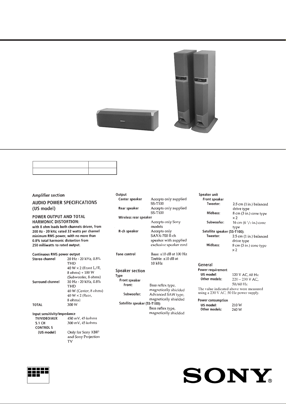
SPECIFICATIONS
US Model
AEP Model
UK Model
E Model
(L-ch) (R-ch)
Photo: Main UnitPhoto: SS-T100
MICROFILM
– Continued on next page –
HOME THEATER ACTIVE SPEAKER SYSTEM
TABLE OF CONTENTS
1. SERVICING NOTES ............................................... 3
2. GENERAL ................................................................... 4
3. DISASSEMBLY ......................................................... 5
4. TEST MODE.............................................................. 8
5. DIAGRAMS
5-1. Note for Printed Wiring Boards
and Schematic Diagrams ................................................ 11
5-2. Printed Wiring Board – Main Board– ........................... 12
5-3. Schematic Diagram – Main Board (1/3) – .................... 13
5-4. Schematic Diagram – Main Board (2/3) – .................... 14
5-5. Schematic Diagram – Main Board (3/3) – .................... 15
5-6. Printed Wiring Boards – FILTER/THERMO/REG/
T2/T1/STANDBY/AC-SW Board – ............................... 16
5-7. Schematic Diagram – FILTER/THERMO/REG/
T2/T1/STANDBY/AC-SW Board – ............................... 17
5-8. Printed Wiring Board – AMP Board – .......................... 18
5-9. Schematic Diagram – AMP Board – ............................. 19
5-10. Printed Wiring Boards
– DISPLAY/LED/KEY Board – ..................................... 20
5-11. Schematic Diagram
– DISPLAY/LED/KEY Board – ..................................... 21
5-12. IC Pin Function Description ........................................... 24
6. EXPLODED VIEWS ................................................ 26
7. ELECTRICAL PARTS LIST ............................... 30
SAFETY-RELATED COMPONENT WARNING!!
COMPONENTS IDENTIFIED BY MARK ! OR DOTTED
LINE WITH MARK ! ON THE SCHEMA TIC DIAGRAMS
AND IN THE PARTS LIST ARE CRITICAL TO SAFE
OPERATION. REPLACE THESE COMPONENTS WITH
SONY PARTS WHOSE PART NUMBERS APPEAR AS
SHOWN IN THIS MANUAL OR IN SUPPLEMENTS PUBLISHED BY SONY.
2
SECTION 1
SERVICING NOTES
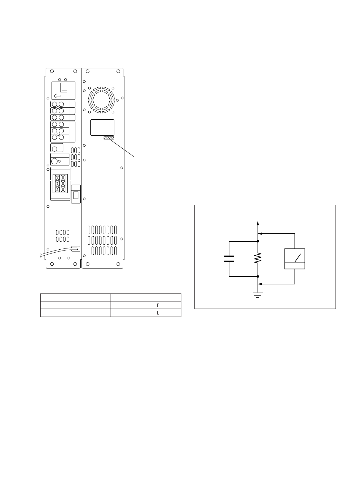
MODEL IDENTIFICATION
– Rear view –
PART No.
SAFETY CHECK-OUT
After correcting the original service problem, perform the following safety check before releasing the set to the customer:
Check the antenna terminals, metal trim, “metallized” knobs,
screws, and all other exposed metal parts for AC leakage.
Check leakage as described below.
LEAKAGE TEST
The A C leaka ge from an y e xposed metal part to earth g round and
from all exposed metal parts to any exposed metal part having a
return to chassis, must not exceed 0.5 mA (500 microamperes).
Leakage current can be measured by any one of three methods.
1. A commercial leakage tester , such as the Simpson 229 or RCA
WT -540A. Follo w the manufacturers’ instructions to use these
instruments.
2. A battery-operated AC milliammeter. The Data Precision 245
digital multimeter is suitable for this job.
3. Measuring the voltage drop across a resistor by means of a
VOM or battery-operated AC voltmeter. The “limit” indication is 0.75 V, so analog meters must have an accurate lowvoltage scale. The Simpson 250 and Sanwa SH-63T rd are e xamples of a passive VOM that is suitable. Nearly all battery
operated digital multimeters that have a 2 V A C range are suitable. (See Fig. A)
To Exposed Metal
Parts on Set
MODEL PART No.
US model 4-217-252-0
EXCEPT US models 4-217-252-2
1.5 k
0.15 µF
Fig. A. Using an AC voltmeter to check AC leakage.
Ω
Earth Ground
AC
voltmeter
(0.75 V)
3
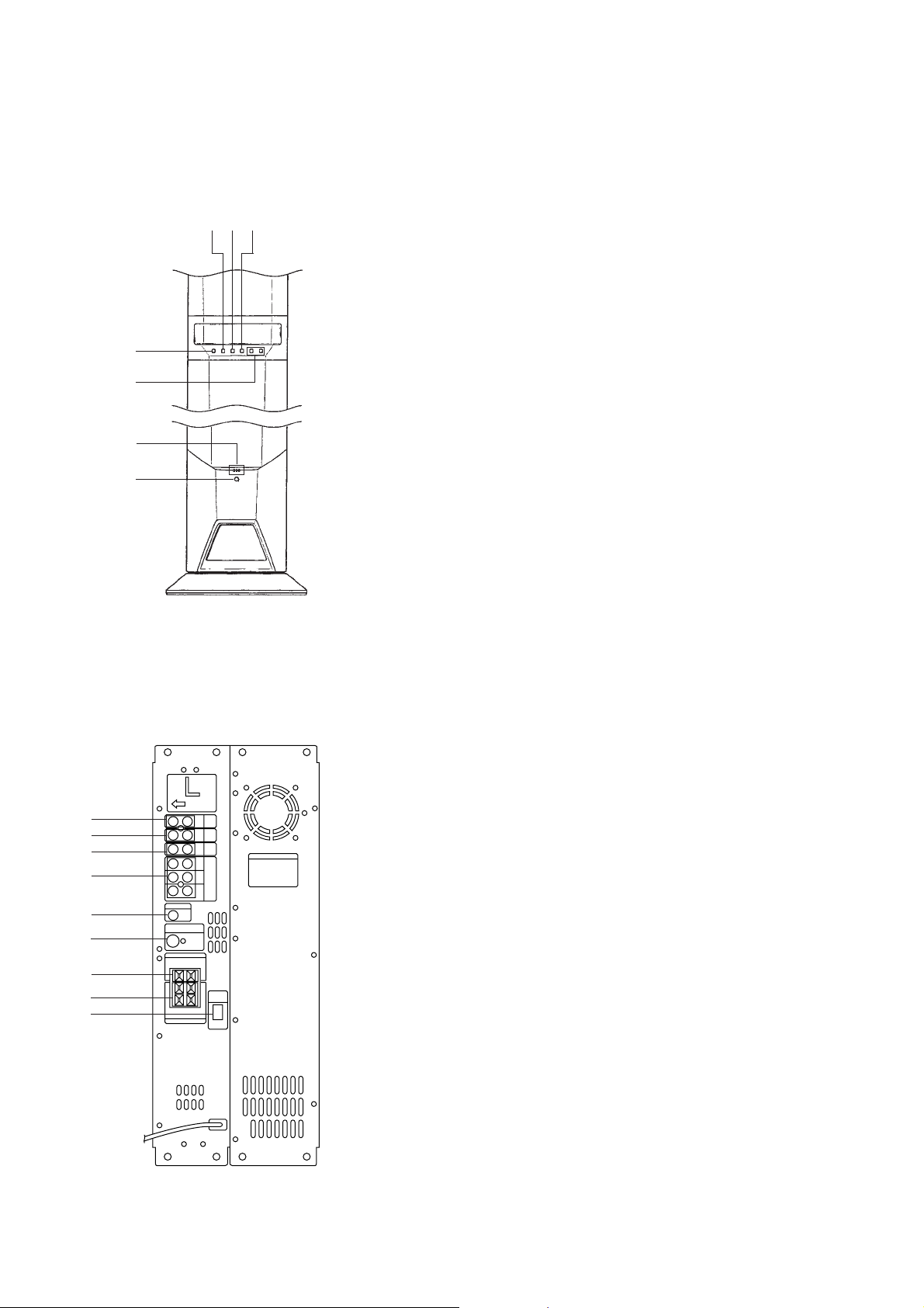
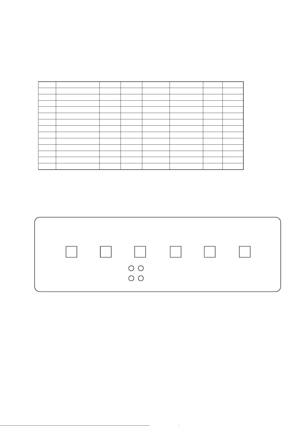
• LOCATION OF CONTROLS
Main Unit (L-ch)
– Front View –
32
1
5
6
7
4
SECTION 2
GENERAL
1 INPUT button
2 SURROUND button
3 CENTER MODE button
4 S. WOOFER button
5 MASTER VOL +/– buttons
6 STANDBY, ON, READY indicators
7 U button
– Rear View –
1
2
3
4
5
6
7
8
9
1 TV IN jack
2 VIDEO IN jack
3 AUX IN jack
4 5.1CH INPUT (FRONT, REAR, WOOFER, CENTER) jack
5 CONTROL S, TV IN jack (US model)
6 WIRELESS REAR SPEAKER jack
7 CENTER SPEAKER terminal
8 REAR SPEAKERS terminal
9 R-ch SPEAKER OUTPUT connector
4
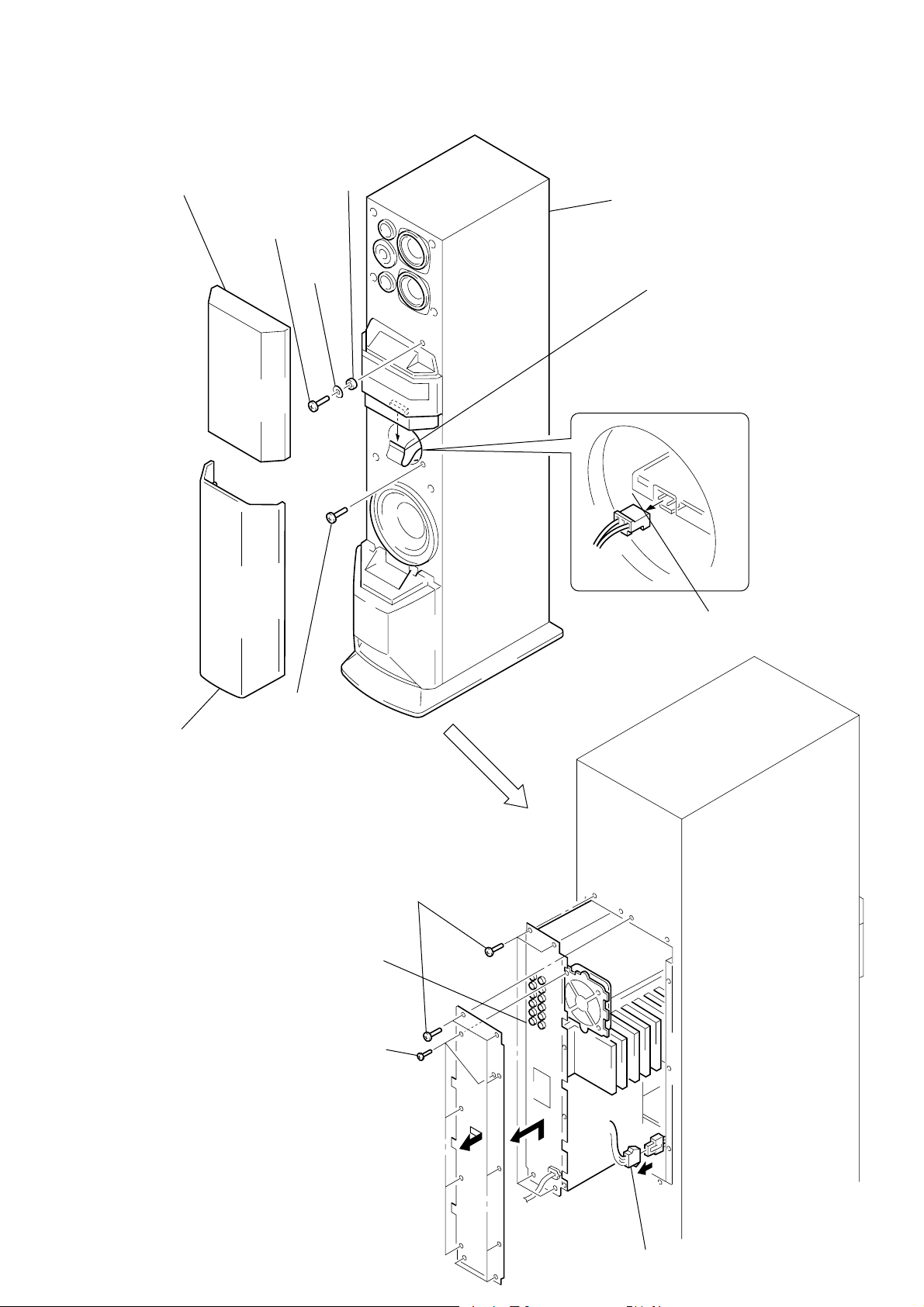
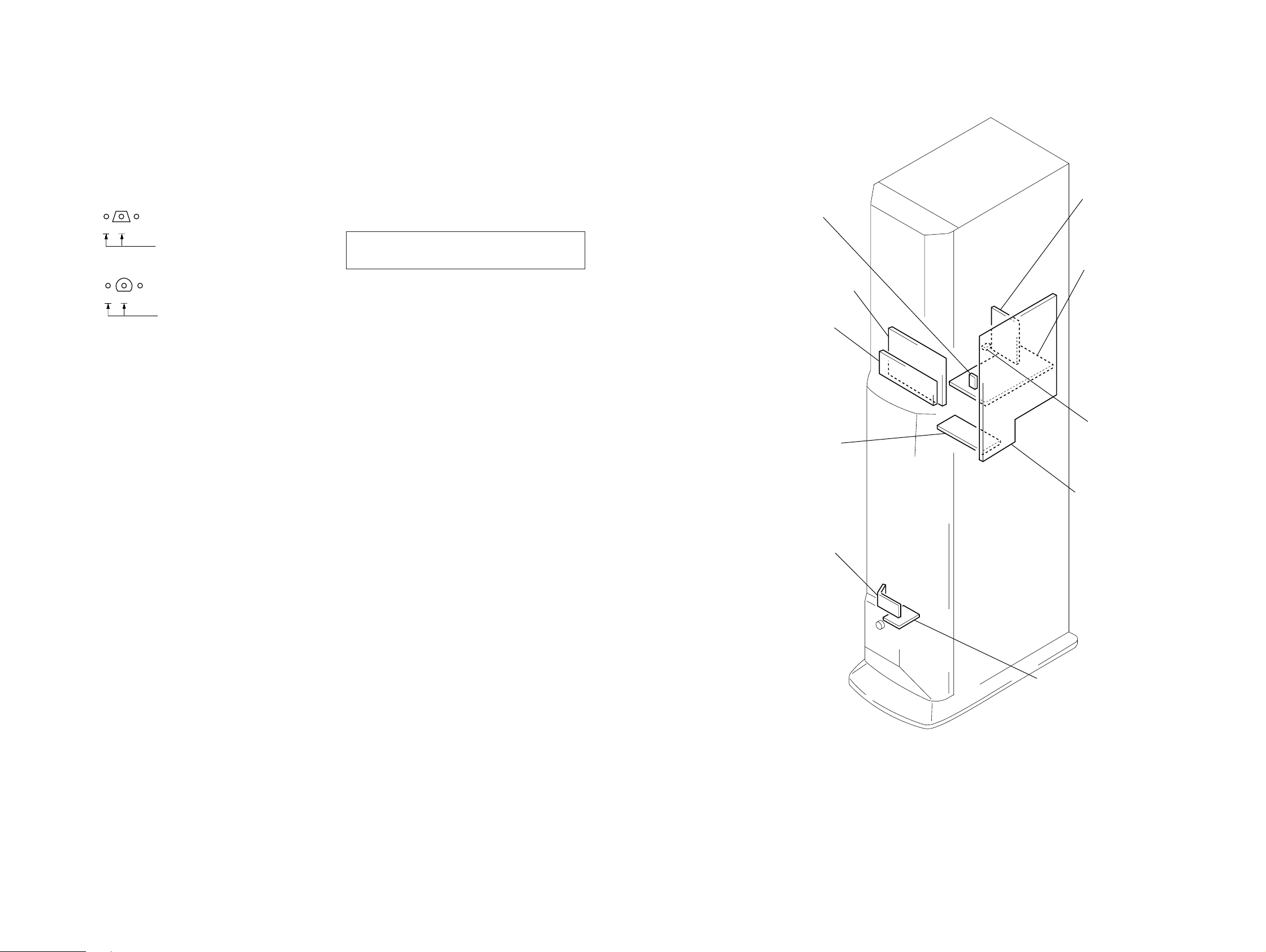
SECTION 3
r
DISASSEMBLY
Note: Follow the disassembly procedure in the numerical order given.
AMPLIFIER SECTION
2
grille frame (A)
ass’y
3
screw
(BVTT4
5 washer
×
25)
4 washer
(BF)
(S)
L-ch speaker section
7
flat wire
(CN503)
1
grille frame (B) ass’y
6
screw
(BVTT4
!£
Remove the amplifier
section in arrow
direction.
!º
five screws
(BVTP3
×
25)
9
eleven screws
(4
×
20)
B
×
8)
8
connecto
(CN907)
!¡
Remove the panel (L/B)
in arrow
A
direction.
A
B
!™
connector
5
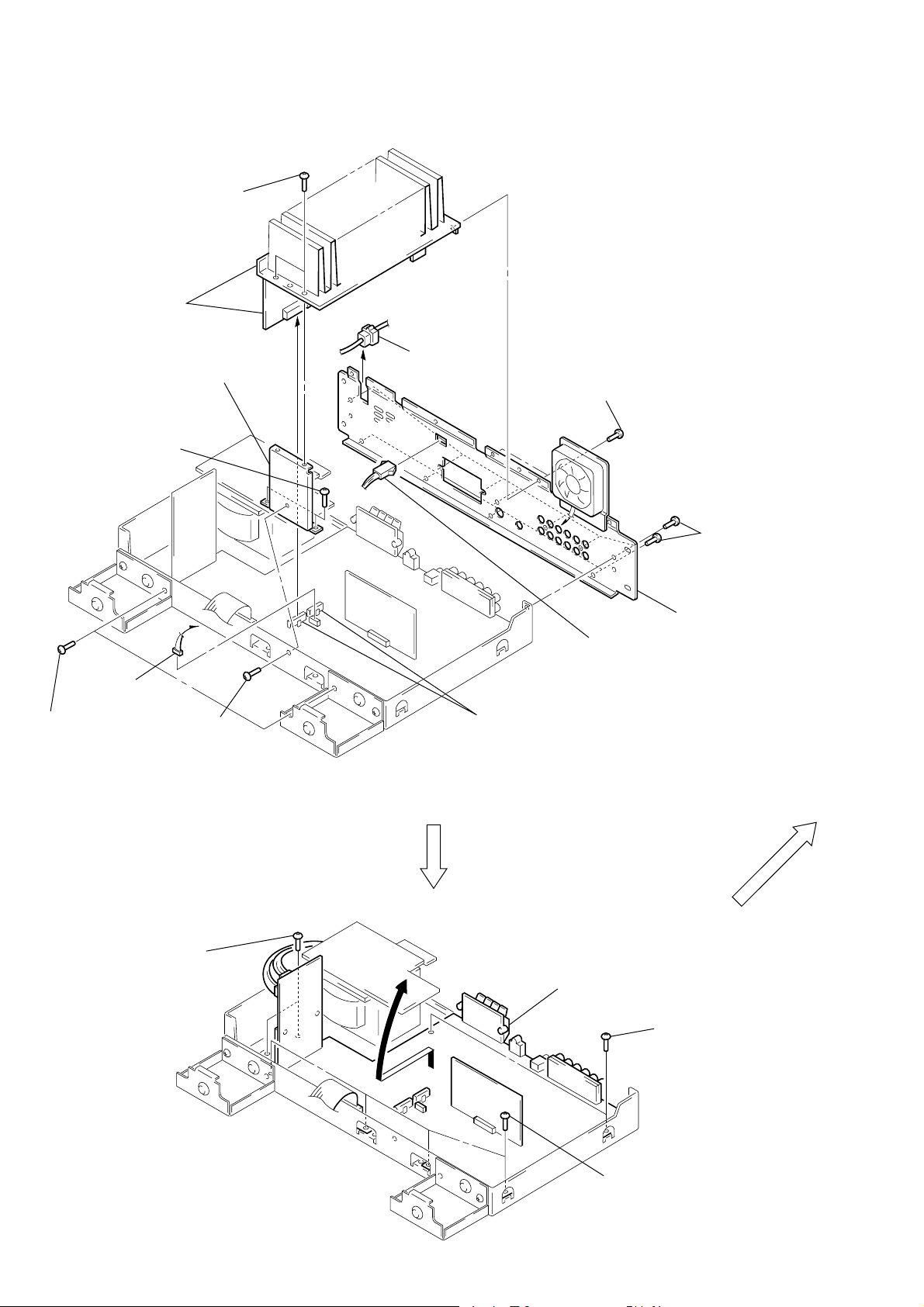
SERVICE POSITION
s
)
1
Remove the amplifier section. (Refer to page 5)
2
two screws
(transistor)
5
heatsink and
AMP board
7
bracket
6
two screws
(BVTP3 × 8)
9
cord bushing
3
two screws
(BVTP3 × 8)
!¡
eleven screw
(BVTP3 × 8)
!£
two screws
(BVTP3 × 8)
8
connector
6
!¢
two screws
(BVTP3
screw
(BVTP3 × 8)
×
8)
A
4
two connectors
(CN601, 603)
!º
connector
Erect the Main board
!∞
in arrow
A
direction.
!™
!¢
two screws
(BVTP3
back panel (L/A)
×
8
!¢
four screws
(BVTP3
×
8)
6
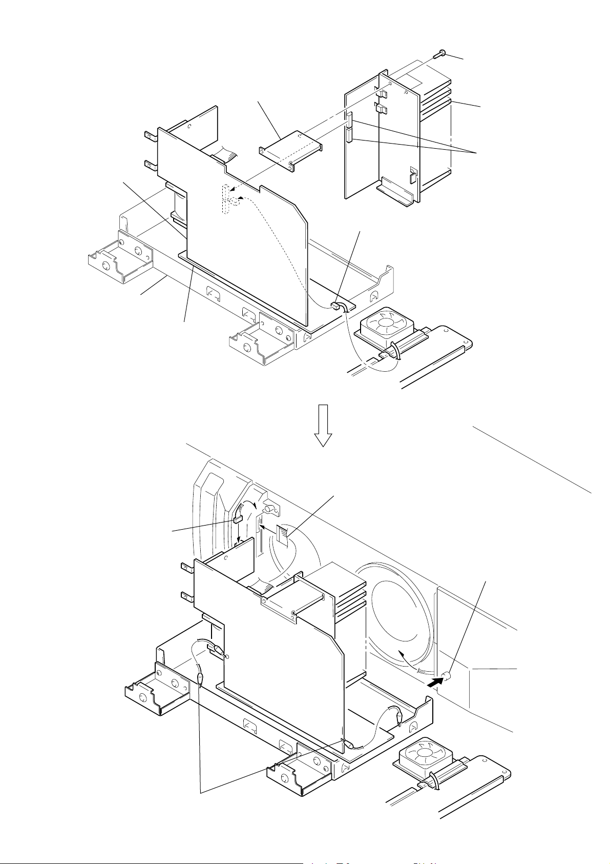
MAIN board
chassis
!§
Insert an insulation sheet
between chassis and
MAIN board.
bracket
!¶
!ª
Connect the fan motor lead wire
to MAIN board connector (CN301).
Attach the bracket
to the heatsink
with two screws.
heatsink
!•
Insert two connectors
(CN601, 603) into
the connectors
(CN301, 911) on
the MAIN board.
@º
Connect the power SW
lead wire to STANDBY
board connector (CN907).
@¡
Connect the flat wire to
DISPLAY board connector (CN503).
@£
Push the power SW.
@™
Connect the MAIN board
and chassis with
two clip wires.
7
SECTION 4
TEST MODE
This set provides four test modes as follows.
1. INPUT CHECK MODE
2. KEY CHECK MODE
3. AMP CHECK MODE
4. DEMONSTRATION MODE
The following describes each test mode in detail.
4-1. INPUT CHECK MODE
Procedure:
1. While pressing the both [S.WOOFER] and [MASTERVOL+] buttons, turn the power ON.
2. Fluorescent indicator tube display “SAVA-700”, after the all lights up, and enter the input check mode.
3. Pressing the [INPUT] button varies the display as follows.
SAVA-700
*********
S.WOOFER *1 S.WOOFER check mode (5.1CH INPUT check mode)
AUX AUX input (SURROUND OFF) check mode
VIDEO VIDEO input (SURROUND OFF) check mode
TV TV input (SURROUND OFF) check mode
AUTO POWER AUTO POWER ON/OFF check mode
*1 Pressing the
maximum, or
Note: In each mode, the volume is muted except for the channels that can be checked.
4. To release the test mode, push back [] button.
[SURROUND] button makes the S.WOOFER level minimum, or the [S.WOOFER] button makes the S.WOOFER level
[CENTERMODE] button returns default.
U
4-2. KEY CHECK MODE
Procedure:
1. Push back [] button to turn the power OFF.
2. Connect the lead wire to TP3 and TP4 on the KEY board.
3. Push [] button to power ON.
4. Let the lead wire short TP3 and TP4.
5. Fluorescent indicator tube display “KEY CHK 700” , and enter the key check mode.
6. Pressing any buttons, the number of button will be displayed on the fluorescent indicator tube.
7. Pressing the f irst button turns on the [READY] LED (red), and the second b utton turns on the [ON] LED (green). T hus, two LEDs light
up alternately each time the buttons are pressed.
INPUT
SURROUND
CENTER MODE
WOOFER
MASTER VOL –
MASTER VOL +
U
U
Button
Button Number
1
2
3
4
5
6
8. After all b uttons are pressed, it will be in the ST ANDBY mode.
Note: If a check failed, the set does not go in STANDBY mode, and you cannot exit from the test mode. In this case, quit the test mode by pushing back
[] button.
U
8
4-3. AMP CHECK MODE
Procedure:
1. Push back [] button to turn the power OFF.
2. Connect the lead wire to TP1 and TP2 on the KEY board.
3. Push [] button to power ON.
4. Let the lead wire connected TP1 and TP2.
5. Fluorescent indicator tube display “AMP CHK 700”, and enter the amp check mode.
6. The check step advances in order as TP1 and TP2 are shorted.
STEP
0
1
2
3
4
5
6
7
8
9
10
11
12
*
*1 The step 12 is the AUTO POWER ON/OFF check.
*2 The step 12 is automatically turned the power OFF in one second, ON when a signal is entered to TV input, and OFF when a signal
input stops.
*3 After the step 12 finished, return the parameters to default values, then turn the power OFF.
7. To release the test mode, push back [] button.
U
U
AMP CHK 700
AMP CHK 1
AMP CHK 2
AMP CHK 3
AMP CHK 4
AMP CHK 5
AMP CHK 6
AMP CHK 7
AMP CHK 8
AMP CHK 9
AMP CHK 10
AMP CHK 11
AMP CHK 12
INPUT
VIDEO
VIDEO
VIDEO
VIDEO
VIDEO
VIDEO
AUX
AUX
5.1
5.1
5.1
5.1
TV
U
VOL
MIN
MAX
MAX
MAX
MAX
MAX
MIN
MAX
MAX
MIN
MAX
MAX
MAX
SW MODE
1
OFF
OFF
OFF
1
2
1
1
1
1
1
1
1
SUR MODE
PRO LOGIC
OFF
PRO LOGIC
GAME
OFF
OFF
PRO LOGIC
PRO LOGIC
–
–
–
–
PRO LOGIC
BASS
0
0
0
0
0
0
0
0
0
0
–5
+5
0
TREBLE
0
0
0
0
0
0
0
0
0
0
–5
+5
0
• Checking Location
– KEY Board (Conductor Side) –
S505 S506 S502
S504 S503 S501
TP3 TP2
TP4TP1
9
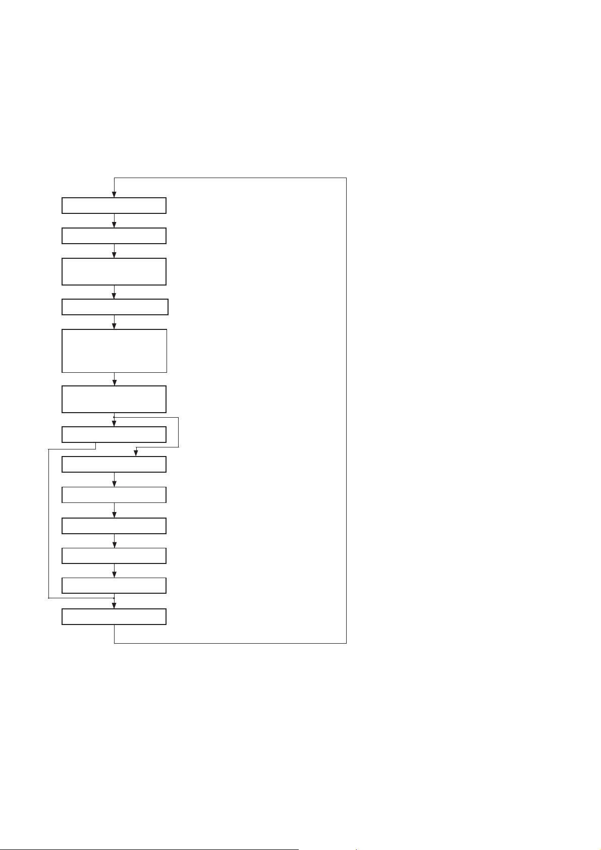
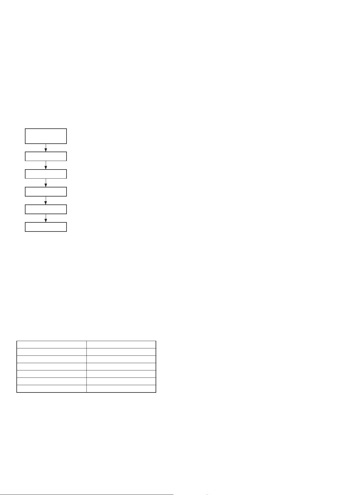
4-4. DEMONSTRATION MODE
1. Entering the demonstration mode
• Press the [INPUT] and [MASTERVOL+] buttons simultaneously to start demonstration mode.
• When the set goes in demonstration mode, the [ON] LED (green) blinks, and the [STANDBY] and [READY] LEDs (red) light up.
• The sequence during the demonstration mode is following as bellow.
Notes:1. In the demonstration mode, only the [INPUT], [MASTERVOL], and [S.WOOFER] buttons are active.
2. The operation with remote commander is disabled.
Demonstration mode sequence:
@@@@@@@@@
@ H E L L O @
WELCOME TO SAVA *1
SOUND SYSTEM
I AM SAVA-700 *1
MY FEATURES ARE 4
INPUTS AND 5 *1
SURROUND MODE
LISTEN TO *1
MY SOUND
5.1 INPUT
5.1 CH IN OTHER INPUT
PRO LOGIC *2
C.STUDIO *2
*1 First seven characters are dis-
played, then eighth and subsequent characters are displayed.
HALL *2
(Characters run on the display)
*2 Displayed for 5 seconds.
STUDIUM *2
GAME *2
THANK YOU *2
Note: 1 The demonstration mode operates with the input, and volume position selected last.
2 The input and volume are variable even during demonstration mode.
2. Releasing the demonstration mode
• To release the demonstration mode, push back [] button.
U
10
SECTION 5
DIAGRAMS
5-1. NOTE FOR PRINTED WIRING BOARDS AND SCHEMATIC DIAGRAMS
Note on Printed Wiring Board:
• X : parts extracted from the component side.
• Y : parts extracted from the conductor side.
• p : parts mounted on the conductor side.
• b : Pattern from the side which enables seeing.
(The other layers' patterns are not indicated.)
• Indication of transistor.
Q
B
CE
These are omitted.
Q
B
CE
These are omitted.
Note on Schematic Diagram:
• All capacitors are in µF unless otherwise noted. pF: µµF
50 WV or less are not indicated except for electrolytics
and tantalums.
• All resistors are in Ω and 1/
specified.
¢
•
• 2 : nonflammable resistor.
• 5 : fusible resistor.
• C : panel designation.
Note: The components identified by mark ! or dotted line
• U : B+ Line.
• V : B– Line.
• Voltages and waveforms are dc with respect to ground
• Voltages are taken with a VOM (Input impedance 10 MΩ).
• Waveforms are taken with a oscilloscope.
• Circled numbers refer to waveforms.
• Signal path.
: internal component.
with mark ! are critical for safety.
Replace only with part number specified.
under no-signal conditions.
no mark : AUDIO
Voltage var iations may be noted due to normal production tolerances.
Voltage var iations may be noted due to normal production tolerances.
F : AUDIO
4
W or less unless otherwise
• Circuit Boards Location
FILTER board
REG board
AMP board
DISPLAY board
KEY board
THERMO board
STANDBY board
LED board
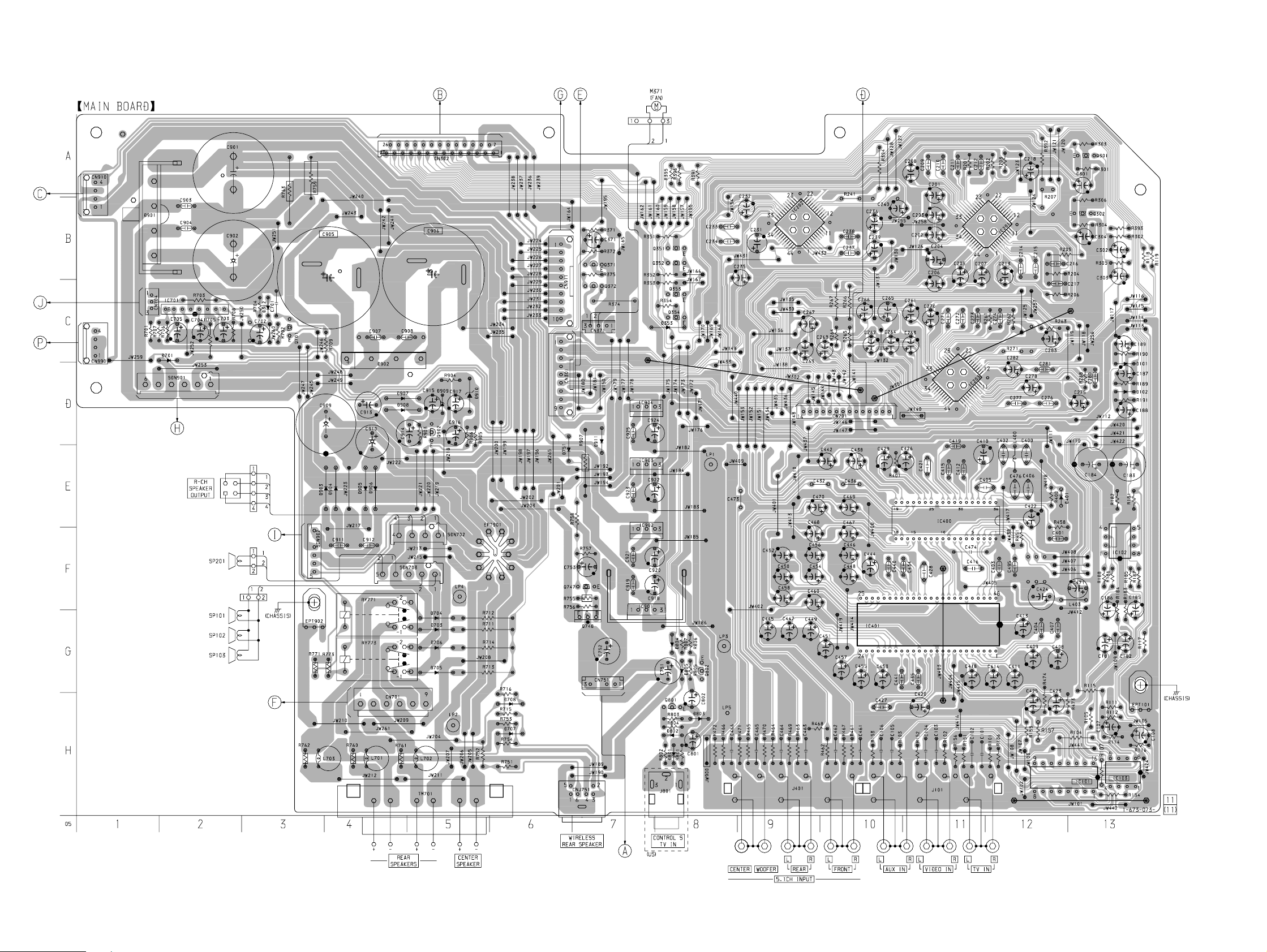
MAIN board
AC-SW board
– L-ch speaker section –
1111
SAV A-700/SS-T100
5-2. PRINTED WIRING BOARD – MAIN Board – • See page 11 for Circuit Boards Location.
(Page 16)
(Page 16)
(Page 16)
(Page 20)
(Page 18)
(Page 18)
(Page 16)
(Page 16)
(Page 16)
(Page 18)
(Page 16)
1212
 Loading...