

Sony SS-RC301 User Manual

FM Stereo
FM-AM Receiver
3-866-659-11(1)
Operating Instructions
STR-DE335
^SfR-SE391
1999 by Sony Corporalion

WARNING
To prevent fire or shock
hazard, do not expose
the unit to rain or
moisture.
RBKOPeJCTNCSHOCK 1 / I \
I I / ! \
A
CAimON: TO KOUCe TT« MSK of El£CTniC SHOCK.
00 NOT WMOVC COVER KM SACK)
HO USCn-SERMCCAOLE FARTS wsne
A
This symbol is intended to alert the user
to the presence of uninsulated
"dangerous voltage" within the
product's enclosure that may be of
sufficient magnitude to constitute a risk
of electric shock to persons.
A
This symbol is intended to alert the user
to the presence of important operating
and maintenance (servicing)
instructions in the literature
accompanying the appliance.
IMPORTANT
This equipment has been tested and
found to comply with the limits for a
Class B digital device, pursuant to Part
15 of the FCC Rules.
These limits are designed to provide
reasonable protection against harmful
interference in a residential installation.
This equipment generates, uses, and can
radiate radio frequency energy and, if
not installed and used in accordance
with the instructions, m^y cause
harmful interference to radio
communications. However, there is no
guarantee that interference will not
occur in a particular installation. If this
equipment does cause harmful
interference to radio or television
reception, which can be determined by
turning the equipment off and on, the
user is encouraged to try to correct the
interference by one or more of the
following measures:
- Reorient or relocate the receiving
antenna,
- Increase the separation between the
equipment and receiver.
- Connect the equipment into an outlet
on a circuit different from that to
which the receiver is connected.
- Consult the dealer or an experienced
radio/TV technician for help.
CAUTION
You are cautioned that any change or
modifications not expressly approved in
this manual could void your authority
to operate this equipment.
Note to CATV system installer
This reminder is provided to call the
CATV system installer's attention to
Article 820-40 of the NEC that provides
guidelines for proper grounding and, in
particular, specifies that the cable
ground shall be connected to the
grounding system of the building, as
close to the point of cable entry as
practical.
Owner's record
The model and serial numbers are
located on the rear of the unit. Record
the serial number in the space provided
below. Refer to them whenever you call
upon your Sony dealer regarding this
product.
Model No. STR-DE335/STR-SE391
Serial No...
Precautions
On safety
• Should any solid object or liquid fall
into the cabinet, unplug the receiver
and have it checked by qualified
personnel before operating it any
further.
On power sources
• Before operating the receiver, check
that the operating voltage is identical
with your local power supply. The
operating voltage is indicated on the
nameplate at the rear of the receiver.
• The receiver is not disconnected from
the AC power source (MAINS) as
long as it is connected to the wall
outlet, even if the receiver itself has
been turned off.
• If you are not going to use the
receiver for a long time, be sure to
disconnect the receiver from the wall
outlet. To disconnect the AC power
cord, grasp the plug itself; never pull
the cord.
• One blade of the plug is wider than
the other for the purpose of safety
and will fit into the wall outlet only
one way. If you are unable to insert
the plug fully into the outlet, contact
your dealer.
• Should the AC power cord need to be
changed, have it done at a qualified
service shop only.
On placement
• Place the receiver in a location with
adequate ventilation to prevent heat
build-up and prolong the life of the
receiver.
• Do not place the receiver near heat
sources, or in a place subject to direct
sunlight, excessive dust or
mechanical shock,
• Do not place anything on top of the
cabinet that might block the
ventilation holes and cause
malfunctions.
On operation
• Before connecting other components,
be sure to turn off and unplug the
receiver.
On cleaning
• Clean the cabinet, panel and controls
with a soft cloth slightly moistened
with a mild detergent solution. Do
not use any type of abrasive pad,
scouring powder or solvent such as
alcohol or benzine.

For detailed safety precautions, see the
"IMPORTANT SAFEGUARDS" leaflet.
If you have any question or problem
concerning your receiver, please
consult your nearest Sony dealer.
About This Manual
The instructions in this manual are for
models STR-DE335 and STR-SE391.
Check your model number by looking
at the upper right corner of the front
panel or lower right corner of the
remote. In this manual, the STR-DE335
is the model used for illustration
purposes, any difference in operation is
clearly indicated in the text, for
example, "STR-DE335 only".
Type of differences
^^^^Model
Feature
PHONO
VIDEO
MONITOR
Conventions
The instructions in this manual describe
the controls on the receiver. You can
also use the controls on the remote if
they have the same or similar names as
those on the receiver.
• A "Quick Reference Guide" is
supplied on page 26.
• The "Remote Button Descriptions"
section on page 25 provides an
overview of the remote buttons.
• The following icons are used in this
manual:
Indicates that you can use only
the remote to do the task,
sjjb. Indicates hints and tips for
i making the task easier.
DE335 SE391
•
Table of contents
Getting Started
Unpacking 4
Hookup Overview 4
Antenna Hookups 5
Audio Component Hookups 6
Video Component Hookups 6
Speaker System Hookups 8
AC Hookups 10
Before You Use Your Receiver 10
Receiver Operations
Selecting a Component 11
Receiving Broadcasts 13
Presetting Radio Stations 14
Recording 15
Using the Sleep Timer 15
Using Surround Sound
Choosing a Sound Field 16
Getting the Most Out of Dolby Pro Logic Surround Sound 17
Additional Information
Troubleshooting 20
Specifications 21
Glossary 22
Index 23
Rear Panel Descriptions 24
Remote Button Descriptions 25
Quick Reference Guide 26
This receiver has the Dolby Surround
system.
Manufactured under license from Dolby
Laboratories Licensing Corporation.
"Dolby," "Pro Logic" and the double-D
symbol DO are trademarks of Dolby
Laboratories Licensing Corporation.
*
Getting Started
Unpacking
Check that you received the following items with the
receiver;
• FM wire antenna (1)
• AM loop antenna (1)
• Remote commander (remote) (1)
• Size AA (R6) batteries (2)
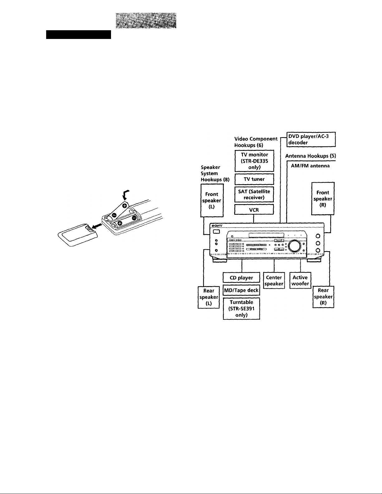
Inserting batteries into the remote
Insert two size AA (R6) batteries in accordance with
the + and - markings on the battery compartment.
When using the remote, point it at the remote sensor I
on the receiver.
Hookup Overview
The receiver allows you to connect and control the
following audio/video components. Follow the
hookup procedures for the components that you want
to connect to the receiver on the pages specified. To
learn the locations and names of each jack, see "Rear
Panel Descriptions" on page 24.
'O' When to replace batteries
Under normal use, the batteries should last for about 6
months. When the remote no longer operates the
receiver, replace both batteries with new ones.
Notes
• Do not leave the remote in an extremely hot or humid
place.
• Do not use a new battery with an old one.
• Do not expose the remote sensor to direct sunlight or
lighting apparatuses. Doing so may cause a malfunction.
• If you don't use the remote for an extended period of time,
remove the batteries to avoid possible damage from
battery leakage and corrosion.
Audio Component
Hookups (6)
Before you get started
• Turn off the power to all components before making
any connections.
• Do not connect the AC power cords until all of the
connections are completed.
• Be sure to make connections firmly to avoid hum
and noise.
• When connecting an audio/video cable, be sure to
match the color-coded pins to the appropriate jacks
on the components: Yellow (video) to Yellow; White
(left, audio) to White; and Red (right, audio) to Red.
Getting Started
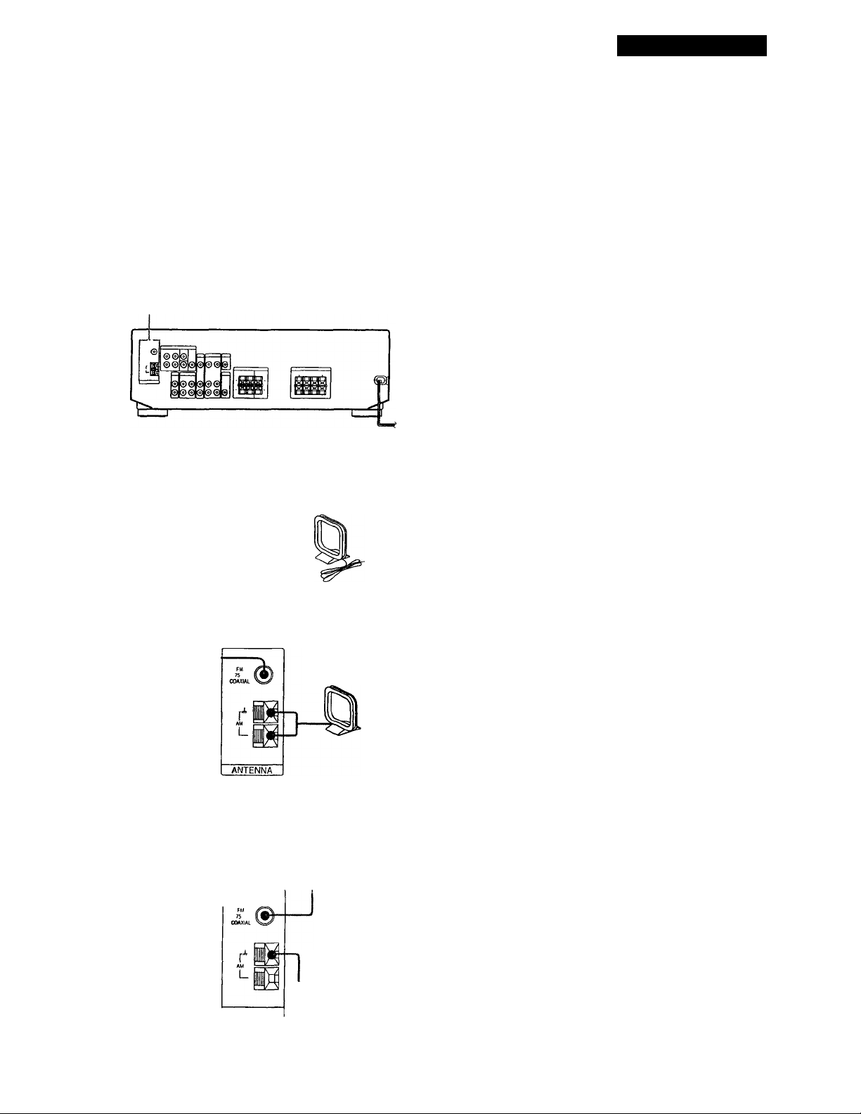
Antenna Hookups
Overview
This section describes how to connect AM and FM
antennas to the receiver. If you want to receive radio
broadcasts with the receiver, complete these
connections first, then go to the following pages.
For specific locations of the terminals, see the
illustration below.
ANTENNA
What antennas will I need?
• FM wire antenna
(supplied) (1)
AM loop antenna
(supplied) (1)
Q If you have poor AM reception
Connect a 20 to 50 ft. (6 to 15-meter) insulated wire (not
supplied) to the AM antenna terminal in addition to the
AM loop antenna. Try to extend the wire outdoors and
keep it horizontal.
Connecting a ground wire
If you connect the receiver to an outdoor antenna,
ground it against lightning as shown in the illustration
in the left column. To prevent a gas explosion, do not
connect the ground wire to a gas pipe.
Note (STR-SE391 only)
Do not use the SIGNAL GND ih terminal for grounding the
receiver.
Where do i go next?
If you want to connect other components, go on to the next
section. If you're only planning to use the receiver to listen
to the radio, go to "Speaker System Hookups" on pages 8
and 9.
Hookups
FM wire antenna
After connecting
the wire
antenna, keep it
as horizontal as
possible.
' If you have poor FM reception
Use a 75-ohm coaxial cable (not supplied) to connect the
receiver to an outdoor FM antenna as shown below.
Receiver
Receiver
ANTENNA
AM loop antenna
FM outdoor antenna
Ground wire
(not supplied)
♦
to ground
Getting Started
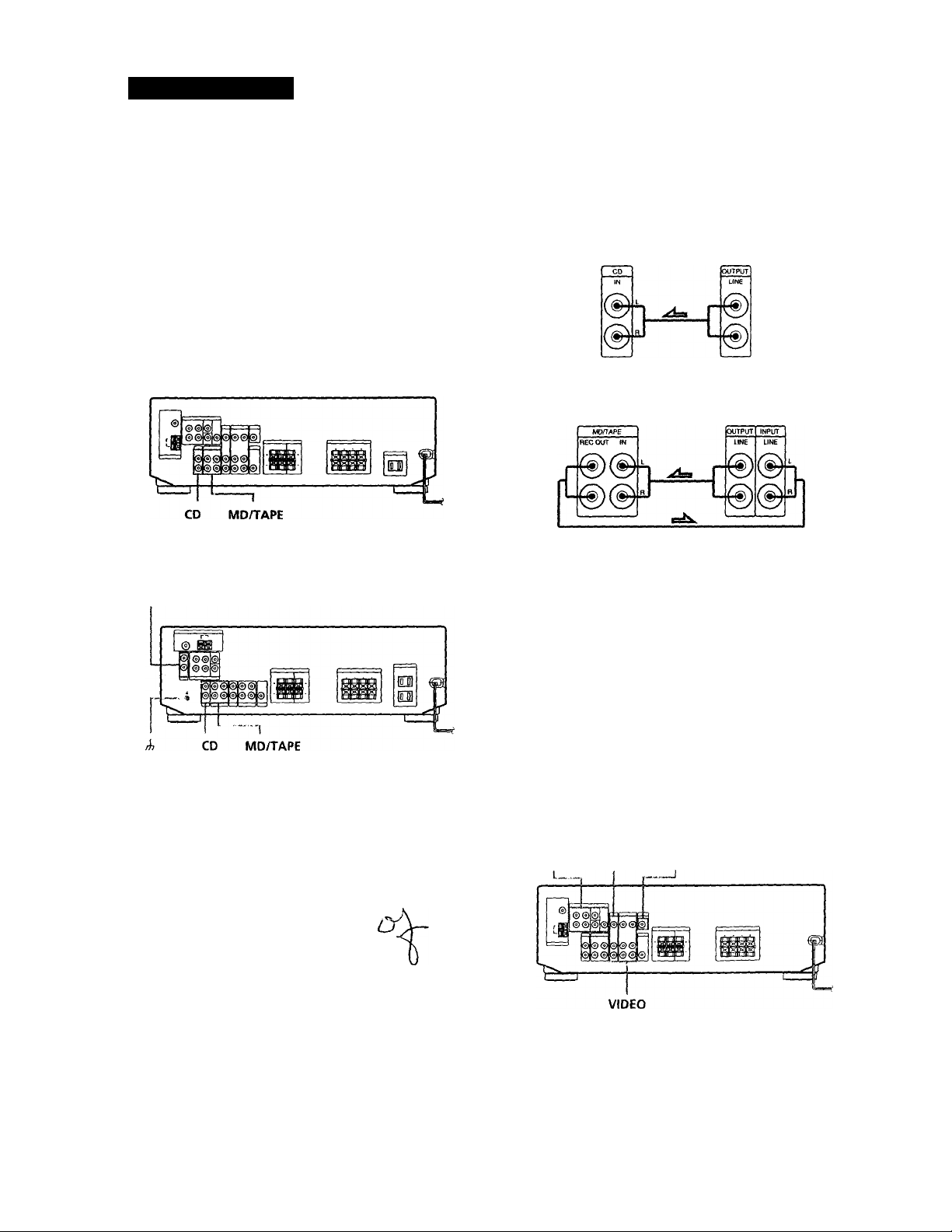
Audio Component Hookups
Hookups
The arrow =
indicates signal flow.
Overview
This section describes how to connect your audio
components to the receiver. If you want to use the
receiver as an amplifier, complete these connections.
For specific locations of the jacks, see the illustration
below.
STR-DE335 only
STR-SE391 only
PHONO
CD player
Receiver
MD recorder or Tape deck
Receiver MD recorder or Tape deck
CD player
Where do I go next?
Go on to the next section to connect video components to
enjoy surround sound when loatching!listening to TV
programs or video tapes.
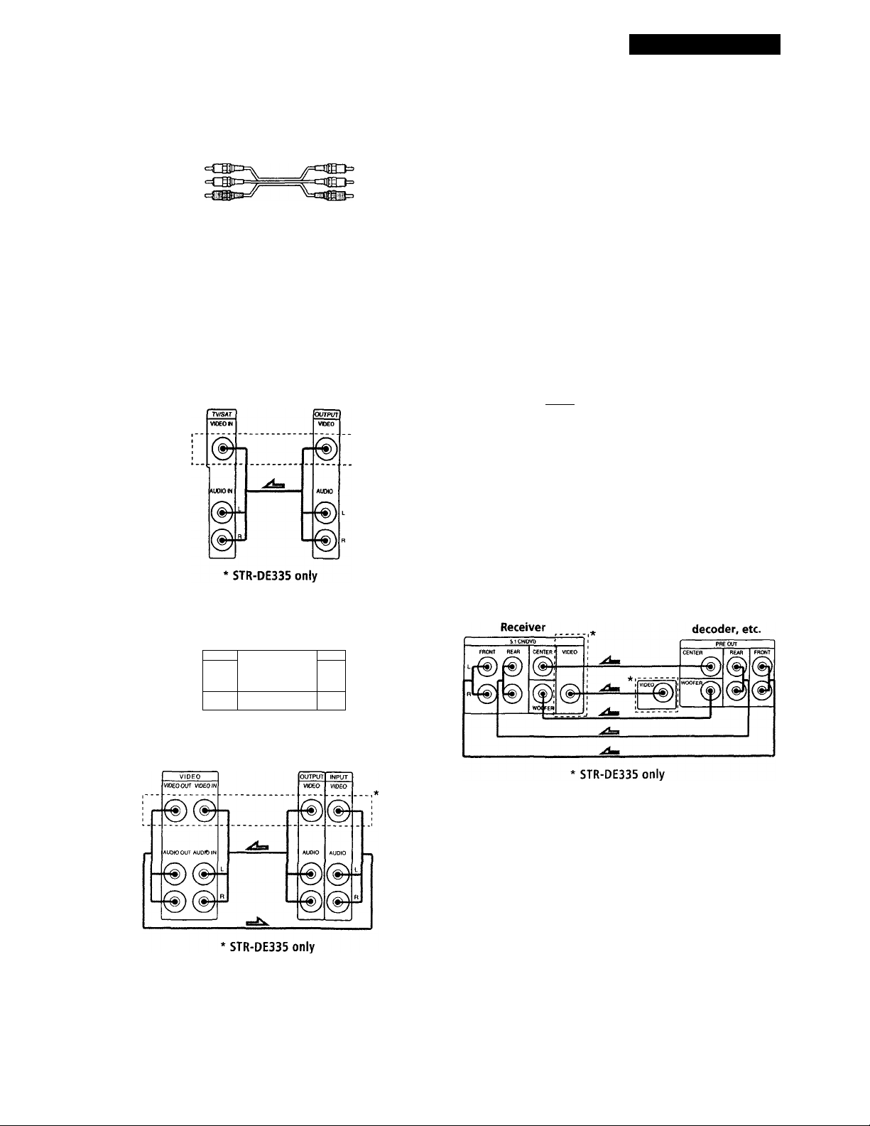
Video Component Hookups
Overview
What cables will I need?
Audio cords (not supplied) (1 for each CD player or
turntable; 2 for each MD recorder or tape deck)
White (L)
Red (R)
i
White (L)
Red (R)
bj.R,
This section describes how to connect video
components to the receiver. For specific locations of the
jacks, see the illustration below.
5.1 CH/DVD TV/SAT MONITOR (STR-DE335 only)
Getting Started
What cables will I need?
• Audio/video cable (not supplied) (1 for each TV tuner or
Satellite receiver; 2 for the VCR)
Yellow
White (L)
Red (R)
Yellow
White (L)
Red (R)
Video cable (not supplied) (1 for a TV monitor)
Yellow Yellow
Hookups
The arrow ■=
TV/SAT
indicates signal flow.
TV tuner or Satellite
Receiver
receiver
Use the function buttons (TV/SAT CD, MD/TAPE etc)
to select the VIDEO AUDIO OUT signal. You can record
this audio signal by connecting a recording component
such as a cassette deck (to the VIDEO AUDIO OUT
jack).
DVD player/AC-3 decoder
What cables will I need?
• Audio cable (not supplied) (1 for each 5.1 CH/DVD
FRONT and REAR jacks)
White (L)
Red (R)
White (L)
Red (R)
Monaural audio cable (not supplied) (1 for each 5.1
CH/DVD CENTER and WOOFER jacks)
Black cjTBte Black
Video cable (not supplied) (1 for the 5.1 CH/DVD
VIDEO IN jack) (STR-DE335 only)
Yellow <41310= 3113= Yellow
MONITOR (STR-DE335 only)
Receiver
MONITOR
VIDEO OUT
VCR
Receiver
TV monitor
INPUT
VIDEO
VCR
You can play decoded Dolby Digital AC-3 soundtracks
through the speakers connected to the amplifier.
If you have a Dolby Digital AC-3 decoder you can
amplify a decoded Dolby Digital AC-3 soundtrack with
the following connections.
Dolby Digital AC-3
Where do I go next?
Go on to the next section to connect the speakers.
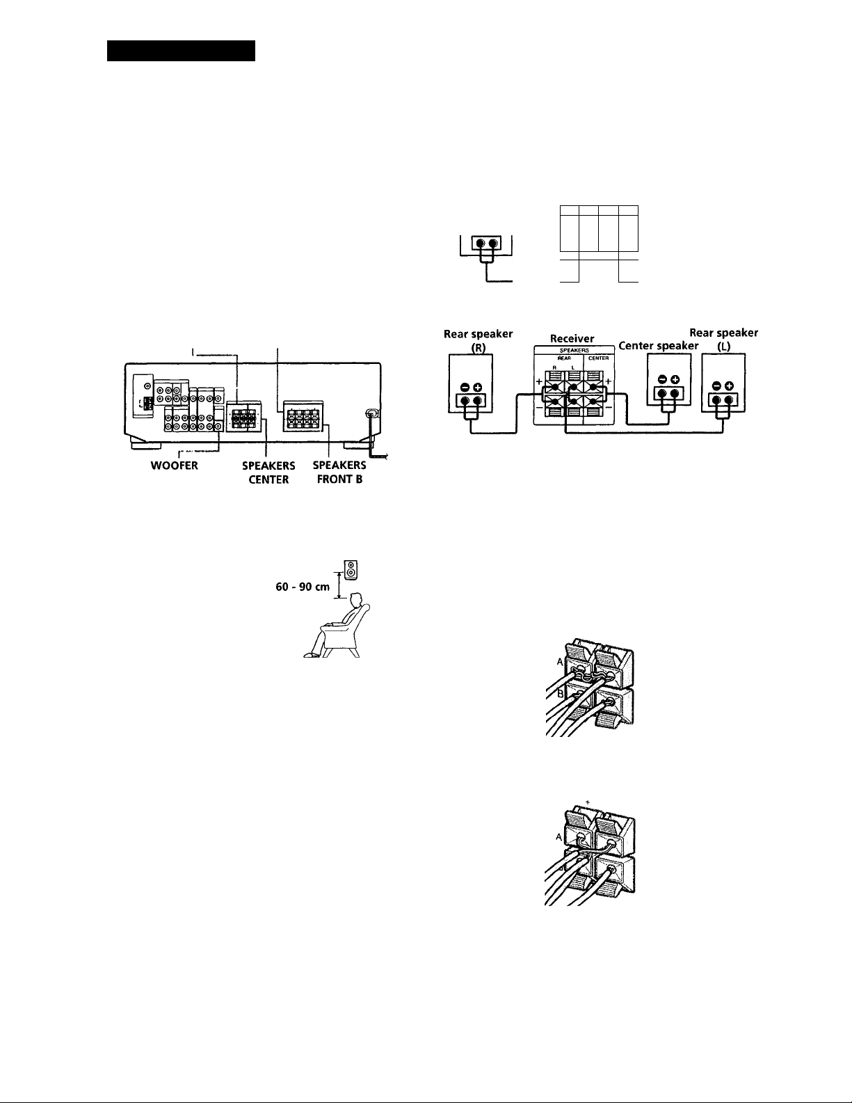
Getting Started
Speaker System Hookups
Hookups
Front Speakers
Overview
This section describes how to connect your speakers to
the receiver. Although front (left and right) speakers
are required, center and rear speakers are optional.
Adding center and rear speakers will enhance the
surround effects. Connecting an active woofer will
increase bass response. For specific locations of the
terminals, see the illustration below.
SPEAKERS REAR
For optimum surround sound effect, place your
speakers as shown below.
SPEAKERS
FRONT A
Rear speaker
Front speaker
(R)
eo
Receiver
m
N
■r M
o o
Front speaker
(L)
OO
W
Rear and center speakers
To avoid short-circuiting the speakers
Short-circuiting of the speakers may damage the
receiver. To prevent this, make sure to take the
following precautions when cormecting the speakers.
Make sure the stripped ends of each speaker cord does
not touch another speaker terminal or the stripped end
of another speaker cord.
45“
□
What cords will i need?
Speaker cord (not supplied) (1 for each speaker)
(+)
(-)
Twist the stripped ends of the cord about 2/3 inch (15 mm).
Be sure to match the speaker cord to the appropriate
terminal on the components; + to + and - to -. If the cords
are reversed, the sound will be distorted and will lack bass.
(+)
(-)
Examples of poor conditions of the speaker cord:
Stripped speaker cord is touching another speaker
terminal.
R _
Stripped cords are touching each other due to excessive
removal of insulation
8
 Loading...