

Sony SSMS-815, SAVE-812-ED, SAVE-815-ED, SAWMS-815 Service manual
SA-VE812ED/VE815ED/
WMS815/SS-MS815
SERVICE MANUAL
The SA-VE812ED system consists of one unit
of SA-WMS815 and two units of SS-MS815.
The SA-VE815ED system consists of one unit
of SA-WMS815 and five units of SS-MS815.
For the U.S. model
AUDIO POWER SPECIFICATIONS
POWER OUTPUT AND TOTAL
HARMONIC DISTORTION :
with 8 Ω loads both channels driven, from 20 - 150Hz; rated
150 W per channel minimum RMS power, with no more
than 0.8% total harmonic distortion from 250 mW to rated
output.
SS-MS815 (front, center, and rear speakers)
Speaker system 2 way, magnetically shielded
Speaker units
Tweeter : 1.9 cm (
Woofer : 5 cm (
Enclosure type Bass reflex
Rated impedance 8 Ω
Power handling capacity
Maximum input power: 140 W
Sensitivity level 87 dB (1W, 1m)
Frequency range 120 Hz - 70,000 Hz
Dimensions (w/h/d)
When attached speaker grilles:
When attached to supplied speaker stand:
3
/4 in.), dome type
2 in.) × 2, balanced drive
type
Approx. 86 × 169 × 130 mm
1
(3
/2 × 63/4 × 51/8 in.) each
Approx. 96 × 207 × 141 mm
(37/8 × 81/4 × 55/8 in.) each,
(Front (and rear)speakers)
Approx. 169 × 131 × 144 mm
(63/4 × 51/4 × 53/4 in.),
(Center speaker: pointed upwards)
Approx. 169 × 118 × 141 mm
(63/4 × 43/4 × 55/8 in.),
(Center speaker: pointed
downwards):
Mass
SA-WMS815 (subwoofer)
System
Speaker system Active subwoofer, magnetically
Speaker unit Woofer : 20 cm (8 in.),
Enclosure type Advanded SAW type
Continuous RMS power output
Reproduction frequency range
Inputs
LINE IN (input pin jack)
SPEAKER IN (input terminals)
Outputs
LINE OUT (output pin jack)
SPEAKER OUT (output terminals)
General
Power requirements
European models : 220 - 230 V AC, 50/60 Hz
Other models : 120 V AC, 60 Hz
Power consumptions 130 W
Dimensions (w/h/d) Approx. 230 × 395 × 495 mm
Mass Approx. 17.5 kg
Photo : SA-WMS815 Photo : SS-MS815
SPECIFICATIONS
When attached speaker grilles:
When attached to supplied speaker stand:
Approx. 1.3 kg (2lb 14oz) each
Approx. 1.4 kg (3lb 1oz) each,
(Front (and rear) speakers)
Approx. 1.4 kg (3lb 1oz), (Center
speaker)
shielded
cone type
150 W (8 Ω, 20 - 150 Hz, 0.8 %
THD)
24 Hz - 150 Hz
1
/8 × 155/8 × 191/2 in.), including
(9
front grille
(37 lb 9 oz)
US Model
Canadian Model
AEP Model
UK Model
E Model
Supplied accessories
SA-VE815ED
Speaker stands (for the front and rear speakers) (4)
Speaker stand (for the center speaker) (1)
Screws (for the speaker stands) (10)
Washers (for the speaker stands) (10)
Plates (for the front and rear speaker stands) (4)
Speaker grilles (5)
Audio connecting cord (1)
Speaker connecting cords, 2.5 m (8 ft
Speaker connecting cords, 10 m (32 ft
SA-VE812ED
Speaker stands (for the front speakers) (2)
Screws (for the speaker stands) (4)
Washers (for the speaker stands) (4)
Plates (for the front speaker stands) (2)
Speaker grilles (2)
Audio connecting cord (1)
Speaker connecting cords, 2.5 m (8 ft
Design and specifications are subject to change
without notice
21/2 in.) (5)
93/4 in.) (2)
21/2 in.) (4)
MICRO SATELLITE SYSTEM
SAFETY CHECK-OUT
After correcting the original service problem, perform the
following safety checks before releasing the set to the customer:
Check the antenna terminals, metal trim, “metallized” knobs, screws,
and all other exposed metal parts for A C leakage. Check leakage as
described below.
LEAKAGE
The AC leakage from any exposed metal part to earth ground
and from all exposed metal parts to any exposed metal part having
a return to chassis, must not exceed 0.5 mA (500 microamperes).
Leakage current can be measured by any one of three methods.
1. A commercial leakage tester, such as the Simpson 229 or RCA
WT -540A. Follo w the manufacturers’ instructions to use these
instruments.
2. A battery-operated AC milliammeter. The Data Precision 245
digital multimeter is suitable for this job.
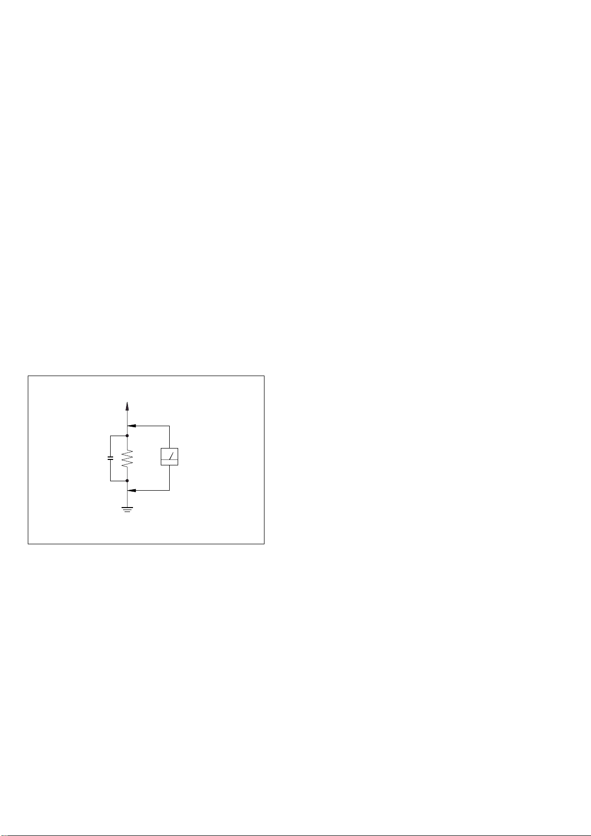
3. Measuring the voltage drop across a resistor by means of a
VOM or battery-operated A C voltmeter . The “limit” indication
is 0.75 V, so analog meters must have an accurate lo w-v oltage
scale. The Simpson 250 and Sanwa SH-63Trd are e xamples of
a passive VOM that is suitable. Nearly all battery operated
digital multimeters that have a 2V AC range are suitable. (See
Fig. A)
To Exposed Metal
Parts on Set
AC
0.15 µF
Fig. A. Using an AC voltmeter to check AC leakage.
1.5 kΩ
Earth Ground
Voltmeter
(0.75 V)
SAFETY-RELATED COMPONENT WARNING!!
COMPONENTS IDENTIFIED BY MARK ! OR DOTTED LINE WITH
MARK ! ON THE SCHEMATIC DIAGRAMS AND IN THE PARTS
LIST ARE CRITICAL TO SAFE OPERATION. REPLACE THESE
COMPONENTS WITH SONY PARTS WHOSE PART NUMBERS
APPEAR AS SHOWN IN THIS MANUAL OR IN SUPPLEMENTS
PUBLISHED BY SONY.
2
ATTENTION AU COMPOSANT AYANT RAPPORT
À LA SÉCURITÉ!
LES COMPOSANTS IDENTIFÉS PAR UNE MARQUE ! SUR LES
DIAGRAMMES SCHÉMATIQUES ET LA LISTE DES PIÈCES SONT
CRITIQUES POUR LA SÉCURITÉ DE FONCTIONNEMENT. NE
REMPLACER CES COMPOSANTS QUE PAR DES PIÈSES SONY
DONT LES NUMÉROS SONT DONNÉS DANS CE MANUEL OU
DANS LES SUPPÉMENTS PUBLIÉS PAR SONY.
SECTION 1
B
These are omitted.
CE
Q
T
d
GENERAL
SA-VE812ED/VE815ED/WMS815/SS-MS815
SECTION 2
DIAGRAMS
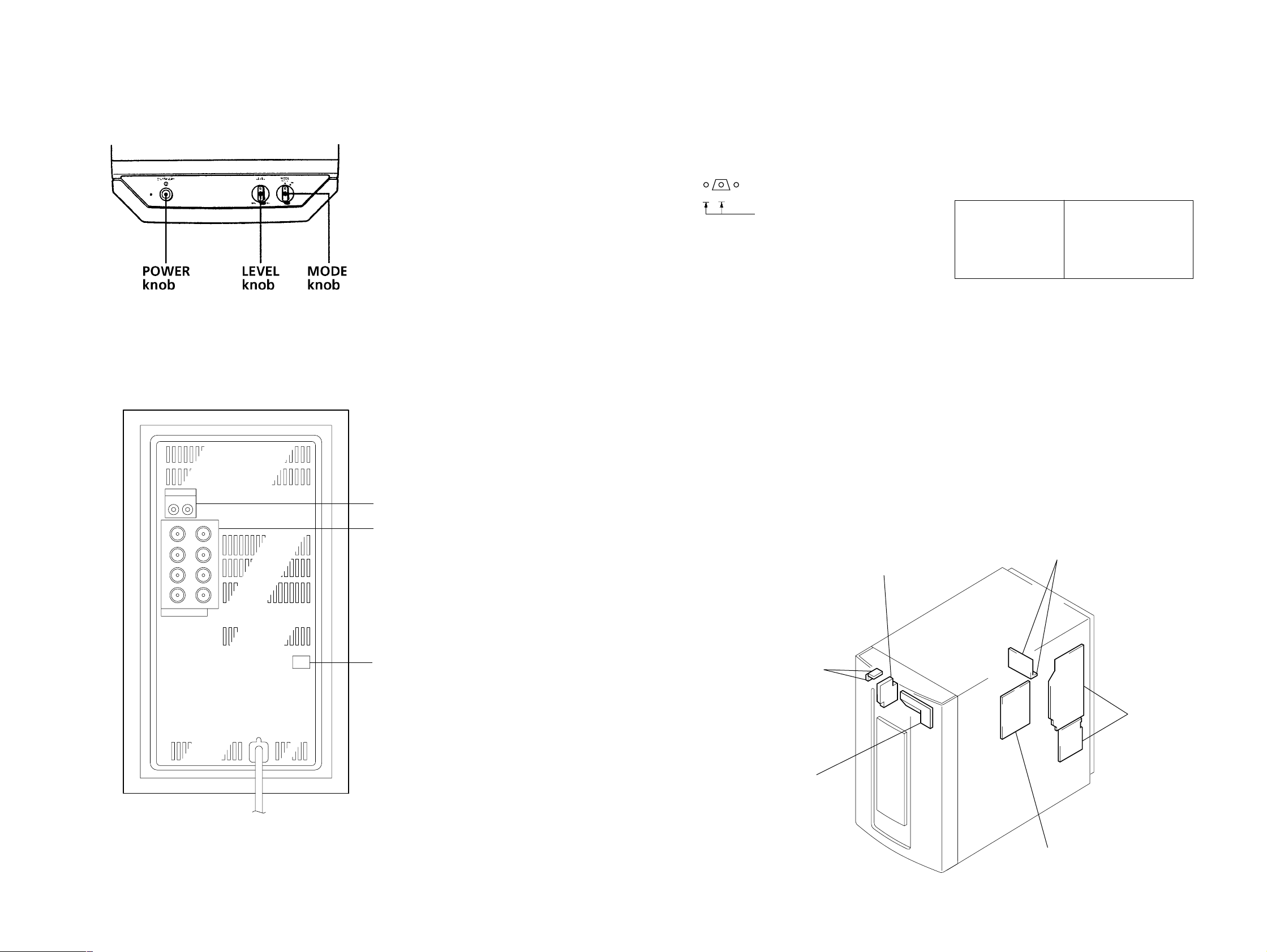
• Location of Controls
SA-WMS7
– Front view –
– Rear view –
2-1. NOTE FOR PRINTED WIRING BOARDS AND SCHEMATIC DIAGRAMS
Note on Printed Wiring Board:
• X : parts extracted from the component side.
• b : Pattern from the side which enables seeing.
(The other layers' patterns are not indicated.)
• Indication of transistor.
Note on Schematic Diagram:
• All capacitors are in µF unless otherwise noted. pF: µµF
50 WV or less are not indicated except for electrolytics
and tantalums.
• All resistors are in Ω and 1/
specified.
• 2 : nonflammable resistor.
• C : panel designation.
Note:
The components identified by mark ! or dotted
line with mark ! are critical for safety.
Replace only with part
number specified.
• U : B+ Line.
• V : B– Line.
• Voltages are dc with respect to ground under no-signal
conditions.
no mark : AUDIO
• Voltages are taken with a VOM (input impedance 10 MΩ).
Voltage variations may be noted due to normal production tolerances.
• Signal path.
F : AUDIO
• Abbreviation
CND : Canadian model
G : German model
MY : Malaysia model
SP : Singapore model
4
W or less unless otherwise
Note:
Les composants identifiés par
une marque ! sont critiques
pour la sécurité.
Ne les remplacer que par une
piéce portant le numéro
spécifié.
• Circuit Boards Location
SA-WMS815
LINE IN/OUT jack
SPEAKER IN/OU
terminal
POWER board
POWER SWITCH board
POWER SAVE
switch
LED board
MAIN boar
CONTROL board
AUTO POWER board
33
SA-VE812ED/VE815ED/WMS815/SS-MS815
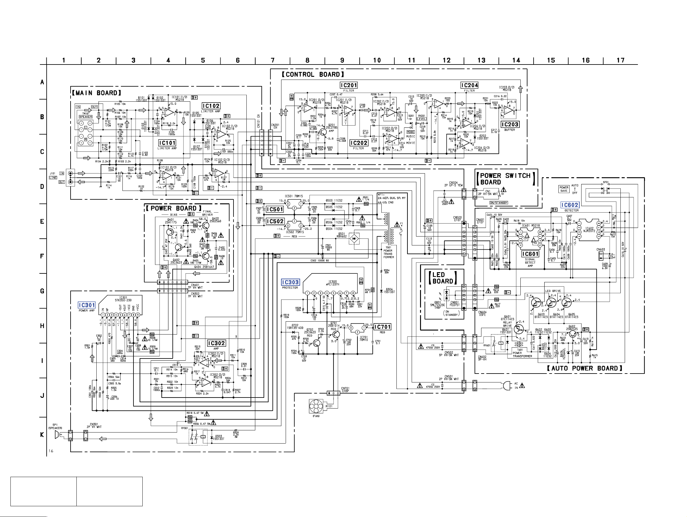
2-2. SCHEMATIC DIAGRAM • See page 7 for IC Block Diagrams.
The components identified by
mark 0 or dotted line with mark
0 are critical for safety.
Replace only with part number
specified.
Les composants identifiés par
une marque 0 sont critiques
pour la sécurité.
Ne les remplacer que par une
pièce portant le numéro spécifié.
44
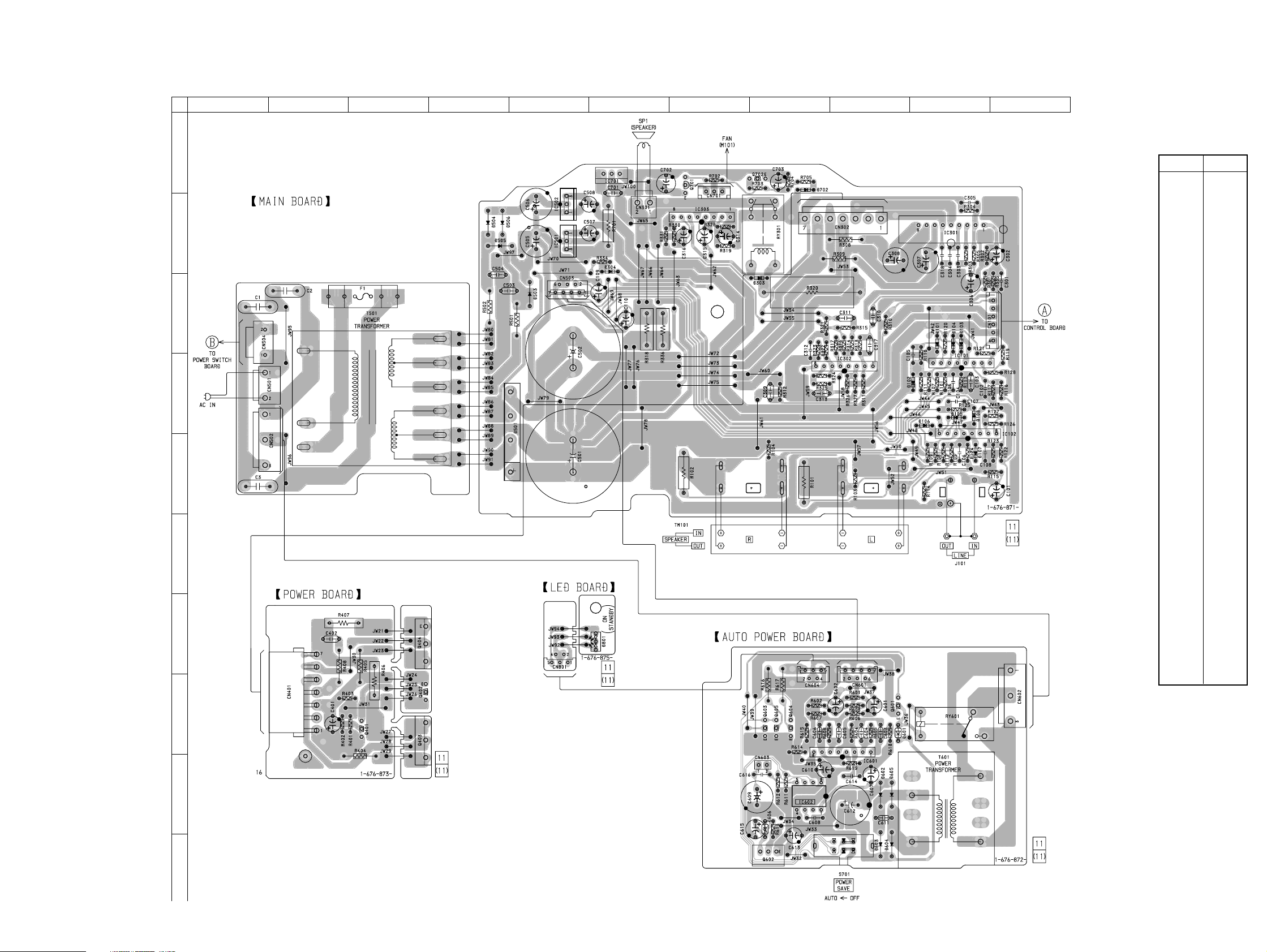
2-3. PRINTED WIRING BOARD MAIN SECTION • See page 3 for Circuit Boards Location.
SA-VE812ED/VE815ED/WMS815/SS-MS815
A
B
C
D
12
34567891011
• Semiconductor
Location
Ref. No. Location
D101 C-10
D102 D-10
D103 C-10
D104 C-10
D105 D-10
D106 D-10
D107 E-10
D108 D-10
D303 B-8
D304 C-6
D501 E-5
D503 C-5
D504 B-4
D505 B-4
D506 B-4
D601 H-9
D602 I-9
D603 J-9
D604 J-9
D605 I-9
D606 I-8
D702 A-8
D801 G-6
E
F
G
H
IC101 C-10
IC102 D-11
IC301 B-10
IC302 D-9
IC303 B-7
IC501 B-5
IC502 B-5
IC601 I-9
IC602 I-8
IC701 A-6
Q401 H-3
Q402 H-4
Q403 H-4
Q404 G-4
Q601 H-9
Q602 J-8
Q603 H-8
Q604 H-8
Q605 H-8
Q701 A-7
Q702 A-8
I
J
55
 Loading...