

Page 1
SA-VE502/VE505/
WMS5/SS-MS5
SERVICE MANUAL
Ver 1.1 2002.09
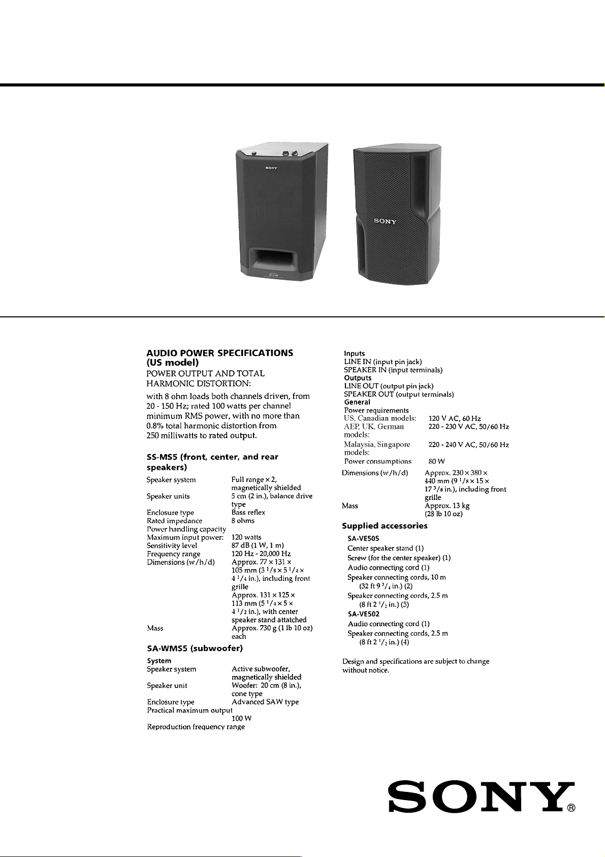
The SA-VE502 system consists of one unit
of SA-WMS5 and two units of SS-MS5.
The SA-VE505 system consists of one unit
of SA-WMS5 and five units of SS-MS5.
Photo: SA-WMS5 Photo: SS-MS5
SPECIFICATIONS
US Model
Canadian Model
AEP Model
UK Model
E Model
9-928-869-12 Sony Corporation
2002I0500-1 Home Audio Company
C 2002.09 Published by Sony Engineering Corporation
MICRO SATELLITE SYSTEM
Page 2
SAFETY CHECK-OUT
After correcting the original service problem, perform the following safety check before releasing the set to the customer:
Check the antenna terminals, metal trim, “metallized” knobs,
screws, and all other exposed metal parts for AC leakage.
Check leakage as described below.
LEAKAGE TEST
The AC leakage from any exposed metal part to earth ground and
from all exposed metal parts to any exposed metal part having a
return to chassis, must not exceed 0.5 mA (500 microampers.).
Leakage current can be measured by any one of three methods.
1. A commercial leakage tester, such as the Simpson 229 or RCA
WT -540A. Follo w the manufacturers’ instructions to use these
instruments.
2. A battery-operated AC milliammeter. The Data Precision 245
digital multimeter is suitable for this job.
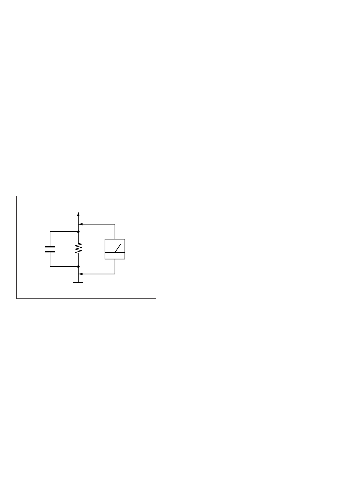
3. Measuring the voltage drop across a resistor by means of a
VOM or battery-operated AC voltmeter. The “limit” indication is 0.75 V, so analog meters must have an accurate lowvoltage scale. The Simpson 250 and Sanwa SH-63Trd are examples of a passive VOM that is suitable. Nearly all battery
operated digital multimeters that have a 2 V A C range are suitable. (See Fig. A)
To Exposed Metal
Parts on Set
AC
1.5 k
0.15 µF
Fig. A. Using an AC voltmeter to check AC leakage.
Ω
Earth Ground
voltmeter
(0.75 V)
SAFETY-RELATED COMPONENT WARNING!!
COMPONENTS IDENTIFIED BY MARK ! OR DOTTED
LINE WITH MARK ! ON THE SCHEMATIC DIAGRAMS
AND IN THE PARTS LIST ARE CRITICAL TO SAFE
OPERATION. REPLACE THESE COMPONENTS WITH
SONY PARTS WHOSE PART NUMBERS APPEAR AS
SHOWN IN THIS MANUAL OR IN SUPPLEMENTS PUBLISHED BY SONY.
ATTENTION AU COMPOSANT AYANT RAPPORT
À LA SÉCURITÉ!
LES COMPOSANTS IDENTIFIÉS P AR UNE MARQUE !
SUR LES DIAGRAMMES SCHÉMATIQUES ET LA LISTE
DES PIÈCES SONT CRITIQUES POUR LA SÉCURITÉ
DE FONCTIONNEMENT. NE REMPLACER CES COMPOSANTS QUE PAR DES PIÈCES SONY DONT LES
NUMÉROS SONT DONNÉS DANS CE MANUEL OU
DANS LES SUPPLÉMENTS PUBLIÉS PAR SONY.
– 2 –
Page 3
SECTION 1
B
These are omitted.
CE
Q
d
T
GENERAL
SECTION 2
DIAGRAMS
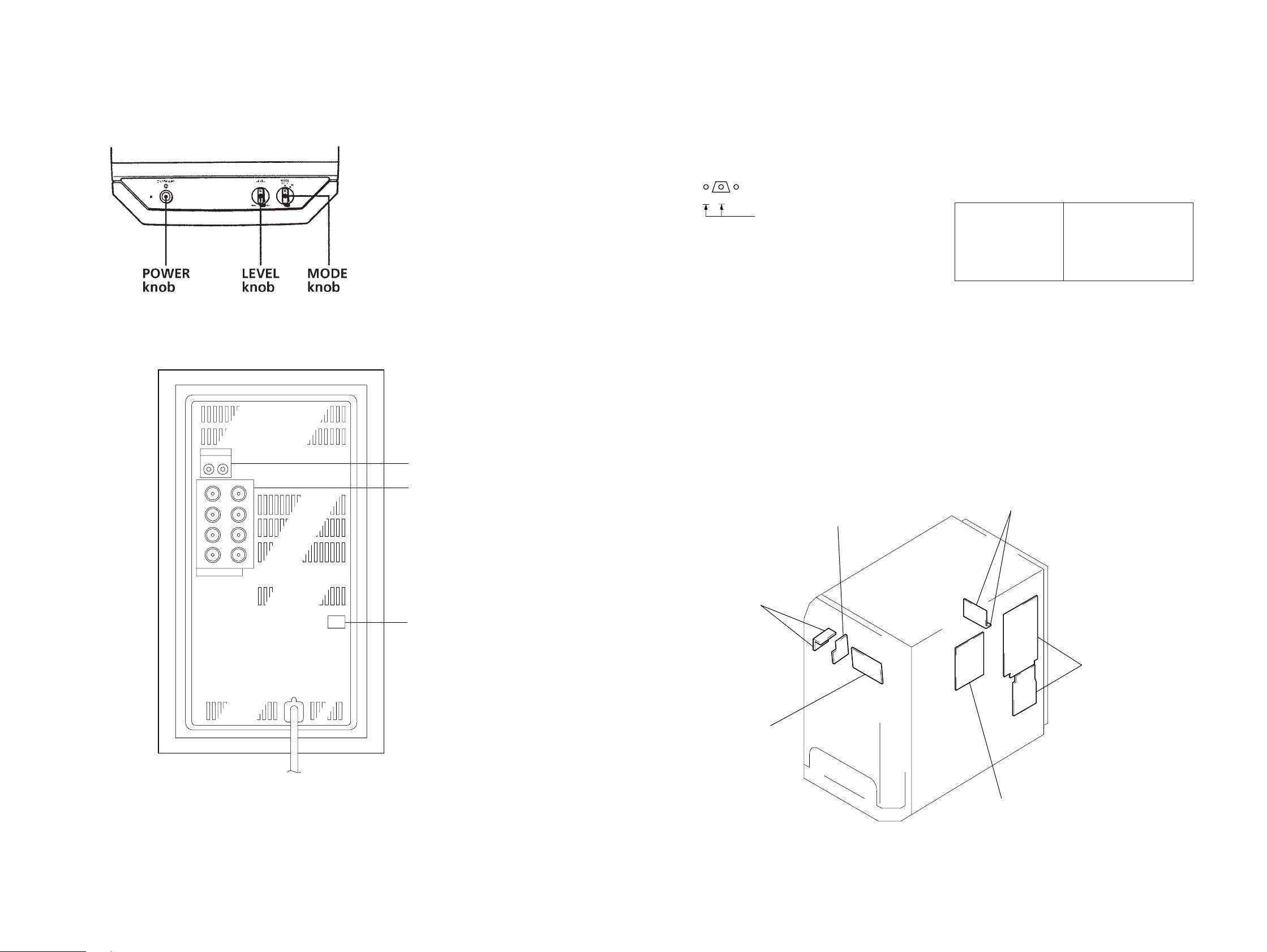
• Location of Controls
SA-WMS5
– Front view –
– Rear view –
2-1. NOTE FOR PRINTED WIRING BOARDS AND SCHEMATIC DIAGRAMS
Note on Printed Wiring Board:
• X : parts extracted from the component side.
• b : Pattern from the side which enables seeing.
(The other layers' patterns are not indicated.)
• Indication of transistor.
Note on Schematic Diagram:
• All capacitors are in µF unless otherwise noted. pF: µµF
50 WV or less are not indicated except for electrolytics
and tantalums.
• All resistors are in Ω and 1/
specified.
• 2 : nonflammable resistor.
• C : panel designation.
Note:
The components identified by mark ! or dotted
line with mark ! are critical for safety.
Replace only with part
number specified.
• U : B+ Line.
• V : B– Line.
• Voltages are dc with respect to ground under no-signal
conditions.
no mark : AUDIO
• Voltages are taken with a V OM (input impedance 10 MΩ).
Voltage variations may be noted due to normal production tolerances.
• Signal path.
F : AUDIO
• Abbreviation
CND : Canadian
4
W or less unless otherwise
Note:
Les composants identifiés par
une marque ! sont critiques
pour la sécurité.
Ne les remplacer que par une
piéce portant le numéro
spécifié.
LINE IN/OUT jack
• Circuit Boards Location
SPEAKER IN/OU
terminal
POWER SAVE
switch
– SA-WMS5 –
POWER board
POWER SWITCH board
LED board
MAIN boar
CONTROL board
AUTO POWER board
– 3 – – 4 –
Page 4
SA-VE502/VE505/WMS5/SS-MS5
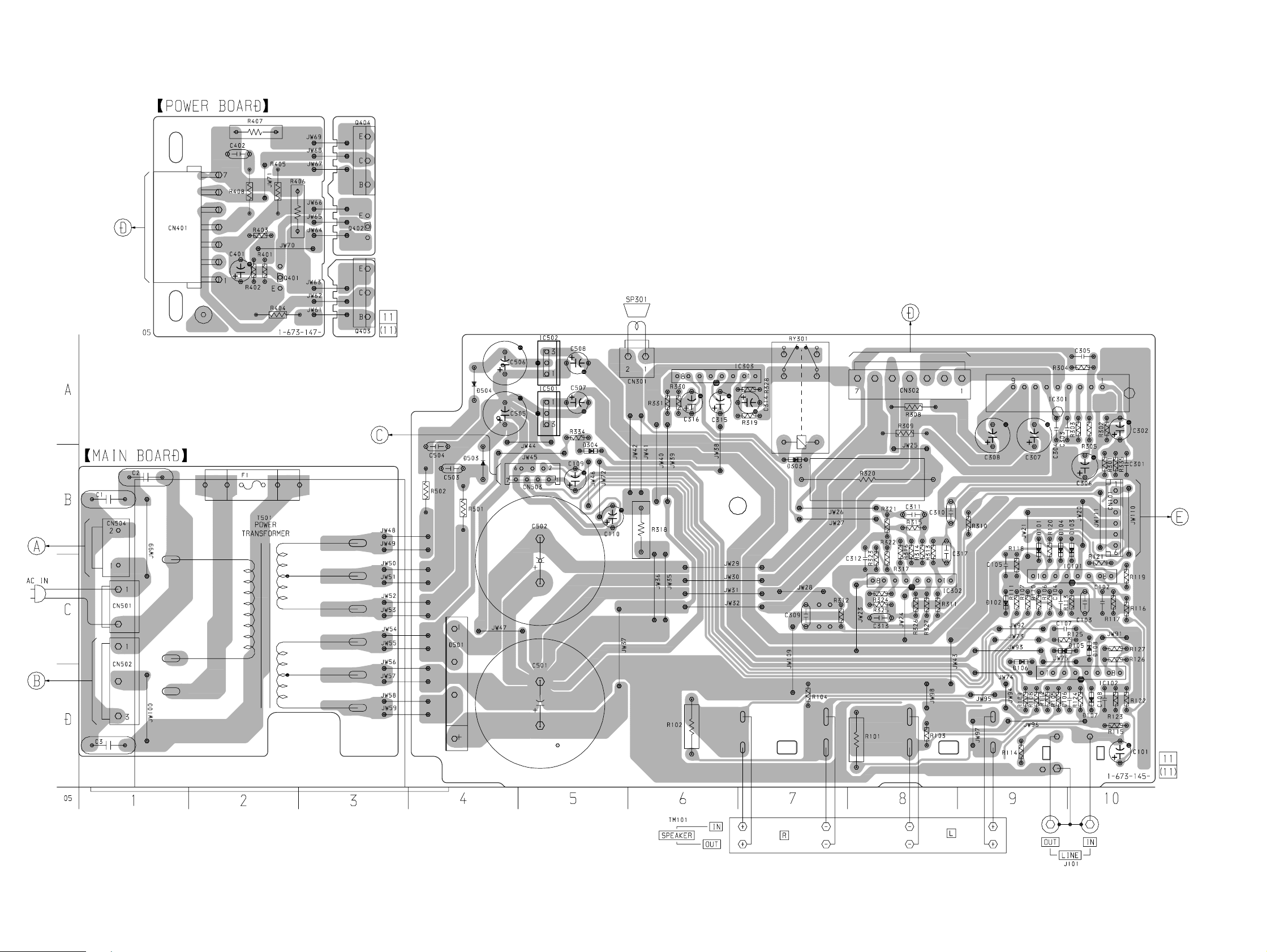
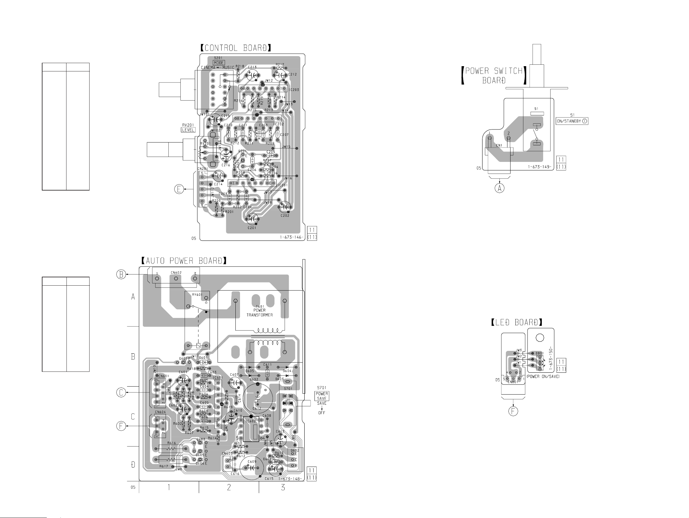
2-2. PRINTED WIRING BOARDS • See page 4 for Circuit Boards Location.
(Page 6)
(Page 5)
(Page 8)
(Page 7)
(Page 7)
(Page 7)
– 5 –
– 6 –
Page 5
• Semiconductor
Location
– MAIN Board –
Ref. No. Location
D101 B-9
D102 C-9
D103 B-10
D104 B-9
D105 C-9
D106 C-9
D107 D-10
D108 C-10
D303 B-7
D304 B-5
D501 D-4
D503 B-4
D504 A-4
IC101 C-10
IC102 D-10
IC301 A-9
IC302 C-8
IC303 A-6
IC501 A-5
IC502 A-5
(Page 6)
SA-VE502/VE505/WMS5/SS-MS5
(Page 5)
• Semiconductor
Location
– AUTO POWER Board –
Ref. No. Location
D601 B-2
D602 B-2
D603 B-3
D604 B-3
D605 B-2
D606 D-3
IC601 C-2
IC602 C-2
Q601 B-1
Q602 D-3
Q603 C-2
Q604 D-2
Q605 D-2
(Page 5)
(Page 5)
(Page 7)
(Page 8)
– 7 –
– 8 –
Page 6

SA-VE502/VE505/WMS5/SS-MS5
2-3. SCHEMATIC DIAGRAM • See page 11 for IC Block Diagrams.
– 9 –
The components identified by mark ! or dotted
line with mark ! are critical for safety.
Replace only with part number specified.
– 10 –
Les composants identifiés par une marque ! sont
critiques pour la sécurité. Ne les remplacer que
par une piéce portant le numéro spécifié.
Page 7

• IC Block Diagrams
– MAIN Board –
IC301 STK350-230
IC303 µPC1237HA
TR1
INPUT
-VEOUT
+VEOUT
V
GND
V
1
NF
2
3
4
5
6
7
SS
8
SUB
CC
9
D1 D2
TR2
R4
TR5
R5
R9
TR8
– AUTO POWER Board –
IC602 NJM2072D
TR3 R1
TR4
TR7
R3
R8
OVER LOAD DET
CC
ON
V
F/F
GND
MUTE
RELAY DRIVE
VCC ON MUTE
VCC
R2
R6
TR6
D4 D3
R7
OFFSET DET
LATCH/
AUTORESET
1 2 3
OFFSET DET
OVER LOAD DET
AUTO RESET
AC OFF
DET
4 5 6 7 8
AC OFF DET
INPUT
GAIN CONT
AMP OUT
GND
1
2
3
4 5
VCC
8
OUTPUT2
7
OUTPUT1
6
RECOVERY
TIME CAP
– 11 –
Page 8

SECTION 3
EXPLODED VIEWS
NOTE:
• -XX and -X mean standardized parts, so they
may have some difference from the original
one.
• Color Indication of Appearance Parts
Example:
KNOB, BALANCE (WHITE) . . . (RED)
• Abbreviation
CND: Canadian model
G : German model
↑↑
Parts Color Cabinet's Color
MY : Malaysia model
SP : Singapore model
(1) FRONT PANEL SECTION
(SA-WMS5)
10
9
2
1
#9
• Items marked “*” are not stocked since they
are seldom required for routine service. Some
delay should be anticipated when ordering
these items.
• The mechanical parts with no reference number in the exploded views are not supplied.
• Hardware (# mark) list and accessories are
given in the last of the electrical parts list.
supplied with
RV201, S201
3
11
#1
#2
#3
not supplied
4
The components identified by
mark ! or dotted line with mark
! are critical for safety.
Replace only with part number
specified.
Les composants identifiés par une
marque ! sont critiquens pour la
sécurité.
Ne les remplacer que par une pièce
portant le numéro spécifié.
#10
#8
SP1
#8
#9
5
A
#10
not supplied
7
A
8
6
Ref. No. Part No. Description Remark
1 X-4951-099-1 FRAME ASSY, GRILLE
2 X-4951-100-1 PANEL ASSY, FRONT
3 1-673-150-11 LED BOARD
4 1-673-149-11 POWER SWITCH BOARD
5 1-673-146-11 CONTROL BOARD
6 4-217-284-01 PACKING
Ref. No. Part No. Description Remark
7 A-4411-447-A CABINET ASSY, SPEAKER
8 4-981-864-01 FOOT
9 4-217-642-01 SHEET
10 4-999-482-21 KNOB (VOL)
11 4-973-938-41 KNOB (A), PUSH
SP1 1-529-296-11 SPEAKER (20cm)
– 12 –
Page 9

(2) AMPLIFIER SECTION
56
US, CND AEP, UK, G,
SP, MY
SP UK
54
55
56
57
58
T501
B
B
#6
#4
#4
#4
#4
#4
#4
#6
#6
#5
#5
T601
53
59
52
51
60
not
supplied
not supplied
not supplied
not
supplied
(SA-WMS5)
Ver 1.1
The components identified by
mark ! or dotted line with
mark ! are critical for safety .
Replace only with part number specified.
Les composants identifiés par une
marque ! sont critiques pour la
sécurité.
Ne les remplacer que par une pièce
portant le numéro spécifié.
Ref. No. Part No. Description Remark
51 1-673-147-11 POWER BOARD
52 A-4419-290-A AUTO POWER BOARD, COMPLETE
53 4-217-294-01 PANEL, REAR
54 A-4419-286-A MAIN BOARD, COMPLETE
* 55 3-703-244-00 BUSHING (2104), CORD
! 56 1-769-744-11 CORD, POWER (AEP, UK, G, MY, SP)
! 56 1-783-531-11 CORD, POWER (US, CND)
! 57 1-569-008-21 ADAPTOR, CONVERSION 2P (SP)
Ref. No. Part No. Description Remark
! 58 1-770-019-21 ADAPTOR, CONVERSION PLUG 3P (UK)
59 3-710-901-11 SCREW, TAPPING
60 1-824-346-11 WIRE, FLAT TYPE 5P
! T501 1-433-726-11 TRANSFORMER, POWER (US, CND)
! T501 1-433-728-11 TRANSFORMER, POWER (EXCEPT US, CND)
! T601 1-433-731-11 TRANSFORMER, POWER (US, CND)
! T601 1-433-732-11 TRANSFORMER, POWER (EXCEPT US, CND)
– 13 –
Page 10

(3) SS-MS5
not supplied
105
104
SP100
103
108
102
101
#7
103
SP100
not supplied
107
106
109
Ref. No. Part No. Description Remark
101 X-4951-148-1 GRILLE ASSY, FRONT
102 X-4951-498-1 EMBLEM ASSY, SONY
103 4-217-715-01 SCREW (3.5X50), +P TAPPING
104 4-217-295-01 PANEL, FRONT
105 1-694-516-11 TERMINAL, SPEAKER
Ref. No. Part No. Description Remark
106 X-4951-147-1 CABINET ASSY
107 4-986-971-11 SCREW (3.5)
108 3-701-436-21 WASHER, POLYEHTHYLENE
109 4-220-713-01 SHEET
SP100 1-529-292-11 SPEAKER (5cm)
– 14 –
Page 11

SECTION 4
ELECTRICAL PARTS LIST
AUTO POWER
CONTROL
NOTE:
• Due to standardization, replacements in the
parts list may be different from the parts specified in the diagrams or the components used
on the set.
• -XX and -X mean standardized parts, so they
may have some difference from the original
one.
• RESISTORS
All resistors are in ohms.
METAL: Metal-film resistor.
METAL OXIDE: Metal oxide-film resistor.
F: nonflammable
• Abbreviation
CND: Canadian model SP : Singapore model
Ref. No. Part No. Description Remark Ref. No. Part No. Description Remark
A-4419-290-A AUTO POWER BOARD, COMPLETE
****************************
< CAPACITOR >
C601 1-126-964-11 ELECT 10uF 20% 50V
C602 1-126-964-11 ELECT 10uF 20% 50V
C603 1-162-306-11 CERAMIC 0.01uF 20% 16V
C604 1-162-306-11 CERAMIC 0.01uF 20% 16V
C605 1-164-159-11 CERAMIC 0.1uF 50V
• Items marked “*” are not stocked since they
are seldom required for routine service.
Some delay should be anticipated when ordering these items.
• SEMICONDUCTORS
In each case, u: µ, for example:
uA. . : µA. . uPA. . : µPA. .
uPB. . : µPB. . uPC. . : µPC. .
uPD. . : µPD. .
• CAPACITORS
uF: µF
• COILS
uH: µH
Q604 8-729-422-57 TRANSISTOR UN4111
Q605 8-729-422-57 TRANSISTOR UN4111
R601 1-247-887-00 CARBON 220K 5% 1/4W
R602 1-247-887-00 CARBON 220K 5% 1/4W
R603 1-249-431-11 CARBON 15K 5% 1/4W
R604 1-249-433-11 CARBON 22K 5% 1/4W
R605 1-249-435-11 CARBON 33K 5% 1/4W
The components identified by
mark ! or dotted line with mark
! are critical for safety.
Replace only with part number
specified.
Les composants identifiés par une
marque ! sont critiquens pour la
sécurité.
Ne les remplacer que par une pièce
portant le numéro spécifié.
When indicating parts by reference
number, please include the board.
< RESISTOR >
C606 1-164-159-11 CERAMIC 0.1uF 50V
C607 1-126-956-91 ELECT 0.1uF 20% 50V
C608 1-162-294-31 CERAMIC 0.001uF 10% 50V
C609 1-126-916-11 ELECT 1000uF 20% 6.3V
C610 1-126-964-11 ELECT 10uF 20% 50V
C611 1-161-494-00 CERAMIC 0.022uF 25V
C612 1-126-942-61 ELECT 1000uF 20% 25V
C613 1-126-964-11 ELECT 10uF 20% 50V
C614 1-162-294-31 CERAMIC 0.001uF 10% 50V
C615 1-104-665-11 ELECT 100uF 20% 25V
C616 1-162-294-31 CERAMIC 0.001uF 10% 50V
< CONNECTOR >
CN601 1-568-439-11 SOCKET, CONNECTOR 7P
* CN602 1-564-687-11 PIN, CONNECTOR 3P
* CN603 1-565-513-11 PIN, CONNECTOR 2P
CN604 1-569-315-11 SOCKET, CONNECTOR 5P
< DIODE >
D601 8-719-991-33 DIODE 1SS133T-77
D602 8-719-200-82 DIODE 11ES2
D603 8-719-200-82 DIODE 11ES2
D604 8-719-200-82 DIODE 11ES2
D605 8-719-200-82 DIODE 11ES2
R606 1-249-431-11 CARBON 15K 5% 1/4W
R607 1-249-433-11 CARBON 22K 5% 1/4W
R608 1-249-435-11 CARBON 33K 5% 1/4W
R611 1-249-431-11 CARBON 15K 5% 1/4W
R612 1-249-431-11 CARBON 15K 5% 1/4W
R613 1-249-415-11 CARBON 680 5% 1/4W
R614 1-249-417-11 CARBON 1K 5% 1/4W
R615 1-249-417-11 CARBON 1K 5% 1/4W
! R616 1-215-865-81 METAL OXIDE 220 5% 1W F
! R617 1-215-865-81 METAL OXIDE 220 5% 1W F
R618 1-249-429-11 CARBON 10K 5% 1/4W
R619 1-249-429-11 CARBON 10K 5% 1/4W
< RELAY >
! RY601 1-755-276-11 RELAY, POWER
< SWITCH >
S701 1-570-707-31 SWITCH, SLIDE (POWER SAVE)
< TRANSFORMER >
! T601 1-433-731-11 TRANFOORMER, POWER (US, CND)
! T601 1-433-732-11 TRANFOORMER, POWER (EXCEPT US, CND)
************************************************************
D606 8-719-985-85 DIODE HZS6A2L
< IC >
IC601 8-759-634-50 IC M5218AL
IC602 8-759-701-55 IC NJM2072D
< TRANSISTOR >
Q601 8-729-029-66 TRANSISTOR DTC114ESA
Q602 8-729-026-68 TRANSISTOR 2SD2525
Q603 8-729-422-57 TRANSISTOR UN4111
1-673-146-11 CONTROL BOARD
**************
< CAPACITOR >
C201 1-104-664-11 ELECT 47uF 20% 25V
C202 1-104-664-11 ELECT 47uF 20% 25V
C203 1-136-176-00 FILM 0.82uF 5% 50V
C204 1-136-158-00 FILM 0.027uF 5% 50V
C205 1-136-163-00 FILM 0.068uF 5% 50V
C206 1-136-163-00 FILM 0.068uF 5% 50V
– 15 –
Page 12

CONTROL LED MAIN
Ref. No. Part No. Description Remark
C207 1-136-170-00 FILM 0.27uF 5% 50V
C208 1-136-170-00 FILM 0.27uF 5% 50V
C210 1-136-177-00 FILM 1uF 5% 50V
C211 1-136-165-00 FILM 0.1uF 5% 50V
C212 1-126-965-11 ELECT 22uF 20% 50V
C213 1-126-965-11 ELECT 22uF 20% 50V
C214 1-126-965-11 ELECT 22uF 20% 50V
C215 1-126-964-11 ELECT 10uF 20% 50V
C216 1-126-963-11 ELECT 4.7uF 20% 50V
< CONNECTOR >
* CN201 1-564-520-11 PLUG, CONNECTOR 5P
< IC >
IC201 8-759-634-50 IC M5218AL
IC202 8-759-634-50 IC M5218AL
IC203 8-759-634-50 IC M5218AL
< TRANSISTOR >
Q201 8-729-178-55 TRANSISTOR 2SC2785-E
< RESISTOR >
R201 1-249-427-11 CARBON 6.8K 5% 1/4W
R202 1-249-427-11 CARBON 6.8K 5% 1/4W
R203 1-247-887-00 CARBON 220K 5% 1/4W
R204 1-249-435-11 CARBON 33K 5% 1/4W
R205 1-249-417-11 CARBON 1K 5% 1/4W
R206 1-249-417-11 CARBON 1K 5% 1/4W
R207 1-247-883-00 CARBON 150K 5% 1/4W
R208 1-249-435-11 CARBON 33K 5% 1/4W
R209 1-249-427-11 CARBON 6.8K 5% 1/4W
R210 1-249-437-11 CARBON 47K 5% 1/4W
R211 1-249-432-11 CARBON 18K 5% 1/4W
R212 1-249-432-11 CARBON 18K 5% 1/4W
R213 1-249-417-11 CARBON 1K 5% 1/4W
R214 1-249-431-11 CARBON 15 5% 1/4W
R215 1-249-417-11 CARBON 1K 5% 1/4W
R216 1-249-427-11 CARBON 6.8K 5% 1/4W
R217 1-247-887-00 CARBON 220K 5% 1/4W
R218 1-247-887-00 CARBON 220K 5% 1/4W
R219 1-249-429-11 CARBON 10K 5% 1/4W
Ref. No. Part No. Description Remark
A-4419-286-A MAIN BOARD, COMPLETE
*********************
1-533-233-11 HOLDER, FUSE
< CAPACITOR >
! C1 1-113-924-11 CERAMIC 0.0047uF 20% 250V
! C2 1-113-924-11 CERAMIC 0.0047uF 20% 250V
! C3 1-113-924-11 CERAMIC 0.0047uF 20% 250V
C101 1-126-964-11 ELECT 10uF 20% 50V
C102 1-162-282-31 CERAMIC 100PF 10% 50V
C103 1-136-176-00 FILM 0.82uF 5% 50V
C104 1-162-282-31 CERAMIC 100PF 10% 50V
C105 1-162-294-31 CERAMIC 0.001uF 10% 50V
C106 1-162-292-31 CERAMIC 680PF 10% 50V
C107 1-162-288-31 CERAMIC 330PF 10% 50V
C108 1-162-282-31 CERAMIC 100PF 10% 50V
C109 1-126-964-11 ELECT 10uF 20% 50V
C110 1-126-964-11 ELECT 10uF 20% 50V
C301 1-162-282-31 CERAMIC 100PF 10% 50V
C302 1-126-963-11 ELECT 4.7uF 20% 50V
C303 1-162-219-31 CERAMIC 68PF 5% 50V
C304 1-162-289-31 CERAMIC 390PF 10% 50V
C305 1-162-194-31 CERAMIC 3.9PF 10% 50V
C306 1-126-934-11 ELECT 220uF 20% 10V
C307 1-128-560-11 ELECT 22uF 20% 100V
C308 1-128-560-11 ELECT 22uF 20% 100V
C309 1-130-483-00 MYLAR 0.01uF 5% 50V
C310 1-136-177-00 FILM 1uF 5% 50V
C311 1-130-495-00 MYLAR 0.1uF 5% 50V
C312 1-162-294-31 CERAMIC 0.001uF 10% 50V
C313 1-130-491-00 MYLAR 0.047uF 5% 50V
C314 1-104-665-11 ELECT 100uF 20% 10V
C315 1-126-963-11 ELECT 4.7uF 20% 50V
C316 1-104-664-11 ELECT 47uF 20% 25V
C317 1-162-209-31 CERAMIC 27PF 5% 50V
C501 1-127-891-11 ELECT 12000uF 20% 63V
C502 1-127-891-11 ELECT 12000uF 20% 63V
C503 1-136-165-00 FILM 0.1uF 5% 50V
C504 1-136-165-00 FILM 0.1uF 5% 50V
C505 1-126-941-11 ELECT 470uF 20% 25V
< VARIABLE RESISTOR >
RV201 1-225-826-11 RES, VAR, CARBON 20K (LEVEL)
< SWITCH >
S201 1-771-632-11 SWITCH, ROTARY (MODE)
************************************************************
1-673-150-11 LED BOARD
**********
< CONNECTOR >
CN801 1-569-299-11 SOCKET, CONNECTOR (L TYRE) 5P
< LED >
D801 8-719-061-31 LED SML72420CTH8F (POWER ON/SAVE)
************************************************************
– 16 –
C506 1-126-941-11 ELECT 470uF 20% 25V
C507 1-104-664-11 ELECT 47uF 20% 25V
C508 1-104-664-11 ELECT 47uF 20% 25V
< CONNECTOR >
* CN101 1-564-521-11 PLUG, CONNECTOR 6P
* CN301 1-565-792-11 PIN, CONNECTOR 2P
* CN302 1-564-915-11 PIN, CONNECTOR 7P
CN501 1-564-321-00 PIN, CONNECTOR 2P
* CN502 1-564-687-11 PIN, CONNECTOR 3P
CN503 1-568-439-11 SOCKET, CONNECTOR 7P
* CN504 1-580-230-11 PIN, CONNECTOR (PC BOARD) 2P
< DIODE >
D101 8-719-991-33 DIODE 1SS133T-77
D102 8-719-991-33 DIODE 1SS133T-77
The components identified by
mark ! or dotted line with
mark ! are critical for safety.
Replace only with part number specified.
Les composants identifiés par une
marque ! sont critiques pour la
sécurité.
Ne les remplacer que par une pièce
portant le numéro spécifié.
Page 13

MAIN PO WER
Ref. No. Part No. Description Remark
D103 8-719-991-33 DIODE 1SS133T-77
D104 8-719-991-33 DIODE 1SS133T-77
D105 8-719-991-33 DIODE 1SS133T-77
D106 8-719-991-33 DIODE 1SS133T-77
D107 8-719-991-33 DIODE 1SS133T-77
D108 8-719-991-33 DIODE 1SS133T-77
D303 8-719-991-33 DIODE 1SS133T-77
D304 8-719-991-33 DIODE 1SS133T-77
D501 8-719-302-37 DIODE RBV-602
D503 8-719-200-82 DIODE 11ES2
D504 8-719-200-82 DIODE 11ES2
< FUSE >
! F1 1-532-501-31 FUSE (T0.8AL/250V) (EXCEPT US, CND)
! F1 1-533-296-11 FUSE, GLASS CYLINDRICAL (DIA.5) (2A/125V)
(US, CND)
< IC >
IC101 8-759-634-50 IC M5218AL
IC102 8-759-634-50 IC M5218AL
IC301 8-749-011-16 IC STK350-230
IC302 8-759-634-50 IC M5218AL
IC303 8-759-111-68 IC uPC1237HA
Ref. No. Part No. Description Remark
R301 1-249-433-11 CARBON 22K 5% 1/4W
R302 1-249-438-11 CARBON 56K 5% 1/4W
R303 1-249-413-11 CARBON 470 5% 1/4W
R304 1-249-438-11 CARBON 56K 5% 1/4W
R305 1-249-442-11 CARBON 510 5% 1/4W
! R308 1-247-688-11 CARBON 10 5% 1/4W F
! R309 1-247-688-11 CARBON 10 5% 1/4W F
R310 1-249-417-11 CARBON 1K 5% 1/4W
R311 1-249-429-11 CARBON 10K 5% 1/4W
R312 1-249-437-11 CARBON 47K 5% 1/4W
R313 1-247-885-11 CARBON 180K 5% 1/4W
R314 1-249-429-11 CARBON 10K 5% 1/4W
R315 1-249-431-11 CARBON 15K 5% 1/4W
R316 1-249-415-11 CARBON 680 5% 1/4W
R317 1-249-417-11 CARBON 1K 5% 1/4W
! R318 1-217-158-00 METAL 0.47 10% 5W F
R319 1-249-441-11 CARBON 100K 5% 1/4W
! R320 1-216-505-51 METAL OXIDE 1.2K 5% 5W F
R321 1-247-838-00 CARBON 2K 5% 1/4W
R322 1-249-429-11 CARBON 10K 5% 1/4W
R323 1-249-420-11 CARBON 1.8K 5% 1/4W
R324 1-249-421-11 CARBON 2.2K 5% 1/4W
R325 1-249-425-11 CARBON 4.7K 5% 1/4W
IC501 8-759-604-40 IC M5F78M15
IC502 8-759-604-46 IC M5F79M15
< JACK >
J101 1-785-795-11 JACK, PIN 2P (LINE IN/OUT)
< RESISTOR >
R101 1-260-107-11 CARBON 4.7K 5% 1/2W
R102 1-260-107-11 CARBON 4.7K 5% 1/2W
R103 1-249-421-11 CARBON 2.2K 5% 1/4W
R104 1-249-421-11 CARBON 2.2K 5% 1/4W
R105 1-249-429-11 CARBON 10K 5% 1/4W
R106 1-249-429-11 CARBON 10K 5% 1/4W
R107 1-249-429-11 CARBON 10K 5% 1/4W
R108 1-249-429-11 CARBON 10K 5% 1/4W
R109 1-249-429-11 CARBON 10K 5% 1/4W
R110 1-249-429-11 CARBON 10K 5% 1/4W
R111 1-249-429-11 CARBON 10K 5% 1/4W
R112 1-249-429-11 CARBON 10K 5% 1/4W
R113 1-249-417-11 CARBON 1K 5% 1/4W
R114 1-249-417-11 CARBON 1K 5% 1/4W
R115 1-247-887-00 CARBON 220K 5% 1/4W
R116 1-249-417-11 CARBON 1K 5% 1/4W
R117 1-247-887-00 CARBON 220K 5% 1/4W
R118 1-249-421-11 CARBON 2.2K 5% 1/4W
R119 1-249-427-11 CARBON 6.8K 5% 1/4W
R120 1-249-417-11 CARBON 1K 5% 1/4W
R326 1-247-860-11 CARBON 16K 5% 1/4W
R327 1-249-422-11 CARBON 2.7K 5% 1/4W
R328 1-249-441-11 CARBON 100K 5% 1/4W
R330 1-249-439-11 CARBON 68K 5% 1/4W
R331 1-249-433-11 CARBON 22K 5% 1/4W
R334 1-249-436-11 CARBON 39K 5% 1/4W
R335 1-249-432-11 CARBON 18K 5% 1/4W
! R501 1-249-381-11 CARBON 1 5% 1/4W F
! R502 1-249-381-11 CARBON 1 5% 1/4W F
< RELAY >
RY301 1-515-920-11 RELAY (24V)
< TRANSFORMER >
! T501 1-433-726-11 TRANFOORMER, POWER (US, CND)
! T501 1-433-728-11 TRANFOORMER, POWER (EXCEPT US, CND)
< TERMINAL >
TM101 1-537-737-11 TERMINAL BOARD (SPEAKER IN/OUT)
************************************************************
1-673-147-11 POWER BOARD
*************
< CAPACITOR >
C401 1-104-664-11 ELECT 47uF 20% 25V
C402 1-137-372-11 FILM 0.022uF 5% 50V
R121 1-249-417-11 CARBON 1K 5% 1/4W
R122 1-249-417-11 CARBON 1K 5% 1/4W
R123 1-249-441-11 CARBON 100K 5% 1/4W
R124 1-249-429-11 CARBON 10K 5% 1/4W
R125 1-249-429-11 CARBON 10K 5% 1/4W
R126 1-249-437-11 CARBON 47K 5% 1/4W
R127 1-247-903-00 CARBON 1M 5% 1/4W
< CONNECTOR >
* CN401 1-770-318-11 PIN, CONNECTOR 7P
< TRANSISTOR/IC >
Q401 8-729-119-76 TRANSISTOR 2SA1175-HFE
Q402 8-729-141-30 TRANSISTOR 2SC3623A-LK
The components identified by
mark ! or dotted line with
mark ! are critical for safety.
Replace only with part num-
– 17 –
ber specified.
Les composants identifiés par une
marque ! sont critiques pour la
sécurité.
Ne les remplacer que par une pièce
portant le numéro spécifié.
Page 14

SA-VE502/VE505/WMS5/SS-WMS5
Ver 1.1
POWER POWER SWITCH
Ref. No. Part No. Description Remark
Q403 8-749-010-25 IC MN2488-OPY-M
Q404 8-749-010-26 IC MP1620-OPY-M
< RESISTOR >
R401 1-249-421-11 CARBON 2.2K 5% 1/4W
R402 1-249-437-11 CARBON 47K 5% 1/4W
R403 1-249-414-11 CARBON 560 5% 1/4W
! R404 1-249-408-11 CARBON 180 5% 1/4W F
! R405 1-249-408-11 CARBON 180 5% 1/4W F
! R406 1-217-151-00 METAL 0.22 10% 2W F
! R407 1-217-151-00 METAL 0.22 10% 2W F
! R408 1-249-393-11 CARBON 10 5% 1/4W F
************************************************************
1-673-149-11 POWER SWITCH BOARD
********************
< CONNECTOR >
CN1 1-564-321-00 PIN, CONNECTOR 2P
< SWITCH >
! S1 1-554-920-11 SWITCH, PUSH (AC POWER) (1 KEY)
(ON/STANDBY U)
************************************************************
Ref. No. Part No. Description Remark
ACCESSORIES
************
1-769-329-21 CORD, CONNECTION (PIN-PIN)
1-790-503-11 CORD, SPEAKER (2.5m)
1-790-503-21 CORD, SPEAKER (10m) (VE505)
3-701-443-21 WASHER, 5 DIA.
3-866-761-11 MANUAL, INSTRUCTION (ENGLISH, FRENCH)
3-866-761-21 MANUAL, INSTRUCTION (GERMAN, SPANISH,
DUTCH, SWEDISH, ITALIAN, PORTUGUESE,
POLISH, RUSSIAN, DANISH, FINNISH,
CHINESE) (EXCEPT US, CND)
4-219-450-01 SCREW (M5X16)
X-4951-476-1 STAY ASSY
X-4951-477-1 BASE ASSY
MISCELLANEOUS
**************
! 56 1-769-744-11 CORD, POWER (AEP, UK, G, MY, SP)
! 56 1-783-531-11 CORD, POWER (US, CND)
! 57 1-569-008-21 ADAPTOR, CONVERSION 2P (SP)
! 58 1-770-019-21 ADAPTOR, CONVERSION PLUG 3P (UK)
60 1-824-346-11 WIRE, FLAT TYPE 5P
105 1-694-516-11 TERMINAL, SPEAKER
SP1 1-529-296-11 SPEAKER (20cm)
SP100 1-529-292-11 SPEAKER (5cm)
! T501 1-433-726-11 TRANSFORMER, POWER (US, CND)
! T501 1-433-728-11 TRANSFORMER, POWER (EXCEPT US, CND)
! T601 1-433-731-11 TRANSFORMER, POWER (US, CND)
! T601 1-433-732-11 TRANSFORMER, POWER (EXCEPT US, CND)
************************************************************
**************
HARDWARE LIST
**************
#1 7-685-645-79 SCREW +P 3X6 TYPE2 SLIT
#2 7-685-146-29 SCREW +P 3X8 TYPE2 SLIT
#3 7-682-147-01 SCREW +P 3X6
#4 7-685-648-79 SCREW +P 3X12 TYPE2 NON-SLIT
#5 7-685-660-19 SCREW +BVTP 4X10 TYPE2 N-S
#6 7-685-647-79 SCREW +P 3X10 TYPE2 NON-SLIT
#7 7-624-200-11 NUT, PUSH 2
#8 7-685-163-01 SCREW +P 4X16 TYPE1
#9 7-685-116-01 SCREW +PTP 4X30 TYPE1
#10 7-685-662-79 SCREW +BVTP 4X14 TYPE2 N-S
************************************************************
– 18 –
The components identified by
mark ! or dotted line with
mark ! are critical for safety.
Replace only with part number specified.
Les composants identifiés par une
marque ! sont critiques pour la
sécurité.
Ne les remplacer que par une pièce
portant le neméro spécifié.
Page 15

SERVICE MANUAL
SUPPLEMENT-1
File this supplement with the service manual.
Subject: Change of the Fuse
SA-VE502/VE505/
WMS5/SS-MS5
US Model
Canadian Model
AEP Model
UK Model
E Model
(ENG-00001)
! : Indicates changed portion.
Page Before Change After Change
Location: F – H, 8 – 11
9,
10
Location: F – H, 8 – 11
!
Ref. No. Part No. Description
0 F1 1-532-501-31 FUSE (T0.8AL/250V)
17
(EXCEPT US, Canadian)
Ref. No. Part No. Description
0 F1 1-532-463-11 FUSE (T1AL/250V) (EXCEPT US, Canadian)
$$
The components identified by
mark 0 or dotted line with
mark 0 are critical for safety .
Replace only with part number specified.
Les composants identifiés par une
marque 0 sont critiques pour la
sécurité.
Ne les remplacer que par une pièce
portant le numéro spécifié.
Page 16

SA-VE502/VE505/WMS5/SS-MS5
REVISION HISTORY
Clicking the version allows you to jump to the revised page.
Also, clicking the version at the upper right on the revised page allows you to jump to the next revised
page.
Ver. Date Description of Revision
1.0 1999.04 New
2000.11 Supplement-1
1.1 2002.09 Addition of Ref. No. 60 on EXPLODED VIEWS (SPM-02081)
 Loading...