

Sony SSC-SD26P, SSC-SD36P Operating Instructions Manual

4-155-823-04 (1)
Color Video Camera
Operating Instructions
Before operating the unit, please read this manual thoroughly and retain it for future
reference.
SSC-SD26P/SD36P
© 2009 Sony Corporation

Table of Contents
Outline
Features............................................................3
Safety information.............................................3
Precautions.......................................................4
Typical CCD phenomenon ................................4
Main/Accessory ................................................5
Component Diagram.........................................6
Connections and setup ....................................6
Cold Start..........................................................6
Cold Start procedures.......................................... 6
Other menus .................................................. 18
FREEZE ACTIVITY.........................................18
SCAN TILT ANGLE.........................................18
SCHEDULE ......................................................19
MOTION DETECTION....................................19
SYSTEM ........................................................ 20
WEEK................................................................20
TIME .................................................................20
PASSWORD ......................................................20
POWER UP Mode.............................................20
LOAD FACTORY DEFAULT...........................21
E-FLIP ...............................................................21
MIRROR............................................................21
LANGUAGE .....................................................21
ACTION ............................................................22
RECORDING TOUR ...................................... 22
Operation Instructions
Activate OSD Menu ..........................................7
Horizontal Pan/Vertical Tilt ...............................7
Scan function ...................................................7
Auto Scan............................................................ 7
Frame Scanning................................................... 7
Random Scanning ............................................... 8
Camera Settings ...............................................9
FOCUS................................................................ 9
WHITE BALANCE (WB).................................. 9
AUTO EXPOSURE (AE) ................................. 10
ZOOM LIMIT................................................... 10
ZOOM SPEED.................................................. 11
SHARPNESS .................................................... 11
SYNC LOCK .................................................... 11
PRIVACY ZONE .............................................. 12
ALARM ACTION ............................................ 12
Horizontal Pan/Vertical Tilt Setup ...................13
AUTO FLIP....................................................... 13
Proportional P/T................................................ 13
SCAN LIMIT STOPS ....................................... 14
MANUAL SPEED............................................ 14
MANUAL LIMIT STOPS ................................ 14
RECOVER TIME ............................................. 15
SCAN SPEED................................................... 15
STOP TIME ...................................................... 15
MAX SPEED .................................................... 15
TOUR................................................................ 15
CAMERA TITLE..............................................16
CAMERA TITLE INPUT................................. 16
CAMERA TITLE POSITION .......................... 16
CAMERA TITLE ............................................. 16
PRESET SETUP ............................................17
POINT SETTING ............................................. 17
PRESET SPEED ............................................... 17
TITLE................................................................ 17
PRESET WD..................................................... 17
PRESET MOTION ........................................... 18
Menu Index
Menu Structure .............................................. 23
Menu settings list ........................................... 24
Preset Commands
Preset Commands ......................................... 26
Mount method
Install the camera........................................... 28
Switch settings
SW1: Camera address settings ..................... 30
SW2: Communication protocol / Baud rate /
Terminal resistance ........................................ 34
Specifications
Specifications................................................. 35
Dimensional drawing...................................... 37
Compatible communication protocol table ..... 38
2
Table of Contents

Outline
WARNING
THIS APPARATUS MUST BE EARTHED.
To avoid electrical shock, do not open the
cabinet. Refer servicing to qualified
personnel only.
• 540-line, high resolution
• 360° high speed rotation, horizontal speed up to
430°/s
• Suitable for –40-50 in all weather conditions
• IP66*** sealing housing rigid, and rain/wind-resistant
suitable for outdoor installation
• Line lock sync function by AC power supply (50Hz)
• 209 preset points
• External control is performed by RS-485
• Settings can be performed using the screen menu
Outline
WARNING
This unit has no power switch.
When installing the unit, incorporate a readily accessible disconnect
device in the fixed wiring, or connect the power plug to an easily
accessible socket-outlet near the unit. If a fault should occur during
operation of the unit, operate the disconnect device to switch the power
supply off, or disconnect the power plug.
WARNING
This is a Class A product. In a domestic environment, this product may
cause radio interference in which case the user may be required to take
adequate measures.
In the case that interference should occur, consult your nearest authorized
Sony service facility.
This apparatus shall not be used in the residential area.
ATTENTION
The electromagnetic fields at specific frequencies may influence the
picture of this unit.
CAUTION
This installation should be made by a qualified service person and should
conform to all local codes.
CAUTION
The nameplate is located inside the unit.
CAUTION
You are cautioned that any changes or modifications not expressly approved
in this manual could void your authority to operate this equipment.
Features
SSC-SD26P/36P is a color video camera, equipped with
a 1/4 type CCD, zoom lens and quick 360° scanning
function. It has following features:
• Exwave HAD
• High ratio zooming up to:
SSC-SD36P: 36x optical zooming combined with 12x
digital zooming can achieve up to 432x zooming
SSC-SD26P: 26x optical zooming combined with 12x
digital zooming can achieve up to 312x zooming
• Day/Night function can be switched between color/
monochrome mode
• ALARM OUT function
• Wide (120x standard) dynamic range DynaView
technology (wider than normal for 128 times) is
adopted
• PRIVACY ZONE function
*
TM
CCD high quality camera is utilized
TM
**
* Exwave HAD
TM
is the trademark of Sony
Corporation.
** DynaView
TM
is the trademark of Sony Corporation.
*** IP66 is the protection level provided by JIS and IEC.
Safety information
• Read this Instruction Manual: before using the
product, please carefully read through the safety
information and operation instructions.
• Keep this Instruction Manual: safely store the
Instruction Manual for future reference.
• Take note of the “Caution” labels: please follow the
“Caution” labels on the product and Instruction
Manual to ensure operation safety.
• Follow instructions: when operating the unit, please
follow instructions on the Instruction Manual.
• Cleaning: before cleaning the unit, please first unplug
the power.
• Peripheral/accessories: do not place the unit on an
unstable cart, tripod or tabletop as personal injury and
damage to the unit may occur due to a fall. Please use
officially-certified support, frames, and accessories
included with the product. Follow the instructions in
this Instruction Manual during installation to ensure
performance and safety.
• Ventilation: install the unit in a well-ventilated place,
otherwise the humidification or vapor may damage
internal parts.
•
Power: please observe the labeled specifications on the
unit and power supply, and use the correct voltage. If
unsure of the actual power requirements, contact the
distributor before connecting the power.
• Power cable: the power cable must be properly
secured as improper connections may cause a short
circuit, fire hazards, or serious damage and hazards.
• Lightning strike: during prolonged inactivity, please
unplug the power cable and the video cable to avoid
damage from a lightning strike and power surges.
• Foreign objects and fluids: do not insert any objects
into the unit, or spill liquids, which will likely cause a
short-circuit, especially when the transparent housing
is separated from the main unit to avoid short circuits.
Features / Safety information
3
Outline
• Warning: high voltage circuitry contained within the
unit. Do not disassemble by yourself to avoid electric
shock. All maintenance operations must be handled by
qualified maintenance staff.
• Maintenance: if any of the following occurs, first
power off the unit and then have a qualified technician
perform maintenance:
– Damaged power cable or socket
– Liquid spills or foreign objects in the unit
– Inoperable unit when proper instructions are
followed
– Dropped unit or damaged shell
– Other anomalies
• Component replacement: replaced components by the
maintenance staff must be officially-certified parts of
identical specifi cations. Using unauthorized
components can cause fire hazards and electric shock.
• Safety inspection: after the unit maintenance has been
completed, the maintenance staff must perform safety
inspection to ensure proper operation.
Precautions
• Do not point the camera at the sun, as the internal
CCD component may be damaged.
• Do not touch the lens surface. Use a specialized soft
cloth to gently wipe off the lens surface as necessary.
• During prolonged inactivity of the camera, cover the
lens with the cap.
• Avoid direct shooting of intense light emitting objects,
e.g., mercury lamps. When shooting at strong lights, a
vertical line pattern will show up on the image,
although this is not a camera malfunction.
•
The eclipse phenomenon occurs with the Camera. This
is because a sufficient amount of aperture is not
available due to the CCD size and the lens structure.
However, it has been verified that the eclipse will not be
visible in the case of a more than 90% effective image.
• Install the unit away from interference sources and
please adjust the video cable or reinstall if the screen
image results in interference.
• Do not remove the serial number label from the unit,
as this may invalidate the warranty.
White flecks
Although the CCD image sensors are produced with
high-precision technologies, fine white flecks may be
generated on the screen in rare cases, caused by cosmic
rays, etc.
This is related to the principle of CCD image sensors
and is not a malfunction.
The white flecks especially tend to be seen in the
following cases:
– when operating at a high environmental temperature
– when you have raised the gain (sensitivity)
– when using the slow shutter
Vertical smear
When an extremely bright object, such as a strong
spotlight or flashlight, is being shot, vertical tails may be
produced on the screen, or the image may be distorted.
Monitor screen
Vertical tails shown on the image
Bright object (e.g., strong spotlight,
strong reflected light, flashlight,
the sun)
Aliasing
When fine patterns, stripes, or lines are shot, they may
appear jagged or flicker.
Notices
© 2009 Sony Corporation. Copyright reserved. No part
of this manual or mentioned software may be
reproduced, translated or simplified to the files that can
be read by the reader, without written permission of
Sony Corporation.
Sony Corporation provides no warranty for this manual,
software or other relevant information.Therefore, Sony
Corporation declares that this manual, the software or other
information make no implied commercial warranty; neither
can it be used for any other special purposes. Sony
Corporation shall not be liable for any incidental,
consequential or special damages for civil infringement,
breach of contract or other reasons which are related or
irrelevant to this manual, the software or other relevant
information.
Typical CCD phenomenon
The following phenomena that may appear in images are
specific to CCD (Charge Coupled Device) image
sensors. They do not indicate malfunctions.
4
Precautions / Typical CCD phenomenon
Sony Corporation reserves the right to modify the
manual and relevant information at any time without
notice.
The software mentioned here can be assigned
independently according to the specific user licence.

Main/Accessory
• Camera unit (1)
• Operating Instructions Chinese version (1)
English version (1)
• Sun shield (optional)
• 9 pin connecting cable (1)
• 3 pin connecting cable (1)
• Screw spanner (1)
• Allen Wrench (1)
• Small plastic bag (2)
• Big plastic bag (1)
• Power cable terminal (1)
• Wire band (1)
• Screw (1)
Outline
Main/Accessory
5
Component Diagram
G
A
A
A
A
A
A
G
G
A
A
A
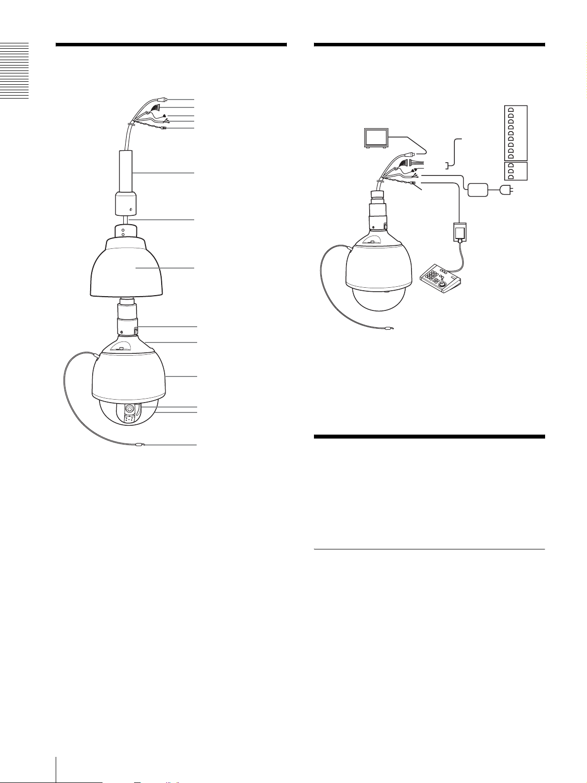
Connections and setup
Outline
1
2
3
4
5
6
7
8
9
0
qa
qs
qd
Monitor
rounding line (black)
larm input line 1 (brown)
larm input line 2 (red)
larm input line 3 (orange)
larm input line 4 (yellow)
larm input line 5 (green)
larm input line 6 (blue)
rounding line (purple)
rounding line (grey)
larm output normal ON (white)
larm output Com (sky-blue)
larm output normal OFF (pink)
Alarm
inputs
Alarm
outputs
RS485
Keypad controller (not
supplied)
GND
Alarm In 1
Alarm In 2
Alarm In 3
Alarm In 4
Alarm In 5
Alarm In 6
GND
GND
Alarm Out Open
Alarm Out Com
Alarm Out Close
AC 24V power adapter
Adapter (not supplied)
qf
Cold Start
1 Composite video cable (BNC cable)
2 Alarm input line
3 Alarm output line
4 AC 24V power cable (with ground line)
5 RS-485 signal line (not supplied with adapter)
6 fastener (not supplied)
7 Cable
8 Sun shield (optional)
9 Connector ring
0 Water-proof cover
qa Main unit
qs lens
qd Water-proof transparent housing
qf Safety cable
6
Component Diagram / Connections and setup / Cold Start
When the camera is started in low temperature, it may
operate improperly due to low inner temperature.
Therefore, cold start operation should be performed if it
is necessary to start the camera in the envionment of –40
to –5 due to blackouts or other reasons.
Cold Start procedures
1
Turn on the power, and turn off the camera after the
heater operates for 1 hour, and then turn off.
2
Turn on the camera again.
Operation Instructions
Scan function
Startup screen: the startup screen will show the software
version, communication protocol, machine address, and
transmission baud rate, etc.
Activate OSD Menu
The method to activate the OSD menu may differ
depending on the connected keypad controller. For a
keypad controller that is compatible with Pelco D
keypad controller, press the number keys “95,” and then
press and hold the “Set Preset” key for 2 seconds to
activate the OSD menu. For other special functions and
key combinations, refer to the table on Page 26.
Horizontal Pan/Vertical Tilt
Manual horizontal pan
Manual horizontal pan must be controlled through the
joystick on the keypad controller. The rotation speed is
adjustable between 0.1° ~ 120°/sec by the position of the
joystick, and the maximum manual horizontal pan speed
is up to 120°/sec.
Auto Scan
Auto scan can be configured to run at startup, or can be
controlled by the keypad controller (for details, see the
table on Page 26).
When the scan range has not been set
The camera will rotate horizontally until a command
from the keypad controller is receivied (e.g., horizontal
rotate, vertical rotate, iris, focus, etc).
When the san range has been set
The camera will rotate horizontally in the scan range
until a command from the keypad controller is received
(e.g., horizontal rotate, vertical rotate, iris, focus, etc).
For details on configuring the scan range, use the menu
command <PAN/TILT SETUP> scan limit stops.
FOCUS
During startup, the lens will zoom out to the minimum
ratio. When auto scanning is controlled by the keypad
controller, original zoom level will be maintained.
Tilt angle
During startup, the camera will perform vertical
scanning according to the tilt angle setting. For details
on configuring the tilt angle, use the menu command
<OTHERS> scan tilt angle. When the keypad controller
issues an auto scanning command, the tilt angle will
remain at the original setting.
Operation Instructions
Manual vertical tilt
Manual vertical tilt speed is adjustable between 0.1° ~
90°/sec, and the speed will be restricted in Proportion
P/T mode.
Horizontal pan range 360° continuous rotation
Vertical tilt range 92°
Manual vertical tilt speed 0.1° ~ 90°/s
Manual horizontal pan speed 0.1° ~ 120°/s
Preset maximum rotation
speed
1) When 92° is used, the unit itself may appear on the
monitoring screen or deformation may appear on the
top of the screen. It is not a malfunction.
At that time, decrease the vertical angle, or zoom in to
eliminate this kind of phenomenon.
1)
Horizontal: 430° /s
Vertical: 200° /s
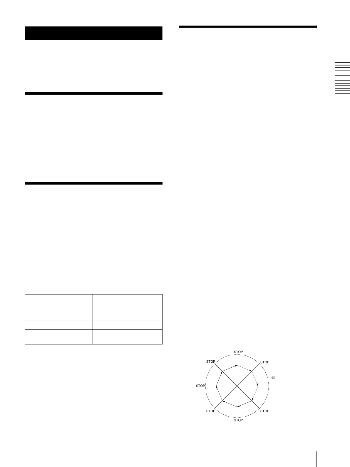
Frame Scanning
Frame scanning can be configured to run at startup, or
can be controlled by the keypad controller (for details,
see the table on Page 26). Configuring the zoom level
and tilt angle is the same as in auto scanning.
When the scan range has not been set
The camera will scan at 45° increments until a command
from the keypad controller is received (e.g., horizontal
rotate, vertical rotate, iris, and focus etc). Refer to the
diagram below.
(stop time)
Activate OSD Menu / Horizontal Pan/Vertical Tilt / Scan function
7
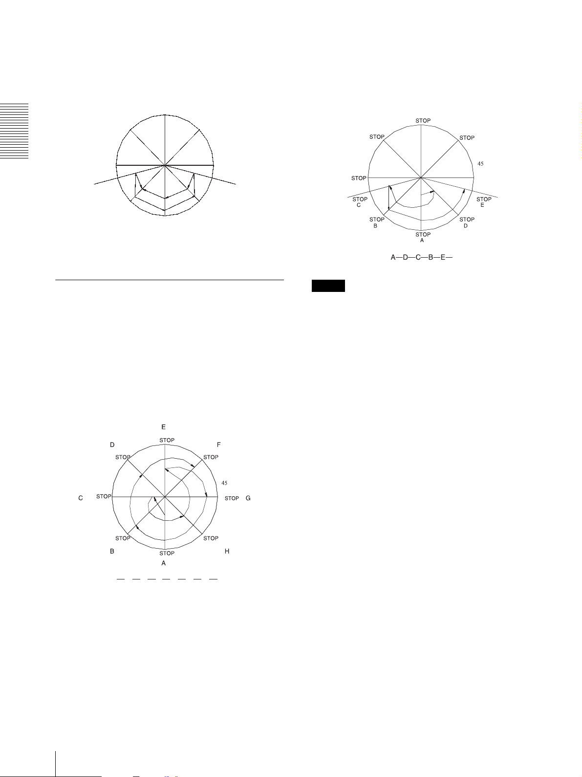
When the scan range has been set
The camera will scan at 45° increments within the scan
range until a command from the keypad controller is
received (e.g., horizontal rotate, vertical rotate, iris,
focus, etc). Refer to the diagram below.
STOP
STOP
Operation Instructions
left limit
STOP
C
STOP
STOP
A
A -->B-->C-->B-->A-->D-->E-->D
STOP
STOP
DB
45
right limit
E
When the scan range has been set
The camera will randomly pick a stop point and perform
scanning in the set range until a command from the
keypad controller is receivied (e.g., horizontal rotate,
vertical rotate, iris, focus, etc). Refer to the diagram
below.
left limit
right limit
Random Scanning
Random scanning can be configured to run at startup, or
can be controlled by the keypad controller (for details,
see the table on Page 26). Configuring the zoom level
and tilt angle is the same as in auto scanning.
When the scan range has not been set
The camera will randomly pick a stop point and perform
scanning until a command from the keypad controller is
receivied (e.g., horizontal rotate, vertical rotate, iris,
focus, etc). Refer to the diagram below.
Note
Please use the menu command <PAN/TILT SETUP>
stop time (p0) to configure the stop time (5 sec to
120 sec).
8
A BCDEFGH
Scan function

Camera Settings
FOCUS
Main menu → <CAMERA SETUP> menu
<FOCUS>
<CAMERA SETUP>
<PAN/TILT SETUP>
<CAMERA TITLE>
<PRESET SETUP>
<OTHERS>
<SYSTEM>
EXIT
WB
<AE>
ZOOM LIMIT
ZOOM SPEED
SHARPNESS
<SYNC LOCK>
PRIVACY ZONE
<ALARM ACTIONS>
BACK
→ <FOCUS> menu
MODE AUTO
ACTIVE TIME ----INTERVAL TIME ----SENSITIVITY NORMAL
BACK
• Focus can be controlled directly by NEAR or FAR
keys.
• One push auto focus feature is equipped.
• Four focus modes are available: Manual, Auto,
Interval, and Zoom.
• In manual focus mode, focus can be controlled
directly by NEAR and FAR keys.
• In auto focus mode, press NEAR or FAR keys to
switch to manual focus mode until the commands for
lens zooming, horizontal, and vertical rotate button
control signals are received.
• In interval mode, the camera will switch between auto
focus and manual focus modes according to the Active
time and Interval Time settings: Active Time →
Interval Time → Active Time → Interval Time….
• Interval and Active time settings range between 0 and
60 seconds.
• In Zoom trigger mode, the camera will remain in
manual focus mode until the control signals for
ZOOM IN or ZOOM OUT are received from the
keypad.
• Auto focus sensitivity can be set to Normal or Low.
Adjust Focus setting options
1
Press “95,” and then hold the PRESET key for
2 seconds to enter the main menu screen.
2
Move the cursor to <CAMERA SETUP>, and then
press the OPEN key to enter the <CAMERA
SETUP> menu.
3
Move the cursor to <FOCUS>, and then press the
OPEN key to enter the option.
P1
ATW
x26
10
OFF
5
4
Move the cursor to <MODE>, and then press the
OPEN key to enter the mode selection menu.
5
Move the joystick up and down to choose the
function to use.
6
Press the OPEN key to confirm, or press CLOSE
to cancel selection and exit from the menu screen.
WHITE BALANCE (WB)
Main menu → <CAMERA SETUP> menu
<FOCUS>
<CAMERA SETUP>
<PAN/TILT SETUP>
<CAMERA TITLE>
<PRESET SETUP>
<OTHERS>
<SYSTEM>
EXIT
WB
<AE>
ZOOM LIMIT
ZOOM SPEED
SHARPNESS
<SYNC LOCK>
PRIVACY ZONE
<ALARM ACTIONS>
BACK
• 6 white balance modes are available: ATW/AUTO/
ONE PUSH WB/INDOOR/OUTDOOR/MANUAL.
• ATW mode: white balance ranges form 2000°K to
10000°K.
• AUTO mode: white balance ranges form 3000°K to
7500°K.
• ONE PUSH WB mode: if you want to use hot key
combination (number “73” +PRESET key) to
perform ONE PUSH WB, the mode must be set to
ONE PUSH WB first., and then ONE PUSH WB
function will be activated.
• INDOOR mode: 3200K is the reference color
temperature.
• OUTDOOR mode: 5800K is the reference color
temperature.
• MANUAL mode: RED and BLUE levels can be
adjusted manually.
Change WB opotions
1
Press “95,” and then hold the PRESET key for
2 seconds to enter the main menu screen.
2
Move the cursor to <CAMERA SETUP>, and then
press the OPEN key to enter the <CAMERA
SETUP> menu.
3
Move the cursor to WB, and then press the OPEN
key to enter the WB mode.
4
Move the joystick up and down to choose the
function to use.
5
Press the OPEN key to confirm, or press CLOSE
to cancel selection and exit from the menu screen.
P1
ATW
x26
10
OFF
5
Operation Instructions
Camera Settings
9

AUTO EXPOSURE (AE)
Main menu → <CAMERA SETUP> menu
Adjust Auto Exposure setting options
1
Press “95,” and then hold the PRESET key for
2 seconds to enter the main menu screen.
<FOCUS>
<CAMERA SETUP>
<PAN/TILT SETUP>
<CAMERA TITLE>
<PRESET SETUP>
<OTHERS>
<SYSTEM>
EXIT
Operation Instructions
WB
<AE>
ZOOM LIMIT
ZOOM SPEED
SHARPNESS
<SYNC LOCK>
PRIVACY ZONE
<ALARM ACTIONS>
BACK
P1
ATW
x26
10
OFF
2
Move the cursor to <CAMERA SETUP>, and then
5
press the OPEN key to enter the <CAMERA
SETUP> menu.
3
Move the cursor to <AE>, and then press the
OPEN key to enter Auto exposure mode.
→ <AE> menu
4
MODE FULL AUTO
AUTO SLOW SHUTTER OFF
SHUTTER SPEED 1/50
IRIS CONTROL AUTO
GAIN CONTROL AUTO
AE COMPENSATION 0
BACK LIGHT COMP OFF
WDR OFF
DAY/NIGHT AUTO
D/N THRESHOLD MID
FLICKERLESS OFF
BACK
• The aperture can be controlled directly by the OPEN
Move the cursor to the desired option, and then
press the OPEN key to enter.
5
Move the joystick up and down to choose the
function to use.
6
Press the OPEN key to confirm, or press CLOSE
to cancel selection and exit from the menu screen.
or CLOSE keys.
• AE mode is ivided into 4 categories: FULL AUTO,
SHUTTER PRIORITY, IRIS PRIORITY and
MANUAL.
• In FULL AUTO mode, the shutter speed is fixed at
1/50 sec (PAL), and the camera will automatically
adjust the aperture according to the amount of outside
light.
• In FULL AUTO mode, the aperture can be manually
controlled; but once the zoom or horizontal pan/
vertical tilt command is received, the camera will
return to FULL AUTO mode.
• In SHUTTER PRIORITY mode, the shutter speed
ranges between 1/1 ~1/10,000 seconds, with 22 steps.
ZOOM LIMIT
• Can b set to wide or tele.
• Zoom levels: 26×, 52×, 104×, 208× and 312×
(SSC-SD26P),
maximum optical zooming: 26×, 52× to 312× is
digital zooming.
• Zoom levels: 36×, 72×, 144×, 288× and 432×
(SSC-SD36P),
maximum optical zooming: 36×, 72× to 432× is
digital zooming.
Main menu → <CAMERA SETUP> menu
• In IRIS PRIORITY mode, the aperture ranges from
F1.6 to CLOSE, with 18 steps.
• AUTO SLOW SHUTTER can be set to either ON or
OFF.
• AE COMPENSATION ranges from –7 to +7.
• BACK LIGHT COMP can be set to eithe r ON or OFF.
It can also be controlled directly by keypad controller
<CAMERA SETUP>
<PAN/TILT SETUP>
<CAMERA TITLE>
<PRESET SETUP>
<OTHERS>
<SYSTEM>
EXIT
<FOCUS>
WB
<AE>
ZOOM LIMIT
ZOOM SPEED
SHARPNESS
<SYNC LOCK>
PRIVACY ZONE
<ALARM ACTIONS>
BACK
P1
ATW
x26
10
OFF
5
(number “71” + PRESET key = ON, number “72” +
PRESET key = OFF).
• WDR can be set to either ON or OFF.
Adjust the Zoom Limit
• DAY/NIGHT mode can be set to aoto or manual.
1
To improve nighttime sensitivity, the infrared filter in
the camera lens can be removed. When set to auto
Press “95,” and then hold the PRESET key for
2 seconds to enter the main menu screen.
mode, the camera will be automatically adjusted
2
according to the environment brightness; in manual
mode, directly press “88” key+ PRESET key
= Daytime color mode; number “89”+ PRESET key
Move the cursor to <CAMERA SETUP>, and then
press the OPEN key to enter the <CAMERA
SETUP> menu.
= Nighttime monochrome mode.
3
• DAY/NIGHT THRESHOLD can be set to HI, MID or
LOW. (available when DAY/NIGHT THRESHOLD
Move the cursor to ZOOM LIMIT, and then press
the OPEN key to enter zoom level selection.
mode is set to aoto mode)
4
• FLICKERLESS: ON and off options are available.
Move the joystick up/down to choose the desired
zoom level.
10
Camera Settings

5
Press the OPEN key to confirm, or press CLOSE
to cancel selection and exit from the menu screen.
2
Move the cursor to <CAMERA SETUP>, and then
press the OPEN key to enter the <CAMERA
SETUP> menu.
ZOOM SPEED
9 steps of zoom speeds are available: 0 ~ 7 steps can be
set by menu; when set to EXT mode, the command has
to be issued through the RS485 interface.
Main menu → <CAMERA SETUP> menu
<FOCUS>
<CAMERA SETUP>
<PAN/TILT SETUP>
<CAMERA TITLE>
<PRESET SETUP>
<OTHERS>
<SYSTEM>
EXIT
WB
<AE>
ZOOM LIMIT
ZOOM SPEED
SHARPNESS
<SYNC LOCK>
PRIVACY ZONE
<ALARM ACTIONS>
BACK
Adjust the Zoom Speed
1
Press “95,” and then hold the PRESET key for
2 seconds to enter the main menu screen.
2
Move the cursor to <CAMERA SETUP>, and then
press the OPEN key to enter the <CAMERA
SETUP> menu.
3
Move the cursor to ZOOM SPEED, and then press
the OPEN key to enter zoom speed selection.
P1
ATW
x26
10
OFF
5
3
Move the cursor to SHARPNESS, and then press
the OPEN key to enter sharpness selection.
4
Move the joystick up/down to choose the
appropriate sharpness.
5
Press the OPEN key to confirm, or press CLOSE
to cancel selection and exit from the menu screen.
SYNC LOCK
The camera can use the power frequency as the source
of synchronous signal
• Signal sync can be set to Line lock or INT.
• The setting range of sync lock phase is 40° ~ 250°.
Set the SYNC LOCK
Main menu → <CAMERA SETUP> menu
<CAMERA SETUP>
<PAN/TILT SETUP>
<CAMERA TITLE>
<PRESET SETUP>
<OTHERS>
<SYSTEM>
EXIT
<FOCUS>
WB
<AE>
ZOOM LIMIT
ZOOM SPEED
SHARPNESS
<SYNC LOCK>
PRIVACY ZONE
<ALARM ACTIONS>
BACK
P1
ATW
x26
10
OFF
5
Operation Instructions
4
Move the joystick up/down to choose the desired
zoom speed.
5
Press the OPEN key to confirm, or press CLOSE
to cancel selection and exit from the menu screen.
SHARPNESS
Sharpness control ranges from 0 to 15 (15 is the
sharpest).
Adjust the Sharpness
Main menu → <CAMERA SETUP> menu
<FOCUS>
<CAMERA SETUP>
<PAN/TILT SETUP>
<CAMERA TITLE>
<PRESET SETUP>
<OTHERS>
<SYSTEM>
EXIT
1
Press “95,” and then hold the PRESET key for
2 seconds to enter the main menu screen.
WB
<AE>
ZOOM LIMIT
ZOOM SPEED
SHARPNESS
<SYNC LOCK>
PRIVACY ZONE
<ALARM ACTIONS>
BACK
P1
ATW
x26
10
OFF
→ <Line lock> menu
MODE INT
PHASE --BACK
1
Press “95,” and then hold the PRESET key for
2 seconds to enter the main menu screen.
2
Move the cursor to <CAMERA SETUP>, and then
press the OPEN key to enter the <CAMERA
SETUP> menu.
3
5
Move the cursor to <Line lock>, and then press the
OPEN key to enter the LINE LOCK selection.
4
Move the cursor to the desired option, and then
press the OPEN key to enter.
5
Move the joystick up/down to choose the
appropriate setting.
6
Press the OPEN key to confirm, or press CLOSE
to cancel selection and exit from the menu screen.
Camera Settings
11

4
PRIVACY ZONE
This feature can enable the user to black out (or white
out) a specifi c portion of the screen to protect the
necessary privacy. The size and position of these frame
Press the OPEN to key to confirm the zone size,
and then go to the setup screen for the zone color:
Screen display: PRIVACY ZONE COLOR
Move the joystick up/down to select the zone color
(black or white).
areas can be adjusted according to the horizontal pan,
5
vertical tilt, and lens zoom of the camera. Up to 24 frame
zones can be configured.
Main menu → <CAMERA SETUP> menu
Operation Instructions
<CAMERA SETUP>
<PAN/TILT SETUP>
<CAMERA TITLE>
<PRESET SETUP>
<OTHERS>
<SYSTEM>
EXIT
<FOCUS>
WB
<AE>
ZOOM LIMIT
ZOOM SPEED
SHARPNESS
<SYNC LOCK>
PRIVACY ZONE
<ALARM ACTIONS>
BACK
P1
ATW
x26
O FF
10
5
Press the OPEN key to confirm the zone color and
then go to the next zone setting screen, or press the
CLOSE key to exit the privacy zone setup mode.
Note
• Up to 24 zones can be setup, but the screen can
simultaneously display 8 zones.
• It is recommended to set the privacy zone slightly
larger than the actual area, to ensure that privacy area
is not revealed during movement.
• Privacy zone will zoom with the lens zoom level to
ensure the effect.
Set Privacy Zone number
ALARM ACTION
1
Press “95,” and then hold the PRESET key for
2 seconds to enter the main menu screen.
2
Move the cursor to <CAMERA SETUP>, and then
press the OPEN key to enter the <CAMERA
SETUP> menu.
3
Move the cursor to PRIVACY ZONE, and then
press the OPEN key to enter privacy zone
selection.
4
Move the joystick up/down to set P1-P24 ON/OFF.
5
Press the OPEN key to confirm, or press CLOSE
to cancel selection and exit from the menu screen.
Set Privacy Zone Size and Position (using
the keypad controller)
1
First move the image to be masked to the center of
the screen.
2
Press number key “83” then press and hold the
PRESET key for 2 seconds to go to the setup
screen for the zone number.
Screen display: PRIVACY ZONE 1
Move the joystick up/down to select the zone
number to set.
There are a set of alarm ports under the camera including
6 alarm inputs and 1 alarm output. Each alarm can be
configured with 209 preset action points, and when
alarm 1 ~ 6 is triggered, the camera will immediately
move to the predefined position.
DETECT TIM: can be set to OFF, 2 seconds, 5 seconds,
10 seconds.
DELAY TIME: the alarm endurance time can be
decided by DELAY TIME (5 ~ 120 seconds).
Main menu → <CAMERA SETUP> menu
<CAMERA SETUP>
<PAN/TILT SETUP>
<CAMERA TITLE>
<PRESET SETUP>
<OTHERS>
<SYSTEM>
EXIT
<FOCUS>
WB
<AE>
ZOOM LIMIT
ZOOM SPEED
SHARPNESS
<SYNC LOCK>
PRIVACY ZONE
<ALARM ACTIONS>
BACK
P1
OFF
ATW
x26
10
5
→ <ALARM ACTIONS> menu
INPUT NO. ACTION OUT
1 OFF OFF
2 OFF OFF
3 OFF OFF
4 OFF OFF
5 OFF OFF
6 OFF OFF
MOTION OFF OFF
DETECT TIME OFF
DELAY TIME 5s
BACK
12
3
Press the OPEN to confirm selection, and then go
to the setup screen for the zone size:
Screen display: PRIVACY ZONE SIZE
Move the joystick up/down to set the zone size.
Camera Settings
 Loading...