

Page 1

4K DIGITAL PROJECTOR
SRX-T615
INSTALLATION MANUAL
1st Edition (Revised 1)
Page 2

!警告
このマニュアルは,サービス専用です。
お客様が,このマニュアルに記載された設置や保守,点検,修理などを行うと感電や火災,
人身事故につながることがあります。
危険をさけるため,サービストレーニングを受けた技術者のみご使用ください。
! WARNING
This manual is intended for qualifi ed service personnel only.
To reduce the risk of electric shock, fi re or injury, do not perform any servicing other than that
contained in the operating instructions unless you are qualifi ed to do so. Refer all servicing to
qualifi ed service personnel.
! WARNUNG
Die Anleitung ist nur für qualifi ziertes Fachpersonal bestimmt.
Alle Wartungsarbeiten dürfen nur von qualifi ziertem Fachpersonal ausgeführt werden. Um die
Gefahr eines elektrischen Schlages, Feuergefahr und Verletzungen zu vermeiden, sind bei
Wartungsarbeiten strikt die Angaben in der Anleitung zu befolgen. Andere als die angegeben
Wartungsarbeiten dürfen nur von Personen ausgeführt werden, die eine spezielle Befähigung
dazu besitzen.
! AVERTISSEMENT
Ce manual est destiné uniquement aux personnes compétentes en charge de l’entretien. Afi n
de réduire les risques de décharge électrique, d’incendie ou de blessure n’effectuer que les
réparations indiquées dans le mode d’emploi à moins d’être qualifi é pour en effectuer d’autres.
Pour toute réparation faire appel à une personne compétente uniquement.
安全のために,周辺機器を接続する際は,過大電圧を持
つ可能性があるコネクターを以下のポートに接続しない
でください。
: NETWORK コネクター
上記のポートについては本書の指示に従ってください。
For safety, do not connect the connector for peripheral device wiring that might have excessive voltage to the following port.
: NETWORK connector
Follow the instructions for the above port.
For kundene i Norge
Dette utstyret kan kobles til et IT-strømfordelingssystem.
SRX-T615
Page 3

Table of Contents
Manual Structure
Purpose of this manual ............................................................ 2 (E)
Related manuals ...................................................................... 2 (E)
Trademarks .............................................................................. 2 (E)
1. Installation
1-1. Outline ....................................................................... 1-1 (E)
1-1-1. Installation Flow .............................................. 1-1 (E)
1-1-2. Required Equipment/Tools ..............................1-2 (E)
1-1-3. External Dimensions ........................................ 1-3 (E)
1-1-4. Installation of Carrying Handle .......................1-5 (E)
1-1-5. Connection ....................................................... 1-9 (E)
1-2. Installation of Duct .................................................. 1-10 (E)
1-3. Installation of Lens .................................................. 1-11 (E)
1-4. Installation of 3D Lens Filter (In the Case of
LKRA-005) .............................................................1-13 (E)
1-5. Installation of Lamp ................................................ 1-16 (E)
1-6. Connection of Power Cord ......................................1-18 (E)
1-7. Adjustment of Projector Tilt ....................................1-20 (E)
2. Adjustment
2-1. SRX Controller .......................................................... 2-1 (E)
2-1-1. Specifi cations of Personal Computer (PC) ......2-1 (E)
2-1-2. Connection ....................................................... 2-1 (E)
2-1-3. Startup ..............................................................2-2 (E)
2-1-4. Control Window ...............................................2-3 (E)
2-1-5. Function Memory ..........................................2-13 (E)
2-1-6. Log Function .................................................. 2-13 (E)
2-2. Setting of This Unit .................................................2-14 (E)
2-2-1. Operation Method of Setting .........................2-14 (E)
2-2-2. Owner Information ........................................2-15 (E)
2-2-3. Network ......................................................... 2-16 (E)
2-2-4. PC Communication ........................................ 2-17 (E)
2-2-5. Profi le ............................................................. 2-18 (E)
2-2-6. Signal Input from Optional Board ................. 2-18 (E)
2-3. Lens Adjustment ......................................................2-19 (E)
2-3-1. Position Adjustment .......................................2-19 (E)
2-3-2. Position Adjustment (Electric Shift
Using SRX Controller) ..................................2-22 (E)
2-3-3. Position Adjustment (Adjusting the
Projector Tilt and Direction) .......................... 2-23 (E)
2-3-4. Brightness Adjustment ...................................2-24 (E)
2-4. Image Adjustment (3D Lens) ..................................2-25 (E)
2-4-1. Optical Axis Adjustment ................................2-25 (E)
2-4-2. 3D Lens Filter Adjustment (In the Case of
LKRA-005) .................................................... 2-27 (E)
2-4-3. Zoom/Focus Adjustment ................................2-29 (E)
2-4-4. Position Adjustment (Adjust Image
Using SRX Controller) ..................................2-30 (E)
2-4-5. Position Adjustment (Adjusting the
Projector Tilt and Direction) .......................... 2-30 (E)
2-4-6.
2-4-7. Image Mapping ..............................................2-33 (E)
2-4-8. Brightness Adjustment ...................................2-34 (E)
2-5. Registration Adjustment .......................................... 2-35 (E)
2-5-1. Fine Adjustment of Registration .................... 2-35 (E)
2-6. Color Space Conversion (CSC Adjustment) ...........2-36 (E)
2-6-1. Correcting the Color Space “sRGB (709)” .... 2-37 (E)
2-6-2. Correcting the Color Space “Single 3D” ....... 2-38 (E)
2-7. Edge Blending Adjustment......................................2-39 (E)
2-7-1. Edge Blending Setting ................................... 2-39 (E)
2-7-2. Correction of Distortion after Edge
Blending Adjustment .....................................2-41 (E)
2-7-3. Color Matching of Edge Blending ................. 2-43 (E)
Alignment of the Horizontal Position of
Image for Right Eye and Image for
Left Eye ..........................................................2-31
(E)
SRX-T615
1 (E)
Page 4

Purpose of this manual
Related manuals
Manual Structure
This manual is the installation manual of 4K Digital Projector SRX-T615.
This manual is intended for use by trained system and service engineers, and describes the information for installation of this unit.
The following manuals are prepared for this unit.
. Safety Regulations (supplied with this unit)
This manual describes the information required to safely use this unit.
. Operating Instructions (available on request)
This manual is necessary for application and operation of this unit.
. Maintenance Manual (available on request)
This manual describes the information about the maintenance of this unit (periodic
check, cleaning, etc.)
Trademarks
. Service Manual (available on request)
This manual describes the information that premise the service based on part replacement of this unit.
Trademarks and registered trademarks used in this manual are follows.
. The terms HDMI and HDMI High-Defi nition Multimedia Interface, and the HDMI
Logo are trademarks or registered trademarks of HDMI Licensing LLC in the
United States and other countries.
. Windows and Windows Vista are the registered trademarks of Microsoft Corpora-
tion in the United States and Other countries.
. Ethernet is a registered trademark of Xerox Corporation.
Other system names, product names, and company names appearing in this manual
are trademarks or registered trademarks of their respective holders.
2 (E)
SRX-T615
Page 5
Section 1
Installation
1-1. Outline
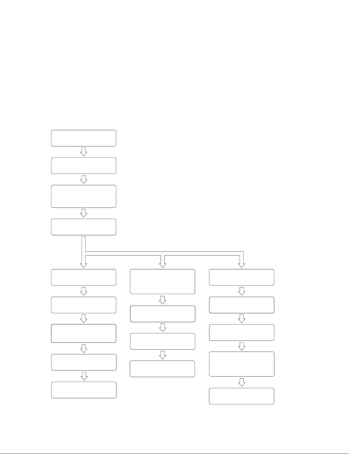
1-1-1. Installation Flow
The installation procedure for this unit is shown in the flow chart.
For the details of each flow, refer to the corresponding item.
n
Basically there is no problem even if Sections 1-2 to 1-5 are not performed in sequential order. However,
do not connect the power cord in Section 1-6 before Sections 1-2 to 1-5 are completed.
Start the installation.
. 1-2. Installation of Duct
Install this unit.
Install the SRX Controller in a
personal computer (PC).
(Refer to the Operating
Instructions.)
. 1-3. Installation of Lens
. 1-4. Installation of 3D Lens Filter (In the Case of LKRA-005)
. 1-5. Installation of Lamp
. 1-6. Connection of Power Cord
. 1-7. Adjustment of Projector Tilt
Set this unit.
(Refer to Section 2-2.)
Only a 2D lens
is used.
Perform lens adjustment.
(Refer to Section 2-3.)
Perform registration adjustment.
(Refer to Section 2-5.)
Perform gamma and uniformity
adjustments using a Projector
Color Adjustment Tool.
Perform color space
correction (CSC adjustment).
(Refer to Section 2-6.)
Perform edge blending
adjustment.
(Refer to Section 2-7.)
n
Perform gamma and uniformity adjustments before
installation when using only a 3D lens.
Only a 3D lens
is used.
Perform gamma and uniformity
adjustments using a Projector
Color Adjustment Tool with the
2D lens installed.
Install the 3D lens, then
perform image adjustment.
(Refer to Section 2-4.)
Perform registration adjustment.
(Refer to Section 2-5.)
Perform color space
correction (CSC adjustment).
(Refer to Section 2-6.)
2D and 3D
lenses are used.
Perform lens adjustment.
(Refer to Section 2-3.)
Perform image adjustment.
(Refer to Section 2-4.)
Perform registration adjustment.
(Refer to Section 2-5.)
Perform gamma and uniformity
adjustments using a Projector
Color Adjustment Tool with the
2D lens installed.
Perform color space
correction (CSC adjustment).
(Refer to Section 2-6.)
SRX-T615
1-1 (E)
Page 6

1-1-2. Required Equipment/Tools
The equipment and tools required for this unit are as follows.
Equipment/tools Description
Projection lens Prepare the necessary lens(es) in accordance with the installation
environment.
. LKRL-Z511
. LKRL-Z514
. LKRL-Z519
. LKRL-A502
. LKRL-A503
t
Regarding the selection of lens, contact your local Sony Sales Office/Service Center.
3D lens filter LKRA-005 etc.
Lamp Prepare one of the following lamps in accordance with the installation environment.
. LKRM-U450 (6 pcs, 450 W)
. LKRM-U330 (6 pcs, 330 W)
t
. If all 6 pcs are not inserted, this unit does not operate.
. Regarding the selection of lamp, contact your local Sony Sales Office/Service
Center.
Power cable Need to obtain the cable that matches the plug on the installation site.
LAN cable or RS-232C cable For personal computer connection
Exhaust system Connect the duct to the duct connecting portion on the rear top panel for exhausting
the heat inside this unit. In the case of using the 8-inch duct, the following exhaust air
volume is required.
The exhaust air volume of 450-550 ft
HDMI cable For External reproduction device connection (Refer to “1-1-5. Connection”)
Tool Screwdriver (for installing the lamp)
Carrying handle Handle arm (part number: 4-164-849-02)
Pipe (short) (part number: 4-164-850-02)
Pipe (long) (part number: 4-164-851-02)
Luminance meter CL-200 or the equivalent
Colorimeter PR-650 or the equivalent
Tripod For the colorimeter and illuminometer
Hexagonal wrench For the 3D lens adjustment: subtense: 2.5, 3.0, 5.0 mm
For the lens shift adjustment: subtense: 5.0 mm
Spanner Subtense: 8 mm (supplied with the lens)
Subtense: 24 mm (for flexible leveler)
Subtense: 30 mm (for nut (M20))
Personal computer (PC) For SRX Controller connection
For detail, refer to Section 2-1-1.
3
/min (12.7 to 15.6 m3/min) should be secured.
1-2 (E)
SRX-T615
Page 7
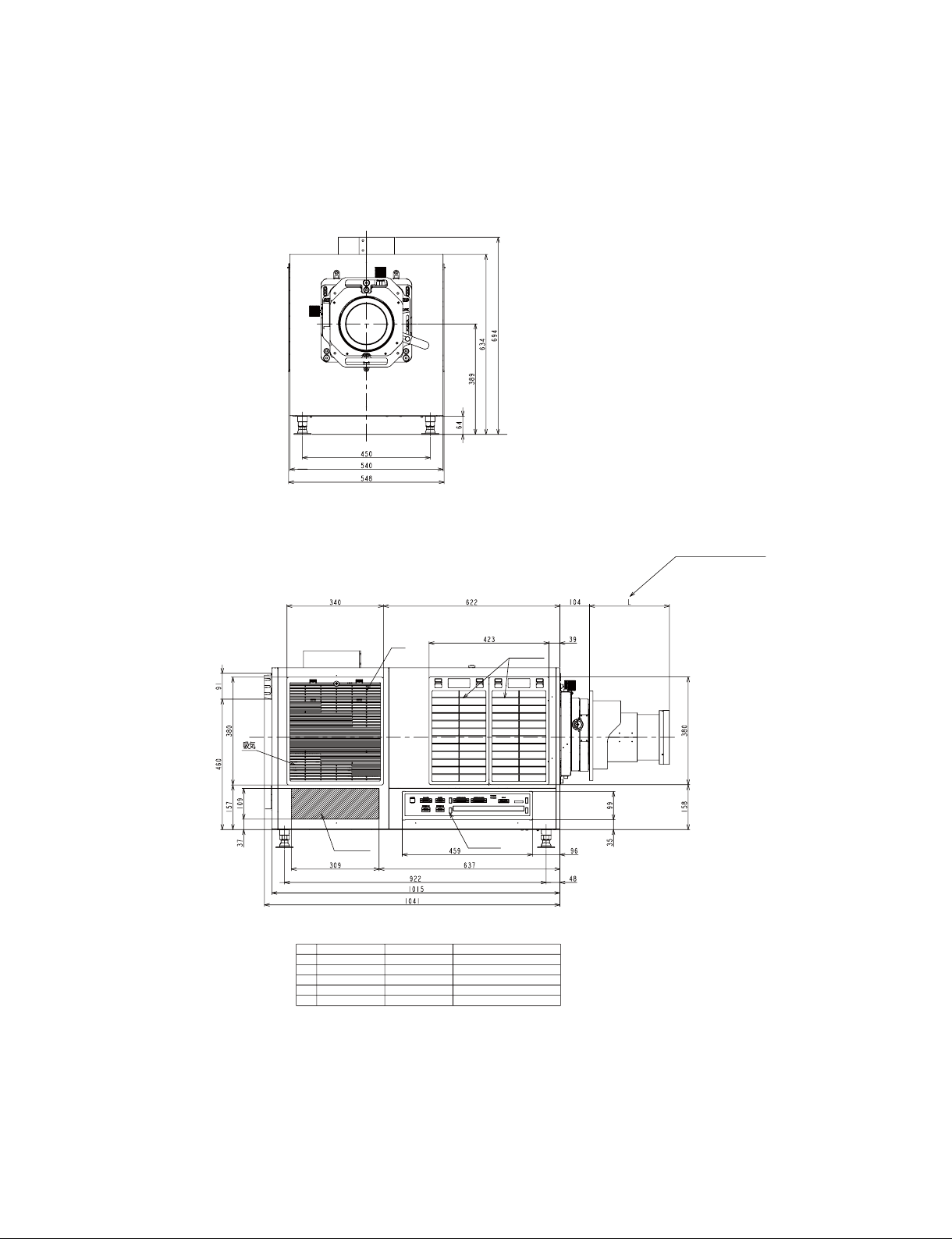
1-1-3. External Dimensions
Front view
Left side view
Air
Intake
Heat
exhaust
*
LKRL LIST
No. LKRL L REMARKS
1 Z511 258-297
2 Z514 230-283
3 Z519 244
4 A502 462 Including in 3D lens filter
5 A503 462 Including in 3D lens filter
Air Intake
Input/output
terminal
*
(Refer to the optional
lens list.)
SRX-T615
1-3 (E)
Page 8
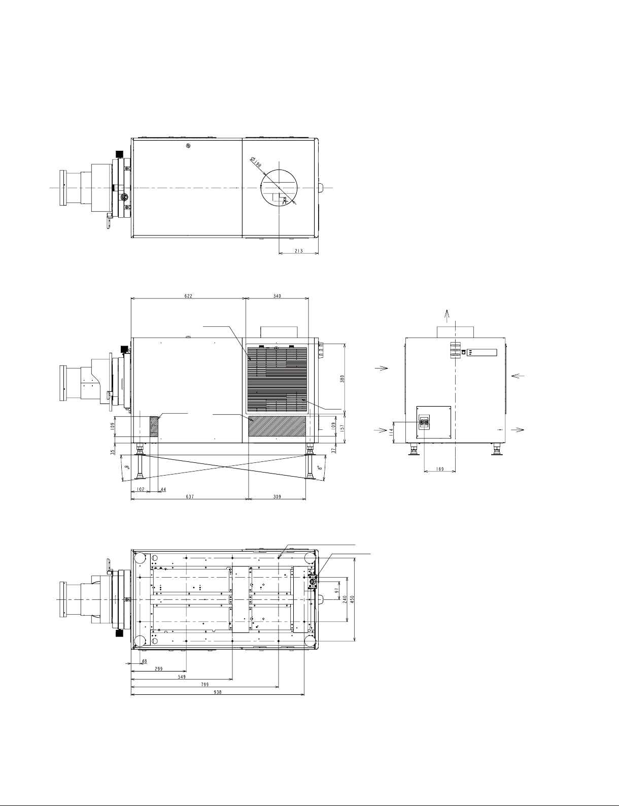
Top view
Right side view Rear view
Bottom view
Air Intake
Air Intake
Air Intake
Air
Intake
10-M8 (for fixing the projector)
AC power cable
Air Intake
Air Intake
Heat exhaust
Air Intake
Heat exhaust
1-4 (E)
Unit: mm
SRX-T615
Page 9

1-1-4. Installation of Carrying Handle
When moving this unit to the pedestal after unpacking, attach the carrying handles as required for transporting it.
n
The carrying handles cannot be attached to both back/forth and right/left at the same time.
Parts information
. Handle arm: 4-164-849-02: 4 pcs
. Pipe (short): 4-164-850-02: 2 pcs
. Pipe (long): 4-164-851-02: 2 pcs
. M8 bolt: 2-590-262-02 or -11: 4 pcs
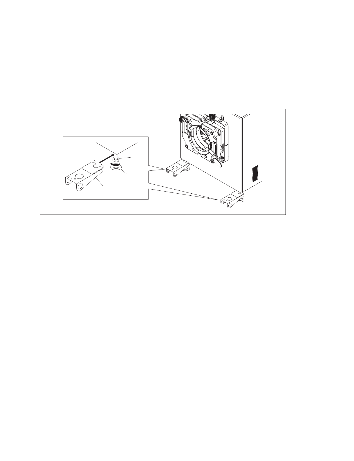
In the case of attaching the pipe (long) to the right and left side of this unit
1. Loosen the nut in the direction of the arrow A, then insert the handle arm in the direction of the
arrow B.
2. Tighten the nut to fix the handle arm.
3. Attach the handle arm to the adjuster of other three portions by repeating steps 1 and 2.
SRX-T615
Nut
A
Adjuster
B
Handle arm
1-5 (E)
Page 10
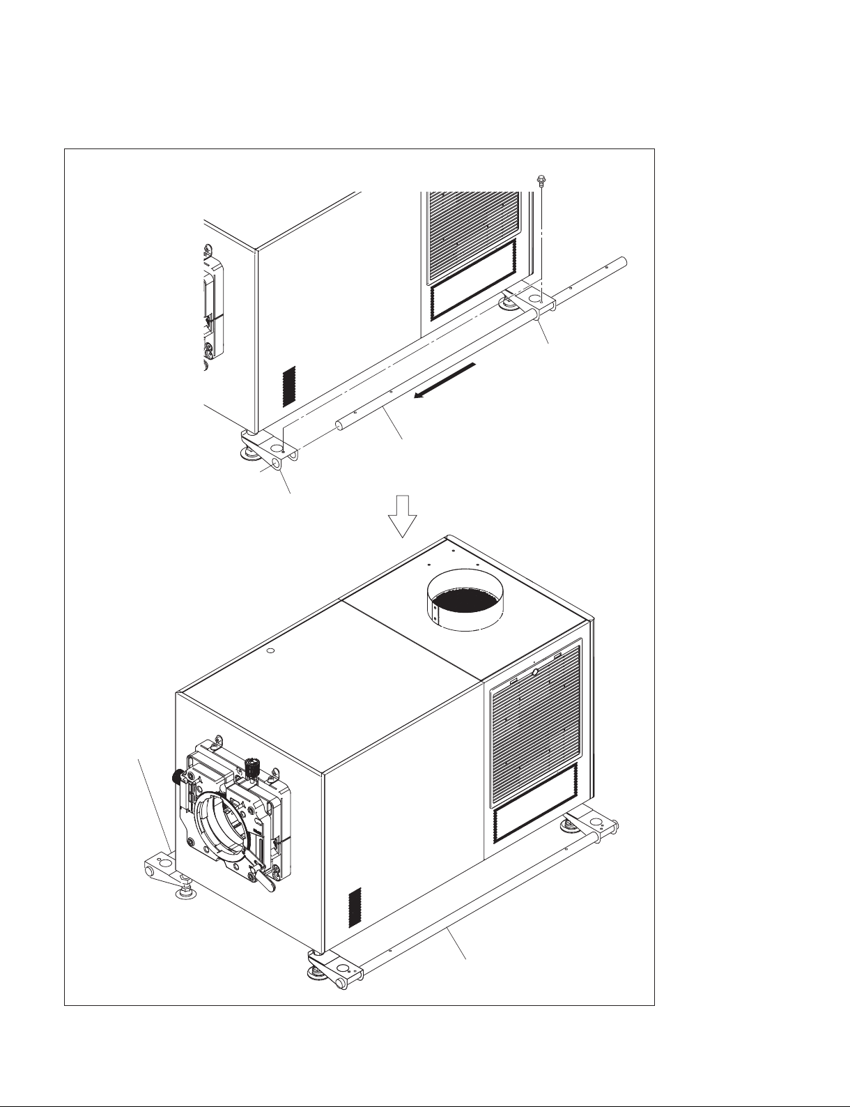
4. Insert the pipe (long) into the handle arms, then fix the pipe with the two M8 bolts.
5. Attach the pipe (long) on the other side in the same way.
M8 bolts
Handle arm
Pipe (long)
Handle arm
Pipe (long)
1-6 (E)
Pipe (long)
SRX-T615
Page 11
In the case of attaching the pipe (short) to the back and forth of this unit
t
The procedure is the same as the pipe (long).
1. Loosen the nut in the direction of the arrow A, then insert the handle arm in the direction of the
arrow B.
2. Tighten the nut to fix the handle arm.
3. Attach the handle arm to the adjuster of other three portions by repeating steps 1 and 2.
B
Handle arm
Nut
A
Adjuster
SRX-T615
1-7 (E)
Page 12
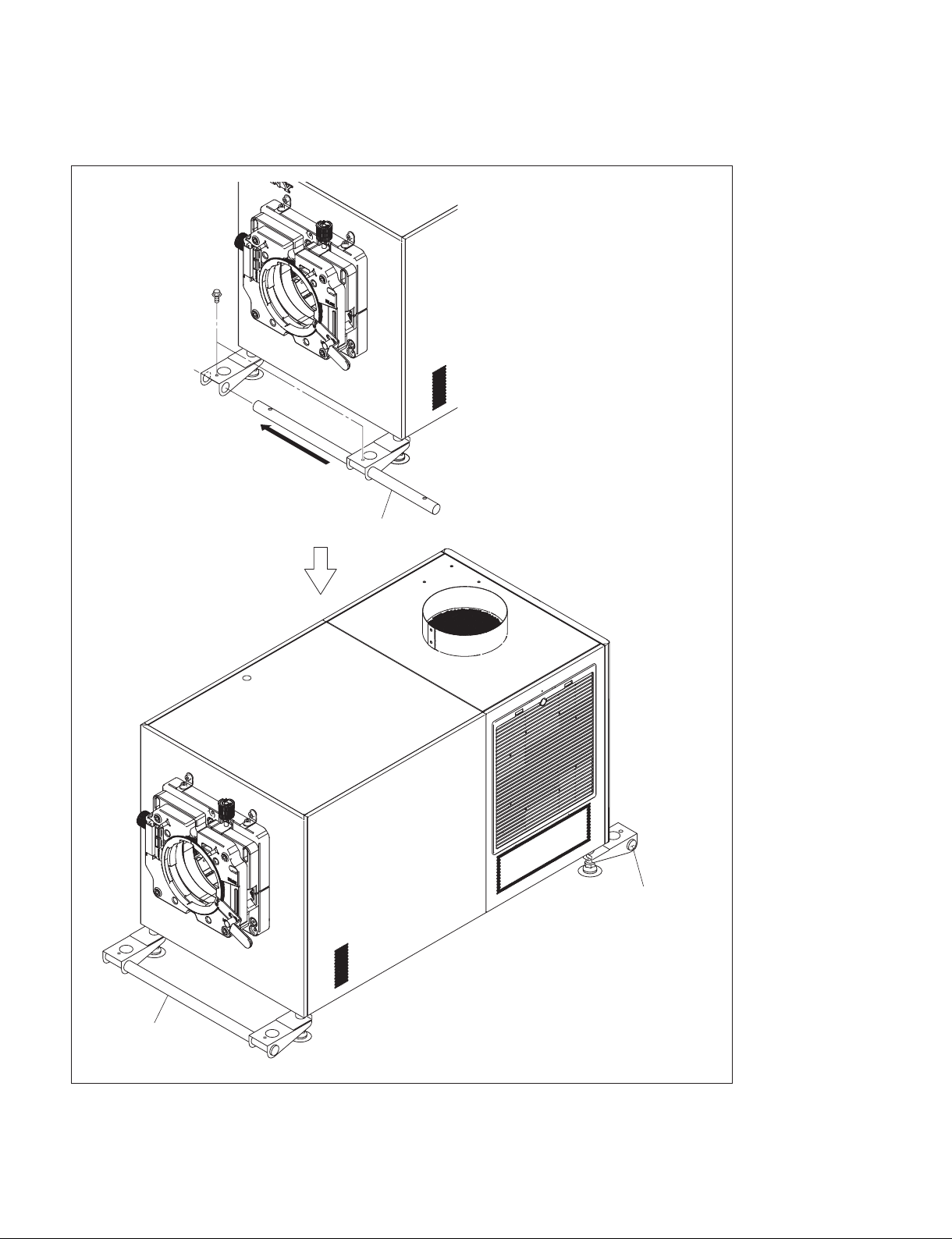
4. Insert the pipe (short) into the handle arms, then fix the pipe with the two M8 bolts.
5. Attach the pipe (short) on the other side in the same way.
M8 bolts
Pipe (short)
1-8 (E)
Pipe (short)
Pipe (short)
SRX-T615
Page 13
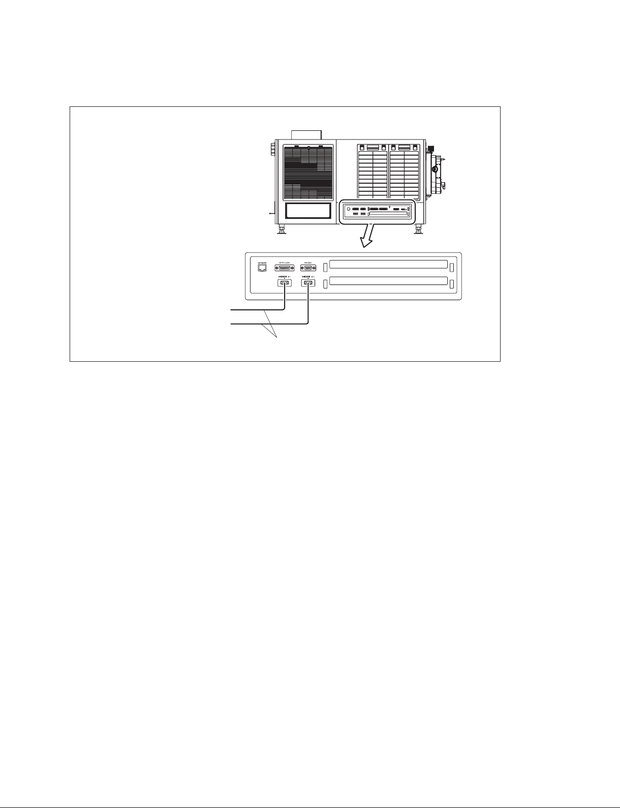
1-1-5. Connection
External reproduction device
External reproduction device
Left side of this unit
HDMI cable
SRX-T615
1-9 (E)
Page 14
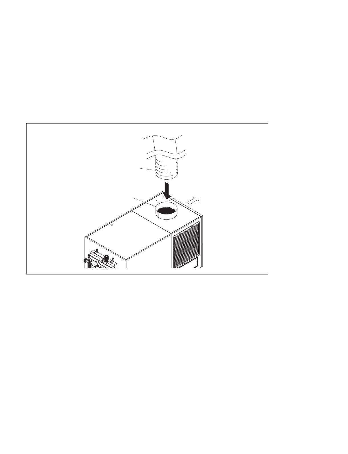
1-2. Installation of Duct
n
Basically there is no problem even if Sections 1-2 to 1-5 are not performed in sequential order. However,
do not connect the power cord in Section 1-6 before Sections 1-2 to 1-5 are completed.
Attach the 8-inch duct to the duct connecting portion on the rear side of the top portion of this unit.
n
. When attaching the duct, be careful not to bend the duct for exhausting the air smoothly.
. For the required exhaust air volume, refer to “1-1-2. Required Equipment/Tools”.
8-inch duct
Duct connecting portion
Rear side
1-10 (E)
SRX-T615
Page 15
1-3. Installation of Lens
n
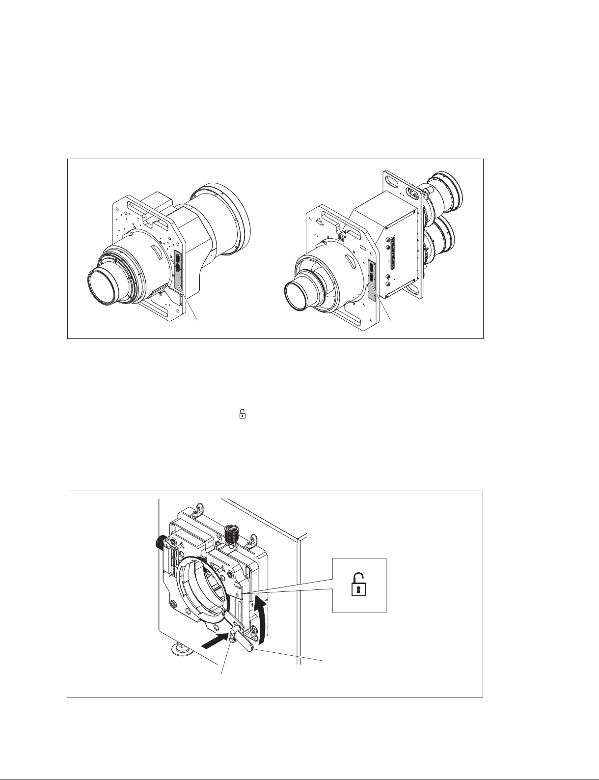
. When performing the installation/removal of lens, be sure to shut down this unit by the SRX Controller,
then turn off the power switch on the rear side of this unit.
. When performing the installation/removal of lens, be careful not to touch the lens board.
3D lens2D lens
Board
Board
t
Although the illustration used here for description is the 2D lens, the installation procedure for the 3D lens
is the same as the 2D lens.
1. Raise the lens fixing lever toward the “ ” side with the lock button pushed all the way in (lock
released).
n
If you raise the lens fixing lever without pushing the lock button, the lock button and lens fixing lever
will be damaged. Be sure to push the lock button and check that the lock is released before raising the
lever.
SRX-T615
Lens fixing lever
Lock button
1-11 (E)
Page 16
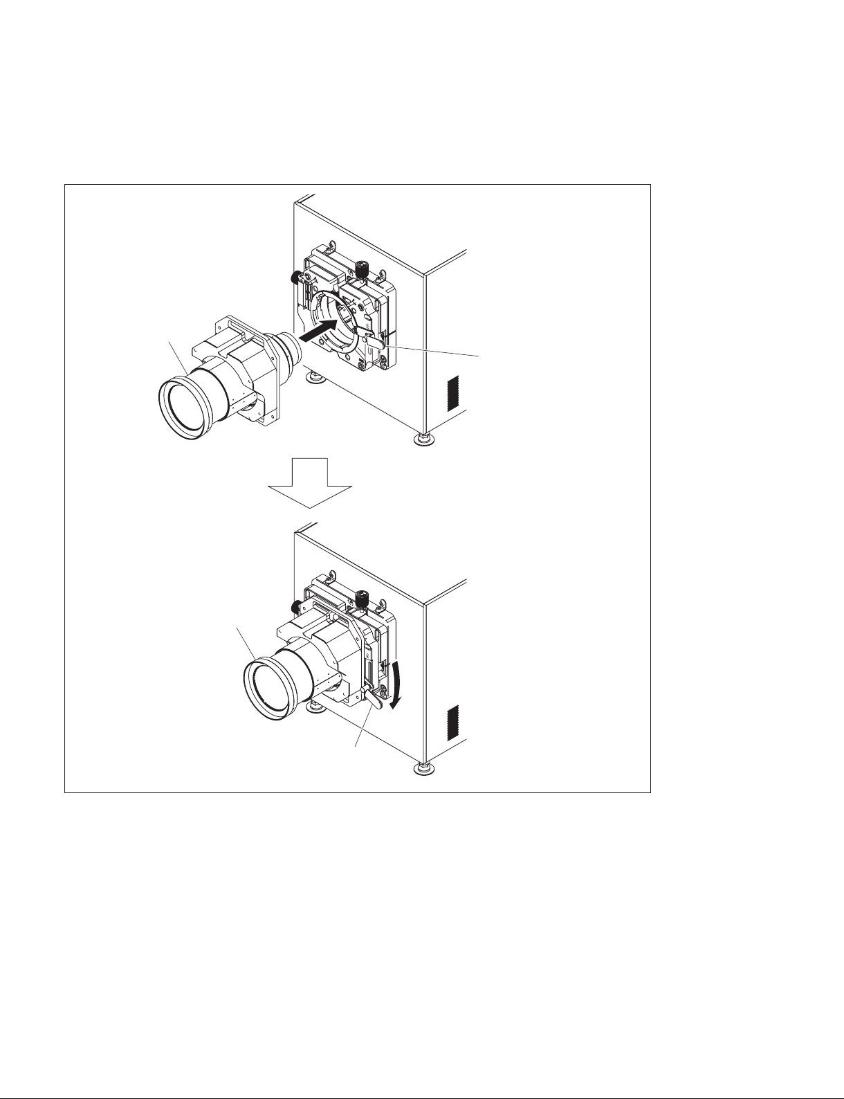
2. Attach the lens to this unit while firmly holding the lens not to drop it and aligning the position.
n
When attaching the lens to this unit, insert it straight.
3. Lower the lens fixing lever to fix the lens.
Lens
Lens fixing lever
Lens
Lens fixing lever
1-12 (E)
SRX-T615
Page 17
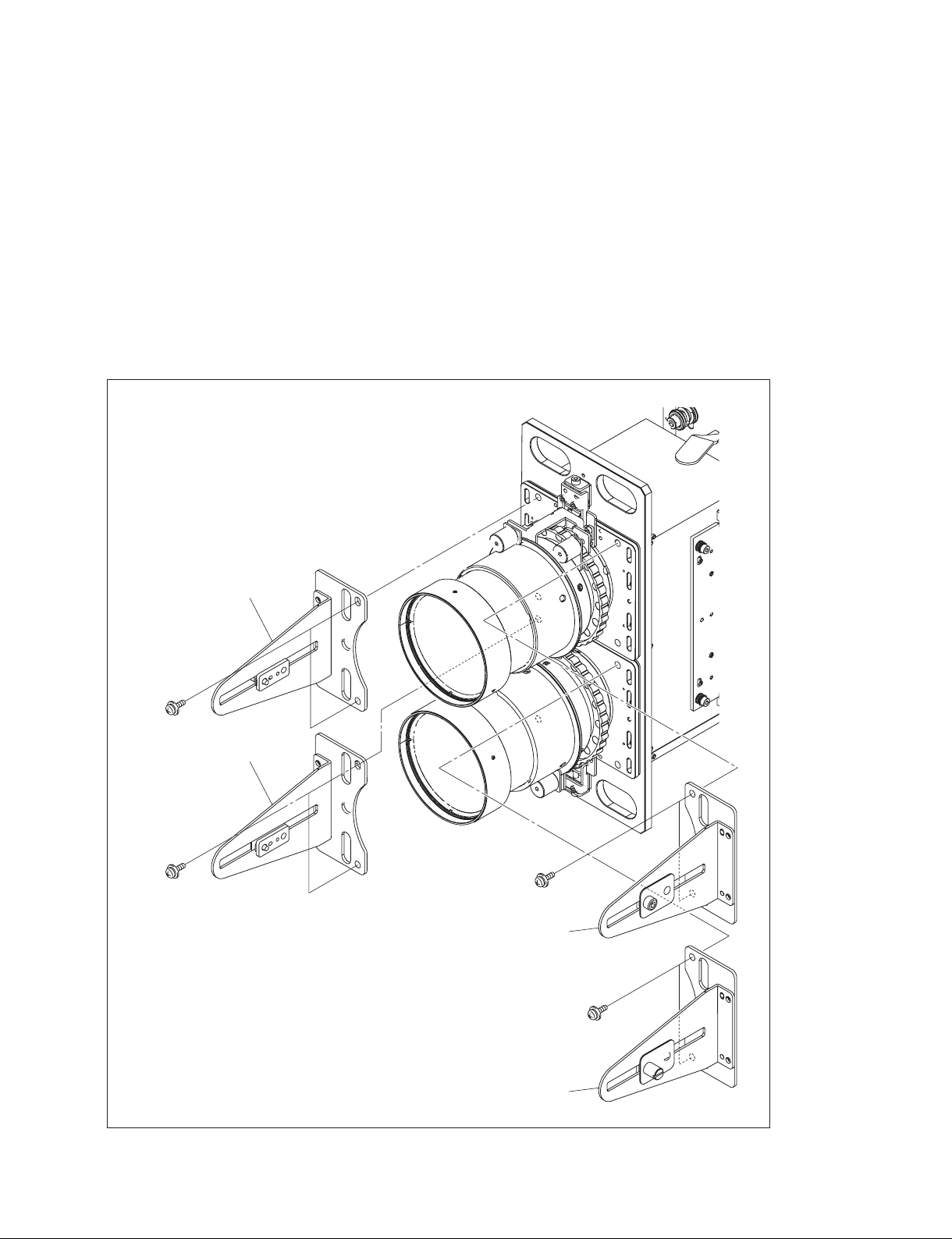
1-4. Installation of 3D Lens Filter (In the Case of LKRA-005)
n
In the LKRA-005 Installation Manual, the procedure for installing LKRA-005 in SRX-R320S is described. When installing LKRA-005 in this unit, follow the procedure in this manual.
n
. Be careful not to attach the filter bracket (A)/(B) assemblies in the wrong position.
. Attach the knob securely to prevent the lens filter from dropping.
1. Attach the three filter bracket (A) assemblies with the six screws supplied with the 3D lens filter.
2. Attach the filter bracket (B) assembly with the two screws supplied with the 3D lens filter.
Filter bracket (A) assembly
PSW6 x 8
Filter bracket (A) assembly
PSW6 x 8
PSW6 x 8
Filter bracket (A) assembly
PSW6 x 8
SRX-T615
Filter bracket (B) assembly
1-13 (E)
Page 18
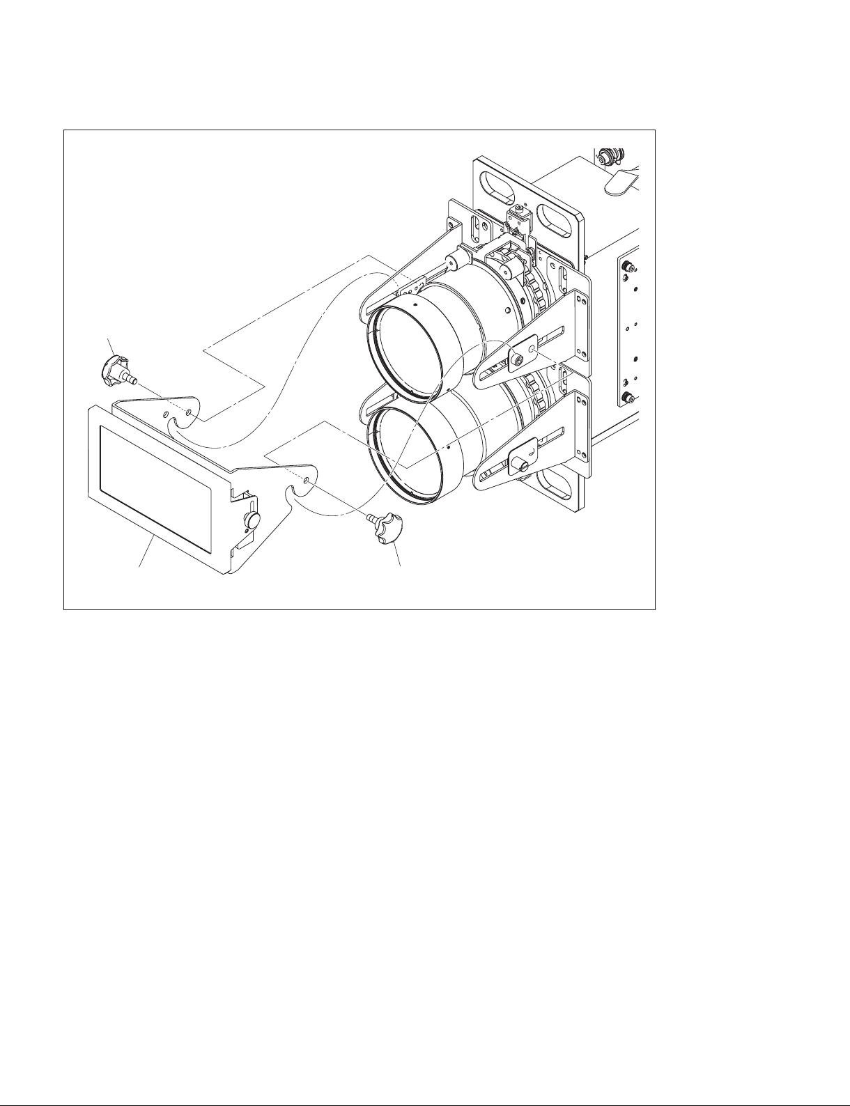
3. Attach the 3D filter (R) assembly with the two knobs.
Knob
3D filter (R) assembly
Knob
1-14 (E)
SRX-T615
Page 19
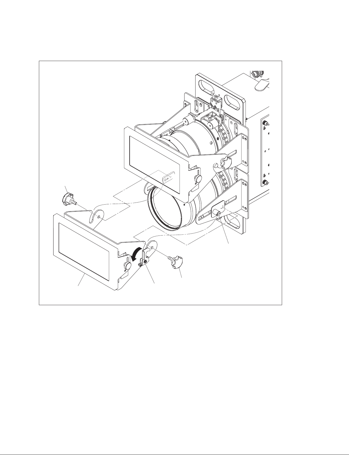
4. Release the lock plate in the direction of the arrow, then hook it on the position pin.
5. Attach the 3D filter (L) assembly with the two knobs.
Knob
3D filter (L) assembly
Position pin
Knob
Lock plate
SRX-T615
1-15 (E)
Page 20
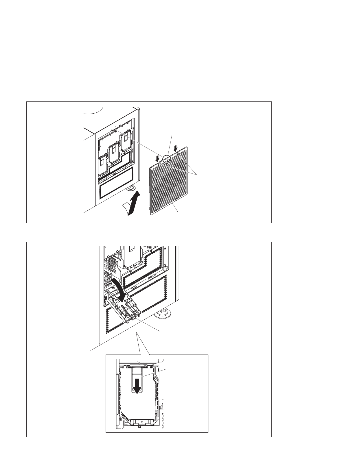
1-5. Installation of Lamp
n
For safety, always wear gloves when performing installation.
1. Loosen the screw (with drop-safe), lower the two hooks, and then remove the intake grille (A) in the
direction of the arrow A.
Screw (with drop-safe)
Hooks
A
2. Lower the lamp door latch to open the lamp door.
Intake grille (A)
Lamp door
Lamp door latch
1-16 (E)
SRX-T615
Page 21
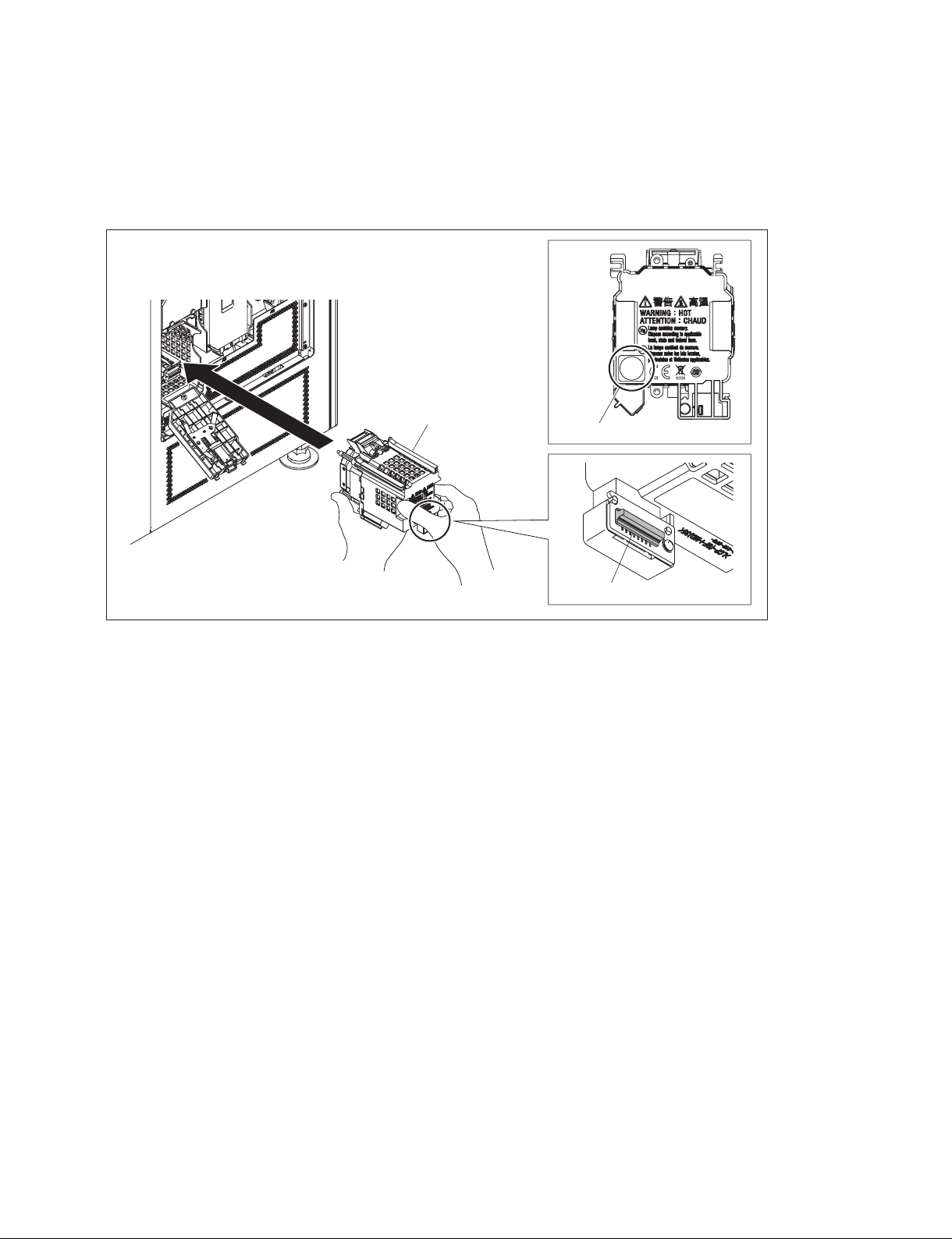
3. Insert the lamp and close the lamp door.
n
. When holding the lamp, be careful not to touch the connector contact portion.
. Push near the PUSH mark of the lamp to insert it securely.
4. Attach the remaining lamps by repeating steps 2 and 3.
PUSH
Lamp
5. To install the intake grille (A), reverse the removal procedure.
PUSH mark
Connector contact portion
SRX-T615
1-17 (E)
Page 22
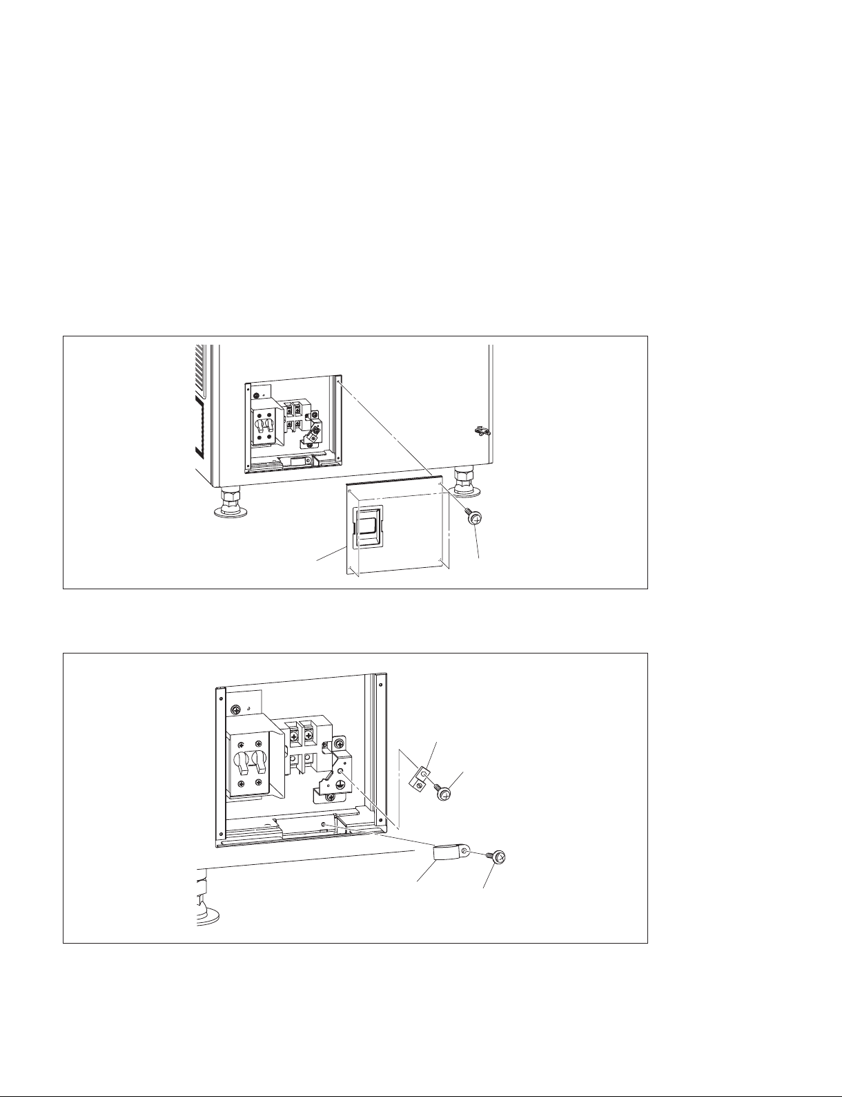
1-6. Connection of Power Cord
Use the 3-core power cord that satisfies AWG 8, 250 V rated and 40 A rated or more.
Connect the power cord to the AC IN terminal block on the rear side of this unit in the following procedure.
w
. Connection of the main power and the electric wiring work should be done by qualified electricians only.
. Do not plug the power cord into the power supply before completing all of the following connecting
operations.
1. Remove the four screws, then remove the terminal block cover.
Terminal block cover
2. Remove the screw, then remove the cable clamp.
3. Remove the screw, then remove the ground terminal.
Ground terminal
Cable clamp
Screws
Screw
Screw
1-18 (E)
SRX-T615
Page 23
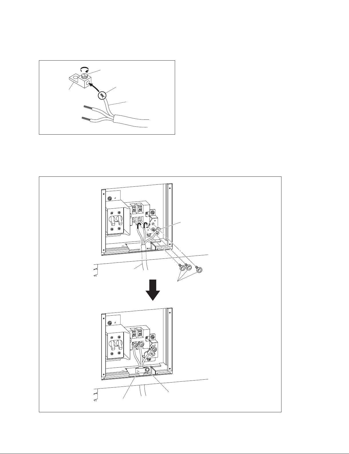
4. Apply solder to the end of the ground wire.
5. Attach the ground terminal removed in step 3 to the ground wire, then fix it with the screw.
Screw
Apply solder.
Ground terminal
Ground wire
6. Route the power cord through the hole on the bottom of the terminal block, then fix each terminal
with the screw as shown in the illustration.
7. Fix the power cord using the cable clamp and screw.
8. Attach the terminal block cover.
Power cord
Ground terminal
Screws
SRX-T615
Screw
Cable clamp
1-19 (E)
Page 24
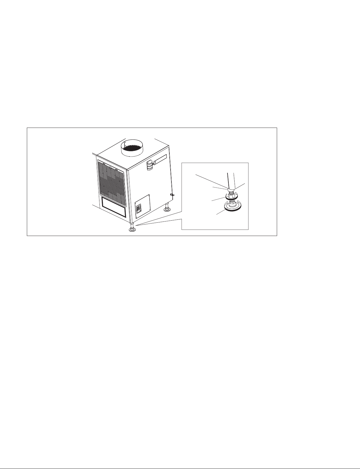
1-7. Adjustment of Projector Tilt
n
The tilt adjustment of this unit is performed when adjusting the image position and so on.
1. Loosen the nut.
2. Adjust the projector tilt by rotating the adjuster.
. Rotate clockwise direction (2): To raise the height of this unit
. Rotate counterclockwise direction (3): To lower the height of this unit
3. Fix the adjuster by tightening the nut toward the adjuster pipe.
Example of tilted projector
Adjuster pipe
Nut
Adjuster
1-20 (E)
SRX-T615
Page 25
Section 2
Adjustment
2-1. SRX Controller
This unit can be operated the adjustments and setting using the supplied SRX Controller.
For about installation of SRX Controller, refer to the Operating Instructions.
2-1-1. Specifications of Personal Computer (PC)
. PC Intel Pentium M 1.6 GHz or more, and OS-recommended CPU
- RAM capacity: 256 MB or more, 512 MB or more recommended, and OS-recommended
- Communication: LAN (10BASE-T/100BASE-T) or COM (RS-232C)
- Graphics mode: XGA (1024 x 768) or higher
- HDD: Built-in Drive, having an empty capacity of 15 MB or more
. OS: Microsoft Windows Vista Business SP2 (English or Japanese version, except for x64 Edition) or
Windows 7 Enterprise SP1 (English or Japanese version)
n
Microsoft Windows XP support has ended. Do not connect PC on which Windows XP is installed
to the projector.
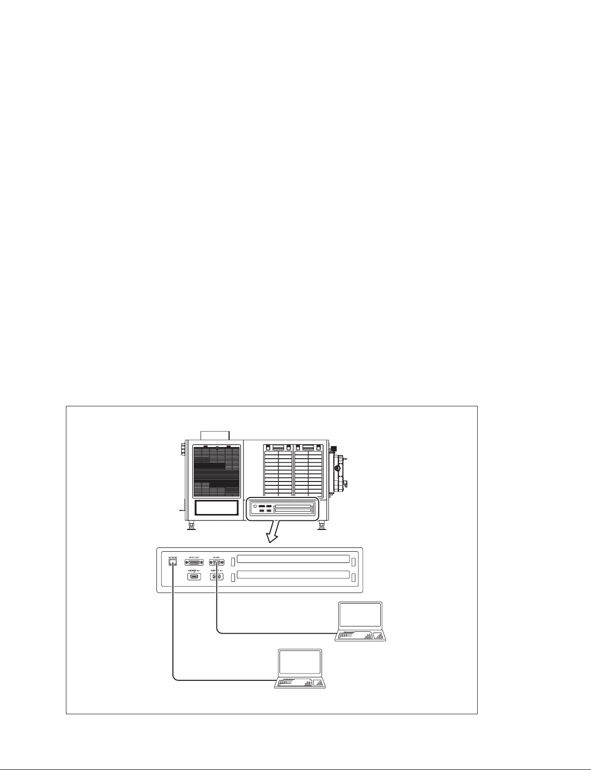
2-1-2. Connection
Connect this unit and PC using a LAN cable or RS-232C cable.
Left side of this unit
When connecting using an
RS-232C cable (cross cable)
When connecting using
a LAN cable
PC
SRX-T615
PC
2-1 (E)
Page 26
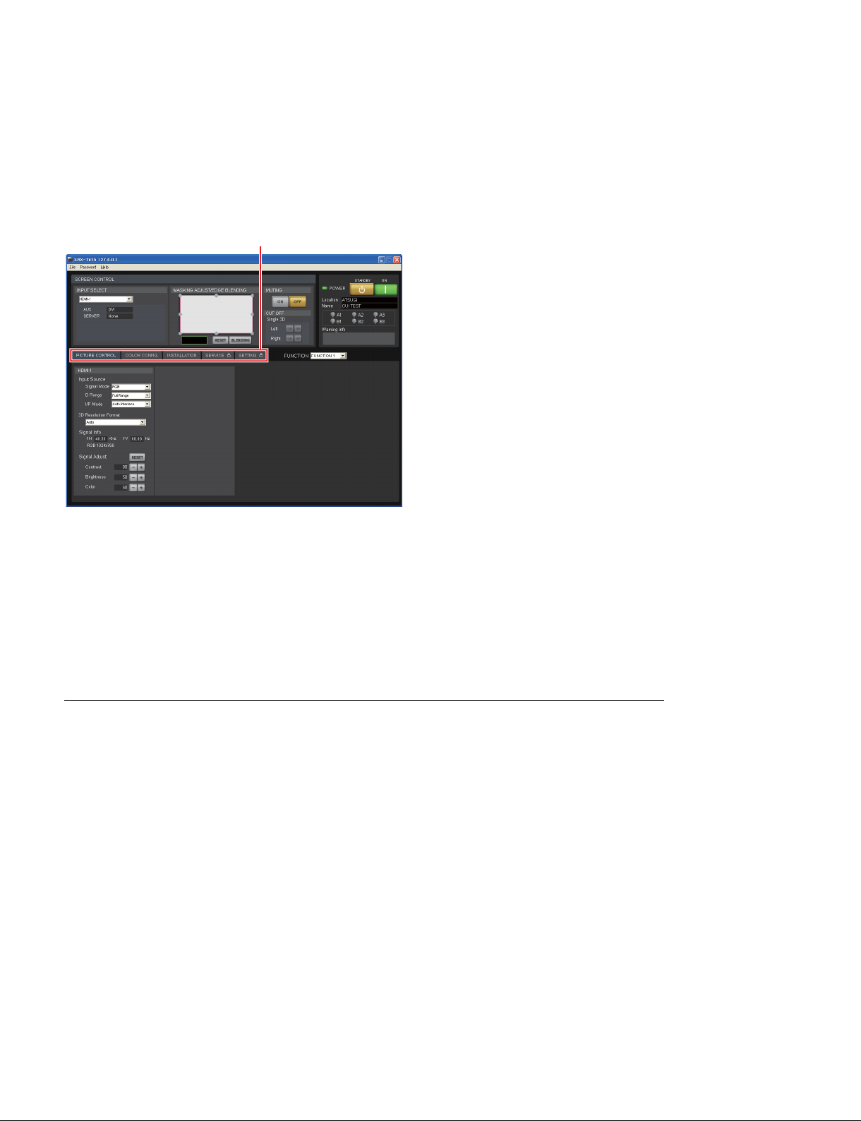
2-1-3. Startup
1. Connect this unit and PC. (Refer to Section 2-1-2.)
2. Install SRX Controller. (Refer to the Operating Instructions.)
3. Start the SRX Controller. (Refer to the Operating Instructions.)
Screen example
Menu tab
4. Click the menu tab to display the menu screen that you want to open.
5. If you want to display the [SERVICE] screen or the [SETTING] screen, type the password in the
password entering window and click the [OK] button.
Password (Initial setting)
. [SERVICE] screen: service
. [SETTING] screen: setting
n
Type the password using the lowercase characters.
To exit the menu
Select “Quit” from the [File] menu.
2-2 (E)
SRX-T615
Page 27
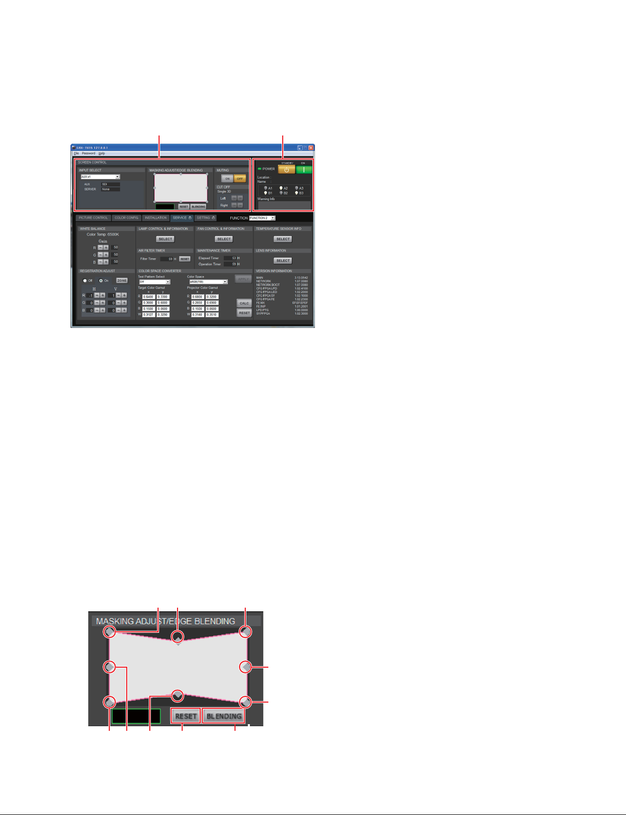
2-1-4. Control Window
1. Common Items
Screen example
1
1 [SCREEN CONTROL]
2 Status
POWER/Location/Name/Lamp status/Warning Info
2
1 [SCREEN CONTROL]
. [INPUT SELECT]
Selects the input signal to be output as video signal.
- “HDMI-1”: Internal HDMI input
- “HDMI-2”: Internal HDMI input
- “AUX x1”: Option board 1 input
- “AUX x4”: Option board 4 input
- “Single 3D HDMI-1(L/R)”: 3D mode
- “Single 3D HDMI-2(L/R)”: 3D mode
- “Single 3D HDMI-1(L)/2(R)”: 3D mode
. [MASKING ADJUST/EDGE BLENDING]
Adjusts the image masking according to the screen shape by the eight adjusting point respectively.
And adjustment value is displayed by pointing the cursor at each adjusting point ((1) to (8)).
Screen example
(1) (5) (2)
(8)
SRX-T615
(3) (7) (6)
[RESET]
button
[BLENDING]
(4)
button
2-3 (E)
Page 28
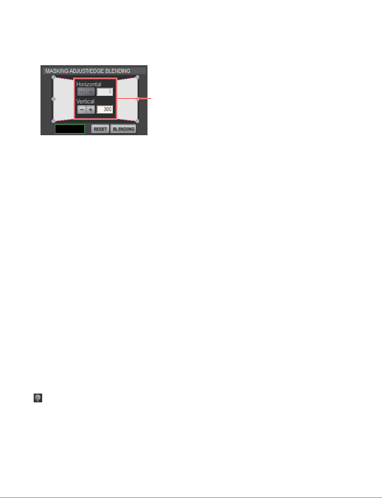
When an adjusting point is double-clicked, the adjustment screen is displayed.
Screen example
Adjustment screen
A setting value increases when you click the [+] button. A setting value decreases when you click the
[_] button. The numeric value can also be entered directly.
Each setting value is as follows:
(1) to (4) H: 0 to 2047
V: _1023 to 1023
(5), (6) V: _511 to 511
(7), (8) H: _511 to 511
All items in a [MASKING ADJUST/EDGE BLENDING] are returned to the factory setting when
you click the [RESET] button.
The blending adjustment screen is displayed when you click the [BLENDING] button. (MAIN
version 3.19.0600 or later)
For details, refer to Section 2-7.
. [MUTING]
Operates to close and open of the douser.
- [ON] button: Close the douser. (Muting condition)
- [OFF] button: Open the douser.
. [CUT OFF]
When a 3D lens is attached, switch the output of image for right eye and left eye.
2 Status (POWER/Location/Name/Lamp status/Warning Info)
. [POWER]
- [STANDBY] button: Puts this unit into the standby state. (Canceled using an [ON] button.)
- [ON] button: Turns on the power.
. Location: Displays the location.
. Name: Displays the owner name.
(Lamp bulb): The color changes according to the time of the lamp used.
.
0% to 80%: White
80% to 100%: Yellow
100% or more: Red
. Warning Info: Displays warning information.
2-4 (E)
SRX-T615
Page 29
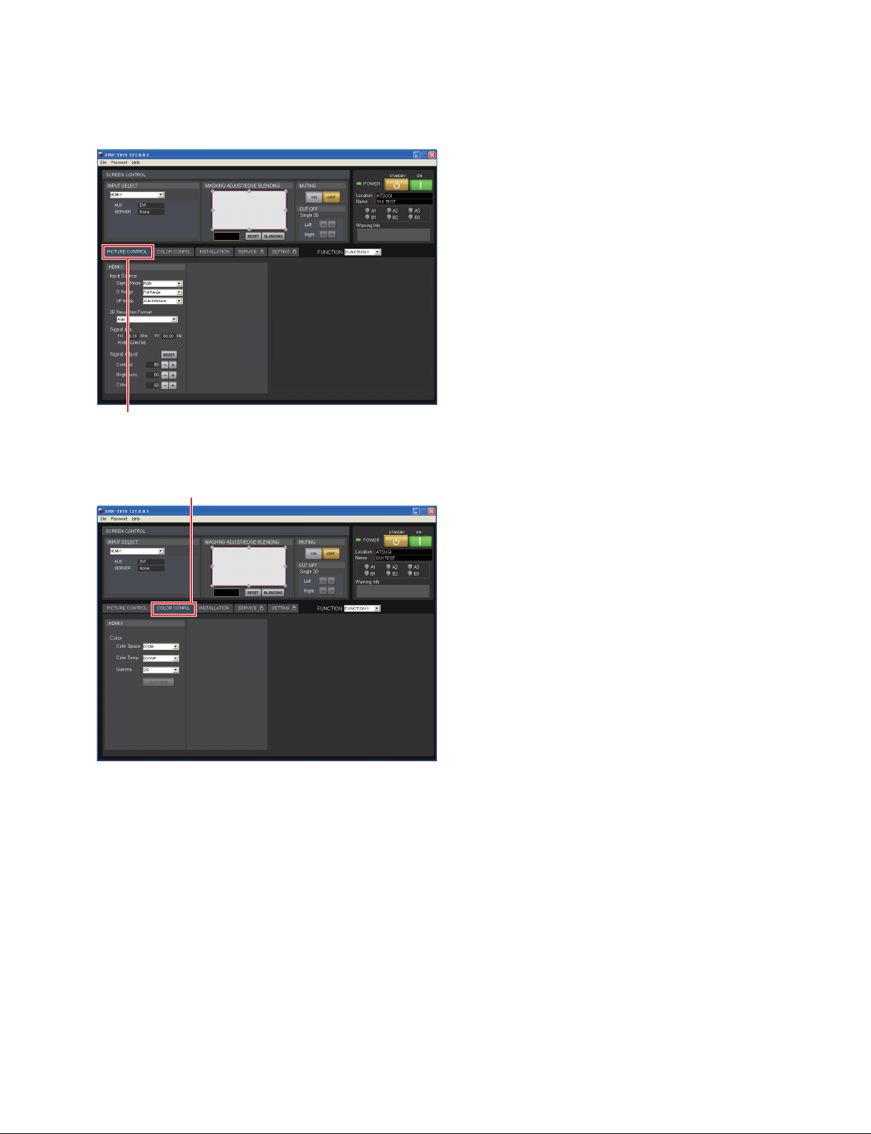
2. [PICTURE CONTROL] tab
Screen example
[PICTURE CONTROL] tab
3. [COLOR CONFIG.] tab
Screen example
[COLOR CONFIG.] tab
SRX-T615
2-5 (E)
Page 30
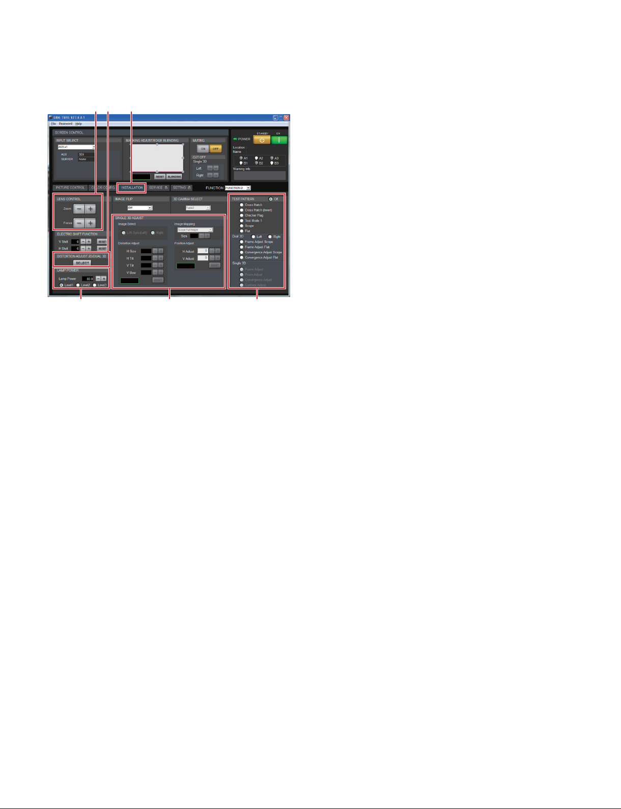
4. [INSTALLATION] tab
Screen
example
1
2 4 3
[INSTALLATION] tab
5
1 [LENS CONTROL]
2 [LAMP POWER]
3 [TEST PATTERN]
4 [SINGLE 3D ADJUST]
5 [DISTORTION ADJUST 2D/DUAL 3D] (MAIN version 3.12.0530 or later)
1 [LENS CONTROL]
Adjusts the image projected on the screen.
. [Zoom] : Adjusts the size of an image. An image is expanded when you click the [+] button. It is
reduced when you click the [_] button.
. [Focus] : Adjusts a focus. A focus is adjusted to the distance place when you click the [+] button. It is
adjusted to the nearby place when you click the [_] button.
2 [LAMP POWER]
. [Lamp Power]: Can adjust the output of a light source lamp bulb in units of 0.1% between
80% and 100%. When a numeric value decreases, the image becomes dark
but the power consumption decreases. In this case, however, the power
consumption decreases. Clicking the [+] button, the numeric value increases. Clicking the [_] button, the numeric value decreases.
. [Level1]/[Level2]/[Level3]: Switches the luminance adjustment filter on the image. Level 3 indicates
the brightest state.
2-6 (E)
SRX-T615
Page 31
3 [TEST PATTERN]
An image can be adjusted by projecting the test pattern, built in this unit, on the screen without inputting
the signal from other equipment.
Each test pattern is as follows:
. “Off”: No test pattern
. “Cross Hatch”
. “Cross Hatch (Invert)”
. “Checker Flag”
. “Test Mode 1”
. “Scope”
. “Flat”
. “Dual 3D”
. “Single 3D”
The test patterns in [Dual 3D] and [Single 3D] are for 3D lens.
4 [SINGLE 3D ADJUST]
This item is for 3D lens.
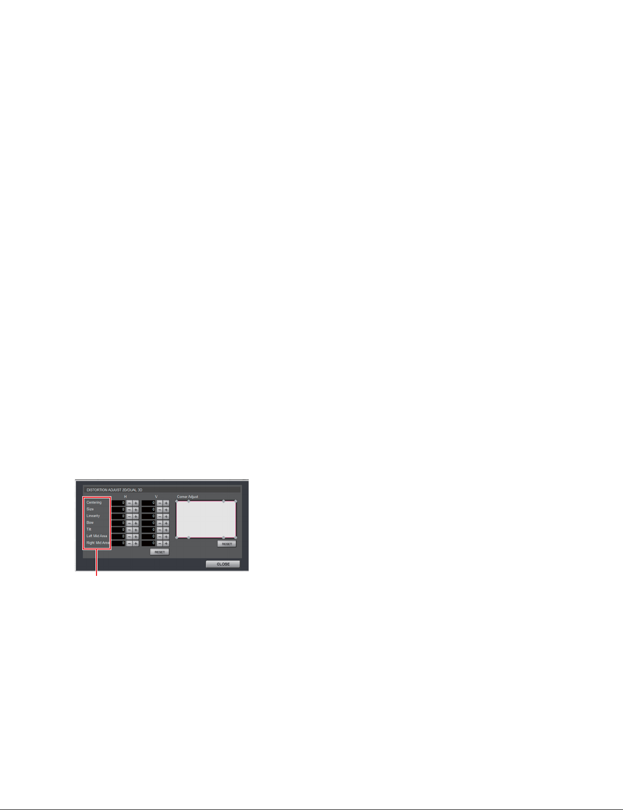
5 [DISTORTION ADJUST 2D/DUAL 3D]
When the MAIN version is earlier than 3.12.0530, this menu (button) is not displayed.
Adjusts the image distortion when the images displayed by the two projectors are overlaid.
When you click the [SELECT] button, the following screen is displayed.
n
When you use the two projectors by placing them next to each other, use the one as the reference projector and adjust the other projector to the reference projector. Do not change the values of the reference
projector except for “Centering”.
Adjust the reference projector only for “Centering” adjustment.
Screen example
Items
Adjust each item by using the [_]/[+] buttons.
SRX-T615
2-7 (E)
Page 32
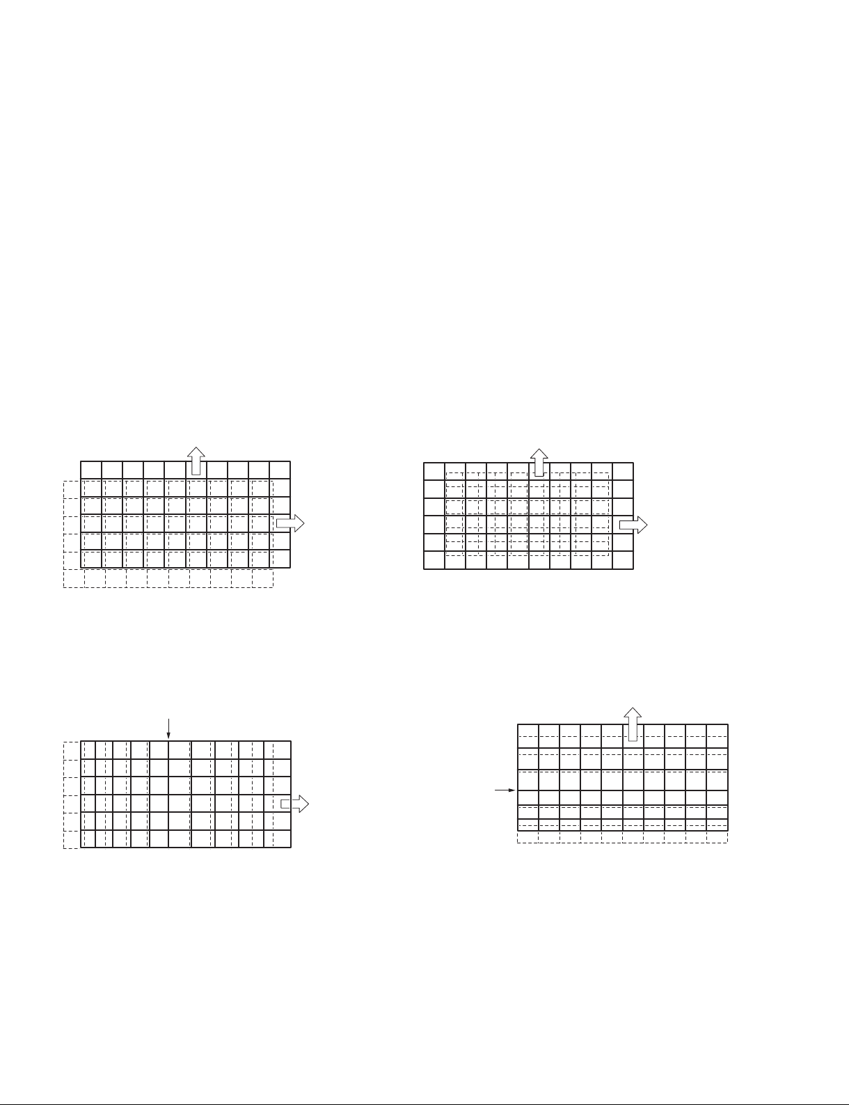
Function and operation of each item
Description of illustration
. The operation method is described by using the [+] button. When the [_] button is clicked, the image
moves in the opposite direction of the [+] button.
. “H” shows the horizontal direction and “V” shows the vertical direction.
. The dashed line shows the original image and the solid line shows the image after it is changed.
. The illustration is shown so that the change of image is easily recognized. Therefore, it is different from
the actual operating range.
Centering
Moves the entire image in parallel.
The image of the reference projector is adjusted. Do not
use “Centering” with the other projector.
H: The image moves in the right direction with the [+]
button.
V: The image moves in the upper direction with the [+]
button.
V:
button
[+]
H:
button
[+]
Linearity (H)
Changes the distance between both ends of the image
without moving the center of H (horizontal).
H: The image expands in the right direction with the [+]
button.
Fix the center.
Size
Changes the entire image size.
H: The right end of the image moves in the right direction
with the [+] button.
(The left end moves in the left direction.)
V: The upper end of the image moves in the upper direc-
tion with the [+] button.
(The lower end moves in the lower direction.)
V:
button
[+]
H:
button
[+]
Linearity (V)
Changes the upper and lower ends of the image without
moving the center of V (vertical).
V: The image expands in the upper direction with the [+]
button.
V:
button
[+]
2-8 (E)
Fix the center.
H:
button
[+]
SRX-T615
Page 33
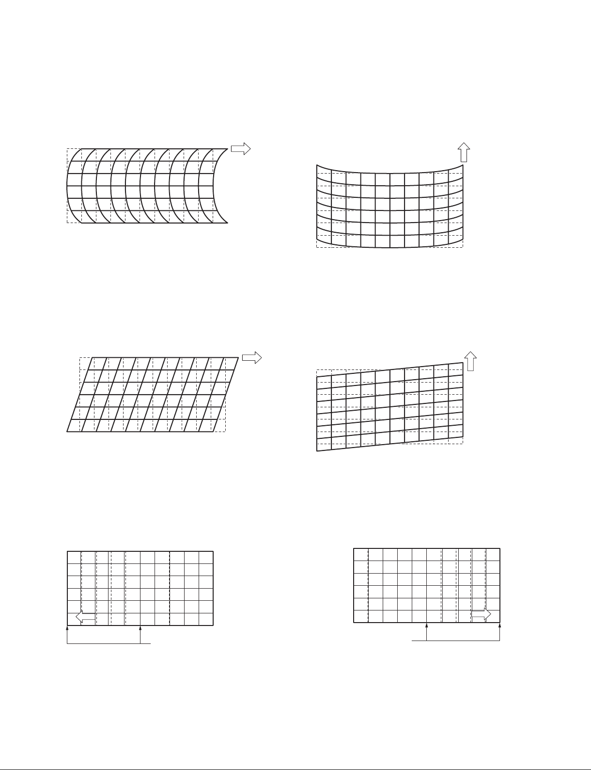
Bow (H)
Changes the right and left ends of the image without moving the center of image.
H: The upper and lower ends of the image moves in the
right direction with the [+] button.
H:
button
[+]
Bow (V)
Changes the upper and lower ends of the image without
moving the center of the image.
V: The right and left ends of the image moves in the upper
direction with the [+] button.
V:
button
[+]
Tilt (H)
Tilts the image without changing the horizontal distance of
vertical lines of the image.
H: The upper end of the image moves in the right direction
with the [+] button.
H:
button
[+]
Left Mid Area (H)
Moves the image in the horizontal direction with the 1/4
portion of the left side image as the center.
The center and left end of the image do not move.
H: The image moves in the left direction with the [+] button.
Tilt (V)
Tilts the image without changing the vertical distance of
horizontal lines of the image.
V: The upper right end of the image moves in the upper
direction with the [+] button.
V:
button
[+]
Right Mid Area (H)
Moves the image in the horizontal direction with the 1/4
portion of the right side image as the center.
The center and right end of the image do not move.
H: The image moves in the right direction with the [+] button.
H:
SRX-T615
[+]
button
Fix the center and left end.
Fix the center and right end.
H:
button
[+]
2-9 (E)
Page 34
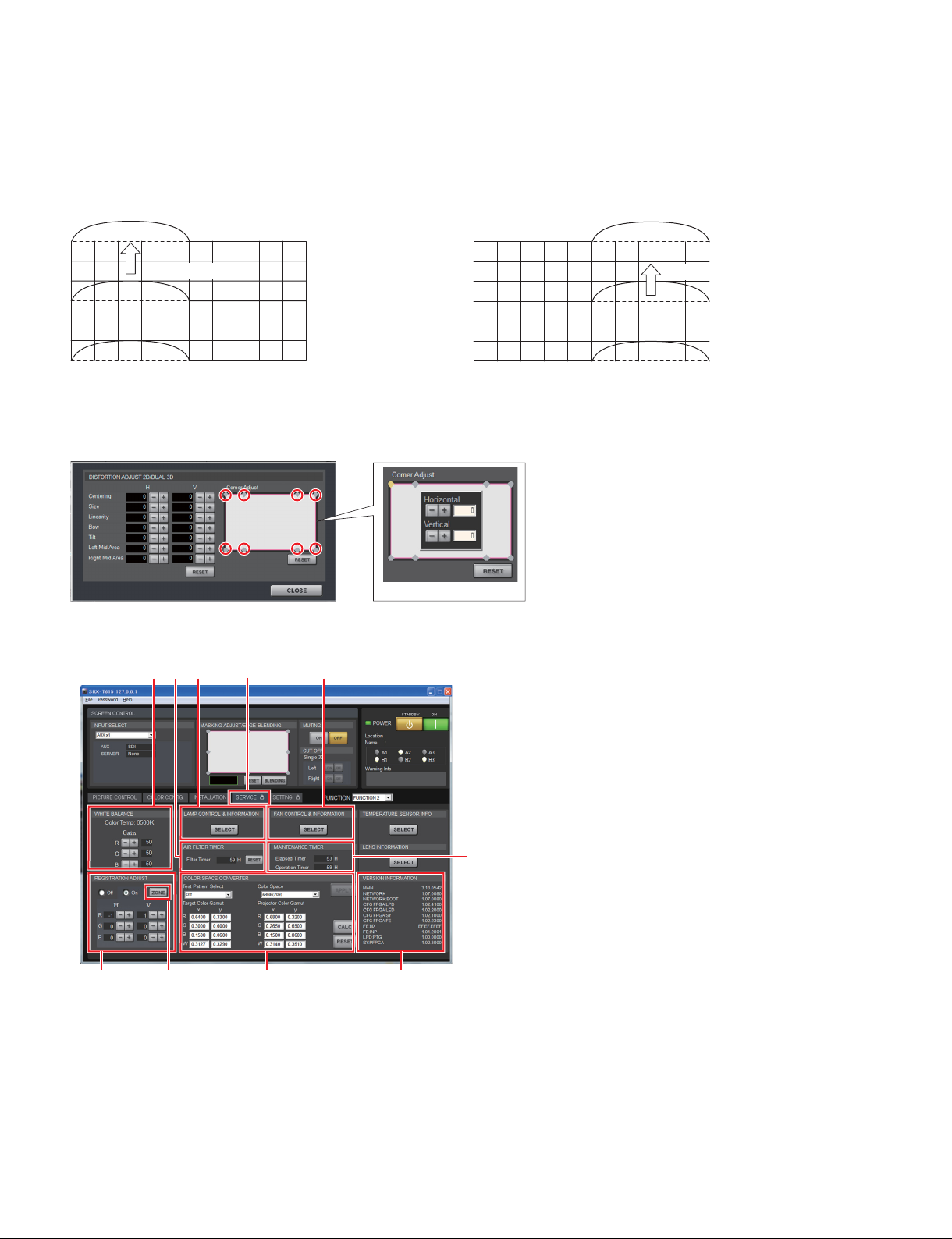
Left Mid Area (V)
Moves the image in the vertical direction with the 1/4
portion of the left side image as the center.
The center and left end of the image do not move.
V: The image moves in the upper direction with the [+] button.
V:
button
[+]
Right Mid Area (V)
Moves the image in the vertical direction with the 1/4
portion of the right side image as the center.
The center and right end of the image do not move.
V: The image moves in the upper direction with the [+] button.
Corner Adjust
Displays the adjustment screen when you double-click the adjustment points A to H.
When you click the [+] button, these points move away from the center.
Screen example
AB CD
EF GH
V:
button
[+]
Adjustment screen
5. [SERVICE] tab
Screen
example
2 7 8
1
9
[SERVICE] tab
3 5
4
1 [WHITE BALANCE]
2 [REGISTRATION ADJUST]
3 [LAMP CONTROL & INFORMATION]
4 [AIR FILTER TIMER]
5 [FAN CONTROL & INFORMATION]
6 [MAINTENANCE TIMER]
7 [COLOR SPACE CONVERTER]
8 [VERSION INFORMATION]
9 [ZONE] button (MAIN version 3.19.0600 or later)
6
2-10 (E)
SRX-T615
Page 35

1 [WHITE BALANCE]
Performs the Gain R/G/B adjustment for setting the color temperature.
It is used to adjust the subtle difference of color among the projectors when more than one projector is
used. When adjusting only one projector, use [Color Space Converter].
The default value is 50. During ordinary adjustment, use at a value of 50 or less. For a value of more than
50, a signal may be deformed.
Adjustment when more than one projector is used
1. Perform the CSC adjustment for all projectors. (Refer to Section 2-6.)
2. Project the 80% white signal.
3. Determine a projector to be used as reference. Adjust the gain value of other projectors so that the
color becomes the same as that of the reference projector.
2 [REGISTRATION ADJUST]
Moves R (red), G (green), and B (blue) in the horizontal and vertical directions up to two pixels, one pixel
at a time so as to adjust registration.
. On: Selects when adjusting.
. Off: Selects when not adjusting.
. H: Pixels move in the horizontal direction.
R: Red pixels horizontally move up to two pixels, one pixel at a time when you click the [+]/[_]
button.
G: Green pixels horizontally move up to two pixels, one pixel at a time when you click the [+]/[_]
button.
B: Blue pixels horizontally move up to two pixels, one pixel at a time when you click the [+]/[_]
button.
. V: Pixels move in the vertical direction.
R: Red pixels vertically move up to two pixels, one pixel at a time when you click the [+]/[_]
button.
G: Green pixels vertically move up to two pixels, one pixel at a time when you click the [+]/[_]
button.
B: Blue pixels vertically move up to two pixels, one pixel at a time when you click the [+]/[_]
button.
3 [LAMP CONTROL & INFORMATION]
Changes the time of the lamp used and the number of lamps.
Lamp information can be exported when you click the [INFO] button in [LAMP] and the [EXPORT]
button in the LAMP IMFORMATION screen.
. [Lamp Number Select]: Select the number of lamps.
. [Change Mode Select]: When “2” or “3” is selected in [Lamp Number Select], the switching mode can
be selected from “Auto” or “Manual”.
In the Auto mode, select the interval time.
In the Manual mode, select the lighting pattern in [Lamp Select].
n
When “Auto” is selected in [Change Mode Select], another lamp automatically
lights in case that a lamp failure occurs. Therefore, the number of lamps is
maintained at all times.
The function does not operate when “6” is selected in [Lamp Number Select]
or when lamp power is defective.
SRX-T615
2-11 (E)
Page 36

4 [AIR FILTER TIMER]
Displays and resets the operation time of air filter.
. [Filter Timer]: Displays the operation time of the air filter on the panel duct.
. [RESET] button: Clicking the button, resets air filter timer.
5 [FAN CONTROL & INFORMATION]
Displays the information on the rotation frequency of a fan used in this unit and sets the cooling method.
The cooling method is set as described below.
During use of a 450 W lamp
. Installation at an altitude of 0 to 500 m: Set to “Mode1”.
. Installation at an altitude of 501 to 1000 m: Set to “Mode2”.
. Installation at an altitude of 1001 to 1500 m: Set to “Mode3”.
t
When installing at an altitude of 1501 m or more, contact your local Sony Sales Office/Service Center.
During use of a 330 W lamp
. Installation at an altitude of 0 to 500 m: Set to “Mode1”.
. Installation at an altitude of 501 to 1000 m: Set to “Mode2”.
. Installation at an altitude of 1001 to 2000 m: Set to “Mode3”.
t
When installing at an altitude of 2001 m or more, contact your local Sony Sales Office/Service Center.
6 [MAINTENANCE TIMER]
[Elapsed Timer]: Displays the lighting time of a lamp.
[Operation Timer]: Displays the operating time including cooling.
7 [COLOR SPACE CONVERTER]
Adjusts the CSC. (Refer to Section 2-6.)
8 [VERSION INFORMATION]
Displays the version of this unit.
9 [ZONE] button
When the MAIN version is earlier than 3.19.0600, this button is not displayed.
Corrects the misregistration by adjusting R (Red), G (Green) and B (Blue) of the image.
(Refer to Section 2-5-1.)
2-12 (E)
SRX-T615
Page 37
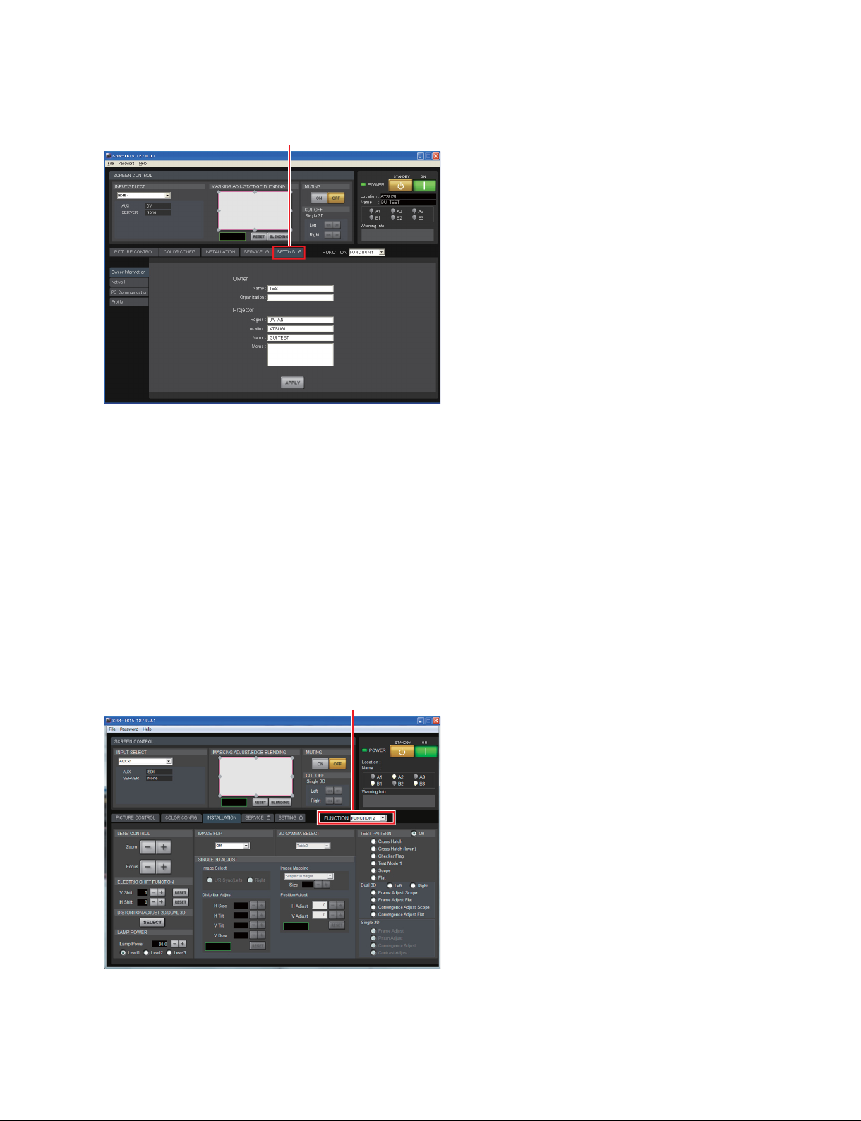
6. [SETTING] tab
Screen example
[SETTING] tab
Sets the various settings of this unit. (Refer to Section 2-2.)
2-1-5. Function Memory
You can register the settings that have been adjusted in the control screens to “FUNCTION 1” to “FUNCTION 8”.
As the default setting, the settings are registered to “FUNCTION 1”. To register the settings to “FUNCTION 2” to “FUNCTION 8”, select one of the “FUNCTION 2” to “FUNCTION 8” from the pull-down
menu, then adjust the items in each screen.
To gain access to the registered setting value, select the desired FUNCTION from the pull-down menu.
n
The system may temporarily enter a muting state (for a maximum of about ten seconds) when the pulldown menu of [FUNCTION] is switched during switching to another FUNCTION setting. After that, the
muting state is switched to the selected setting screen.
Screen example
[FUNCTION]
2-1-6. Log Function
If you select [File] → [Save Log] on the menu bar of the control screen, the communication log between SRX
Controller and this unit (from the startup of SRX Controller to that point of time) can be stored up to 5 MB.
SRX-T615
2-13 (E)
Page 38
2-2. Setting of This Unit
The status of this unit is set.
2-2-1. Operation Method of Setting
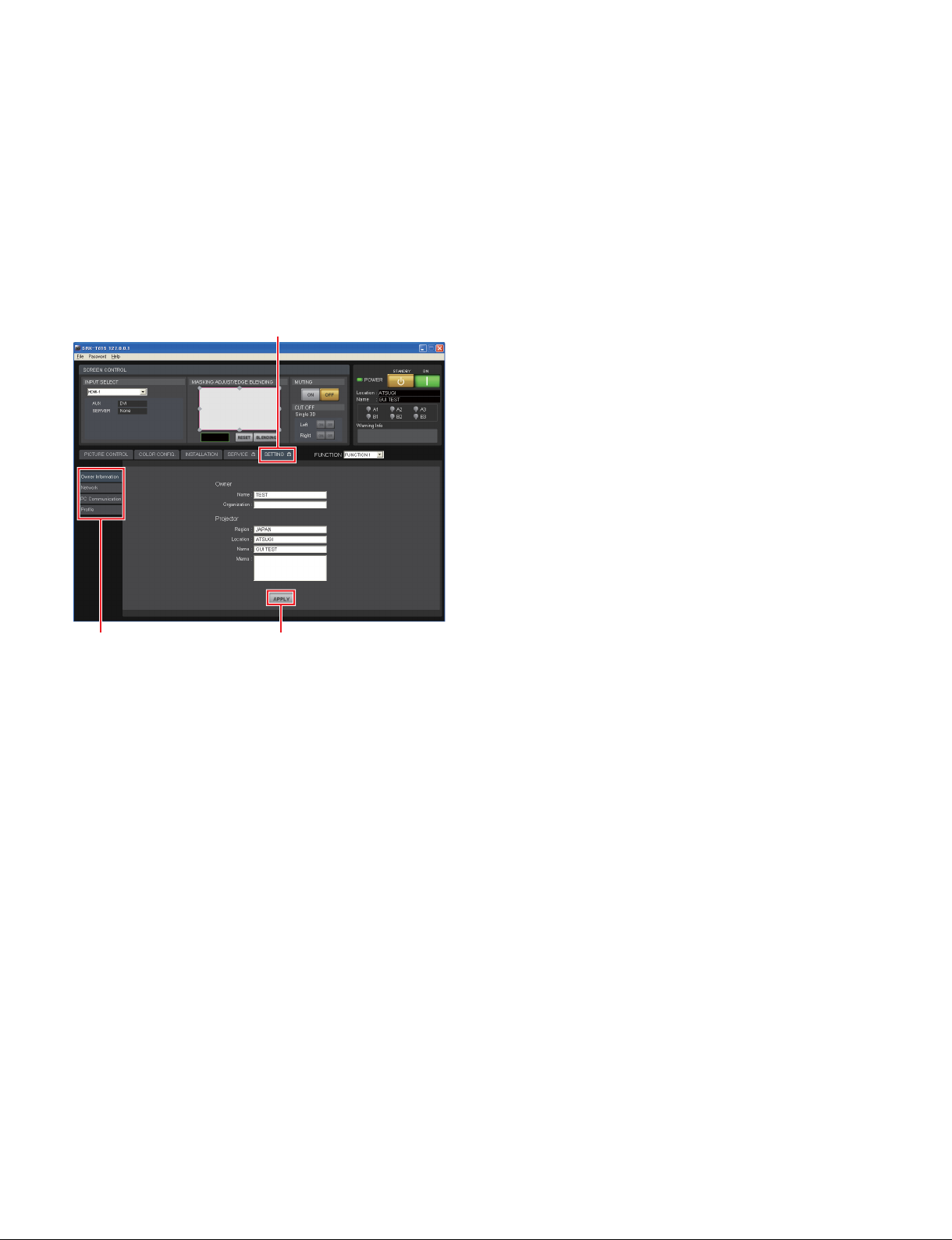
1. Start the SRX Controller, then click the [SETTING] tab. (Refer to Section 2-1-3.)
The [SETTING] screen is displayed.
Screen example
[SETTING] tab
Setting item
[APPLY]
button
2. Click the setting item on the left side of the [SETTING] screen to display the item that you want to
set.
3. After setting the items, click the [APPLY] button.
The setting is registered.
2-14 (E)
SRX-T615
Page 39
2-2-2. Owner Information
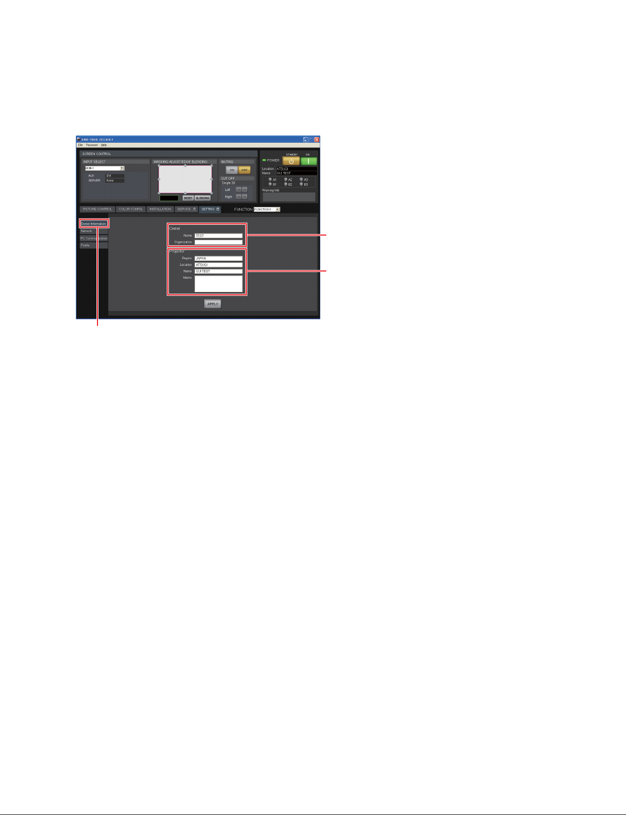
The information on this unit is set. (arbitrarily setting)
Screen example
[Owner Information]
[Owner]
[Name] : Type the name of owner.
[Organization] : Type the name of organization.
[Owner]
[Projector]
[Projector]
[Region] : Type the region that the unit is installed.
[Location] : Type the installation location.
[Name] : Type the arbitrary name.
[Memo] : Type a memo.
SRX-T615
2-15 (E)
Page 40
2-2-3. Network
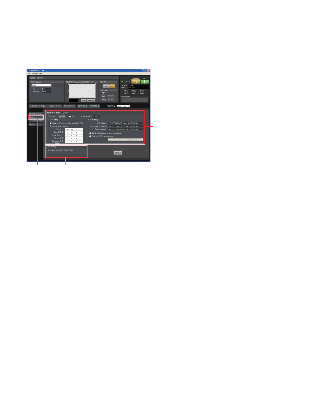
The connection to the network is set.
Screen example
[Network] [LAN Setting]
[Internet Protocol (TCP/IP)]
Select either one of the “IPv4” or “IPv6” in the [Priority].
[Internet Protocol (TCP/IP)]
[IPv4 Setting]
. [Obtain an IP address automatically]: Obtains the IP address automatically from DHCP.
. [Specify an IP address]: Sets the specified IP address.
When “Specify an IP address” is selected, perform the setting in the following boxes.
. [IP Address]: Type the IP address.
. [Subnet Mask]: Type the subnet mask.
. [Default Gateway]: Type the default gateway.
. [Primary DNS]: Type the IP address of primary DNS server.
. [Secondary DNS(Option)]: Type the IP address of secondary DNS server.
[IPv6 Setting]
. [IPv6 Address]: Displays the automatically obtained global address.
. [Link Local IPv6 Address]: Displays the link local address.
. [Default Gateway]: Displays the automatically obtained default gateway.
. [Obtain a DNS server address automatically]: Sets whether automatically obtain a DNS server from
DHCP server.
. [Specify a DNS server address]: Type the IPv6 address of DNS server when DNS server
is not automatically obtained.
[LAN Setting]
[MAC Address] : Display the MAC address.
2-16 (E)
SRX-T615
Page 41
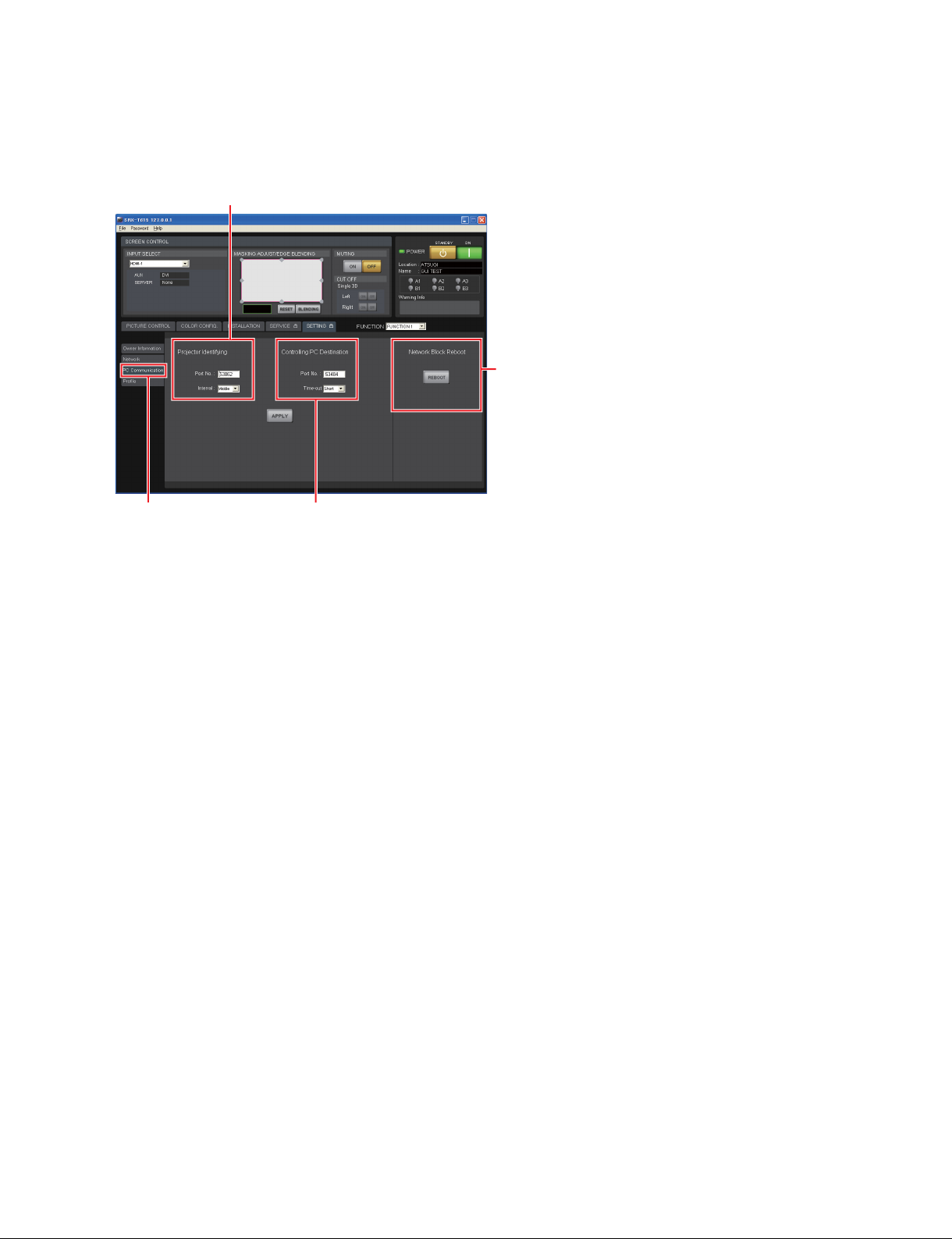
2-2-4. PC Communication
The communication between this unit and PC is set.
Screen example
[Projector Identifying]
[Network Block Reboot]
[PC Communication]
[Controlling PC Destination]
[Projector Identifying]: Sets this unit.
[Port No]: Type the UDP port number.
[Interval]: Select the packet transmission interval.
[Controlling PC Destination]: Sets the PC.
[Port No.]: Type the TCP port number.
[Time-out]: Select the time of the communication time-out.
[Network Block Reboot]
[REBOOT] button: Click this button to reboot the network CPU.
n
After setting PC Communication, a reboot of the network CPU is required.
SRX-T615
2-17 (E)
Page 42
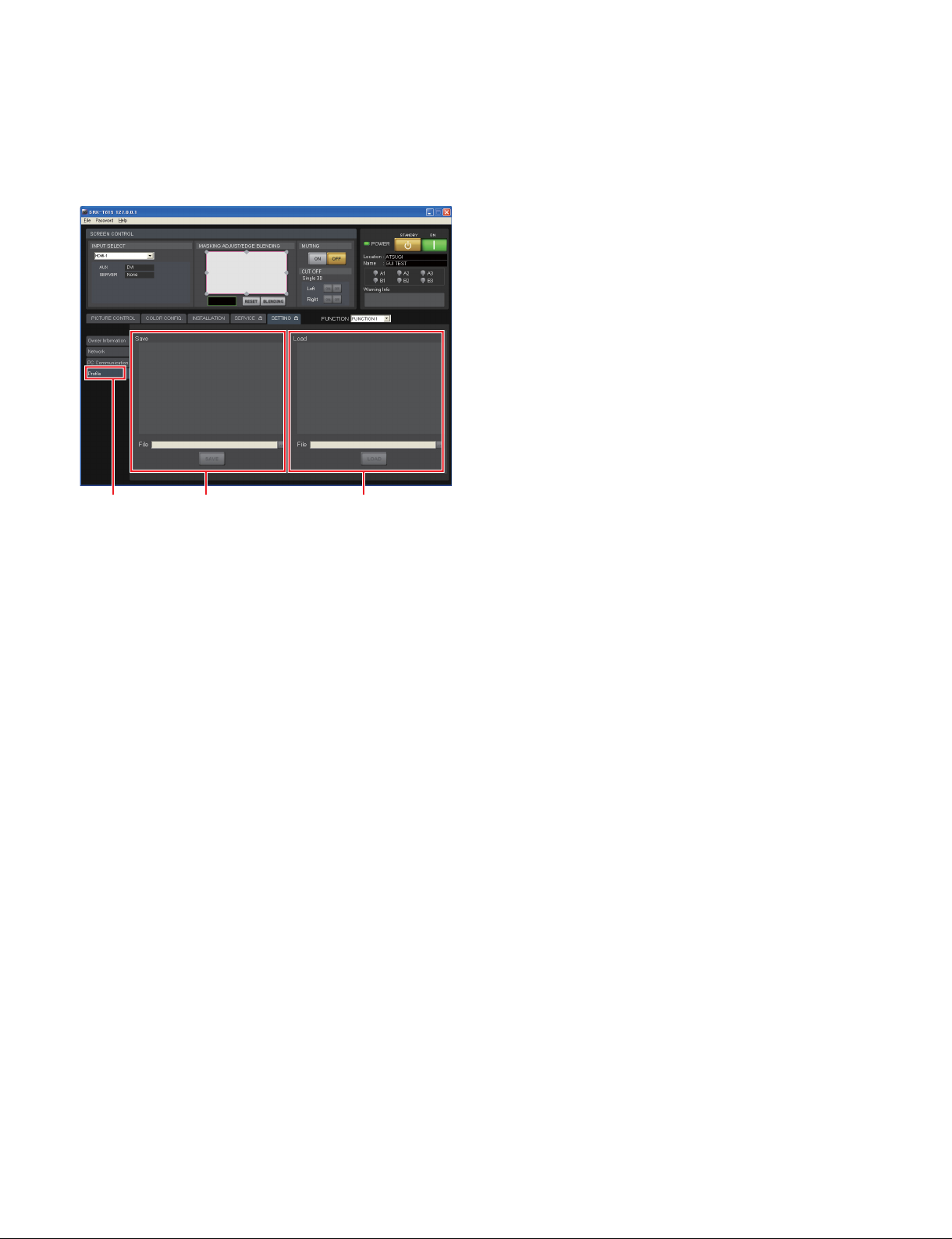
2-2-5. Profile
The setting value of this unit is stored in PC, or the setting value stored in PC is written in this unit.
Screen example
[Profile] [Save] [Load]
[Save]: Place a check mark in the setting value to be stored in PC.
[File]: Edit and select the file name to be stored.
. [...] button: Select the file.
. [SAVE] button: Store the checked setting value in the specified file.
[Load]: Place a check mark in the setting value to be written in this unit from PC.
[File]: Edit and select the file name to be written.
. [...] button: Select the file to be written.
. [LOAD] button: Write the checked setting value in this unit from the specified file.
n
After loading is executed, be sure to restart this unit by turning the power switch on the rear side of this
unit off and on again.
t
In the case that PC and this unit are connected by Ethernet, PC Communication, Network and IPv6 cannot
be set.
2-2-6. Signal Input from Optional Board
In the case of using an optional board, if you change an input signal at the optional board, it sometimes
appears noise on a screen.
It is recommended to perform the masking for approximately 5 seconds in advance.
2-18 (E)
SRX-T615
Page 43
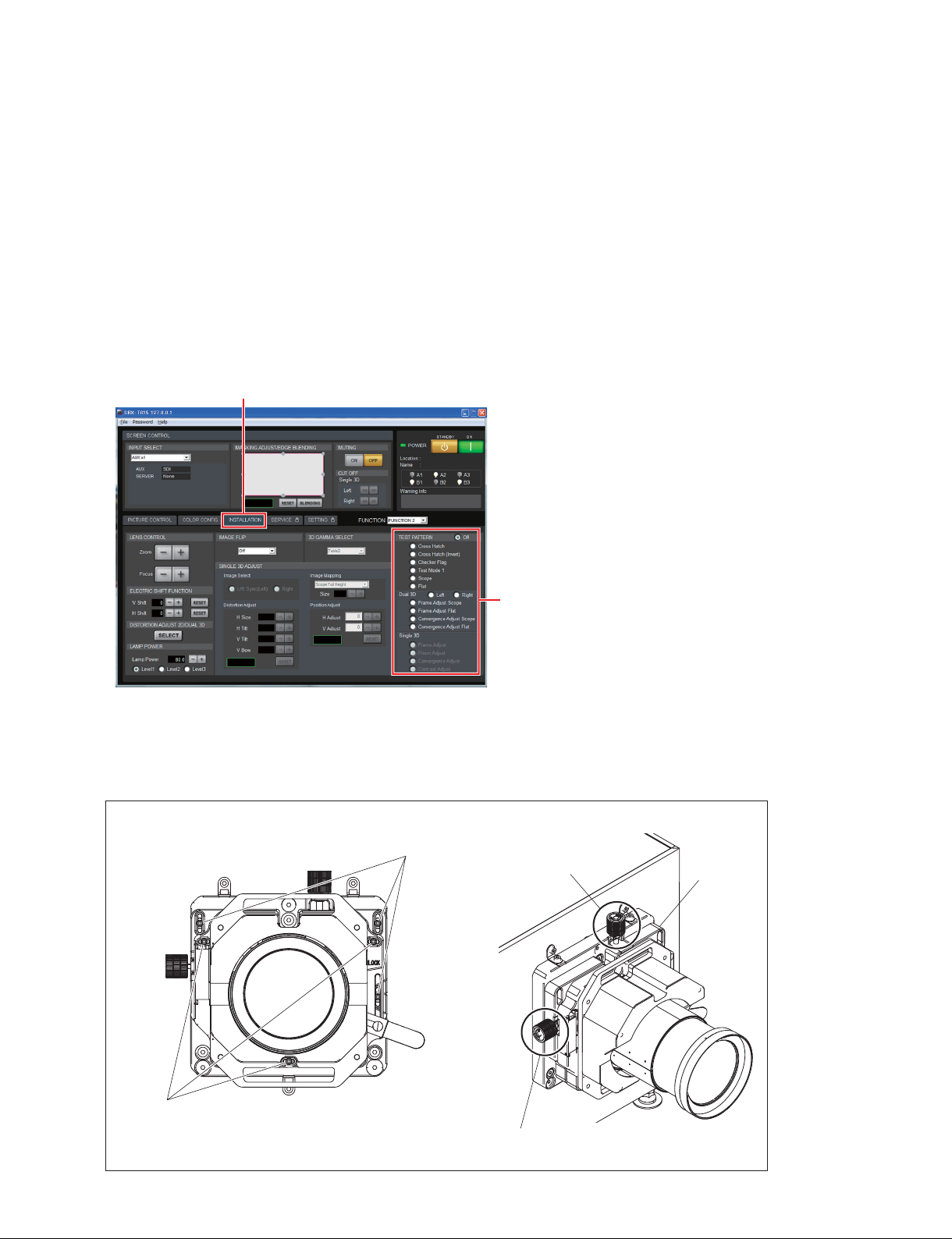
2-3. Lens Adjustment
This adjustment is not required when using this unit by only a 3D lens.
2-3-1. Position Adjustment
Perform the position adjustment using the lens shift block.
1. Start the SRX Controller, then click the [INSTALLATION] tab.
The [INSTALLATION] screen is displayed.
2. Select a test pattern in [TEST PATTERN].
Screen example
[INSTALLATION] tab
[TEST PATTERN]
3. Loosen the three V shift lock screws and three H shift lock screws.
4. Adjust the image position in the vertical direction by rotating the V shift knob.
5. Adjust the image position in the horizontal direction by rotating the H shift knob.
6. Tighten the three V shift lock screws and three H shift lock screws.
V shift lock screws
(3 pcs)
V shift knob
Lens shift
block
H shift lock screws
(3 pcs)
SRX-T615
H shift knob
2-19 (E)
Page 44
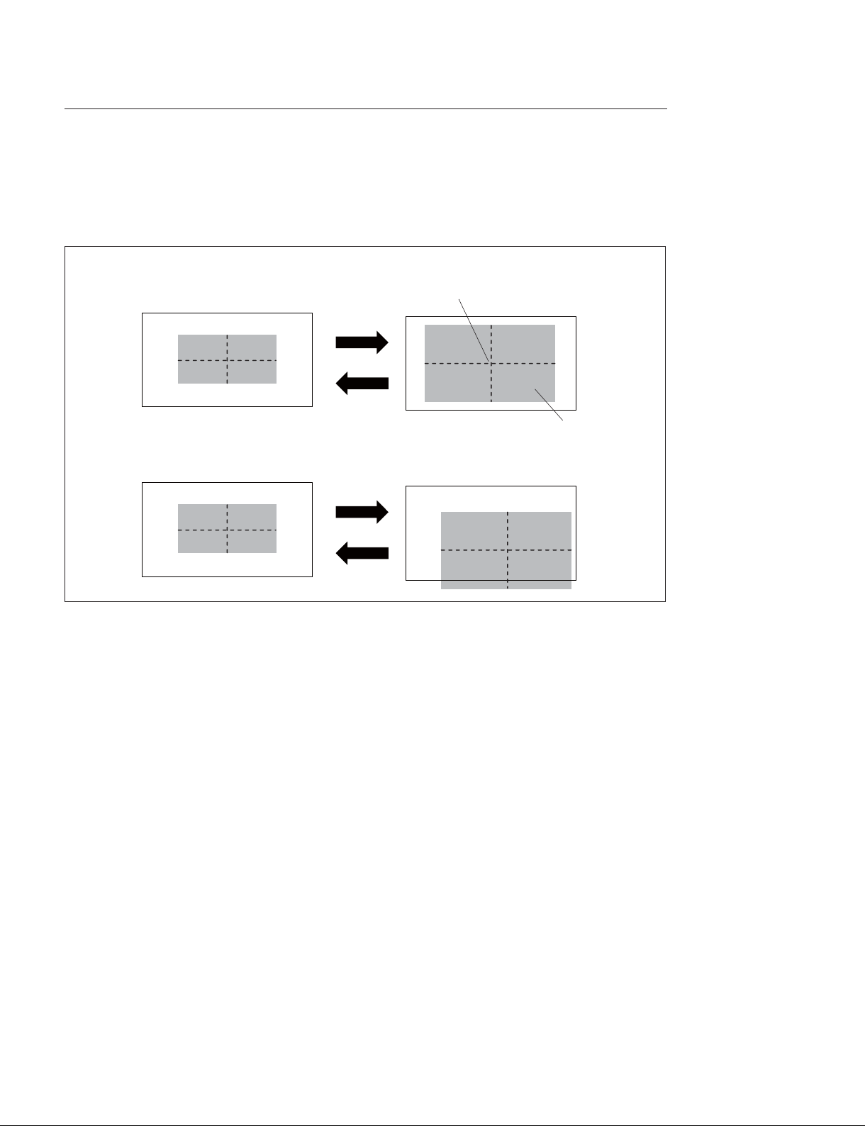
Precaution for using the V shift and H shift with the lens shift block
When using the V shift and H shift with the lens shift block, be careful with the following.
The center position of the image is changed when zooming.
When the V shift or H shift of the lens shift block is used, the center position of image is deviated when
zooming.
When the V shift or H shift of the lens shift block is not used, the center position of image is not changed.
Center position of image
Image
When the V shift or H shift of the lens shift block is used, the center position of image is changed.
The zoom ratio varies depending on the field angle (flat, scope, 16:9) of contents when zooming according to the screen size. Therefore, it is required to correct the center position of image. The adjustment of
the image center position is performed using the SRX Controller (Refer to Section 2-3-2.). Since the
adjustable tolerance in the vertical and horizontal directions varies depending on the field angle of contents, it needs to be corrected in the following procedure.
. When you want to perform the V shift, adjust the image position with flat (vertically longest field
angle), then correct the image center position with other field angles (scope, HD).
. When you want to perform the H shift, adjust the image position with scope (horizontally longest field
angle), then correct the image center position with other field angles (flat, HD).
2-20 (E)
SRX-T615
Page 45
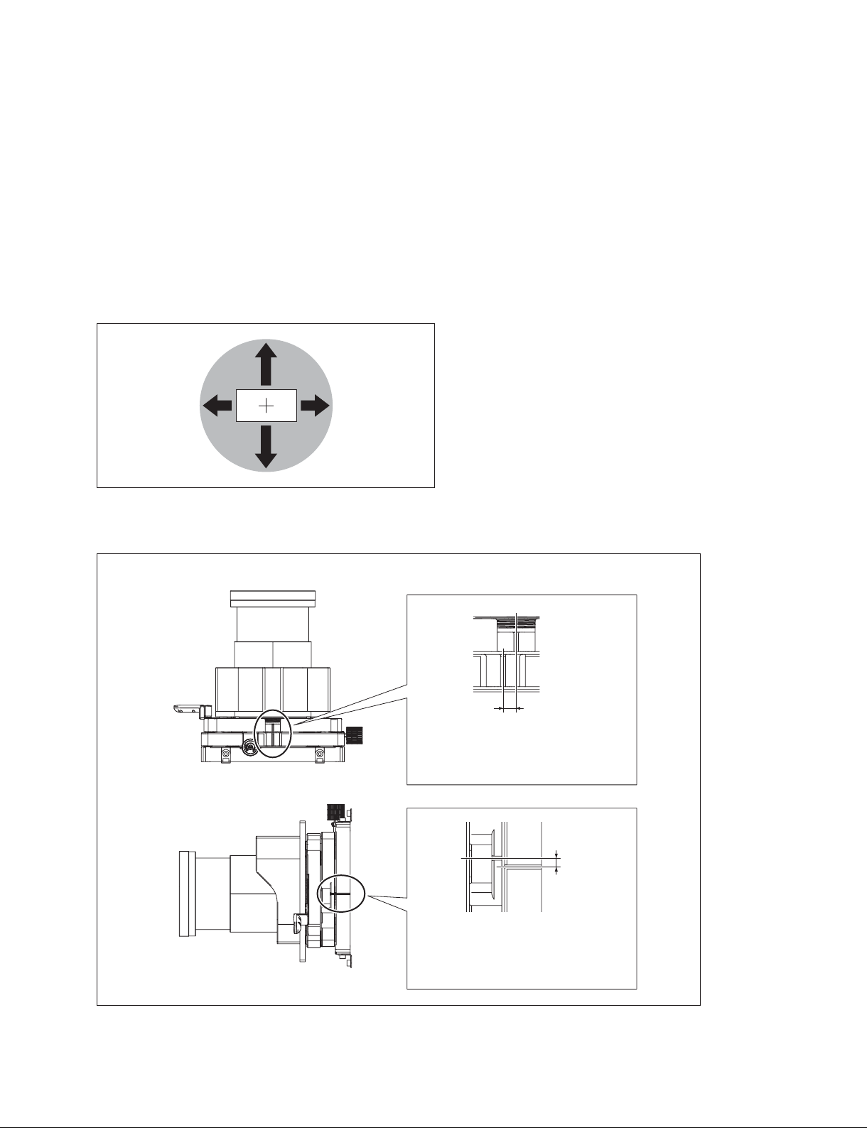
About the maximum adjustment range
The V shift and H shift with the lens shift block is realized by changing the area used in the round-shaped
lens. Therefore, the maximum adjustment range becomes as shown in the following illustration (image).
On the other hand, it is mechanically possible to adjust the V shift and H shift over the maximum adjustment range.
The lens shift amount (%) is indicated by the proportion assuming that the “height” or “width” of the
projected image is 100%. If the V shift or H shift is moved over the maximum adjustment range, the
image degradation or vignetting (lack of image) in the outer edge portion may occur, or the image center
position may not be adjusted when zooming. There is no problem to use them over the maximum adjustment range if you understand these conditions. However, it is recommended to use them within the maximum adjustment range for ordinary purposes.
35%
7% 7%
35%
Method for checking if the V shift and H shift are within the maximum adjustment range
H shift
When completely aligned:
0 % (no shift)
When deviated by about 2 mm:
7% (Maximum adjustment range)
V shift
When completely aligned:
0 % (no shift)
When deviated by about 5.5 mm:
35% (Maximum adjustment range)
SRX-T615
2-21 (E)
Page 46
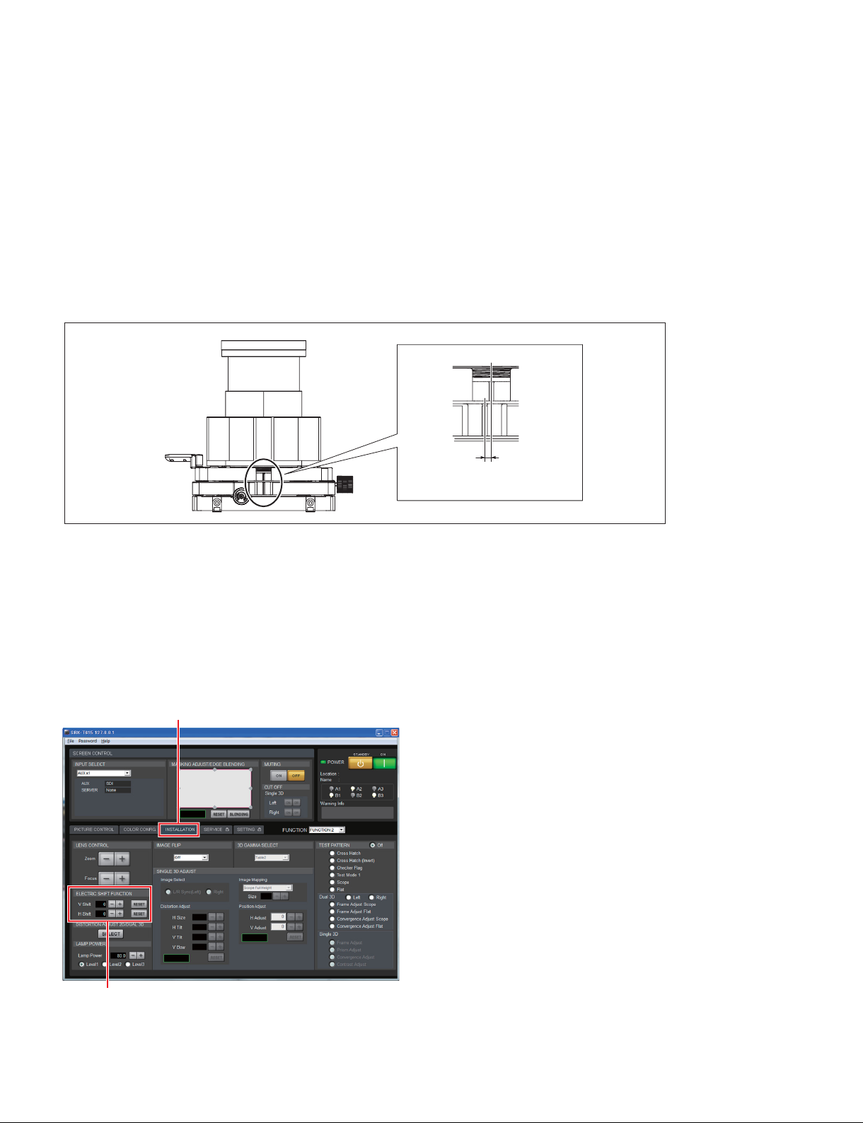
In the 2D lens and 3D lens, the image position moves in the reverse direction when performing the H shift.
When attaching the 3D lens after performing the H shift with the 2D lens, the image moves to the opposite
side due to the mechanism of this unit. Because of this, when you want to project the image to the same position using the 3D lens after using the H shift with the 2D lens, it is required to return the image to the position using the SRX Controller (Refer to Section 2-3-2.). Since the maximum value of H shift that can be
performed by the SRX Controller when using the 3D lens is ?7 %, the H shift with the lens shift block needs
to be up to ?3.5 % taking into consideration the amount of H shift to be returned that was used by the 2D
lens.
Method for checking if the H shift is ?3.5 % or less
H shift
When deviated by about 1 mm:
3.5%
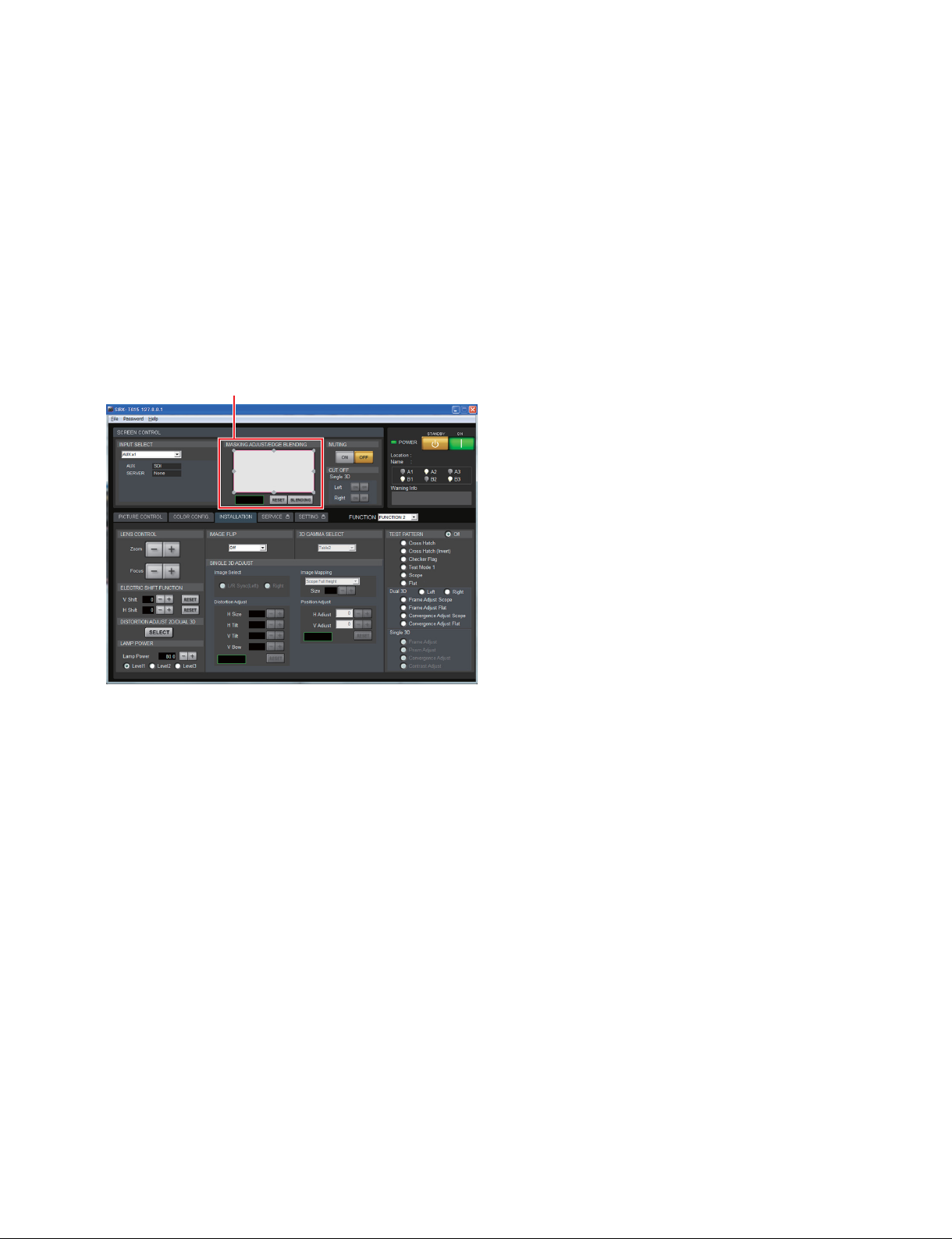
2-3-2. Position Adjustment (Electric Shift Using SRX Controller)
This adjustment is performed for adjusting the center position of image when zooming and so on in the
case of using the V shift and H shift with the lens shift block.
1. Click the [INSTALLATION] tab.
2. Adjust the [V Shift] or [H Shift] using [_] and [+] buttons in the [ELECTRIC SHIFT FUNCTION].
Screen example
[INSTALLATION] tab
[ELECTRIC SHIFT FUNCTION]
2-22 (E)
SRX-T615
Page 47
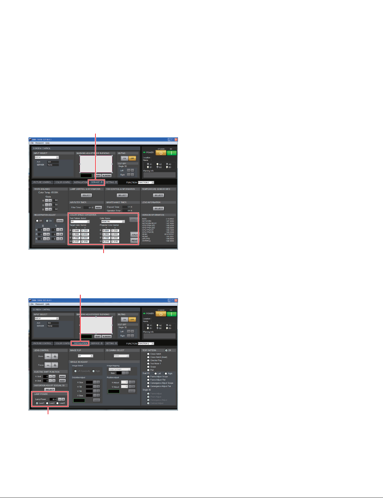
2-3-3. Position Adjustment (Adjusting the Projector Tilt and Direction)
In the case that the V shift amount is insufficient, adjust the length of foot in the rear portion of this unit to
tilt this unit. (Refer to Section 1-7.)
In the case that the H shift amount is insufficient, change the projector installation position in order to
project the image obliquely.
Perform the mask processing because a keystone occurs when this unit is tilted.
Mask processing
1. Double-click the adjustment point in [MASKING ADJUST] of the [MASKING ADJUST/EDGE
BLENDING].
The adjustment screen is displayed.
Screen example
[MASKING ADJUST/EDGE BLENDING]
2. Adjust the masking amount.
Click the adjustment point and adjust the horizontal and vertical directions using [_] and [+] buttons
or by direct entry.
. [+] : Setting value is increased.
. [_] : Setting value is decreased.
Click [Reset] to return to the original masking amount.
SRX-T615
2-23 (E)
Page 48
2-3-4. Brightness Adjustment
n
When the CSC adjustment is performed, the brightness changes slightly. After performing the CSC adjustment, adjust the brightness again.
1. Start the SRX Controller, then click the [SERVICE] tab. (Refer to Section 2-1-3.)
The [SERVICE] screen is displayed.
2. Select the “Gray-10” in [Test Pattern Select] of the [COLOR SPACE CONVERTER].
Screen example
[SERVICE] tab
[COLOR SPACE CONVERTER]
3. Click the [INSTALLATION] tab.
Screen example
[LAMP POWER]
[INSTALLATION] tab
4. Select an appropriate luminance level from the three levels in the [LAMP POWER].
t Level 3 is the brightest level.
5. Perform the fine adjustment using [+] and [_] buttons.
2-24 (E)
SRX-T615
Page 49
2-4. Image Adjustment (3D Lens)
The optical axis adjustment, zoom adjustment, focus adjustment, position adjustment, brightness adjustment and registration and calling of adjustment/setting data (FUNCTION MEMORY function) are described here.
Each adjustment is performed in a 3D mode. Therefore, install the 3D lens before adjustment when using
2D and 3D lenses jointly.
Perform gamma and uniformity adjustments using a Projector Color Adjustment Tool and 2D lens before
image adjustment when using this unit by only a 3D lens.
This adjustment is not required when using this unit by only a 2D lens.
2-4-1. Optical Axis Adjustment
The optical axis in the 3D lens is adjusted so that the image for the left eye is projected from the lower
lens and the image for the right eye is projected from the upper lens.
1. Start the SRX Controller.
2. Select “Single 3D HDMI-1(L/R)”, “Single 3D HDMI-2(L/R)”, or “Single 3D HDMI-1(L)/2(R)” in
[INPUT SELECT].
The current state enters a 3D mode.
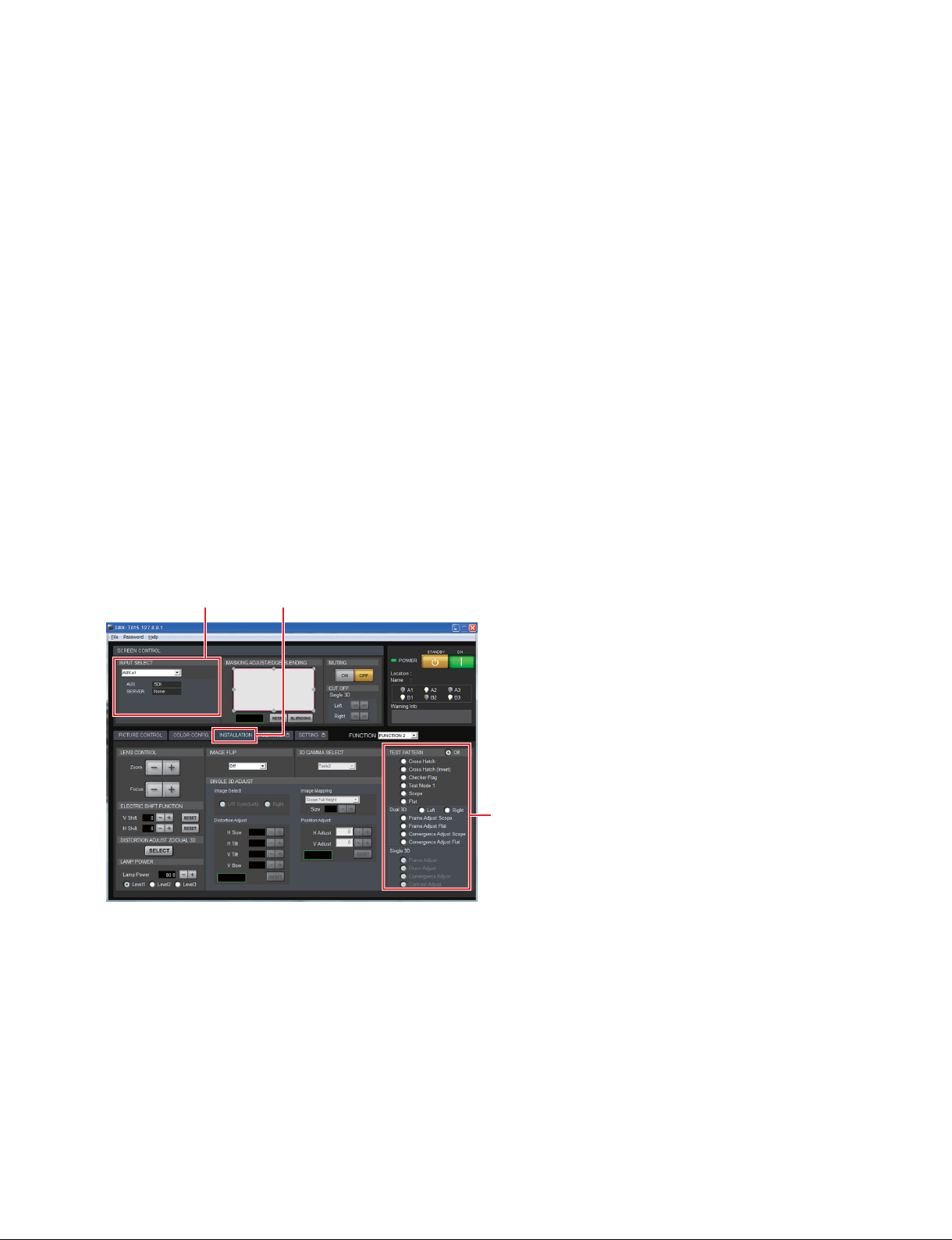
3. Click the [INSTALLATION] tab.
[INPUT SELECT]
Screen example
[INSTALLATION] tab
[TEST PATTERN]
4. Click the “Frame Adjust” radio button in [Single 3D] of [TEST PATTERN].
A test signal is displayed.
SRX-T615
2-25 (E)
Page 50
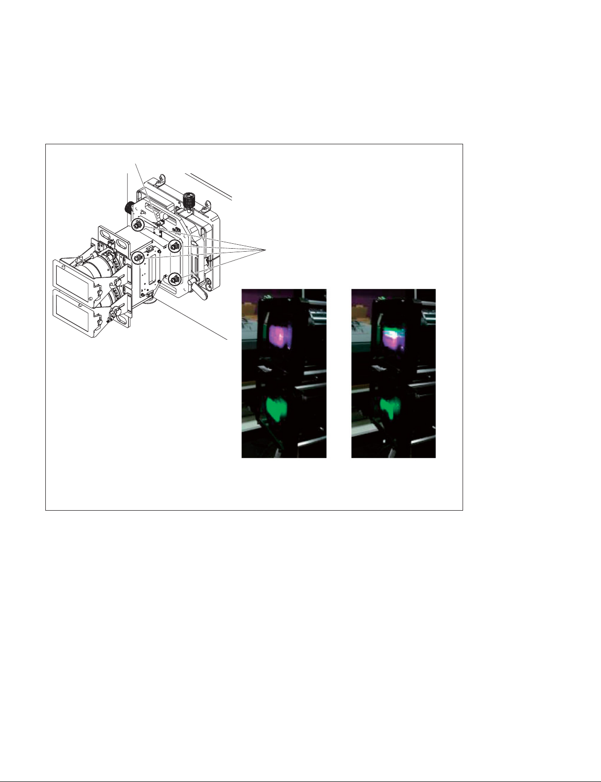
5. Loosen the four optical axis adjustment lock screws by two turns or more.
6. Adjust so that the image for the left eye (green image) is projected from the lower lens and the image
for the right eye (magenta image) is projected from the upper lens by rotating the optical axis adjustment screw.
7. Tighten the four optical axis adjustment lock screws. (Tightening torque: 2.0 N.m)
Optical axis adjustment screw
Optical axis adjustment
lock screws (4 pcs)
OK NG
2-26 (E)
n
The green light beam is
output from the upper lens.
SRX-T615
Page 51
2-4-2. 3D Lens Filter Adjustment (In the Case of LKRA-005)
n
In the LKRA-005 Installation Manual, the procedure for installing LKRA-005 in SRX-R320S is described. When installing LKRA-005 in this unit, follow the procedure in this manual.
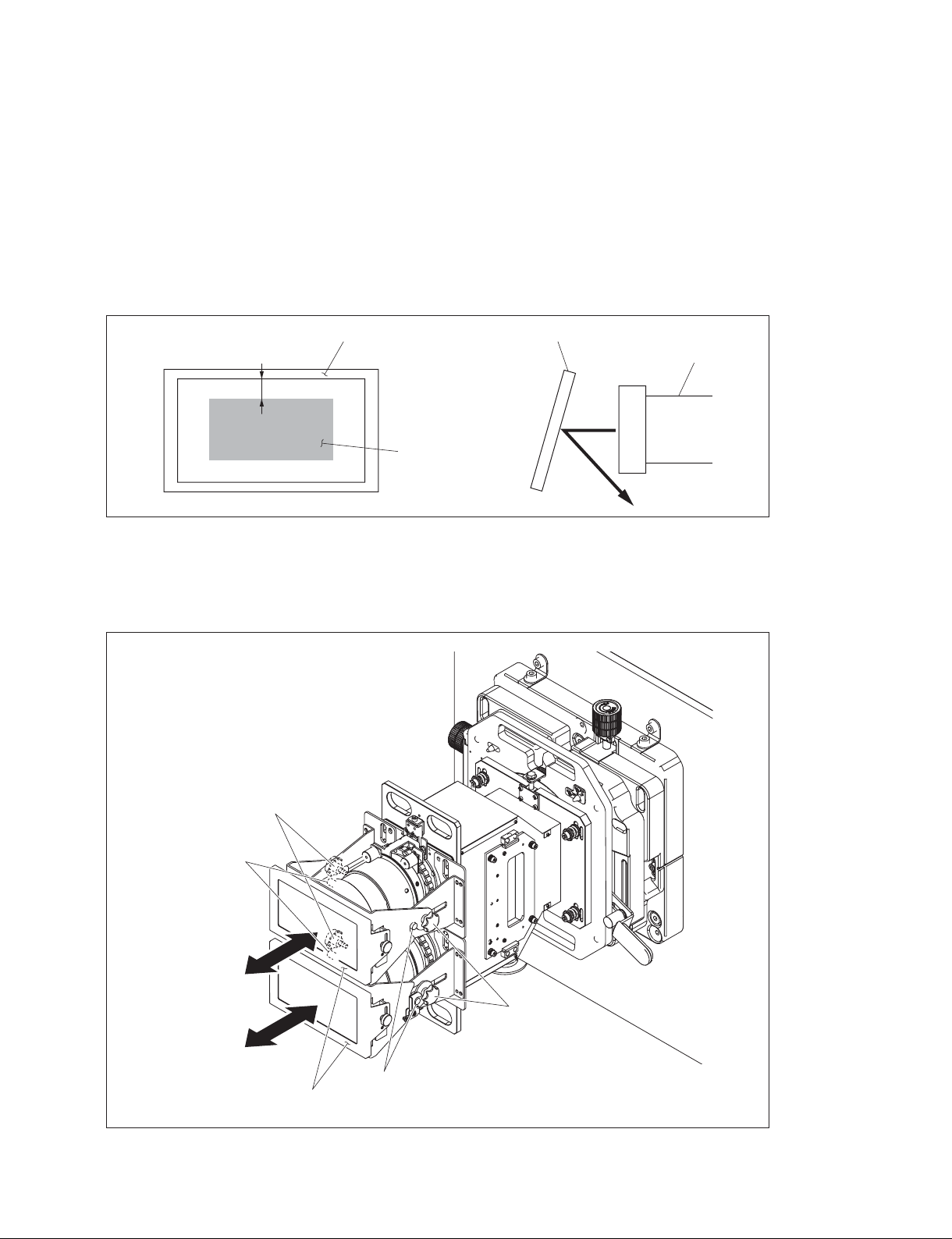
Adjust the position (depth and vertical directions) of the 3D lens filter so that the image is projected inside
the frame by about 1 cm. Also, adjust the tilt of 3D lens filter so that the light reflected by the 3D lens
filter does not return to the lens.
Frame
1 cm
Image
3D lens filter position (depth direction) adjustment
1. Loosen the knobs and position pins.
2. Move the 3D lens filters in the depth direction.
3. Tighten the knobs and position pins.
3D lens filter
Lens
SRX-T615
Knobs
Position pins
Knobs
Position pins
3D lens filters
2-27 (E)
Page 52
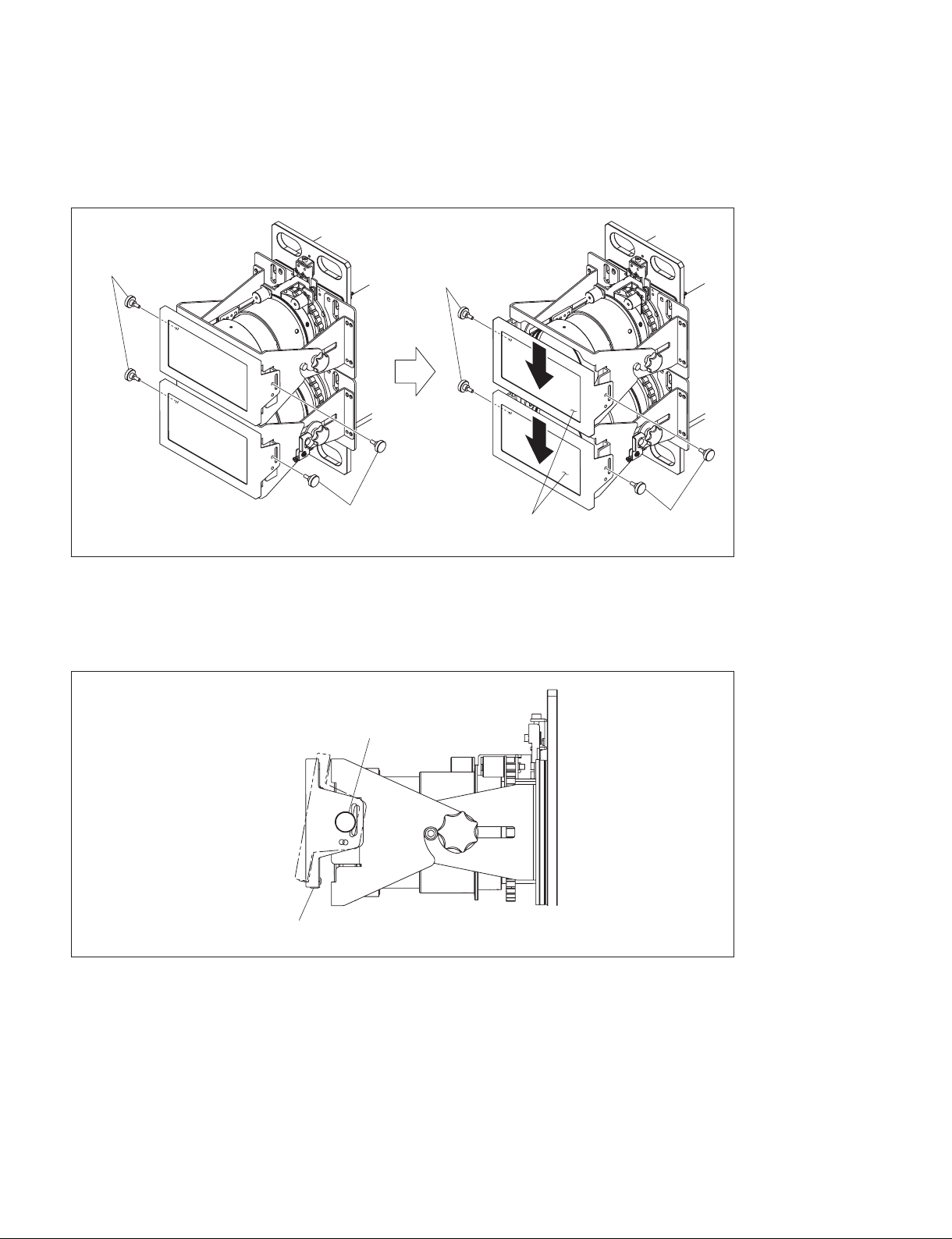
3D lens filter position (vertical direction) adjustment
1. Remove the four adjustment screws.
2. Move the 3D lens filters in the vertical direction by changing the attachment position of the adjustment screws removed in step 1.
Adjustment
screws
3D lens filter tilt adjustment
1. Loosen the two adjustment screws.
2. Tilt the 3D lens filter.
3. Tighten the adjustment screws.
Adjustment
screws
Adjustment
screws
3D lens filters
Adjustment
screws
Adjustment screw
(this screw is also attached on the other side.)
3D lens filter
2-28 (E)
SRX-T615
Page 53
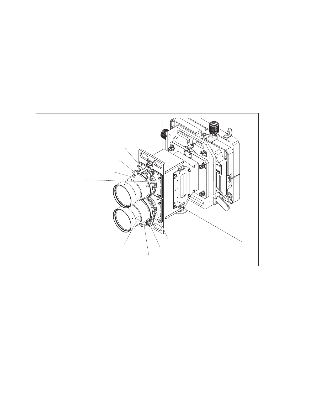
2-4-3. Zoom/Focus Adjustment
The image for the right eye and the image for the left eye are adjusted separately.
The adjustment procedure is the same.
1. Project the test pattern (“Frame Adjust”). (Refer to steps 1 to 4 in Section 2-4-1.)
2. Loosen the zoom lock screws and focus lock screws.
3. Adjust the image size by rotating the zoom rings.
4. Adjust the image focus by rotating the focus rings.
5. Tighten the zoom lock screws and focus lock screws.
Zoom lock screw (image for right eye)
Focus lock screw (image for right eye)
Focus ring (image for right eye)
Zoom ring
(image for right eye)
Zoom ring (image for left eye)
Zoom lock screw (image for left eye)
Focus ring (image for left eye)
Focus lock screw (image for left eye)
n
The 3D lens filters are not shown in the illustration for the sake of clarity.
SRX-T615
2-29 (E)
Page 54
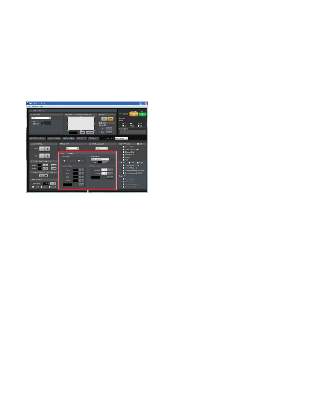
2-4-4. Position Adjustment (Adjust Image Using SRX Controller)
The position adjustment of 3D lens in the horizontal direction is performed using the SRX Controller.
Although it can be performed using the H shift of lens shift block, the images projected by the 2D lens
and 3D lens cannot be adjusted to the same position because the image moves in the reverse direction due
to the mechanism of this unit.
1. Project a test pattern (“Frame Adjust”). (Refer to steps 1 to 4 in Section 2-4-1.)
Screen example
[SINGLE 3D ADJUST]
2. Click the “L/R Sync (Left)” radio button in [Image Select] of [SINGLE 3D ADJUST].
3. Adjust the image position in the horizontal direction in [H Adjust] of [Position Adjust].
2-4-5. Position Adjustment (Adjusting the Projector Tilt and Direction)
In the case that the V shift amount is insufficient, adjust the length of foot in the rear portion of this unit to
tilt the projector. (Refer to Section 1-7.) In the case that the H shift amount is insufficient, change this unit
installation position in order to project the image obliquely.
Perform the mask processing because a keystone occurs when this unit is tilted.
2-30 (E)
SRX-T615
Page 55
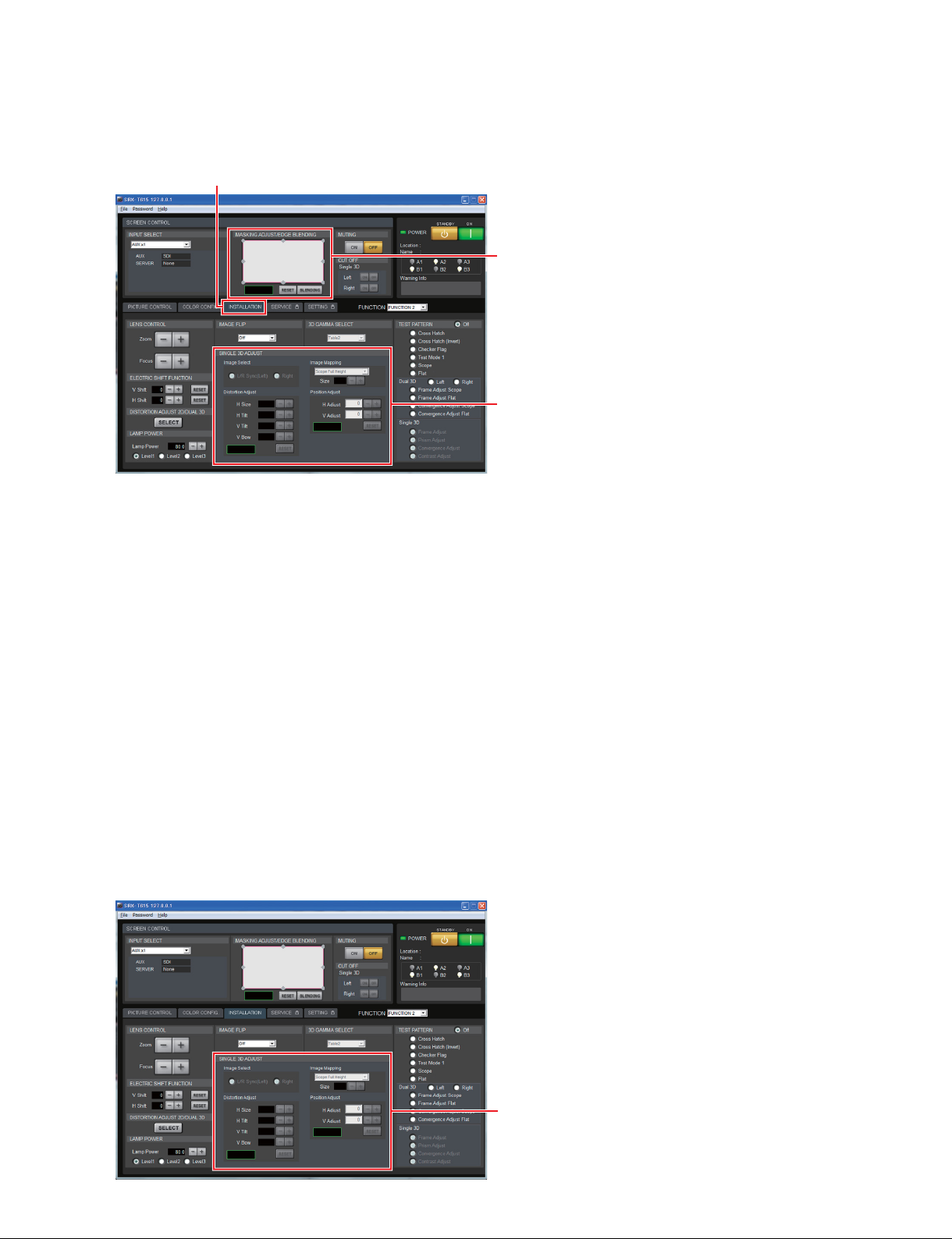
Mask processing
1. Open an [INSTALLATION] screen. (Refer to steps 1 to 3 in Section 2-4-1.)
Screen example
[INSTALLATION] tab
MASKING ADJUST/EDGE BLENDING
[
[SINGLE 3D ADJUST]
]
2. Click the “L/R Sync (Left)” radio button in [Image Select] of [SINGLE 3D ADJUST].
3. Double-click the adjustment point of the [MASKING ADJUST/EDGE BLENDING].
The adjustment screen is displayed.
4. Adjust the masking amount.
Click the adjustment point and adjust the horizontal and vertical directions using [+] and [_] buttons
or by direct entry.
. [+] : Setting value is increased.
. [_] : Setting value is decreased.
Click [Reset] to return to the original masking amount.
2-4-6.
Alignment of the Horizontal Position of Image for Right Eye and Image for Left Eye
1. Project a test pattern (“Frame Adjust”). (Refer to steps 1 to 4 in Section 2-4-1.)
2. Click the “Right” radio button in [Image Select] of [SINGLE 3D ADJUST].
3. Adjust the position of the image for the right eye in the horizontal direction in the [H Adjust] of the
[Position Adjust].
Screen example
[SINGLE 3D ADJUST]
SRX-T615
2-31 (E)
Page 56
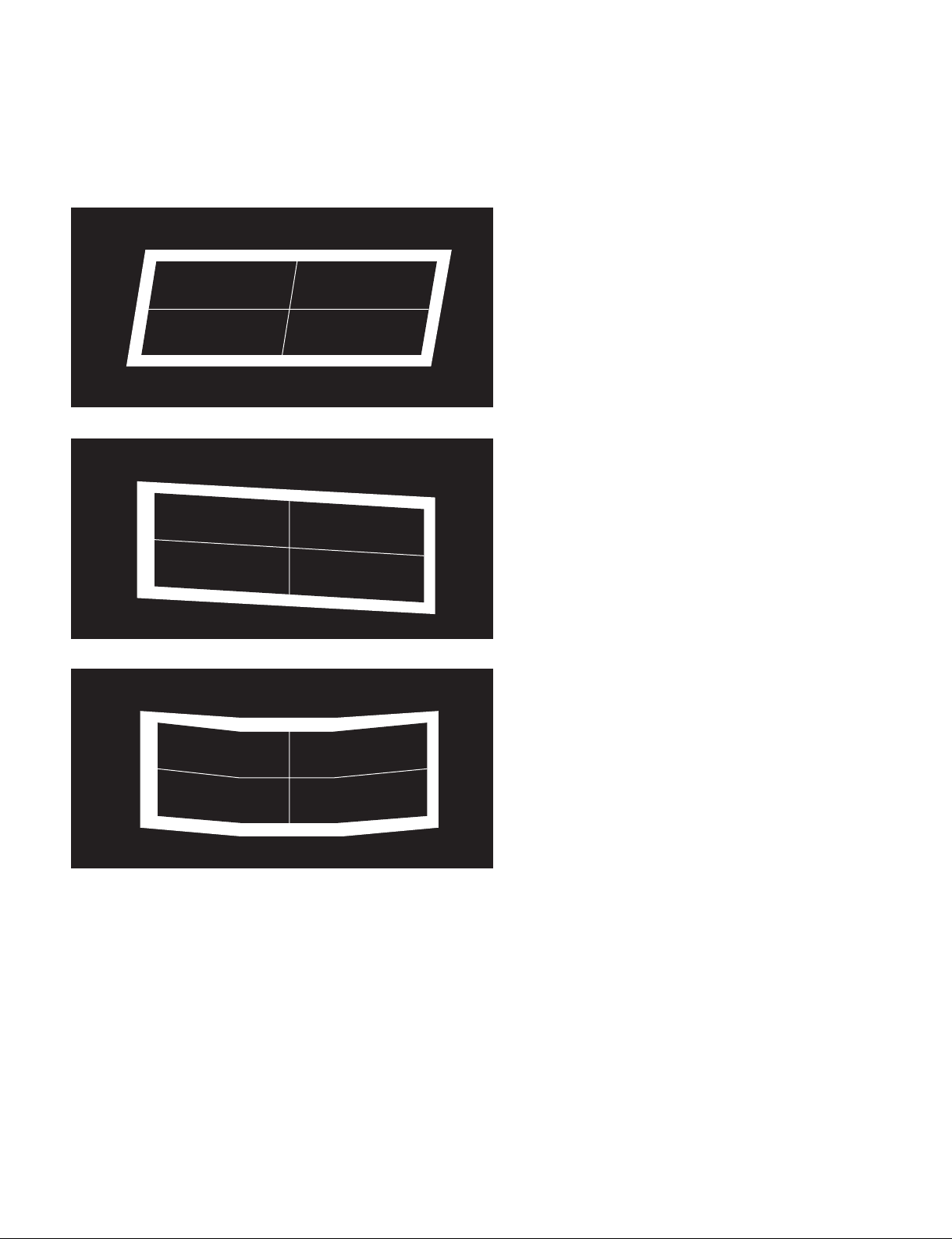
t
Also, the image size in the horizontal direction (H size), image tilt in the horizontal direction (H Tilt), image
tilt in the vertical direction (V Tilt) and the image shape in the vertical direction (V Bow) can be adjusted
In the case of increasing H Tilt (+)
L R
In the case of increasing V Tilt (+)
L R
.
In the case of increasing V Bow (+)
L R
2-32 (E)
SRX-T615
Page 57
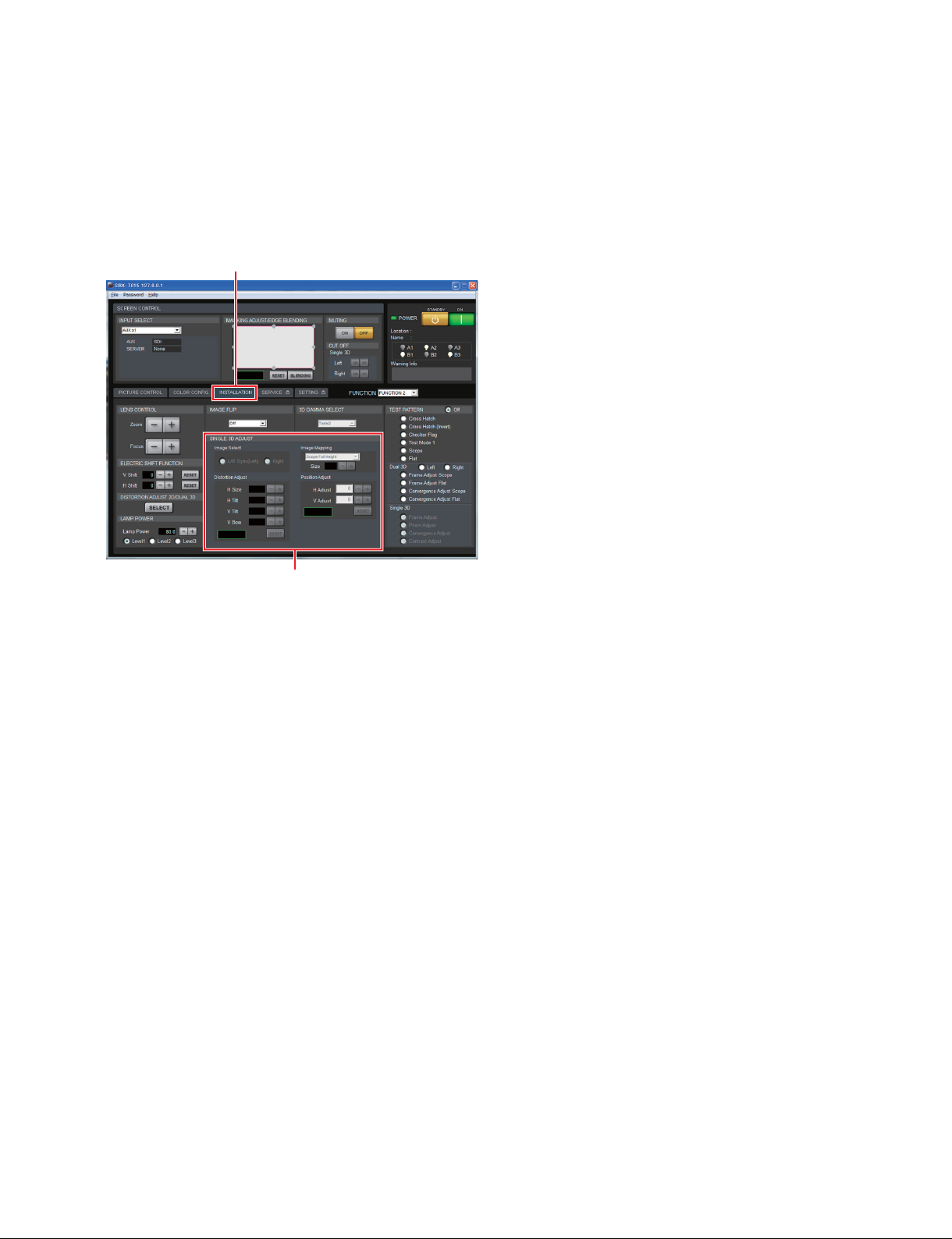
2-4-7. Image Mapping
When projecting the image from the server using the 3D lens, it is required to set the image mapping
according to the field angle of contents and the screen type.
1. Open an [INSTALLATION] screen. (Refer to steps 1 to 3 in Section 2-4-1.)
Screen example
[INSTALLATION] tab
[SINGLE 3D ADJUST]
2. Select the image mapping corresponding to the type of contents, the field angle of contents, and the
type of a screen in [SINGLE 3D ADJUST].
The image size can be adjusted using the [+] and [_] buttons of [Size] when you select the item
beginning with Scope.
SRX-T615
2-33 (E)
Page 58
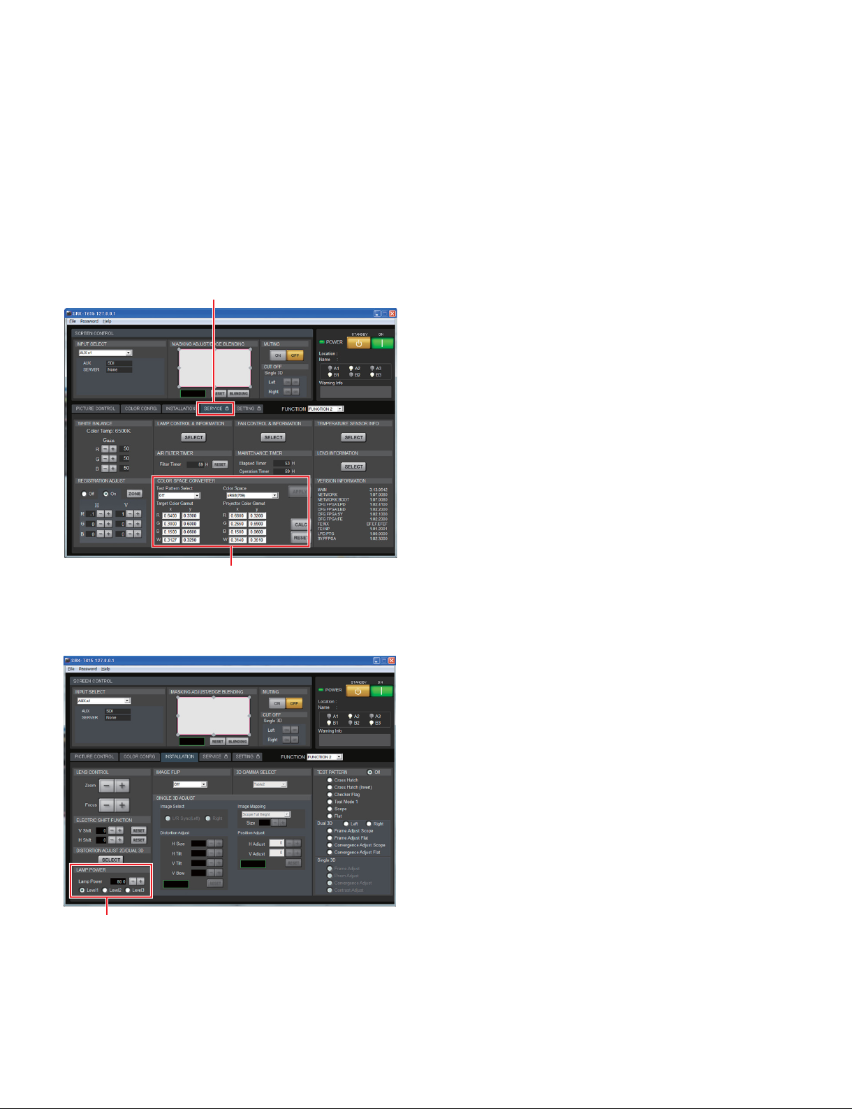
2-4-8. Brightness Adjustment
n
When the CSC adjustment is performed, the brightness changes slightly. After performing the CSC adjustment, adjust the brightness again.
1. Start the SRX Controller, then click the [SERVICE] tab. (Refer to Section 2-1-3.)
The [SERVICE] screen is displayed.
2. Select the “Gray-10” in [Test Pattern Select] of the [COLOR SPACE CONVERTER].
Screen example
[SERVICE] tab
[COLOR SPACE CONVERTER]
3. Click the [INSTALLATION] tab.
Screen example
[LAMP POWER]
4. Select an appropriate luminance level from the three levels in the [LAMP POWER].
t Level 3 is the brightest level.
5. Perform the fine adjustment using [+] and [_] buttons.
6. Check the brightness using the luminance meter.
2-34 (E)
SRX-T615
Page 59
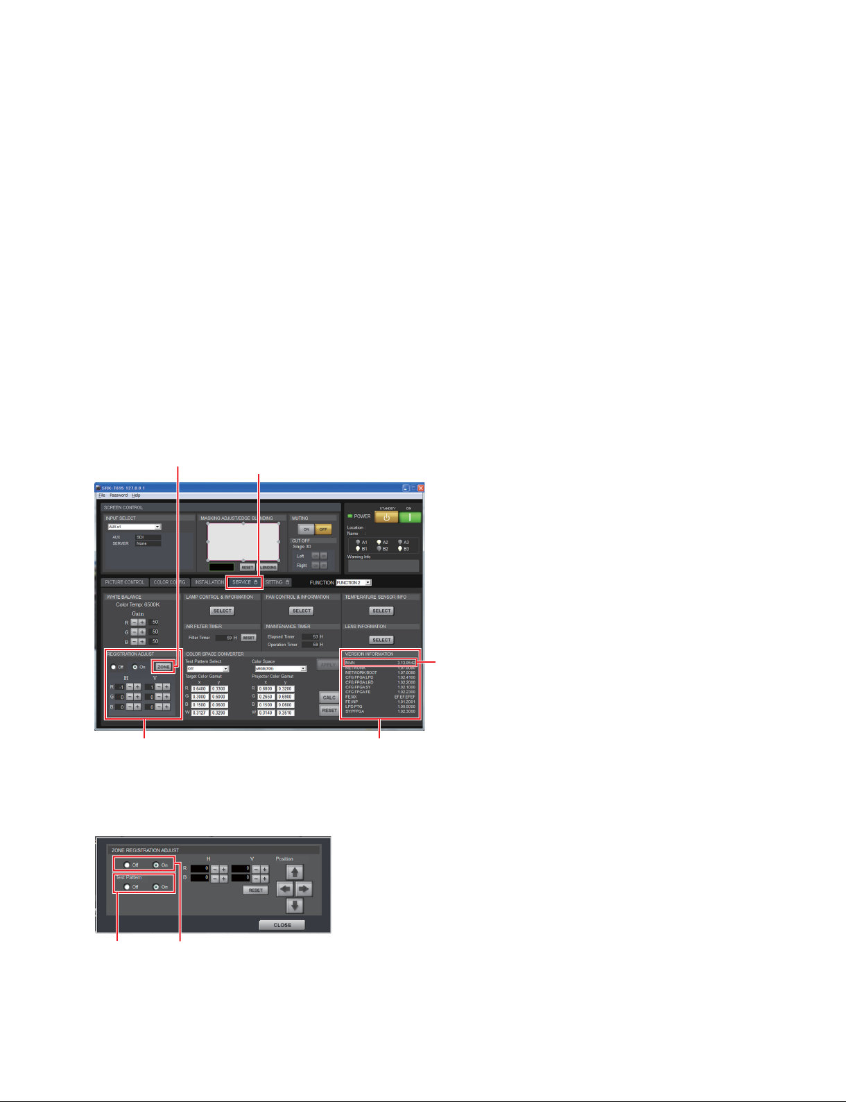
2-5. Registration Adjustment
Moves R (red), G (green), and B (blue) in the horizontal and vertical directions up to two pixels, one pixel
at a time so as to adjust registration. For details, refer to “5. SERVICE tab” in Section 2-1-4.
Also, perform the fine adjustment of the registration in the image peripheral portion as required. (Refer to
Section 2-5-1.)
2-5-1. Fine Adjustment of Registration
n
. First, perform the adjustment of R, G and B in [REGISTRATION ADJUST] of the [SERVICE] screen.
If the misregistration still remains, then perform the fine adjustment.
. The fine adjustment can be performed only when the projector MAIN version is 3.19.0600 or later. The
version can be confirmed in [MAIN] of [VERSION INFORMATION]. (Refer to the following screen.)
1. Start the SRX Controller, then click the [SERVICE] tab. (Refer to Section 2-1-3.)
The [SERVICE] screen is displayed.
button
[ZONE]
Screen example
[SERVICE] tab
Confirm the MAIN version.
[REGISTRATION ADJUST]
[VERSION INFORMATION]
2. Click the [ZONE] button.
The [ZONE REGISTRATION ADJUST] screen is displayed.
Screen example
[Test Pattern] [Zone Adjust]
SRX-T615
2-35 (E)
Page 60
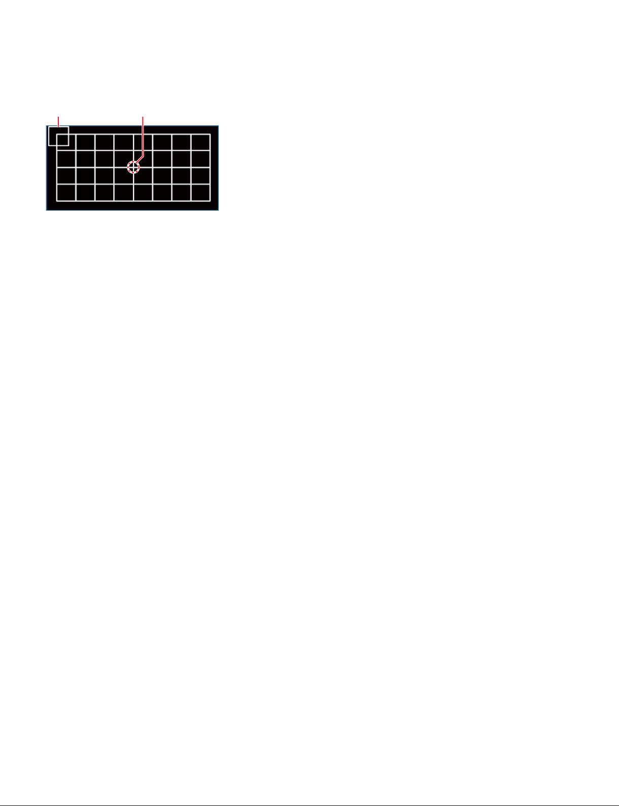
3. Click “On” of the radio button in [Test Pattern].
The following image is displayed on the screen.
Cursor Center of image
4. Move the cursor to the center of the image by clicking the [&]/[(]/[*]/[)] buttons.
5. Adjust R (Red) and B (Blue) images so that they are overlaid with G (Green) image using the [_]/[+]
buttons while viewing the images.
n
When you click the [_]/[+] buttons, the image moves in the direction based on the IMAGE FLIP Off
setting. Therefore, if the image is displayed in the state of IMAGE FLIP On, the image moves in the
opposite direction. (Even if the IMAGE FLIP is On, the cursor moves in the same direction as in the
state of IMAGE FLIP Off.)
t
The correction moving amount of the center in the horizontal direction is smaller than that of other
adjustment portions in the horizontal direction. This is not due to the abnormal state but because of
the specification.
Note on using the 3D lens
When adjusting the 3D image, hide one lens at a time. At that time, not only the image but also the
cursor moves reversely in both horizontal and vertical directions.
6. Move the cursor to the portion other than the center of the image by clicking the [&]/[(]/[*]/[)]
buttons.
7. Adjust the image using the [_]/[+] buttons in the same way as step 5.
8. Repeat steps 6 and 7 to adjust all portions.
9. When the adjustments of all portions are completed, click “Off” of the radio button in [Test Pattern].
10. Click “Off” of the radio button in [Zone Adjust].
n
If [Zone Adjust] was set to “Off”, the image for fine adjustment does not disappear from the screen. To
disappear the image, first set [Test Pattern] to “Off”, then set [Zone Adjust] to “Off”.
2-6. Color Space Conversion (CSC Adjustment)
The color space of this unit can be corrected for each color reproduction range.
n
. The CSC adjustment cannot be properly performed when gamma is misaligned.
It is recommended to perform gamma and uniformity adjustments in advance.
Perform the gamma adjustment of this unit using a gamma adjustment tool (PCAB-G).
.
Perform gamma and uniformity adjustments before CSC adjustment when changing the number of lamps.
The color may subtly vary depending on the number of lamps.
2-36 (E)
SRX-T615
Page 61
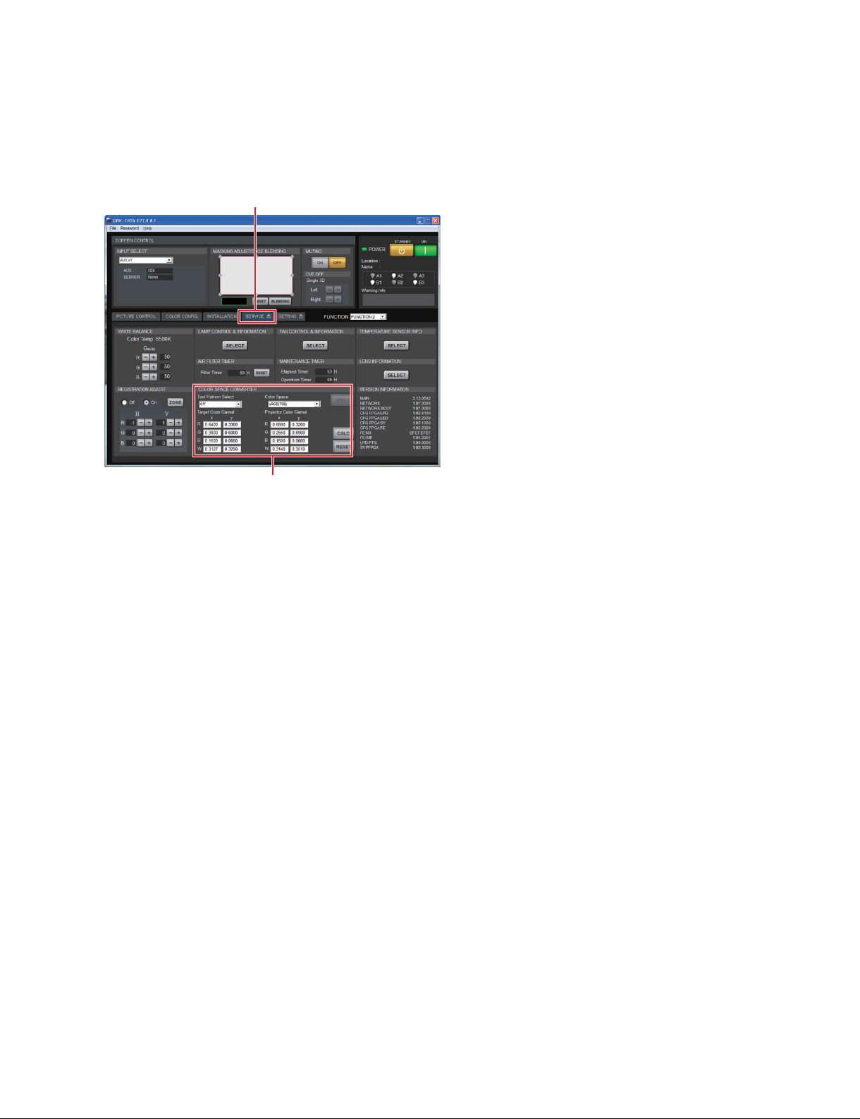
2-6-1. Correcting the Color Space “sRGB (709)”
1. Start the SRX Controller, then click the [SERVICE] tab. (Refer to Section 2-1-3.)
The [SERVICE] screen is displayed.
Screen example
[SERVICE] tab
[COLOR SPACE CONVERTER]
2. Select “sRGB (709)” in [Color Space] of the [COLOR SPACE CONVERTER].
3. Click the [RESET] button.
4. Click the [APPLY] button.
The color space function becomes OFF, and then the characteristics of this unit can be measured.
5. Select “Gray-10” in [Test Pattern Select].
6. Measure the value of x and y at the center of screen using the color meter.
7. Enter the measured value of x and y in the W box of “Projector Color Gamut” in [COLOR SPACE
CONVERTER].
8. Project “Red-1”, “Green-1”, and “Blue-1” in [Test Pattern Select] and measure the x and y values in
the center of the screen.
9. Enter the measured values in step 8 in the “R”, “G”, and “B” fields of [Projector Color Gamut].
10. Click the [CALC] button.
11. Click the [APPLY] button.
12.
Project “Gray-10”, “Red-1”, “Green-1”, and “Blue-1” again and measure the x and y values in the center of the screen.
13. Confirm that the error between the measured values in step 12 and the value of [Target Color Gamut]
is within ?0.005.
t
Gamma may be misaligned when specifications are not satisfied. Readjust the gamma in this case.
n
When adjusting color space DCDM or AdobeRGB, purchase an optional trimming filter kit and perform
the adjustment after replacement of a trimming filter. A correct color does not appear even if you perform
adjustment before replacement.
When replacing the trimming filter, contact your local Sony Sales Office/Service Center.
SRX-T615
2-37 (E)
Page 62
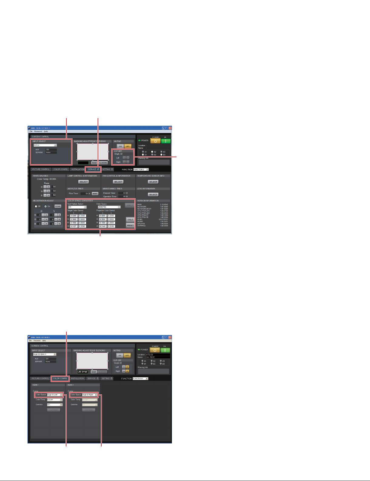
2-6-2. Correcting the Color Space “Single 3D”
The CSC for the left eye lens and right eye lens is corrected.
1. Start the SRX Controller.
2. Select “Single 3D HDMI-1(L/R)”, “Single 3D HDMI-2(L/R)”, or “Single 3D HDMI-1(L)/2(R)” in
[INPUT SELECT].
The current state enters a 3D mode.
3. Click the [SERVICE] tab.
[INPUT SELECT]
Screen example
[SERVICE] tab
[CUT OFF]
[COLOR SPACE CONVERTER]
4.
Select CSC for the left eye (such as Single 3D Left1) in [Color Space] of [COLOR SPACE CONVERTER].
5. Click the [ON] button in [Right] of [CUT OFF].
6. Perform steps 3 to 13 in Section 2-6-1.
7. Select CSC for the right eye (such as Single 3D Right1) in [Color Space] of [COLOR SPACE CONVERTER].
8. Click the [ON] button in [Left] of [CUT OFF].
9. Perform steps 3 to 13 in Section 2-6-1.
10. Click the [OFF] button in [Left] of [CUT OFF].
11. Click the [COLOR CONFIG.] tab, and then set [Color Space] for the left eye and right eye.
Screen example
[COLOR CONFIG.] tab
2-38 (E)
[Color Space] [Color Space]
SRX-T615
Page 63
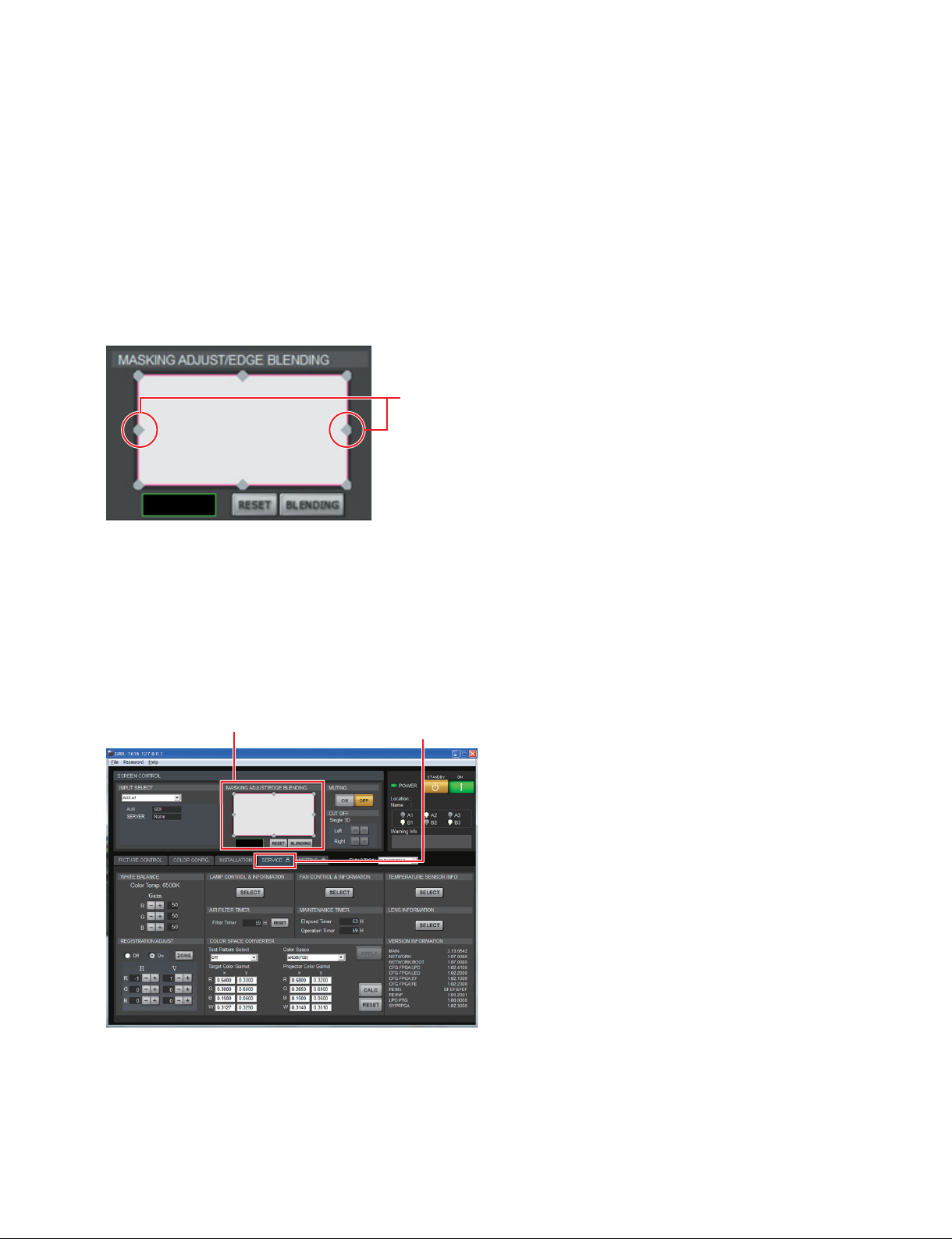
2-7. Edge Blending Adjustment
2-7-1. Edge Blending Setting
When projecting the image using multiple projectors, perform the edge blending adjustment to seamlessly
connect the images from the projectors. In this section, an example using the two projectors is described.
n
. When performing the blending adjustment, set the center adjustment points of the masking to “0”.
. Set the two projectors for blending adjustment as parallel as possible in the place vertical to the screen
so that the image distortion does not occur.
Set to “0” in these portions.
Set the side or width that you want to perform blending as follows.
. Blending in horizontal direction: Set [Horizontal] to “Blending width + 48”.
. Blending in vertical direction: Set [Vertical] to “Blending width + 50”.
In this section, an example of horizontal blending of the blending width 512 on the right side is explained.
1. Start the SRX Controller, then click the [SERVICE] tab. (Refer to Section 2-1-3.)
The [SERVICE] screen is displayed.
[MASKING ADJUST/EDGE BLENDING]
Screen example
[SERVICE] tab
SRX-T615
2-39 (E)
Page 64
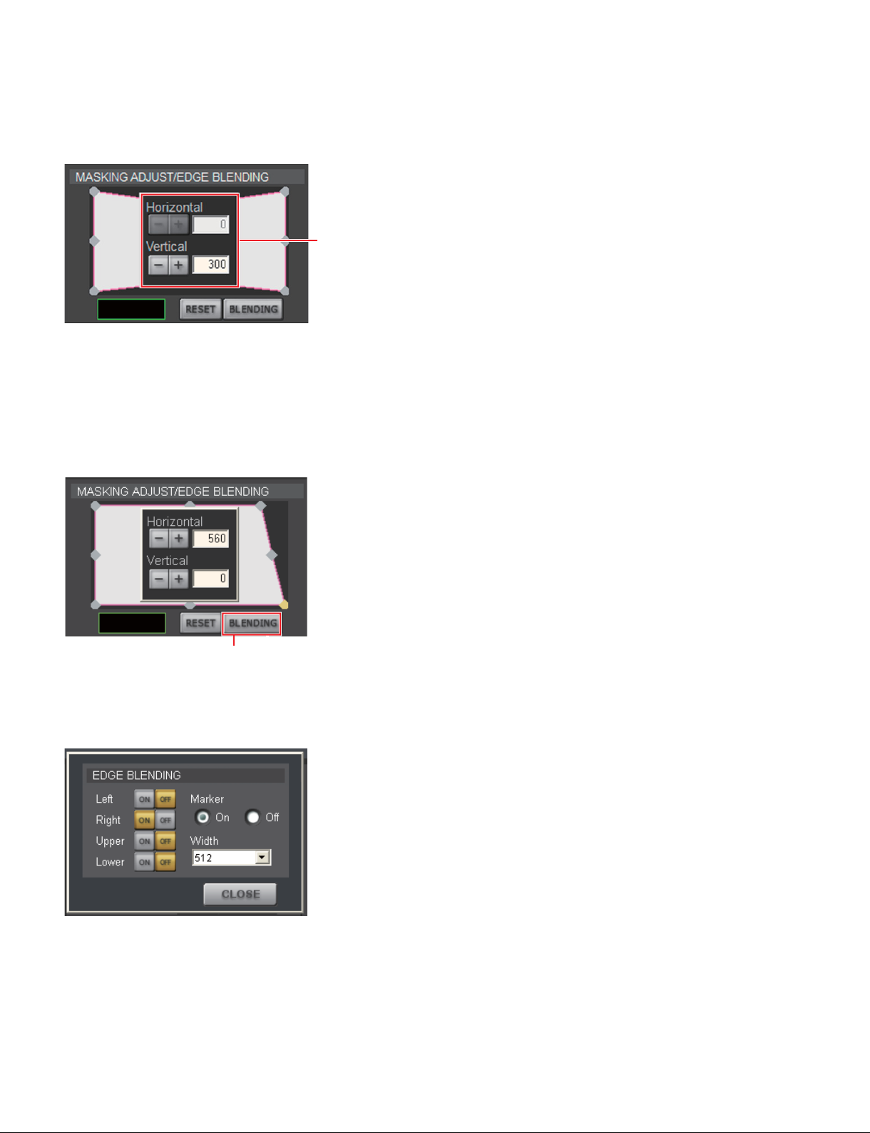
2. Double-click the upper right adjustment point of [MASKING ADJUST/EDGE BLENDING].
The adjustment screen is displayed.
Screen example
Adjustment screen
3. Enter “560” in [Horizontal].
Setting value: Blending width 512 + 48 = 560
4. Double-click the lower right adjustment point.
Enter “560” in [Horizontal].
Setting value: Blending width 512 + 48 = 560
Screen example
[BLENDING]
button
5. Click the [BLENDING] button.
The [EDGE BLENDING] screen is displayed.
6. Click the [ON] button in [Right] and select “512” in [Width].
Click “On” of the radio button in [Marker].
A green line is displayed at the start point of blending and a red line is displayed at the end point.
n
It is recommended to set [Upper] and [Lower] to “256” or “512”.
7. When the setting is completed, click the [CLOSE] button.
2-40 (E)
SRX-T615
Page 65
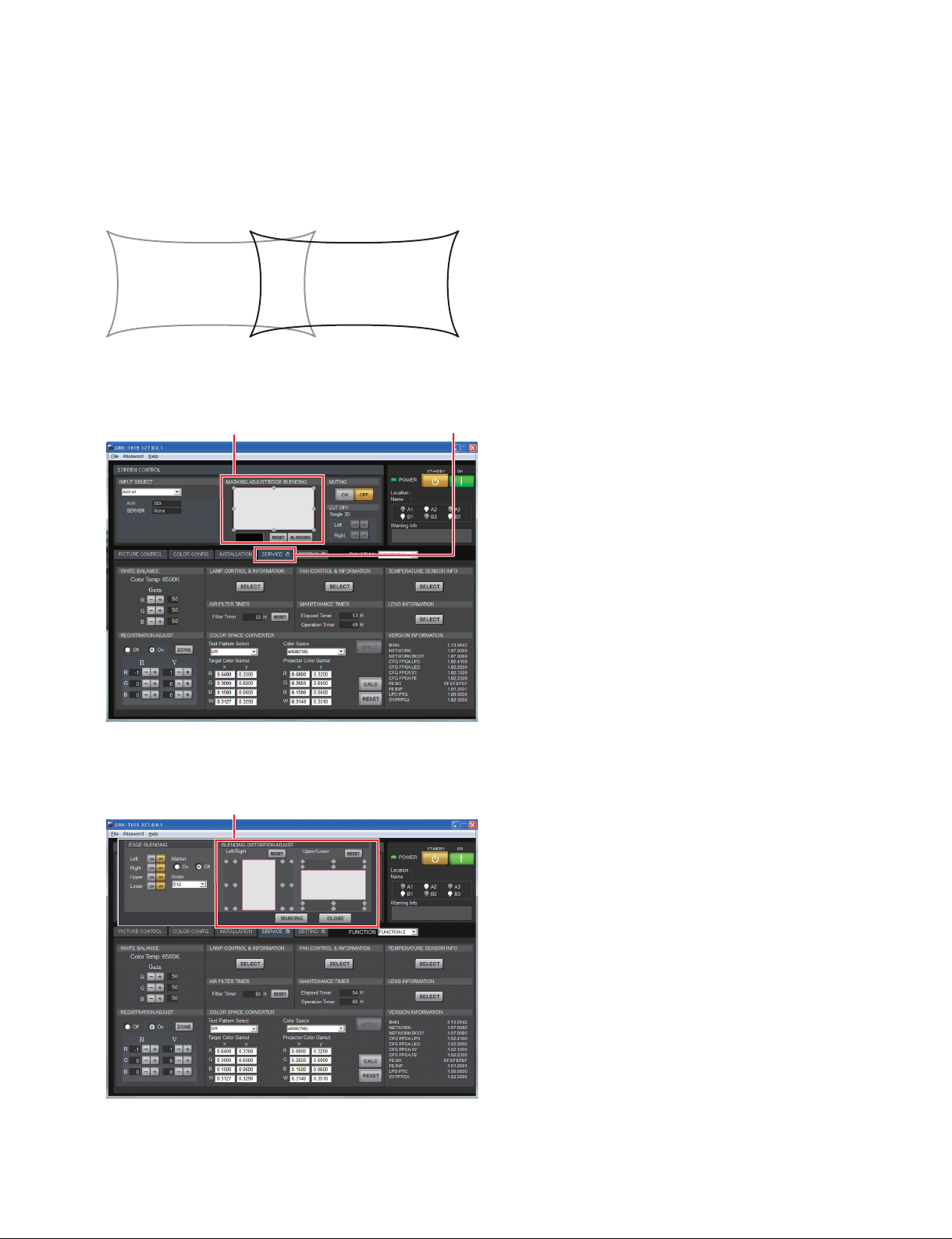
2-7-2. Correction of Distortion after Edge Blending Adjustment
After performing the blending adjustment of the two projectors, a misregistration as shown below may
occur due to the image distortion.
This image distortion is corrected.
1. Start the SRX Controller, then click the [SERVICE] tab. (Refer to Section 2-1-3.)
The [SERVICE] screen is displayed.
Screen example
[SERVICE] tab[MASKING ADJUST/EDGE BLENDING]
2. Click the [BLENDING] button of [MASKING ADJUST/EDGE BLENDING].
The [BLENDING DISTORTION ADJUST screen is displayed.
Screen example
SRX-T615
[BLENDING DISTORTION ADJUST]
t
The marks ◊ in [BLENDING DISTORTION ADJUST]
indicate the adjustment points.
2-41 (E)
Page 66
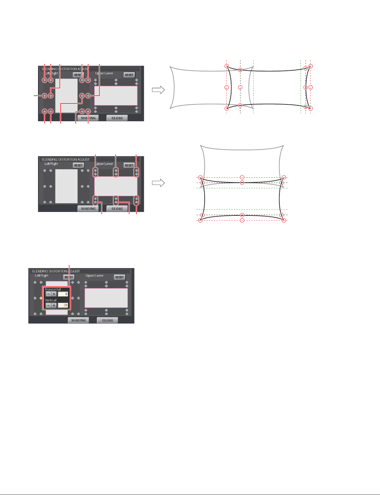
The adjustment points corresponding to the image are as shown below.
14 5 70 !-
1
4
7
0
2
36 8 9 !=
![
!;
!.
@=
!]
!'
!\
!,
@/@[@-
@]
3. Double-click the adjustment point ◊ of 5 first.
The adjustment screen is displayed.
Screen example
Adjustment screen
![
!;
!.
@=
2
3
5
69
!]
!'
@/
@[
!\
!,
@-
@]
8
!-
!=
4. Perform the adjustment so that the two images are connected without distortion by using the [_]/[+]
buttons.
5. Adjust the images at the adjustment points 8, !' and @/ in the same way.
The entire image is moved.
6. If the misregistration between the images still remains, perform the fine adjustment at other adjustment points.
7. Repeat steps 1 to 6 with the other projector.
2-42 (E)
SRX-T615
Page 67
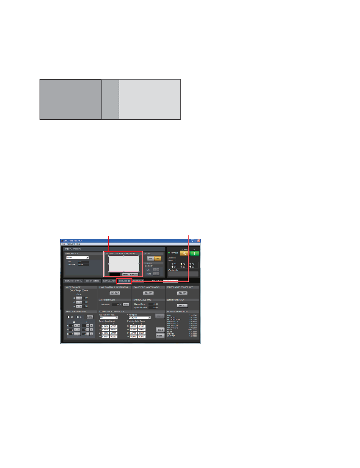
2-7-3. Color Matching of Edge Blending
After performing the color space conversion (CSC adjustment) of the two projectors, if the color of the
image overlaid portion is different from the color of other portion, perform this adjustment.
Image of projector A Image of projector B
n
. Perform this adjustment after completing “2-6. Color Space Conversion (CSC Adjustment)”. If the color
matching of edge blending is performed before the CSC adjustment, the entire adjustment may not be
able to be performed due to the lack of correction amount.
. Use one projector as the reference projector and adjust the other projector to the reference projector. Do
not change the values of the reference projector.
In this section, an example is described using the projector A as the reference projector.
1. Perform the following with the SRX Controller of the projector B.
(1) Start the SRX Controller, then click the [SERVICE] tab. (Refer to Section 2-1-3.)
The [SERVICE] screen is displayed.
Screen example
MASKING ADJUST/EDGE BLENDING
SERVICE
[
]
]tab[
SRX-T615
2-43 (E)
Page 68
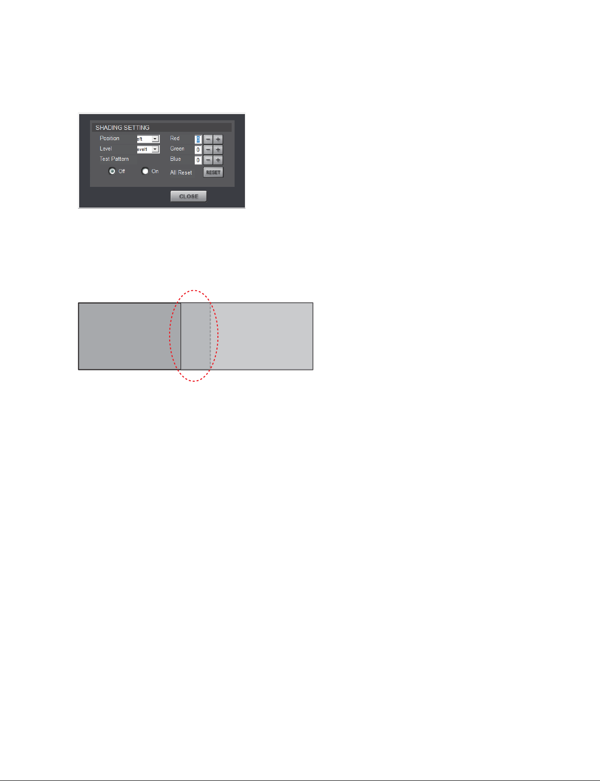
(2) Click the [SHADING] button of [MASKING ADJUST/EDGE BLENDING].
The [SHADING SETTING] screen is displayed.
Screen example
(3) Set “Position”. (Only for the projector B)
“Position” is set depending on where the image overlaid portion (encircled by dotted line) is
located in the image of the projector that is not the reference one (In this case, “Left” for the
projector B)
Image of projector A Image of projector B
(4) Click “On” of the radio button in [Test Pattern].
2. Perform (1), (2) and (4) in step 1 with the SRX Controller of the projector A.
In the projector A, the Position setting (3) is not performed.
3. Select [Level1] in [Level] for both projector A and projector B.
4. Visually adjust R (Red), G (Green) and B (Blue) of the projector B using the [_]/[+] buttons.
5. Adjust [Level2] to [Level8] by repeating steps 3 and 4.
6. After completing the adjustment, click “Off” of the radio button in [Test Pattern].
7. Click the [CLOSE] button.
2-44 (E)
SRX-T615
Page 69

Page 70

SRX-T615 (SY) J, E
9-878-503-02
Sony Corporation
Printed in Japan
2014. 7 32
©2013
 Loading...