

Page 1

DATA PROJECTOR
SRX-T420
INSTALLATION MANUAL
1st Edition
Page 2

!警告
このマニュアルは,サービス専用です。
お客様が,このマニュアルに記載された設置や保守,点検,修理などを行うと感電や火災,
人身事故につながることがあります。
危険をさけるため,サービストレーニングを受けた技術者のみご使用ください。
! WARNING
This manual is intended for qualifi ed service personnel only.
To reduce the risk of electric shock, fi re or injury, do not perform any servicing other than that
contained in the operating instructions unless you are qualifi ed to do so. Refer all servicing to
qualifi ed service personnel.
! WARNUNG
Die Anleitung ist nur für qualifi ziertes Fachpersonal bestimmt.
Alle Wartungsarbeiten dürfen nur von qualifi ziertem Fachpersonal ausgeführt werden. Um die
Gefahr eines elektrischen Schlages, Feuergefahr und Verletzungen zu vermeiden, sind bei
Wartungsarbeiten strikt die Angaben in der Anleitung zu befolgen. Andere als die angegeben
Wartungsarbeiten dürfen nur von Personen ausgeführt werden, die eine spezielle Befähigung
dazu besitzen.
! AVERTISSEMENT
Ce manual est destiné uniquement aux personnes compétentes en charge de l’entretien. Afi n
de réduire les risques de décharge électrique, d’incendie ou de blessure n’effectuer que les
réparations indiquées dans le mode d’emploi à moins d’être qualifi é pour en effectuer d’autres.
Pour toute réparation faire appel à une personne compétente uniquement.
安全のために,周辺機器を接続する際は,過大電圧を持
つ可能性があるコネクターを以下のポートに接続しない
でください。
: NETWORK コネクター
上記のポートについては本書の指示に従ってください。
For safety, do not connect the connector for peripheral device wiring that might have excessive voltage to the following port.
: NETWORK connector
Follow the instructions for the above port.
For kundene i Norge
Dette utstyret kan kobles til et IT-strømfordelingssystem.
SRX-T420
Page 3

Table of Contents
Manual Structure
Purpose of this manual .................................................................. 3
Related manuals ............................................................................ 3
Trademarks .................................................................................... 3
1. Installation
Outline ........................................................................................ 1-1
1-1. Removing/Installing the Cabinet Panel ........................... 1-1
1-1-1. Name of Cabinet Panel .......................................... 1-1
1-1-2. Panel (U7) Block Assembly ...................................1-2
1-1-3. Panel (U2) Block Assembly ...................................1-2
1-1-4. Panel (U3) .............................................................. 1-3
1-1-5. Panel (U6) .............................................................. 1-3
1-1-6. Panel (U5) .............................................................. 1-4
1-1-7. Panel (U1B) ........................................................... 1-4
1-1-8. Panel (U1) .............................................................. 1-5
1-2. Tilt Angle Adjustment .....................................................1-5
1-3. Installing the Duct ........................................................... 1-7
1-4. Installing the Projection Lens .......................................... 1-8
1-5. Installing the Lens Cover ................................................1-9
1-6. Installing the Lamp Bulb ............................................... 1-10
1-7. Installing the Optional Board to INPUT A, INPUT B,
INPUT C and INPUT D ................................................ 1-16
1-8. Interlock Terminal ......................................................... 1-22
1-9. Connecting and Wiring of External Device .................. 1-23
1-10. Connecting the Power Cord ..........................................1-24
1-11. About the Optional Accessories .................................... 1-26
1-12. Projection Distance Charts ............................................ 1-27
1-13. Dimensions ................................................................... 1-32
2. Adjustment
2-1. Installation of SRX Controller ........................................2-2
2-1-1. Startup .................................................................... 2-2
2-1-2. Function Memory ..................................................2-4
2-1-3. Log Function ..........................................................2-4
2-2. Setting of Projector.......................................................... 2-4
2-2-1. Owner Information ................................................2-5
2-2-2. Date & Time ..........................................................2-6
2-2-3. Network .................................................................2-7
2-2-4. Mail Report ............................................................ 2-8
2-2-5. PC Communication ................................................2-9
2-2-6. SNMP ................................................................... 2-10
2-2-7. Profi le ................................................................... 2-11
2-3. Optical Axis Adjustment of Lamp Bulb ........................ 2-12
2-4. Lens Adjustment (H Shift, V Shift, Zoom, and
Focus) ............................................................................ 2-15
2-5. Illumination Area Adjustment and
Registration Adjustment ................................................ 2-17
2-5-1. Illumination Area Adjustment ..............................2-17
2-5-2. Registration Adjustment ...................................... 2-19
2-6. Color Space Conversion (CSC Adjustment) .................2-20
2-6-1. Correcting the Color Space “sRGB (709)” or
“Adobe RGB” ...................................................... 2-20
2-6-2. Correcting the Color Space “DCDM” ................. 2-21
2-7. Functions of Each Window ........................................... 2-22
2-7-1. Common Items ..................................................... 2-22
2-7-2. INSTALLATION Window................................... 2-24
2-7-3. SERVICE Window .............................................. 2-26
2-7-4. SETTING Window .............................................. 2-28
3. Error Message
SRX-T420
1
Page 4

Page 5

Purpose of this manual
Related manuals
Manual Structure
This manual is the installation manual of Data Projector SRX-T420.
This manual is intended for use by trained system and service engineers, and describes the information for installation of the unit.
The DIF-188 board mounted on this unit as standard equipment is equivalent of
LKRI-005.
For the service information on the DIF-188 board, refer to the LKRI-005 service
manual.
The following manuals are prepared for this unit.
. Operating Instructions (supplied with this unit)
This manual describes the information required for the actual management and operation of this unit.
. Service Manual (available on request)
This manual describes the information for periodic maintenance and detailed service.
Trademarks
Trademarks and registered trademarks used in this manual are follows.
. Windows, Windows XP, and Windows Vista are registered trademarks of Micro-
soft Corporation in the United States and other countries.
. Intel and Pentium are registered trademarks of Intel Corporation or its subsidiaries
in the United States and other countries.
. Ethernet is a registered trademark of Xerox Corporation.
Other system names, product names, and company names appearing in this manual
are trademarks or registered trademarks of their respective holders.
SRX-T420
3
Page 6

Page 7

Section 1
Installation
Outline
The light source lamp bulb and projection lens are optionally available. You can incorporate them in the
system as required. For selecting the light source lamp and projection lens, contact your local Sony Sales
Offi ce/Service Center.
Before turning on the power of the main unit, perform the following procedure as required. (For details,
refer to the description of each section.)
For the removal of the cabinet panel required for each procedure, refer to Section 1-1.
m
. It is not required to perform steps 1 to 8 sequentially. However, do not perform the connection of power
cord in step 9 before completing steps 1 to 8.
. Be sure to remove the lamp bulb when moving this unit.
1. Adjust the tilt angle. (Refer to Section 1-2.)
2. Install the duct. (Refer to Section 1-3.)
3. Install the projection lens. (Refer to Section 1-4.)
4. Install the lens cover. (Refer to Section 1-5.)
5. Install the lamp bulb. (Refer to Section 1-6.)
6. Install the optional board to INPUT A and INPUT B slot. (Refer to Section 1-7.)
7. Connect the interlock connector. (Refer to Section 1-8.)
8. Connect and wire the external device. (Refer to Section 1-9.)
9. Connect the power cord. (Refer to Section 1-10.)
1-1. Removing/Installing the Cabinet Panel
n
The four (each two) keys of the panel (U7) block assembly and panel (U4) block assembly (420) described
in this section are supplied with this unit.
1-1-1. Name of Cabinet Panel
Panel (U7) block assembly
Panel (U1)
Panel (U1B)
Front side
Panel (U8)
Panel (U3)
Panel (U2) block assembly
Panel (U4) block assembly (420)
Panel (U4B) (420)
Rear side
Panel (U5)
Panel (U6)
SRX-T420
Fig. 1-1-1
1-1
Page 8

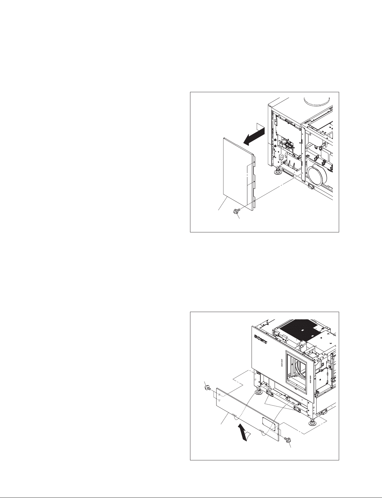
1-1-2. Panel (U7) Block Assembly
1. Release the lock on the panel (U7) block assembly.
2. Remove the panel (U7) block assembly in the direction
of the arrow with attention to the three hooks.
Panel (U7) block assembly
Hooks
3. To install, reverse the removal procedure.
1-1-3. Panel (U2) Block Assembly
Lock
Fig. 1-1-2
1. Remove the panel (U7) block assembly.
(Refer to Section 1-1-2.)
2. Loosen the two screws (with drop-safe), then remove
the two grilles.
3. Remove the fi ve screws, then raise the panel (U2)
block assembly in the direction of arrow with attention to the eight hooks.
4. Remove the panel (U2) block assembly in the direction
of arrow .
5. To install, reverse the removal procedure.
Hooks
Screws
Hooks
Screws
(with
drop-safe)
Hooks
Grilles
Panel (U2) block assembly
Fig. 1-1-3
1-2
SRX-T420
Page 9

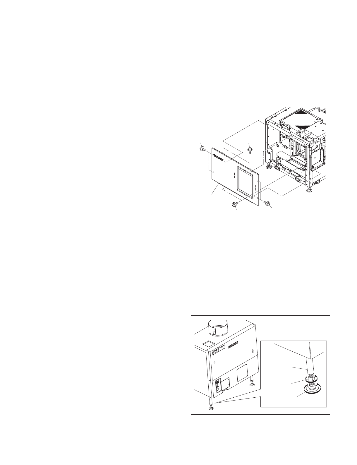
1-1-4. Panel (U3)
1. Remove the panel (U7) block assembly. (Refer to Section 1-1-2.)
2. Remove the panel (U2) block assembly. (Refer to Section 1-1-3.)
3. Remove the three screws, then remove the panel (U3)
in the direction of the arrow.
4. To install, reverse the removal procedure.
Panel (U3)
Screws
1-1-5. Panel (U6)
1. Remove the panel (U7) block assembly. (Refer to Section 1-1-2.)
2. Remove the fi ve screws, then raise the panel (U6) in
the direction of arrow with attention to the seven
hooks.
3. Remove the panel (U6) in the direction of arrow .
4. To install, reverse the removal procedure.
Hooks
Screws
Panel (U6)
Fig. 1-1-4
Hooks
Hooks
SRX-T420
Fig. 1-1-5
1-3
Page 10
1-1-6. Panel (U5)
1. Remove the panel (U7) block assembly. (Refer to Section 1-1-2.)
2. Remove the panel (U6). (Refer to Section 1-1-5.)
3. Remove the three screws, then remove the panel (U5)
in the direction of arrow.
4. To install, reverse the removal procedure.
Panel (U5)
Screws
1-1-7. Panel (U1B)
1. Remove the panel (U7) block assembly. (Refer to Section 1-1-2.)
2. Remove the panel (U2) block assembly. (Refer to Section 1-1-3.)
3. Remove the panel (U6). (Refer to Section 1-1-5.)
4. Remove the four screws, then remove the panel (U1B)
in the direction of arrow.
5. To install, reverse the removal procedure.
Screws
Fig. 1-1-6
Hooks
1-4
Panel (U1B)
Screws
Fig. 1-1-7
SRX-T420
Page 11
1-1-8. Panel (U1)
1. Remove the panel (U7) block assembly. (Refer to Section 1-1-2.)
2. Remove the panel (U2) block assembly. (Refer to Section 1-1-3.)
3. Remove the panel (U6). (Refer to Section 1-1-5.)
4. Remove the panel (U1B). (Refer to Section 1-1-7.)
5. Remove the eight screws, then remove the panel (U1).
6. To install, reverse the removal procedure.
Screws
Panel (U1)
1-2. Tilt Angle Adjustment
n
For further adjustment, “2-6. Field Angle Adjustment” is required.
In the case of tilt angle under 5 degrees:
Adjust the tilt angle using the adjuster in the lower portion of this unit.
Screws
Screws
Screws
Fig. 1-1-8
1. Loosen the nut.
2. Adjust the tilt angle by rotating the adjuster in the
lower portion of this unit.
3. Secure the adjuster by tightening the nut to the adjuster
pipe side.
SRX-T420
Adjuster pipe
Nut
Adjuster
Fig. 1-2a
1-5
Page 12
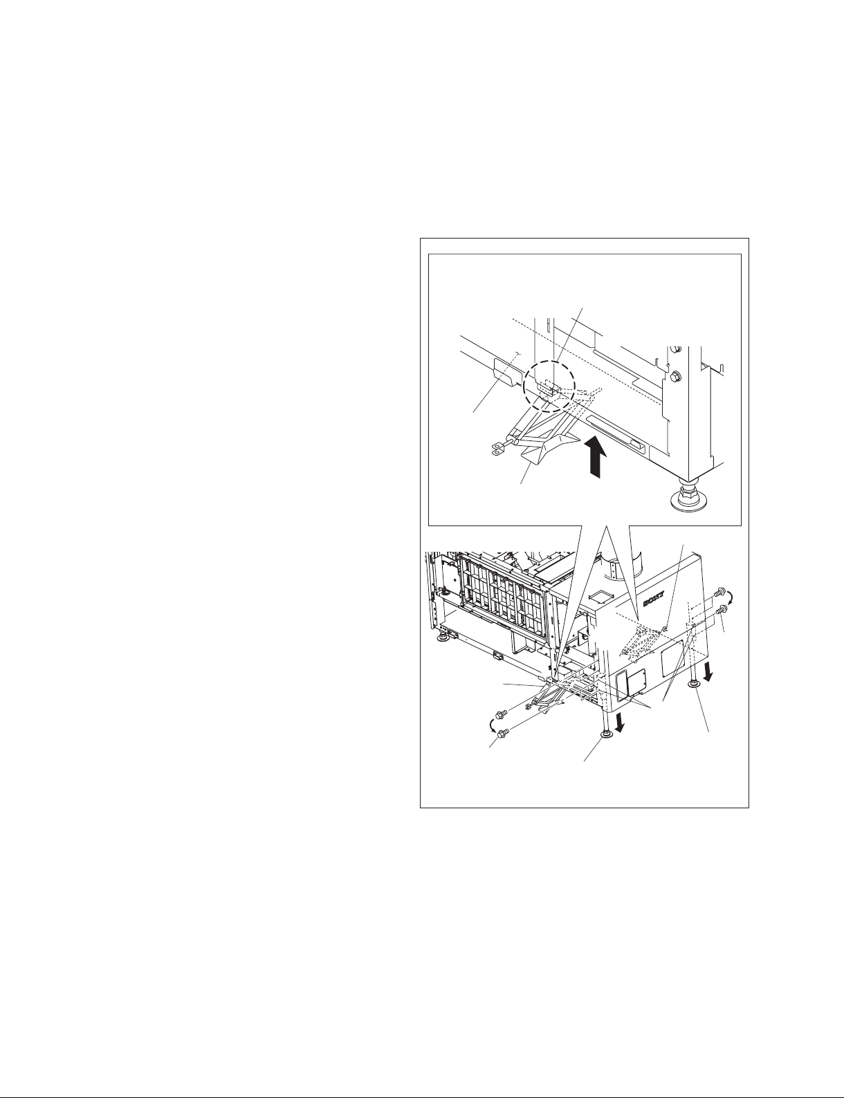
In the case of tilt angle from 5 to 10 degrees:
1. Remove the panel (U7) block assembly. (Refer to Section 1-1-2.)
2. Remove the panel (U2) block assembly. (Refer to Section 1-1-3.)
3. Remove the panel (U3). (Refer to Section 1-1-4.)
4. Remove the panel (U6). (Refer to Section 1-1-5.)
5. Remove the panel (U5). (Refer to Section 1-1-6.)
6. Set the tools such as jack at both sides of frame, then
raise the rear portion of the main unit.
7. Remove the four M8 bolts.
8. Move the adjuster pipe assembly downward and insert
the four M8 bolts into the four holes to secure it.
9. Lower the jack and attach the panel (U5), panel (U6),
panel (U3), panel (U2) block assembly and panel (U7)
block assembly.
n
When setting the jack, pay attention to
the holes on the bottom of flame.
Frame
Jack
Jack
M8 bolts
Jack
M8
bolts
Holes
Adjuster pipe
assembly
Adjuster pipe
assembly
Fig. 1-2b
1-6
SRX-T420
Page 13

In the case of fi xing this unit:
This unit can be fi xed to the fl oor using the anchor BKT.
When fi xing this unit, attach the anchor BKT to the adjust-
er as shown in the illustration.
Part name
Anchor BKT (optionally available): 3-294-224-01
Adjuster
Anchor BKT
1-3. Installing the Duct
Attach the commercially available 8-inch duct to the duct
connection of the panel (U8) of this unit.
n
When attaching the duct, be careful not to bend it so that
the exhaust air fl ows smoothly.
External fan (exhaust air) air volume specifi cation
The following exhaust air volume is required for the 8-inch
duct.
Exhaust air volume: 450 to 550 ft3/min
(12.7 to 15.6 m3/min)
Fig. 1-2c
8-inch duct
Duct connection
SRX-T420
Fig. 1-3
1-7
Page 14

1-4. Installing the Projection Lens
1. Attach the projection lens.
2. Align the notch of lens bracket with the line of projection lens and tighten the supplied four bolts in the order
from to .
3. Connect the three cables (focus, zoom and POTENTIO).
Tighten the bolts in the order from to .
Notch Line
n
Do not attach the lens cover before completing the lens
adjustment. (Refer to Section 2-3.)
Lens bracket
Projection lens
Bolts
Projection
lens
Pins
POTENTIO cable
Zoom cable
Focus cable
Fig. 1-4
1-8
SRX-T420
Page 15

1-5. Installing the Lens Cover
1. Attach the lens cover in the direction of arrow with
attention to the three hooks.
n
The lens covers are same parts, so they can be attached
both upper and lower.
Hook
Hook
Hook
Lens cover
Fig. 1-5a
2. Attach the lens cover in the direction of arrow with
attention to the three hooks.
n
When attaching the lens cover, align the four convex
portions with the four holes.
Hook
Lens cover
Hook
Hook
Lens cover
Convex portions
Holes
Hole
SRX-T420
Convex
portions
Hole
Lens cover
Fig. 1-5b
1-9
Page 16

1-6. Installing the Lamp Bulb
w
. Be sure to turn off the power of this unit before installing the lump bulb.
. Be sure that only the qualifi ed service personnel can install the lamp bulb. For the qualifi cation, please
contact your local Sony Sales Offi ce/Service Center.
. When installing the lamp bulb, be sure to wear the protection suit kit (J-7120-330-A (M size), J-7120-
340-A (L size), or J-7120-460-A (XL size)). Also, wear the shoes that cover the instep of the foot completely.
. Be extremely careful when handling the xenon lamp bulb because a high voltage is applied to it.
. Do not touch the lamp bulb with bear hands. Otherwise, it may break the lamp bulb.
Wearing of protection suit kit
1. Wear the jacket and trousers.
2. Wear the arm cover on both hands so that the wrists are
completely covered.
3. Wear the hood and attach the face shield.
4. Adjust the face shield to the head size using the adjuster on the back of the face shield.
5. Wear the glove on both hands.
Face shield
Hood
Adjuster
Face shield
Arm cover
Glove
Protection suit
Arm cover
Glove
Fig. 1-6a
1-10
SRX-T420
Page 17
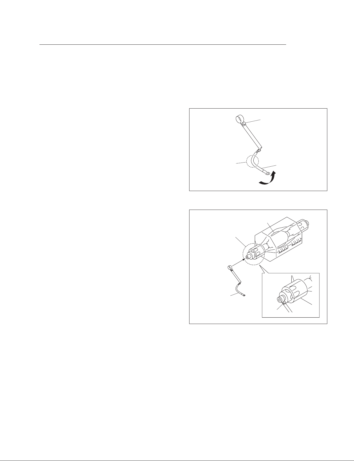
Procedure
m
. Keep the serial code label affi xed on the Operating Instructions of the lamp bulb which is required for
installation.
. Keep the materials such as packaging box, case, protection sheet because they are used when disposing
of the used lamp bulb.
1. Loosen the screw and bend portion A of the anode
harness.
Screw
2. Attach the anode harness to the anode side of the lamp
bulb, then tighten the screw.
(Tightening torque: 1.2 N.m)
Portion A
Anode side
Anode harness
Anode harness
Fig. 1-6b
Lamp bulb
Screw
Fig. 1-6c
SRX-T420
1-11
Page 18
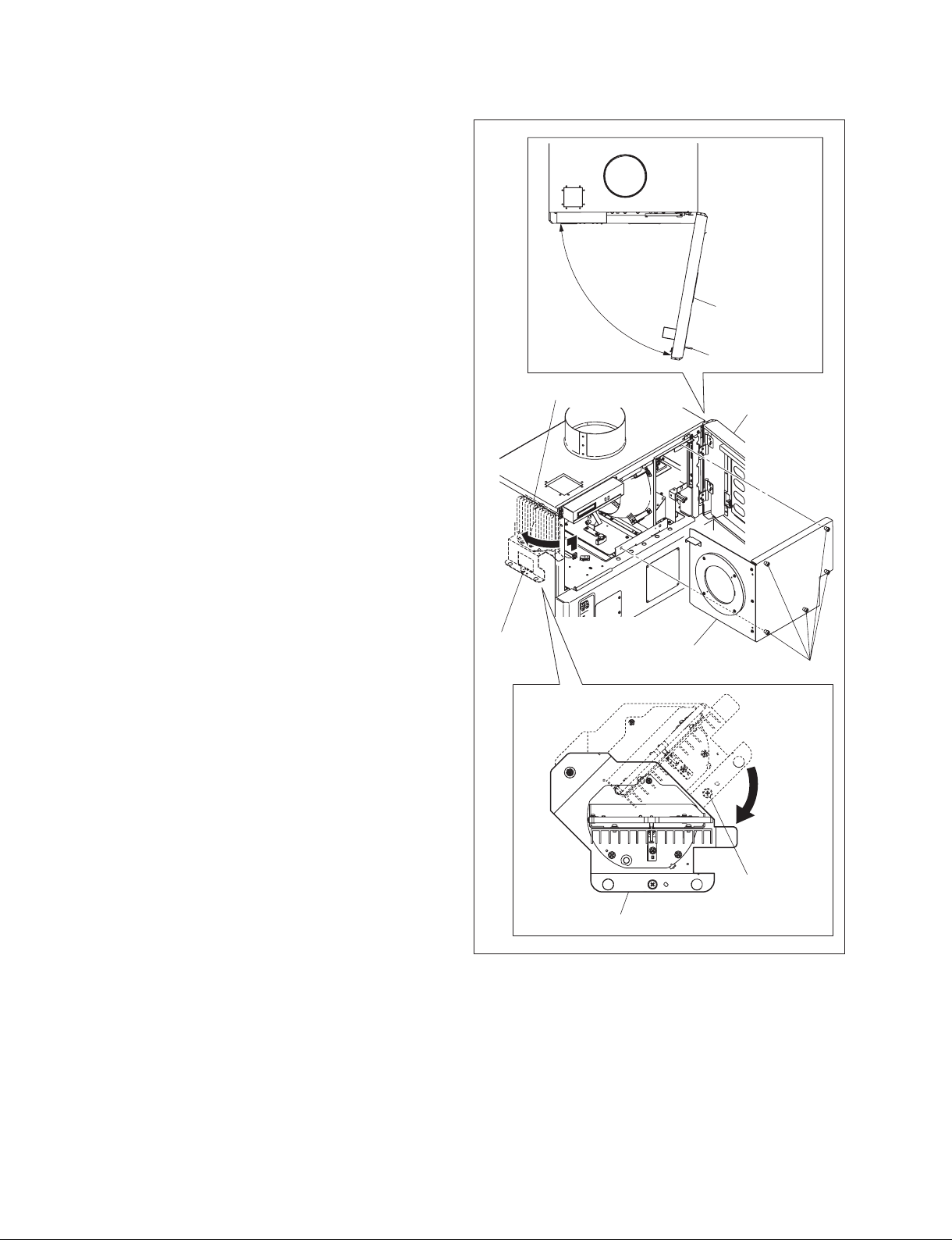
3. Release the lock, then open the panel (U4) block
assembly (420).
4. Loosen the screw (with drop-safe), then rotate the cold
mirror assembly in the direction of the arrow.
5. Loosen the fi ve screws (with drop-safe), then remove
the maintenance cover.
Panel (U4) block
assembly (420)
Lock
Cold mirror assembly
Screw
(with
drop-safe)
Panel (U4) block
assembly
Maintenance cover
Screws (with drop-safe)
1-12
Screw
(with drop-safe)
Cold mirror assembly
Fig. 1-6d
SRX-T420
Page 19

6. Remove the bolt from the anode terminal.
7. Loosen the hexagon socket set screw of the cathode
terminal.
Cathode terminal
Hexagon socket
set screw
8. Remove the plastic cover from the lamp bulb.
Anode terminal
Lamp bulb
Bolt
Fig. 1-6e
Plastic cover
SRX-T420
Fig. 1-6f
1-13
Page 20

9. Remove the protection sheet from the lamp bulb.
10. Loosen the knob, then move the anode holder in the
direction of the arrow.
11. Insert portion A of the lamp into the cathode terminal.
n
When attaching the lamp bulb, be careful not to dam-
age the refl ector portion. Also, be careful not to dam-
age the glass of lamp bulb. Otherwise, it may break the
lamp bulb.
12. Hold the cathode side of the lamp bulb fi rmly and raise
the anode side. Then, return the anode holder to the
original position and tighten the knob.
Lamp bulb
Protection sheet
Fig. 1-6g
Reflector portion
Cathode terminal
1-14
Anode
holder
Knob
Portion A
Lamp bulb
Fig. 1-6h
SRX-T420
Page 21

13. Place the anode side of the lamp bulb on the anode
holder.
14. Attach the anode harness to the anode terminal, then
tighten the bolt. (Tightening torque: 1.5 N.m).
n
After installing the anode harness separated lamp bulb,
if there is a clearance in portion A of the anode holder,
adjust it by bending the anode harness so that there is
no clearance between the anode holder and the lamp
bulb.
15. Tighten the hexagon socket set screw of the cathode
terminal.
(Tightening torque: 1.2 N.m)
n
Be sure that there is no clearance between the end face
of the cathode terminal and the surface C of the lamp
bulb.
16. Attach the panel (U4) block assembly (420) in the
reverse order of steps 3 to 5.
In the case of anode harness integrated lamp bulb
Lamp bulb
Anode
holder
Anode
harness
In the case of anode harness separated lamp bulb
Lamp bulb
Anode
holder
Anode
harness
No clearance
Portion A
Adjust by bending
this portion.
Cathode terminal
Hexagon socket
set screw
SRX-T420
Anode holder
Knob
Anode harness
Bolt
Anode terminal
Cathode terminalEnd face
Surface CLamp bulb
Fig. 1-6i
1-15
Page 22
1-7. Installing the Optional Board to INPUT A, INPUT B, INPUT C and
INPUT D
For any slots, the optional board, LKRI-003 or LKRI-005 can be installed.
The installing procedure for each slot is same.
n
For INPUT A slot, LKRI-005 is installed before shipment. Replace it as necessary.
Parts information
. Fixed Plate (HIF) 320: 4-159-161-01 (For LKRI-003)
. Fixed Plate (DIF) 320: 4-159-162-01 (For LKRI-005)
. Handle: 3-172-089-01 (Using 2 pcs)
Procedure (LKRI-003)
1. Remove the six screws, then remove the panel (HIF-44)
and fi nger holder (HIF).
LKRI-003
2. Attach the fi xed plate (HIF) 320 using the six screws
removed in step 1.
3. Attach the two handles to the fi xed plate (HIF) 320.
Handle
B3 x 8
B3 x 8
Finger holder (HIF)
Panel (HIF-44)
Fig. 1-7a
LKRI-003
Fixed plate (HIF) 320
Handle
Fig. 1-7b
1-16
SRX-T420
Page 23

4. Remove the six screws, then remove the all blank
panels.
n
Store the removed blank panel.
5. Remove the six screws, then remove the panel cover
(IF) 420.
When attaching the LKRI-003 to INPUT B slot
6. Insert the LKRI-003 board into INPUT B slot, and
connect it securely.
7. Attach the panel cover (IF) 420 using the twelve
screws.
n
Attach the blank panel to empty slot.
Panel cover (IF) 420
Blank panel
PSW4 x 10
PSW4 x 10
Fig. 1-7c
INPUT B
LKRI-003
SRX-T420
Panel cover (IF) 420
PSW4 x 10
Fig. 1-7d
1-17
Page 24

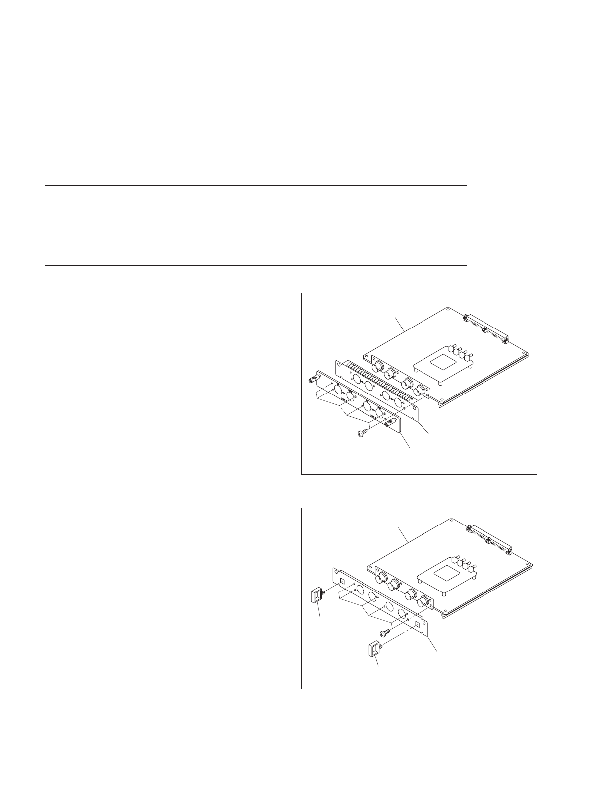
Procedure (LKRI-005)
1. Remove the two screws, then remove the panel
(DIF-188) and fi nger holder (DIF).
LKRI-005
2. Attach the fi xed plate (DIF) 320 using the two screws
removed in step 1.
3. Attach the two handles to the fi xed plate (DIF) 320.
Handle
B3 x 8
B3 x 8
Finger holder (DIF)
Panel (DIF-188)
Fig. 1-7e
LKRI-005
Fixed plate (DIF) 320
Handle
Fig. 1-7f
4. Remove the six screws, then remove the all blank
panels.
n
Store the removed blank panel.
5. Remove the six screws, then remove the panel cover
(IF) 420.
1-18
Panel cover (IF) 420
Blank panel
PSW4 x 10
PSW4 x 10
Fig. 1-7g
SRX-T420
Page 25

When attaching the LKRI-005 to INPUT B slot
6. Insert the LKRI-005 board into INPUT B slot, and
connect it securely.
7. Attach the panel cover (IF) using the twelve screws.
n
Attach the blank panel to empty slot.
INPUT B
LKRI-005
Panel cover (IF) 420
SRX-T420
PSW4 x 10
Fig. 1-7h
1-19
Page 26

Connection with each equipment
m
. Connect each equipment with the power turned off state.
. Use the connecting cables applicable to each terminal.
. Insert the plug securely. Incomplete connection may cause an image trouble.
When disconnecting the plug, be sure to hold the plug with your hand.
. Refer to the Operating Instructions of the equipment to be connected.
In case of LKRI-003
Input
BNC type (2)
HD-SDI: Serial digital (1.485 Gbps)
Compliant to SMPTE-292M/ITU-R,
BT709/BTA-S004
Dual-link HD-SDI: Serial digital (1.485 Gbps)
Compliant to SMPTE-372M
DC-SDI: Serial digital (1.485 Gbps)
Compliant to 23.98 PsF, 24 PsF, 24P
Output
BNC type (2)
Loop-through output
LKRI-003
To IN terminal
Quantization characteristics
10 bits/sampling
HD-SDI connecting cable
(optionally available)
HDCAM recorder/player, etc.
Fig. 1-7i
To HD-SDI output terminal
SRW-5000
HD DIGITAL VIDEO CASSETTE RECORDER
1-20
SRX-T420
Page 27
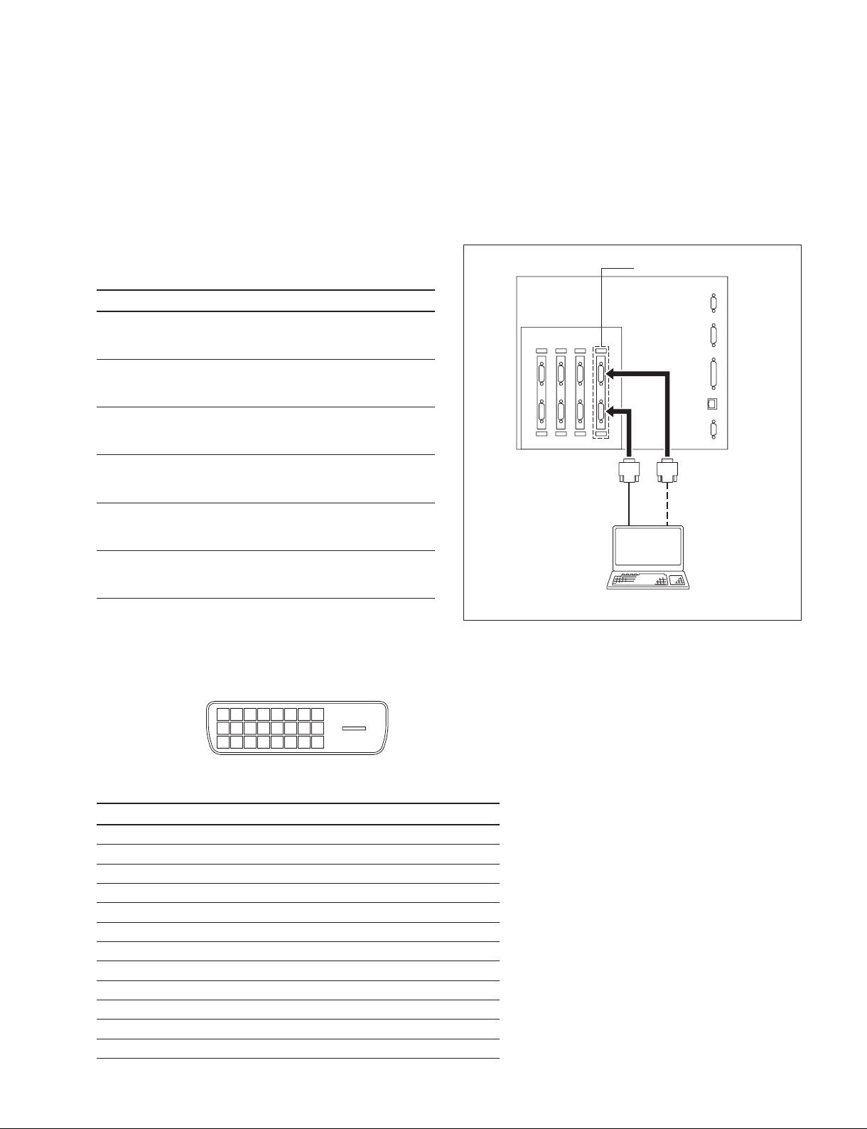
In case of LKRI-005
m
. For INPUT A slot, LKRI-005 is installed by default. However, LKRI-003 can be installed.
. When using a long cable, the image may not be displayed properly due to the signal attenuation.
. When the 10 bit single mode is selected, the DVI cable applicable to Dual-link is required.
1. Connect the commercially available DVI cable to the
terminal according to the input signal.
Input signal Used terminal
During normal operation
DVI1.0 compliant
Signal level: Full Range
10 bit signal of its own specifi cation
During input (10 bit twin mode)
Signal level: Full Range
10 bit signal of its own specifi cation
During input (10 bit single mode)
Signal level: Full Range
Used during signal input of DTV standard
DVI1.0 compliant
Signal level: Limited Range
10 bit signal of its own specifi cation
During input (10 bit twin mode)
Signal level: Limited Range
10 bit signal of its own specifi cation
During input (10 bit single mode)
Signal level: Limited Range
DVI-D terminal
DVI-D terminal
and AUX terminal
DVI-D terminal
DVI-D terminal
DVI-D terminal
and AUX terminal
DVI-D terminal
To DVI-D terminal
DVI-D cable
(optionally available)
To DVI output terminal
LKRI-005
Personal computer
To AUX terminal
Pin location
12345678
9 10111213141516
17 18 19 20 21 22 23 24
DVI-D terminal, AUX terminal
Pin No. Signal name Pin No. Signal name
1DATA2_ 13 DATA3+
2DATA2+ 14
3 GND 15 DDC_GND
4DATA4_ 16 HOTPLUG_DET
5DATA4+ 17 DATA0_
6 DDC_SCL 18 DATA0+
7 DDC_SDA 19 GND
8NC 20DATA5_
9DATA1_ 21 DATA5+
10 DATA1+ 22 GND
11 GND 23 CLK+
12 DATA3_ 24 CLK_
+5 V
Fig. 1-7j
SRX-T420
1-21
Page 28

1-8. Interlock Terminal
Shield case assembly (1)
Interlock
terminal
Pin location
87654321
15 14 13 12 11 10
Interlock terminal
1. Interlock Function
The SRX-T420 interlock function is enabled by making the two pins of the interlock terminal open or
short. The following two patterns can be used for the interlock function in the applicable serial.
9
Pattern 1
Normal: Open
Interlock: Short
Open/short between pin 4 and pin 5
9
15 14 13 12 11 10
87654321
1-22
SRX-T420
Page 29
Pattern 2
Normal: Short
Interlock: Open
Open/short between pin 5 and pin 6 with the pin 3 and pin 4 shorted state
9
15 14 13 12 11 10
87654321
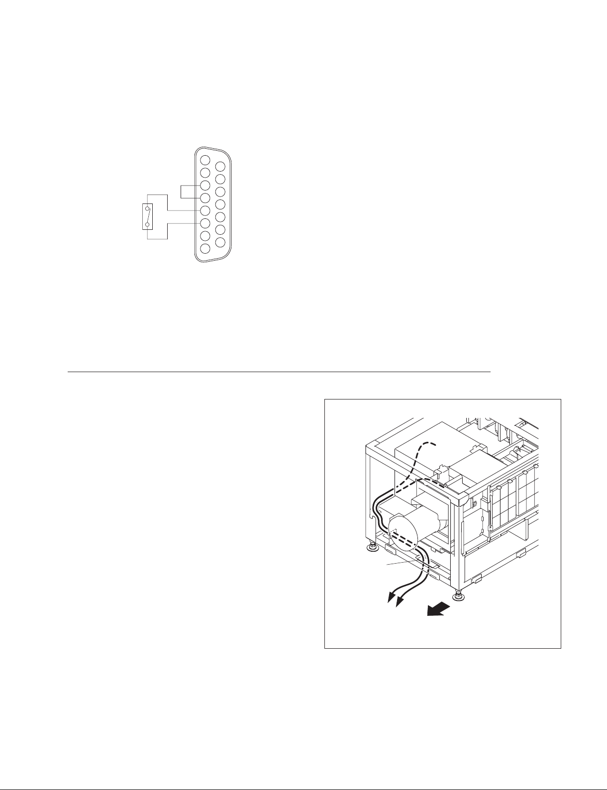
1-9. Connecting and Wiring of External Device
w
Do not plug the power cord into the power supply when performing the following wiring operations.
Signal cable wiring
When connecting to external device to this unit, connect by
routing the cable through the hole of the front side.
Hole
External device
Front side
Fig. 1-9
SRX-T420
1-23
Page 30
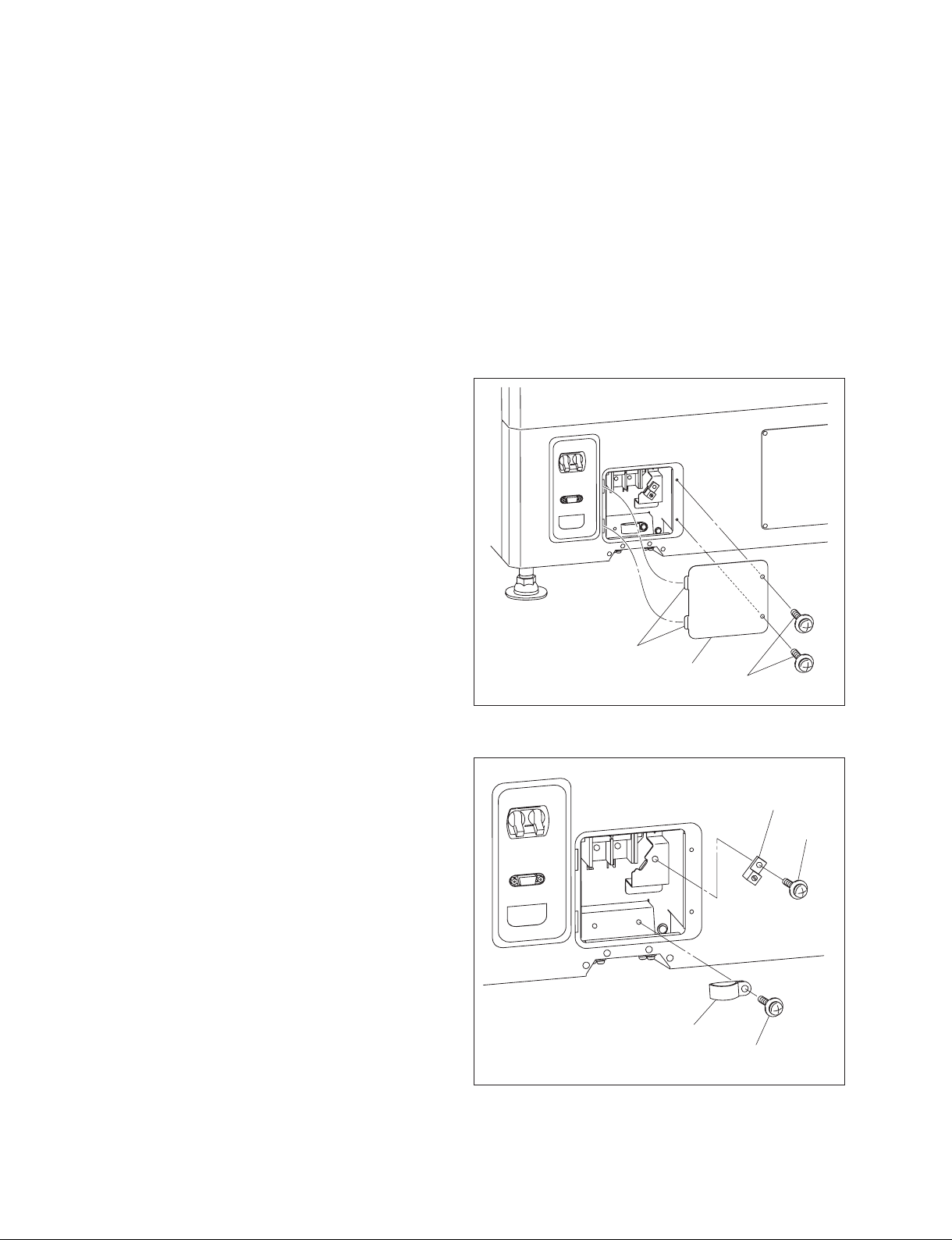
1-10. Connecting the Power Cord
Use the 3-core power cord that satisfy AWG 8, 250 V rated and 40 A rated.
Connect the power cord to the AC IN terminal block on the rear side of this unit, referring the following
procedure.
w
. Connection of the main power and the electric wiring work should be done by qualifi ed electricians
only.
. Do not plug the power cord into the power supply before completing all of the following connecting op-
erations.
1. Remove the two screws.
2. Remove the terminal block cover with attention to the
two hooks.
3. Remove the screw, then remove the cable clamp.
4. Remove the screw, then remove the ground terminal.
Hooks
Terminal block cover
Screws
Fig. 1-10a
Ground terminal
Screw
Cable clamp
Screw
Fig. 1-10b
1-24
SRX-T420
Page 31

5. Pack by soldering the end of the ground wire.
6. Attach the ground terminal removed in step 4 to the
ground wire, then fi x it with the screw.
7. Route the cable through the lower hole of the terminal
block, then fi x each terminal by screw.
8. Fix the cable with the cable clamp and screw.
9. Attach the terminal block cover.
Screw
Pack by soldering
Ground terminal
Ground wire
Fig. 1-10c
Ground terminal
Screws
Fig. 1-10d
Cable clamp
Screw
SRX-T420
1-25
Page 32

1-11. About the Optional Accessories
The projection lamps of this projector are provided as optional accessories. Install the lamp houses to the
projector according to your model.
For versatile use of the projector, the optional accessories mentioned below can be used with the projector. Select to use them according to your system requirements.
. For details on optional accessories, refer to the relevant Operating Instructions.
Lamp
LKRX-2042A
Projection lens
. LKRL-Z111C (with memory function)
. LKRL-Z114C (with memory function)
. LKRL-Z116C (with memory function)
. LKRL-Z117 (with memory function)
. LKRL-Z119 (with memory function)
. LKRL-Z122 (with memory function)
. LKRL-Z115
. LKRL-Z140
. LKRL-90 (fi xed focus lens)
Input board
. LKRI-003 HD-SDI/DC-SDI (4:4:4) input board
. LKRI-005 HDCP DVI board
1-26
SRX-T420
Page 33

1-12. Projection Distance Charts
Screen
Center of screen
L (Suitable distance)
The alphabetical characters in this section indicate the following measurements:
W: Screen width (unit: mm)
D: Screen diagonal length (unit: inch)
L (min): Minimum distance between the center of lens and screen
L (max): Maximum distance between the center of lens and screen
H: Screen height (different from the aspect ratio of the projected image)
The distance between the lens and the screen varies depending on the attached lens, type of the input
signal or size of the projected image. Choose the most suitable distance (L) depending on the screen size
(W or D).
Center of lens
The formula for calculating the projection distance from the screen width (W, unit: mm) is as follows:
Type of lens Projection distance
calculation formula when
inputting a 4K x 2K signal
L (min) L (max) L (min) L (max) L (min) L (max)
LKRL-Z115 1.48 x W 1.8 x W 1.58 x W 1.92 x W 2.1 x W 2.56 x W
LKRL-Z117 1.69 x W 2.38 x W 1.8 x W 2.53 x W 2.41 x W 3.38 x W
LKRL-Z119 1.78 x W 2.93 x W 1.89 x W 3.13 x W 2.53 x W 4.16 x W
LKRL-Z122 2.19 x W 3.99 x W 2.33 x W 4.26 x W 3.12 x W 5.68 x W
LKRL-Z140 3.75 x W 7.07 x W4 x W 7.54 x W 5.34 x W 10 x W
LKRL-Z111C 1.07 x W 1.71 x W 1.14 x W 1.82 x W 1.52 x W 2.43 x W
LKRL-Z114C 1.35 x W 1.98 x W 1.44 x W 2.12 x W 1.93 x W 2.82 x W
LKRL-Z116C 1.51
LKRL-90 0.897 x W 0.957 x W 1.28 x W
x W 2.3 x W 1.61 x W 2.45 x W 2.15 x W 3.27 x W
Projection distance
calculation formula when
inputting a 16:9 signal
Projection distance
calculation formula when
inputting a 4:3 signal
SRX-T420
1-27
Page 34

The formula for calculating the projection distance from the screen diagonal length (D, unit: inch) is as
follows:
Type of lens Projection distance
calculation formula when
inputting a 4K x 2K signal
Projection distance
calculation formula when
inputting a 16:9 signal
Projection distance
calculation formula when
inputting a 4:3 signal
L (min) L (max) L (min) L (max) L (min) L (max)
LKRL-Z115 1.31 x D 1.59 x D 1.37 x D 1.67 x D 1.68 x D 2.05 x D
LKRL-Z117 1.49 x D 2.1 x D 1.57 x D 2.21 x D 1.93 x D 2.7 x D
LKRL-Z119 1.57 x D 2.59 x D 1.65 x D 2.72 x D 2.03 x D 3.33 x D
LKRL-Z122 1.94 x D 3.53 x D 2.03 x D 3.71 x D 2.5 x D 4.54 x D
LKRL-Z140 3.31 x D 6.25 x D 3.48 x D 6.57 x D 4.27 x D 8.03 x D
LKRL-Z111C 0.942 x D 1.51 x D 0.99 x D 1.59 x D 1.22 x D 1.94 x D
LKRL-Z114C 1.2 x D 1.75 x D 1.26 x D 1.84 x D 1.54 x D 2.26 x D
LKRL-Z116C 1.34
x D 2.03 x D 1.41 x D 2.14 x D 1.72 x D 2.62 x D
LKRL-90 0.793 x D 0.834 x D 1.02 x D
The projection distance (L) that is decided by the screen width (W) is as shown below.
For the projection distance charts of the optional lenses not mentioned below, refer to the mounting
instructions supplied with each lens.
Using the LKRL-Z115 projection lens
When projecting a 4096-pixel (4K x 2K) image at the maximum horizontal picture element
Unit: mm (inches)
W 4500 5000 6000 7000 8000 9000 10000 12000 14000 16000
(177 1/5) (196 6/7) (236 2/9) (275 3/5) (315) (354 1/3) (393 5/7) (472 4/9) (551 1/6) (630)
L (min) 6554 7295 8778 10261 11743 13226 14709 17674 20639 23605
(258) (287 2/9) (345 3/5) (404) (462 1/3) (520 5/7) (579) (695 5/6) (812 4/7) (929 1/3)
L (max) 8056 8964 10780 12596 14412 16228 18044 21676 25308 28940
(317 1/6) (353) (424 2/5) (496) (567 2/5) (638 8/9) (710 2/5) (853 2/5) (996 3/8) (1139 3/8)
a)
2373 2637 3164 3691 4219 4746 5273 6328 7383 8438
H1
(93 3/7) (103 4/5) (124 4/7) (145 1/3) (166) (186 6/7) (207 5/8) (249 1/7) (290 2/3) (332 1/5)
b)
1883 2092 2510 2929 3347 3766 4184 5021 5858 6695
H2
(74 1/8) (82 3/8) (98 5/6) (115 1/3) (131 7/9) (148 1/4) (164 3/4) (197 2/3) (230 5/8) (263 4/7)
mm:
L (min) = (W _ 79.675) / 0.67446 L (max) = (W _ 63.762) / 0.55067
H1 = W x 0.52730 H2 = W x 0.41840
inch:
L (min) = (W _ 3.1368) / 0.67446 L (max) = (W _ 2.5103) / 0.55067
H1 = W x 0.52730 H2 = W x 0.41840
a) Screen height when projecting a 4096 x 2160-pixel (4K single screen) image on the screen.
b) Screen height when projecting a 4096 x 1714-pixel (aspect ratio 2.39:1) image on the screen.
1-28
SRX-T420
Page 35

When projecting a 3840-pixel (aspect ratio 16:9) image at the maximum horizontal picture element
Unit: mm (inches)
W 4500 5000 6000 7000 8000 9000 10000 12000 14000 16000
(177 1/6) (196 6/7) (236 2/9) (275 3/5) (315) (354 1/3) (393 5/7) (472 4/9) (551 1/6) (630)
L (min) 7001 7791 9373 10955 12537 14118 15700 18863 22027 25190
(275 5/8) (306 3/4) (369) (431 2/7) (493 4/7) (555 5/6) (618 1/9) (742 2/3) (867 1/5) (991 3/4)
L (max) 8600 9568 11505 13442 15379 17316 19253 23127 27000 30874
(338 4/7) (376 5/7) (453) (529 2/9) (605 1/2) (681 3/4) (758) (910 1/2) (1063) (1215 1/2)
a)
2531 2813 3375 3938 4500 5063 5625 6750 7875 9000
H1
(99 2/3) (110 3/4) (132 7/8) (155) (177 1/6) (199 1/3) (221 1/2) (265 3/4) (310) (354 1/3)
b)
2432 2703 3243 3784 4324 4865 5405 6486 7568 8649
H2
(95 3/4) (106 2/5) (127 2/3) (149) (170 1/4) (191 1/2) (212 4/5) (255 3/8) (298) (340 1/2)
mm:
L (min) = (W _ 73.944) / 0.63223 L (max) = (W _ 59.873) / 0.51629
H1 = W x 0.56250 H2 = W x 0.54050
inch:
L (min) = (W _ 2.9112) / 0.63223 L (max) = (W _ 2.3572) / 0.51629
H1 = W x 0.56250 H2 = W x 0.54050
a) Screen height when projecting a 3840 x 2160-pixel (aspect ratio 16:9) image.
b) Screen height when projecting a 3996 x 2160-pixel (aspect ratio 1.85:1) image.
When projecting a 2880-pixel (aspect ratio 4:3) image at the maximum horizontal picture element
Unit: mm (inches)
W 3500 4000 4500 5000 6000 7000 8000 9000 10000 12000
(137 4/5) (157 1/2) (177 1/6) (196 6/7) (236 2/9) (275 3/5) (315) (354 1/3) (393 5/7) (472 4/9)
L (min) 7271 8326 9381 10436 12547 14657 16767 18878 20988 25208
(286 1/4) (327 4/5) (369 1/3) (410 8/9) (494) (577) (660 1/8) (743 1/5) (826 2/7) (992 4/9)
L (max) 8922 10213 11504 12795 15377 17959 20541 23123 25705 30869
(351 1/4) (402) (453) (503 3/4) (605 2/5) (707) (808 5/7) (910 1/3) (1012) (1215 1/3)
a)
H
2625 3000 3375 3750 4500 5250 6000 6750 7500 9000
(103 1/3) (118 1/9) (132 7/8) (147 2/3) (177 1/6) (206 2/3) (236 2/9) (265 3/4) (295 2/7) (354 1/3)
mm: L (min) = (W _ 54.449) / 0.47387 L (max) = (W _ 44.662) / 0.38729 H = W x 0.75000
inch: L (min) = (W _ 2.1436) / 0.47387 L (max) = (W _ 1.7583) / 0.38729 H = W x 0.75000
a) Screen height when projecting a 2880 x 2160-pixel (aspect ratio 4:3) image.
SRX-T420
1-29
Page 36

Using the LKRL-Z140 projection lens
When projecting a 4096-pixel (4K x 2K) image at the maximum horizontal picture element
Unit: mm (inches)
W 4500 5000 6000 7000 8000 9000 10000
(177 1/6) (196 6/7) (236 2/9) (275 3/5) (315) (354 1/3) (393 5/7)
L (min) 16937 18792 22502 26212 29922 33632 37342
(666 4/5) (739 5/6) (885 8/9) (1032) (1178) (1324) (1470 1/7)
L (max) 31943 35466 42512 49558 56604 63649 70695
(1257 3/5) (1396 2/7) (1673 2/3) (1951) (2228 1/2) (2505 7/8) (2783 2/7)
a)
H1
2373 2637 3164 3691 4219 4746 5273
(93 3/7) (103 4/5) (124 4/7) (145 1/3) (166) (186 6/7) (207 5/8)
b)
1883 2092 2510 2929 3347 3766 4184
H2
(74 1/8) (82 3/8) (98 5/6) (115 1/3) (131 7/9) (148 1/4) (164 3/4)
mm:
L (min) = (W + 65.304) / 0.26955 L (max) = (W + 33.615) / 0.14193
H1 = W x 0.52730 H2 = W x 0.41840
inch:
L (min) = (W + 2.5710) / 0.26955 L (max) = (W + 1.3234) / 0.14193
H1 = W x 0.52730 H2 = W x 0.41840
a) Screen height when projecting a 4096 x 2160-pixel (4K single screen) image.
b) Screen height when projecting a 4096 x 1714-pixel (aspect ratio 2.39:1) image.
When projecting a 3840-pixel (aspect ratio 16:9) image at the maximum horizontal picture element
Unit: mm (inches)
W 4500 5000 6000 7000 8000 9000 10000
(177 1/6) (196 6/7) (236 2/9) (275 3/5) (315) (354 1/3) (393 5/7)
L (min) 18062 20042 24002 27961 31921 35881 39841
(711) (789) (945) (1100 5/6) (1256 3/4) (1412 5/8) (1568 1/2)
L (max) 34047 37803 45317 52830 60343 67857 75370
(1340 3/7) (1488 1/3) (1784 1/8) (2080) (2375 3/4) (2671 1/2) (2967 1/3)
a)
2531 2813 3375 3938 4500 5063 5625
H1
(99 2/3) (110 3/4) (132 7/8) (155) (177 1/6) (199 1/3) (221 1/2)
b)
H2
2432 2703 3243 3784 4324 4865 5405
(95 3/4) (106 2/5) (127 2/3) (149) (170 1/4) (191 1/2) (212 4/5)
mm:
L (min) = (W + 61.345) / 0.25254 L (max) = (W + 31.485) / 0.13310
H1 = W x 0.56250 H2 = W x 0.54050
inch:
L (min) = (W + 2.4152) / 0.25254 L (max) = (W + 1.2396) / 0.13310
H1 = W x 0.56250 H2 = W x 0.54050
a) Screen height when projecting a 3840 x 2160-pixel (aspect ratio 16:9) image.
b) Screen height when projecting a 3996 x 2160-pixel (aspect ratio 1.85:1) image.
1-30
SRX-T420
Page 37

When projecting a 2880-pixel (aspect ratio 4:3) image at the maximum horizontal picture element
Unit: mm (inches)
W 3500 4000 4500 5000 6000 7000 8000
(137 4/5) (157 1/2) (177 1/6) (196 6/7) (236 2/9) (275 3/5) (315)
L (min) 18759 21404 24050 26695 31986 37277 42568
(738 1/2) (842 2/3) (946 5/6) (1051) (1259 1/3) (1467 3/5) (1676)
L (max) 35266 40270 45274 50278 60287 70295 80303
(1388 2/5) (1585 3/7) (1782 4/9) (1979 1/2) (2373 1/2) (2767 1/2) (3161 5/9)
a)
2625 3000 3375 3750 4500 5250 6000
H
(103 1/3) (118 1/9) (132 7/8) (147 2/3) (177 1/6) (206 2/3) (236 2/9)
mm: L (min) = (W + 45.494) / 0.18900 L (max) = (W + 23.598) / 0.09992 H = W x 0.75000
inch: L (min) = (W + 1.7911) / 0.18900 L (max) = (W + 0.92905) / 0.09992 H = W x 0.75000
a) Screen height when projecting a 2880 x 2160-pixel (aspect ratio 4:3) image.
SRX-T420
1-31
Page 38

1-13. Dimensions
Front
Left
(Barycentric
position)
(Barycentric
position)
Exhaust
1-32
SRX-T420
Page 39
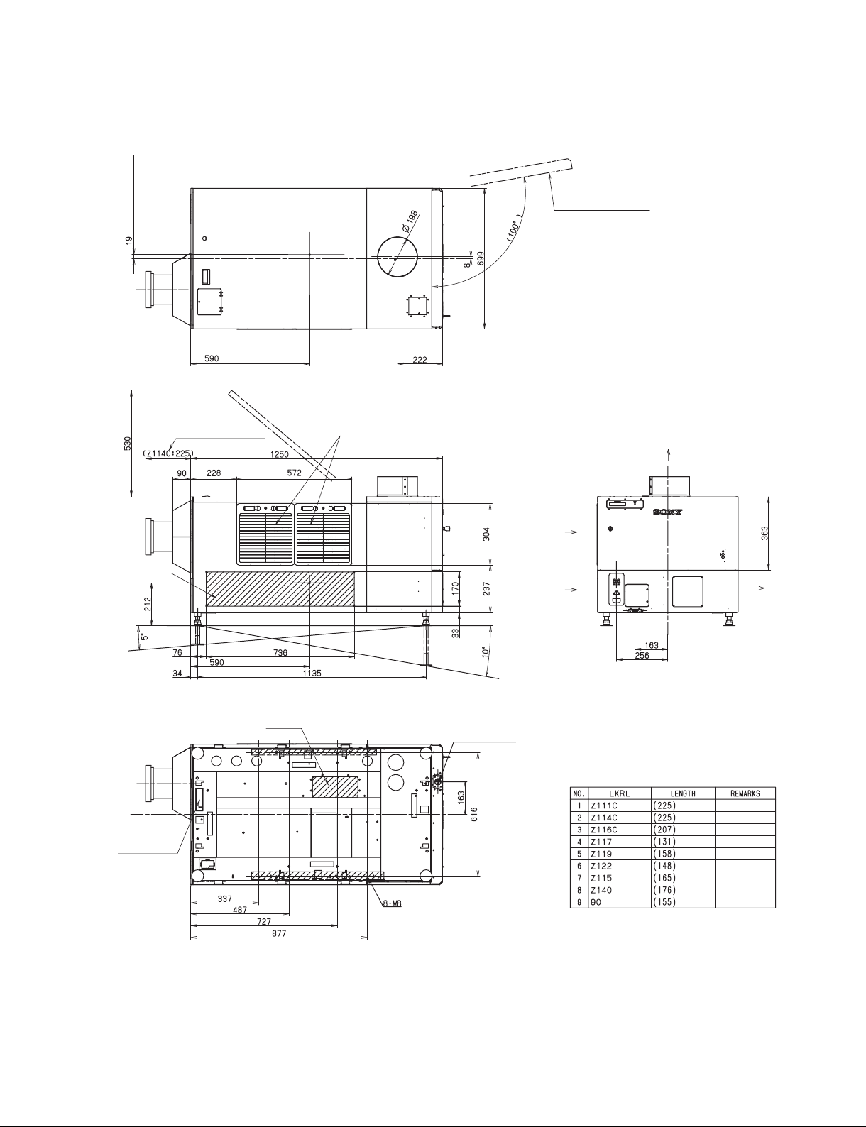
To p
(Barycentric position)
Right
Panel for lamp replacing
(Barycentric position)
Rear
Bottom
Intake
*
(Optional lens)
(Barycentric
position)
Refer to List
(Barycentric position)
Intake
Intake
AC power cable
Intake
Intake
*
LKRL LIST
Exhaust
Exhaust
Signal cable
SRX-T420
(For the unit fixing)
Unit: mm
1-33
Page 40

Page 41

Section 2
Adjustment
Adjustment is performed using an SRX Controller. Refer to Section 2-7. for how to use an SRX Controller.
Perform adjustment in the procedure below.
1. Install an SRX Controller in an adjusting personal computer.
(Refer to Operating Instructions.)
2. Perform the projector setting.
(Refer to Section 2-2.)
3. Perform the optical axis adjustment of a lamp.
(Refer to Section 2-3.)
4. Adjust a lens.
(Refer to Section 2-4.)
5. Perform illumination range adjustment and registration adjustment.
(Perform these adjustments as required.)
(Refer to Section 2-5.)
6. Perform the γ adjustment and uniformity adjustment using the PJ
COLOR ADJUSTMENT TOOL.
(Refer to Technical Manual of SRX-T110.)
7. Set the illuminance of a screen and perform color characteristic
correction (CSC adjustment).
(Refer to Section 2-6.)
SRX-T420
2-1
Page 42

2-1. Installation of SRX Controller
This unit can be operated the adjustments and setting using the supplied SRX Controller.
For about installation of SRX Controller, refer to Operating Instructions.
2-1-1. Startup
Connection
Connecting via the Ethernet
Shield case assembly (1)
NETWORK
connector
Ethernet cable
(cross cable)
(supplied)
PC
To Ethernet connector
Fig. 2-1-1a
n
Set the IP address of the connected computer to be assigned from DHCP.
Connecting via the RS-232C
To RS-232C connector
PC
RS-232C
cross cable
2-2
To RS-232C connector
Fig. 2-1-1b
SRX-T420
Page 43

Required equipment
. PC
- CPU: Intel Pentium M 1.6 GHz or more, and OS-recommended
- RAM capacity: 256 MB or more, 512 MB or more recommended, and OS-recommended
- Communication: LAN (10BASE-T/100BASE-T) or COM (RS-232C)
- Graphics mode: XGA (1024 x 768) or higher
- HDD: Built-in Drive, having an empty capacity of 15 MB or more
- CD-ROM drive: Eight times normal speed or faster
. OS: Microsoft Windows XP Professional SP2 (English or Japanese version, except for x64 Edition) or
Windows Vista Business (English or Japanese version)
. Ethernet cable (supplied with this unit) or RS-232C cross cable
Procedure
1. Connect this unit with PC.
2. Double-click the SRX Controller icon on the desktop of PC.
The program launcher window is displayed.
3. Double-click the projector name that you want to operate.
The control window is displayed.
Menu tab
Fig. 2-1-1c
4. Click the menu tab to display the window that you want to open.
5. If you want to display the SERVICE window or the SETTING window, type the password in the
password entering window and click the [OK] button.
Fig. 2-1-1d
Password (Initial setting)
. SERVICE window: service
. SETTING window: setting
n
Type the password using the lowercase characters.
SRX-T420
2-3
Page 44
2-1-2. Function Memory
You can register the settings that have been adjusted in the control windows to FUNCTION 1 to 7. As the
default setting, the settings are registered to FUNCTION 1. To register the settings to FUNCTION 2 to 7,
click one of the FUNCTION 2 to 7 radio buttons, then adjust the items in each window.
You can recall the desired setting by clicking one of the FUNCTION radio buttons.
n
When you click the FUNCTION button to switch to another FUNCTION setting, the picture will be cut
off for up to about 10 seconds. The picture with the selected FUNCTION setting will then appear on the
screen.
2-1-3. Log Function
If you select File → Save Log on the menu bar of the control window, the communication log between
SRX controller and this unit (from the startup of SRX Controller to that point of time) can be stored up to
5 MB.
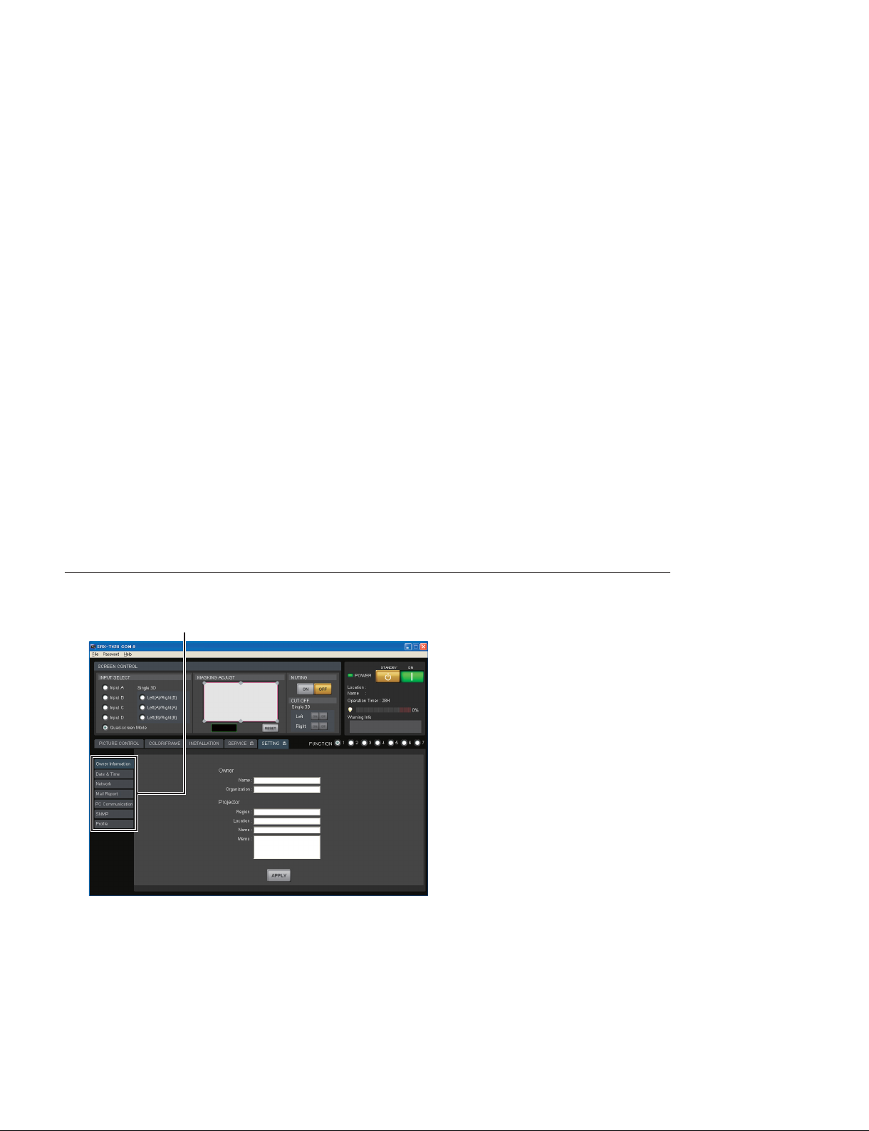
2-2. Setting of Projector
The status of this unit is set.
Operation procedure
Setting items
Fig. 2-2
1. Start SRX Controller and open the SETTING window. (Refer to Section 2-1-1.)
2. Click the setting item on the left side of the SETTING window to display the item that you want to
set.
3. After setting the items, click the [APPLY] button in the lower area of the window.
The setting is registered.
2-4
SRX-T420
Page 45

2-2-1. Owner Information
The information about this unit is set.
Fig. 2-2-1
Owner
Name: Type the name of owner.
Organization: Type the name of organization.
Projector
Region: Type the region that the unit is installed.
Location: Type the installation location.
Name: Type the arbitrary name.
Memo: Type memo.
SRX-T420
2-5
Page 46

2-2-2. Date & Time
The current time is set.
Fig. 2-2-2
Time Zone: Select the zone that the unit is installed.
Adjust clock for daylight saving changes: Place a check mark when adjusting clock for daylight saving.
Date & Time
Upper box: Click the button to display the calendar, and select the date.
Lower box: Click the hour or minute, and set the time using the button.
Time Server (NTP Server)
Address: Type the address of the network time server.
2-6
SRX-T420
Page 47

2-2-3. Network
The connection to the network is set.
Fig. 2-2-3
Internet Protocol (TCP/IP): Select either one of the following.
. Obtain an IP address automatically (DHCP): Obtains the IP address automatically from DHCP.
. Specify an IP address: Sets the specifi ed IP address.
When “Specify an IP address” is selected, perform the setting in the following boxes.
IP Address: Type the IP address.
Subnet Mask: Type the subnet mask.
Default Gateway: Type the default gateway.
Primary DNS: Type the IP address of primary DNS server.
Secondary DNS: Type the IP address of secondary DNS server.
LAN
MAC Address: Display the MAC address.
Speed: Select the Ethernet link speed.
SRX-T420
2-7
Page 48

2-2-4. Mail Report
The sending of mail for the lamp bulb operating time and the maintenance information is set.
Fig. 2-2-4
Reporting Timing
Lamp Timer Reminder: Set the lamp lighting-up time to send the lamp notifi cation mail.
Maintenance Reminder: Set the operating (power ON) time to send the maintenance notifi cation mail.
Re-count: Place a check mark to reset the operating (power ON) time of this unit after
the maintenance notifi cation mail is sent.
Reporting Source/Destination
FROM: Type the address of the mail sender.
Email Address: Type the address of the mail destination TO and CC.
Reporting Contents: Place a check mark in the reporting contents to be sent.
. Error: The error mail is sent.
. Lamp Timer/Maintenance: The lamp notifi cation mail and the maintenance notifi cation mail are
sent.
Mail Server
Outgoing Mail Server (SMTP): Type the server name or the IP address of SMTP (mail sending) server.
Requires Authentication: Place a check mark when the authentication is required to send the
mail. When you placed the check mark, select the following authentication method and perform the setting of authentication.
. POP before SMTP: Set the authentication of POP before SMTP.
- POP3 Server: Type the server name or the IP address of the POP3 server.
- Account Name: Type the login name of the POP3 server.
- Password: Type the password of the POP3 server.
. SMTP Authentication: Set the SMTP authentication.
- Account Name: Type the login name of the SMTP server.
- Password: Type the password of the SMTP server.
Send Test Mail: Place a check mark when sending the test mail.
2-8
SRX-T420
Page 49

2-2-5. PC Communication
The communication between this unit and PC is set.
Fig. 2-2-5
Projector Identifying: Setting of this unit
Port No: Type the UDP port number.
Interval: Select the packet transmission interval.
Broadcast Address: Type the broadcast address.
[>>] button: Add the address typed in Broadcast Address to the list.
[<<] button: Delete the address typed in Broadcast Address from the list.
(Registration list): Registration list of the broadcast address.
Controlling PC Destination: Setting of PC
Port No.: Type the TCP port number.
Time-out: Select the time of the communication time-out.
Accept connections from these hosts: Type the IP address of the host that you accept the access.
[>>] button: Add the typed IP address of the host to the list.
[<<] button: Delete the typed IP address of the host from the list.
(Registration list): Registration list of the IP address of the host that you accept the
access.
Network Block Reboot
[REBOOT] button: Click this button to reboot the network CPU.
n
After setting PC Communication, a reboot of the network CPU is required.
SRX-T420
2-9
Page 50

2-2-6. SNMP
SNMP (Simple Network Management Protocol) is set.
Fig. 2-2-6
SNMP
sysName: Type the character string of standard MIB sysName.
Contact: Type the character string of standard MIB sysContact.
Location: Type the character string of standard MIB sysDescr.
Send authentication trap: Place a check mark when accepting the sending of authentication trap.
Accept SNMP packets from any host: Select this when accepting the access from any host.
Accept SNMP packets from these hosts: Select this when accepting the access only from the specifi ed
host.
(Address): Type the IP address of the host that you accept the access.
[>>] button: Add the typed IP address of the host to the list.
[<<] button: Delete the typed IP address of the host from the list.
(Registration list): Registration list of the IP address of the host that you accept the access.
Community: Edit and select the community name.
. [Add] button: Add the community name.
. [Edit] button: Allow the selected community to enter the attribute edit mode.
. [Remove] button: Delete the selected community.
Community name: When the [Edit] button is clicked, the community whose attribute is changed
appears and the following items are enabled.
Rights: Select the access authority.
[Set|to|List]
[Cancel]
button: Attribute change is applied.
button: Attribute change is cancelled.
Trap Destinations: Type the IP address of the host of the trap destination.
[>>] button: Add the typed IP address of the host to the list.
[<<] button: Delete the typed IP address of the host from the list.
(Registration list): Registration list of the IP address of the host of the trap destination.
2-10
SRX-T420
Page 51

2-2-7. Profi le
The setting value of this unit is stored in PC, or the setting value stored in PC is written in this unit.
Fig. 2-2-7
Save: Place a check mark in the setting value to be stored in PC.
File: Edit and select the fi le name to be stored.
. [...] button: Select the fi le.
[SAVE] button: Store the checked setting value in the specifi ed fi le.
Load: Place a check mark in the setting value to be written in this unit from PC.
File: Edit and select the fi le name to be written.
. [...] button: Select the fi le to be written.
[LOAD] button: Write the checked setting value in this unit from the specifi ed fi le.
n
In the case that PC and this unit are connected by Ethernet, a part of setting value cannot be written and
its check box is disabled.
SRX-T420
2-11
Page 52

2-3. Optical Axis Adjustment of Lamp Bulb
[ON]
Procedure
1. Be sure to click the “SERVICE” tab in the standby state.
The SERVICE window is displayed.
“SERVICE” tab
“LAMP ADJUST & TIMER RESET” menu
Fig. 2-3a
button
2. Click the [SELECT] button in a “LAMP ADJUST & TIMER RESET” menu.
LAMP INFORMATION window is displayed.
Enter the serial code.
[CHECK] button
[START] button
Fig. 2-3b
3. Enter the serial code described in the Operating Instructions of a lamp bulb in the “Serial Code” box
[CLOSE] button
“LAMP ADJUST” menu
and click the [CHECK] button.
m
. Be sure to perform in the standby state.
. Enter the serial code with the space not put.
4. Click the [CLOSE] button and close the LAMP INFORMATION window.
5. Click the [ON] button of POWER.
2-12
SRX-T420
Page 53
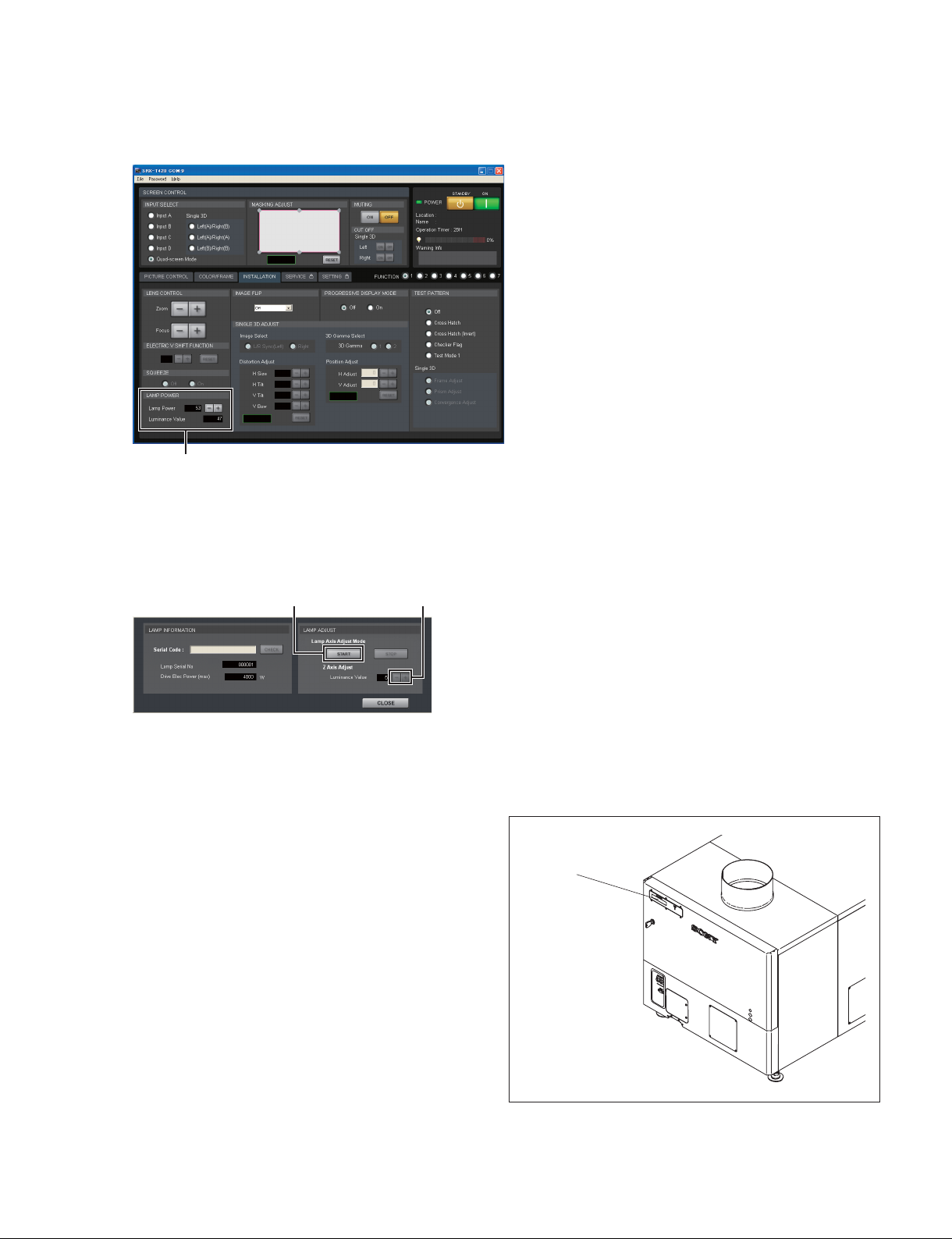
6. Click the “INSTALLATION” tab.
The INSTALLATION window is displayed.
“LAMP POWER” menu
Fig. 2-3c
7. Set the lamp power to 100% in the “LAMP POWER” menu to project an image in 100% black.
(No signal condition)
8. Display the LAMP INFORMATION window in the SERVICE window.
[START] button
[+], [_] buttons
Fig. 2-3d
9. Click the [START] button in a “Lamp Adjust” menu.
The unit enters the lamp adjustment mode.
10. Wait for fi ve minutes.
11. When the unit enters the lamp adjustment mode, the
value of the internal luminance sensor is displayed on
the status message display.
Adjust “Z Axis Adjust” using the [+]/[_] button so
that the luminance value becomes maximum.
Status message
display
Fig. 2-3e
SRX-T420
2-13
Page 54

12. In the same way, adjust the X-axis and Y-axis direction
adjusting screws so that the value of the internal luminance sensor becomes maximum.
13. Adjust “Z Axis Adjust” again using the [+]/[_] button
so that the value of the internal luminance sensor
becomes maximum.
X-axis direction
adjusting screw
Y-axis direction
adjusting screw
Fig. 2-3f
2-14
SRX-T420
Page 55

2-4. Lens Adjustment (H Shift, V Shift, Zoom, and Focus)
Procedure
1. Project a test pattern on the INSTALLATION window.
2. Loosen the four bolts securing the projection lens.
Insert the fl at screwdriver between the lens bracket and
the lens bracket shield and move the projection lens
from side to side to adjust the horizontal position (H
shift) of the image.
3. After H shift adjustment is completed, tighten the four
screws loosened in step 2.
Tighten the bolts in the order of to .
Projection
lens
Bolts
Projection lens
Lens bracket
Lens bracket
shield
Flat screwdriver
4. Open the adjustment lid.
5. Turn the control knob of this unit to move the lens up
and down for adjusting the vertical position (V shift)
of an image.
6. Adjust the zoom and focus using the [+] and [_]
buttons in the “LENS CONTROL” menu.
(Refer to “2-7-2. INSTALLATION Window”.)
Bolts
Fig. 2-4a
Control knob
Projection lens
Adjustment lid
SRX-T420
Fig. 2-4b
2-15
Page 56

n
Set the V shift amount within 1/2 screen. If it exceeds 1/2 screen, the zoom is changed, the image position
may not be positioned at same place.
Check if the V shift amount exceeds 1/2 screen in the following procedure.
When the V shift amount exceeds 1/2 screen, perform the adjustment.
In the case that the V shift is lowered.
How to Check
. When the image is expanded by zoom, the upper end of image position is lowered.
Effective area of lens
Effective area of lens
Center of lens
Image
Image
Fig. 2-4c
How to Adjust
. Adjust the V shift so that the upper end of image position remains unchanged when the image is expand-
ed by zoom.
Effective area of lens
Effective area of lens
Center of lens
Image
Image
Fig. 2-4d
2-16
SRX-T420
Page 57

2-5. Illumination Area Adjustment and Registration Adjustment
2-5-1. Illumination Area Adjustment
If there is any deviation of illumination range when installing the unit, perform adjustment in the following procedure.
n
The adjustment cannot be correctly performed with the fi lter cover open because the fi lter cover switch
sensor function operates. Before starting the adjustment, be sure to close the fi lter cover after removing
the panel duct covers.
Front side
Filter cover
Filter cover switch
Fig. 2-5-1a
Procedure
1. Remove the panel (U7) block assembly. (Refer to Section 1-1-2.)
2. Remove the panel (U2) block assembly. (Refer to Section 1-1-3.)
3. Remove the fi lter.
4. Remove the fi ve screws.
Filter (center portion)
SRX-T420
Front side
Fig. 2-5-1b
Screws
2-17
Page 58

5. Open the panel duct in the direction of the arrow.
6. Remove the two screws, then remove the panel duct cover (upper).
7. Remove the two screws, then remove the panel duct cover (lower).
8. Close the fi lter cover, then secure it with the screw.
Front side
Filter cover
Panel duct cover (upper)
Screws
Panel duct cover (lower)
Filter cover
Screws
Secure with the screw.
Fig. 2-5-1c
2-18
SRX-T420
Page 59

9. Set Lamp Power to 53% in the “LAMP POWER”
menu on the INSTALLATION window of SRX Controller immediately after the lamp is lit.
10. Project the white image on the screen using “Test
Mode 1” in the “TEST PATTERN” menu.
n
If it is diffi cult to observe the left, right, top and bot-
tom edges of the white image because it is interrupted
by the black curtain and so on, reduce the white image
size using the zoom so that its edges can be viewed
clearly. Adjust the zoom in “LENS CONTROL”. In the
case of out-of- focus, adjust it in the same way.
(Refer to “2-7-2. INSTALLATION Window”.)
11. Perform steps 12 to 14 immediately after step 10 is
fi nished.
12. Observe the left, right, top and bottom edges of the
screen precisely.
13. Check the deviation of illumination range (colored area
around the white image). If there is an area colored by
cyan, loosen the adjusting plate fi xing screws of por-
tion A in the illustration, and tighten them after adjustment.
14. If there is an area colored by magenta/yellow, loosen
the adjusting plate fi xing screws of portion B in the
illustration, and tighten them after adjustment.
Portion A
Adjusts the left and right of the white image by
parallel movement.
Adjusts the top and bottom of the white image by
rotational movement.
Portion B
2-5-2. Registration Adjustment
Perform adjustment referring to “2-7-3. SERVICE Window” if registration is displaced.
Fig. 2-5-1d
SRX-T420
2-19
Page 60

2-6. Color Space Conversion (CSC Adjustment)
The color space of this unit can be corrected for each color reproduction range.
n
The CSC adjustment cannot be correctly performed if γ is displaced.
It is recommended to perform the γ adjustment and the uniformity adjustment fi rst.
(Refer to SRX-T110 Technical Manual.)
2-6-1. Correcting the Color Space “sRGB (709)” or “Adobe RGB”
Procedure
1. Display the SERVICE window of SRX Controller.
“COLOR SPACE CONVERTER” menu
Fig. 2-6-1
2. Select “sRGB (709)” or “Adobe RGB” in Color Space of the “COLOR SPACE CONVERTER”
menu.
n
To select Color Space, it is required to input the video signal.
3. Click the [RESET] button.
4. Click the [APPLY] button.
The color space function becomes OFF, and then the characteristics of this unit can be measured.
5. Connect PC for projection, and then project the 80% white signal.
6. Measure the value of x and y at the center of screen using the color meter.
7. Enter the measured value of x and y in the W box of “Projector Color Gamut”.
8. Project the 80% red signal, 80% green signal and 80% blue signal respectively from PC for projection, and then measure the value of x and y at the center of screen.
9. Enter the value measured in step 8 in the R, G, and B boxes of “Projector Color Gamut” respectively.
10. Click the [CALC] button.
11. Project the 80% red signal, 80% green signal and 80% blue signal respectively, and then measure the
value of x and y at the center of screen again.
2-20
SRX-T420
Page 61

12. Check that the difference between the value measured in step 11 and the “Target Color Gamut” value
is within the following margin of error.
80% green signal when Adobe RGB is selected: within ?0.010
Other than the above: within ?0.005
n
If the difference is not within the margin of error, repeat steps 5 to 11.
13. Click the [APPLY] button.
2-6-2. Correcting the Color Space “DCDM”
Procedure
1. Display the SERVICE window of SRX Controller.
“COLOR SPACE CONVERTER” menu
Fig. 2-6-2
2. Select “DCDM” in Color Space of the “COLOR SPACE CONVERTER” menu.
n
To select Color Space, it is required to input the video signal.
3. Click the [RESET] button.
4. Click the [APPLY] button.
The color space function becomes OFF, and then the characteristics of this unit can be measured.
5. Select “Gray10” in “Test Pattern Select”.
The test pattern of Gray 10 is projected.
6. Measure the value of x and y at the center of screen using the color meter.
7. Enter the measured value of x and y in the W box of “Projector Color Gamut”.
8. Project “Red1”, “Green1” and “Blue1” in “Test Pattern Select” respectively, and then measure the
value of x and y at the center of screen.
9. Enter the value measured in step 8 in the R, G, and B boxes of “Projector Color Gamut” respectively.
10. Click the [CALC] button.
11. Project “Gray 10”, “Red1”, “Green1” and “Blue1” respectively, and then measure the value of x and
y at the center of screen again.
SRX-T420
2-21
Page 62
12. Check that the difference between the value measured in step 11 and the “Target Color Gamut” value
is within the margin of error ?0.005.
n
If the difference is not within the margin of error, repeat steps 5 to 11.
13. Click the [APPLY] button.
2-7. Functions of Each Window
This section describes the functions of SRX Controller required for the installation.
For about the PICTURE CONTROL window and COLOR/FRAME window, refer to the Operating
Instructions.
2-7-1. Common Items
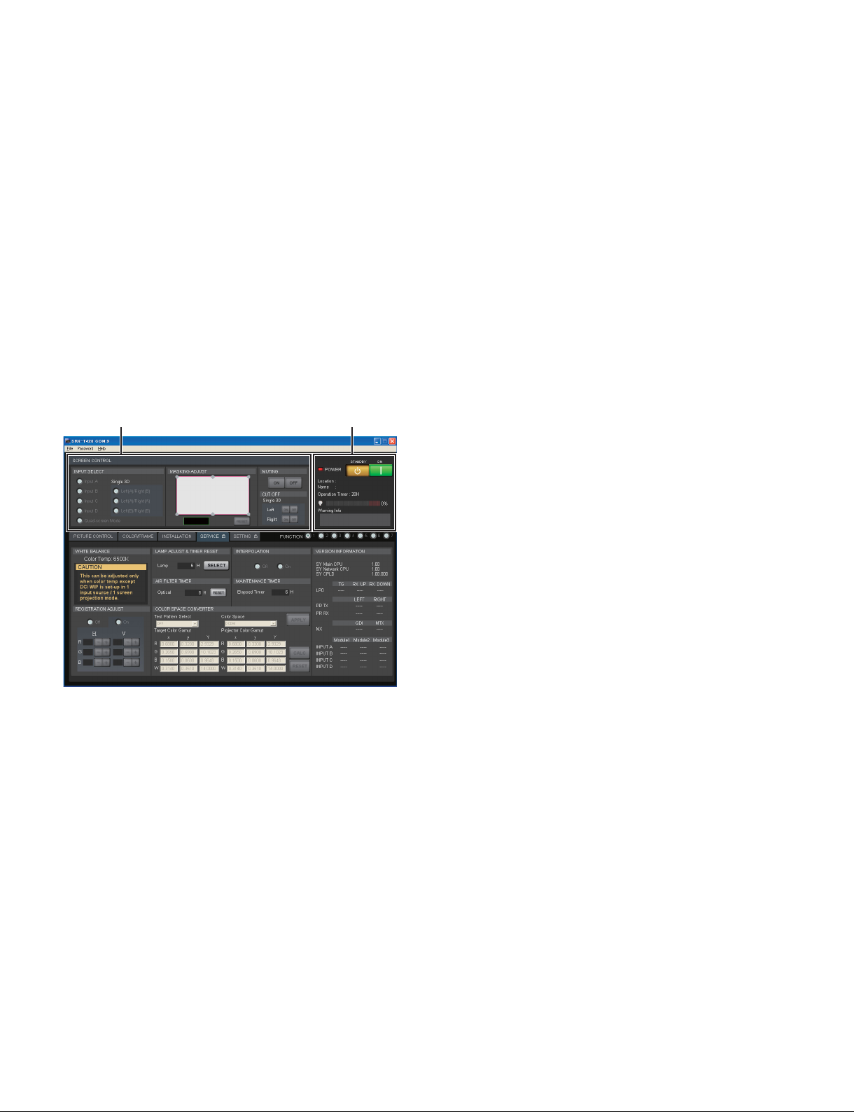
Fig. 2-7-1a
SCREEN CONTROL
POWER/Location/Name/Operation Timer/Warning Info
SCREEN CONTROL
. INPUT SELECT
Selects the input signal to be output as video signal.
- Input A: Displays the signal from DVI board (default) or optional board.
- Input B to D: Displays the signal from optional board.
- Quad-screen Mode: Displays the four signals from Input A to D in a quad-screen.
- Single 3D: This item is for 3D lens. For detail, refer to the Installation and Service Manual
of LKRL-A002/A003.
2-22
SRX-T420
Page 63
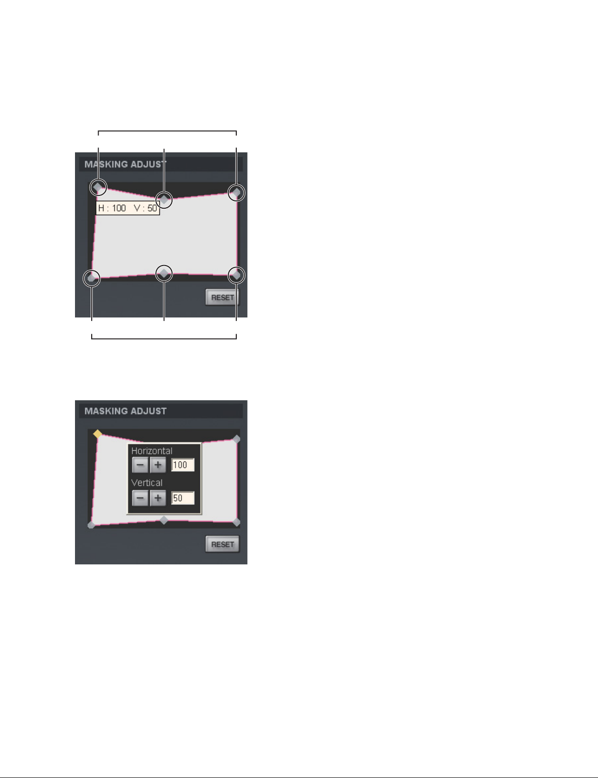
. MASKING ADJUST
Adjusts the image masking according to the screen shape by the six adjusting point respectively. And
adjustment value is displayed by pointing the cursor at each adjusting point.
Adjusting points
Adjusting points
Fig. 2-7-1b
When an adjusting point is double-clicked, the adjustment window is displayed.
Fig. 2-7-1c
A setting value increases when you click the [+] button. A numeric value decreases when you click the
[_] button. The numeric value can also be entered directly.
Each setting value is as follows:
to : 0 to 950
, : _500 to 500
n
After the adjusting of adjusting point to is completed, perform the adjusting of adjusting point
and .
All items in a MASKING ADJUST menu are returned to the factory setting when you click the [RESET]
button.
SRX-T420
2-23
Page 64

. MUTING
Operates to close and open of the douser.
- [ON] button: Close the douser. (Muting condition)
- [OFF] button: Open the douser.
. CUT OFF
When a 3D lens is attached, switch the output of L image and R image.
For detail, refer to the Installation and Service Manual of LKRL-A002/A003.
POWER/Location/Name/Operation Timer/Warning Info
. POWER
- STANDBY: Puts this unit into the standby state. (Canceled using an [ON] button.)
- ON: Turns on the power.
. Location: Displays the location.
. Name: Displays the owner name.
. Operation Timer: Displays the total operation time of this unit.
.
(Lamp bulb): Indicates the proportion of elapsed usage time (%) to the recommended time between
replacements. Indicates in red as the recommended time approaches.
. Warning Info: Displays warning information.
2-7-2. INSTALLATION Window
LENS CONTROL
LAMP POWER
TEST PATTERN
SINGLE 3D ADJUST
Fig. 2-7-2
2-24
SRX-T420
Page 65

LENS CONTROL
Adjusts the image projected on the screen.
. Zoom: Adjusts the size of an image. An image is expanded when you click the [+] button. It is
reduced when you click the [_] button.
. Focus: Adjusts a focus. A focus is adjusted to the distance place when you click the [+] button. It is
adjusted to the nearby place when you click the [_] button.
LAMP POWER
. Lamp Power: Can adjust the output of a light source lamp bulb in units of 1% between 53% and
100%. The screen becomes dark when a numeric value decreases. In this case,
however, the power consumption decreases and the life of a lamp bulb becomes
long. Clicking the [+] button, the numeric value increases. Clicking the [_] button,
the numeric value decreases.
. Luminance Value: For axis adjustment after the lamp bulb is replaced.
TEST PATTERN
An image can be adjusted by projecting the test pattern, built in this unit, on the screen without inputting
the signal from other equipment.
Each test pattern is as follows:
. Off: No test pattern
. Cross Hatch
. Cross Hatch (Invert)
. Checker Flag
. Test Mode 1
. Single 3D
The test patterns in Single 3D column are for 3D lens. For detail, refer to the Installation and Service
Manual of LKRL-A002/A003.
SINGLE 3D ADJUST
This item is for 3D lens. For detail, refer to the Installation and Service Manual of LKRL-A002/A003.
SRX-T420
2-25
Page 66

2-7-3. SERVICE Window
Fig. 2-7-3a
WHITE BALANCE
REGISTRATION ADJUST
LAMP ADJUST & TIMER RESET
AIR FILTER TIMER
INTERPOLATION
MAINTENANCE TIMER
COLOR SPACE CONVERTER
VERSION INFORMATION
WHITE BALANCE
The adjustments of Gain R/G/B and Bias R/G/B are performed and the color temperature is set. It is used
to adjust the subtle difference of color among the projectors when more than one projector is used. When
adjusting only one projector, use Color Space Converter. (Refer to Section 2-6.)
m
. WHITE BALANCE can be adjusted only in the full-screen mode.
. The value adjusted here is refl ected only on “Color Temp” of the input signal currently selected.
Adjustment when more than one projector is used
1. Perform the CSC adjustment for all projectors. (Refer to Section 2-6.)
2. Project the 80% white signal.
3. Select the projector as a reference and adjust the Gain value of other projectors to the Gain value of
the reference projector.
2-26
SRX-T420
Page 67
REGISTRATION ADJUST
Moves R (red), G (green), and B (blue) in the horizontal and vertical directions by two pixels (maximum)
one pixel at a time so as to adjust registration.
. On: Selects when adjusting.
. Off: Selects when not adjusting.
. H: Pixels move in the horizontal direction.
R: Red pixels horizontally move by two pixels (maximum) one pixel at a time when you click the
[+]/[_] button.
G: Green pixels horizontally move by two pixels (maximum) one pixel at a time when you click the
[+]/[_] button.
B: Blue pixels horizontally move by two pixels (maximum) one pixel at a time when you click the
[+]/[_] button.
. V: Pixels moves in the vertical direction.
R: Red pixels vertically moves by two pixels (maximum) one pixel at a time when you click the
[+]/[_] button.
G: Green pixels vertically moves by two pixels (maximum) one pixel at a time when you click the
[+]/[_] button.
B: Blue pixels vertically moves by two pixels (maximum) one pixel at a time when you click the
[+]/[_] button.
LAMP ADJUST & TIMER RESET
Displays the operation time of a lamp bulb and resets the LAMP TIMER.
. Lamp: Displays the operation time of a lamp bulb.
. [SELECT] button: Clicking the button, displays the LAMP INFORMATION window.
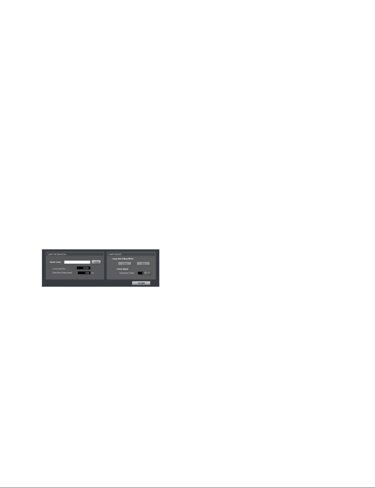
Fig. 2-7-3b
LAMP INFORMATION
. Serial Code: Enter the serial number of a lamp bulb.
. [CHECK] button: Clicking the button with the Serial Code box entered, resets LAMP TIMER.
- Lamp Serial No.: Displays the serial code of a lamp bulb.
- Drive Elec Power (max): Displays maximum driving power.
LAMP ADJUST
. Lamp Axis Adjust Mode
Switches the axis adjust mode of the lamp bulb.
- [START] button: Enables the axis adjustment.
- [STOP] button: Quits the axis adjustment.
. Z Axis Adjust
- Luminance Value: Displays the value of the internal luminance meter.
AIR FILTER TIMER
Displays and resets the operation time of air fi lter.
. Optical: Displays the operation time of the air fi lter on the panel duct.
. [RESET] button: Clicking the button, resets AIR FILTER TIMER.
SRX-T420
2-27
Page 68

INTERPOLATION
Switches the interpolation function during the projection of 2K-resolution image.
. On: Projects the high-resolution picture quality with a smooth image.
. Off: Projects the pixelated rough image.
MAINTENANCE TIMER
. Elapsed Timer
Displays the cumulative lighting time of lamp valve. (excluding cooling time)
n
Other timer: Operation timer displays the cumulative operation time of the unit.
COLOR SPACE CONVERTER
Adjusts the CSC. (Refer to Section 2-6.)
VERSION INFORMATION
Displays the version of this unit.
2-7-4. SETTING Window
Fig. 2-7-4
Sets the various settings of the projector. (Refer to Section 2-2.)
2-28
SRX-T420
Page 69

Section 3
Error Message
The following messages are displayed in the status message display at the back of the main unit and the
“Warning Info” of an SRX controller.
These messages are classifi ed into ALERT (degree of risk: high), WARNING (degree of risk: middle), and
FAILURE (degree of risk: low) according to the degree of risk.
Take proper measures according to the message number and the remedy.
n
For WARNING (degree of risk: middle) and FAILURE (degree of risk: low), the power is not automatically turned off during operation of the main unit (during projection). However, take proper measures
according to the remedy when the power is turned off next.
SRX-T420
3-1
Page 70

ALERT (Degree of risk: high)
Message No. Error message Trouble Remedy
ALERT_01 BOARD ERROR The power of IFA board is defective. Check the IFA board. Replace the IFA
board if it is damaged.
ALERT_02 BOARD ERROR The power of IFB board is defective. Check the IFB board. Replace the IFB
board if it is damaged.
ALERT_03 BOARD ERROR The power of IFC board is defective. Check the IFC board. Replace the IFC
board if it is damaged.
ALERT_04 BOARD ERROR The power of IFD board is defective. Check the IFD board. Replace the IFD
board if it is damaged.
ALERT_05 BOARD ERROR The power of the MX board is defective. Check the MX board. Replace the MX
board if it is damaged.
ALERT_06 BOARD ERROR The power of the LPD board is defective. Check the LPD board. Replace the LPD
board if it is damaged.
ALERT_07 BOARD ERROR The power of the CT board is defective. Check the CT board. Replace the CT
board if it is damaged.
ALERT_08 BOARD ERROR The power of the DST board is defective. Check the DST board. Replace the DST
board if it is damaged.
ALERT_09 BOARD ERROR The power of the PR1 board is defective. Check the PR1 board. Replace the PR1
board if it is damaged.
ALERT_10 BOARD ERROR The power of the PR2 board is defective. Check the PR2 board. Replace the PR2
board if it is damaged.
ALERT_11 BOARD ERROR The power of the SY board is defective. Check the SY board. Replace the SY
board if it is damaged.
ALERT_12 BOARD DETACHED The CN board is disconnected. Check the CN board.
ALERT_13 BOARD DETACHED The MX board is disconnected. Check the MX board.
ALERT_14 BOARD DETACHED The LPD board is disconnected. Check the LPD board.
ALERT_15 BOARD DETACHED The CT board is disconnected. Check the CT board.
ALERT_16 BOARD DETACHED The DST board is disconnected. Check the DST board.
ALERT_17 BOARD DETACHED The PR1 board is disconnected. Check the PR1 board.
ALERT_18 BOARD DETACHED The PR2 board is disconnected. Check the PR2 board.
ALERT_19 TEMPERATURE ERROR The unit stops operation by temperature
abnormality of the R panel.
ALERT_20 TEMPERATURE ERROR The unit stops operation by temperature
abnormality of the G panel.
ALERT_21 TEMPERATURE ERROR The unit stops operation by temperature
abnormality of the B panel.
ALERT_22 COVER DETACHED The rear cabinet is detached and/or the
cold mirror is out of position.
ALERT_27 FAN ERROR The lamp fan A is defective. Check the lamp fan A. Replace the fan if
ALERT_28 FAN ERROR The lamp fan B is defective. Check the lamp fan B. Replace the fan if
ALERT_29 FAN ERROR The lamp fan C is defective. Check the lamp fan C. Replace the fan if
ALERT_30 FAN ERROR The lamp fan D is defective. Check the lamp fan D. Replace the fan if
ALERT_32 BALLAST ERROR The unit stops operation by temperature
abnormality of the power unit for lamp.
Check the outside air temperature, and air
supply and exhaust. Check the Peltier R.
Replace the Peltier R if it is damaged.
Check the outside air temperature, and air
supply and exhaust. Check the Peltier G.
Replace the Peltier G if it is damaged.
Check the outside air temperature, and air
supply and exhaust. Check the Peltier B.
Replace the Peltier B if it is damaged.
Check the panel (U4) block assembly and
cold mirror position.
it is damaged.
it is damaged.
it is damaged.
it is damaged.
Check the outside air temperature, air
supply and exhaust, and power unit for
lamp. Replace the power unit for lamp if it
is damaged.
(Continued)
3-2
SRX-T420
Page 71

Message No. Error message Trouble Remedy
ALERT_33 BALLAST ERROR The power unit for lamp fan is abnormal. Check the power unit for lamp fan. Re-
place the fan if it is damaged.
ALERT_34 BALLAST ERROR The power unit for lamp is abnormal. Check the cable between the power unit
for lamp and lamp house. Check the
power unit for lamp. Replace the power
unit for lamp if it is damaged.
ALERT_35 LAMP ERROR The lamp goes off. Check the lamp. Replace lamp bulb if it is
damaged. Check the power unit for lamp.
Replace the power unit for lamp if it is
damaged.
ALERT_36 BALLAST ERROR The power unit for lamp is abnormal. Check the cable between the power unit
for lamp and lamp house. Check the
power unit for lamp. Replace the power
unit for lamp if it is damaged.
ALERT_37 COVER DETACHED The maintenance cover assembly is out of
position.
ALERT_38 BOARD ERROR The power of the CN board is defective. Check the CN board. Replace the board if
ALERT_39 TEMPERATURE ERROR The unit stops operation by temperature
abnormality of the 8-inch duct block.
ALERT_41 COVER DETACHED The unit stops operation by the fi lter cover
detaching.
Check the maintenance cover assembly.
it is damaged.
Check the outside air temperature, the
suction amount of a 8-inch duct, and the
lamp fans A to D.
Check that the fi lter cover (door) is not
open.
WARNING (Degree of risk: middle)
Message No. Error message Trouble Remedy
WARN_01 FAN ERROR The power fan 1 is abnormal. Check the power fan 1. Replace the
power fan 1 if it is damaged.
WARN_02 FAN ERROR The power fan 2 is abnormal. Check the power fan 2. Replace the
power fan 2 if it is damaged.
WARN_05 FAN ERROR The board fan 1 is abnormal. Check the board fan 1. Replace the board
fan 1 if it is damaged.
WARN_06 FAN ERROR The board fan 2 is abnormal. Check the board fan 2. Replace the board
fan 2 if it is damaged.
WARN_12 FAN ERROR The Peltier R fan is abnormal. Check the Peltier R fan. Replace the
Peltier R fan if it is damaged.
WARN_13 FAN ERROR The Peltier G fan is abnormal. Check the Peltier G fan. Replace the
Peltier G fan if it is damaged.
WARN_14 FAN ERROR The Peltier B fan is abnormal. Check the Peltier B fan. Replace the
Peltier B fan if it is damaged.
WARN_20 DEVICE ERROR The Peltier R is out of control. Check the outside air temperature, and air
supply and exhaust. Check the Peltier R.
Replace the Peltier R if it is damaged.
WARN_21 DEVICE ERROR The Peltier G is out of control. Check the outside air temperature, and air
supply and exhaust. Check the Peltier G.
Replace the Peltier G if it is damaged.
WARN_22 DEVICE ERROR The Peltier B is out of control. Check the outside air temperature, and air
supply and exhaust. Check the Peltier B.
Replace the Peltier B if it is damaged.
WARN_23 CONNECTOR DE-
TACHED
WARN_24 CONNECTOR DE-
TACHED
WARN_25 CONNECTOR DE-
TACHED
SRX-T420
The connector of a Peltier R is disconnected.
The connector of a Peltier G is disconnected.
The connector of a Peltier B is disconnected.
Check the connector of a Peltier R.
Check the connector of a Peltier G.
Check the connector of a Peltier B.
(Continued)
3-3
Page 72

Message No. Error message Trouble Remedy
WARN_26 DOUSER ERROR DOUSER operation is failed. Check the connector of a shift block.
WARN_27 BALLAST ERROR A power unit for lamp communication
failed.
WARN_28 BALLAST ERROR Lamp serial number setting is wrong. Check the range setting of power unit for
WARN_30 COVER DETACHED The fi lter cover is detached. Check that the fi lter cover (door) is not
WARN_31 FAN ERROR PS converter fan 2 in abnormal. Check the PS converter fan 2. Replace
WARN_32 FAN ERROR PS converter fan 1 in abnormal. Check the PS converter fan 1. Replace
WARN_33 FAN ERROR PBS fan in abnormal. Check the PBS fan. Replace the PBS fan
Check the shift block. Replace the shift
block if it is damaged.
Check the cable between the power unit
for lamp and lamp house. Check the
power unit for lamp. Replace the power
unit for lamp if it is damaged.
lamp and the serial information of a lamp.
opened.
the PS converter fan 2 if it is damaged.
the PS converter fan 1 if it is damaged.
if it is damaged.
FAILURE (Degree of risk: low)
Message No. Error message Trouble Remedy
FAIL_02 TEMPERATURE ERROR Warning for temperature abnormality of
the 8-inch duct.
FAIL_04 TEMPERATURE ERROR Intake temperature is abnormal. Check the outside air temperature.
FAIL_06 TEMPERATURE ERROR The optical unit block temperature is
abnormal.
FAIL_10 TEMPERATURE ERROR Warning for temperature abnormality of
the R panel.
FAIL_11 TEMPERATURE ERROR Warning for temperature abnormality of
the G panel.
FAIL_12 TEMPERATURE ERROR Warning for temperature abnormality of
the B panel.
FAIL_15 TEMPERATURE ERROR Warning for temperature abnormality of
the power unit for lamp.
FAIL_16 LENS ERROR Zoom does not reach the registered
position.
FAIL_17 LENS ERROR Focus does not reach the registered
position.
FAIL_18 LENS ERROR Zoom operation is failed. Check the lens and lens cable. Check the
Check the outside air temperature, the
suction amount of a 8-inch duct, and the
lamp cooling fans.
Check the outside air temperature, and air
supply and exhaust.
Check the outside air temperature, and air
supply and exhaust. Check the Peltier R.
Replace the Peltier R if it is damaged.
Check the outside air temperature, and air
supply and exhaust. Check the Peltier G.
Replace the Peltier G if it is damaged.
Check the outside air temperature, and air
supply and exhaust. Check the Peltier B.
Replace the Peltier B if it is damaged.
Check the outside air temperature. Check
the power unit for lamp. Replace the
power unit for lamp if it is damaged.
Check the function operation, lens, and
lens cable. Check the SY board. Replace
the SY board if it is damaged.
Check the function operation, lens, and
lens cable. Check the SY board. Replace
the SY board if it is damaged.
SY board. Replace the SY board if it is
damaged.
3-4
(Continued)
SRX-T420
Page 73

Message No. Error message Trouble Remedy
FAIL_19 LENS ERROR Focus operation is failed. Check the lens and lens cable. Check the
SY board. Replace the SY board if it is
damaged.
FAIL_21 ADJUSTMENT ERROR The Z-axis operation is failed. Check the lamp house-supplied motor and
harness. Replace the motor if it is damaged. Check the SY board. Replace the
SY board if it is damaged.
FAIL_25 DEVICE ERROR FPGA confi guration fails. Turn off the power once, then turn on it
again.
FAIL_26 DEVICE ERROR I
2
C communication error. Turn off the power once, then turn on it
again.
FAIL_27 DEVICE ERROR LVDS error Turn off the power once, then turn on it
again.
FAIL_28 DEVICE ERROR PLL error Turn off the power once, then turn on it
again.
FAIL_29 DEVICE ERROR Parity error Turn off the power once, then turn on it
again.
FAIL_30 BALLAST ERROR The power unit for lamp is interlocked. Turn off the power once, then turn on it
again.
FAIL_36 DEVICE ERROR Setting error of DVI. Check the setting and set the operation
again.
SRX-T420
3-5
Page 74

n
Fan location
CN board
7 Front side
Front side
Top view
PS converter
fan 2
Lamp fan A
Lamp fan B
Lamp fan C
Lamp fan D
DST
board
Peltier R fan
Filter cover
PS converter fan 1
Peltier G fan
Peltier B fan
PBS fan
3-6
SRX-T420
Page 75

Page 76

SRX-T420 (SY) E
9-968-662-01
Sony Corporation
Printed in Japan
2009. 10 22
©2009
 Loading...