

Page 1
Data Projector
4-115-586-11 (2)
Installation Manual for Dealers
WARNING
This manual is intended for qualified service personnel only.
To reduce the risk of electric shock, fire or injury, do not perform any servicing other
than that contained in the operating instructions unless you are qualified to do so.
Refer all servicing to qualified service personnel.
SRX-T110
SRX-T105
© 2008 Sony Corporation
Page 2

Table of Contents
Chapter 1 Overview
Precautions ......................................................................................4
About the Optional Accessories ....................................................5
Chapter 2 Installation and Connections
About the Display Mode..................................................................6
Projection Distance Charts.............................................................7
Before Installation .........................................................................11
About the Mounting Platform ............................................................. 11
Positioning the Projector towards the Screen...................................... 11
Installing Lamp Houses ................................................................12
Attaching the Lens ........................................................................12
Using the Optional Input Board....................................................14
Attaching the Exhaust Duct Adaptor ...........................................15
Connecting the Projector..............................................................16
Connecting a Computer Equipped with a DVI-D Connector.............. 16
Connecting with a Computer Equipped with an Analog RGB
Connector................................................................................... 17
Connecting with HD-SDI Equipment ................................................. 17
Connecting with Component/Video GBR Equipment ........................ 18
Connecting the AC Power Cord ...................................................18
Installing the SRX Controller ........................................................19
Setting the Projector .....................................................................20
Displaying the SETTING Window ..................................................... 20
Owner Information .............................................................................. 20
Date & Time........................................................................................ 20
Network ............................................................................................... 21
Mail Report.......................................................................................... 21
PC Communication ............................................................................. 22
SNMP .................................................................................................. 22
Profile .................................................................................................. 23
Chapter 3 Adjustments and Settings Using the SRX Controller
Displaying the Control Function Menu Window .........................24
PICTURE CONTROL Window .......................................................25
2
Table of Contents
Page 3

Board ................................................................................................... 25
Input Source ........................................................................................ 25
Signal Info (Information) .................................................................... 26
Signal Adjust ....................................................................................... 26
COLOR/FRAME Window ...............................................................27
Board ................................................................................................... 27
Color.................................................................................................... 27
Frame Adjust ....................................................................................... 28
INSTALLATION Window................................................................28
LENS CONTROL ............................................................................... 28
ELECTRIC V SHIFT FUNCTION..................................................... 28
SIRCS.................................................................................................. 29
IMAGE FLIP....................................................................................... 29
PROGRESSIVE DISPLAY MODE ................................................... 29
SQUEEZE ........................................................................................... 29
LAMP POWER................................................................................... 29
LAMP SELECT .................................................................................. 29
TEST PATTERN ................................................................................ 30
SERVICE Window ..........................................................................30
Displaying the SERVICE Window ..................................................... 30
WHITE BALANCE ............................................................................ 30
REGISTRATION ADJUST ................................................................ 31
LAMP TIMER RESET ....................................................................... 31
INTERPOLATION ............................................................................. 31
COLOR SPACE CONVERTER ......................................................... 31
VERSION INFORMATION............................................................... 31
Correcting the Color Characteristics (Color Space Converter) 32
Input Signals And Adjustable/Setting Items ...............................34
Chapter 4 Others
Lamp Life........................................................................................35
Error Messages..............................................................................36
Dimensions ....................................................................................38
External Dimensions ........................................................................... 38
Mounting Platform Dimensions .......................................................... 39
Necessary Clearance for Installation and Maintenance ...................... 41
Displayed Image Size in Multiple Screen Mode ..........................42
Index ...............................................................................................43
Table of Contents
3
Page 4

Chapter 1 Overview
Overview
Precautions
On safety
• Operate the unit on 200 – 240 V AC, 50/60 Hz (SRXT110), or 100 – 240 V AC, 50/60 Hz (SRX-T105).
• Should any liquid or solid object fall into the cabinet,
unplug the unit and have it checked by Sony dealer
before operating it further.
• Unplug the unit from the wall outlet or set the power
switch to the lower position if it is not to be used for
several days.
• To disconnect the cord, pull it out by the plug. Never pull
the cord itself.
• The wall outlet should be near the unit and easily
accessible.
• The unit is not disconnected from the AC power source
(mains) as long as it is connected to the wall outlet and
the power switch is set to the upper position.
• Do not look into the lens while the lamp is on.
• Do not place your hand or objects near the ventilation
holes. The air coming out is hot.
• Have at least four people carry and handle the projector,
to avoid accidents or injury.
• Avoid using an extension cord with a low voltage limit,
as it may cause short-circuiting and physical injury.
• To carry the projector, be sure to use the carrying
handles. Do not hold other parts of the projector,
especially the lens, nor catch your finger between the
handle, floor, and the projector.
• Do not catch your finger between the unit and surface of
the floor when moving the projector installed on the
floor.
• Be careful not to catch your finger in the cooling fan.
• Since an intense light has come out of this projector from
the front, do not stand on the front of a projector for a
long time.
On installation
• Allow adequate air circulation to prevent internal heat
build-up. Do not place the unit on surfaces (rugs,
Chapter
blankets, etc.) or near materials (curtains, draperies) that
may block the ventilation holes. Leave space of more
than 100 cm (39
projector. Be aware that room heat rises to the ceiling;
check that the temperature near the installation location
is not excessive.
• Install the projector on the floor or hang it from the
ceiling. Any other installation causes a malfunction such
as color irregularity or a shorten lamp life.
• Do not install the unit in a location near heat sources
such as radiators or air ducts, or in a place subject to
direct sunlight, excessive dust or humidity, mechanical
vibration or shock.
• To avoid moisture condensation, do not install the unit in
a location where the temperature may rise rapidly.
On illumination
• To obtain the best picture, the front of the screen should
not be exposed to direct lighting or sunlight.
• Ceiling-mounted spot lighting is recommended. Use a
cover over fluorescent lamps to avoid lowering the
contrast ratio.
• Cover any windows that face the screen with opaque
draperies.
• It is desirable to install the projector in a room where
floor and walls are not of light-reflecting material. If the
floor and walls are of reflecting material, it is
recommended that the carpet and wall paper be changed
to a dark color.
On preventing internal heat build-up
After turning off the power, the cooling fan runs for about
10 minutes while the STATUS LAMP indicator flashes
green.
Caution
The projector is equipped with ventilation holes (intake) at
the front, upper side and right side, and ventilation holes
(exhaust) at the rear and upper side.
Do not block or place anything near these holes, or internal
heat build-up may occur, causing picture degradation or
damage to the projector.
3
/8 inches) between the wall and the
1
4
Precautions
Page 5

On lamp break
Should the lamp explode, it is dangerous to be near the
ventilation holes for exhaust. Keep at least 2 m (approx.
6.6 feet) (page 41) away from the projector’s ventilation
holes for exhaust.
Note
If someone is likely to enter the dangerous area, attach the
LKRA-001 exhaust duct adaptor to the projector and
install the exhaust duct.
On cleaning
• To keep the cabinet looking new, periodically clean it
with a soft cloth. Stubborn stains may be removed with
a cloth lightly dampened with a mild detergent solution.
Never use strong solvents, such as thinner, benzene, or
abrasive cleansers, since these will damage the cabinet.
• Avoid touching the lens. To remove dust on the lens, use
a soft dry cloth. Do not use a damp cloth, detergent
solution, or thinner.
On repacking
Save the original shipping carton and packing material;
they will come in handy if you ever have to ship your unit.
For maximum protection, repack your unit as it was
originally packed at the factory.
On prohibiting continuous lighting
Continuously lighting the Xenon lamp for 24 hours will
reduce approximately half of its lamp life. Be sure to off
the lamp for an hour or more after continuously lighting for
24 hours.
To light the lamp continuously for 24 hours, it is
recommended to use the lamps alternately. To use the
lamps alternately, select “User-Defined” in “Single” (page
29) under “LAMP SELECT” in the INSTALLATION
window and set the time.
For better image projection
Uniformity may change according to the setting
environment. It is recommended to adjust the uniformity
during setting and adjustment using the optional tool kit
(PCAT). As uniformity may change with each use, it is
recommended to adjust the uniformity regularly
(approximately once every two times the lamp is
replaced).
About the Optional Accessories
Chapter 1 Overview
The projection lamps of this projector are provided as
optional accessories. Install the lamp houses to the
projector according to your model.
For versatile use of the projector, the optional accessories
mentioned below can be used with the projector. Select to
use them according to your system requirements.
For details on optional accessories, refer to the relevant
operating instructions.
Lamp house
• LKRX-B110 projection lamp house for SRX-T110
• LKRX-B105 projection lamp house for SRX-T105
Lamp for replacement
• LKRX-110 projection lamp for SRX-T110
• LKRX-105 projection lamp for SRX-T105
Projection lens
• LKRL-Z115 1.48- to 1.81-times zoom lens
• LKRL-Z117 1.72- to 2.39-times zoom lens (with zoom/
focus memory function)
• LKRL-Z119 1.81- to 2.94-times zoom lens (with zoom/
focus memory function)
• LKRL-Z122 2.23- to 4.03-times zoom lens (with zoom/
focus memory function)
• LKRL-Z140 3.81- to 7.12-times zoom lens
• LKRL-90 0.9-times fixed focus lens
Input board
• LKRI-001 analog input board
• LKRI-002 HD-SDI (4:2:2) input board
• LKRI-003 HD-SDI/DC-SDI (4:4:4) input board
• LKRI-004 DVI interface board
• LKRI-005 HDCP DVI board
Exhaust duct adaptor
LKRA-001 8-inch exhaust duct adaptor
Note
For purchase of the kit, contact your Sony dealer.
When LKRA-001 is attached, be sure to use an external
fan with the specified air flow. If the projector does not
exhaust enough heat, the projector becomes hot. This may
cause damage to the parts in the projector.
For details on the air flow specification of the external fan,
refer to the Installation Instructions of LKRA-001.
About the Optional Accessories
5
Page 6
Installation and
Connections
Chapter 2 Installation and Connections
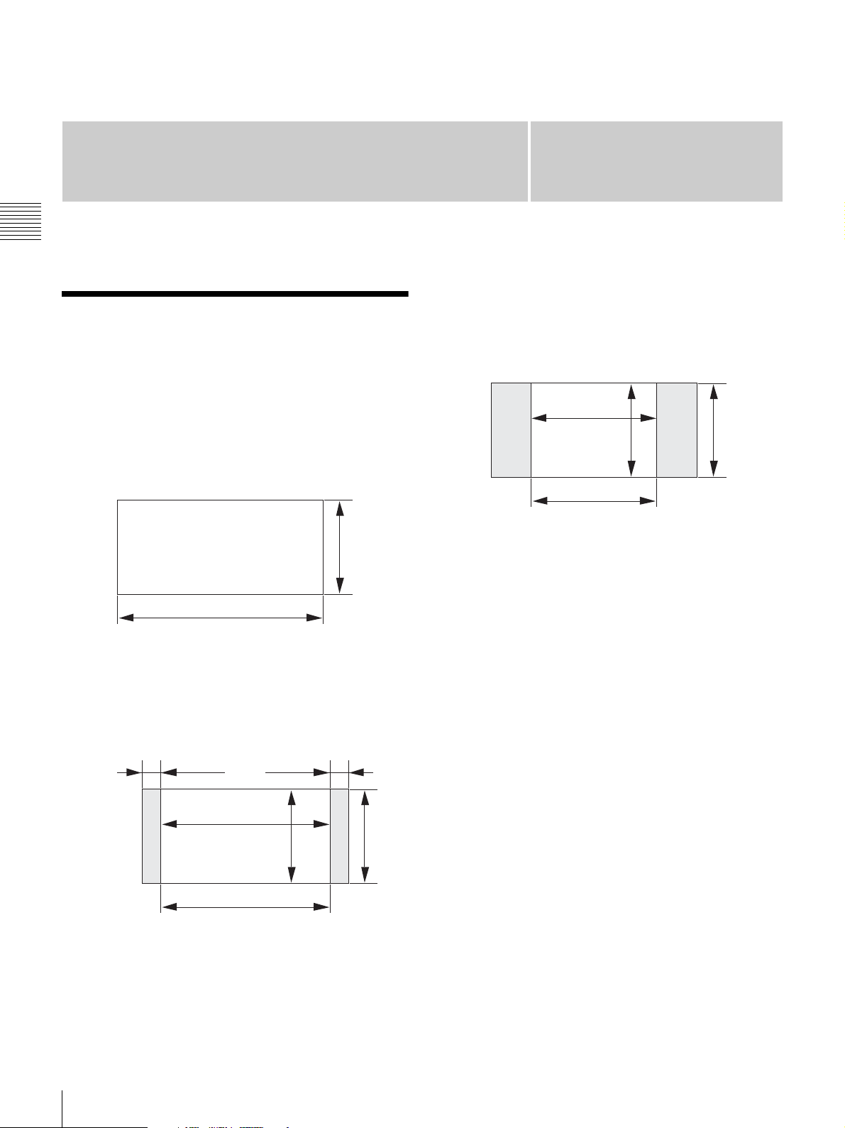
About the Display Mode
The displayed image on the screen varies with the signal
input as illustrated below.
When projecting a 4096-pixel (4K × 2K)
image at the maximum horizontal picture
element
2160 pixel
Chapter
When projecting a 2880-pixel (aspect ratio
4:3) image at the maximum horizontal
picture element
Black bands are displayed on the right and left sides.
4
2880 pixel
2
2160 pixel
3
4096 pixel
When projecting a 3840-pixel (aspect ratio
16:9) image at the maximum horizontal
picture element
Black bands are displayed on the right and left sides.
128 pixel 128 pixel
16
9
3840 pixel
2160 pixel
6
About the Display Mode
Page 7
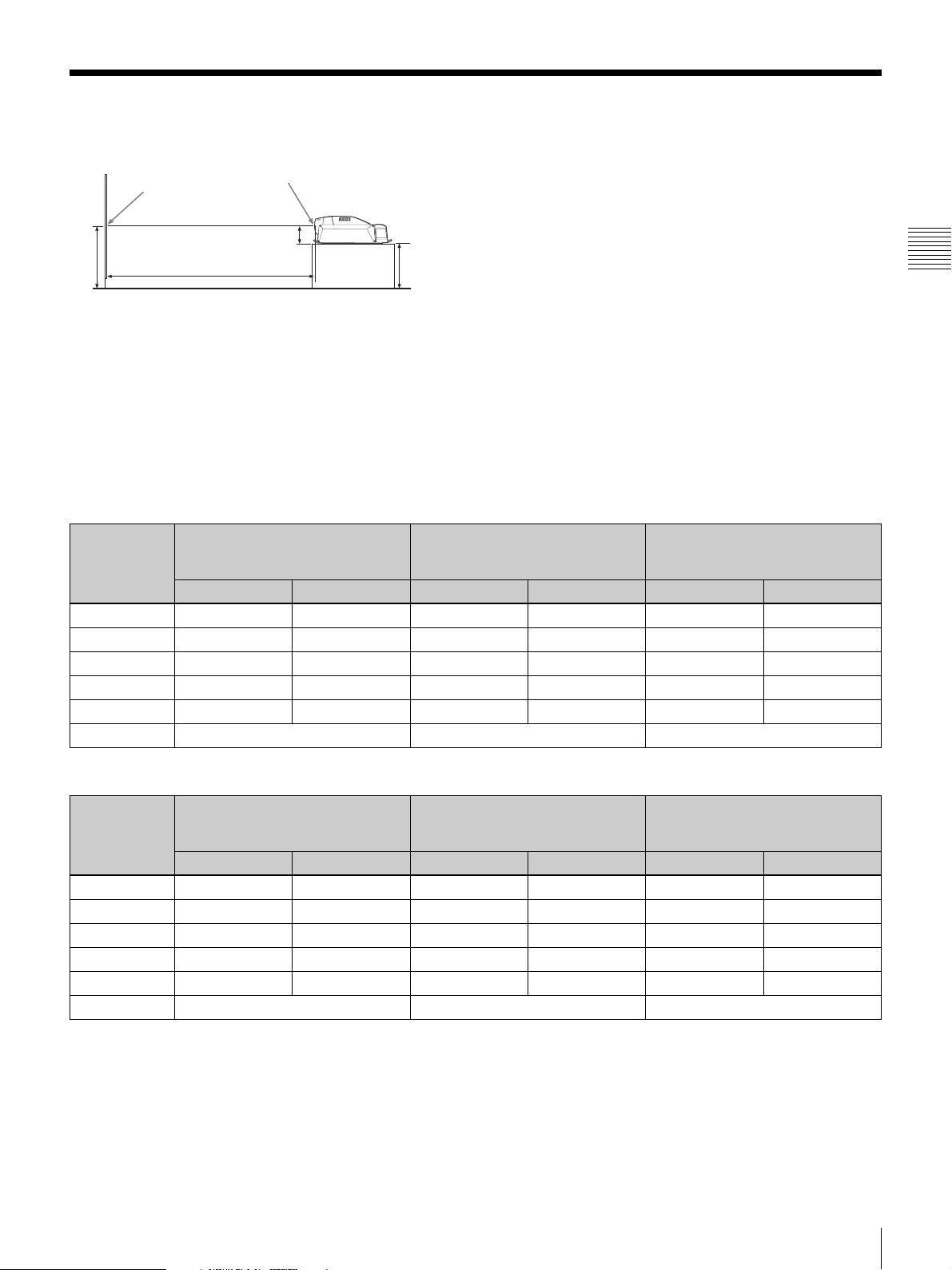
Projection Distance Charts
Screen
Center of screen
Center of lens
A:Distance between the floor and the feet of the projector
A = B – 320 mm (12
5
/8 inches)
B: Distance between the floor and the center of screen
5
L
/8 inches)
A
320 mm (12
B
The alphabetical characters in this section indicate the following measurements:
W: Screen width (unit: mm)
D: Screen diagonal length (unit: inch)
L(min): Minimum distance between the center of lens and screen
L(max): Maximum distance between the center of lens and screen
H: Screen height (different from the aspect ratio of the projected image)
The distance between the lens and the screen varies depending on the attached lens, type of the input signal or size of the
projected image. Choose the most suitable distance (L) depending on the screen size (W or D).
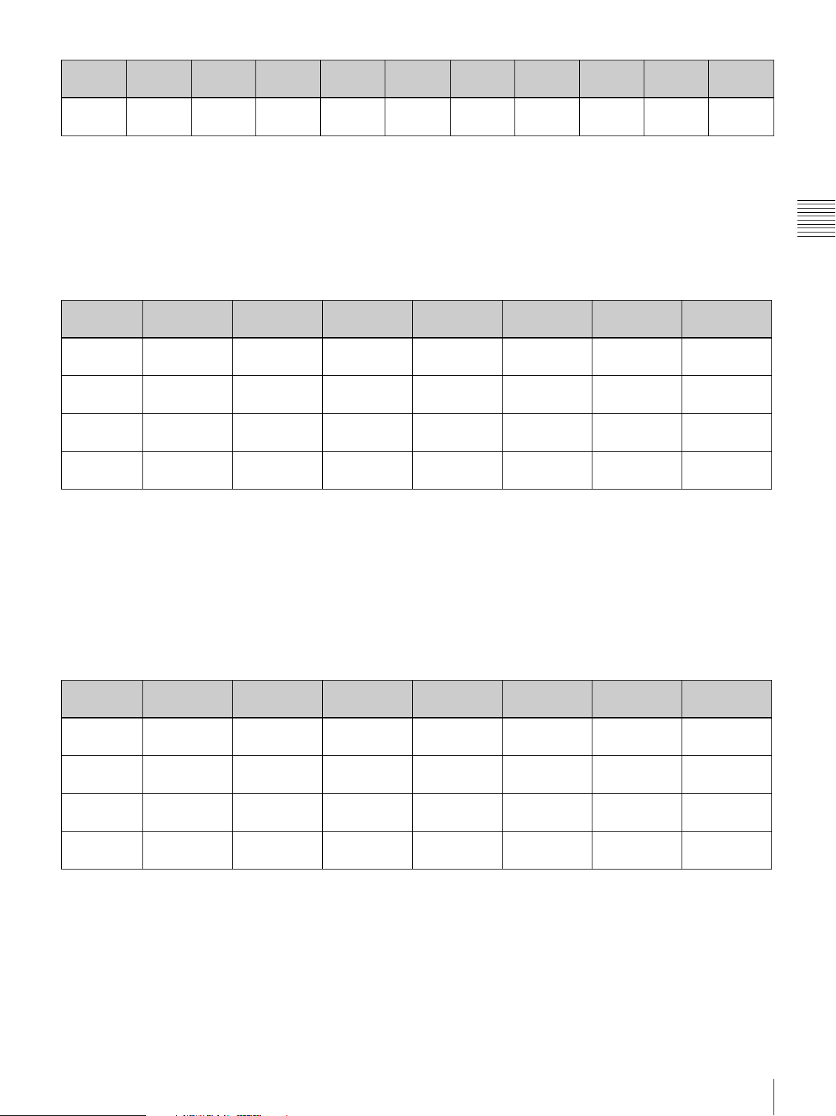
The formula for calculating the projection distance from the screen width (W, unit: mm) is as follows:
Type of lens Projection distance calculation
formula when inputting a 4K × 2K
signal
L(min) L(max) L(min) L(max) L(min) L(max)
LKRL-Z115 1.48 × W 1.81 × W 1.57 × W 1.93 × W 2.11 × W 2.57 × W
LKRL-Z117 1.72 × W 2.39 × W 1.83 × W 2.55 × W 2.45 × W 3.40 × W
LKRL-Z119 1.81 × W 2.94 × W 1.93 × W 3.14 × W 2.57 × W 4.18 × W
LKRL-Z122 2.23 × W 4.03 × W 2.38 × W 4.30 × W 3.17 × W 5.73 × W
LKRL-Z140 3.81 × W 7.12 × W 4.06 × W 7.59 × W 5.42 × W 10.13 × W
LKRL-90 0.9 × W 0.96 × W 1.28 × W
Projection distance calculation
formula when inputting a 16:9
signal
Projection distance calculation
formula when inputting a 4:3
signal
Chapter 2 Installation and Connections
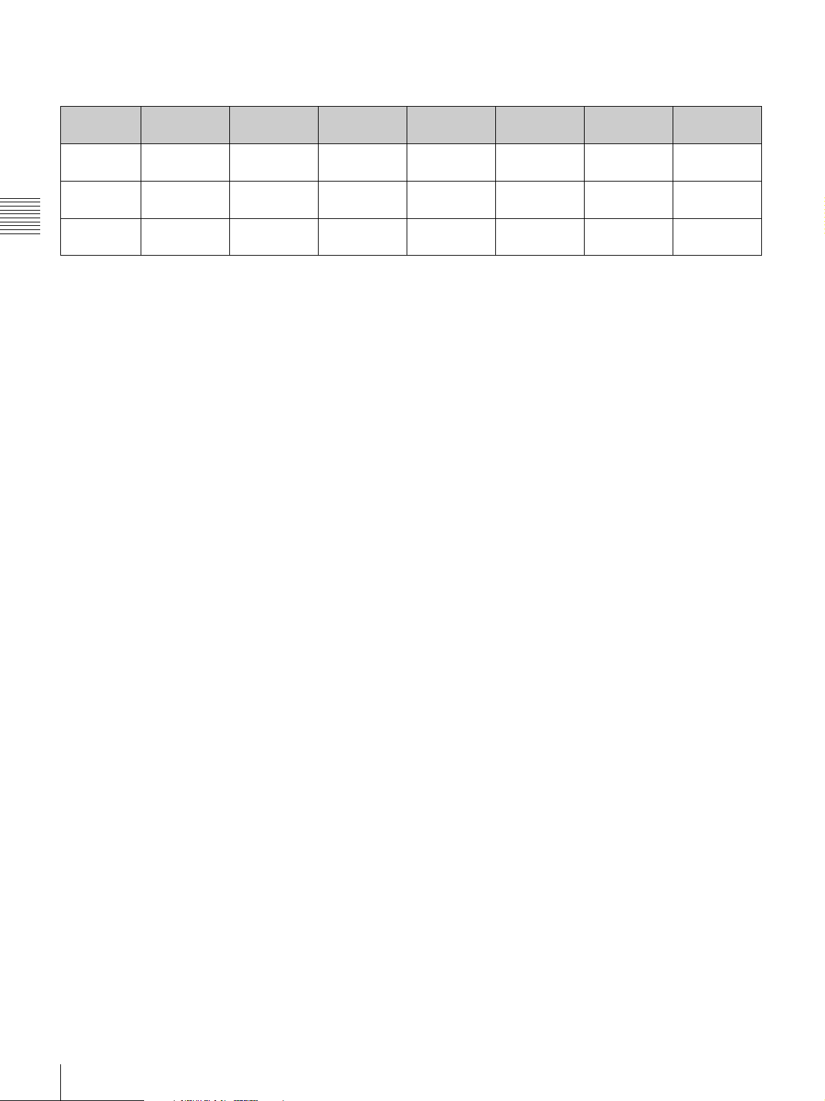
The formula for calculating the projection distance from the screen diagonal length (D, unit: inch) is as follows:
Type of lens Projection distance calculation
formula when inputting a 4K × 2K
signal
L(min) L(max) L(min) L(max) L(min) L(max)
LKRL-Z115 1.31 × D 1.60 × D 1.36 × D 1.67 × D 1.67 × D 2.05 × D
LKRL-Z117 1.55 × D 2.15 × D 1.65 × D 2.30 × D 2.21 × D 3.06 × D
LKRL-Z119 1.63 × D 2.65 × D 1.74 × D 2.83 × D 2.31 × D 3.76 × D
LKRL-Z122 2.01 × D 3.63 × D 2.13 × D 3.86 × D 2.85 × D 5.16 × D
LKRL-Z140 3.43 × D 6.41 × D 3.65 × D 6.83 × D 4.88 × D 9.12 × D
LKRL-90 0.81 × D 0.86 × D 1.15 × D
Projection distance calculation
formula when inputting a 16:9
signal
Projection distance calculation
formula when inputting a 4:3
signal
The projection distance (L) that is decided by the screen width (W) is as shown below.
For the projection distance charts of the optional lenses not mentioned below, refer to the mounting instructions supplied
with each lens.
Projection Distance Charts
7
Page 8
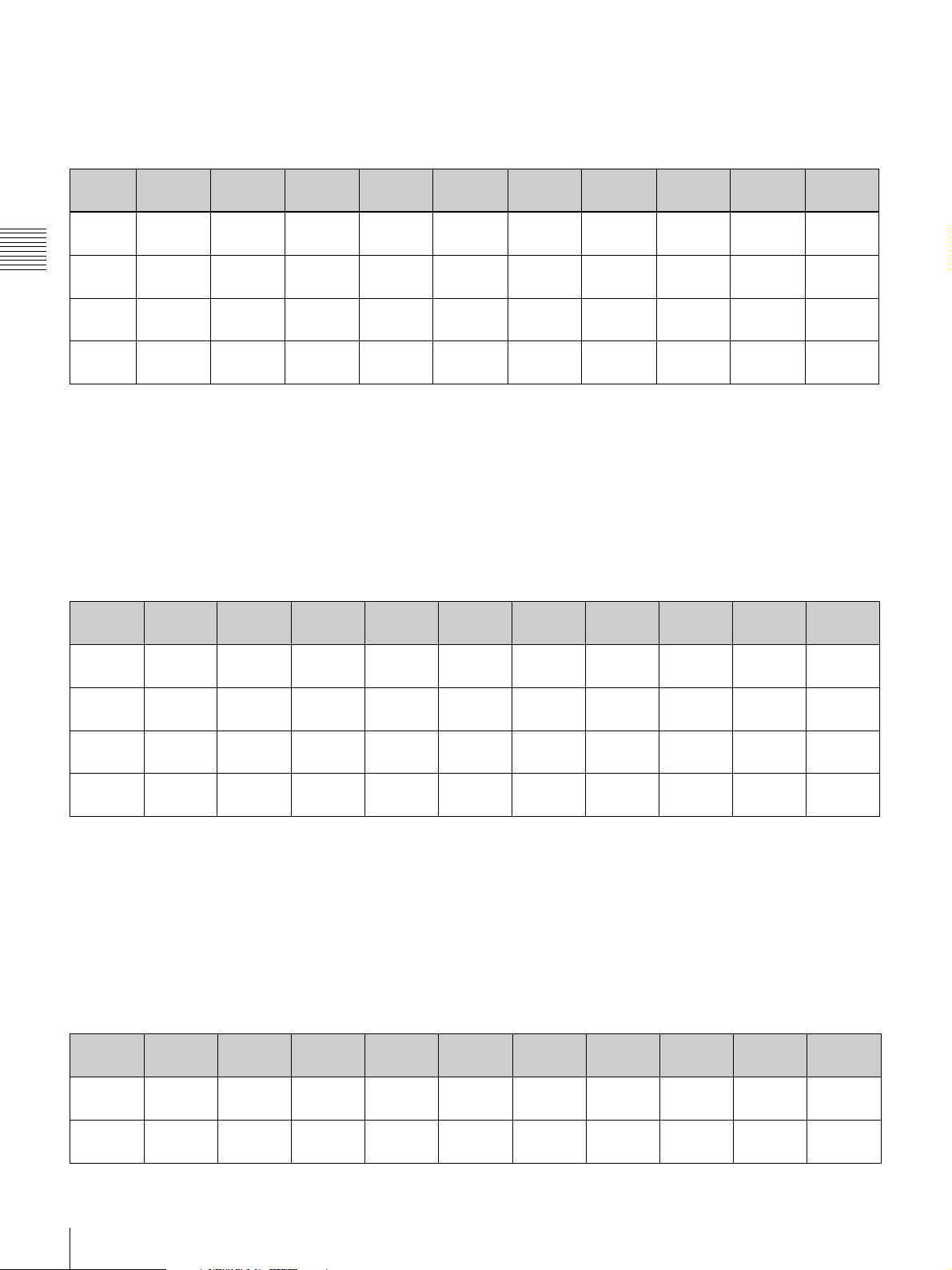
Using the LKRL-Z115 projection lens
When projecting a 4096-pixel (4K × 2K) image at the maximum horizontal picture element
W 4500
1
(177
L(min) 6554
(258)
L(max) 8056
Chapter 2 Installation and Connections
a)
H1
b)
H2
(317
2373
(93
1883
(74
3
1
1
/7)
/8)
mm:
L (min) = (W – 79.675) / 0.67446 L (max) = (W – 63.762) / 0.55067
H1 = W × 0.52730 H2 = W × 0.41840
inch:
L (min) = (W – 3.1368) / 0.67446 L (max) = (W – 2.5103) / 0.55067
H1 = W × 0.52730 H2 = W × 0.41840
a)
Screen height when projecting a 4096 × 2160-pixel (4K single screen) image on the screen.
b)
Screen height when projecting a 4096 × 1714-pixel (aspect ratio 2.39:1) image on the screen.
/5)
/6)
5000
6
/7)
(196
7295
2
/9)
(287
8964
(353)
2637
(103 4/5)
2092
(82 3/8)
6000
2
/9)
(236
8778
(345 3/5)
10780
(424 2/5)
3164
(124 4/7)
2510
(98 5/6)
7000
3
/5)
(275
10261
(404)
12596
(496)
3691
(145 1/3)
2929
(115 1/3)
8000
(315)
11743
(462 1/3)
14412
(567 2/5)
4219
(166)
3347
(131 7/9)
9000
1
/3)
(354
13226
(520 5/7)
16228
(638 8/9)
4746
(186 6/7)
3766
(148 1/4)
10000
5
/7)
(393
14709
(579)
18044
(710 2/5)
5273
(207 5/8)
4184
(164 3/4)
12000
4
(472
17674
(695 5/6)
21676
(853 2/5)
6328
(249 1/7)
5021
(197 2/3)
/9)
14000
1
/6)
(551
20639
(812 4/7)
25308
(996 3/8)
7383
(290 2/3)
5858
(230 5/8)
Unit: mm
(inches)
16000
(630)
23605
(929 1/3)
28940
(1139 3/8)
8438
(332 1/5)
6695
(263 4/7)
When projecting a 3840-pixel (aspect ratio 16:9) image at the maximum horizontal picture element
Unit: mm
(inches)
W 4500
(177
L(min) 7001
(275 5/8)
L(max) 8600
(338
H1
H2
a)
b)
2531
(99
2432
(95
2
3
1
4
/3)
/4)
/6)
/7)
5000
6
(196
/7)
7791
(306 3/4)
9568
(376 5/7)
2813
(110 3/4)
2703
(106 2/5)
6000
2
(236
/9)
9373
(369)
11505
(453)
3375
(132 7/8)
3243
(127 2/3)
7000
3
(275
/5)
10955
(431 2/7)
13442
(529 2/9)
3938
(155)
3784
(149)
8000
(315)
12537
(493 4/7)
15379
(605 1/2)
4500
(177 1/6)
4324
(170 1/4)
9000
1
(354
/3)
14118
(555 5/6)
17316
(681 3/4)
5063
(199 1/3)
4865
(191 1/2)
10000
5
(393
/7)
15700
(618 1/9)
19253
(758)
5625
(221 1/2)
5405
(212 4/5)
12000
4
(472
/9)
18863
(742 2/3)
23127
(910 1/2)
6750
(265 3/4)
6486
(255 3/8)
14000
1
(551
/6)
22027
(867 1/5)
27000
(1063)
7875
(310)
7568
(298)
16000
(630)
25190
(991 3/4)
30874
(1215 1/2)
9000
(354 1/3)
8649
(340 1/2)
mm:
L (min) = (W – 73.944) / 0.63223 L (max) = (W – 59.873) / 0.51629
H1 = W × 0.56250 H2 = W × 0.54050
inch:
L (min) = (W – 2.9112) / 0.63223 L (max) = (W – 2.3572) / 0.51629
H1 = W × 0.56250 H2 = W × 0.54050
a)
Screen height when projecting a 3840 × 2160-pixel (aspect ratio 16:9) image.
b)
Screen height when projecting a 3996 × 2160-pixel (aspect ratio 1.85:1) image.
When projecting a 2880-pixel (aspect ratio 4:3) image at the maximum horizontal picture element
Unit: mm
(inches)
W 3500
(137
L(min) 7271
(286
L(max) 8922
(351 1/4)
4
1
/5)
/4)
4000
1
(157
/2)
8326
(327 4/5)
10213
(402)
4500
1
(177
/6)
9381
(369 1/3)
11504
(453)
5000
6
(196
/7)
10436
(410 8/9)
12795
(503 3/4)
6000
2
(236
/9)
12547
(494)
15377
(605 2/5)
7000
(275
14657
(577)
17959
(707)
3
/5)
8000
(315)
16767
(660 1/8)
20541
(808 5/7)
9000
1
(354
/3)
18878
(743 1/5)
23123
(910 1/3)
10000
5
(393
/7)
20988
(826 2/7)
25705
(1012)
12000
(472
25208
(992 4/9)
30869
(1215 1/3)
4
/9)
8
Projection Distance Charts
Page 9
W 3500
a)
H
(137
2625
(103
4
1
/5)
/3)
4000
1
/2)
(157
3000
(118 1/9)
4500
1
/6)
(177
3375
(132 7/8)
5000
6
/7)
(196
3750
(147 2/3)
6000
2
/9)
(236
4500
(177 1/6)
7000
3
/5)
(275
5250
(206 2/3)
8000
(315)
6000
(236 2/9)
9000
1
/3)
(354
6750
(265 3/4)
10000
(393
7500
(295 2/7)
mm: L (min) = (W – 54.449) / 0.47387 L (max) = (W – 44.662) / 0.38729 H = W × 0.75000
inch: L (min) = (W – 2.1436) / 0.47387 L (max) = (W – 1.7583) / 0.38729 H = W × 0.75000
a)
Screen height when projecting a 2880 × 2160-pixel (aspect ratio 4:3) image.
Using the LKRL-Z140 projection lens
When projecting a 4096-pixel (4K × 2K) image at the maximum horizontal picture element
W 4500
1
(177
/6)
L(min) 16937
4
(666
/5)
L(max) 31943
3
(1257
/5)
H1
H2
a)
b)
2373
(93
1883
(74
3
/7)
1
/8)
mm:
L (min) = (W + 65.304) / 0.26955 L (max) = (W + 33.615) / 0.14193
H1 = W × 0.52730 H2 = W × 0.41840
inch:
L (min) = (W + 2.5710) / 0.26955 L (max) = (W + 1.3234) / 0.14193
H1 = W × 0.52730 H2 = W × 0.41840
a)
Screen height when projecting a 4096 × 2160-pixel (4K single screen) image.
b)
Screen height when projecting a 4096 × 1714-pixel (aspect ratio 2.39:1) image.
5000
6
(196
/7)
18792
(739 5/6)
35466
(1396 2/7)
2637
(103 4/5)
2092
(82 3/8)
6000
2
(236
/9)
22502
(885 8/9)
42512
(1673 2/3)
3164
(124 4/7)
2510
(98 5/6)
7000
3
(275
/5)
26212
(1032)
49558
(1951)
3691
(145 1/3)
2929
(115 1/3)
8000
(315)
29922
(1178)
56604
(2228 1/2)
4219
(166)
3347
(131 7/9)
9000
1
(354
/3)
33632
(1324)
63649
(2505 7/8)
4746
(186 6/7)
3766
(148 1/4)
5
/7)
(393
(1470 1/7)
(2783 2/7)
(207 5/8)
(164 3/4)
12000
(472
9000
(354 1/3)
Unit: mm
(inches)
10000
5
/7)
37342
70695
5273
4184
4
/9)
Chapter 2 Installation and Connections
When projecting a 3840-pixel (aspect ratio 16:9) image at the maximum horizontal picture element
Unit: mm
(inches)
W 4500
1
(177
/6)
L(min) 18062
(711)
L(max) 34047
(1340 3/7)
H1
H2
a)
b)
2531
(99
2432
(95
2
/3)
3
/4)
mm:
L (min) = (W + 61.345) / 0.25254 L (max) = (W + 31.485) / 0.13310
H1 = W × 0.56250 H2 = W × 0.54050
inch:
L (min) = (W + 2.4152) / 0.25254 L (max) = (W + 1.2396) / 0.13310
H1 = W × 0.56250 H2 = W × 0.54050
a)
Screen height when projecting a 3840 × 2160-pixel (aspect ratio 16:9) image.
b)
Screen height when projecting a 3996 × 2160-pixel (aspect ratio 1.85:1) image.
5000
6
(196
/7)
20042
(789)
37803
(1488 1/3)
2813
(110 3/4)
2703
(106 2/5)
6000
2
(236
/9)
24002
(945)
45317
(1784 1/8)
3375
(132 7/8)
3243
(127 2/3)
7000
(275
27961
(1100
52830
(2080)
3938
(155)
3784
(149)
3
/5)
5
/6)
8000
(315)
31921
(1256 3/4)
60343
(2375 3/4)
4500
(177 1/6)
4324
(170 1/4)
9000
1
(354
/3)
35881
(1412 5/8)
67857
(2671 1/2)
5063
(199 1/3)
4865
(191 1/2)
10000
5
(393
39841
(1568 1/2)
75370
(2967 1/3)
5625
(221 1/2)
5405
(212 4/5)
/7)
Projection Distance Charts
9
Page 10
When projecting a 2880-pixel (aspect ratio 4:3) image at the maximum horizontal picture element
W 3500
4
(137
/5)
L(min) 18759
(738 1/2)
L(max) 35266
2
/5)
(1388
a)
H
Chapter 2 Installation and Connections
2625
(103
1
/3)
mm: L (min) = (W + 45.494) / 0.18900 L (max) = (W + 23.598) / 0.09992 H = W × 0.75000
inch: L (min) = (W + 1.7911) / 0.18900 L (max) = (W + 0.92905) / 0.09992 H = W × 0.75000
a)
Screen height when projecting a 2880 × 2160-pixel (aspect ratio 4:3) image.
4000
1
(157
/2)
21404
(842 2/3)
40270
(1585 3/7)
3000
(118 1/9)
4500
1
(177
/6)
24050
(946 5/6)
45274
(1782 4/9)
3375
(132 7/8)
5000
6
(196
/7)
26695
(1051)
50278
(1979 1/2)
3750
(147 2/3)
6000
2
(236
/9)
31986
(1259 1/3)
60287
(2373 1/2)
4500
(177 1/6)
7000
3
(275
/5)
37277
(1467 3/5)
70295
(2767 1/2)
5250
(206 2/3)
Unit: mm
(inches)
8000
(315)
42568
(1676)
80303
(3161 5/9)
6000
(236 2/9)
10
Projection Distance Charts
Page 11
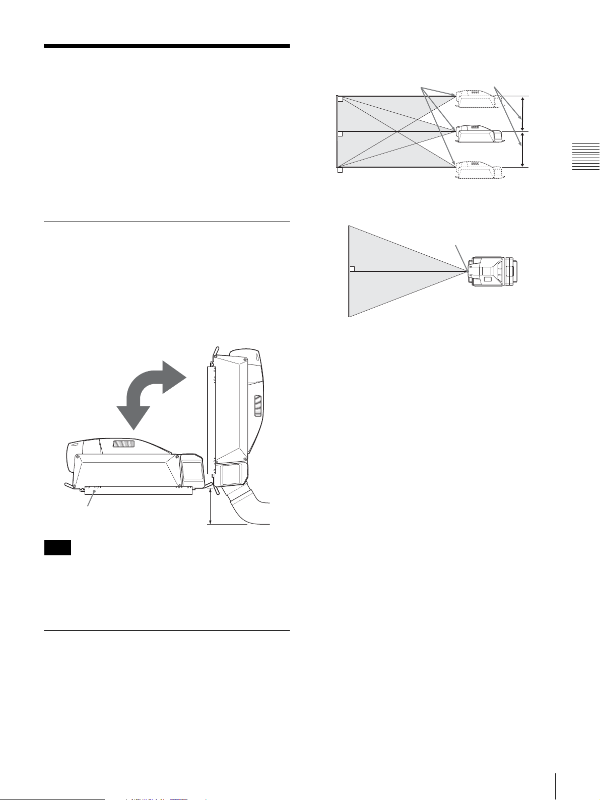
Vertical positioning (side view)
Before Installation
Necessary clearance for installation and
maintenance
For maintenance service and to prevent internal heat buildup, be sure to provide enough room around the projector
when it is installed.
For details, see “Necessary Clearance for Installation and
Maintenance” (page 41)
About the Mounting Platform
This projector can be installed at an angle of ± 90 degrees.
To install at ± 90 degrees angle, attach a mounting
platform that can return to the normal angle as shown in
the figure below to this projector.
The mounting platform is not available as an optional
accessory. Prepare the mounting platform shown in
“Mounting Platform Dimensions” (page 39).
Adjustable range with lens
Screen
Center of lens
shift feature
Horizontal positioning (top view)
Screen
Center of lens
Chapter 2 Installation and Connections
Mounting platform
Note
Leave some
space
Attach the optional LKRA-001 exhaust duct adaptor when
installing at ± 90 degrees angle. When attaching the
adaptor, be sure to provide enough room for smooth
exhaust flow and take care not to bend the duct.
Positioning the Projector towards the Screen
Install the projector so that the center of the lens is between
the bottom edge and the top edge of the screen. You can
move the picture position vertically by half of the screen
vertical size using the lens shift adjustment.
Before Installation
11
Page 12
Installing Lamp Houses
Attaching the Lens
The lamps for the light source of the projector are not
installed in the factory.
Depending on the model, install the optional lamp houses
into the projector.
• LKRX-B110 projection lamp house for SRX-T110
• LKRX-B105 projection lamp house for SRX-T105
Chapter 2 Installation and Connections
For the lamp house installation method, refer to the
operating instructions supplied with each lamp house.
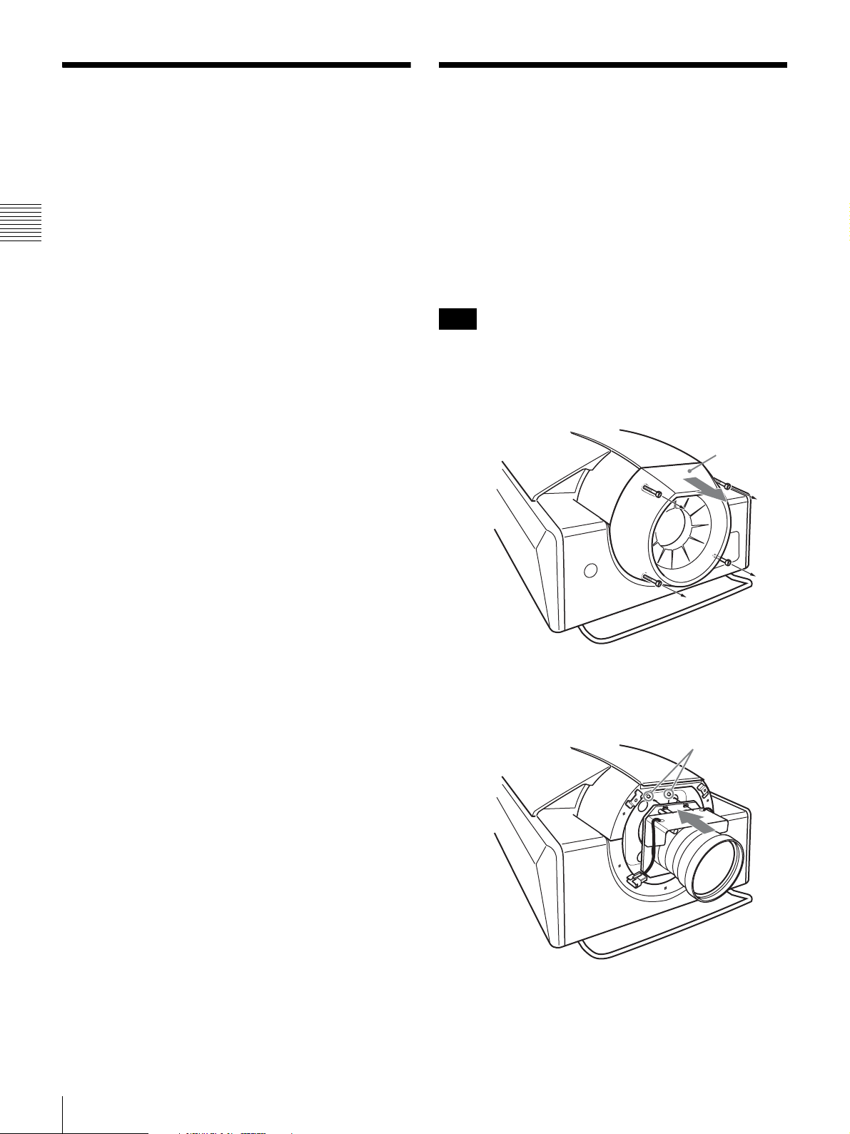
Attach one of the optional lenses to the projector according
to your purpose.
The procedure below describes how to attach the following
lenses to the projector.
• LKRL-Z115 1.48- to 1.81-times zoom lens
• LKRL-Z140 3.81- to 7.12-times zoom lens
For attachment of the optional lenses not mentioned above,
refer to the mounting instructions supplied with each lens.
Note
Handle the lens carefully as it is very heavy.
1
Loosen the four screws on the lens cover with a
hexagonal wrench, then remove the lens cover.
Lens cover
2
Holding the lens with both hands, align the holes on
the lens with the positioning pins on the projector, then
insert the lens straight into the lens attachment part.
Positioning pins
3
Tighten the supplied four screws (M8) with a
screwdriver to secure the lens.
12
Installing Lamp Houses / Attaching the Lens
Page 13
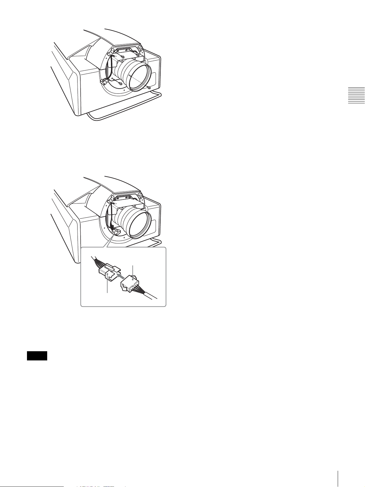
4
Connect the connectors for power focus and zoom on
the lens to those on the projector.
The “FOCUS” and “ZOOM” indications will be found
on the connectors of the lens and the projector. Be sure
to connect each of them correctly.
• The lens scratches easily, so when handling it, always
place it gently on a stable and level surface in a
horizontal position.
• Avoid touching the lens surface.
Chapter 2 Installation and Connections
Connector on the
projector
Connector on the lens
5
Replace the lens cover and tighten it with the four
screws. Be sure to put the connectors and their wires
completely into the projector cabinet before replacing
the lens cover.
Notes
• After replacing the lens with a new one, be sure to
readjust the zoom and focus settings stored in each
FUNCTION button. Otherwise, error message “DATA
LOAD FAILURE LENS POSITION SENSOR” may
appear.
• When removing the screws from the lens to remove the
lens from the projector, be sure to hold the lens with your
hands so that the lens does not drop.
• When attaching the lens, be careful not to tighten the lens
too firmly.
Attaching the Lens
13
Page 14
Using the Optional Input
1
2
2
Board
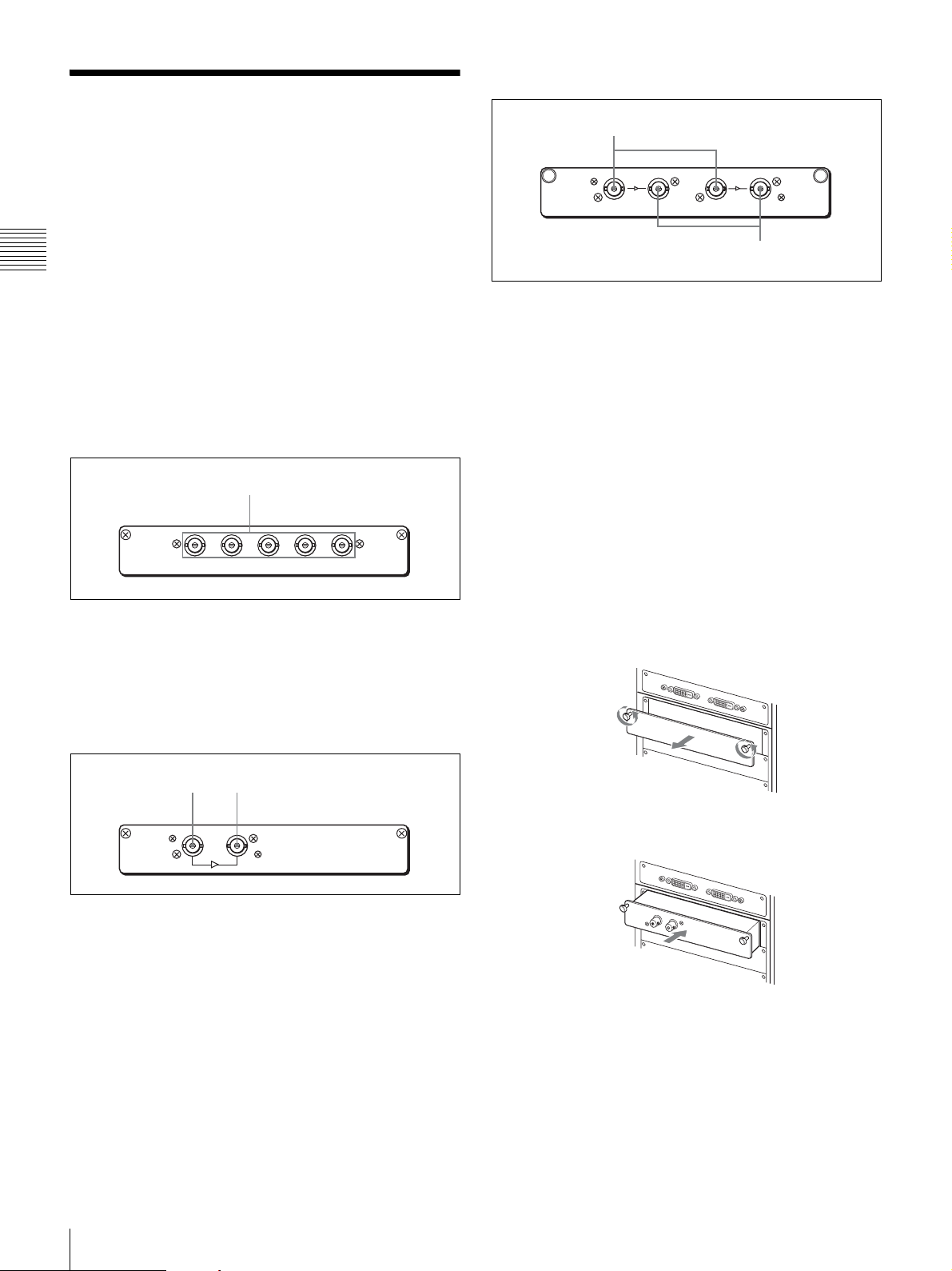
Connectors on the LKRI-003
1
Prepare the optional input boards mentioned below
depending on your system requirements, and attach them
to the input board attachment part on the left side of the
projector.
Chapter 2 Installation and Connections
• LKRI-001 analog input board
• LKRI-002 HD-SDI (4:2:2) input board
• LKRI-003 HD-SDI/DC-SDI (4:4:4) input board
For information on the input boards not mentioned above,
refer to the operating instructions supplied with each input
board.
Connectors on the LKRI-001
H
R(Pr/Cr) G(Y/Y) B(Pb/Cb)
a R (Pr/Cr)/G (Y/Y)/B (Pb/Cb)/HD/VD input
connectors (BNC type)
Inputs the RGB, component or high definition signal from
a computer or component equipment.
D
VD
OUTIN
LINK A LINK B
OUTIN
a LINK A/LINK B IN (HD-SDI input) connectors
(BNC-type)
Connect to the output connectors of an HDCAM-SR video
recorder/player to input an HD-SDI or DC-SDI signal.
Connection of both LINK A and LINK B IN connectors
allows Dual-link HD-SDI or Dual-link DC-SDI signal
input.
b LINK A/LINK B OUT (HD-SDI output)
connectors (BNC-type)
Output the input signals supplied from the LINK A/LINK
B IN connectors by loop-through when the projector is
turned on.
Attaching the input board
1
Loosen the two screws fully and remove the panel.
Connectors on the LKRI-002
1
OUTIN
a IN (HD-SDI input) connector (BNC type)
Connect to the output connector of an HDCAM video
recorder/player to input an HDTV serial digital signal.
b OUT (HD-SDI output) connector (BNC type)
Outputs a digital signal input through the IN connector
when the projector is turned on.
2
Push in the input board along the rails.
I
N
O
U
T
14
Using the Optional Input Board
Page 15

3
Tighten the two screws firmly with a torque of 0.8±0.1
N
·m.
IN
O
U
T
Attaching the Exhaust Duct Adaptor
Attach the optional exhaust duct adaptor according to the
installation situation.
• LKRA-001 8-inch exhaust duct adaptor
To remove the input board, loosen the screws fully and
pull it out.
For details on attaching the exhaust duct adaptor, refer to
the Installation Instructions supplied with LKRA-001.
Chapter 2 Installation and Connections
Attaching the Exhaust Duct Adaptor
15
Page 16

Connecting the Projector
When you connect the projector, make sure to:
• Turn off all equipment before making any connections.
• Use the proper cables for each connection.
• Insert the cable plugs firmly; loose connections may
increase noise and reduce performance of picture
signals. When pulling out a cable, be sure to pull it out
Chapter 2 Installation and Connections
from the plug, not the cable itself.
• When installing the optional input board, consult your
Sony dealer.
Refer also to the instruction manuals of the equipment to
be connected.
Left side
AUXDVI-D
INTER LOCK
ETHERNET RS232C
DVI-D connector AUX connector
Connecting a Computer Equipped with a DVI-D Connector
Connect a computer to the DVI-D connector on the
optional LKRI-004 DVI interface board or LKRI-005
HDCP DVI board attached to the input board attachment
part. A progressive DVI signal can be input.
Setting the DIP switch
Set the following DIP switch(es) at the bottom of LKRI004 and LKRI-005 boards depending on the input signal
type of the connected computer.
• S101 on LKRI-004 board
• S101 and S102 on LKRI-005 board
For details on setting the DIP switches, refer to the
Operating Instructions of LKRI-004 (supplied with LKRI-
004) or the Operating Instructions of LKRI-005 (supplied
with this projector).
Connecting with a computer
The illustration below shows an example of connection
with INPUT A of the projector.
DVI cable
(not supplied)
to DVI output
Computer
HDCP (High-bandwidth Digital Content Protection) DVID signal can also be input when the input signal with
specified resolution is input from LKRI-005.
For details, refer to the Operating Instructions of LKRI-
005.
Notes
• According to the input signal type, set “Signal Mode” on
“Input Source” in the PICTURE CONTROL window of
the SRX Controller. (page 25)
• When an extension cable is used, the signal may not be
input correctly due to signal reduction.
• If you input 10-bit signals from a DVI-D connector only
(10-bit single mode), a DVI cable compatible with the
Dual-link is required.
16
Connecting the Projector
Page 17

Connecting with a Computer
Connecting with HD-SDI Equipment
Equipped with an Analog RGB
Connector
Attach the optional LKRI-001 analog input board to the
input board attachment part on the projector, and connect
with a computer.
Left side
AUXDVI-D
R(Pr/Cr)B(Pb/Cb)HD VDG(Y/Y)
OUT
IN
INTER LOCK
ETHERNET RS232C
R/G/B/HD/VD
connectors
IN OUT
Monitor cable (not supplied)
Attach the optional LKRI-002 HD-SDI (4:2:2) or LKRI-
003 HD-SDI (4:4:4) input board to the input board
attachment part, and connect the HDCAM recorder/player.
The illustration below shows an example with the LKRI-
002 attached on INPUT B.
Left side
AUXDVI-D
IN OUT
INTER LOCK
ETHERNET RS232C
IN connector
IN connector
HD-SDI connecting
cable (not supplied)
Chapter 2 Installation and Connections
to monitor output
Computer
Note
Select “RGB” in “Signal Mode” of “Input Source” in the
PICTURE CONTROL window.
For details, see page 25.
to HD-SDI output
SRW-5000
HD DIGITAL VIDEO CASSETTE RECORDER
HDCAM recorder/player, etc.
Note
When the LKRI-003 is attached to the projector, select the
type of signal with “Signal Mode” of “Input Source” in the
PICTURE CONTROL window. For Single-link input,
select “YPbPr” or “YPbPr FULL”. For Dual-link input,
select “RGB” or “RGB FULL”.
For details, see page 25.
Connecting the Projector
17
Page 18

Connecting with Component/Video GBR Equipment
Attach the optional LKRI-001 analog input board to the
input board attachment part on the projector, and connect
with a DVD recorder/player or analog video equipment
equipped with the component output, or an high-definition
equipment equipped with a video GBR connector.
Chapter 2 Installation and Connections
Left side
AUXDVI-D
R(Pr/Cr)B(Pb/Cb)HD VDG(Y/Y)
IN
OUT
INTER LOCK
ETHERNET RS232C
IN OUT
R/Pr / G/Y / B/Pb
connectors
Connecting the AC Power
Cord
Use an AC power cord that supports 8AWG, 250 V, 40 A
or higher.
Follow the steps below to connect the three-wire power
cord to the AC IN terminal on the left side of the projector.
WARNING
• Connection of the main power and the electric wiring
work should be done by qualified electricians only.
• Do not plug the power cord into the power supply before
completing the following operations.
1
Remove the two screws on the terminal cover and
remove it.
Component cable, etc
(not supplied)
to component output/
video GBR
Betacam, DVD recorder/player, etc.
Note
When connecting to the output of HD component
equipment, set “Signal Mode” of “Input Source” in the
PICTURE CONTROL window to “YPbPr”, and when
connecting to the output of HD video GBR equipment, set
to “RGB”.
For details, see page 25.
2
Remove the two screws on the cable clamp and
remove it.
L
N
Cable clamp
3
Pass the AC power cord through the hole beneath the
terminal, and tighten the screw for each wire as
illustrated.
L
N
L
N
18
Connecting the AC Power Cord
Page 19

4
Fix the AC power cord securely with the cable clamp
and the two screws removed in step 2.
5
Replace the terminal cover using the two screws
removed in step 1.
Installing the SRX Controller
Install the supplied SRX Controller on the computer used
for controlling.
For the SRX Controller installation method, refer to the
Operating Instructions of this projector.
Chapter 2 Installation and Connections
Installing the SRX Controller
19
Page 20

Setting the Projector
Start the SRX Controller. Display the Control Function
Menu window, open the SETTING window, and set the
functions of the projector.
For details on the Control Function Menu window, see
page 24.
Chapter 2 Installation and Connections
Displaying the SETTING Window
1
Click the “SETTING” button on the Control Function
Menu window.
The authentication dialog appears.
2
Enter the password in the “Password” text box, and
click the “OK” button.
The default setting of the password is “setting”.
The SETTING window opens.
Owner Information
The Owner Information window is used to set information
on this projector.
Owner
Name: Enter the name of an owner of the projector.
Organization: Enter the name of an organization.
Projector
Region: Enter the region where the projector is used.
Location: Enter the location where the projector is
installed.
Name: Enter the desired name.
Memo: Use to enter notes.
Setting items
3
Click the desired setting item on the left of the
window.
The selected setting window opens.
When you have completed the settings in
each window
Click the “APPLY” button at the lower part of each
window. The settings are registered.
Date & Time
The Date & Time window is used to set the current date
and time.
Time Zone
Sets the time difference in the area where the projector is
installed. Select the time zone from the drop-down list
displayed by clicking .
Adjust clock for daylight saving changes: When you
click the check box, the clock is automatically
adjusted according to the daylight saving time of the
selected time zone.
20
Setting the Projector
Page 21

Date & Time
Clicking on the date text box displays a calendar. Set
the current date using the calendar.
To set the current time, click the hour or minute in the time
text box and set it by clicking .
Time Server(NTP Server)
Enter the IP address of the NTP server.
Network
The Network window is used to configure the network
setting for the projector.
Mail Report
The Mail Report window is used to set sending e-mail to
report the used time of the projection lamps or the
operating hours of the projector for maintenance to the
preset addresses.
Chapter 2 Installation and Connections
Report Timing
Lamp Timer Reminder: Presets the timing when e-mail
is sent for reporting the used time of the lamps.
Maintenance Reminder: Presets the timing when e-mail
is sent for reporting the elapsed operating time of the
projector for maintenance.
Re-count: Resets the elapsed operating time when you
check the check box.
Internet Protocol (TCP/IP)
Sets the IP address of the projector.
Click either radio button.
Obtain an IP address automatically (DHCP): Click
when you obtain an IP address automatically from a
DHCP server.
Specify an IP address: Click when you specify a fixed IP
address. Sets the following items.
IP Address: Enter the IP address of the projector.
Subnet Mask: Enter the subnet mask.
Default Gateway: Enter the default gateway.
Primary DNS: Enter the IP address of a primary
DNS server.
Secondary DNS: Enter the IP address of a secondary
DNS server.
LAN
MAC address: Displays the MAC address of the
projector.
Speed: Sets the link speed of Ethernet. Select from the
drop-down list displayed by clicking .
Reporting Sources/Destination
FROM: Enter the e-mail address from which e-mails are
sent.
Email Address: Enter the e-mail addresses to which you
send e-mails as TO and CC.
Reporting Contents
Error: Check the addresses to which you want to send e-
mail for reporting errors.
Lamp Timer/Maintenance: Check the addresses to
which you want to send e-mail for reporting “Lamp
Timer” and “Maintenance”.
Mail Server
Outgoing Mail Server (SMTP): Enter the SMTP
(sending mail) server name or the IP address of the
SMTP server.
Requires Authentication: If authentication is required
when you send e-mails, check the check box and
select either way for authentication.
POP before SMTP: Selects when “POP before
SMTP” is necessary when e-mail is sent.
POP3 Server: Enter the POP3 server name or the
IP address of the POP3 server.
Account Name: Enter the user name to log in to
the POP3 server.
Password: Enter the password of the user to log in
to the POP3 server.
Setting the Projector
21
Page 22

SMTP Authentication: Selects when “SMTP
Authentication” is necessary when e-mail is sent.
Account Name: Enter the user name to log in to
the SMTP server.
Password: Enter the password of the user to log in
to the SMTP server.
Send Test Mail: Check the check box if you want to send
a test mail.
Chapter 2 Installation and Connections
PC Communication
The PC Communication window is used to configure for
communication between the projector and the computer
for controlling the projector.
List box
Projector Identifying
Configures the projector.
Port No.: Enter the UDP port number.
Interval: Select the interval at which the IP packets are
sent.
Select from the drop-down list displayed by
clicking .
Broadcast Address: Enter the broadcast address.
: Registers the entered IP address in the list.
: Deletes the IP address from the list.
List box: Displays the registered broadcast addresses.
Controlling PC Destination
Configures the computer for controlling the projector.
Port No.: Enter the TCP port number.
Time-out: Select the time when the communication is to
end.
Select from the drop-down list displayed by
clicking .
Accept connections from these hosts: Enter the IP
address of a host who is allowed to access the
projector.
: Registers the entered IP address in the list.
: Deletes the registered IP address from the list.
List box: Displays the registered IP addresses of the
hosts allowed to access the projector.
Network Block Reboot
Restarts the Network CPU after the PC Communication
settings complete. Click the “REBOOT” button to restart.
SNMP
The window is used to set up SNMP (Simple Network
Management Protocol).
List box
SNMP
sysName: Enter the characters for the standard MIB
sysName.
Contact: Enter the characters for the standard MIB
sysContact.
Location: Enter the characters for the standard MIB
sysDescr.
Send authentication trap: Selects when you permit
sending authentication trap.
Accept SNMP packets from any host: Selects when you
permit access to the projector from any host.
Accept SNMP packets from these hosts: Selects when
access to the projector is allowed for specified hosts
only. Enter the IP address of the host permitted to
access the projector in the text box.
: Register the entered IP address in the list.
: Deletes the registered IP address from the list.
List box: Displays the registered IP addresses of the
hosts allowed to access.
Community: Selects and edit the community name.
“Add” button: Click to add the selected community
name.
“Edit” button: Click to enter edit mode for attributes
of the selected community.
“Remove” button: Click to remove the selected
community.
Community Name: Clicking the “Edit” button displays
the community name whose attributes can be edited,
and the following items are activated:
Rights: Selects the access right.
“Set to List” button: Click to apply the change of
attributes.
22
Setting the Projector
Page 23

“Cancel” button: Click to cancel the change of
attributes.
Trap Destinations: Enter the IP address of a host for trap
destination.
: Register the entered IP address in the list.
: Deletes the registered IP address from the list.
List box: Displays the registered IP addresses of the
hosts for trap destination.
Profile
The Profile window is used to save the projector settings in
the computer for controlling the projector, or to load the
settings saved on the computer for controlling the projector
onto the projector.
Save
Check the menu items (projector settings) which you want
to save to the computer for controlling the projector.
File: Select and edit the filename to be saved. Click to
specify the file to be saved.
“SAVE” button: Click to save the projector settings to the
specified file. Only the values of checked items will
be saved.
Chapter 2 Installation and Connections
Load
Check the menu items (projector settings) which you want
to load to the projector from the computer for controlling
the projector.
The settings for some functions cannot be loaded to the
projector when the computer for controlling the projector
is connected to the projector via network. The menu items
for these functions cannot be checked.
File: Select and edit the filename saved on the computer.
Click to specify the saved file.
“LOAD” button: Click to load the settings saved in the
specified file to the projector. Only the values of
checked items will be loaded.
Setting the Projector
23
Page 24

Adjustments and Settings
Using the SRX Controller
Chapter 3 Adjustments and Settings Using the SRX Controller
Displaying the Control Function Menu Window
When you install the supplied SRX Controller in a
computer, you can operate the picture adjustments, input
signal settings, installation settings, etc. from the
computer.
Some of the picture adjustments are available using the
supplied Remote Commander.
1
Double-click the icon of the SRX Controller in the
desktop window of the computer.
The Program Launcher screen appears.
Chapter
For details on each setting window, see the relevant
window pages.
To clear the Control Function Menu
window
Select “Quit” from the “File” menu on the menu bar, or
click the (close) button.
To reset the settings that have been
adjusted
Clicking the “RESET” button in the PICTURE
CONTROL window resets all the settings of the items for
“Signal Adjust” to their factory preset values. To reset the
settings of the items for “Frame Adjust” in the COLOR/
FRAME window, click the “RESET” button in the
COLOR/FRAME window.
3
2
Select the projector you want to operate by doubleclicking the projector.
The T100 Controller starts and the Control Function
Menu window appears.
3
Click any of the “PICTURE CONTROL”, “COLOR/
FRAME” and “INSTALLATION” buttons to display
the desired control window.
To register the settings that have been
adjusted
You can register the settings that have been adjusted in the
control windows to FUNCTION 1 to 7. As the default
setting, the settings are registered to FUNCTION 1. To
register the settings to FUNCTION 2 to 7, click one of the
FUNCTION 2 to 7 radio buttons, then adjust the items in
each window.
You can recall it later to project the picture with the desired
setting by clicking one of the FUNCTION radio buttons.
You can also recall the settings registered to the
FUNCTION 1, 2 or 3 button with the FUNCTION 1, 2 or
3 button on the Remote Commander.
Note
When you click the FUNCTION button to switch to
another FUNCTION setting, the picture will be cut off for
up to about 10 seconds. The picture with the selected
FUNCTION setting will then appear on the screen.
For details on the items that can be registered, refer to the
Operating Instructions of this projector.
24
Displaying the Control Function Menu Window
Page 25

About the items that cannot be adjusted
Items that cannot be adjusted depending on the input signal
are not displayed in the window.
For details, see “Input Signals And Adjustable/Setting
Items” on page 34.
Log function
Clicking the “Save Log” in the “File” menu on the menu
bar in the Control Function Menu window saves the
communication log between the T100 Controller and this
projector up to the moment “Save Log” is clicked. Up to 5
MB can be saved.
PICTURE CONTROL Window
The PICTURE CONTROL window is used to select the
input source or to adjust the picture quality.
When the screen mode is set to dual-screen mode or quadscreen mode, the items can be independently adjusted for
each input channel displayed on the screen.
Chapter 3 Adjustments and Settings Using the SRX Controller
Board
Shows the input board installed in the relative input board
slot of the projector.
Input Source
Signal Mode: Click to open the drop-down list to
select the type of signal input from equipment
connected to the optional input board.
When the LKRI-004 or LKRI-005 is installed
Select the input signal type of progressive DVI-D
signals.
When used in normal, select “8bit Single Full”, which
is compatible with DVI1.0 standard and the signal
level is Full Range compliance.
When the DTV signal is input, select “8bit Single
Limited”, which is compatible with DVI1.0 standard
and the signal level is Limited Range compliance.
When the 10-bit signal based on Sony’s unique
specification is input, select “10bit Twin Full” or
“10bit Single Full” for a signal of Full Range
PICTURE CONTROL Window
25
Page 26

compliance, or “10bit Twin Limited” or “10bit Single
Limited” for a signal of Limited Range compliance.
When the LKRI-001 is installed
Select “YPbPr” to input a high-definition signal from
component equipment, and “RGB” to input a highdefinition signal from video GBR equipment.
When the LKRI-003 is installed
For Single-link input, select “YPbPr” or “YPbPr
FULL”.
For Dual-link input, select “RGB” or “RGB FULL”.
When “RGB” or “YPbPr” is selected, in the case that
a 10-bit HD-SDI signal is input and “Contrast” is set
to 90 in “Signal Adjust” of the PICTURE CONTROL
Chapter 3 Adjustments and Settings Using the SRX Controller
window, mapping is done so that HD-SDI signal data
values
1)
of 64 to 960 are converted to the video levels
of 0 to 100% to display an image on the projector.
When “RGB FULL” or “YPbPr FULL” is selected, in
the case that a 10-bit HD-SDI signal is input and
“Contrast” is set to 90 in “Signal Adjust” of the
PICTURE CONTROL window, mapping is done so
that HD-SDI signal data values of 0 to 1023 are
converted to the video levels of 0 to 100% to display
an image on the projector. In this case, inhibition
codes included in a 10-bit HD-SDI signal (data area 0
to 3, and 1020 to 1023) are blocked out.
1)
Data value 64 of a 10-bit HD-SDI signal input is
equivalent to the video level of 0% (black), and data value
960 equivalent to 100% (white).
I/P Mode: Selects the I/P conversion mode. Depending on
the input signal source, set the mode to “Interlace” or
“PsF”.
Clicking the “RESET” button resets the following four
settings to the factory preset values.
Contrast: Adjusts the picture contrast. The higher the
setting, the greater the contrast.
Brightness: Adjusts the picture brightness. The higher the
setting, the brighter the picture.
Color: Adjusts the color intensity. The higher the setting,
the greater the intensity.
Sharpness: Adjusts the picture sharpness. The higher the
setting, the sharper the picture. The lower the setting,
the softer the picture.
Notes
• This item is available with the interlace or PsF
signal input.
• When the LKRI-004 or LKRI-005 is installed, this
item is not available.
Signal Info (Information)
Shows the horizontal and vertical frequencies of the input
signal automatically. The values are approximate.
The type of the input signal is also displayed.
fH: Displays the horizontal frequency.
fV: Displays the vertical frequency.
Signal Adjust
Adjusts the picture quality of the input signal.
Clicking increases the setting value, and
decreases it.
26
PICTURE CONTROL Window
Page 27

COLOR/FRAME Window
The COLOR/FRAME window is used to adjust the input
signal.
When the screen mode is set to dual-screen mode or quadscreen mode, the items can be independently adjusted for
each input channel displayed on the screen.
Board
Shows the input board installed in the relative input board
slot of the projector.
Adobe RGB: Select when projecting Adobe RGB
compatible computer signals.
CUSTOM: Select when projecting a signal using the
color gamut defined by the user. The default value is
the same as DCDM.
Color Temp (temperature): Selects the color
temperature from among “DCI W/P”, “6500K”,
“9300K”, “CUSTOM1”, “CUSTOM2” and
“CUSTOM3”. 6500K is preset in CUSTOM1 to 3
settings in the factory.
“6500K” is recommended for a normal highdefinition signal or RGB signal. Set this item to “DCI
W/P” to project a movie source.
Gamma: Selects a gamma correction curve. The smaller
the value, the brighter the image. Select the setting
depending on the signal source. “2.2” is
recommended to project a normal high-definition
signal or RGB signal.
The gamma value that can be selected will differ
according to the optional input board.
When the LKRI-001 or LKRI-002 is installed
Select from “2.6”, “2.2” or “1.8”.
When the LKRI-003, LKRI-004 or LKRI-005 is
installed
Select “2.6” or “2.2”, or set a value from 1.80 to 2.59
(except 2.20) in 0.01 steps according to the signal
input. This allows projection of an image with
optimum brightness.
To set the gamma value in 0.01 steps, set “Gamma” to
“1.8”, and click the “CUSTOMIZE” button. Input the
values in the Input Gamma Data screen and press the
“OK” button.
Chapter 3 Adjustments and Settings Using the SRX Controller
Color
Adjusts the items so that you can obtain precise color
reproduction.
If the color of an image is not correct, check the setting of
“Color Space” first.
Select the setting from the drop-down list displayed by
clicking .
Color Space: Selects the color gamut.
sRGB(709): Select when projecting a normal high-
definition signal or RGB signal.
DCDM: Select when projecting a signal source using
the Minimum D-Cinema Color Gamut defined by the
DCI Specifications Book/Version 1.0.
CIE XYZ: Select when projecting an XYZ signal
from LKRI-003.
Note
Set “Signal Mode” of “Input Source” in the PICTURE
CONTROL window to “RGB FULL”.
When a signal is input from the connector
on the LKRI-004 or LKRI-005
When you set each item in “Color”, the setting will be
written to the color space description area of the EDID
ROM.
The values to be written to the EDID ROM are shown
below.
Color Space settings
sRGB(709): Red (0.6400, 0.3300), Green (0.3000,
0.6000), Blue (0.1500, 0.0600)
Adobe RGB: Red (0.6400, 0.3300), Green (0.2100,
0.7100), Blue (0.1500, 0.0600)
DCDM, CIE XYZ, CUSTOM: Red (0.6800,
0.3200), Green (0.2650, 0.6900), Blue (0.1500,
0.0600)
Color Temp settings
COLOR/FRAME Window
27
Page 28

6500K: White (0.3127, 0.3290)
9300K: White (0.2840, 0.2970)
DCI W/P: White (0.3140, 0.3510)
CUSTOM1 to CUSTOM3: White (0.3127, 0.3290)
(default values)
Gamma settings
2.6: 2.6
2.2: 2.2
CUSTOM: Value set using CUSTOM
Frame Adjust
Adjusts the horizontal size and the position of the picture.
Clicking increases the setting value, and
Chapter 3 Adjustments and Settings Using the SRX Controller
decreases it.
Clicking the “RESET” button resets all the settings of
“Frame Adjust” to the factory-preset values.
INSTALLATION Window
The INSTALLATION window is used to adjust the
projected picture and to change the lamp output, etc.
Dot Phase: Adjusts the phase of the SXRD panels and the
input signal. Adjust the value to obtain the clearest
picture.
H Size: Adjusts the horizontal size of the picture according
to the input signal. As the setting value increases, the
horizontal size of the picture becomes larger.
H Shift: Adjusts the horizontal position of the picture. As
the setting value increases, the picture moves to the
right. As the value decreases, the picture moves to the
left.
V Shift: Adjusts the vertical position of the picture. As the
setting value increases, the picture moves up. As the
value decreases, the picture moves down.
Notes
• Adjustment of “Dot Phase” and “H Size” is available
only for analog RGB signals input from a computer.
• If the position of the picture is not adjusted correctly,
noise may appear in the blank portion of the screen. This
is not a malfunction of the projector. Adjust the picture
position correctly with “Frame Adjust”.
LENS CONTROL
Adjusts the projected picture on the screen.
Zoom +/–: Adjusts the size of the picture. Clicking
enlarges the picture size, and reduces the picture
size.
Focus +/–: Adjusts the picture focus. Clicking focuses
on a picture further back. Clicking focuses on a
forward picture.
Shift +/–: Adjusts the vertical position of the picture.
Clicking moves the picture upward. Clicking
moves it downward.
ELECTRIC V SHIFT FUNCTION
Adjusts the vertical position of the projected pictures
electrically. As the setting value increases, the picture
moves upward. As the setting value decreases, the picture
moves downward.
Clicking the “RESET” button resets the setting to the
factory-preset values.
28
INSTALLATION Window
Notes
• This function is effective in the following cases:
- When single-screen mode is selected
- When quad-screen mode is selected and
“PROGRESSIVE DISPLAY MODE” is set to “On”
• When this function is used for quad-screen mode, all the
projected signals should be genlocked to synchronize
with each other with a phase difference of less than 5
µsec. If they are not synchronized, the picture is not
displayed correctly.
Page 29

SIRCS
Sets to enable or disable operations using the remote
commander.
To enable operations, press the “On” radio button. To
disable operations, press the “Off” radio button.
IMAGE FLIP
• 720p, 1920 × 1080 or 2048 × 1080 signal with a 16:9
aspect ratio: Stretched to a 2.39:1 aspect ratio.
When you click the “Off” radio button, the input signal is
displayed without converting the aspect ratio.
Note
This function is available only for projection in singlescreen mode.
Flips the picture.
Select it from the drop-down list displayed by clicking
according to the installed condition of the projector.
Off: Normal projection
H: Flips the picture horizontally
V: Flips the picture vertically
HV: Flips the picture horizontally and vertically
Off H
V HV
PROGRESSIVE DISPLAY MODE
Normally, click the “Off” radio button.
Click the “On” radio button when the signals from four
input boards are used to project a 2048 (1920) × 1080
pixels signal as a 4096 (3840) × 2160 pixels 4K image or
to project a 1400 × 1050 pixels (SXGA+) signal as a 2800
× 2100 pixels image in single-screen mode.
LAMP POWER
Adjusts the lamp power output.
Select it from the drop-down list displayed by clicking
.
You can reduce the lamp power to 93%, 86%, 79%, 72%,
65%, 58% or 51%. Selecting “100%” allows you to obtain
the brightest projection image.
Note
Switching the lamp output frequently may reduce the lamp
life. Use of the defined lamp output is recommended.
LAMP SELECT
Selects whether to use one of two lamps or both lamps.
Dual: Select when using two lamps.
Single: Select when using only one of two lamps.
In Single, you can further select the lamp to be used
automatically or manually.
Auto Lamp Select Mode
When you click the “Full Auto Select” radio button,
the lamp with fewer used hours is automatically
turned on. When you use the projector for a long
period of time, click the “User-Defined” radio button.
If you specify the hour between 4 and 24 hours by
clicking the / buttons, the two lamps turn on
alternately at the interval of the specified hours.
Manual Lamp Select Mode
You can specify the lamp to be used by clicking the
“Lamp A” or “Lamp B” radio button.
Chapter 3 Adjustments and Settings Using the SRX Controller
SQUEEZE
This function allows the input signal to be displayed on the
screen in a converted aspect ratio.
When you click the “On” radio button, the following input
signals can be displayed on the screen by horizontal
stretching.
• Video 50 Hz or Video 59.94 Hz signal with a 4:3 aspect
ratio: Stretched to a 16:9 aspect ratio.
Note
If you switch “LAMP SELECT” from “Single” to “Dual”
or when either Lamp A or Lamp B switches to turn on, the
projected image will be cut off momentarily (up to 10
seconds).
INSTALLATION Window
29
Page 30

TEST PATTERN
Displays a built-in test pattern on the screen for adjusting
the picture with no signal input from external equipment.
Click the radio button of the desired test pattern from
among “Cross Hatch”, “Cross Hatch (Invert)” and
“Checker Flag”. When you do not display a built-in test
pattern, click the “Off” radio button.
Note
While a built-in test pattern is displayed on the screen, you
cannot change the screen mode and input select mode, and
cannot adjust the PICTURE CONTROL and COLOR/
FRAME.
Chapter 3 Adjustments and Settings Using the SRX Controller
SERVICE Window
The SERVICE window is used for adjustment by your
Sony dealer.
Displaying the SERVICE Window
When you click the “SERVICE” button in the Control
Function Menu window, the authentication dialog opens.
Enter the password in the “Password” text box, then click
“OK”.
The default setting of the password is “service”.
The SERVICE window is displayed.
WHITE BALANCE
Adjusts each of Gain R (red)/G (green)/B (blue) and Bias
R (red)/G (green)/B (blue) to obtain the desired color
temperature.
Use to adjust the slight color difference between the
projectors when multiple projectors are used together.
It is recommended to perform “Correcting the Color
Characteristics (Color Space Converter)” (page 32) for
adjusting the white balance when a single projector is used.
Notes
• The white balance can be adjusted only when the screen
mode is set to single-screen mode.
• The adjusted values will only be reflected in “Color
Temp” of the currently selected input signals.
Adjustment when multiple projectors are
used together
Adjust all the projectors using the “COLOR SPACE
CONVERTER” (page 32) and output an 80% white signal.
Choose a projector to be used as the color base and change
the Gain value of the other projectors to match the color
with the color base projector.
Bias adjustment is not required at this time.
30
SERVICE Window
Page 31

REGISTRATION ADJUST
COLOR SPACE CONVERTER
A red and blue picture element can be moved for
registration up to two picture elements vertically and
horizontally.
Click the “On” radio button to enable you to move a red
and blue picture element. When you click the “Off” radio
button, you cannot move a picture element.
H: Moves the picture elements horizontally.
When you click the R or button, you can
move a red picture element right or left up to two
elements each.
When you click the B or button, you can
move a blue picture element right or left up to two
elements each.
V: Moves the picture elements vertically.
When you click the R or button, you can
move a red picture element up or down up to two
elements each.
When you click the B or button, you can
move a blue picture element up or down up to two
elements each.
Notes
The following symptoms appear on the displayed picture
after you have moved the picture elements:
– In single-screen mode with four signal sources input,
two picture elements each on the upper, lower, left and
right sides may be invisible as the visible aspect ratio is
4092 × 2156 dots.
– In dual-screen mode with two signal sources input, two
picture elements each on the left and right sides are not
visible, and a black vertical line may appear in the center
of the screen.
– In quad-screen mode with four signal sources input, two
picture elements each on the upper, lower, left and right
sides are not visible, and black vertical and horizontal
lines may appear in the center of the screen.
The color characteristics of the projector can be corrected
for each color gamut, “sRGB(709)”, “DCDM” or “Adobe
RGB”.
For details on the procedures, see “Correcting the Color
Characteristics (Color Space Converter)” on page 32.
VERSION INFORMATION
Displays the version information on this projector.
Chapter 3 Adjustments and Settings Using the SRX Controller
LAMP TIMER RESET
The used hours of Lamp A and Lamp B are displayed.
Clicking the “RESET” button resets the time to “0 H”.
Reset the time after replacing the lamp with a new one.
INTERPOLATION
When projecting a 2K-resolution image, set to “On”. You
can obtain high-resolution picture quality with a smooth
image.
When set to “Off”, the projected image appears rough.
SERVICE Window
31
Page 32

Correcting the Color Characteristics (Color Space Converter)
9
Output 80% red, 80% green and 80% blue signals
again and measure the values of x and y in the center
of the screen.
10
Check that the difference between the measured value
and the value for “Target Color Gamut” is within the
range as shown below.
The color characteristics of the projector can be corrected
after measuring with a chroma meter.
The signals used during color space correction of
“sRGB(709)” or “Adobe RGB” are different from the
signals used during color space correction of “DCDM”.
To adjust the color space “sRGB(709)” or
Chapter 3 Adjustments and Settings Using the SRX Controller
“Adobe RGB”
211
783
610
80% green signal when Adobe RGB is selected: within
±0.01
Other than the above: within ±0.005
11
Click the “APPLY” button if the difference is within
the range.
If the difference is out of the range, repeat steps 4 to
10 until the value is within the range.
To adjust the color space “DCDM”
24,7,9 11
1
Open the SERVICE window. (See page 30.)
2
Select “sRGB(709)” or “Adobe RGB” in “Color
Space” under “COLOR SPACE CONVERTER”.
3
Click the “RESET” button.
4
Connect to the user’s computer and output an 80%
white signal.
A 80% white image will be displayed.
5
Measure the values of x and y in the center of the
screen by the chroma meter.
6
Enter the measured x and y values in the text boxes for
“W” under “Projector Color Gamut.”
7
Similarly, output 80% red, 80% green and 80% blue
signals from the user’s computer, measure the values
of x and y in the center of the screen and enter the
measured x and y values in the respective text boxes.
8
Click the “CALC” button.
7 8 3
1
Open the SERVICE window. (See page 30.)
2
Select “DCDM” in “Color Space” under “COLOR
SPACE CONVERTER”.
3
Click the “RESET” button.
4
Select “Gray10” in “Test Pattern Select” under
“COLOR SPACE CONVERTER”.
The test pattern for Gray10 will be displayed.
5
Measure the values of x and y in the center of the
screen by the chroma meter.
6
Enter the measured x and y values in the text boxes for
“W” under “Projector Color Gamut.”
7
Similarly, select “Red1”, “Green1” and “Blue1” from
“Test Pattern Select”, measure the values of x and y in
the center of the screen and enter the measured x and y
values in the respective text boxes.
610
32
Correcting the Color Characteristics (Color Space Converter)
Page 33

8
Click the “CALC” button.
9
Select “Gray10”, “Red1”, “Green1” and “Blue1” in
“Test Pattern Select” again and measure the values for
x and y in the center of the screen.
10
Check that the difference between the measured value
and the value for “Target Color Gamut” is within
±0.005.
11
Click the “APPLY” button if the difference is within
±0.005.
If the difference is greater than ±0.005, repeat steps 4
to 10 until the value is within ±0.005.
Chapter 3 Adjustments and Settings Using the SRX Controller
Correcting the Color Characteristics (Color Space Converter)
33
Page 34

Input Signals And Adjustable/Setting Items
Some items of “Signal Adjust” in the PICTURE CONTROL window and “Frame Adjust” in the COLOR/FRAME
window are not adjusted or set depending on the input signals. Items that cannot be adjusted depending on the input signal
are not displayed in the window.
Signal Adjust
Item
Contrast zzzzzz
Brightness zzzzzz
Chapter 3 Adjustments and Settings Using the SRX Controller
Color z ––z ––
Sharpness zzzz ––
z: Adjustable/can be set
–: Not adjustable/cannot be set
Component Video GBR Computer HD-SDI DVI-D 4K
Input signal
Frame Adjust
Item
Dot Phase – – z –––
H Size – – z –––
H Shift zzzzz –
V Shift zzzzz –
z: Adjustable/can be set
–: Not adjustable/cannot be set
Component Video GBR Computer HD-SDI DVI-D 4K
Input signal
34
Input Signals And Adjustable/Setting Items
Page 35

Others
Lamp Life
Recommended time for replacement of the projection
lamp is as follows:
SRX-T110: Approx. 800 hours
SRX-T105: Approx. 1,000 hours
The “Lamp A” and “Lamp B” bar indicators in the Control
Function Menu window become red when the time for
replacement is coming near. The percentage indicates the
time used before the recommended time for replacement.
Use them as a guide.
Be sure to ask your Sony dealer to replace the projection
lamp and lamp house.
Chapter
4
Chapter 4 Others
Note
Replacement of the lamp by unqualified service personnel
may result in explosion or fire.
Continuously lighting the lamp will reduce its lamp life.
Be sure to off the lamp for one to two hours after
continuously lighting for 24 hours.
To replace the lamp
When replacing the lamp, use the optional projection lamp
for replacement.
LKRX-110 projection lamp for SRX-T110
LKRX-105 projection lamp for SRX-T105
Use of any lamps other than the above may cause damage
of the projector.
Contact your Sony dealer for replacement of the lamp.
Caution
The lamp and lamp house remain at a high temperature
after the projector is turned off. If you touch the lamp, you
may burn your finger. When you replace the lamp, wait for
at least an hour for the lamp to cool.
Lamp Life
35
Page 36

Error Messages
The error messages are displayed in the STATUS MESSAGE window on the left side of projector and the Error display
window of the SRX Controller. If there are two or more messages, a displayed message changes each five seconds.
No. Error messages Meaning Remedy
1 INPUT-A POWER ALERT Trouble with power of INPUT A board Replace the INPUT A board.
2 INPUT-B POWER ALERT Trouble with power of INPUT B board Replace the INPUT B board.
3 INPUT-C POWER ALERT Trouble with power of INPUT C board Replace the INPUT C board.
4 INPUT-D POWER ALERT Trouble with power of INPUT D board Replace the INPUT D board.
5 PR-284_1 POWER ALERT Trouble with power of PR-284 board at
the top
6 PR-284_2 POWER ALERT Trouble with power of PR-284 board on
7 PR-284_3 POWER ALERT Trouble with power of PR-284 board on
Chapter 4 Others
8 PR-284_4 POWER ALERT Trouble with power of PR-284 board on
9 24V POWER SUPPLY ALERT The projector has failed to supply 24V
10 16V POWER SUPPLY ALERT The projector has failed to supply 16V
11 PR-284_1 DETACHED The PR-284 board is not attached
12 SXRD PANEL TEMPERATURE
13 LAMP_A FAN ALERT Trouble with the sirocco fan for Lamp A,
14 LAMP_B FAN ALERT Trouble with the sirocco fan for Lamp B,
15 LAMP_A POWER SUPPLY UNIT
16 LAMP_B POWER SUPPLY UNIT
17 PR-284 FAN FAILURE Trouble with the fan for PR-284 board,
18 OPTICAL UNIT TEMPERATURE
19 LAMP_A TEMPERATURE
20 LAMP_B TEMPERATURE
21 LAMP_A HOUSE DETACHED The projection lamp house of Lamp A is
ALERT
FAN ALERT
FAN ALERT
ALERT
ALERT
ALERT
the second row
the third row
the fourth row
power.
power.
correctly on the top row.
The temperature of the panels is too
high.
or the harness is disconnected or down.
or the harness is disconnected or down.
Trouble with the fan for Lamp A power
(ballast), or the harness is disconnected
or down.
Trouble with the fan for Lamp B power
(ballast), or the harness is disconnected
or down.
or the harness is disconnected or down.
The temperature of the optical unit is too
high, or the harness is disconnected or
down.
The temperature of Lamp A is too high,
or the harness is disconnected or down.
The temperature of Lamp B is too high,
or the harness is disconnected or down.
detached, or the harness is disconnected
or down.
Replace the corresponding PR-284 board.
Replace the corresponding PR-284 board.
Replace the corresponding PR-284 board.
Replace the corresponding PR-284 board.
Overload on the 24 V line. Replace the AC inlet
on the projector.
Overload on the 16 V line. Replace the AC inlet
on the projector.
Attach the PR-284 board on the top row correctly.
Check the panel cooling fan or the ventilation
holes for intake.
Check the connection of the Lamp A fan, or
replace the fan.
Check the connection of the Lamp B fan, or
replace the fan.
Check the connection between the Lamp A power
and the SY board, or replace the fan for Lamp A
power.
Check the connection between the Lamp B power
and the SY board, or replace the fan for Lamp B
power.
Check the connection between the fan located on
the side of the board shield and the SY board, or
replace the fan.
The ventilation hole for intake on the projector
may be blocked. Check the projector is installed
properly.
The ventilation hole for intake on the projector
may be blocked. Check the projector is installed
properly.
The ventilation hole for intake on the projector
may be blocked. Check the projector is installed
properly.
Check the attachment screw on the projection
lamp house of Lamp A or the harness.
36
Error Messages
Page 37

No. Error messages Meaning Remedy
22 LAMP_B HOUSE DETACHED The projection lamp house of Lamp B is
detached, or the harness is disconnected
Check the attachment screw on the projection
lamp house of Lamp B or the harness.
or down.
23 REAR COVER DETACHED The rear cover is open, or the harness is
Close the rear cover securely.
disconnected or down.
24 LAMP_A POWER SUPPLY UNIT
ALERT
25 LAMP_B POWER SUPPLY UNIT
ALERT
Temporary high temperature or some
trouble with the power (ballast) of Lamp
A
Temporary high temperature or some
trouble with the power (ballast) of Lamp
B
If the error message is still displayed, check the
projector is installed properly, or replace the
power supply unit for Lamp A.
If the error message is still displayed, check the
projector is installed properly, or replace the
power supply unit for Lamp B.
26 LAMP_A IGNITION FAILURE Lamp A does not turn on. Replace Lamp A.
27 LAMP_B IGNITION FAILURE Lamp B does not turn on. Replace Lamp B.
28 CPU ALERT Trouble with the main CPU (IC301) on
the SY-321. Serious trouble
Turn off the power, then turn it on again. If the
error message is still displayed, replace the SY
board with a new one.
29 MUTING OFF FAILURE
DOUSER OPEN FAILURE
Trouble with opening/shutting of the
shutter, or the harness is disconnected or
Check the motor of the shutter or replace it with a
new one.
down.
30 INPUT BOARD FAN FAILURE Trouble with the axial fan next to the
INPUT A/B/C/D boards, or the harness
is disconnected or down.
31 REAR FAN ALERT Trouble with the huge axial fan at the
rear, or the harness is disconnected or
Check the connection between the fan located on
the front of the board shield and the SY board, or
replace the fan with a new one.
Check the connection between the rear fan and
the SY board, or replace the fan with a new one.
down.
32 LOW REAL TIME CLOCK
BATTERY
33 FPGA CONFIG FAILURE The internal line of the projector does
34 IIC FAILURE The internal line of the projector does
35 LAMP A ALERT The time used for Lamp A exceeds the
36 LAMP B ALERT The time used for Lamp B exceeds the
37 LAMP A WARNING The time used for Lamp A exceeds 80%
The RTC battery (BT201) for the SY-321
board should be replaced.
not function properly.
not function properly.
recommended time for replacement.
recommended time for replacement.
Replace the BT201 RTC battery for the SY-321
board with a new one.
Turn off the power of the projector, then turn it on
again.
Turn off the power of the projector, then turn it on
again.
Replace the projection lamp of Lamp A with a
new one.
Replace the projection lamp of Lamp B with a
new one.
Place an order for the projection lamp.
of the recommended time for
replacement.
38 LAMP B WARNING The time used for Lamp B exceeds 80%
Place an order for the projection lamp.
of the recommended time for
replacement.
39 DATA LOAD FAILURE
LENS POSITION SENSOR
Failure of the lens position adjustment to
the registered setting.
Check the projector is installed properly, then
redo the setting again. If the error message is still
displayed, inspect the lens and have it repaired if
necessary.
40 PS FAN FAILURE Trouble with the fan for PS converter, or
the harness is disconnected or down.
Check the fan located at the upper part of the PS
converter is connected to the SY board correctly,
or replace the fan with a new one.
41 DVI SIGNAL FAILURE Inappropriate menu setting for the input
signal has been found, or the cable has
been disconnected or is down.
The message is displayed only if the
Check that the menu setting in the PICTURE
CONTROL window is appropriate for the input
signal, or the connecting cables are connected
correctly.
above situation occurs when LKRI-004
or LKRI-005 is attached.
Chapter 4 Others
Error Messages
37
Page 38

Dimensions
External Dimensions
Front
Chapter 4 Others
Center of lens
740 (291/4)
1
357 (14
/8) 383 (151/8)
30 (11/16)
/8)
5
320 (12
100 (4)
/8)
5
498 (19
Side
6-M6, depth 7 mm or less
(For fixing the main body)
(Same for opposite side)
4-ø10 3 mm convex
(Same for opposite side)
102 (4
80 (3
80 (3
1
/8)
Center of gravity
1
/4)
1
/4)
194 (73/4) 201 (8)
275 (107/8) 294 (115/8)
1224 (481/4)
35
7
(1
/16)
699 (27
1
/16)
25.7 (1
50 (2)
810 (32)
5
/8)
1
80 (3
50 (2)
731 (287/8)
Center of gravity
548 (215/8)
/4)
108 (4
164 (61/2)
24.3
31
/32)
(
80 (3
196 (7
Unit: mm (inches)
3
/8)
1
/4)
3
/4)
Center of lens
100 (4)
6 (1/4)
/8)
/4)
3
3
59 (2
69.2 (2
/8)
5
320 (12
38
Unit: mm (inches)
Dimensions
Page 39

Top
552 (213/4)
Chapter 4 Others
3
552 (21
/4)
Mounting Platform Dimensions
Indicates the dimensions of the recommended shape for the projector attachment parts.
Material
Mounting platform: SECC, 3.2 mm (
Bolt: SWCH M6 × 12 mm (
Notes
1
/2 inch) (for the mounting platform with 3.2 mm (5/32 inch) thickness)
• The mounting platform is symmetric with respect to a point.
• Holes other than ø8 are clearance holes for the projector.
• Use M6 washers and spring washers for the M6 bolts (× 12) when fixing the projector.
5
/32 inch) thickness
Unit: mm (inches)
Dimensions
39
Page 40

964 (38)
15
(19/32)
6-ø8 holes
4-R7.5
(5/16)
822
(323/8)
847.7
(333/8)
872
(343/8)
927.7
(365/8)
1
952 (37
/2)
964 (38)
912 (36)
832
(327/8)
592
(233/8)
Chapter 4 Others
R15
(
9
/
32
)
)
16
/
5
(
7.5
482 (19)
372
(143/4)
12-ø13 holes
R6.5
(
9
/
32
)
132
(51/4)
)
32
/
Screw hole (M6) for
13
(
fixing the main body
10.1
12
(1/2)
36.3
(17/16)
92
(35/8)
116.3
(45/8)
142
(55/8)
122
(47/8)
52
(21/8)
)
)
)
16
32
16
/
/
/
3
5
19
(
(
(
4.5
7.5
15
)
8
/
5
(3)
75.4
(23
)
16
/
3
(
4.5
599
)
)
16
32
/
/
5
19
(
(
7.5
15
40
Dimensions
842
952
(371/2)
927.7
872
(343/8)
847.7
822
(323/8)
964 (38)
(331/4)
(365/8)
(333/8)
4-R7.5
6-ø8 holes
(5/16)
15
(19/32)
142
116.3
92
36.3
12
13
(55/8)
(45/8)
(35/8)
(17/16)
(1/2)
Screw hole (M6) for
fixing the main body
)
32
(3)
/
(
75.4
10.1
Unit: mm (inches)
Page 41

Necessary Clearance for Installation and Maintenance
Dangerous area in case of lamp explosion
2000
3
(78
/
4
)
)
8
/
3
1000
3
/
8
(39
600
(23
1000 (39
1000
(
393/
8
600
(23
)
5
/
8
)
5
/
8)
1000
3
/
8
)
(39
(23
600
5
/
8)
Chapter 4 Others
)
Unit: mm (inches)
3
/
8
)
1000 (39
3
Exhaust
/
8
)
1000 (39
Dangerous area in case of
lamp explosion
Exhaust area
Unit: mm (inches)
Dimensions
41
Page 42

Displayed Image Size in Multiple Screen Mode
Screen
mode
Single screen Dual screen Quad screen
Unit: pixel
Typ e
of signal
VIDEO60 2880 2156 2003 1499 1440 1078
VIDEO50 2880 2146 2003 1504 1440 1073
XGA 2849 2137 2048 1536 1432 1074
SXGA1 2560 2048 2048 1638 1280 1024
SXGA2 2560 1920 2048 1536 1280 960
SXGA+ 2800 2100 1400 1050 1400 1050
Chapter 4 Others
a)
a)
UXGA
WUXGA
720p 3810 2143 2048 1152 1916 1077
HD 3840 2160 1920 1080 1920 1080
2K 4096 2160 2048 1080 2048 1080
4K 4096 2160 – – – –
When projecting signals with vertical frequency of more than 1080 pixel such as UXGA and WUXGA in quad-screen mode, a part of the
displayed image may be invisible.
a)
Horizontal
size
2864 2148 1600 1200 – –
3437 2148 1920 1200 – –
Vertical size Horizontal
size
Vertical size Horizontal
size
Vertical size
42
Displayed Image Size in Multiple Screen Mode
Page 43

Index
A
About the Display Mode 6
Adjustments and Settings Using the
SRX Controller 24
Attaching the Lens 12
B
Board 25, 27
Brightness 26
C
Color 26, 27
Color Space 27
COLOR SPACE CONVERTER 31
Color Temp 27
COLOR/FRAME window 27
Connections
component/video GBR
equipment 18
computer equipped with a DVI-D
connector 16
computer equipped with an analog
RGB connector 17
HD-SDI equipment 17
power cord 18
Contrast 26
Control Function Menu window 24
Controlling PC Destination 22
Correcting the Color
Characteristics 32
D
Date & Time 20
Dimensions 38
Displayed Image Size in Multiple
Screen Mode 42
Dot Phase 28
Dual 29
E
ELECTRIC V SHIFT FUNCTION 28
Error Messages 36
Exhaust duct adaptor 5, 15
fV 26
G
Gamma 27
H
H Shift 28
H Size 28
I
I/P Mode 26
IMAGE FLIP 29
Input board 14
Input Signals And Adjustable/
Setting Items 34
Input Source 25
Install at ± 90 degrees angle 11
INSTALLATION window 28
Installing Lamp Houses 12
Internet Protocol (TCP/IP) 21
INTERPOLATION 31
L
Lamp Life 35
LAMP POWER 29
LAMP SELECT 29
LAMP TIMER RESET 31
LAN 21
LENS CONTROL 28
Load 23
M
Mail Report 21
Mail Server 21
Mounting Platform 11, 39
N
Necessary Clearance for Installation
and Maintenance 41
Network 21
Network Block Reboot 22
O
Optional accessories 5
Owner 20
Owner Information 20
Profile 23
Program Launcher screen 24
PROGRESSIVE DISPLAY
MODE 29
Projection Distance Charts 7
Projection lens 12
Projector 20
Projector Identifying 22
R
Registering the settings 24
REGISTRATION ADJUST 31
Replacing the lamp 35
Report Timing 21
Reporting Sources/Destination 21
S
Save 23
SERVICE window 30
Setting the Projector 20
SETTING window 20
Sharpness 26
Shift 28
Signal Adjust 26, 34
Signal Info 26
Signal Mode 25
Single 29
SIRCS 29
SNMP 22
SQUEEZE 29
SRX Controller 19, 24
T
TEST PATTERN 30
Time Server(NTP Server) 21
Time Zone 20
V
V Shift 28
VERSION INFORMATION 31
W
WHITE BALANCE 30
Z
Zoom 28
Chapter 4 Others
F
fH 26
Focus 28
Frame Adjust 28, 34
FUNCTION 1-7 24
P
PC Communication 22
PICTURE CONTROL window 25
Positioning of the projector 11
Precautions 4
Index
43
Page 44

Sony Corporation
 Loading...