

Page 1

Large Venue Projector
SRX-110/105
PROTOCOL MANUAL
1st Edition
Page 2

1. Introduction
This protocol manual describes the basic configuration and basic operations of various commands used
for projector. Projector can be controlled using the commands provided in “Appendix”. Using an external
CONTROLLER , etc., inputs can be switched and the power can also be turned on and off. In the following paragraphs, “CONTROLLER” means an external device such as a PC which controls projector using
these commands.
2. RS-232C
2-1. Communication Specifications
<RS-232C Communication Signal>
. Full duplex communication channels (Flow control not performed.)
. Start-stop synchronism system
. Baud rate: 38.4 kbps (bits per second)
. The bit configuration is defined as follows.
1 START Bit + 8 DATA Bits + 1 PARITY Bit + 1 STOP Bit
START D3D2D1D0
BIT
D4 D5 D6 D7
(MSB)(LSB) (EVEN) BIT
EVEN Parity.....Total number of “1”s from D0 to D7 is an even number.
2-2. Transmission Block Format
The SDCP protocol is transmitted. (Refer to Section 3-4 for details.)
PARITY STOP
Q004-R1
1
Page 3
2-3. Connection
<RS-232C Connection>
Communication is enabled by the use of a D-Sub 9 Pin cross (reverse) cable.
The pin assignment of D-Sub 9 Pin and D-Sub 25 Pin is as follows.
D-Sub 9 Pin
Shell = FG
3
2
7
8
6
5
1
4
9
D-Sub 25 Pin
1
2
3
4
5
6
7
8
20
22
Name
FG
Grounding for safety protection or cable shield
TxD
Transmission data
RxD
Reception data
RTS
Transmission request
CTS
Transmission permission
DSR
Data set ready
SG
GND for signal
DCD
Data channel signal carrier detection
DTR
Data terminal ready
RI
Calling display (Presence/absence of calling signal)
Pins indicated as D-Sub 25 Pin are not used.
Assured cable length: 15 m (However, assurance may not be applicable for some cables.)
The software for controlling the projector from a PC is intended for performing transmission and reception for only the TxD and RxD lines.
Therefore there is no handshake normally performed by RS-232C.
2-4. Communication Procedure
2-4-1. Outline of Communication
All communication between CONTROLLER (PC, etc.) and DEVICE (PROJECTOR) is performed by the
command block format. Communication is started by the issue of a command at CONTROLLER and
ended when the return data is sent to CONTROLLER after DEVICE receives the command.
CONTROLLER is prohibited from sending several commands at one time. This means that after CONTROLLER sends one command, it cannot send other commands until DEVICE returns the return data.
DEVICE sends the return data after processing the command. The time from when CONTROLLER sends
the command until the return data is returned differs according to the contents of the command.
n
When Sircs Direct Command is sent, return data may not be returned in some cases.
2
Q004-R1
Page 4

2-5. Communication Rules
. When sending a command from CONTROLLER, the return data from PROJECTOR should be re-
ceived first before sending the next command. Even if the next command is sent before receiving the
return data, since PROJECTOR will not be able to receive that command, it does not return a response
to CONTROLLER. Consequently, no error code is also sent.
The following lists the approximate waiting times for PROJECTOR to return the return data after
CONTROLLER sends the command.
. When a communication error occurs, PROJECTOR ignores the data received until now, and set into the
reception standby state.
. For undefined commands or commends determined as invalid by PROJECTOR, PROJECTOR will
send the “NAK” return data to CONTROLLER .
. Take note that when data is written when the input signal of PROJECTOR is unstable, that data (value)
will not be incorporated.
. When INDEX specified SIRCS direct command is transmitted, leave an interval of 45 msec until the
next transmission. (Do not return the return data (ACK, NAK) when the SIRCS direct command is
received.)
2-6. Approximate Return Waiting Times
The await-return time is approx. 30 msec.
n
This is the case, unless the communications are interfered anyway.
Q004-R1
3
Page 5

3. NETWORK
This section describes the performance, operations and protocol to be used of advertisement and PJ Talk.
3-1. Advertisement
The advertisement service is provided to facilitate development of a PC application that can automatically
detect a projector on the network. This function is achieved by broadcasting the equipment information
periodically to the network.
3-1-1. Function
The equipment information shown below is transmitted as the broadcast packet periodically (at certain
intervals).
Information Description
Category Category of the equipment
Equipment name Name of the equipment
Serial number Serial number of the equipment
Installation information Installation location of the equipment
Community Community name of the equipment
Power status Power status of the equipment
m
. The category of projector is 0x0a.
. The power status sets ffffh if communication error occurs.
Protocol
The SDAP protocol is defined in order to provide this service.
Item Description
Protocol name SDAP (Simple Display Advertisement Protocol)
Transport UDP
Port number 53862 (Factory-shipments value)
Broadcast interval Once every 30 seconds (Factory-shipments value)
3-1-2. Setup Items
The items that can be set for the advertisement service are described below.
Setup items Description
Port No. Port number
Interval Broadcast interval
Broadcast Address Adding the transmission place.
4
Q004-R1
Page 6

3-2. PJ Talk
The remote control service is provided that can control the projector from remote location via network.
3-2-1. Function
This responds to the control command and requests for acquiring the status and information supplied
from clients.
Control request
Enables the input to be selected and picture control to be adjusted.
SIRCS request
Enables remote control by sending the SIRCS code.
Status request
Enables equipment status information such as power status, error information and power-on time to be
acquired.
Information request
Enables equipment information such as equipment name, serial number and installation information to be
acquired.
Protocol
Item Description
Protocol name SDCP (Simple Display Control Protocol)
Transport TCP
Port number 53484 (Factory-shipments value)
TCP connection timeout 30 seconds (Factory-shipments value)
3-2-2. Setup Items
The items that can be set for the PJ Talk service are described below.
Setup item Description
Port No. Port number
Timeout TCP connection timeout time
Host Address IP address of connectable PC
Q004-R1
5
Page 7

3-3. SDAP Protocol
Version (8)
(16)
Category (8)
This section describes the SDAP packet structure.
Header
(4)
Community
(4)
Product name
(12)
Serial No.
Fig.1 Packet structure
(4)
Power
Status
(2)
Location
(24)
1) Header
The header consists of ID (16 bit), version (8 bit) and category (8 bits).
110 234567098 012345 76 890123 54 678901
“DADA” (16)
Fig. 2 Header
23
Version (8)
Category (8)
ID
It is fixed to “DA”.
Version
This indicates the version number of protocol.
It is fixed to 01h (version 1).
Category
Category number 0Ah of the projector is entered here.
(Bit position)
2) Community
The community that is set in the display equipment is entered.
23
110 234567098 012345 76 8 90123 54 678901
Community (32)
Fig. 3 Community
3) Equipment Information
Product Name
Name of equipment (Maximum twelve characters)
In case, less than twelve characters, 00h is entered in the blank space.
Serial No.
Serial number is entered.
Power Status.
Power supply status of the equipment is entered.
Location
Information of installation location (Maximum twenty four characters)
In case, less than twenty four characters, 00h is entered in the blank space.
(Bit position)
6
Q004-R1
Page 8

3-4. SDCP Protocol
Version (8)
Category (8)
Community (32)
This section describes the packet structure of version 2.
Header
(2)
Community
(4)
Command
(4)
Data (n)
Fig. 1 Packet structure
3-4-1. Format
3-4-1-1. Header
The header consists of version (8 bits) and category (8 bits).
110 234567098 012345
Version (8)
Fig. 2 Header structure
Category (8)
Version
This indicates the version number of protocol.
It is fixed to 02h (version 2).
Category
Category number 0Ah of the projector is entered here. Projector checks the category number. If a different category number is entered, the request is ignored.
(Bit position)
3-4-1-2. Community
When the community data matches the community that is set in the display equipment, the request is
executed. Community consists of four alphanumeric characters (case sensitive). All display equipment
has the default value “SONY” when shipped from the factory.
23
110 234567098 012345 76 890123 54678901
Community (32)
n
Community should be entered with four characters. Three characters or less are not accepted.
(Bit position)
Q004-R1
7
Page 9

3-4-1-3. Command
This section describes the format of the request command and the response command.
110 234567098 012345 76 8 90123 54 678901
Item No (16) Data Length (8)Request/Response (8)
23
(1) Request
This section describes the format of the request command that is issued from the host PC to the projector.
Community
This is the same alphanumeric characters as those of community that is set in the projector to which
request is going to be sent.
Request
There are only two types of request. One is the GET request to acquire the projector information and
status. The other is the SET request to modify the projector setup.
Request Contents
SET (00h)
GET (01h) Used to acquire the installation information, equipment status and various setup values.
Used to control turning the power on/off and to control the input selector, and to change the various setups.
Item No.
This is the item number of the request target.
Data Length
This is the length of the data accompanying the request. The maximum length is 128 bytes. If there is no
data, it is 0.
(Bit position)
Data
This is the data accompanying the request.
(2) Response
This section describes the format of the response command which is used to return a response to the host
PC from the projector.
Community
The same alphanumeric characters as those of the request is entered.
Response
The response returns the result of executing the request from the host PC.
Response Contents
NG (00h) Indicates that the request is illegal or cannot be executed.
OK (01h) Indicates that the request was executed correctly.
Item No.
The same value as those of the request is entered.
Data Length
This is the length of the data accompanying the response. The maximum length is 128 bytes. If there is no
data, it is 0.
Data
This is the data accompanying the response.
8
Q004-R1
Page 10
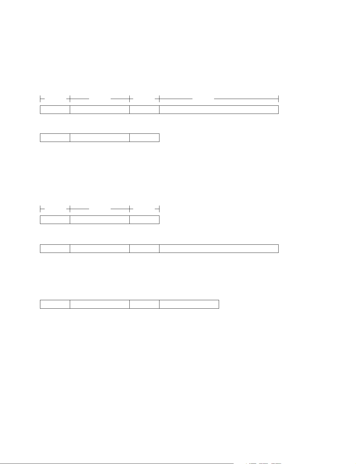
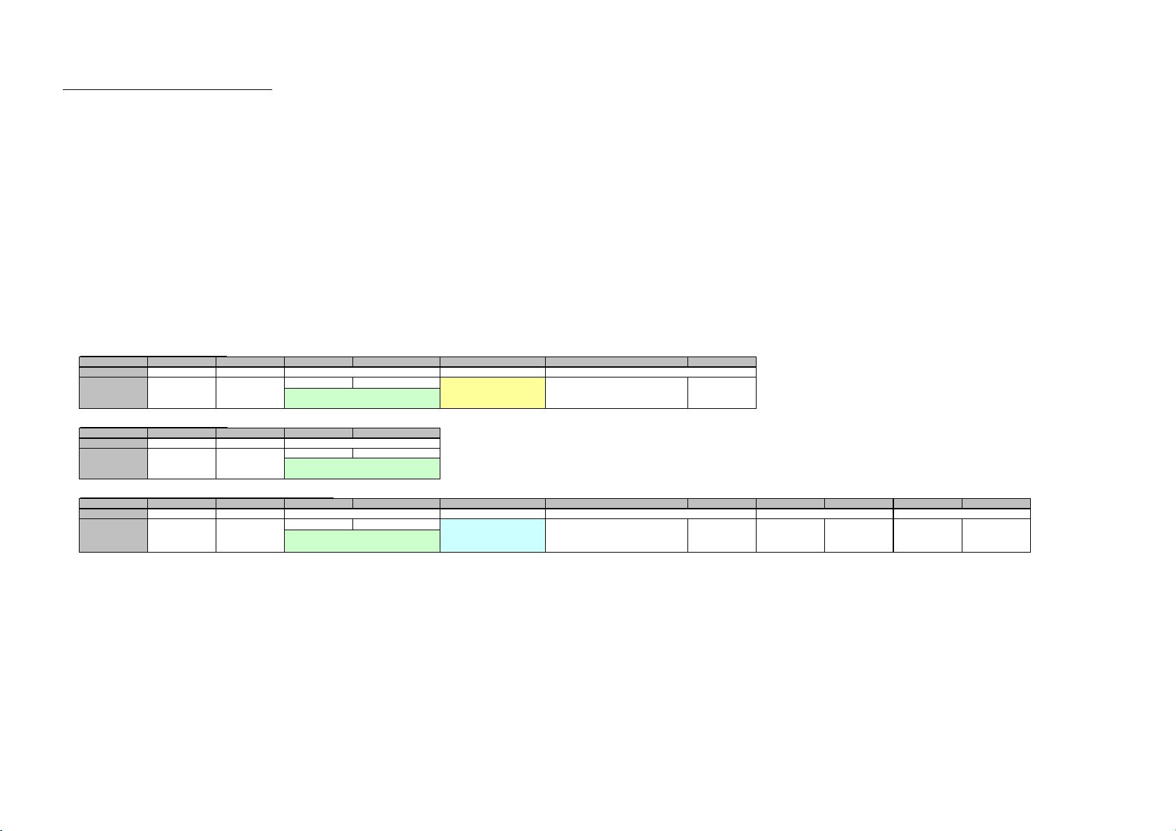
3-4-1-4. SET Request
The SET request is used to set a new value in the specified item. Details of the request and the response
are described below.
Request
Request
SET (00h) Item No. n Set Data (n byte)
Item No.
Data
Length
Data
Response
OK (01h) Item No. 0
3-4-1-5. GET Request
The GET request is used to acquire the value of the specified item. Details of the request and the response
are described below.
Request
Request
GET (01h) Item No. 0
Item No.
Data
Length
Response
OK (01h) Item No. n Get Data (n byte)
3-4-1-6. ERROR Response
When an error occurs in the contents of a request or in the result of execution, NG is returned as the
response.
NG (00h) Item No. 2 Error Code (16)
Q004-R1
9
Page 11

O
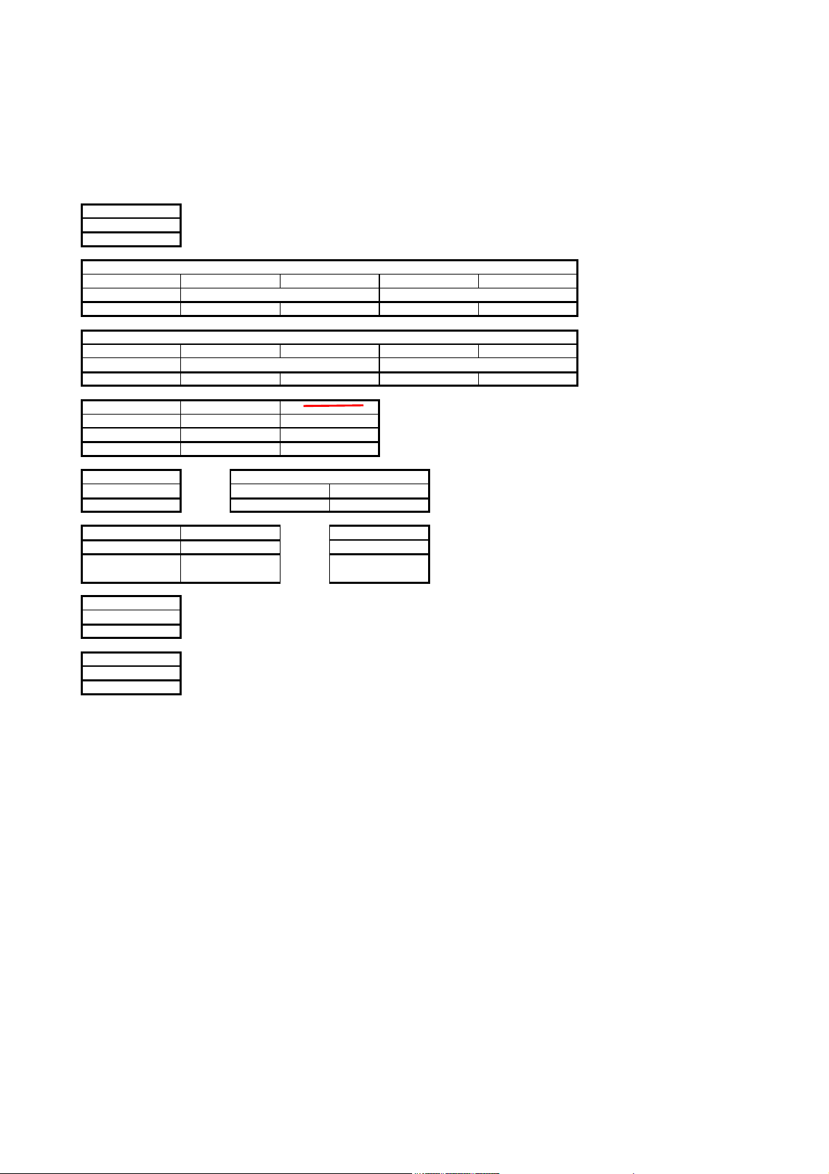
3-4-2. Items
Category Description SET GET
70**h Used to transmit the RS-232C protocol. O
A0**h Used to set or acquire various information of the equipment OO
3-4-2-1. RS-232C Transmission (70**h)
Used to transmit the RS-232C protocol.
Refer to SXRD PROTOCOL APPENDIX_70xxh.xls for data length and data.
Lower byte Description SET GET
00h Command that receives response from RS-232C O
3-4-2-2. Equipment Information Acquisition (A0**h)
Used to set or acquire the information of the equipment (SXRD projector).
Refer to SXRD PROTOCOL APPENDIX_A0xxh.xls for the lower byte, data length and data.
10
Q004-R1
Page 12

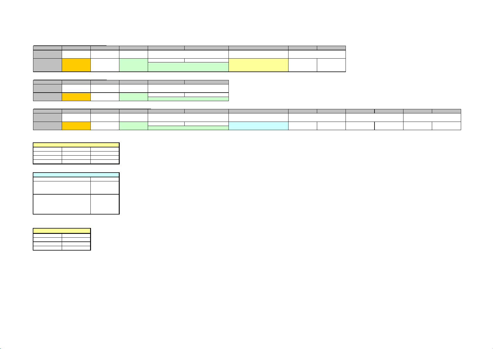
3-4-3. Error Code
The error code list is shown below with a detailed description of each.
Category Error Error Code
Item Error (01**h) Invalid Item 01h
Invalid Item Request 02h
Invalid Length 03h
Invalid Data 04h
Short Data 11h
Not Applicable Item 80h
Community Error (02**h) Different Community 01h
Request Error (10**h) Invalid Version 01h
Invalid Category 02h
Invalid Request 03h
Short Header 11h
Short Community 12h
Short Command 13h
Network Error (20**h) Timeout 01h
Comm Error (F0**h) Timeout 01h
Check Sum Error 10h
Framing Error 20h
Parity Error 30h
Over Run Error 40h
Other Comm Error 50h
Unknown Response F0h
NVRAM Error (F1**h) Read Error 10h
Write Error 20h
Q004-R1
11
Page 13

3-4-3-1. Item Error
This error occurs when the Item No. of a request is illegal or its data is illegal. The conditions for occurrence of the respective errors are shown below.
Invalid Item
An unsupported Item No. is specified.
Example 1: The unsupported category 0xA** is specified.
Example 2: The unsupported Item No. 0x8010 is specified.
Invalid Item Request
The Item No. is supported but an unsupported Request is issued.
Example: An attempt is made to set data in the Model Name (0x8001).
Invalid Length
Data length of the specified Item No. is too long.
Example: An attempt is made to set 25 byte data in the installation location (0x8003).
Invalid Data
Data of the specified Item No. is outside the setting range.
Example: An attempt is made to set 101 in the Item when the setting range of the Item is 1 to 100.
Short Data
The length of data is shorter than the value specified by the data length.
Example: The actual data length is 9 bytes but data length is 10.
Not Applicable Item
An item that is not valid at present is specified.
Example: The item to switch the display is specified when the main power is off.
3-4-3-2. Community Error
This error occurs when community is different.
Example: “ABCD” is specified when “SONY” is set.
12
Q004-R1
Page 14

3-4-3-3. Request Error
This error occurs when header or command is illegal. The conditions of occurrence of the respective
errors are shown below.
Invalid Version
The version of the header is other than 2.
n
When another version is supported, an error occurs in all versions other than the supported version.
Invalid Category
The category does not match.
Example: 0x0B is specified in the device of category = 0x0A.
Invalid Request
An unsupported request is specified.
Example: Request = 0x02 is specified.
Short Header
The received data is 1 byte.
Short Community
The received data is in the range of 2 to 5 bytes.
Short Command
The received data is in the range of 6 to 9 bytes.
3-4-3-4. Network Error
This is an error that occurs in TCP/IP. The conditions of occurrence of the respective errors are shown
below.
Timeout
Communication was interrupted.
Q004-R1
13
Page 15

3-4-3-5. Comm Error
This is an error in communication with the main control microprocessor of the display.
Timeout
Reception data is not returned after data is sent.
Check Sum Error
A check sum error occurred in the main control microprocessor of the display.
Framing Error
A framing error occurred.
Parity Error
A parity error occurred.
Over Run Error
An overrun error occurred.
Other Comm Error
Another error occurred.
Unknown Response
The data cannot be processed was received.
3-4-3-6. NVRAM Error
Read Error
Reading from NVRAM was failed.
Write Error
Writing to NVRAM was failed.
14
Q004-R1
Page 16
Version 0.02
>
A
A
>
A
A
>
]
]
]
A
A
X
Y
e
<Communication Protocol>
Use the following protocol to send data to and receive them from the projector.
The details on CMD1, CMD2, and DATA (written in red) are described in "Communication Commands".
The details on CHECK DATA, DATA LENGTH, and CHECK SUM (written in blue)
are described on this worksheet.
B0
START CODE
5 h
B2B1
Destination (To) INDE
PERIPHERAL INDEX GROUP INDEX DEVICE INDEX
01 h 00 h 01 h
00 h
Source (From) INDEX
PERIPHERAL INDEX GROUP INDEX DEVICE INDEX
03 h 00 h 00 h
CMD[0] CMD[1] CMD[3]
B11 B12 B13
CATEGOR
SET Fixed valu
80 h
CHECK DAT
B14
DATA LENGTH
B15 B16
B16 + 2 00 h Note 1
DATA[1
DATA[2
DATA[N
Bm (= Bn + (N-1))Bn ( = B17) Bn + 1
CHECK SUM
Bm + 1
END CODE
Bm + 2
5A h
B5B4B3
01 h
B10B9B8B7B6
01 h01 h
<About CHECK DATA
The total number of bytes from "DATA 1" to "DATA N" + 2 is assigned here.
s for the "DATA" part, the number of bytes vary depending the command to be sent.
lso, even when the command is the same, the number of bytes in the "DATA" section varies depending on whether the command is "SET" or
For this reason the value here varies depending on the command to be sent.
<About DATA LENGTH
The total number of bytes from "DATA 1" to "DATA N" + 2 is assigned here as in "CHECK DATA".
The difference from "CHECK DATA" is that only "the total number of bytes" is set without 2 added.
<About CHECK SUM>
Sets the checksum.
Checksum can be calculated by
operating "XOR" to the values from "PERIHERAL INDEX(B1)" to "DATA N(Bm)".
<Example of calculation>
5 1010 0101
5A 0101 1010
nswer 1111 1111
<About CMD[0], CMD[1], DATA[1], .........DATA[N]
Refer to the "PjStn2CommCommandTable" sheet.
Page 17
List of All Commands
NO COMMAND NAME
ADJ USER
1
<USER COMMAND>
(ADJ USER NO)
DU USER
2
<USER COMMAND>
(DU USER NO)
SIRCS
3
<USER COMMAND>
Send SIRCS
MEMORY
4
<USER COMMAND>
MEMORY(SAVE/RESET)
ADJ USER MULTI PICS
22
<USER COMMAND>
(ADJ USER NO MULTI)
RS232C
SET 00h 00h Option
GET 01h
REPLY 02h Status
CMD1 CMD2 DATA1 DATA2 DATA3 DATA4 DATA5 DATA6 DATA7 DATA8 DATA9
CMD[0] CMD[1] CMD[2] CMD[3] CMD[4] CMD[5] CMD[6] CMD[7] CMD[8] CMD[9] CMD[10]
ADJ USER NO
ADJ USER NO
ADJ USER NO
ACK(232C) 03h ACK/NAK DATA
SET 01h 00h DATA SIZE DATA
GET 01h DATA SIZE
REPLY 02h DATA SIZE DATA
DU USER NO
DU USER NO
DU USER NO
ACK(232C) 03h ACK/NAK DATA
SET 17h 00h SIRCS CODE REPEAT
CATEGORY REPEAT NUMBER
REQUEST 00h SAVE/RESET MEMORY NO INPUT
03h
ACK(232C) 03h ACK/NAK DATA
SET 20h 00h INPUT Option
GET 01h INPUT
REPLY 02h INPUT Status
ADJ USER NO DATA
ADJ USER NO
ADJ USER NO Lower
ACK(232C) 03h INPUT ACK/NAK DATA
DATA
Lower
ADJ USER NO
∼
CMD[4+n]
DATAUpper
∼∼∼∼∼∼
∼∼∼∼∼∼
Data[n-1]
Data[n-1]
Upper DATA
Item Number Data
Item Name Data Upper Byte Lower Byte
ACK 00h 00h
NAK
Undefined
Command
Size Error 04h
Select Error 05h
Range Over 06h
Not Applicable 0Ah
Check Sum
Error
Framing Error 20h
Parity Error 30h
Over Rub Error 40h
Other Comm
Error
01h
F0h
01h
10h
50h
Page 18
1.About ADJ USER NO and ADJ USER NO MULT
I
r
A
A
(1)ADJ SET command
Sets an adjustment value.
"ADJ REPLY data" returns when "ADJ SET" is executed.
(2) ADJ GET command
Acquires an adjustment value.
Response to the "Get adjustment value of ADJ item" command (ADJ REPLY data) returns when "ADJ GET" is executed.
(3) ADJ REPLY command
Response to the "Get adjustment value of ADJ item" command
(4) How to use the ADJ STATUS flag (ADJ REPLY: CMD[4])
(a) When the ADJ Status flag is "00h"
Since this is a normal adjustment value, set the adjustment item using the value of "ADJ DATA".
(b) When the ADJ Status flag is "01h"
Since this is an adjustment item error (the adjustment value of this item cannot be set), the adjustment item of Projector Station is masked
(displayed in gray).
(c) When the ADJ Status flag is "02h"
Check that the value of "ADJ DATA" is "ADJ Lower" (the minimum value of the adjustment value) or larger and "ADJ Upper" (the maximum value of the adjustment value) or lower,
and set the adjustment item using the value of this "ADJ DATA".
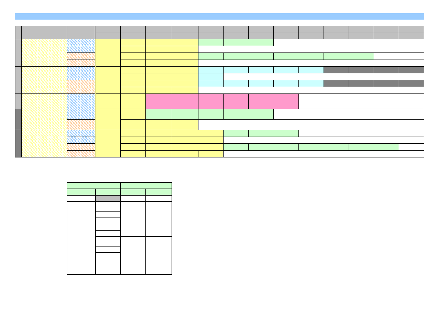
1. Access to the ADJ USER items
Set adjustment value of ADJ USER item
CMD Number CMD[0] CMD[1] CMD[2] CMD[3] CMD[4] CMD[5] CMD[6]
Function ADJ USER SET Option
Value
Get adjustment value of ADJ USER item
CMD Number CMD[0] CMD[1] CMD[2] CMD[3]
Function ADJ USER GET
00h 00h
00hValue 01h
ADJ USER NO DAT
MSB LSB
Refer to [ADJ USER NO List]
ADJ USER NO
MSB LSB
Refer to [ADJ USER NO List]
Refer to [OPTION List] MSB LSB
Response to the "Get adjustment value of ADJ USER item" command
CMD Number CMD[0] CMD[1] CMD[2] CMD[3] CMD[4] CMD[5] CMD[6] CMD[7] CMD[8] CMD[9] CMD[10]
Function ADJ USER REPLY Status
Value 00h 02h
ADJ USER NO DAT
MSB LSB
Refer to [ADJ USER NO List]
Refer to [Status List]
Lower
MSB LSB
Uppe
MSB LSBMSB LSB
Page 19
22. Access to the ADJ USER MULTI PICS items(SRX-001 multi-screen supported)
r
]
]
]
]
]
]
]
]
R
]
]
]
]
]
R
]
]
]
]
]
]
]
]
]
]
]
]
R
T
T
y
Set adjustment value of ADJ USER MULTI item
CMD Numbe
Function
Value 20h
Get adjustment value of ADJ USER MULTI item
CMD Number CMD[0
Function
Response to the "Get adjustment value of ADJ USER MULTI item" command
CMD Number CMD[0
Function
Value LSB
CMD[0
ADJ USE
MULTI PICS
ADJ USE
MULTI PICS
20h 01hValue
ADJ USE
MULTI PICS
20h
CMD[1
SET INPUT Option
CMD[1
GET INPUT
CMD[1
REPLY INPUT Status
02h
CMD[2
Refer to [INPUT
List]
CMD[2
Refer to [INPU
List]
CMD[2
Refer to [INPU
List]
CMD[3
MSB LSB
Refer to [ADJ USER NO List]
CMD[2
ADJ USER NO
MSB LSB
Refer to [ADJ USER NO List]
CMD[2
ADJ USER NO
MSB LSB
Refer to [ADJ USER NO List]
CMD[4
CMD[3
CMD[3
CMD[5
Refer to [OPTION List]00h
CMD[4
CMD[6
CMD[5
CMD[7
DATAADJ USER NO
LSBMSB
CMD[6
CMD[7
CMD[8
LSB MSBLSB MSBRefer to [Status List] MSB
CMD[9
CMD[10
DATAUpperLower
[OPTION List]
No Function Do nothing 00h
Relative Relative value 01h
Absolute Absolute value 02h
Reset Reset 03h
[Status List]
Complete successfull
Adjustment item ERROR
(Cannot be adjusted by the
currentinput signal and power mode)
Adjustment value ERROR
(OutOfRenge)
(The setting value is out of the
adjustment range.)
[INPUT List]
Input 1 bit0
Input 2 bit1
Input 3 bit2
Input 4 bit3 INPUT's bitOR can be used only for SET
INPUT
Option
Status
00h
01h
02h
Page 20
[ADJ USER NO List] [ADJ USER NO MULTI List]
K
L
2bit
e
V
A
V
ADJ USER NO
Picture Mode 02h
function1 00h Contrast 10h
function2 01h Brightness 11h
function3 02h Color 12h
Screen Control 05h Hue 13h
PICTUREMUTING 30h
Screen1 ON 01h 6500
Screen2 ON 02h custom1 01h
Screen3 ON 04h custom2 02h
Screen4 ON 08h
Input-1 Signal Sel 32h
Input-2 Signal Sel 33h
Input-3 Signal Sel 34h
Input-4 Signal Sel 35h
Cinema_PSF 3ch
TESTPATTERN 3dh
LCD_Contrast 3eh H_Size_OFFSET 57h
Pattern 1 01h V_Shift 55h
Pattern 2 02h Dot Phase_No 56h
LAMP MODE 40h
Lamp Select 41h DUAL 00h
reserved 02h
reserved 03h
INSTALLATION 43h
ALUE
2BYTE data (See Note1)
Off 00h Sharpness 14h
ColTemp 17h
RGB 00h
YCbCr 01h
YPbPr 02h DCDM 00h
RGB 00h 709 01h
YCbCr 01h CIEXYZ 02h
YPbPr 02h Reserved 03h
RGB 00h Off 00h
YCbCr 01h Gamma 1.8 01h
YPbPr 02h Reserved 02h
RGB 00h Gamma 2.2 03h
YCbCr 01h Reserved 04h
YPbPr 02h Gamma 2.6 05h
Off 00h OFF 00h
On 01h ON 01h
Off 00h H_Shift 54h
Color Space 1ch
Gamma Correction 22h
OSD 3Ah
00h to 4Bh (0 to 75)
100% 00h GAINRED 80h
93% 01h GAINGREEN 81h
86% 02h GAINBLUE 82h
79% 03h BIASRED 83h
72% 04h BIASGREEN 84h
65% 05h BIASBLUE 85h
58% 06h
51% 07h
SINGLE 01h
FRONT 00h
REAR 01h
DJ USER NO MULTI
ALUE
00h to 64h (0 to 100)
00h to 64h (0 to 100)
00h to 64h (0 to 100)
00h to 64h (0 to 100)
00h to 64h (0 to 100)
∆
∆
∆
0 to 300
0 to 100
00 to 63
-50 to 50
00h to 64h (0 to 100)
00h to 64h (0 to 100)
00h to 64h (0 to 100)
00h to 80h (0 to 128)
00h to 80h (0 to 128)
00h to 80h (0 to 128)
00h
03h
04h
05h
Note 1 bit7 bit6 bit5 bit4 bit3 bit2 bit1 bit0
Upper 8 bits Screen Mode
00h 1 picture 00h INPUT 1 INPUT 1 INPUT 1 INPUT 1
01h 2 picture 01h INPUT 2 INPUT 2 INPUT 2 INPUT 2
02h reserved (3) 02h INPUT 3 INPUT 3 INPUT 3 INPUT 3
03h 4 picture 03h INPUT 4 INPUT 4 INPUT 4 INPUT 4
ower
valu
Screen4 INPUT Screen3 INPUT Screen2 INPUT Screen1 INPUT
Page 21
In SRX-001
Ο
Ο
Ο
Ο
Ο
Ο
C
)
[ADJ USER NO List] New
Screen Mode 03h 00h 1 picture Screens
is used in ADJ USER(00)
is used in ADJ USER MULTI PICS(20)
01h 2 picture
02h reserved (3)
03h 4 picture
Screen 04h bit0 Screen1 Screen selection
LAMP MODE B 42h
VREFHIRED 86h
VREFHIGREEN 87h
VREFHIBLUE 88h
DevRefreshOff 89h 00h ON DEVICE REFRESH OFF
00h to FFh (0 to 255)
00h to FFh (0 to 255)
00h to FFh (0 to 255)
InterPol 8ah 00h OFF Processing between QDI assistant
VCOMRED 8bh
VCOMGREEN 8ch
VCOMBLUE 8dh
Upper 4bit Color Lower 4bit PATTERN
bit0 Blue 0 Nothing (un-displaying)
bit1 Green 1
bit2 Red 2 Crossing hatch (Invert)
00h to FFh (0 to 255)
00h to FFh (0 to 255)
00h to FFh (0 to 255)
bit1 Screen2
bit2 Screen3
bit3 Screen4
bit7 ScreenALL
Refer to LAMPMODE (40h).
01h OFF
01h ON
rossing hatch (Normal
Page 22

2.DU USER
q
y
[0]
]
]
]
]
E
)
[0]
]
]
]
]
]
]
]
]
E
]
]
]
]
A
l
R
A
r
A
r
A
n
A
r
A
D
A
n
A
s
T
A
e
R
A
g
L
A
A
y
A
y
A
)
n
A
n
r
A
e
A
e
A
n
A
n
e
A
s
A
n
(2) When DU USER GET is executed
Data is ac
When "DU GET" is performed, the response to the "Get adjustment value of the DU item" command (DU REPLY data) returns.
(3) About DU USER REPLY
Response to the "Get data from the shared memory" command
2.DU USER
uired from the shared memor
Get data of desired size from desired address in the shared memory
CMD Number
Fuction DU USER GET DATA SIZ
Value 01h 01h MSB LSB n(Max=16
Response to the "Get data of desired size from desired address in the shared memory" command
CMD Number
Fuction DU USER REPLY DATA SIZ
Value 01h 02h
CMD
CMD
CMD[1
CMD[1
CMD[2
DU USER NO
CMD[2
DU USER NO
MSB LSB
Refer to [DU USER NO List]
CMD[3
CMD[3
CMD[4
CMD[4
n(Max=16)
CMD[5
Data[0
CMD[6
Data[1
CMD[7
Data[2
CMD[8
Data[3
DU USER NO
Command Name
STATUS ERROR
STATUS POWER
CONTROL MODE SEL
LAMP TIME WARNING
INPUT SIGNA
FH
FV
ORIGNAL STATUS NO
RESOLUTION
SET TIME
LAMP TIME
ROM VERSION
Lamp Time Countdow
FPGA VERSION
FPGA VERSION2
FPGA VERSION3
BOARD ID
LAMP_STATUS
LENS_SENSOR_STATUS
TIMER RESE
FPGA VERSION4
SHUTTER_STATUS
Model Numbe
Model Name
Sirial Numbe
SCREEN_INPUTCH
VALUE
0x01
0x02
0x05
0x08
0x09
0x0A
0x0B
0x0E
0x0F
0x12
0x13
0x1D
0x24
0x27
0x28
0x29
0x2A
0x2B
0x2C
0x2D
0x2E
0x2F
0x31
0x33
0x34 Acquire serial number
0x36
cquire the reason why the equipment fe
cquire POWER MODE
CONTROL MODE
cquire lamp timer warnin
cquire current input signa
cquire H Frequenc
cquire V Frequenc
cquire the original status numbe
cquire resolutio
cquire equipment use tim
cquire lamp use tim
cquire the main software versio
Count down to the lamp available tim
cquire model numbe
cquire model name (16-byte ASCII code
Acquire input channel for 4 screen quadrants
Description
cquire the FPGA software versio
cquire the FPGA software versio
cquire the FPGA software versio
cquire input signal board I
cquire lamp illumination statu
cquire the lens sensor valu
Reset timers
cquire the FPGA software versio
cquire the shutter statu
Page 23

[
DU USER NO List
]
y
y
g
h
j
e
RESO_1080_48I
R
Y
1080_48I
_
Y
_CH_
/
&
E
DU USER NO
STATUSERROR
STATUSPOWER
CONTROLMODESEL
LAMPTIMEWARNING
INPUTSIGNAL
ORIGNAL_STATUSNO
RESOLUTION
SETTIME
LAMPTIMER
ROM_VERSION
FH
FV
VALUE REPLY DATA
01h 6Byte
02h
05h
08h
09h
0Ah 2Byte
NO ERROR
STANBY
START UP
STARTUP LAMP
POWER ON
COOLING1
COOLING2
SAVING COOLING1
SAVING COOLING2
SAVING STAB
USER
SERVICE
SPSERVICE
MATSUDAA
FACTORY
NORMALIT
LAMP_A TIME WARNING
LAMP_B TIME WARNING
LAMP
AB TIME WARNING
RGB1024X768
RGB1280X960
RGB1280X1024
RGB1600X1200
RGB_HDTV
YUV_15K
YUV_30K
YPBPR_HDTV
VIDEO_CH_NOINPUT
INPUT_CH_NOINPUT
INPUT
UNKNOWN
FH
See Note 1
0x00
0x01
0x02
0x03
0x04
0x05
0x06
0x07
0x08
0x00
0x01
0x02
0x03
0x04
0x00
0x01
0x02
0x03
0x0E
0x11
0x12
0x13
0x16
0x17
0x18
0x1A
0x1B
0x1C
0x1D
Eg. 31.5[kHz]: 0x0C4B
DATA SIZE
EACH
DATA FORM
TOTAL DATA SIZ
INPUT1/INPUT2/INP
UT3/INPUT4
0Bh 2Byte
0Eh
0Fh
12h 4B
13h 2Byte
1Dh 2B
MAIN SOFT ROM VERSION
FV
NOINPUT
480/60i
575/50i
1080/60i
1024X768_VESA60
1024X768_VESA70
1024X768_VESA75
1024X768_VESA85
1280X960_VESA60
1280X1024_VESA60
1280X1024_VESA75
1280X1024_VESA85
1600x1200_VESA60
480_60P
475_50P
1080_50I
720_60P
720_50P
RESO_15K60
RESO_15K50
RESO_HDTV
RESO_1024X768
RESO_1280X960
RESO_1280X1024
RESO_1600X1200
RESO_480_60P
RESO_575_50P
RESO_1080I_50I
RESO_720_60P
RESO_720_50P
USE TIME
USE TIME
Eg. 59.9[Hz]: 0x176A
0x00
0x03
0x04
0x05
0x17
0x18
0x19
0x1A
0x20
0x24
0x25
0x26
0x27
0x2B
0x2C
0x2D
0x2F
0x30
0x31
0x02
0x03
0x04
0x0A
0x0D
0x0E
0x0F
0x10
0x11
0x12
0x14
0x15
0x16
ned 2-byte value: unit
Unsi
Unsigned 2-byte value: unit h
Ma
or 1Byte Minor 1Byt
1Byte
1Byte
INPUT1/INPUT2/INP
UT3/INPUT4
INPUT1/INPUT2/INP
UT3/INPUT4
INPUT1/INPUT2/INP
UT3/INPUT4
LAMP_A/LAMP_B
1Byte
1Byte
1Byte
8Byte
8Byte
4Byte
4Byte
4Byte
te
te
Page 24

y
p
n
T
r
y
y
y
T
y
y
y
y
y
y
y
y
y
A
w
(
)
p
)
r
r
g
e
A
h
t
Lamp Timer Countdown
e
e
g
16Byte
p A
24h
FPGA_VERSION1
FPGA_VERSION2
FPGA_VERSION3
BOARD_ID
28h
29h VERSION Major 1Byte Minor 1Byte
2Ah
LAMP_STATUS 2Bh
LENS_SENSOR_STATUS
2Ch
TIMER RESET 2Dh
FPGA_VERSION4 2Eh
SHUTTER STATUS 2Fh
Model Number
Model Name
Sirial Numbe
31h
33h 16Byte
34h 4B
SCREEN_INPUTCH 36h 1Byte
No warnin
XX to lamp available tim
XX to lamp available tim
VERSION
VERSION
VIF board
HIF board
reserved
reserved
NO BOARD
LAMP AB ON
reserved
LAMP A ON
LAMP B ON
LAMP OFF
ssign 8 sensor values to eac
bi
Lam
Lamp B
reserved
VERSION Major 1Byte Minor 1Byte
Closed
mute ON
en (mute OFF
O
Unkno
Reserved
Model name
Serial numbe
INPUT 1
INPUT 2
INPUT 3
0x00
0x01
0x02
Major 1Byte Minor 1Byte27h
Major 1Byte Minor 1Byte
0x00
0x01
0x02
0x03
0x07
0x00
0x01
0x02
0x03
0xFF
See Note 2
0x00
0x01
0x02
0x00
0x01
0x00
0x01
SCII code
ned 4-byte valu
Unsi
0x00
0x01
0x02
INPUT 4 0x03
1Byte
2Byte
LAMP_A/LAMP_B
16Byte
PR1_QDI/PR1_VSA/
2Byte
PR2_QDI/PR2_VSA/
PR3_QDI/PR3_VSA/
PR4_QDI/PR4_VSA
LPD TG/MX IN
UPPER/MX IN
2Byte
LOWER/RESERVE
D/RESERVED/RES
ERVED/RESERVED
/RESERVED
16Byte
IFA CSC/IFB
2Byte
CSC/IFC CSC/IFD
CSC/RESERVED/R
ESERVED/RESERV
ED/RESERVED
1Byte 4Byte
1Byte
1Byte
1Byte
16Byte
HIFA_HDSDIC/HIFB
2Byte
_HDSDIC/HIFC_HD
SDIC/HIFD_HDSDIC
/HIFA_HDSDIM/HIF
B_HDSDIM/HIFC_H
DSDIM/HIFD_HDSD
1Byte
1Byte
4Byte
SCREEN1/SCREEN
2/SCREEN3/SCREE
N4
te
Note 1
LSB
tio
PWR PROT 24V PROT FAN1 LAMPA OPT UNI
PWR PROT 16V PROT FAN2 LAMPB LAMPA TEMP BallastB Erro
PWR PROT dummyFAN3 T_Prism LAMPB TEMP LAMPA dumm
PWR PROT dummyFAN4 BallastALAMPA DOOR LAMPB dumm
PWR PROT
Error descri
PWR PROT
MSB
Note 2
LSB SHUTTER Open
PWR PROT dumm
PWR PROT dumm
SHUTTER Close
MSB SHIFT +
1BYTE 2BYTE 3BYTE 4BYTE 5BYTE 6BYTE
PR1
PR2
ZOOM S
ZOOM L
FOCUS F
FOCUS N
SHIFT -
B_DET FAN5 BallastB LAMPB DOOR CPU ERROR
dummy
:SENSOR OFF
L:SENSOR ON
FAN6
OPT UNI
FAN7 PR-284 dumm
dumm
REAR COVER
dumm
BallastA ErrorFAN8 HIF
dumm
FAN10
SHUTTER
OPENNING
dumm
dumm
REAR CT
dummy
dumm
dumm
Page 25

3.Sending SIRCS
W
[
]
W
>
>
S
K
E
P
E
S
T
Y
Y
(1) About SIRCS SE
It only sends SIRCS.
At this time, "SIRCS REPLY data" does not return.
Set SIRCS CODE
CMD Number
Function
Value
[CATEGORY List]
CATEGOR
15-bit length
20-bit length
REPEAT List
REPEAT S
00h
01h
CMD[0] CMD[1] CMD[5] CMD[6] CMD[7]
SIRCS SET
17h 00h
VALUE
4054h
855Ah
REPEA
Equivalent to when SircsCode is sent singularly (the remote controller pressed once).
REPEAT NUMBER is invalid at this time.
Equivalent to when SircsCode is generated consecutively (the remote controller pressed
consecutively), as if it was pressed as much as the number of times of REPEAT NUMBER.
Operation
CMD[2]
MSB
CMD[3]
LSB
CMD[4]
SIRCS CODE
Refer to [CATEGOR
List]
REPEAT NUMBERCATEGORY
EPEAT S
0/1 MSB LSB
Refer to [REPEAT List]Refer to [SIRCS CODE List]
<SIRCS CODE List>
<15BIT CATEGORY
0x
1x
2x
3x
4x
5x
6x
INPUT D
7x
<20BIT CATEGORY
x0 x1 x2 x3 x4 x5 x6
0x
1x
2x
3x
4x
5x
6x
7x
is the command to be used this time.
SHARPN
SHARPN
SS-
SOFT
SHUTTER
MUTING
SS+
SHAR
Screen1 Screen2 Screen3 Screen4
LENS
LENS
FOCUS F FOCUS N ZOOM L ZOOM S
SHIFT ↓
VIDEO
MEMORY
3
VIDEO
MEMORY
1
SHIFT ↑
VIDEO
MEMORY
2
CONTRAS
T+
HIGH
CONTRAS
T-
LOW
Screens
xA xB xC xDx6 x7 x8 x9x0 x1 x2 x3 x4 x5
COLOR+
HIGH
VIDEO
(INPUT1)
COLOR-
LOW
INPUT A
(INPUT2)
xB xC xD xEx7 x8 x9 xA
INPUT B
(INPUT3)
xE xF
BRITNES
+
BRIGHT
POWER
ON
BRITNES
-
DAR
POWER
OFF
INPUT C
(INPUT4)
xF
KEY UP
Note 1) The motor starts to move when the LENS SHIFT, FOCUS, and ZOOM commands are set. Set KEY UP to stop it.
Page 26

4.MEMORY(SAVE/RESET) Proces
s
[0]
]
]
]
]
]
]
Y
A
(
)
A
(
)
(0)
[
]
T
d
A
d
Memory Save/Reset Request Commands
CMD Number
Fuction MEMORY
Value 03h 00h
CMD
CMD[1
MEMOR
REQUEST
CMD[2
SAVE/RESET MEMORY NO INPUT
SAVE(1)???
RESET
CMD[3
Refer to
MEMORY NO
CMD[4
Refer to [INPUT
List
CMD[5
DJ USER NO
UPPER byte
CMD[6
DJ USER NO
LOWER byte
ADJ USER NO
dummy dummy
[MEMORY NO List]
MEMORY NO VALUE
CH 1
ST_USER 2
SET_USER 3 × ×
WB_ALL 4 × ×
WB_1 5 × ×
WB_2 6 × ×
reserved 7 × ×
reserved 8 × ×
reserved 9 × ×
reserved A × ×
[INPUT List]
INPUT
Input 1 bit0
Input 2 bit1
Input 3 bit2
Input 4 bit3
INPU
parameter
valid/invali
Ο
Ο
INPUT's bitOR can be used
DJ USER NO
parameter
valid/invali
×
×
Page 27

Setup Screen Items and Their Descriptions
y
/
The basic specifications of the setup screen and setting data is those of Qualia's Web screen.
SRX001 may include items that are not .
SRX001 contain data whose size should be changed, but basically it is written in Qualia's specifications.
SRX001 ma
The item number of the data or data size are subject to additions and changes.
require some items to be added but they are not added here
PJ Talk
The commands that already exist in the SDCP v2 specifications are used as they are.
The communication commands are invented in response to the new PJ Talk category 0xA0**.
They can be assigned to 0x90**. It actually is an addition to 0x90**.
ver(1) category(1) community(4)
0x02 0x0A SONY
Request
Response(1
SET/GET
OK/NG
Item No.(2)
0xA0 ID Variable Variable
For the ID, refer to:
It corresponds to the ID No. in column A of the EEPROM control table.
Response
Responses to SET command
OK 0xA0 ID 0
Responses to GET command
OK 0xA0 ID Length Data(n)
About error responses
Based on the SDCP v2 protocol
Setup screen
The WEB Setup screens are posted for your reference.
The parameter numbers (parameter names) of the setting item are indicated on the right side of the screen.
The conditions for checking errors of the item's data and error messages are indicated below the screen.
Owner Information
Date & Time
Network
Password
Mail Report
Advertisement
PJ Talk
SNMP
Update
Reboot
Information
Length(1) Data(n)
EEPROM control table!A1
Page 28

Parameter
y
0
p
e
n
m
This is the list of the number of item data, the number of data bytes, links to data contents, and setup screens.
The number is shown in the lower bytes of the command number in the SET/GET commands.
The number is subject to change.
You can identif
the details of the data by referring to the links
Parameter List
IDAscendingOrder
Other sheets
Details on data contents
Special commands
The data of the items provided so far are the ones that simply sets or gets data,
but other than those commands, there are commands that need to be provided as well.
Reboot request
Command that resets and starts NS752
Update mode request
Command that moves NS7520 into the u
date mod
Test mail request
Sends a test mail by using the setting content of the mail report.
Should the result of the sent mail be returned synchronously or asynchronously?
Currently it is synchronous. The time when responses are given is unknown. It depends on the enviro
←
Maintenance reference time reset request
Command that sets the maintenance reference time in the mail report to the set timer of that time.
Make it asynchronous.
In response to the test mail send request, whether the request was accepted,
or not accepted because the line is busy, is returned.
"Test mail has been sent" (normally/abnormally ended) is acquired by the Get progress co
Mail body view
Command to check a mail body
←
Delete
The mail body may be longer than the maximum packet length of SDCP v2.
Is this function necessary?
Get information error
There are errors that NS7520 detects other than the ones that H8 detects.
Page 29

Checking errors in the SDCP data
g
n
2
y
a
g
y.
s
When the data of illegal format is set (For example when you try to set 99 in Month) the error check is not required at the SDCP level.
On the communication protocol, it is possible to return the error response: Invalid Data and to discard the value.
In the case of QUALIA (HTTP), we have thought that no illegal value would be transmitted
when performing an error check with the browser’s script, but when setting it with SDCP,
should we perform error checks for all the items by using SDCP?
If so, the error check that has been performed with a script should also be available in NS7520.
About endian
NS7520 is bi-endian but is set as bi
Big endian is when 0x1234 is placed as 0x12/0x34 with the smaller address first, and little-endian is when it is placed as 0x34/0x1
About boader adjustment of the structure members
Different alignment is specified in each individual structure. Refer to the boarder adjustment values that are described on the description sheet of each structure.
The treatment of the string-form data in the 0xA0** command group
A NULL terminal s
Therefore, the length of string data can be set from 0 up to the maximum number of bytes
For other data formats, an error occurs unless the designated data length is kept. (Invalid Data Length)
When data len
Generally, the string-type information stipulates a large maximum size, but the actual value is shorter than the stipulated number of character
Only the string-type data receives a special treatment since no unnecessary data are communicated.
About the 0xA0C* commands
Write data to EEPROM by Set command of each data item.
But this merely enables the setting next time the power is turned on.
If you want to enable the setting right after it is set, send the "0xA0C* Apply" command.
mbol is not included (though it's OK to include it). The NULL terminal symbol is added at the receiver of the dat
th is 0, it means the string is empt
-endian. Since Intel's family of CPUs is little-endian, the PC and NS7520 have different endia
Error check is also performed on a GUI application, but since SDCP is disclosed,
←
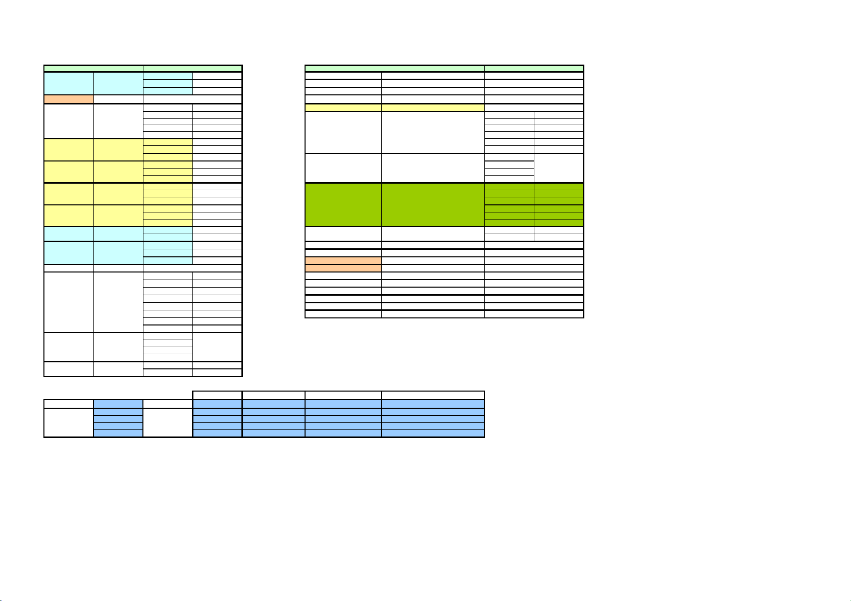
Page 30

Category
Owner
Information
Date & Time
Password
Mail Report
No.
Description SET GET Link
Data
0x00-0x0f
0x10 Owner name 0x20 0x20
0x11 Organization name 0x20 0x20
0x12 Installation location 0x18 0x18
0x13 Lens type 0x01 0x01
0x14 Note 0x80 0x80
0x15-0x1f
0x20 Time zone 0x01 0x01
0x21 Summer time adjustment ON/OFF 0x01 0x01
0x22 Date 0x03 0x03
0x23 Time zone 0x02 0x02
0x24 NTP server name 0x40 0x40
0x25-0x2f
0x30 Administrator password 0x08 0x08
0x31 User name 0x10 0x10
0x32 User password 0x08 0x08
0x33-0x3f
0x40-0x42
0x43 Lamp notification time 0x02 0x02
0x44 Maintenance notification time 0x04 0x04
0x45 Maintenance reference time 0x04 0x04
0x46 Mail address 0x40 0x40
0x47 Mail address 0x40 0x40
0x48 Mail address 0x40 0x40
0x49 Mail address 0x40 0x40
0x4a Report timing (To) 0x01 0x01
0x4b Report timing (Cc) 0x01 0x01
0x4c Mail format 0x01 0x01
0x4d Mail account (sender mail) 0x40 0x40
0x4e SMTP server name 0x40 0x40
0x4f Authentication ON/OFF 0x01 0x01
0x50 Authentication type 0x01 0x01
0x51 POP3 server name 0x40 0x40
0x52 POP account name (login name) 0x40 0x40
0x53 POP password 0x20 0x20
0x54 SMTP account name (login name) 0x40 0x40
0x55 SMTP password 0x20 0x20
0x56 Maintenance elapsed hours × 0x04
0x57-0x5f
CharString!A1 Owner!G4
CharString!A1 Owner!G5
CharString!A1 Owner!G9 Information!J5
LENS!B3 Owner!G11
CharString!A1 Owner!G15
TZONE!B3 Date!D3
ONOFF!B3 Date!D5
Calendar!B3 Date!D9 Information!J23
Calendar!B3 Date!D10 Information!K23
CharString!A1 Date!D14
CharString!A1 Password!E5
CharString!A1 Password!E10
CharString!A1 Password!E11
lamp!B3 Mail!D14
mainte!B3 Mail!D16
mainte!B3
CharString!A1 Mail!D24
CharString!A1 Mail!D25
CharString!A1 Mail!D26
CharString!A1 Mail!D27
Report!B3 Mail!D28
Report!B3 Mail!D29
Format!B3 Mail!D32
CharString!A1 Mail!D38
CharString!A1 Mail!D40
ONOFF!B3 Mail!D42
AuthType!B3 Mail!D44
CharString!A1 Mail!D46
CharString!A1 Mail!D48
CharString!A1 Mail!D49
CharString!A1 Mail!D52
CharString!A1
mainte!B3 Mail!D18
Page 31

o
s
o
s
SNMP
Network
SDAP
&
Pjtalk
Info
Log
Apply
0x60 Contact destination 0x30 0x30
0x61 Contact person 0x30 0x30
0x62 Contact place 0x30 0x30
0x63 Community name 0x09 0x09
0x64 Access right 0x01 0x01
0x65
Tra destination IP address (for 4 addresses
0x10 0x10
0x66 Community name 0x09 0x09
0x67 Access right 0x01 0x01
0x68
Trap destination IP address (for 4 addresse
0x10 0x10
0x69 Community name 0x09 0x09
0x6a Access right 0x01 0x01
0x6b
Trap destination IP address (for 4 addresse
0x10 0x10
0x6c Authenticated trap ON/OFF 0x01 0x01
0x6d Number of hosts to be authorized 0x01 0x01
0x6e
IP address of host to be authorized (for 4 h
0x10 0x10
0x6f-0x7f
0x80 MAC address (Flash memory) × 0x06
0x81 Ethernet speed 0x01 0x01
0x82 DHCP ON/OFF 0x01 0x01
0x83 IP address 0x04 0x04
0x84 Subnet mask 0x04 0x04
0x85 Gateway 0x04 0x04
0x86 DNS1 IP address 0x04 0x04
0x87 DNS2 IP address 0x04 0x04
0x88-0x8f
0x90 SDAP Enable/Disable 0x01 0x01
0x91 SDAP port number 0x02 0x02
0x92 SDAP send cycle 0x02 0x02
0x93 Number of SDAP receivers 0x01 0x01
0x94
SDAP destination IP address (for 4 addres
0x10 0x10
0x95 PJTALK Enable/Disable 0x01 0x01
0x96 Port number 0x02 0x02
0x97 SDCP Timeout 0x02 0x02
0x98 Number of hosts to be authorized 0x01 0x01
0x99
IP address of host to be authorized (for 4 h
0x10 0x10
0x9a Community name (SDCP/SDAP commo0x04 0x04
0x9b-0x9f
0xa0 NS7520 version number × 0x04
0xa1 Acquire current error × 0x06
0xa2 SY CPLD version number × 0x02
0xa3-0xaf
0xb0 Lamp Timer Reset Log × 0x60
0xb1 Error Log × 0xa4
0xb2 Mail Report Log × 0x7d
0xb3-0xbf
0xc0 Update owner information 0x01 ×
0xc1 Update date & time 0x01 ×
0xc5 Update password 0x01 ×
0xc6 Update Network 0x01 ×
0xc7 Update SDAP 0x01 ×
0xc8 Update PJTALK 0x01 ×
0xc9 Update mail report 0x01 ×
0xca Update SNMP 0x01 ×
0xc2 Reboot command 0x06 ×
0xc3 Flash Write command 0x06 ×
0xc4 Acquire test mail send state × 0x02
0xcb Set LCD Contrast adjustment display 0x01 ×
0xcc-0xcf
0xd0-0xff
CharString!A1
CharString!A1
CharString!A1
CharString!A1 SNMP!E4
Access!B3 SNMP!E5
IPADDR!B3 SNMP!E6
CharString!A1 SNMP!E7
IPADDR!B3 SNMP!E8
IPADDR!B3 SNMP!E9
CharString!A1 SNMP!E10
IPADDR!B3 SNMP!E11
IPADDR!B3 SNMP!E12
ONOFF!A1 SNMP!E19
Host!B3 SNMP!E22
IPADDR!B3 SNMP!E23
MAC!B3 Network!D16 Information!J18
SPEED!B3 Network!D17 Information!J19
ONOFF!B3 Network!D4 Information!J12
IPADDR!B3 Network!D6 Information!J13
IPADDR!B3 Network!D7 Information!J14
IPADDR!B3 Network!D9 Information!J15
IPADDR!B3 Network!D10 Information!J16
IPADDR!B3 Network!D11 Information!J17
ONOFF!B3 SDAP!D2
Port!B3 SDAP!D5
Interval!B3 SDAP!D6
Host!B3 SDAP!D10
IPADDR!B3 SDAP!D11
ONOFF!B3 PJTALK!D2
Port!B3 PJTALK!D5
Interval!B3 PJTALK!D7
Host!B3 PJTALK!D10
IPADDR!B3 PJTALK!D11
ixCharString!B3SDAP!D4 PJTALK!D4
Ver!B3
ErrorLog!B10 Information!J10
LampRst!B3 Information!J36
ErrorLog!B3 Information!J47
MailLog!B3 Information!J62
Apply!B3 Owner!G21
Apply!B3 Date!D19
Apply!B3 Password!E16
Apply!B14 Network!D20
Apply!B3 SDAP!D16
Apply!B3 PJTALK!D16
Apply!B26 Mail!E18 Mail!D56 Mail!D62
Apply!B3 SNMP!E30
cendingOrder! Reboot!I3
Apply!B37 Update!I3
TestMail!B3
Page 32

Acquired from H8 by 0x8001 or 0x70** command
Acquired from H8 by 0x8001 or 0x70** command
IDAscendingOrder!B6
Acquired from H8 by 0x70** command
IDAscendingOrder!B80
IDAscendingOrder!B60
IDAscendingOrder!B61
IDAscendingOrder!J62
IDAscendingOrder!B63
IDAscendingOrder!B64
IDAscendingOrder!B65
IDAscendingOrder!B58
IDAscendingOrder!B59
IDAscendingOrder!B79
IDAscendingOrder!B12 IDAscendingOrder!B13
Acquired from H8 by 0x70** command
Acquired from H8 by 0x70** command
Acquired from H8 by 0x70** command
Acquired from H8 by 0x70** command
IDAscendingOrder!B82
IDAscendingOrder!B83
IDAscendingOrder!B84
Page 33

Error
g
Name is empty Enter up to 32 characters
anization is emptEnter up to 32 characters
Or
Location is empty Enter up to 24 characters
Memo is empty Enter up to 128 characters
IDAscendingOrder!B4
IDAscendingOrder!B5
IDAscendingOrder!B6
H8 full
IDAscendingOrder!B7
IDAscendingOrder!B8
IDAscendingOrder!B86
Page 34

IDAscendingOrder!B10
g
h
r
IDAscendingOrder!B11
IDAscendingOrder!B12
IDAscendingOrder!B13
IDAscendingOrder!B14
IDAscendingOrder!B87
Error
Regula
expressio
Year is less than 3 Enter a number between 3 and 99
Year is larger than 99
Year is empty
Year is in 3 digits or more
Regular expression /\D{1,3}/
Month is empty Enter a number between 1 and 12
Month is less than 1
Month is larger than 12
Month in 3 digits or more
Regular expression /\D{1,3}/
Day is empty An invalid data was entered.
Day is less than 1
Day is larger than 31
Regular expression /\D{1,3}/
In month 4/6/9/11, day is larger than 30
In month 2 of a leap year, day is larger than 29
In month 2 of a common year, day is larger than 28
Hour is empty Enter a number between 0 and 23
Hour is less than 0
Hour is larger than 23
Regular expression /\D{1,3}/
Minute is empty Enter a number between 0 and 59
Minute is less than 0
Minute is larger than 59
Regular expression /\D{1,3}/
Timer server is in the re
ular expression [^The server address is wrong
/\D{1,3} Serch for the characters other than decimal numbers by the three characteres at the
[^a-zA-Z0-9_@.-] There is a character other than a-z, A-Z, 0-9, _, @, and -.
Page 35

Error
,
p
When password is not empty
Confirm Password does not match Password does not match
When confirm password is not empty
Pasword does not match Password does not match
When user name is not empty
When one character is 0-127d, if 1 is
added the sum of all the characters
becomes more than 16, and in other
cases
the same is true if 2 is added.
Enter up to 16 characters
When there is Japanese character code
IDAscendingOrder!B16
IDAscendingOrder!B17
IDAscendingOrder!B18
Password is displayed as ****.
IDAscendingOrder!B88
When user password is not empty
User name is empty Enter the user name
assword confirm does not matchPassword does not match
User
When user password confirm is not empty
User password does not match Password does not match
Page 36

IDAscendingOrder!B60
g
IDAscendingOrder!B61
IDAscendingOrder!B62
IDAscendingOrder!B63
IDAscendingOrder!B64
IDAscendingOrder!B65
IDAscendingOrder!B58
IDAscendingOrder!B59
IDAscendingOrder!B89
Error
When "Specify an IP address" is selected
Less than 0 Enter a number between 0 and 255
Larger than 255
Regular expression /\D{1,3}/
IP Address is empty Enter the IP address and subnet mask
Subnet Mask is empty Enter the IP address and subnet mask
Re
ular ex/\D{1,3} Serch characters other than decimal numbers by the three characteres at the head.
Page 37

Delete specifications
t
Delete specifications
Delete specifications
IDAscendingOrder!B21
IDAscendingOrder!B22
IDAscending IDAscendingOrder!B92
IDAscendingOrder!B24
IDAscendingOrder!B25
IDAscendingOrder!B26
IDAscendingOrder!B27
IDAscendingOrder!B28
IDAscendingOrder!B29
IDAscendingOrder!B30
IDAscendingOrder!B31
IDAscendingOrder!B32
IDAscendingOrder!B33
IDAscendingOrder!B34
IDAscendingOrder!B35
IDAscendingOrder!B36
IDAscendingOrder!B37
IDAscendingOrder!B38
IDAscendingOrder!B39
IDAscendingOrder!B92
Delete specifications
IDAscendingOrder!B92
IDAscendingOrder!B96
Test mail progress/send resul
Page 38

Error
g
y
r
o
m
Check the following in the case where To1 Address is not empty
@ is not present invalid mail address form
@ is at the head
@ is at the tail
Two or more @'s are present
None of Report Timming of To1 is selected Set the report timing
Mail Address is empty Enter the mail address of the mail account
SMTP server is empty Enter the SMTP server adress
Check the followin
in the case where To2, Cc1, and Cc2 Addresses are not empt
@ is not present invalid mail address form
@ is at the head
@ is at the tail
Two or more @'s are present
None of Report Timing is selected Set Report Timing
Check the following in the case where Regular Report is ON
Date to send is not selected Set the day to send the Regular Report
Check the following in the case where Maintenance report is ON
Both Lamp Reminder and Maintenance Reminder a
Set the time to send the Maintenance Report
Check the following in the case where Every Week is selected
Day of the week is not selected. Set the day of the week to send the Regular Report
Check the following in the case where the Lamp Reminder is not empty
The hour is less than 0 Enter the numeric values between 1 and 9999 for the h
The hour is larger than 99999
Character other than decimal numbers is present
Check the following in the case where the Maintenance Reminder is not empty
The hour is less than 0 Enter a number between 1 and 99999
The hour is larger than 99999
Character other than decimal numbers is present
Check the following in the case where Mail Address is not empty
@ is not present Invalid mail address form
@ is at the head
@ is at the tail
Two or more @'s are present
SMTP server is empty Enter the SMTP server adress
Check the following in the case where the SMTP server is not empty
Mail address is empty Enter the mail address of the mail account
Check the following in the case where Send test mail is selected
TO1, TO2, CC1 and CC2 are all empty Enter an Address
Mail address is empty Enter the mail address of the mail account
SMTP server is empty Enter the SMTP server adress
Check the following in the case where Require Authentication is selected
Check the following in the case of POP before SMTP
POP3 server is empty Enter the address of the POP3 server used for receivin
Account name is empty Enter the account name
Account password is empty Enter the password
Check the following in the case of SMTP Authentication
Account name is empty Enter the account name
Account password is empty Enter the password
Page 39

IDAscendingOrder!B67
y
{1,3}
e
p
IDAscendingOrder!B77
IDAscendingOrder!B68
IDAscendingOrder!B69
IDAscendingOrder!B70
IDAscendingOrder!B71
IDAscendingOrder!B90
Error
Check the following in the case where Start PJ Talk Service is selected
Community is empty
Communit
is the regular expression [^Enter 4 characters
Port No. Less than 0
Larger than 65535
Regular expression /\D{1,3}/
Port No. is empty Enter a number between 0 and 65535
Timeout Less than 10
Larger than 65535
Regular expression /\D{1,3}/
Timeout is empty Enter a number between 10 and 65535
When adding an address
Less than 0 Enter a number between 0 and 255
Larger than 255
Regular expression /\D{1,3}/
Regular
ex
/\D
[^a-zA-Z0-9_@.-] There is a character other than a-z, A-Z, 0-9, _, @, and -.
ressio
Serch for the characters other than decimal numbers by the three characteres at th
Page 40

PJTALK!B72
y
IDAscendingOrder!B77
IDAscendingOrder!B73
IDAscendingOrder!B74
IDAscendingOrder!B75
IDAscendingOrder!B76
IDAscendingOrder!B91
Error
Check the following in the case where Start PJ Talk Service is selected
Community is empty
Communit
Port No. Less than 0
Larger than 65535
Regular expression /\D{1,3}/
Port No. is empty Enter a number between 0 and 65535
Timeout Less than 10
Larger than 65535
Regular expression /\D{1,3}/
Timeout is empty Enter a number between 10 and 65535
When adding an address
Less than 0 Enter a number between 0 and 255
Larger than 255
Regular expression /\D{1,3}/
Regular
expressio
/\D{1,3} Serch for the characters other than decimal numbers by the three characteres at the head.
[^a-zA-Z0-9_@.-] There is a character other than a-z, A-Z, 0-9, _, @, and -.
is the regular expression [^aEnter 4 characters
Page 41

IDAscendingOrder!B45
n
IDAscendingOrder!B46
IDAscendingOrder!B47
IDAscendingOrder!B48
IDAscendingOrder!B49
IDAscendingOrder!B50
IDAscendingOrder!B51
IDAscendingOrder!B52
IDAscendingOrder!B53
When the address is 0.0.0.0, it means no destination is registered.
IDAscendingOrder!B54
IDAscendingOrder!B55
IDAscendingOrder!B56
When the address is 0.0.0.0, it means no host is registered.
When all the addresses are 0.0.0.0, "Accpt SNMP packets from any hosts" is bei
IDAscendingOrder!B93
Error
When adding an address
Less than 0 Enter a number between 0 and 255
Larger than 255
Regular expression /\D{1,3}/
Regular expression /\D{1,3} Serch for the characters other than decimal numbers by the three characteres at the head.
Page 42

IDAscendingOrder!B95
Page 43

IDAscendingOrder!B94
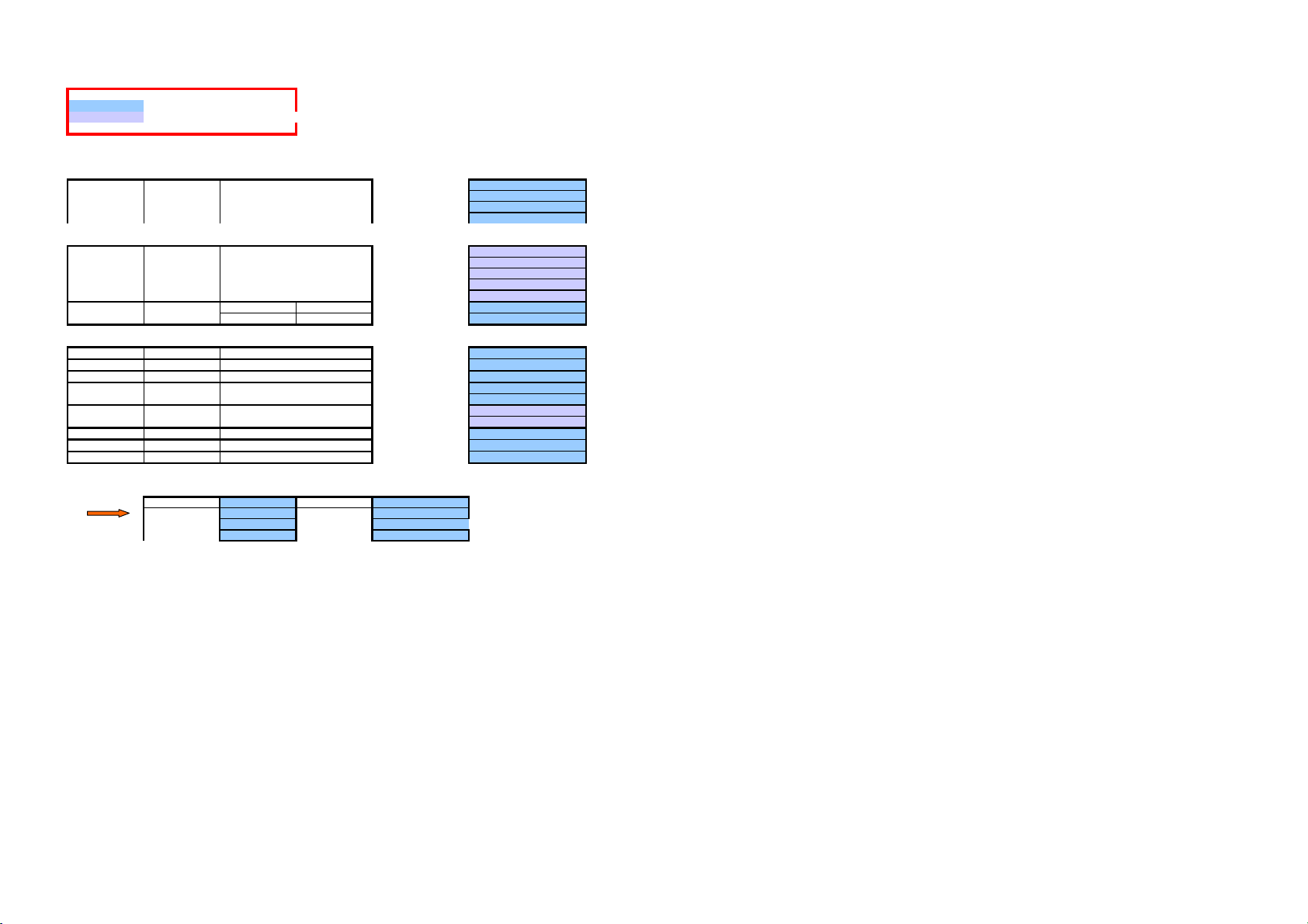
Page 44

<- back
0xc0 Update owner information
0xc1 Update date &time
0xc5 Update password
0xc7 Update SDAP
0xc8 Update PJTALK
0xca Update SNMP
Length 1
Data [0]
fixed to 0
0xc6 Update network
Length 1
Data [0]
bit0 DHCP
bit1 IP
bit2 SUBNET
bit3 GATEWAY
bit4 DNS
bit5 SPEED
Update (sets the changed one to 1)
0xc9 Update mail report
Length 1
Data [0]
bit0 MAINTE RESET
bit1 TEST MAIL
0xc2 Reboot command
Length 6
Data
"reboot"
0xc3 Flash Write command
Length 6
Data
"flashw"
Page 45

<- back
g
Length 2
Data
[0][1]
(decimal) reason result string
0 No send request
1 Sending
100 success OK
200
201 the receiver's address, to_addr, is NULL or invalid. Internal Error 201
202 invalid messa
e body, for example, NULL or invalid buffer pInternal Error 202
203 invalid message size,for example,buflen<=0. Internal Error 203
204 No server Could not find SMTP server.
205 no mailbox Could not find user's mailbox.
206 TCP layer Error in transmiting message. Internal Error 206
207 email message cancelled (with MCDlete()) Internal Error 207
208 mailbox syntax error SMTP transaction error.
209 mailbox busy SMTP mailbox busy.
213 other errors Unexpected error.
300 POP3 login failed.
310 POP3 logout failed.
320
400
401 Could not find SMTP server Could not find SMTP server.
410
411 Cound not find POP server Could not find POP server.
402 DNS not specified.
412 DNS not specified.
500 Internal Error 500
501
502
Page 46

<- back
_
_typ
_typ
_typ
Length 125
Data
pack(1)
typedef struct {
u_short error Mail send result code
u_char mail_type Mail type
u_char date[3] Mail send date yymmdd
u_char time[2] Mail send time hhmm
} MAIL_LOG_RECORD
typedef struct {
LOG_RECORrecord[15]; Save 15 logs
MAIL
u_char write Log number to be written next
int total Total number of errors
} MAILREPORT_LOG
MAILREPORT_LOG mail_log
The logs are displayed from the newer ones by referring to "mail_log.write" and "mail_log.total".
Map ->
[0] 15 14 13 12 11 10 9 8
[1] 76543210
[2] 76543210mail
[3] 76543210 yy
data[0]
[4] 76543210 mm
[5] 76543210 dd
[6] 76543210 hh
[7] 76543210 mm
[8] 15 14 13 12 11 10 9 8
[9] 76543210
[10] 76543210mail
[11] 76543210 yy
data[1]
[12] 76543210 mm
[13] 76543210 dd
[14] 76543210 hh
[15] 76543210 mm
……
[112] 15 14 13 12 11 10 9 8
[113] 76543210
[114] 76543210mail
[115] 76543210 yy
data[14]
[116] 76543210 mm
[117] 76543210 dd
[118] 76543210 hh
[119] 76543210 mm
write [120] 76543210
[121] 31 30 29 28 27 26 25 24
[122] 23 22 21 20 19 18 17 16
total
[123] 15 14 13 12 11 10 9 8
[124] 76543210
error
e
date
time
error
e
date
time
error
e
date
time
Page 47

<- back
_
Length 164
Data
pack(4)
typedef struct {
u_char internal; NS7520 detection error
u_char pj[5]; Error received from H8
} PJ_ERROR;
typedef struct {
PJ_ERROR error; Error flag
u_long set_timer; Set timer when an error occurs
u_char date[3]; Date yy/mm/dd
} PJERROR_LOG_RECORD
typedef struct {
PJERROR
LOG_RECOrecord[10]; Save 10 logs
u_char windex; Log number to be written next
} PJERROR_LOG;
PJERROR_LOG error_log
The logs are displayed from the newer ones by referring to "error_log.windex".
If all of the error contents are 0, that record is regarded to be empty.
Map ->
Page 48

[0] 76543210error.internal
[6]
[7]
[15]
[22]
[23]
[31]
[
]
[
]
[
]
[
]
[
]
[
]
[1] 39 38 37 36 35 34 33 32
[2] 31 30 29 28 27 26 25 24
[3] 23 22 21 20 19 18 17 16
[4] 15 14 13 12 11 10 9 8
[5] 76543210
padding
record[0]
[8] 31 30 29 28 27 26 25 24
padding
[9] 23 22 21 20 19 18 17 16
[10] 15 14 13 12 11 10 9 8
[11] 76543210
[12] 76543210 yy
[13] 76543210 mm
[14] 76543210 dd
padding
[16] 76543210error.internal
[17] 39 38 37 36 35 34 33 32
[18] 31 30 29 28 27 26 25 24
[19] 23 22 21 20 19 18 17 16
[20] 15 14 13 12 11 10 9 8
[21] 76543210
padding
record[1]
[24] 31 30 29 28 27 26 25 24
padding
[25] 23 22 21 20 19 18 17 16
[26] 15 14 13 12 11 10 9 8
[27] 76543210
[28] 76543210 yy
[29] 76543210 mm
[30] 76543210 dd
padding
……
[144] 76543210error.internal
[145] 39 38 37 36 35 34 33 32
[146] 31 30 29 28 27 26 25 24
[147] 23 22 21 20 19 18 17 16
[148] 15 14 13 12 11 10 9 8
[149] 76543210
padding
padding
record[9]
150
151
[152] 31 30 29 28 27 26 25 24
[153] 23 22 21 20 19 18 17 16
[154] 15 14 13 12 11 10 9 8
[155] 76543210
[156] 76543210 yy
[157] 76543210 mm
[158] 76543210 dd
159
padding
windex [160] 76543210
161
162
163
padding
padding
padding
error.pj
set_timer
date
error.pj
set_timer
date
error.pj
set_timer
date
Page 49

<- back
p
e
_
Length 96
Data
pack(4)
typedef struct {
u_short
rev_lamp_timer[2Lamp illumination time right before lamp res
u_long set_timer Set timer at lamp reset
u_char date[3] Date yy/mm/dd
} PJ_TRACE_LAMP_RESET;
PJ
TRACE_LAMP_RElamp_reset[8]; Save eight logs
Dates are displayed in the order from new to old.
If "prev_lamp_timer" is 0, that record is regarded to have no log.
Map ->
Page 50

[11]
[23]
[95]
]
]
]
]
lamp_reset[0]
]
]
lamp_reset[1]
……
lamp_reset[7]
[0] 15 14 13 12 11 10 9 8
[1]76543210
[2] 15 14 13 12 11 10 9 8
[3]76543210
rev_lamp_timer[0
rev_lamp_timer[1
[4] 31 30 29 28 27 26 25 24
[5] 23 22 21 20 19 18 17 16
[6] 15 14 13 12 11 10 9 8
Set Timer
[7]76543210
[8]76543210 yy
[9]76543210 mm
date
[10] 76543210 dd
padding
[12] 15 14 13 12 11 10 9 8
[13] 76543210
[14] 15 14 13 12 11 10 9 8
[15] 76543210
rev_lamp_timer[0
rev_lamp_timer[1
[16] 31 30 29 28 27 26 25 24
[17] 23 22 21 20 19 18 17 16
[18] 15 14 13 12 11 10 9 8
Set Timer
[19] 76543210
[20] 76543210 yy
[21] 76543210 mm
date
[22] 76543210 dd
padding
[84] 15 14 13 12 11 10 9 8
[85] 76543210
[86] 15 14 13 12 11 10 9 8
[87] 76543210
rev_lamp_timer[0
rev_lamp_timer[1
[88] 31 30 29 28 27 26 25 24
[89] 23 22 21 20 19 18 17 16
[90] 15 14 13 12 11 10 9 8
Set Timer
[91] 76543210
[92] 76543210 yy
[93] 76543210 mm
date
[94] 76543210 dd
padding
Page 51

<- back
IP ROM Version
Length 4
Data
[0] [1] [2] [3]
MSB LSB
"%02d.%02d", ver/100, ver%100
Page 52

<- back
Number Of Host
Length 1
Data
[0]
0 Min
…
4 Max
Page 53

<- back
Port Number
Length 2
Data
[0] [1]
high low
0 Min
…
65535 Max
Page 54

<- back
Interval
Length 1
Data
[0]
10 Min
…
65535 Max Unit: second
Page 55

<- back
Maintenance Notification Time
Length 4
Data
[0] [1] [2] [3]
MSB LSB
2 Min
…
99999 Max Unit: hour
Page 56

<- back
Lamp Notification Time
Length 2
Data
[0] [1]
high low
2 Min
…
9999 Max Unit: hour
Page 57

<- back
SNMP Access right
Length 1
Data
[0]
0 Read Only
1 Read/Write
2 Other
Page 58

<- back
R
Mail Report Condition
Length 1
Data
b7 b6 b5 b4 b3 b2 b1 b0
--- REGULARMAINTENANCEERROR--- REGULARMAINTENANCEERRO
To1 To2
Cc1 Cc2
Page 59

<- back
Mail Format
Length 1
Data
[0]
0 Standard
1 Simple
Page 60

<- back
SMTP Authentication Type
Length 1
Data
[0]
0 POP before SMTP
1 SMTP Auth
Page 61

<- back
A
t
n n-byte long, fixed character string. A terminal NULL is not included in the n by
Page 62

<- back
Character string of up to n bytes. The terminal NULL need not be included in the n bytes.
If it is shorter than that, terminate the string with a NULL.
Page 63

<- back
Ethernet MAC Address
Length 6
Data
[0] [1] [2] [3] [4] [5]
0x08 0x00 0x46
Fixed Variable
Page 64

<- back
Ethernet Speed
Length 1
Data
[0]
0 100 Mbps/Full Duplex
1 100 Mbps/Half Duplex
2 10 Mbps/Full Duplex
3 10 Mbps/Half Duplex
4 Auto Detect
Page 65

<- back
Length 1
Data
[0]
0 OFF Disabled Prohibited
1 ON Enabled Allowed
Page 66

<- back
IP Address Format
Length 4
Data
[0] [1] [2] [3]
aaabbbccc ddd
Length 16
Data
[0] [1] [2] [3] [4] [5] [6] [7] [8] [9] [10] [11] [12] [13] [14] [15]
aaabbbccc dddaaabbbccc dddaaabbbccc dddaaabbbccc ddd
First Second Third Fourth
IP Address : aaa.bbb.ccc.ddd
Page 67

<- back
Lens Name
Length 1
Data
[0]
0 VPLL-ZP310
1 VPLL-ZP400
2 VPLL-ZP550
Page 68

<- back
n
Time Zone
Length 1
Data
[0]
0 (GMT-12:00) Eniwetok, Kwajalein
1 (GMT-11:00) Midway Island, Samoa
2 (GMT-10:00) Hawaii
3 (GMT-09:00) Alaska
4 (GMT-08:00) Pacific Time (US & Canada); Tijuana
5 (GMT-07:00) Arizona
6 (GMT-07:00) Mountain Time (US & Canada)
7 (GMT-06:00) Saskatchewan
8 (GMT-06:00) Mexico City
9 (GMT-06:00) Central America
10 (GMT-06:00) Central Time (US & Canada)
11 (GMT-05:00) Indiana (East)
12 (GMT-05:00) Bogota, Lima, Quito
13 (GMT-05:00) Eastern Time (US & Canada)
14 (GMT-04:00) Caracas, La Paz
15 (GMT-04:00) Santiago
16 (GMT-04:00) Atlantic Time (Canada)
17 (GMT-03:30) Newfoundland
18 (GMT-03:00) Greenland
19 (GMT-03:00) Buenos Aires, Georgetown
20 (GMT-03:00) Brasilia
21 (GMT-02:00) Mid-Atlantic
22 (GMT-01:00) Azores
23 (GMT-01:00) Cape Verde Is.
24 (GMT) Casablanca, Monrovia
25 (GMT) Greenwich Mean Time : Dublin, Edinburgh, Lisbon, Londo
26 (GMT+01:00) Amsterdam, Berlin, Bern, Rome, Stockholm, Vienna
27 (GMT+01:00) Sarajevo, Skopje, Sofija, Vilnius, Warsaw, Zagreb
28 (GMT+01:00) Brussels, Copenhagen, Madrid, Paris
29 (GMT+01:00) Belgrade, Bratislava, Budapest, Ljubljana, Prague
30 (GMT+01:00) West Central Africa
31 (GMT+02:00) Athens, Istanbul, Minsk
32 (GMT+02:00) Jerusalem
33 (GMT+02:00) Cairo
34 (GMT+02:00) Harare, Pretoria
35 (GMT+02:00) Bucharest
36 (GMT+02:00) Helsinki, Riga, Tallinn
37 (GMT+03:00) Kuwait, Riyadh
38 (GMT+03:00) Nairobi
39 (GMT+03:00) Baghdad
40 (GMT+03:00) Moscow, St. Petersburg, Volgograd
41 (GMT+03:30) Tehran
42 (GMT+04:00) Abu Dhabi, Muscat
43 (GMT+04:00) Baku, Tbilisi, Yerevan
44 (GMT+04:30) Kabul
45 (GMT+05:00) Islamabad, Karachi, Tashkent
46 (GMT+05:00) Ekaterinburg
47 (GMT+05:30) Calcutta, Chennai, Mumbai, New Delhi
48 (GMT+05:45) Kathmandu
49 (GMT+06:00) Astana, Dhaka
50 (GMT+06:00) Almaty, Novosibirsk
51 (GMT+06:00) Sri Jayawardenepura
52 (GMT+06:30) Rangoon
53 (GMT+07:00) Krasnoyarsk
54 (GMT+07:00) Bangkok, Hanoi, Jakarta
55 (GMT+08:00) Irkutsk, Ulaan Bataar
56 (GMT+08:00) Kuala Lumpur, Singapore
57 (GMT+08:00) Perth
58 (GMT+08:00) Taipei
59 (GMT+08:00) Beijing, Chongqing, Hong Kong, Urumqi
60 (GMT+09:00) Seoul
61 (GMT+09:00) Yakutsk
62 (GMT+09:00) Osaka, Sapporo, Tokyo
63 (GMT+09:30) Adelaide
64 (GMT+09:30) Darwin
65 (GMT+10:00) Vladivostok
66 (GMT+10:00) Canberra, Melbourne, Sydney
67 (GMT+10:00) Guam, Port Moresby
68 (GMT+10:00) Brisbane
69 (GMT+10:00) Hobart
70 (GMT+11:00) Magadan, Solomon Is., New Caledonia
71 (GMT+12:00) Auckland, Wellington
72 (GMT+12:00) Fiji, Kamchatka, Marshall Is.
Page 69

<- back
Date & Time
Length 3
Data
[0] [1] [2]
yy mmdd
yy year 3-99(d)
mm month 1-12(d)
dd day 1-31(d)
Length 2
Data
[0] [1]
hh mm
hh hour 0-23(d)
mm minute 0-59(d)
Invalid when a number larger than 30 is specified for the day in the months of 4, 6, 9 or 11.
Invalid when a number larger than 29 is specified for the day of February (2) of the year that is divisible by 4.
Invalid when a number larger than 28 is specified for the day of February (2) of the year that is not divisible by 4.
 Loading...