

Page 1

HD CAMCORDER SRW-9000
HD CAMCORDER
SRW-9000
HD-SDI EXPANSION BOARD
HKSR-9001
PICTURE CACHE BOARD
HKSR-9002
FILTER SERVO UNIT
HKSR-9004
SRW-9000
(SY)
4-160-062-05 (1)
Sony Corporation
Printed on recycled paper.
Printed in Japan
2012.01 32
© 2009
OPERATION MANUAL [English]
1st Edition (Revised 4)
Page 2

Before operating the unit, please read this
manual thoroughly and retain it for future
reference.
WARNING
To reduce the risk of fire or
electric shock, do not expose this
apparatus to rain or moisture.
To avoid electrical shock, do not
open the cabinet. Refer servicing
to qualified personnel only.
Excessive sound pressure from earphones
and headphones can cause hearing loss.
In order to use this product safely, avoid
prolonged listening at excessive sound
pressure levels.
For the customers in the U.S.A.
This equipment has been tested and found to
comply with the limits for a Class B digital
device, pursuant to Part 15 of the FCC Rules.
These limits are designed to provide
reasonable protection against harmful
interference in a residential installation. This
equipment generates, uses, and can radiate
radio frequency energy and, if not installed
and used in accordance with the instructions,
may cause harmful interference to radio
communications. However, there is no
guarantee that interference will not occur in a
particular installation. If this equipment does
cause harmful interference to radio or
television reception, which can be
determined by turning the equipment off and
on, the user is encouraged to try to correct
the interference by one or more of the
following measures:
— Reorient or relocate the receiving
antenna.
— Increase the separation between the
equipment and receiver.
— Connect the equipment into an outlet on a
circuit different from that to which the
receiver is connected.
— Consult the dealer or an experienced
radio/TV technician for help.
You are cautioned that any changes or
modifications not expressly approved in this
manual could void your authority to operate
this equipment.
All interface cables used to connect
peripherals must be shielded in order to
comply with the limits for a digital device
pursuant to Subpart B of Part 15 of FCC
Rules.
This device complies with Part 15 of the FCC
Rules. Operation is subject to the following
two conditions: (1) this device may not cause
harmful interference, and (2) this device must
accept any interference received, including
interference that may cause undesired
operation.
For the customers in Canada
This Class B digital apparatus complies with
Canadian ICES-003.
For the customers in Europe
This product with the CE marking complies
with the EMC Directive issued by the
Commission of the European Community.
Compliance with this directive implies
conformity to the following European
standards:
• EN55103-1: Electromagnetic Interference
(Emission)
• EN55103-2: Electromagnetic Susceptibility
(Immunity)
This product is intended for use in the
following Electromagnetic Environments: E1
(residential), E2 (commercial and light
industrial), E3 (urban outdoors), E4
(controlled EMC environment, ex. TV studio).
Hereby, Sony Corporation, declares that this
SRW-9000/HD Camcorder is in compliance
with the essential requirements and other
relevant provisions of the Directive 1999/5/
EC.
For details, please access the following URL:
http://www.compliance.sony.de/
Con la presente Sony Corporation dichiara
che questo SRW-9000/HD Camcorder è
conforme ai requisiti essenziali ed alle altre
disposizioni pertinenti stabilite dalla direttiva
1999/5/CE.
Per ulteriori dettagli, si prega di consultare il
seguente URL: http://
www.compliance.sony.de/
2
Page 3

Por medio de la presente Sony Corporation
declara que el SRW-9000/HD Camcorder
cumple con los requisitos esenciales y
cualesquiera otras disposiciones aplicables
o exigibles de la Directiva 1999/5/CE.
Para mayor información, por favor consulte
el siguiente URL: http://
www.compliance.sony.de/
Hierbij verklaart Sony Corporation dat het
toestel SRW-9000/HD Camcorder in
overeenstemming is met de essentiële eisen
en de andere relevante bepalingen van
richtlijn 1999/5/EG.
Nadere informatie kunt u vinden op: http://
www.compliance.sony.de/
Härmed intygar Sony Corporation att denna
SRW-9000/HD Camcorder står I
överensstämmelse med de väsentliga
egenskapskrav och övriga relevanta
bestämmelser som framgår av direktiv 1999/
5/EG.
För ytterligare information gå in på följande
hemsida: http://www.compliance.sony.de/
Sony Corporation declara que este SRW9000/HD Camcorder está conforme com os
requisitos essenciais e outras disposições da
Directiva 1999/5/CE.
Para mais informacoes, por favor consulte a
seguinte URL: http://
www.compliance.sony.de/
Sony Corporation tímto prohlašuje, že tento
SRW-9000/HD Camcorder je ve shode se
základními požadavky a dalšími príslušnými
ustanoveními smernice 1999/5/ES.
Podrobnosti lze získat na následující URL:
http://www.compliance.sony.de/
Sony Corporation kinnitab käesolevaga
seadme SRW-9000/HD Camcorder
vastavust 1999/5/EÜ direktiivi põhinõuetele
ja nimetatud direktiivist tulenevatele teistele
asjakohastele sätetele.
Üksikasjalikum info: http://
www.compliance.sony.de/
Undertegnede Sony Corporation erklærer
herved, at følgende udstyr SRW-9000/HD
Camcorder overholder de væsentlige krav og
øvrige relevante krav i direktiv 1999/5/EF.
For yderligere information gå ind på følgende
hjemmeside: http://
www.compliance.sony.de/
Sony Corporation vakuuttaa täten että SRW9000/HD Camcorder tyyppinen laite on
direktiivin 1999/5/EY oleellisten vaatimusten
ja sitä koskevien direktiivin muiden ehtojen
mukainen.
Halutessasi lisätietoja, käy osoitteessa: http:/
/www.compliance.sony.de/
Sony Corporation erklærer herved at utstyret
SRW-9000/HD Camcorder er i samsvar med
de grunnleggende krav og øvrige relevante
krav i direktiv 1999/5/EF.
For flere detaljer, vennligst se: http://
www.compliance.sony.de/
3
Page 4

For the customers in Taiwan only
AVERTISSEMENT
Afin de réduire les risques
d’incendie ou d’électrocution, ne
pas exposer cet appareil à la
pluie ou à l’humidité.
Afin d’écarter tout risque
d’électrocution, garder le coffret
fermé. Ne confier l’entretien de
l’appareil qu’à un personnel
qualifié.
Une pression acoustique excessive en
provenance des écouteurs ou du casque
peut provoquer une baisse de l’acuité
auditive.
Pour utiliser ce produit en toute sécurité,
évitez l’écoute prolongée à des pressions
sonores excessives.
The manufacturer of this product is Sony
Corporation, 1-7-1 Konan, Minato-ku, Tokyo,
108-0075 Japan.
The Authorized Representative for EMC and
product safety is Sony Deutschland GmbH,
Hedelfinger Strasse 61, 70327 Stuttgart,
Germany. For any service or guarantee
matters please refer to the addresses given
in separate service or guarantee documents.
For the State of California, USA only
Perchlorate Material - special handling may
apply, See
www.dtsc.ca.gov/hazardouswaste/
perchlorate
Perchlorate Material : Lithium battery
contains perchlorate.
4
Pour les clients au Canada
Cet appareil numérique de la classe B est
conforme à la norme NMB-003 du Canada.
Pour les clients en Europe
Ce produit portant la marque CE est
conforme à la Directive sur la compatibilité
électromagnétique (EMC) émise par la
Commission de la Communauté
européenne.
La conformité à cette directive implique la
conformité aux normes européennes
suivantes:
• EN55103-1 : Interférences
électromagnétiques (émission)
• EN55103-2 : Sensibilité électromagnétique
(immunité)
Ce produit est prévu pour être utilisé dans les
environnements électromagnétiques
suivants : E1 (résidentiel), E2 (commercial et
industrie légère), E3 (urbain extérieur) et E4
Page 5

(environnement EMC contrôlé, ex. studio de
télévision).
Par la présente Sony Corporation déclare
que l’appareil SRW-9000/HD Camcorder est
conforme aux exigences essentielles et aux
autres dispositions pertinentes de la directive
1999/5/CE.
Pour toute information complémentaire,
veuillez consulter l’URL suivante: http://
www.compliance.sony.de/
Le fabricant de ce produit est Sony
Corporation, 1-7-1 Konan, Minato-ku, Tokyo,
108-0075 Japon.
Le représentant autorisé pour EMC et la
sécurité des produits est Sony Deutschland
GmbH, Hedelfinger Strasse 61, 70327
Stuttgart, Allemagne. Pour toute question
concernant le service ou la garantie, veuillez
consulter les adresses indiquées dans les
documents de service ou de garantie
séparés.
WARNUNG
Um die Gefahr von Bränden oder
elektrischen Schlägen zu
verringern, darf dieses Gerät
nicht Regen oder Feuchtigkeit
ausgesetzt werden.
• EN55103-1: Elektromagnetische
Verträglichkeit (Störaussendung)
• EN55103-2: Elektromagnetische
Verträglichkeit (Störfestigkeit)
Für die folgenden elektromagnetischen
Umgebungen: E1 (Wohnbereich), E2
(kommerzieller und in beschränktem Maße
industrieller Bereich), E3 (Stadtbereich im
Freien) und E4 (kontrollierter EMV-Bereich,
z.B. Fernsehstudio).
Hiermit erklärt Sony Corporation, dass sich
das Gerät SRW-9000/HD Camcorder in
Übereinstimmung mit den grundlegenden
Anforderungen und den übrigen
einschlägigen Bestimmungen der Richtlinie
1999/5/EG befindet.
Weitere Informationen erhältlich unter: http://
www.compliance.sony.de/
Der Hersteller dieses Produkts ist Sony
Corporation, 1-7-1 Konan, Minato-ku, Tokyo,
108-0075 Japan.
Der autorisierte Repräsentant für EMV und
Produktsicherheit ist Sony Deutschland
GmbH, Hedelfinger Strasse 61, 70327
Stuttgart, Deutschland. Bei jeglichen
Angelegenheiten in Bezug auf Kundendienst
oder Garantie wenden Sie sich bitte an die in
den separaten Kundendienst- oder
Garantiedokumenten aufgeführten
Anschriften.
Um einen elektrischen Schlag zu
vermeiden, darf das Gehäuse
nicht geöffnet werden.
Überlassen Sie
Wartungsarbeiten stets nur
qualifiziertem Fachpersonal.
Zu hoher Schalldruck von Ohrhörern und
Kopfhörern kann Gehörschäden
verursachen.
Um dieses Produkt sicher zu verwenden,
vermeiden Sie längeres Hören bei sehr
hohen Schalldruckpegeln.
Für Kunden in Europa
Dieses Produkt besitzt die CEKennzeichnung und erfüllt die EMVRichtlinie der EG-Kommission.
Angewandte Normen:
5
Page 6

Table of Contents
Chapter 1 Overview
Features ...................................................................................................... 11
Example System Configuration................................................................ 13
Locations and Functions of Parts............................................................. 15
Front Panel ...................................................................................... 15
Left Side.......................................................................................... 16
Right Side........................................................................................ 17
Display/Menu Operations Section .................................................. 18
Rear Panel ....................................................................................... 19
Upper Panel..................................................................................... 20
Control Panel................................................................................... 20
Display ............................................................................................ 25
AP-1 Assistant Panel (Optional)..................................................... 27
Chapter 2 Preparations
Connecting a Power Supply...................................................................... 28
Using a Battery Pack....................................................................... 28
Using AC Power ............................................................................. 29
Turning on the Power...................................................................... 29
Checking the Power and Voltage.................................................... 29
Mounting the Lens..................................................................................... 30
Attaching the Viewfinder .......................................................................... 32
Connecting Audio Input............................................................................ 33
Using a Microphone........................................................................ 33
Connecting Line Input Audio Equipment....................................... 33
Connecting an Audio Multiplexer (MUX) to the AUX IN Connector
(When Using the HKSR-9001)................................................. 34
Mounting on a Tripod ............................................................................... 35
Attaching the Control Panel ..................................................................... 36
Attaching the AP-1 Assistant Panel (Optional)....................................... 38
Setting the Built-in Clock.......................................................................... 39
Table of Contents
6
Page 7

Chapter 3 Basic Adjustments and Settings
Selecting the Basic Operation Mode ........................................................ 40
Overview of the Basic Operation Modes........................................ 40
Switching between the Basic Operation Modes.............................. 40
Basic Settings with the Subdisplay........................................................... 41
Basic Operations in the Subdisplay................................................. 41
Shutter Settings ............................................................................... 42
Using the Ramp Function................................................................ 45
Selecting the Video Formats........................................................... 46
Displaying the Filter Status............................................................. 47
Selecting Gain, Color Temperature, and White Balance Values .... 47
Selecting a Lens File....................................................................... 49
Checking the Operating Status of the VTR Module....................... 49
Checking Timecode and the Remaining Tape Time....................... 49
Setting the Timecode Generator Value to XX:00:00:00................. 50
Checking the Power Voltage and Selecting the Fan Mode............. 50
Character Data On and Off ............................................................. 51
Assigning Functions to Assignable Buttons/Switch....................... 51
Adjusting the Brightness of the Subdisplay.................................... 52
Selecting Gamma Tables................................................................. 52
Selecting Pages to Display in the Subdisplay ................................. 53
Adjusting the Black Balance..................................................................... 54
Adjusting the White Balance (in Custom Mode) .................................... 55
Setting the Camera Outputs ..................................................................... 56
Selecting Video Output Signals for the Connectors ....................... 56
Setting the Monitor Picture............................................................. 57
Outputting Color Bars..................................................................... 59
Outputting Rec Trigger Signals ...................................................... 60
Viewing Settings and Indications in the Viewfinder .............................. 61
Viewing the Basic Status ................................................................ 61
Viewing the ABNORMAL <!> Display......................................... 63
Viewing the FUNCTION (Format/Switch Function)/SYSTEM
(System Settings/FILTER ASSIGN) Display........................... 64
Specifying and Displaying Markers................................................ 65
Making Viewfinder Detail Adjustments......................................... 66
Displaying Zebra Patterns............................................................... 66
Specifying and Displaying Cursors................................................. 67
Checking the Power Supply Voltage .............................................. 68
Detailed Function Settings ........................................................................ 69
Setting the Gain.......................................................................................... 70
Detailed Shutter Settings........................................................................... 71
Restoring Factory Default Settings .......................................................... 72
Table of Contents
7
Page 8

Selecting the Gamma................................................................................. 73
Using the Standard Gamma ............................................................ 73
Using HyperGamma........................................................................ 73
Using S-LOG .................................................................................. 74
Using User Gamma......................................................................... 75
Inverting the Camera Picture................................................................... 76
Display Settings.......................................................................................... 76
Detailed Video Format Settings................................................................ 77
Setting the Video Format in the Camera Menu .............................. 77
Setting the Video Format in the VTR Menu................................... 78
Relation between Playback and Recording Signals and Video Monitor
Output Signals........................................................................... 79
Power Saving Mode ................................................................................... 81
Chapter 4 Recording/Playback
About Cassettes.......................................................................................... 82
Loading and Unloading Cassettes................................................... 82
Preventing Accidental Erasure........................................................ 83
Recording.................................................................................................... 83
Setting System Signal Format......................................................... 83
Making Audio Signal Settings ........................................................ 85
Setting Recording Audio Levels..................................................... 86
Making Timecode and User Bits Settings....................................... 87
Shooting .......................................................................................... 90
Continuous Recording..................................................................... 90
Playback – Checking the Recording ........................................................ 92
Preparing for Playback.................................................................... 92
Checking the Last Three Seconds of the Recording –Recording
Review ...................................................................................... 93
Checking the Recording on a Color Video Monitor –Playback in
Color ......................................................................................... 93
Checking the Camera Picture on the Viewfinder and/or Color Video
Monitor ..................................................................................... 94
Chapter 5 Memory Recording (With HKSR-9002 Installed)
Timer Rec ................................................................................................... 95
Manual Timer Rec........................................................................... 95
Auto Timer Rec............................................................................... 96
Cache Rec ................................................................................................... 97
Table of Contents
8
Page 9

Chapter 6 SR Motion (With HKSR-9002 Installed)
Overview..................................................................................................... 99
Overview of SR Motion Recording/Playback................................. 99
Operation Flow.............................................................................. 101
Target Frame Frequencies and Signal Formats............................. 101
Select FPS Function................................................................................. 106
Relation Between the Number of Frames Shot and the Number of
Playback Frames (Outline of Select FPS)............................... 106
Using the Select FPS Function...................................................... 107
Using the Ramp Function.............................................................. 110
Interval Frame Function......................................................................... 113
Relation Between the Number of Frames Shot and the Frame interval
(Outline of Interval Frame)..................................................... 114
Using the Interval Frame Function ............................................... 115
Using the Ramp Function.............................................................. 117
Chapter 7 Menu Configuration and Detailed Settings
Camera Menu Configuration ................................................................. 121
Basic Camera Menu Operations ............................................................ 123
Displaying Setting Pages............................................................... 124
Setting Menu Items ....................................................................... 125
Camera Menu List................................................................................... 127
OPERATION Menu...................................................................... 127
PAINT Menu................................................................................. 141
MAINTENANCE Menu............................................................... 150
FILE Menu.................................................................................... 161
DIAGNOSIS Menu....................................................................... 166
Editing the USER Menu.......................................................................... 167
Creating New Pages...................................................................... 167
Returning the USER Menu to the Factory Defaults...................... 170
VTR Menu Operations............................................................................ 170
Displaying VTR Menus ................................................................ 170
Changing Menu Settings............................................................... 170
VTR Menu List ........................................................................................ 172
TC (Timecode) Setup Menu.......................................................... 172
VIDEO Setup Menu...................................................................... 174
AUDIO Setup Menu ..................................................................... 175
SYSTEM Setup Menu................................................................... 177
Table of Contents
9
Page 10

Chapter 8 Storage and Retrieval of User Setting Data
File Configuration.................................................................................... 185
List of Items Stored in Files .................................................................... 187
File Operations......................................................................................... 189
Using a “Memory Stick”............................................................... 189
Storage and Retrieval of the Operator File ................................... 190
Registration and Retrieval of Lens Files....................................... 190
Storage and Retrieval of the Scene Files....................................... 191
Storage and Retrieval of Reference Files...................................... 192
Reading User Gamma Curves....................................................... 193
Reading User MLUT Files............................................................ 193
Storing OHB Files......................................................................... 193
Resetting to the Factory Defaults.................................................. 194
Appendixes
Using the RM-B750.................................................................................. 196
Connection .................................................................................... 196
Operating the Camera Menu ......................................................... 196
Monitoring the Camera Image ...................................................... 197
Warning System....................................................................................... 198
Warning/Error Messages........................................................................ 200
Warning and Error Messages Related to the Camera Module...... 200
Error Messages Related to the VTR Module................................ 201
Warning Messages Related to the VTR Module........................... 202
Precautions............................................................................................... 205
About a “Memory Stick” ........................................................................ 206
Maintenance and Inspections ................................................................. 207
Head Cleaning............................................................................... 207
Condensation................................................................................. 207
Note About the Battery Terminal.................................................. 207
About Recording/Playback Formats...................................................... 208
What Are Dual Link and 3G? ................................................................ 210
MPEG-4 VISUAL PATENT PORTFOLIO LICENSE ....................... 212
Specifications............................................................................................ 212
Lip Sync Compensation .......................................................................... 215
Index.......................................................................................................... 216
Table of Contents
10
Page 11

Chapter1 Overview
Features
The SRW-9000 is an HDCAM SR format
integrated camcorder.
It combines the high quality and high
performance of HDCAM SR recording with the
superior mobility of a compact camcorder. Its
features and performance make it ideal for
shooting in situations ranging from movie and
commercial production to studio programming,
television dramas, and documentaries.
Superior Picture Quality and High
Performance
High-performance digital recording in HDCAM
SR format
The SRW-9000 (called “this unit” below),
records and plays back component video signals
that comply with the MPEG-4 Studio Profile, an
international video signal compression standard.
It supports the standard 440 Mbps recording
format of the SRW series (HDCAM SR VTRs),
and also a double-speed 880 Mbps recording
1)
It records up to 12 channels of
format.
uncompressed audio signals (24 bits, sampling
frequency 48 kHz).
1) Double-speed recording
Double-speed recording is realized by doubling the
standard drum rotation and tape transport speeds,
allowing twice as much data to be recorded per unit of
time.
This enables recording of high-quality formats such as
1080/50P and 59.94P, and recording in RGB 4:4:4 HQ
mode.
3CCD imaging system with 2/3-inch progressive
CCDs and 14-bit A/D converter
The unit delivers high image quality through a
3CCD imaging system with 2/3-inch progressive
CCDs and a 14-bit A/D converter. The maximum
dynamic range is 800%.
Chapter 1 Overview
Multi frame rate support
The unit supports a variety of 1080 formats for
the production of high-end content such as
movies, commercials, and broadcast
programming.
• 1080 × 1920 (progressive) formats:
23.98PsF/24PsF/25PsF/29.97PsF/50P/59.94P
• 1080 × 1920 (interlaced) formats: 50i/59.94i
RGB 4:4:4 shooting and recording
Because of its high compatibility with computer
graphics and digital compositing systems, the
RGB 4:4:4 format opens up a wide range of
creative possibilities for applications such as
movie-making and commercial production. The
unit offers the same S-LOG gamma as with the
F35/F23 Digital Cinematography Camera, thus
ensuring wide dynamic range shooting.
User Gamma function
This unit inherits the User Gamma function of the
HDW-F900R HD Camcorder. This allows you to
load gamma curves created with the
CvpFileEditor.
The User Gamma function allows you to capture
a look that expresses your creative intentions.
Design and Shape
Compact body and low power consumption
This unit is about two times lighter than previous
HDCAM SR recording systems, and consumes
only about half as much power. Its compact size
and light weight enable capture by small camera
crews. Like prev ious HDCAM camcorders, it can
be powered by Sony BP-GL95 lithium ion battery
packs.
High compatibility with film camera accessories
Using the supplied riser plate, you can connect
industry standard ARRIFLEX movie camera
accessories such as bridge plates, matte boxes,
and follow focus units.
Instead of the riser plate, you can also attach the
supplied V-shoe plate. This allows you to use the
optional VCT-14 Tripod Attachment to mount
the unit on a tripod.
Features
11
Page 12

Assignable buttons/switch
The unit is equipped with 10 assignable buttons/
Chapter 1 Overview
switch on the side panel. For easier operation
during shooting, you can assign frequently used
functions to these switches. You can also assign
basic VTR control functions such as STOP,
PLAY, and REW, which allows you to control
tape transport without using the control panel.
Rich Selection of Functions
Two operation modes: Cine and Custom
This unit offers two operation modes: Cine mode,
for film-like shooting, with adjustments normally
being made in post production, and Custom
mode, for users who wish to obtain a specific look
by adjusting parameters on the set.
Monitor output functions
The unit provides a wide range of monitor output
functions, including mixing of characters and
markers into monitor output, mixing of camera
and playback video, and separate gammas for
monitor and main line.
Down converter
A down converter is provided as a standard
feature, allowing you to monitor camera and V TR
playback video as SD composite on an SD
monitor.
1.5G Dual link output
Installation of the optional HKSR-9001 in this
unit enables output of 1.5G Dual Link signals
(RGB 4:4:4 or 4:2:2 1080/50P).
3G HDSDI output
Installation of the HKSR-9001 enables output of
3G Single Link signals, equivalent to 1.5G Dual
Link signals, over a single BNC cable.
SR Motion™
When the optional HKSR-9002 Picture Cache
Board is installed, SR Motion is available on this
unit. SR Motion allows you to obtain effects
similar to overcranking and undercranking on
film cameras by using HKSR-9002’s built-in
memory while maintaining the high picture
quality of HDCAM-SR (1920 × 1080) format.
SR Motion is available in Select FPS mode.
Select FPS enables variable-speed motion effects
by changing the frame frequency during
recording (Ramp function).
1) SR Motion is a trademark of Sony Corporation.
1)
Timer Rec
When the optional HKSR-9002 Picture Cache
Board is installed, a Timer Rec function is
available on this unit. This allows you to utilize
the memory in the option board to shoot images at
a specified interval. This enables time-lapse
recording and recording over long periods.
Cache Rec
When the optional HKSR-9002 Picture Cache
Board is installed, a Cache Rec function is
available on this unit. This function captures
about 200 frames of the video and audio that the
camera is currently shooting (or about 10 0 frames
in HQ mode) to the memory. Thus, when you
press the recording start button (if the unit is in
standby on mode and SR Motion is not being
used), the recording starts with the data stored
about 200 frames (or about 100 frames in HQ
mode) before.
Shutter control
When adjusting the electronic shutter, you can
display shutter settings as shutter angles (in
degrees) or shutter speeds (in seconds).
Image inversion function
The image inversion function allows you to
cancel out the image inversion that occurs when a
cine-lens converter is used.
Monitoring and recording AUX inputs
Installing the optional HKSR-9001 allows
monitoring and recording the 4:2:2 video signals
input to the AUX IN connector. You can select
the monitoring or recording target between the
camera picture and the AUX inputs by menu
setting.
Removable control panel
The control panel is independent of the unit,
allowing it to be installed in the most convenient
location in your operating environment. It can be
held in the hand and operated like a remote
controller.
AP-1 Assistant Panel (optional)
The optional AP-1 Assistant Panel provides the
same functions as the control panel on the right
side of the unit. It enables convenient control of
basic camera operations such as shutter control
(indication in degrees possible), gain and color
temperature settings (selection of Tungsten and
Daylight possible), timecode and tape remaining
checks, control of character display, and
12
Features
Page 13

assignment of functions to the assignable buttons/
switch.
Per-channel audio level adjustments
You can check peaks and adjust audio playback
and recording levels independently on all 12
audio channels.
Example System Configuration
The figure below shows a camera system
configured around this unit. In this manual,
figures and explanations assume that you are
using the optional HDVF-C30WR HD Electronic
Viewfinder.
For more information about attaching, connecting,
and using additional equipment and accessories, see
Chapter 2 “Preparations” (page 28) as well as the
operation manuals for the connected equipment.
AP-1 Assistant
Control panel
Main unit
Panel (optional)
Chapter 1 Overview
Riser plate
V-shoe plate
Viewfinder
Name Model name
HD Electronic
Viewfinder
Viewfinder-related equipment
Name/purpose Magnification Part No.
Fog-proof filter — 1-547-341-11
Eyepiece (high
magnification)
HDVF-20A/C30WR
–2.8D to
+2.0D
Example System Configuration
A-8262-537-A
13
Page 14

Name/purpose Magnification Part No.
Chapter 1 Overview
Eyepiece (low
magnification)
Eyepiece
(aberration
compensation)
Eyepiece (×3
magnification)
–3.6D to
–0.8D
–3.6D to
+0.4D
–2.4D to
+0.5D
Products for battery operation
Name Model name
Battery Pack BP-GL95
Battery Charger BC-L70/M150
Products for audio input
Name Model name
UHF Synthesized
Tuner Un it
Microphone ECM-678/674
Microphone Holder CAC-12
HDSDI 4-Channel
Analog Audio
Embedder/
Disembedder
WRR-861
HD10AMA (AJA Video)
Products for AC power supply
Name Model name
AC Adaptor AC-DN2B/DN10
Data storage media
“Memory Stick PRO” and “Memory Stick PRO
Duo”
Products for tripod mounting
Name Model name
Tripod Attachment VCT-14
Bridge Plate BP-8 (ARRIFLEX)
Expansion boards
Name Model name
HD-SDI Expansion
Board
Picture Cache Board HKSR-9002
Filter Servo Unit HKSR-9004
HKSR-9001
A-8262-538-A
A-8267-737-A
A-8314-798-A
Remote control devices
Name Model1 name
Remote Control Unit RM-B150/B750
Video and audio output devices
Purpose Name
HD video output
monitoring (HDSDI)
SD video output
monitoring (TEST
OUT)
Audio monitoring
(EARPHONES)
HD video monitor
SD video monitor
Stereo headphones
External video recorders
Name/purpose Model name
HDSDI portable
recorder/player
HDSDI portable
digital video recorder
(Dual Link)
nanoFlash (Convergent
Design)
SRW-1/SRPC-1
Example System Configuration
14
Page 15

Locations and Functions of Parts
Front Panel
a VF (viewfinder) connector (20-pin)
Connect an optional viewfinder.
b Viewfinder shoe
Attach an optional viewfinder. You can adjust the
attachment position up and down.
For details, see “Attaching the Viewfinder” (page
32).
c Filter selector
The selector knobs switch between the unit’s
built-in filters.
Filter selector (outer knob) settings and optical
CC (color conversion) filter selection
Setting knob CC filter selection
A 3200K
B 4300K
C 5600K
D 6300K
E
Filter selector (inner knob) settings and ND filter
selection
Setting knob ND filter selection
1 CLEAR
2
3
4
5CAP
ND 0.3 (
ND 0.6 (
ND 1.2 (
ND 1.8 (
1
/2ND)
1
/4ND)
1
/16ND)
1
/64ND)
You can use the filter label on the right side panel
to check the filters that are selected by the various
knob positions.
When this selector is used, the new setting
appears on the viewfinder screen for about three
seconds.
When the optional HKSR-9 004 is installed, filters
can be electrically switched by the subdisplay or
the switch to which you have assigned the filter
switching function.
For details, see “Adjusting the White Balance (in
Custom Mode)” (page 55).
d LENS connector (12-pin)
If you mount an optional lens with a cable,
connect the cable to this connector. You can
control the functions of the lens through this
connector.
Note
Do not connect a device whose maximum rated current
is 1 A or higher to the LENS connector.
Chapter 1 Overview
e Lens mount cap
Cover the lens mount with this cap when a lens is
not attached. The cover may be removed by
rotating the lens fixing lever upward.
f Lens fixing lever
Push the lever downward to secure the lens in the
lens mount. To remove the lens, pull up on the
lever.
Locations and Functions of Parts
15
Page 16

g Lens mount
Attach the lens. When no lens is mounted, keep
Chapter 1 Overview
the lens mount cap fitted for protection from dust.
For details, see “Mounting the Lens” (page 30).
e Power ON (])/OFF (1) switch and
indicator
Push the switch to the ON side to power the unit
on (the indicator lights). Push it to the OFF side to
power the unit off (the indicator goes out).
Left Side
Shoulder pads
a Cassette insertion slot
Insert cassettes.
For details, see “L oading and Unloading Cassettes”
(page 82).
b CTRL (VTR) (control panel) connector
Connect the cable of the supplied control panel. A
short cable is connected when the unit is shipped
from the factory. You can exchange the short
cable for the supplied extension cable.
For details, see “A ttaching the Control Panel” (pa ge
36).
f EARPHONES jack and LEVEL knob
Use the jack to attach earphones or stereo
headphones equipped with a stereo miniplug, for
use in monitoring audio during recording and
playback. Adjust the audio level with the LEVEL
knob.
A warning sound is heard through the earphones
or headphones when an error occurs.
Note
Some L-type mini plugs cannot be connected. Use a
straight type mini plug.
For details on the warning tone, see “Warning
System” (page 198).
g AUDIO indicator
Lights when the audio level meters (see page 25)
exceed a certain level.
h HD SDI MON1 (HDSDI monitor output
1) connector (BNC type)
Output HDSDI signals for display on a monitor.
You can select/set the output signals in the
Camera menu ( see page 56). The same signals are
output from the HD SDI MON2 connector on the
rear panel.
i EXT I/O (external control) connector
(5-pin)
Use the connector for control via RS-232C.
c Measure hook/focus reference mark (φ)
For actual measurement of the distance from a
subject, you can fix the end of a tape measure to
the hook.
A mark on the side panel (φ) indicates the
reference focus position.
d CTRL (CAM) (assistant panel)
connector
Connect the cable of the optional AP-1 Assistant
Panel.
For details, see “Attaching the AP-1 Assistant Panel
(Optional)” (page 38).
Locations and Functions of Parts
16
Page 17

Right Side
Display/menu operations section (page 18).
a Assignable buttons 5 to 8
You can assign frequently used functions to these
buttons by menu settings. The following
functions are assigned when the unit is shipped
from the factory.
Switches Functions
5STOP
6PLAY
7REW
8F.FWD
For details, see “Assigning Functions to Assignable
Buttons/Switch” (page 51).
b Filter label and assignable buttons N
and C
The filter label show the filters selected by the
knobs of the front panel filter selector. You can
use the Camera menu to assign functions to
assignable buttons N and C. They are set to OFF
(disabled) when the unit is shipped from the
factory.
When the optional HKSR-9004 is installed, the
default values of the assignable buttons N and C
are ND and CC respectively.
For details, see “Assigning Functions to Assignable
Buttons/Switch” (page 51).
c LOCK switch
When slid to the right, locks the operation buttons
on the right-side panel.
If you wish, you can set this switch so that it locks
all buttons except the RUN button. Make this
setting on the <SUBDISPLAY 2> page (see page
121) of the Camera >USER (OPERATION)
menu.
d Assignable 4/AUTO BLK BAL (auto
black balance) switch
Push the switch downward to the AUTO BLK
BAL side to start the auto black balance
adjustment.
You can use the Camera menu to assign a
function to the 4 position (upper position). This
position is set to OFF (disabled) when the unit is
shipped from the factory.
For details, see “Assigning Functions to Assignable
Buttons/Switch” (page 51).
e RUN button and indicator
Starts and stops recording. The indicator lights
during recording, and fla shes when low voltage or
an error is detected.
For more information about the indicator operation,
see “Warning/Error Messages” (page 200).
f “Memory Stick” slot
Allows you to insert a “Memory Stick”.
The access lamp lights in red while the unit is
writing or reading data to/from a “Memory
Stick”. You can use “Memory Stick PRO” or
“Memory Stick PRO Duo” media with this unit.
(“Memory Stick PRO Duo” media can be used
without any adaptor.)
Note
When the access lamp is lit in red, do not insert/remove
the “Memory Stick” or turn off the unit.
See “File Configuration” ( page 185) for information
about data files that can be handled with “Memory
Stick” media.
For details on “Memory Stick” media, see “Using a
“Memory Stick”” (page 189).
g Tripod screw holes
Two screw holes (for 3/8-inch camera screws) are
provided on the bottom-side panel.
Chapter 1 Overview
Locations and Functions of Parts
17
Page 18

h Riser plate/focus reference mark (φ)
This is a plate for attaching movie accessories. It
Chapter 1 Overview
has a mark to show the focus standard position. A
wrench (2.5 mm) for use in attaching and
detaching the viewfinder is stored inside. When
you want to use a tripod with the optional VCT14 Tripod Attachment, exchange the riser plate
for the supplied V-shoe plate.
See “To use the optional VCT-14 Tripod
Attachment” (page 35) for more information about
attaching the V-shoe plate.
i Assignable buttons 1 to 3
You can assign frequently used functions to these
buttons by Camera menu settings. They are set to
OFF (disabled) when the unit is shipped from the
factory.
For details, see “Assigning Functions to Assignable
Buttons/Switch” (page 51).
Display/Menu Operations Section
state. When the Camera menu is not displayed,
you can press this button to display information
about the status of the unit in the subdisplay and
viewfinder.
See “Viewing Settings and Indications in the
Viewfinder” (page 61) for details about the status
information that appears
c Subdisplay
Displays the Camera menu and unit settings. If
you are using the optional AP-1 Assistant Panel,
the same information appears in the subdisplay of
the AP-1.
d PAGE button
In subdisplay screens, switches to the next page
or confirms settings.
e MENU SEL (selection)/ENTER dial
In subdisplay and viewfinder screens, confirms
settings. When the Camera menu is displayed in
the subdisplay and viewfinder, turn the dial to
select menu items.
Note
When you turn the dial, stop it at a position where you
feel a click. If you force the dial to stop at a non-click
position, the operating stability of the dial on the AP-1
side may be affected.
For details, see “Basic Operations in the
Subdisplay” (page 41) or “Basic Camera Menu
Operations” (page 123).
a VF (viewfinder) MENU/DISPLAY
button
Displays and hides menus in the subdisplay and
viewfinder.
b CANCEL/STATUS button
Cancels settings made in the subdisplay and
viewfinder, or returns the display to a previous
Locations and Functions of Parts
18
f SET button
In subdisplay screens, returns to the previous
page. When this button is held down for one
second or longer, the screen enters settings
modification mode.
Page 19

Rear Panel
Setup >OTHERS (MAIN) >TC OUT in the VTR
menu (see page 173).
f TEST OUT connector (BNC type)
Outputs an analog signal selected in the Camera
menu (see page 56).
g DC OUT (DC power output) connector
(4-pin, male)
Supplies 12 V DC power. You can connect the
power cord of the WRR-861 UHF Synthesized
Tuner Unit to this connector.
h DC IN 11-17V (DC power input)
connector (4-pin)
Connect the DC power cord of an AC-DN2B/
DN10 AC Adaptor.
For details, see “Conn ecting a Power Supply” (page
28).
Chapter 1 Overview
a Battery attachment shoe
Attach a battery or AC adaptor.
For details, see “Co nnecting a Power Supply” (page
28).
b Tally indicator and ON/OFF switch
When the switch is set to ON, the tally indicator
lights during recording. The indicator flashes
when low voltage or an error is detected. You can
set the switch to OFF to prevent the indicator
from lighting or flashing.
See “Warning System” (page 198)” for more
information about when the tally indicator flashes.
c GENLOCK IN (external sync signal
input) connector (BNC type)
Used for input of an external genlock signal (HD
tri sync).
d TC IN (timecode input) connector
(BNC type)
Connect to the timecode output connector of a
timecode generator, VTR, or other external
device. Use this connector when you want to lock
the internal timecode generator to external
timecode.
e TC OUT (timecode output) connector
(BNC type)
Connect to the timecode input connector of a
timecode reader, VTR, or other external device.
The output signal depends on the setting of TC
i AUDIO IN (audio input) CH-1/CH-2
connectors (XLR type 3-pin, female
type) and input selection switches
Input audio signals to the CH-1 and CH-2
connectors.
Set the input selection switches according to the
type of the connected signal source.
LINE: When a line-level (+4 dBu) signal source
is connected
MIC: When an external microphone is connected
(no power is supplied.)
MIC +48V ON: When an external microphone is
connected (+48 V power is supplied.)
j HD SDI OUT A/B connectors (BNC
type) and ON/OFF switch (when the
HKSR-9001 is installed)
When the switch is set to ON, HDSDI signals are
output from the A and B connectors. When the
switch is set to OFF, no signals are output.
See “What Are Dual Link and 3G?” (page 210) for
more information about HDSDI signal output.
k REMOTE connector (8-pin)
Connect an external control device, such as the
RM-B150/B750 Remote Control Unit.
l AUX IN (auxiliary input) connector
(BNC type) (when the HKSR-9001 is
installed)
1.5G single link (4:2:2 30PsF or less) HDSDI
signals can be input to this connector and
Locations and Functions of Parts
19
Page 20

recorded. Connect an external device to increase
the number of audio input channels, or to
Chapter 1 Overview
synchronize this unit to the output of an HD
device.
When you use this connector for HDSDI input,
set SYSTEM Setup >FORMAT >INPUT SEL
(see page 179) in the VTR menu to AUX Input.
m HD SDI MON2 (HDSDI monitor
output 2) connector (BNC type)
Use in the same way as the HD SDI MON1
connector on the left-side panel (see page 16).
Upper Panel
Control panel
(page 20)
c Assistant panel attachment screws
Attach the optional AP-1 Assistant Panel or the
CAC-12 Microphone Holder.
For details, see “Attaching the AP-1 Assistant Panel
(Optional)” (page 38) or “Using a Microphone”
(page 33).
d Cable holder attachment screws
Attach the supplied cable holder to hold the cable
of the control panel o r the optional AP-1 Assistant
Panel.
e Accessory attachment screw holes
You can attach accessories to the two screw holes
3
/8" × 1, 1/4" × 1).
(
f EJECT button
Pressing this button opens the lid of the cassette
insertion slot, allowing you to take out the
inserted cassette.
Control Panel
The control panel is used mainly for control of the
VTR module.
With control panel detached
a Lock release button
When removing the control panel, use this button.
For details, see “A ttaching the Control Panel” (pa ge
36).
b Handle
Use to carry the unit.
You can attach an accessory to the seven screw
3
holes (
/8" × 4, 1/4" × 3) on the top of the handle.
You can also attach the CAC-12 Microphone
Holder to the side of the handle.
For details, see “Using a Microphone” (page 33).
Locations and Functions of Parts
20
a VTR menu selection buttons
Select one of the VTR menus or the Camera menu
to be shown on the display.
HOME button: Displays the HOME screen. The
HOME screen displays audio levels,
operating status, warnings, time data, and
other information.
TC button: Displays the TC (timecode) Setup
menu (see page 172). This menu allows you
to switch between LTC and VITC, to switch
between DF and NDF, and to display
timecode on an external monitor.
Page 21

VIDEO button: Displays the VIDEO Setup
menu. The menu allows you to perform
Camera menu operations (see page 123).
AUDIO button: Displays the AUDIO Setup
menu (see page 175). This menu allows you
to make settings related to audio.
SYSTEM button: Displays the SYSTEM Setup
menu (see page 177). This menu allows you
to make settings related to the entire system,
such as recording format, power, and test
signal output.
For details on VTR menus, see “VTR Menu List”
(page 172).
b Display
Displays VTR menus, audio levels, warnings,
operating status, time data, remaining tape time,
and remaining battery power.
For details, see “Display” (page 25).
You can rotate the display to display it vertically
(rotated 90 degrees to the left).
To change the display, press the HOME button
while holding the FUNC and BACK buttons
down.
To return the display to its original orientation,
press the HOME button again while holding the
FUNC and BACK buttons down.
When the KEY INHI item in the SYSTEM Setup
menu is set to MAP, the operation buttons follow
the settings of the LOCAL KEYMAP item.
d LIGHT switch
The backlight comes on when this is set to ON.
e ADJUST knob
Use to adjust audio levels, etc.
f SELECT/ENTER dial
When a menu is displayed, you can turn this dial
to move the cursor, and press it to select and
confirm settings.
g BACK button
When a menu is displayed, you can press this
button to back up one level in the menu structure.
h Control panel connection cable
Connect to the CTRL (VTR) connector.
i EJECT button and indicator
Pressing the button opens the cover of the cassette
insertion slot so that you can remove a cassette.
The indicator lights during removal.
j FUNC (function) button and indicator
When the tape transport control buttons are
pressed with this button held down, the functions
of the buttons change.
The indicator lights when the FUNC button is
turned on.
For details, see “ qa Tape transport control buttons”
(page 21).
Chapter 1 Overview
c KEY INHI (inhibit) switch
When the KEY INHI item (see page 180) in the
SYSTEM Setup menu is set to ALL, setting this
switch to ON disables operation buttons, to
prevent misoperations due to accidental button
operations.
ON: All operation buttons are disabled.
OFF: During recording, only the STOP button
and PAUSE button are enabled. All buttons
are enabled when the unit is not in recording
mode.
Pressing the HOME button with this button held
down switches the display at the bottom of the
HOME screen.
For details, see “Display” (page 25).
k Tape transport control buttons
Use these buttons for tape transport
operations.The functions of the buttons change
when they are pressed together with the FUNC
button.
Locations and Functions of Parts
21
Page 22

Name Pressed alone Pressed with FUNC button
Chapter 1 Overview
STOP button Stops tape transport.
Pressing this button while in
standby on mode resets the still
timer (see page 181). Pressing the
button while in standby off mode
puts the unit into standby on mode.
PLAY button and indicator Starts playback. (The indicator
lights during playback.) To start
recording, press this button with
the REC button held down.
Puts the unit into standby off mode.
Pressed with tape transport stopped:
Searches for the recording end point and
then stops. When SYSTEM Setup
>SERVO >EOS MODE in the VTR
menu is set to “NORM” (factory default
setting), rewinds for about five seconds
and then plays for about 10 seconds. If
the recording end point is located in that
section, playback stops at that point and
the unit enters recording pause mode. If
the recording end point is not located in
that section, playback continues for
about 10 seconds and then stops. When
SYSTEM Setup >SERVO >EOS MODE
is set to “LONG”, the 10-second search
time limit described above does not
apply. Once playback starts, the search
continues until the recording end point is
found.
For details, see “Continuous recording
in other cases” (page 90).
Pressed with recording paused: Plays back
the most recently recorded material, and
then returns to recording pause mode
(recording review). When SYSTEM
Setup >SERVO >REC REVIEW in the
VTR menu is set to “NORM” (factory
default setting), one press of this button
rewinds the tape about three seconds and
then starts playback. You can keep the
PLAY button pressed together with the
FUNC button to rewind the tape as long
as the buttons are held down (up to a
maximum of 10 seconds), and then start
playback. Recording review allows you
to check whether the material was
recorded correctly. When SYSTEM
Setup >SERVO >REC REVIEW is set to
“ALL”, one press of this button rewinds
up to the beginning of the most recently
recorded cut and then starts playback.
Note
Recording review is available when recording
is paused after recording at least three
seconds.
Locations and Functions of Parts
22
Page 23

Name Pressed alone Pressed with FUNC button
REC button and indicator Pressing PLAY button with this
button held down starts recording.
(The indicator lights during
recording.)
Pressing the button with recording
paused in standby off mode puts
the unit into standby on mode. If
you press this button during
playback, fast forward, or rewind,
the unit enters E-E mode.
a)
Temporarily memorizes the time data of the
current position (Mark In). Mark In data is
displayed in the format “IN: xx:xx:xx:xx” in
the time data field of the display, and can be
used for cueup.
Note
The Mark In data is only temporarily
memorized in the unit’s internal memory. It is
erased when you eject the cassette.
In this
mode you can monitor E-E signals
b)
output from the HD SDI OUT
A/B connectors or the HD SDI
MON1/2 connectors.
REW (rewind) button and
indicator
Rewinds the tape. (The indicator
lights during rewinding, and goes
out when the rewinding is
finished.)
When the REW button is pressed
again during rewinding, the
operation changes to search, in the
same way as when the button is
pressed together with the FUNC
button (searching at the speed in
effect when the most recent search
was interrupted).
Executes reverse direction searches. With
each press, the search speed changes in the
order × 2 t × 5 t × 8 t × 2 normal
speed.... If a search is interrupted by another
operation, the next search is performed at the
speed in effect at the time of the interruption.
Note
When you are using the unit at the 880 Mbps
recording rate, × 8 normal speed search is
disabled.
For details on recording rates, see FORMAT
>SIGNAL in the SYSTEM Setup menu (page
178).
F FWD (fast forward)
button and indicator
Fast forwards the tape. (The
indicator lights during fast
forwarding, and goes out when the
fast forwarding is finished.) When
the F FWD button is pressed again
during fast forwarding, the
operation changes to search, in the
same way as when the button is
pressed together with the FUNC
button (searching at the speed in
effect when the most recent search
was interrupted).
Executes forward direction searches. With
each press, the search speed changes in the
order × 2 t × 5 t × 8 t × 2 normal
speed.... If a search is interrupted by another
operation, the next search is performed at the
speed in effect at the time of the interruption.
Note
When you are using the unit at the 880 Mbps
recording rate, × 8 normal speed search is
disabled.
For details on recording rates, see FORMAT
>SIGNAL in the SYSTEM Setup menu (page
178).
Chapter 1 Overview
Locations and Functions of Parts
23
Page 24

Name Pressed alone Pressed with FUNC button
Chapter 1 Overview
PAUSE button and
indicator
a) E-E mode: A state in which E-E (electric to electric) signals can be monitored. Commonly used to monitor the camera
picture or the input signal before either is recorded.
b) E-E signal: A signal which passes solely through internal circuitry, and not through pathways in which magnetic
conversion takes place, such as magnetic heads and tapes.
Pauses tape transport. (The
indicator flashes during pause.) To
resume tape transport, press the
button again.
Cues up a time data position specified with
FUNC+REC buttons or SYSTEM Setup
>EDIT >IN POINT in the VTR menu and
stops. The specified time data (Mark In data)
is displayed in the format “IN: xx:xx:xx:xx”
in the time data field of the display.
Turning the ADJUST knob during the paused
state performs jog search, and a shuttle still is
displayed whenever you stop turning. The
image and the TCR value may not always
match. Press the PAUSE button again to
return to the paused state.
Note
The Mark In data is only temporarily
memorized in the unit’s internal memory. It is
Locations and Functions of Parts
24
Page 25

Display
When you press the HOME button with the
FUNC button held down, sections 4 to 7 are
replaced by the display shown in section 9.
This manual refers to the screen shown below as
the HOME screen.
b Operation status and warnings
Display the operation status of the unit and
warnings. The principal information items are as
follows.
TCR/TCG/UBR/UBG/CTL: Type of time data
being displayed.
LTC/VITC: When timecode is being displayed,
whether it is LTC or VITC.
1)
INTRP: Indicates that timecode could not be
read accurately, and has been interpolated.
DF/NDF: Whether the system is in DF (drop
frame) or NDF (non-drop frame) mode.
EXT-LK: Timecode is locked to external
timecode.
KEY INHI: The KEY INHI switch is set to ON.
REC INHI: The cassette is record inhibited.
SRW-9000(E): Model name display. “E” shows
that an enhanced processor is installed,
which allows recording in RGB 4:4:4 or
4:4:4 HQ 12bit format and using S-LOG
gamma.
When SYSTEM Setup >FORMAT >INPUT
SEL in the VTR menu is set to “Aux Input”
(with the optional HKSR-9001 installed),
“9000(E)¦AUX” is displayed.
[1]/[2]: Option board installation status. “1”
represents the HKSR-9001, and “2”
represents the HKSR-9002.
1) VITC (Vertical Interval Time Code): Timecode
inserted into the vertical blanking interval. This type
of timecode can be read even during very slow
playback.
For details on warnings, see “Warning/Error
Messages” (page 200).
Chapter 1 Overview
a Audio level meters
Display recording audio levels in recording and
E-E modes. Display playback audio levels during
playback.The indications in the top row show the
audio input signal types.
The numbers 1 to 12 at the bottom are the
numbers of audio tracks on the tape.
c Time data
Displays time data for the current tape position.
The type of time data is CTL
1)
(tape running
time), timecode, or user bits, as selected with TC
Setup >TIMER SEL in the VTR menu (see page
172).
When Mark In data has been set by the FUNC +
REC buttons or SYSTEM Setup >EDIT >IN
POINT in the VTR menu, it is displayed in the
format “IN: xx:xx:xx:xx” beneath (right side) the
time data for the current tape position.
When no Mark In data has been set,
“IN: --:--:--:--” appears. When TC Setup
>OTHERS(MAIN) >LTC Delay and/or TC Setup
>OTHERS(MAIN) >VITC Delay in the VTR
menu are set to something other than “NO
Delay”, “IN DLY:” appears beneath (to the left
Locations and Functions of Parts
25
Page 26

side) the time data of the current position and the
LTC and/or VITC indicators light to indicate the
Chapter 1 Overview
item(s) set to something other than “NO Delay”.
1) CTL signal: This is a control signal consisting of a
pulse signal recorded longitudinally on the tape for
every frame of video.
d Status
Displays the unit’s control status (LOCAL), the
POWER mode (EE), and the real time.
Upper row: Unit’s control status
Middle row: POWER mode
Lower row: Real time
e Signal format
Displays the format of recording signals.
f Channel condition/RF indicator
During playback, “CH.COND” appears and one
of three bars (green, yellow, and red) lights to
indicate the playback signal condition.
Green bar: Playback signal quality is good.
Yel l o w b ar : Playback signal quality is degraded,
but playback is possible.
Red bar: Playback signal quality is degraded. If
this continues, head cleaning or internal
inspection is needed.
During playback with manual tracking control,
the “CH.COND” indication flashes in yellow (see
page 93). “CH.COND” flashes during auto
tracking operation.
During recording, “RF” appears and a green bar
or a red bar lights to indicate the recording signal
condition. Normally the green bar lights. If a
recording problem occurs, the red bar lights.
Green bar: Recording signal quality is good.
Red bar: Recording signal quality is degraded. If
this continues, head cleaning or internal
inspection is needed.
g Remaining tape time
Displays the time remaining on the tape. “TOP” is
displayed at the start of the tape, and “END” is
displayed at the end.
The time display flashes when the tape is within
three minutes of the end.
h Battery level/external power supply
voltage and current
Displays the current power level of the battery
pack. When the battery pack is fully charged, all
seven segments light up. As the battery pack
discharges, the segments go out from left to right.
When the battery pack is almost exhausted, the
voltage indication and the tally indicator flash,
and a warning tone sounds intermittently. When
the battery pack is co mpletely exhausted, the tally
indicator flashes at a higher rate and the warning
tone sounds continuously.
For details, see “Warning System” (page 198).
The voltage actually used by the unit (slightly
lower than the input voltage is shown.
For details on battery voltage and so on, see
“Checking the Power and Voltage” (page 29).
i Signal formats
When you press the HOME button with the
FUNC button held down, displays the system
(SYS), playback (PB), and monitor (MON)
output signal formats, in that order from the top
row.
When the unit is in one of the following modes,
an alphabetic character indicating the mode
appears before the number of lines.
T: Auto Timer Rec
M: Manual Timer Rec
C: Cache Rec
When SR Motion is used, “S” appears before the
system frequency. When you play a tape that was
recorded with SR Motion, the FPS value in SR
Motion recording is shown in the playback
frequency position (see page 101).
See Chapter 6 “SR Motion (With HKSR-9002
Installed)” (page 99) for more information about the
SR Motion function.
j HDSDI output
When the optional HKSR-9001 is installed,
displays the signal formats of monitor output
(MON) and the output of the HD SDI OUT A/B
connectors (OUT). The display switches when
you press the HOME button with the FUNC
button held down.
See “What Are Dual Link and 3G?” (page 210) for
more information about HDSDI output.
k SR Motion
When SYSTEM Setup >FORMAT >SELECT
FPS in the VTR menu is set to “ON” and the
signal format is being disp layed, pressing both the
FUNC and HOME buttons together displays the
FPS or FRM on the second line and the memory
level on the third line.
Locations and Functions of Parts
26
Page 27

See Chapter 6 “SR Motion (With HKSR-9002
Installed)” (page 99) for more information about the
SR Motion function.
AP-1 Assistant Panel (Optional)
By connecting the cable to the CTRL (CAM)
connector, you ca n operate the unit remotely. You
can also connect the AP-1 Assistant Panel to the
unit’s left -side panel. The AP-1 p rovides the same
functions as the switches and buttons on the unit’s
right-side panel.
See “Attaching th e AP-1 Assistant Panel (Optional)”
(page 38) for more information about attaching the
AP-1.
1 Connection cable
2 LOCK switch (page 17)
3 VF MENU/DISPLAY button (page 18)
4 Assignable switches 1 to 3 (page 18)
5 CANCEL/STATUS button (page 18)
6 RUN button and indicator (page 17)
7 Assignable 4/AUTO BLK BAL switch
(page 17)
8 PAGE button (page 18)
9 SET button (page 18)
q; Subdisplay (page 18)
qa MENU SEL/ENTER dial (page 18)
Chapter 1 Overview
Note
The cursor in the subdisplay may move
unexpectedly if you disconnect or connect the
AP-1 cable while operating the subdisplay. If a ?
symbol is shown on
the subdisplay, register the setting before
disconnecting or connecting the cable.
Locations and Functions of Parts
27
Page 28

Chapter2 Preparations
Connecting a Power
Chapter 2 Preparations
Supply
This unit operates on DC 12 V (11 to 17 V)
power. Supply power by connecting it directly to
a DC power source or by using a battery pack or
AC adaptor.
Note
For safety, use only the Sony products listed below.
• BP-GL95 Lithium-ion Battery Pack
• AC-DN2B/DN10 AC Adaptor
Using a Battery Pack
When a BP-GL95 Battery Pack is used, the
continuous operating time is approximately 80
minutes.
Notes
• The battery pack operating time depends on how often
the battery pack is used, and on the ambient
temperature when it is used.
• Before use, charge the battery pack with the specified
charger.
For details on the battery charging procedure,
refer to the battery charger operation manual.
• The battery pack may not be recharged fully if
you charge it immediately after use, while it is
still warm.
• Remove the battery pack if the unit will be out
of use for an extended period.
WARNING
Batteries shall not be exposed to excessive heat such as
sunshine, fire or the like.
To attach the battery pack
1 Press the battery pack against the back
of the unit, aligning the line on the side
of the battery pack with the matching
line on the unit.
1Battery pack
2Align these lines.
2 Slide the battery pack down until its
“LOCK” arrow points at the matching
line on the unit.
1“LOCK” arrow
2Matching line on the unit
Note
If the battery pack is not attached correctly, the terminal
may be damaged.
To detach the battery pack
With the unit powered off, hold the release button
in and pull the battery pack up.
Connecting a Power Supply
28
Page 29

• Do not remove the battery pack or disconnect the DC
power cord before the power goes off.
Checking the Power and Voltage
Release button
Notes
• Be careful never to remove the battery pack during
recording and playback.
• Make sure to power the unit off before replacing the
battery pack.
Using AC Power
Use an AC-DN2B/DN10 AC adaptor.
Connect a DC power cord (not supplied) to this
unit’s DC IN 11-17V connector, and then connect
the AC power cord (supplied with the AC
adaptor) to an AC power source.
Turning on the Power
Push the power ON (|)/OFF (1) switch to the ON
side. The power indicator lights when the unit is
powered on.
Power is supplied to the viewfinder connected to
the VF connector and to the lens connected to the
LENS connector, and 12 V power is supplied
from the DC OUT connector.
To check the type of power being used
A battery mark appears in the lower left of the
control panel display when power is being
supplied from the battery attachment section.
A power plug mark appears when an AC adaptor
is selected as the power supply.
Note that this mark does not reflect the actual type
of power being used, but reflects the settings of
the following VTR menu items.
• SYSTEM Setup >BATTERY >BATT TYPE
• SYSTEM Setup >BATTERY >DCIN TYPE
A 15-segment bar graph (maximum value: 10 A)
displays the unit’s operating current.
The bar graph flashes red in the following cases.
• When the input current to the DC IN 11-17V
connector exceeds 9 A.
• When one of the unit’s internal power systems
has been disconnected.
To check the remaining battery power
You can check the remaining battery power with
the battery level display.
Chapter 2 Preparations
Push the switch to the OFF side to power the unit
off. The indicator goes out when unit is powered
off.
Notes
• To protect tapes, do not power the unit off with a
cassette loaded. Always eject the cassette before
powering the unit off.
If you do power the unit off with a cassette loaded, the
power does not go off immediately. This is to protect
the tape. The power goes off after the tape has been
returned to the unthreaded position.
As the battery pack discharges, the segments go
out from left to right.
When the battery pack is almost exhausted (Near
END), the voltage indication and the tally
indicator start to flash, and an intermittent
warning tone sounds in the headphones.
When the battery pack is completely exhausted
(END), the corresponding warning indication
lights, the tally indicator starts to flash at a higher
rate, and the headphones warning tone sounds
continuously.
Connecting a Power Supply
29
Page 30

You can use BATTERY (see page 184) of the
SYSTEM Setup menu to set the battery voltage
threshold values that trigger the END and Near
END warnings.
You can check the power voltag e in the subdisplay, in
the viewfinder, and on an external monitor. For
details, see “Checking the Power Voltage and
Chapter 2 Preparations
Selecting the Fan Mode” (page 50) and “Viewing
Settings and Indications in the Viewfinder” (page
61)
For details on the warning tone, see “Warning
System” (page 198).
Mounting the Lens
Use an optional l ens that conforms to the B4 (2/3")
lens mount.
For details on handling the lens, refer to the
operation manual for the lens.
1 Push the lens mount lever up and
remove the lens mount cap from the
lens mount.
Mounting the Lens
30
Lens mount lever
2 Align the center pin on the lens with the
notch in the lens mount, and insert the
lens into the mount.
Lens mount securing rubber
T
.6
1
2
ff
.8
2
4
oo
.6
60
5
30
8
0
2
11
15
16
12
L
C
10
8
7
6
5.6
5
Notch
Page 31

3 Holding the lens in place, push the lens
6
0
oo
5.6
4
2
.8
8
11
16
C
L
2
1
.6
T
f
f
3
0
2
0
1
2
1
5
1
0
8
7
6
locking lever down to lock the lens.
Caution
If the lens is not firmly locked, it may come off
while the camcorder is being used. This could cause
a serious accident. Make sure the lens is firmly
locked. It is recommended that the lens mount
securing rubber be put on the lens locking lever as
illustrated above.
4 Connect the lens cable to the LENS
connector.
To select a lens file
You can register lens files containing data such as
lens-specific compensation values. Then, when
you exchange lenses, you can perform the
required adjustments simply by loading a
registered lens file.
When you remount a non-serial lens after
registering a lens file for that lens, select the file
using the subdisplay.
For lens file selection on the subdisplay, see
“Selecting a Lens File” (page 49).
When you remount a serial lens, the
corresponding lens file is loaded automatically.
For details on lens files, see Chapter 8 “Storage and
Retrieval of User Setting Data” (page 185).
To adjust the flange focal length
Adjustment of the flange focal length1) is
necessary in the following situations:
• When you attach a lens for the first time
• When you exchange lenses
• When, during zooming, the focus is not sharp in
both telephoto and wide angle mode
1) Flange focal length: The distance between the lens
mount attachment plane and the imaging plan.
Note
The positions of the controls for adjusting the flange
focal length vary somewhat from lens to lens. Check
them in the lens manual.
About three meters (10 ft)
1 Set the iris control to manual and open
the iris fully.
2 Place a flange focal length adjustment
chart approximately three meters (10
ft) from the unit and adjust the lighting
to get an appropriate video output level.
3 Loosen the Ff
1)
ring lock screw.
4 With either manual or power zoom, set
the zoom ring to telephoto.
5 Point the camera at the chart and focus
on it by turning the focus ring.
6 Set the zoom ring to wide angle.
7 Turn the Ff ring until the chart is in
focus, being careful not to disturb the
focus ring.
8 Repeat steps 4 to 7 until the chart stays
in focus all the way from wide angle to
telephoto.
9 Tighten the Ff ring lock screw.
1) Ff: Abbreviation of flange focal length
Chapter 2 Preparations
The procedure for adjusting the flange focal
length is as follows:
Mounting the Lens
31
Page 32

Attaching the Viewfinder
Chapter 2 Preparations
Caution
When the viewfinder is attached, do not leave the unit
with the eyepiece facing the sun. Direct sunlight can
enter through the eyepiece, be focused in the viewfinder
and cause fire.
For details on handling the viewfinder, refer to the
manual for the viewfinder.
1 To attach the viewfinder at a higher
position, loosen the two screws, using
the 2.5-mm wrench stored in the
wrench box (see page 18) to detach the
viewfinder shoe, and attach it to the
upper position using the upper screw
holes.
To attach it at a lower position, use the
2.5-mm wrench to loosen the three
screws that secure the viewfinder plate,
remove the viewfinder plate, and attach
the viewfinder directly.
Stopper
3 Set the viewfinder to the most
convenient position, tighten the
viewfinder positioning ring (1 in the
figure below), and connect the
viewfinder cable to the VF connector of
the camera (2 in the figure below).
1
2
Viewfinder shoe
2 Fit the viewfinder to the viewfinder
shoe and slide the viewfinder
horizontally.
The viewfinder stopper slides down
automatically.
Attaching the Viewfinder
32
To detach the viewfinder
Loosen the viewfinder positioning ring, pull on
the viewfinder stopper, then pull out the
viewfinder by sliding it in the direction opposite
that when attaching.
Page 33

Connecting Audio Input
Using a Microphone
You can attach a microphone to the viewfinder
(when the viewfinder has a microphone holder),
to the top panel of the main unit, or to the handle.
To attach a microphone to the top panel of the
main unit or to the handle, first attach the optional
CAC-12 Microphone Holder.
Remove the two microphone attachment screws
on the top panel of the main unit, or remove the
two screws on the left side of the handle, and then
attach the CAC-12.
To attach the CAC-12 to the top panel of
the main unit
Microphone attachment screws
CAC-12 Microphone Holder (optional)
To attach the CAC-12 to the handle
Handle
To connect a microphone
Mount the microphone in the microphone holder,
connect the microphone cable to the AUDIO IN
CH-1 or CH-2 connector, and set the
corresponding input selection switch to “MIC” or
“MIC +48V”.
1
2
1 Microphone
2 To AUDIO IN CH-1 or CH-2 connector
For details on how to attach a microphone to the
microphone holder, refer to the operat ion manual for
the microphone.
Notes
• If the input level on this unit is not at an appropriate
setting for the microphone sensitivity, loud sounds
may be distorted, and the signal-to-noise ratio may be
affected.
• The AUDIO IN CH-1 and CH-2 connectors are female
XLR connectors (3-pin), to enable them to provide a
phantom 48 V power supply. If the microphone cable
has a female connector, use a conversion adaptor.
• When you detach the CAC-12 Microphone Holder,
save the screws that you used to attach it and screw
them back into the original screw holes.
Connecting Line Input Audio Equipment
Chapter 2 Preparations
Screws
CAC-12 Microphone Holder (optional)
Connect the audio output connector of the line
input signal source equipment to the AUDIO IN
CH-1 or CH-2 connector, and set the
corresponding input selection switch to “LINE”.
Connecting Audio Input
33
Page 34

Chapter 2 Preparations
1 To AUDIO IN CH-1 or CH-2 connector
2 From audio equipment
3 Input selection switches
Connecting an Audio Multiplexer (MUX) to the AUX IN Connector (When Using the HKSR-9001)
You can multiplex audio signals into HDSDI
signals and input them to the AUX IN connector
when using the AJA HD10AMA Analog Audio
Embedder/Disembedder, HKSP-105 HD AV
Multiplexer, and HD VTRs such as the SRW-1/
SRPC-1.
Multiplexing into the HDSDI output
signals of this unit
Set REFERENCE on the <GENLOCK> page of
the Camera >MAINTENANCE menu to
INTERNAL or GENLOCK IN.
a)
a)
HDSDI
input
Audio input
a)75 Ω coaxial cable
b)The HD SDI MON2 connector and the HD
SDI MON1 connector on the side panel can
also be used.
HDSDI
output
To use the HD SDI OUT A connector: Set GL-
MODE on the <Genlock> page to SDI.
To use the HD SDI MON1/2 connectors: Set
GL-MODE on the <Genlock> page to MON.
Note
When SYSTEM Setup >FORMAT >INPUT SEL in the
VTR menu is set to AUX Input, it is not possible to
multiplex audio signals into HDSDI signals because
there is a phase difference between HDSDI outputs and
AUX IN inputs.
To input audio signals, multiplex them into external
HDSDI signals (see the next section “Multiplexing audio
signals into external HDSDI signals).
Multiplexing into external HDSDI signals
Set REFERENCE on the <GENLOCK> page of
the Camera >MAINTENANCE menu to AUX
IN.
Connecting Audio Input
34
Page 35

Mounting on a Tripod
Audio input
a) 75 Ω coaxial cable
a)
HDSDI
output
HDSDI
input
HDSDI signal
generator, VTR
Two tripod receptacles (for 3/8" camera screws)
are provided on the riser plate at the bottom of the
unit.
Tripod receptacles (3/8")
Notes
• Select an appropriate hole, considering the balance of
the weight of the unit. If an inappropriate hole is
selected, the unit may fall over.
• Check that the size of the selected hole matches that of
the screw of the tripod. If they do not match, the unit
cannot be attached to the tripod securely.
To use the optional VCT-14 Tripod
Attachment
Remove the riser plate, and use the supplied six
screws to attach the supplied V-shoe plate in the
position indicated in the figure.
Chapter 2 Preparations
V-shoe plate (supplied)
Mounting on a Tripod
35
Page 36

Attaching the Control Panel
Chapter 2 Preparations
The supplied control panel is used for tape and
VTR menu operations. You can attach it to the top
panel of this unit.
1 Place the control panel on the top panel
of this unit, and slide it as shown in the
figure.
2 Connect the cable of the control panel to
the CTRL (VTR) connector, and then
fit the cable into the groove and cable
clamp on the top panel of the unit.
To detach the control panel
Hold down the lock release button and detach the
control panel by sliding it out.
Lock release button
To use the extension cable
1 Insert the belt bracket into hole [A] or
[B] of the cable holder (supplied).
Belt bracket
Cable clamp
2 Detach the control panel.
Align the red mark on the cable plug
with the red mark on the CTRL (V TR)
connector (at the white dot).
Attaching the Control Panel
36
CTRL (VTR)
connector
3 Remove the two cable holder
attachment screws.
Holder attachment screws
4 Attach the cable holder, using the
attachment screws removed in step 2.
Page 37

Holder attachment screws
Cable holder
Chapter 2 Preparations
5 Attach the control panel.
6 Connect the cable of the control panel to
the CTRL (VTR) connector, and store
the excess length of the cable in the
cable holder.
1 Release the buckle
of the holder, 2 bundle
the cable by winding the
holder around it, 3 then
lock the buckle again.
7 Adjust the length by pulling the lower
end of the holder.
To use the cable holder of the AP-1 Assistant
Panel
When you are using the optional AP-1 Assistant
Panel, you can attach a cable holder to the AP-1
attachment hook base, and use the cable holder to
store the cable of the control panel.
AP-1 Assistant Panel (optional)
See “Attaching the AP-1 Assistant Panel (Optional )”
(page 38) for more information about attaching the
AP-1.
Attaching the Control Panel
37
Page 38

Attaching the AP-1 Assistant Panel (Optional)
Chapter 2 Preparations
The optional AP-1 Assistant Panel provides the
same functions as the controls on the right-side
panel of the unit. You can attach the assistant
panel to the left side of the unit.
AP-1
1 Remove the microphone holder
attachment screws, and use the screws
to attach the hook base.
Hook base
2 Screw the cable holder into the hook
base.
See “To use the extension cable” (page 36) for
more information about how to use the cable
holder.
4 Connect the cable of the AP-1 to the
CTRL (CAM) connector, gather up the
excess length of the cable, and store it in
the cable holder.
CTRL (CAM) connector
Cable holder
3 Hang the reverse side of the AP-1 on the
hook base.
Attaching the AP-1 Assistant Panel (Optional)
38
Page 39

Setting the Built-in Clock
When using the camera for the first time, set the
built-in clock to the local time, using the
<DATE> page of the MAINTENANCE menu in
the Camera menu.
The Camera menu appears in the subdisplay, in
the control panel display, and on the viewfinder.
You can also display it on a monitor connected to
the HD SDI MON1 or HD SDI MON2 connector.
For details on Camera menu operations, see “Basic
Camera Menu Operations” (page 123).
1 Turn on the unit.
2 While pressing the MENU SEL/
ENTER dial, press the VF MENU/
DISPLAY button.
The Camera menu appears. (“TOP” is
displayed at the upper right corner of the
screen.)
3 Turn the MENU SEL/ENTER dial to
move the cursor to “TOP” and press the
MENU SEL/ENTER dial.
The TOP MENU screen appears.
Chapter 2 Preparations
5 Turn the MENU SEL/ENTER dial to
scroll the page and move the cursor to
<DATE>.
6 Press the MENU SEL/ENTER dial.
The <DATE> page appears.
7 Turn the MENU SEL/ENTER dial to
set the date and time.
Press the MENU SEL/ENTER dial to shift to
the next digit.
4 Turn the MENU SEL/ENTER dial to
move the cursor to “MAINTENANCE”
and press the dial.
The CONTENTS page of the
MAINTENANCE menu appears.
(The following display examples show
Custom mode menus. They include some
items that do not appear in Cine mode.)
8 When you have finished setting the date
and time, press the VF MENU/
DISPLAY button to exit menu
operation mode.
Setting the Built-in Clock
39
Page 40

Chapter3
Basic Adjustments and Settings
Selecting the Basic Operation Mode
Chapter 3 Basic Adjustments and Settings
Overview of the Basic Operation Modes
This unit supports two operation modes: Cine
Mode and Custom mode. Cine modes allow you
to use the unit like a film camera, on the
assumption that the video will undergo postproduction processing to achieve a specific look.
Custom mode allows you to access all settings on
site, so that you can achieve the look you want as
you shoot.
You can control the camera either from the
Camera menu or a remote control unit, but the
items you can set and the values they can take
depend on whether you are shooting in Cine
Mode or Custom mode.
Cine mode (default mode)
This mode is intended that the most commonly
used operations are available in the subdisplay
and the USER menus of the Camera menu.
• The menu configuration is simple, with most
items relating to the basic “look” of the video
fixed as factory defaults.
• The only active auto setup item is auto black
balance (ABB).
• The white balance level is fixed at the preset
value (3200K), and auto white balance (AWB)
and WHITE R/G/B settings are not operative.
• When you are controlling the unit from a remote
control unit connected to the REMOTE
connector, items with numeric settings that are
fixed in Cine mode do not appear on the remote
control unit. Items with ON/OFF settings and
selectable items do appear, even when their
settings are fixed.
• The only file that can be read from or written to
“Memory Stick” media is the operator file in the
USER menu, and the only file data that can be
reset to factory defaults is the data in that file.
• The only operation that can be carried out with
lens files is loading a lens file by specifying its
number.
• The reference file items are fixed to the default
values set at the factory even if you have
changed the values in Custom mode.
Custom mode
This mode is intended for users who want to make
detailed menu settings, or who want to operate
from a remote control unit.
• You can save and load reference files, which
store adjustment reference values, and scene
files, which store adjustment values specific to
particular scenes.
• You can load user gamma tables.
• You can adjust and save lens files.
Note
The settings for file items adjusted in Custom mode are
maintained when the camera is switched back to Cine
mode. However, video adjustment values that are
changed temporarily and not stored in any file are
cleared upon mode switching.
For details on the items and values that can be set in
each mode, see “Camera Menu List” (page 127).
Switching between the Basic Operation Modes
Cine mode is selected when the unit is shipped
from the factory.
To switch to Custom modes
Referring to the procedure described in “Setting
the Built-in Clock” (page 39), display the <BASE
SETTING> page of the Camera >
MAINTENANCE menu on the subdisplay,
viewfinder screen, or monitor screen and use that
page to switch to Custom mode.
Selecting the Basic Operation Mode
40
Page 41

<BASE SETTING> page of the MAINTENANCE
menu
SHOOT MODE
Switches between CINE and CUSTOM.
For details on Camera menu operations, see “Basic
Camera Menu Operations” (page 123).
Basic Settings with the Subdisplay
On the unit, you can easily make basic settings for
the camera module by using the subdisplay
located on the side of the unit or the optional AP1 Assistant Panel connected via the CTRL
(CAM) connector.
Basic Operations in the Subdisplay
Use the buttons and dials shown in the figures
below for subdisplay operations.
Right side of the unit (display/menu operations
section)
CANCEL/STATUS button
VF MENU/
DISPLAY button
(confirm a setting)
(cancel a setting)
SET button (return
to a page or enter
data modification
mode by pressing
for one second)
Chapter 3 Basic Adjustments and Settings
Turn (change a
setting)
PAGE button
(advance to the
next page or
confirm a
setting)
a) Turning the dial changes a setting, and pressing it
confirms a setting (ENTER button function).
Note
When you turn the dial, stop it at a position where you
feel a click. If you force the dial to stop at a non-click
position, the operating stability of the dial on the AP-1
side may be affected.
Press (confirm a setting)
MENU SEL/ENTER dial
Basic Settings with the Subdisplay
a)
41
Page 42

AP-1 Assistant Panel
CANCEL/STATUS button
VF MENU/
DISPLAY button
LOCK switch
Chapter 3 Basic Adjustments and Settings
PAGE button
RUN button
a) Turning the dial changes a setting, and pressing it
confirms a setting (ENTER button function).
You can also use the display/menu operations
section of the main unit to operate the subdisplay
of the AP-1, and use the AP-1 to operate the
subdisplay on the right-side panel.
However, the LOCK switches function
independently. When you want to lock the
display/menu operations section or the AP-1, turn
on the LOCK switch on that side.
MENU SEL/
ENTER dial
SET button
To display setting pages
After the unit is turned on, the current operation
mode (CINE or CUSTOM) appears on the
subdisplay for several seconds, followed by the
most recently used settings page.
To advance one page
Press the PAGE button.
To go back one page
Press the SET button (press and release the button
within one second).
To change a setting
1 Press and hold the SET button for more
than 1 second.
The unit enters data modification mode, the
cursor ( | ) starts flashing, and a question
mark appears at the rightmost position on the
first line.
Turn
a)
Press
Cursor (flashing) Question mark
On a page with two or more setting items,
pressing the SET button moves the cursor to
the next item.
Cursor
2 Move the cursor to the item to be set,
then change the setting by turning the
MENU SEL/ENTER dial.
Note
Camera menu operations on the viewfinder screen
cannot be performed while the subdisplay is in data
modification mode.
To confirm a change
Do one of the following:
• Press the PAGE button.
• Exit data modification mode by pressing the
MENU SEL/ENTER dial (the cursor and
question mark disappear).
• Terminate the subdisplay operation by pressing
the VF MENU/DISPLAY button.
To cancel a change
Press the CANCEL/STATUS button before
confirming the change.
The “?” mark disappears, and the original setting
is restored.
To terminate subdisplay operation
Press the VF MENU/DISPLAY button.
Shutter Settings
The electronic shutter settings of the unit can be
displayed and adjusted as exposure time values,
or as shutter angle values, as with a film camera.
There are two adjustment modes for angles: Step
mode and Continuous mode.
Basic Settings with the Subdisplay
42
Page 43

Step mode (STEP)
You can register and select up to eight frequently
used values as step shutter values.
Factory-set values are as follows:
STEP No. Shutter angle
1216.0°
2180.0°
3172.8°
4150.0°
5144.0°
6 90.0°
7 45.0°
8 22.5°
Actual shutter speeds vary according to the frame
frequency and frame rate of the selected video
format. The shutter step values can be changed
and reregistered on the <SHUTTER ASSIGN>
page of the Camera >USER (OPERATION)
menu or the <SHUTTER> page of the Camera
>USER (PAINT) menu.
Continuous mode (CONTINUOUS)
This mode allows you to change shutter values
continuously over the range from 360.0 to 4.3
degrees.
To obtain a continuous shutter value quickly,
select a value close to the one you want in Step
mode, and then switch to Continuous mode to
make the final selection.
Note
When operating from a remote control unit connected to
the REMOTE connector, you can control the shutter with
the STEP (shutter step operation) or CONTINUOUS
(continuous operation) functions. There is no need to set
CONTINUOUS to ON on this unit. However, an
upgrade is required to display shutter values correctly on
the remote control unit.
For details, consult a Sony representative.
Shutter settings page
1 23
a)
4
a) Appears only when the optional HKSR-9002
is installed.
To select a shutter value in Step mode
In Step mode you can select a step shutter value
(one of up to eight registered values) as follows:
5
a)
1 Move the cursor to the left of “SC” (1
in the figure).
(When the unit switches to data modification
mode in the shutter settings page, the cursor
automatically appears to the left of “SC”.)
2 Turn the MENU SEL/ENTER dial to
display the shutter value that you want
to use at 2 in the figure.
The shutter values change step by step as the
MENU SEL/ENTER dial is turned.
To select a shutter value by continuous operation
Continuous operation allows you to set shutter
values freely.
1 Move the cursor to the left of “SC” (1
in the figure).
2 Turn the MENU SEL/ENTER dial to
display the shutter value that you want
to use at 2 in the figure.
The shutter value changes continuously as
the MENU SEL/ENTER dial is turned.
To change the parameter display unit
You can change the parameter display unit
between shutter angle (degree) and shutter speed
(second).
1 Move the cursor to the left of (2 in
the figure).
2 Turn the MENU SEL/ENTER dial.
The display at 2 changes to a speed value
(seconds).
The speed value for a given shutter angle
varies depending on the selected video
format and frame rate.
To select the frame rate (number of frames to
shoot)
When the optional HKSR-9002 is installed, and
you have selected the Select FPS video format,
select the frame rate (number of frames to shoot).
Note
The frame rate cannot be changed when a format other
than Select FPS is selected.
Chapter 3 Basic Adjustments and Settings
Basic Settings with the Subdisplay
43
Page 44

1 Move the cursor to the left of the frame
rate (4 in the figure).
2 Turn the MENU SEL/ENTER dial to
select the desired frame rate (number of
frames to shoot).
To use a compensation mode
When the optional HKSR-9002 is installed, you
can compensate for changes in the video level that
occur when the frame rate (number of frames to
shoot) is changed. There are two compensation
modes, which compensate by adjusting the
shutter angle or electrical gain.
Chapter 3 Basic Adjustments and Settings
1 Move the cursor to the left of “CMP”
(5 in the figure).
2 Turn the MENU SEL/ENTER dial to
select the compensation mode to use.
AC (angle compensation mode): When the
frame rate is changed, the video level is
held constant by automatically adjusting
the shutter angle.
GC (gain compensation mode): When the
frame rate is changed, the video level is
held constant by automatically adjusting
the electrical gain. The shutter angle is
held constant.
See “Detailed Shutter Settings” (page 71) for details
about compensation modes and about compensation
mode menu operations.
When you are not using the shutter
Select OFF at 3.
The shutter value indication at 2 becomes “----”.
To change the registered shutter values
You can change registered shutter step values in
the <SHUTTER ASSIGN> page of the Camera
>USER (OPERATION) menu.
For details on how to operate the Camera menu, see
“Basic Camera Menu Operations” (page 123).
<SHUTTER ASSIGN> page
STEP 1-8
On each line, the [deg] column displays a
registered shutter angle. The [sec] column
displays the corresponding shutter speed value,
converted according to the currently selected
frame rate.
ADD
Use this to register new shutter step values.
Display the shutter angle you wish to register, and
then press the MENU SEL/ENTER dial. You can
select angle values in the range from 360.0 to 4.3
degrees. Shutter step values are sorted
automatically in descending order.
If eight values have been already registered, the
message “STEPS FULL” appears, and a new
value cannot be added. In this case, use DEL (see
the following section) to delete an unneeded
value beforehand.
DEL
Use this to delete registered shutter step values.
When the cursor is positioned at DEL, an asterisk
(*) appears to the left of STEP 1.
Turn the MENU SEL/ENTER dial to move the
asterisk to the left of the value you wish to delete,
and then press the MENU SEL/ENTER dial. That
value is deleted, and the items after the deleted
one are automatically renumbered.
Example: Delete 90.0 at STEP 6
You can also use the <SHUTTER> page of the
Camera >USER (PAINT) menu to change a
registered shutter step value.
See “Detailed Shutter Settings” (page 71) for more
information about the <SHUTTER> page.
Basic Settings with the Subdisplay
44
During step selection operations, the unit displays
registered values only. If you rarely use one of the
Page 45

registered values, you can operate more quickly
by deleting it.
You can leave up to seven of the STEP numbers
(numbers 2 to 8) unregistered.
PRESET
Resets all step shutter values to the factory
defaults.
Using the Ramp Function
When the optional HKSR-9002 is installed, you
can use the ramp settings page of the subdisplay
or the <RAMP> page of the PAINT menu to
change the FPS (number of frames shot) during
shooting.
Ramp settings page
While the ramp settings page of the subdisplay is
displayed, assignable buttons 2 and 3 function as
ramp setting buttons, regardless of any other
functions that have been assigned to them (see
page 51).
Display of assignable
button 2 function
1
23 4 56
1 in the first line shows the current FPS.
Use this page to make the settings shown in the
following table.
Display of assignable
button 3 function
Figure
number
2 Starting FPS
3 Ending FPS
4 Ramp time
5 Video level
6 Ramp mode
Setting item Setting value
value
value
(seconds)
compensation
mode (see
page 44)
(FPS ramp
curve)
S23.98PsF/S24PsF: 1 to
24
S25PsF: 1 to 25
S29.97PsF/S30PsF: 1 to
30
S50PsF: 1 to 50
S59.94PsF/S60PsF: 1 to
60
0 to 30
A (Angle): Angle
compensation mode
G (Gain): Gain
compensation mode
–: No compensation
L (Linear): Linear mode
E (Exponential):
Exponential mode
–: Ramp off
Note
The ramp function is not
executed when “–” is
selected. (Assignable
button 3 does not work.)
To change a setting value: Move the cursor to
the left of the item to set, and then turn the
MENU SEL/ENTER dial.
To sw i t c h 2 (starting FPS value) and 3
(ending FPS value): Press assignable
button 2.
To execute the ramp function: Press assignable
button 3.
The FPS (number of frames shot) changes
according to the settings described above.
During execution, “*” appears to the right of
the current FPS value (1 in the figure).
1
Chapter 3 Basic Adjustments and Settings
23
The “*” indication disappears when
execution end, and the 2 (starting FPS
value) and 3 (ending FPS value) values are
switched.
Note
The following limitations apply during execution of the
ramp function.
Basic Settings with the Subdisplay
45
Page 46

• The values of the setting items (2 to 6) cannot be
changed.
• FPS cannot be controlled from this unit or a remote
control unit.
• The subdisplay page cannot be switched to another
page.
To set up and execute the ramp function
from a menu
You can use the <RAMP> page of the PAINT
menu (see page 148) to operate in the same way
as the subdisplay ramp settings page.
When you execute the ramp function, the
Chapter 3 Basic Adjustments and Settings
subdisplay changes automatically to the ramp
settings page.
Selecting the Video Formats
Turn the MENU SEL/ENTER dial until the
format that you want appears.
If the desired format is not registered
1 Turn the MENU SEL/ENTER dial to
display the number of the format that
you want to change on the second line.
Note
Empty numbers (numbers without registered
formats) do not appear. If you want to register a
format under an empty number, use the
<SUBDISPLAY 1> page of the Camera >USER
(OPERATION) menu (see page 121).
You can select the video format from among the
eight registered formats.
When the unit is shipped from the factory, the
following eight formats are registered under
numbers 1 to 8.
No. Registered
format
1 (default) 23.98P 4:2:2 _23.98P 422
2 24P 4:2:2 _24P 422
3 25P 4:2:2 _25P 422
4 29.97P 4:2:2 _29.97P 422
5 50P 4:2:2 _50P 422
6 59.94P 4:2:2 _59.94P 422
7 50I 4:2:2 _50I 422
8 59.94I 4:2:2 _59.94I 422
Indication on the
subdisplay
Video format selection page
The first line indicates the currently selected
format.
When you switch to data modification mode, an
alternative format appears on the second line.
This allows you to select the desired format from
among the registered formats.
2 Move the cursor to the left of “M” and
turn the MENU SEL/ENTER dial.
The selectable formats are displayed in
sequence as you turn the dial.
3 When the desired format appears, press
the MENU SEL/ENTER dial.
The registration is updated , and the unit starts
to operate with the selected format.
To change the registered formats using a
menu
The registered formats can also be changed on the
<SUBDISPLAY 1> page of the Camera >USER
(OPERATION) menu.
For details on how to operate the Camera menu, see
“Detailed Video Format Settings” (page 77).
For details on how to operate the Camera menu, see
“Basic Camera Menu Operations” (page 123).
<SUBDISPLAY 1> page
Basic Settings with the Subdisplay
46
Move the cursor to the line you want to change
and press the MENU SEL/ENTER dial. The
<FORMAT MEMORY> page appears.
Page 47

<FORMAT MEMORY> page
Move the cursor to the item you want to select,
and press the MENU SEL/ENTER dial to change
the registered format.
Displaying the Filter Status
Select 00:NO ASSIGN if you want to make the
selected number into an empty number.
Displaying the Filter Status
To respond to various lighting conditions, optical
neutral density (ND) filters and optical color
temperature conversion (CC) filters are built into
this unit. The selectable filters are identified with
the following alphanumeric codes.
Indication Selected
ND:1 CLEAR CC:A 3200K
ND:2 ND0.6
ND:3 ND1.2
ND:4 ND1.8
ND:5 CAP CC:E ND0.3
filter
1
(
/4 ND)
1
/16 ND)
(
1
/64 ND)
(
Indication Selected
CC:B 4300K
CC:C 5600K
CC:D 6300K
filter
(Clear)
1
(
/2 ND)
3: The selected CC filter is displayed.
4: Displays the co lor temperature corresponding
to the filter selected at 3.
When the optional HKSR-9004 is installed, ND
and CC filters can be switched on this page.
Selecting Gain, Color Temperature, and White Balance Values
The setting items and values in Cine mode and
Custom mode are different.
In Cine mode: Gain setting page
1
1: You can select the gain value from among the
following: –6 dB, –3 dB, 0 dB, 3 dB, 6 dB, 9
dB, and 12 dB (the factory default is 0 dB).
The corresponding ISO sensitivity is
displayed in parentheses.
2: Displays either a dynamic range or a latitude
(see “ISO sensitivity and dynamic range
indications” (page 48)).
On the second line, the color temperature filter is
selected from TUNGSTEN (factory default) or
DAYLIGHT.
With DAYLIGHT, electrical gain 5600K is on.
The white balance is fixed at the preset value
(3200K).
In Custom mode: Gain setting page
2
Chapter 3 Basic Adjustments and Settings
On the subdisplay, you can check the filters
selected with the filter selector knobs.
Optical filter status page
1
3
1: The selected ND filter is displayed.
2: Displays the type of the selected filter.
2
4
3
4
The first line is in common with Cine mode (page
47).
3: Turn on/off electrical gain 5600K (the factory
default is off).
4: Select the white balance setting (the factory
default is W:P).
Basic Settings with the Subdisplay
47
Page 48

Setting Va lu e
W:P Preset value (3200K)
W:A The value stored in memory A
W:B The value stored in memory B
For details on white balance adjustment, see
“Adjusting the White Balance (in Custom Mode)”
(page 55).
Gain switch values (L/M/H) page
Chapter 3 Basic Adjustments and Settings
You can use the gain switch of the RM-B150
Remote Control Unit to switch the gain of this
unit’s video amplifier. You can also assign gain
functions to assignable buttons 1 to 3, 5 to 8, N,
and C. Before doing so, you need to set a gain
value for each position (L/M/H). You can set
these values on this page. This page also allows
you to switch the gain of this unit’s video
amplifier between the L, M, and H values.
Note
To adjust the gain, you can either select it directly or
switch between the L, M, and H values. If you set it
directly, it may differ from the L, M, and H values, in
which case the unit displays L*, M*, and H* with
asterisks to indicate that the gain value is different from
the values assigned to L, M, and H.
Immediately after you power the unit on, GAIN is
always displayed as “**”, to indicate that the ga in switch
position is undetermined. At this time, the gain is most
recent gain value from the last time you used the unit.
(The unit assumes that the position is undetermined
because you may have powered the unit off with L*, M*,
and H* displayed.)
When GAIN is displayed as “**”, and you switch it with
the assignable buttons or a subdisplay operation, the unit
always selects L first.
You can make the same settings on the <GAIN
ASSIGN> page of the Camera >OPERATION
menu (see page 137).
ISO sensitivity and dynamic range
indications
The ISO sensitivity value displayed on the Gain
setting page is defined as “the value at which the
video input becomes 20% when shooting a gray
scale chart with a 18% reflection rate”.
Note that the video output value with respect to
this input will vary depending on the selected
gamma.
Dynamic ranges are displayed as percentage
values. They show the high luminance limit for
the case where grayscale white output is 100%
(700 mV), with ITU-R709 gamma (standard
gamma) and the input level as 100%.
Latitude values are displayed with E, showing the
latitude on the high luminance side as an f-stop
value, using a gray-scale chart with an 18%
reflection rate as the key light Gradations on the
low luminance side can be expressed up to
approximately –6.5 stop at 0 dB.
Note
As the dynamic range indication shows a value for the
input video, the dynamic range of the output video is
limited by the output settings as follows:
If a gamma other than S-LOG is selected
The upper limit is clipped according to the output
video limitation specified by the gamma setting.
When you select a curve as Hyper Gamma No. 4,
which compresses 460% input to 109%, the
output video is fed within the range up to 460% of
input video even if 800% is displayed on the
subdisplay as the dynamic range as the output
video is limited to 109%.
Using CvpFileEditor V4.0 (see page 75), you can
change the dynamic range of Hyper Gamma and
create a user gamma curve having no dynamic
range limitation.
If the white clip function is in use
As the white clip function limits the level of
output video, the dynamic range specified for the
input video may not be obtained for video output.
When you select “gain compensation mode” as
the video level compensation mode for the
Select FPS function
The dynamic range value declines up to a
maximum of
1
/2, depending on the FPS setting
(number of frames to shoot).
Memo
Why the ISO sensitivity is defined for 20%
input
Defining the level of gray scale of 18% reflection rate for
the ISO sensitivity on the linear curve (defining with
input signal) permits you to use the values as the absolute
reference for proper gamma conversion in
postproduction.
Basic Settings with the Subdisplay
48
Page 49

In addition, defining the output for 20% input with ITUR709 so that it becomes the reference code for Cineon
curve allows high compatibility.
Selecting a Lens File
On this unit, you can adjust the compensation
data for the mounted lens in Custom mode and
registered it in the built-in memory as a lens file
(max. 64 files in total: 32 files for serial lenses
and another 32 files for non-serial lenses).
You can invoke the compensation data for the
mounted lens simply by selecting the
corresponding file.
Lens file selection page
On the first line, select the number of a lens file.
(If a serial lens is mounted, the unit will recognize
the lens name and invoke the corresponding lens
file automatically. In that case, the file number is
always 33.)
The second line displays the lens file name
corresponding to the selected number.
The selected lens file is retained until a new lens
file is selected. As long as you are using the same
lens, you do not need to select it again.
Note
All the lens files are named “No Offset,” with all zero
settings at shipment. File registration and modification of
data in a lens file must be performed in Custom mode.
For details on the lens files, see Chapter 8 “Storage
and Retrieval of User Setting Data” (page 185).
Checking the Operating Status of the VTR Module
You can check the operating status of the VTR
module in the subdisplay. When the unit is in
recording pause mode, you can also use this page
to switch the power supply to the VTR module
between power saving (S AVE) mode and standby
(STBY) mode.
The first line shows the operating status of the
VTR module (REC PAUSE, REC, F.FWD,
REW, PLAY, STOP, etc).
The second line shows the VTR module power
supply mode (SAVE, STBY) when it is in stop
mode (STOP), recording pause mode (REC
PAUSE), or playback pause mode (PLAY
PAUSE). Use an assignable button/switch to
which the VTR SAVE function is assigned to
select SAVE or STBY.
For details, see “Assigning Functions to Assignable
Buttons/Switch” (page 51).
Checking Timecode and the Remaining Tape Time
The timecode/tape remaining page allows you to
check timecode and the approximate remaining
tape time (unit: minutes).
Timecode/tape remaining page
The first line displays a timecode value, and the
second line displays the approximate tape
remaining time, within the range 1 to 99 minutes.
The following table lists the types of timecode
that appear.
Indication Meaning
TCR 00:00:00:00 Timecode data of the LTC
reader
TCR 00:00.00:00 Timecode data of the LTC
reader (DF)
TCR.00:00:00:00 Timecode data of the VITC
reader
UBR 00 00 00 00 User bit data of the LTC
reader
UBR.00 00 00 00 User bit data of the VITC
reader
TCG 00:00:00:00 Timecode data of the
timecode generator
TCG 00:00:00.00 Timecode data of the
timecode generator (DF)
Chapter 3 Basic Adjustments and Settings
Basic Settings with the Subdisplay
49
Page 50

Indication Meaning
UBG 00 00 00 00 User bit data of the timecode
CTL -0:00:00:00 Data of the CTL counter
T*R 00:00:00:00 Timecode cannot be read with
U*R 00 00 00 00 User bits cannot be read with
T*R.00:00:00:00 Timecode cannot be read with
generator
the LTC reader.
the LTC reader.
the VITC reader.
U*R.00 00 00 00 User bits cannot be read
with the VITC reader.
Chapter 3 Basic Adjustments and Settings
See “To select time data to display during playback”
(page 92) for information about how to switch
between different types of timecode.
Setting the Timecode Generator Value to XX:00:00:00
You can set the current timecode generator value
to the “00:00:00” value of the next hour.
Example: TCG 01:12:34:12 t TCG 02:00:00:00
You can perform this setting from the control
panel or the subdisplay/menu operations section.
To perform the setting from the control panel
Press the TC button while holding the FUNC and
BACK buttons down.
To perform the setting from the subdisplay/menu
operations section
When the TCG is displayed in the subdisplay,
press the SET button while holding the MENU
SEL/ENTER dial down.
Checking the Power Voltage and Selecting the Fan Mode
Voltage check/Fan mode page
The first line allows you to check the battery
voltage, and the second line displays the
operating mode of the internal fans.
To select the fan mode
You can select the fan mode from the modes in
the following table.
Setting Operation of the fans
AUTO1 (default) The fans are controlled
automatically according to the
unit’s internal temperature.
During recording, they are
controlled for quiet operation.
Normally use this mode.
AUTO2 Normally the fans are
controlled in the same way as
in MIN mode, but during
recording they are controlled
for quieter operation.
However, control for quieter
operation is limited to several
minutes or less.
Use this mode only when the
ambient temperature is normal
or lower.
MIN In this mode, the fans operate
quietly regardless of whether
the unit is recording. This
mode is preferable for 30
minutes or more of shooting
in quiet environments such as
concert halls.
Use this mode only when the
ambient temperature is normal
or lower.
MAX The fans rotate at maximum
speed to lower the unit’s
internal temperature.
Notes
• If the internal temperature rises so high that the
TEMPERATURE CARE message is displayed, the
fan rotation speed will automatically increase to lower
the temperature.
• If the internal temperature rises so high that the TEMP
WARNING/FAN MAX message appears, the fan
mode changes automatically to MAX. After the
temperature has dropped sufficiently and the message
has disappeared, restore the original mode manually.
• When the video format is 50P or 59.94P, the fans are
controlled as in AUTO1 mode, even when AUTO2 or
MIN mode is selected, so that the higher power
consumption does not lead to higher internal
temperatures. Also, the fans do not operate more
quietly during recording.
To change the fan mode from a menu
You can also change the fan mode by using FAN
MODE on the <OTHERS 1> page of the Camera
>USER (MAINTENANCE) menu (see page
156).
Basic Settings with the Subdisplay
50
Page 51

Character Data On and Off
You can enable and disable the superimposition
of character data onto the camera picture for
selected output destinations.
Character data page
Superimposition of character data can be turned
ON or OFF for each of the following destinations
individually.
VF
The viewfinder connected to the VF connector
(default ON)
HDY
A monitor connected to the TEST OUT or
REMOTE connector. This setting is enabled
when TEST[SIG] or RM[SIG] has been set to
HD-Y in the <MONITOR OUTPUT> page of the
Camera >USER (OPERATION) menu (default
ON).
MON
A monitor connected to the HD SDI MON1 or
HD SDI MON2 connector (default ON)
VBS
A monitor connected to the TEST OUT or
REMOTE connector (default ON)
Assigning Functions to Assignable Buttons/Switch
You can assign functions to the following
buttons/switch: assignable buttons 1 to 3 and 5 to
8 on the right-side panel of the main unit and the
AP-1 (optional); the 4 side (top) of the assignable
4/AUTO BLK BAL switch (called “switch 4”
below) and assignable buttons N and C.
The following functions are assigned when the
unit is shipped from the factory.
Switch Function
1 OFF (no function)
2 OFF (no function)
3 OFF (no function)
4 OFF (no function)
Switch Function
5STOP
6PLAY
7REW
8F.FWD
N
C
a) ND is assigned when the optional HKSR-9004 is
installed
b) CC is assigned when the optional HKSR-9004 is
installed
OFF (no function)
OFF (no function)
a)
b)
Functions that can be assigned to assignable
buttons 1 to 3, 5 to 8, N, and C
Menu indication Function
REC REVIEW With REC REVIEW set to
PB(VF/VBS) The video signals being
MLUT
a)
(VFVBS)
MLUT(MON)
FAN MODE Switching of the fan mode
VTR SAVE Switching of the VTR power
BARS Display color bars
STOP Stop tape transport
REW Rewind the tape
PLAY Play the tape
F.FWD Fast forward the tape
GAIN Switch the gain position
WHITE BAL Switch the white balance
ND Switch ND filters (when the
CC Switch CC filters (when the
NORM, the last part of the
recorded tape is normally
rewound for three seconds
(maximum: 10 seconds) then
played back. With REC
REVIEW set to ALL, the tape
is rewound to the recording
start position then played
back.
played back are output to the
viewfinder.
On/Off of the fixed ITU-R709
gamma of the viewfinder
a)
On/Off of the fixed ITU-R709
gamma of the monitor
supply mode (SAVE, STBY)
memory
optional HKSR-9004 is
installed)
optional HKSR-9004 is
installed)
Chapter 3 Basic Adjustments and Settings
Basic Settings with the Subdisplay
51
Page 52

Menu indication Function
CACHE REC
OFF None
a) When using S-LOG A
b) When an HKSR-9002 is installed
Functions that can be assigned to assignable
Chapter 3 Basic Adjustments and Settings
switch 4
Menu indication Function
AWB Automatic white balance
BARS Color-bar indication
TEST1 Test signal output
OFF None
Note
Even if AWB is assigned to assignable switch 4, AWB
does not function in Cine mode.
b)
Switch the setting for the
Cache Rec function. Each
press of the button switches
the setting in the following
order; 25% t 50% t 75%
t 100% t Quick Rec t
OFF.
adjustment
Assignable buttons 1 and 2 setting page
You can assign the func tions of buttons 1 and 2 on
the first and second lines, respectively.
Assignable buttons 7 and 8 setting page
You can assign the functions of buttons 7 and 8 on
the first and second lines, respectively.
Assignable buttons N and C setting page
You can assign the functions of buttons N and C
on the first and second lines, respectively.
Adjusting the Brightness of the Subdisplay
You can adjust the brightness of the subdisplay to
one of eight levels.
Subdisplay brightness adjustment page
The higher the value, the brighter the display.
Selecting Gamma Tables
Assignable button 3 and switch 4 setting
page
You can assign the functions of button 3 and
switch 4 on the first and second lines,
respectively.
Assignable buttons 5 and 6 setting page
You can assign the func tions of buttons 5 and 6 on
the first and second lines, respectively.
Basic Settings with the Subdisplay
52
You can select the gamma curves on the gamma
table selection page.
Gamma table selection page
Select the gamma table (STANDARD, HYPER,
SPECIAL, or USER) on the first line and the
gamma curve on the second line.
For details on the available gamma curves, see
“Selecting the Gamma” (page 73).
Page 53

Selecting Pages to Display in the Subdisplay
Use the setup mode of the subdisplay or the
OPERATION menu of the Camera menu.
To set the subdisplay to Setup mode
Hold the PAGE button pressed for more than five
seconds to set the subdisplay to Setup mode.
Subdisplay in Setup mode
Select a page in the first line, and select ON or
OFF on the second line.
Pages that are set to OFF will not appear in the
subdisplay.
Indication Target page
SHUTTER Shutter settings page
RAMP Ramp settings page
FORMAT Video format selection page
ND/CC Optical filter status page
GAIN/WHT/
5600K
GAIN L/M/H Gain switch values (L/M/H)
LENS FILE Lens file selection page
VTR STATUS VTR status page
TC/TAPE REM Timecode/tape remaining
VOLT/FAN Voltage check/Fan mode page
CHAR MIX Character data page
ASSIGN SW1/
SW2
ASSIGN SW3/
SW4
ASSIGN SW5/
SW6
ASSIGN SW7/
SW8
ASSIGN SWN/
SWC
BRIGHT Subdisplay brightness
GAMMA TABLE Gamma table selection page
Gain setting page
page
page
Assignable buttons 1 and 2
setting page
Assignable button 3 and
switch 4 setting page
Assignable buttons 5 and 6
setting page
Assignable buttons 7 and 8
setting page
Assignable buttons N and C
setting page
adjustment page
To select pages with a menu operation
Use the <SUBDISPLAY 2> page of the Camera
>USER (OPERATION) menu.
For details on how to operate the Camera menu, see
“Basic Camera Menu Operations” (page 123).
<SUBDISPLAY 2> page
Chapter 3 Basic Adjustments and Settings
Move the cursor to PAGE SELECT then press the
MENU SEL/ENTER dial to display to the
<PAGE SELECT> page.
<PAGE SELECT> page
To switch between ON/OFF settings, move the
cursor to the setting you wish to change and press
the MENU SEL/ENTER dial.
Note
“RAMP” appears only when the optional HKSR-9002 is
installed.
Basic Settings with the Subdisplay
53
Page 54

Adjusting the Black Balance
To obtain consistently high picture quality, you
need to adjust the black balance. After turning the
unit on, wait for a minute and then adjust the
black balance before making any other picture
adjustments.
Chapter 3 Basic Adjustments and Settings
To adjust the black balance
automatically
Push the assignable 4/AUTO BLK BAL switch
on the right side of the unit or on the AP-1
(optional) down to the AUTO BLK BAL
position, and then release it.
Assignable 4/AUTO BLK BAL switch
Automatic black balance adjustment is
performed.
During adjustment, “ABB: EXECUTING” is
displayed on the viewfinder screen. If the
adjustment process succeeds, the message “ABB:
OK” appears.
Notes
• During black balance adjustment, the gain switching
circuit will work automatically, and the viewfinder
screen will flicker several times. This is not a
malfunction.
• When the optional HKSR-9004 is installed, during
black balance adjustment, an ND filter switches to
CAP automatically and the camcorder’s image sensor
is blocked.
If automatic black balance adjustment fails
If the automatic black balance adjustment process
fails, the error message “ABB: NG” appears on
the viewfinder screen for about three seconds.
If this error message appears, try adjusting the
black balance again.
If the error message continues to appear after
several attempts, the unit requires internal
inspection.
Adjusting the Black Balance
54
Page 55

Adjusting the White Balance (in Custom Mode)
When adjusting the white balance, select a white
balance memory bank. The filter is fixed to CC:A
(3200K) when the preset memory is selected.
You can check the selected memory bank with the
status display on the viewfinder screen (see page
62), and select it on the subdisplay or from a
connected remote control unit.
Note
When using the unit in Custom mode, readjust the white
balance if the lighting conditions change.
To adjust the white balance
automatically
1 Select memory A or B, using the
subdisplay or the RM-B750 Remote
Control Unit (default: preset memory).
For details on how to select on the subdisplay,
see “Selecting Gain, Color Temperature, and
White Balance Values” (page 47).
2 Adjust by turning the filter selector
knobs.
3 Place a white pattern in the same
lighting conditions as the subject and
zoom in on it to obtain a white area in
the screen.
A white object (white cloth, a white wall,
etc.) near the subject may be used in place of
a white pattern.
The minimum white area required for
adjustment is as illustrated below:
A rectangle centered in the screen.
The length of the sides must be at
least 70% of the height and width of
the screen.
Within this rectangle, there must be
an area of white greater than 10%
of the entire screen.
Note
Be careful not to have any high luminance spots in
the rectangle.
4 Adjust the lens iris opening or set the
shutter to ON.
With a manually adjusted lens: Set the
opening to an appropriate value.
With a lens that has automatic i ris control:
Set the lens automatic/manual iris
control switch to automatic.
Or, set the video level to an appropriate
value, using the shutter setting.
5 Perform automatic white balance
adjustment.
The message “AWB: EXECUTING”
appears on the viewfinder screen. If the
adjustment process succeeds, the message
“AWB: OK” appears.
If automatic white balance adjustment fails
If the automatic white balance adjustment process
fails, the error message “AWB: NG” appears on
the viewfinder screen for about three seconds.
If this error message appears, try adjusting the
white balance again.
If the subject has a higher color temperature, use
an optical filter or set 5600K to ON, then try
white balance adjustment again.
If the error message continues to appear after
several attempts, the unit requires internal
inspection.
Note
When you execute the automatic white balance
adjustment function on a system where the Select FPS
function (see page 106) is enabled, set the FPS value
(number of frames to shoot) to a value greater than
1
/2 of
Chapter 3 Basic Adjustments and Settings
Adjusting the White Balance (in Custom Mode)
55
Page 56

the maximum setting value. If the FPS value is set to a
value lower than
error message “AWB: LOW FPS” appears and the
automatic adjustment is not performed.
Example: The maximum FPS value for shooting at
S23.98PsF is 24. In this case, set the FPS value to
13 or higher. The maximum FPS value for shooting
at 59.94PsF is 60. In this case, set the FPS value to
31 or higher.
1
/2 of the maximum setting value, the
To use the <AUTO SETUP> page of the
MAINTENANCE menu
Referring to the procedure in “Setting the Built-in
Chapter 3 Basic Adjustments and Settings
Clock” (page 39), select the MAINTENANCE
menu in the <TOP MENU> screen and display
the <AUTO SETUP> page.
Move the cursor to AUTO WHITE, and then
press the MENU SEL/ENTER dial.
Select “EXEC” when a confirmation message
appears.
For details on Camera menu operations, see “Basic
Camera Menu Operations” (page 123).
To use the assignable switch
If AWB is assigned to assignable switch 4, push
the switch up to “4”, then release it.
For details on assigning a function to the switch, see
“Assigning Functions to Assignable Buttons/Switch”
(page 51).
To use a remote control unit
When the RM-B750 or RM-B150 Remote
Control Unit is connected to the REMOTE
connector, press the AWB button.
Setting the Camera Outputs
Selecting Video Output Signals for the Connectors
You can select the types of video signals to be
output to the HD SDI MON1, HD SDI MON2,
TEST OUT, and REMOTE connectors.
Use the <MONITOR OUTPUT> page of the
Camera >USER (OPERATION) menu.
<MONITOR OUTPUT> page
COLOR
When you select COLOR, all R, G, and B
channels will be output.
Single-channel output of R, G, or B is also
possible.
MON
You can select the signals to be monitored with
video monitors connected to the HD SDI MON1
and HD SDI MON2 connectors.
Setting Output
MON Regardless of the VF settings,
characters or markers can be
added independently to the
video output signals (default).
VF Video signals that are output
to the VF connector (camera
images with character data for
the setting menus, status
displays and so on).
TEST
You can select the signals to be output to a video
monitor or waveform monitor connected via the
TEST OUT connector.
Setting the Camera Outputs
56
Page 57

Setting Output
VBS VBS signals (default)
HD-Y HD-Y signals
FRAME One pulse per frame
Example 1: SHUTTER OFF
1 frame
CCD
exposure
Frame
pulse
Example 2: SHUTTER ON, shutter angle 180º
CCD
exposure
Frame
pulse
Exposure Exposure
1 frame
Exposure
Exposure
RM VIDEO
You can select the video signals to be output to
equipment connected via the REMOTE
connector.
Setting Output
VBS The VBS signals (default)
HD-Y The HD-Y signals
Setting the Monitor Picture
Using the <PB/MON LUT> page of the Camera
>USER (OPERATION) menu, you can select the
gamma setting of the monitor picture and the
playback picture monitor mode.
<PB/MON LUT> page
To apply monitor LUT to the monitor
picture
When MLUT/PBMIX is set to MLUT, the
monitor LUT (ITU-R709) appropriate for
monitoring is applied to the video signals output
from the VF, HD SDI MON1, HD SDI MON2,
and REMOTE connectors. The video output
signals from those connectors are selected on the
<MONITOR OUTPUT> page.
1)
This setting is effective when S-LOG gamma is
applied to the video output signals for recording
intended for postproduction editing.
1) The VBS output signal always becomes the camera
image to which ITU-R709 gamma is applied.
Notes
• The monitor LUT function is enabled when you are
using S-LOG A.
• Some of the paint settings (black, gamma, knee, detail,
matrix, etc.) for the main line are not applied to
monitor LUT.
To monitor the playback picture
You can monitor the on a playback picture can be
confirmed with an external monitor or on the
viewfinder screen.
1)When MLUT/PBMIX is set to MLUT or OFF, the
same gamma as that applied to the main line is applied
to all the outputs. When MLUT/PBMIX is set to
PBMIX, the PB and PB MIX modes can be
independently selected for the VF/VBS and MON. VF
and VBS output the same signals respectively.
1)
Chapter 3 Basic Adjustments and Settings
You can change the PB setting separately for the
VF/VBS and MON to select their playback signal
output modes.
Setting the Camera Outputs
57
Page 58

Setting Function
AUTO Normally, the camera picture is output.
CAM The camera picture is always output.
When the unit enters playback mode
(PLAY, FF, REW, or REC REVIEW),
the playback picture is automatically
selected (default).
To compare the playback and camera
pictures
When PB (playback signal output mode) is set to
AUTO, you can set PB MIX to ON to display the
Chapter 3 Basic Adjustments and Settings
playback picture and the camera picture in the
same screen.
You can change the PB MIX setting separately
for the VF/VBS and MON to turn playback signal
mixing on and off. The setting for both VF and
VBS is the same. When it is turned on, the
playback picture and camera output are mixed.
You can also use the <PB MIX SETTING> page
of the Camera >USER (OPERATION) menu to
select the playback picture and camera picture
display modes.
<PB MIX SETTING> page
Item
DIRECTION CAM The playback picture
MODE Y-MIX The Y signals are
LEVEL 0 to 80% The mix level can be
Setting Content
is gradually mixed
into the camera image
(default).
PB The camera image is
gradually mixed into
the playback picture.
mixed (default).
WIRE(W) Only the outline
components are
mixed and displayed
with white lines.
WIRE(B) Only the outline
components are
mixed and displayed
with black lines.
adjusted (default:
80%).
WIPE
When MIX TYPE is set to WIPE, you can select
how pictures are to be wiped.
Item Setting Content
LAYOUT HOR Horizontally split
VERT Vertically split
(default)
MIX TYPE
Select how to display the playback and camera
pictures.
Setting How to display
MIX The playback picture and camera image
WIPE The screen is horizontally or vertically
are overlapped (default).
split in two, and two pictures are
displayed simultaneously.
MIX
When MIX TYPE is set to MIX, how to mix the
pictures can be selected.
Setting the Camera Outputs
58
Page 59

Item Setting Content
PB
POSITION
BOUNDARY With HOR:
RIGHT With HOR, the
LEFT With HOR, the
BOTTOM With VERT, the
TOP With VERT, the
0 to 1920
With VE RT: 0
to 1080
playback picture is
displayed on the
right and the
camera image on
the left (default
when HOR is
selected).
playback picture is
displayed on the
left and the
camera image on
the right.
playback picture is
displayed in the
lower part and the
camera image in
the upper part
(default when
VERT is selected).
playback picture is
displayed in the
upper part and the
camera image in
the lower part.
The boundary
position can be
changed (default:
with HOR: 960,
with VERT: 540).
To display a monitor LUT mark
When a monitor LUT (ITU-R709) is applied to
the SDI output from the HD SDI MON1 and HD
SDI MON2 connectors, or to the video in the
viewfinder, you can display an MLUT mark
(709ϒ) to indicate that the applied gamma is
different from the gamma of the recorded video.
Note
The monitor LUT function is enabled when you are
using S-LOG A.
Set MLUT MARK to ON, then set the brightness
and position of the indication.
Item Function
LEVEL For selecting the brightness of
the monitor LUT mark among 1
to 4 (4 is the maximum
brightness.)
Item Function
H POS For setting the horizontal
V POS For setting the vertical position
position of the indication in the
range of 0 to 99 (0 is the
leftmost.)
of the indication in the range of 0
to 99 (0 is the uppermost.)
Outputting Color Bars
Color bar signals can be output from the unit’s
internal color bar generator.
Use the <OTHERS 1> page of the Camera
>USER (MAINTENANCE) menu.
<OTHERS 1> page
When CAM BARS is set to ON, the color bar
generator is turned on, and the color bar signal is
output.
For the HD output (to the viewfinder and
monitor) and SD (VBS) output, the format of the
color bar signals can be independently selected.
Regardless of HD output and SD output settings,
the main line output is always a 16:9 (100%)
color bar signal.
HD-BAR (VF/MON)
You can select the formats of the color bar signals
sent to the VF, HD SDI MON1 and HD SDI
MON2 connectors from among 17 types.
SD-BAR
You can select the formats of the color bar signals
to the TEST OUT and REMOTE connectors from
among five types.
Item Selectable color-bar formats
HD-BAR
(VF/MON)
BAR 16:9 (100%), BAR 16:9
(75%), SMPTE 16:9 (BLACK)
BAR 4:3 (100%), BAR 4:3 (75%),
SMPTE 4:3 (BLACK), MF-ARIB
(75%), MF-ARIB (100%), MFARIB (+I), MF-SMPTE (–I, Q)
Chapter 3 Basic Adjustments and Settings
Setting the Camera Outputs
59
Page 60

Item Selectable color-bar formats
SD-BAR SMPTE, EIA, FULL (EBU), 95%,
NTSC100% (PAL100%)
Note
The color bar signal is not output with the video output
from the VF, HD SDI MON1, HD SDI MON2, and
REMOTE connectors if the monitor LUT (R709) is
selected for MLUT/PBMIX of the respective output on
the <PB/MON LUT> page (see page 131) (except when
a VBS signal is output).
<OTHERS 1> page
Outputting Rec Trigger Signals
Chapter 3 Basic Adjustments and Settings
By outputting Rec Trigger signals to an SRW-1/
SRPC-1 connected to the HD SDI MON1 or HD
SDI MON2 connector or the HD SDI OUT A/B
connector (when the HKSR-9001 is installed),
you can configure a function that enables
recording in conjunction with the unit.
Use the <OTHERS 1> page of the Camera
>USER (MAINTENANCE) menu.
Unit status SDI REMOTE
setting
SDI REMOTE
output status
Not recording CHAR REC
STOP
G-TLY REC
STOP
R-TLY REC
STOP
Recording CHAR REC
G-TLY REC
R-TLY REC
Notes
• Even if there is no cassette loaded in the unit or the tape
ends, Rec Trigger signals will be output when you
press the REC button (or RUN button).
• If the tape ends or the cassette is removed while Rec
Trigger signals are being output, tape recording will
start when you load a new cassette and press the REC
button (or RUN button).
Set SDI REMOTE to CHAR, G-TLY, or R-TLY.
Depending on the status of the unit, the
viewfinder, unit tally indicator, and control panel
displays will be as follows.
Display
• Viewfinder: “REC2” flashes on the screen.
• Control panel: The “O” for SDI RMT is displayed in red.
• Control panel: The “O” for SDI RMT is displayed in
white.
• Viewfinder: The green tally lights.
• Unit tally indicator: Lights in green.
• Control panel: The “O” for SDI RMT is displayed in red.
• Control panel: The “O” for SDI RMT is displayed in
white.
• Viewfinder: The red tally lights.
• Unit tally indicator: Lights in red.
• Control panel: The “O” for SDI RMT is displayed in red.
• Control panel: The “O” for SDI RMT is displayed in
white.
• Viewfinder: “REC2” flashes on the screen. The red tally
lights.
• Control panel: The “O” for SDI RMT is displayed in red.
• Viewfinder: The green tally lights. The red tally lights.
• Unit tally indicator: Lights in red. Lights in green once
every 4 seconds.
• Control panel: The “O” for SDI RMT is displayed in red.
• Viewfinder: The red tally lights.
• Unit tally indicator: Lights in red.
• Control panel: The “O” for SDI RMT is displayed in red.
Setting the Camera Outputs
60
Page 61

Viewfinder display
Viewing Settings and
Indications in the
Control panel display
Viewfinder
In addition to the video, the viewfinder can
display text and messages showing the settings
and operating status of the unit.
The same information can be displayed on the
monitors connected to the HD SDI MON1 and
HD SDI MON2 connectors.
Note
This information is not displayed when the unit is in
menu operation mode. Exit menu operation mode to
view the information.
Viewing the Basic Status
The following status indications can be
superimposed on the camera picture. They appear
when you press the VF MENU/DISPLAY button.
The display conditions can be specified on the
<VF DISPLAY> page of the Camera >USER
(OPERATION) menu.
Chapter 3 Basic Adjustments and Settings
a Frame rate
The current frame rate is displayed.
b Lens extender
“EX” is displayed when a lens extender is in use.
c Color temperature
Displays the color temperature.
d Recording mode
“REC” is displayed when the recorder docked on
the camera is in recording mode.
Viewing Settings and Indications in the Viewfinder
61
Page 62

e Battery indication
Indicates the input power voltage.
The indication begins to flash if the voltage
decreases to the NEAR END value specified on
the <BATT ALARM SET> page of the Camera
>MAINTENANCE menu. The flashing becomes
quicker when the voltage decreases further and
approaches the END value. You can check the
NEAR END and END values on the <BATTERY
ALARM> page of the Camera >USER
(OPERATION) menu and on the SYSYTEM
Setup >BATTERY of the VTR menu.
Chapter 3 Basic Adjustments and Settings
f Focus position
Shows the focus position of a zoom lens as a
numeric value in the range 0 to 255 (infinity).
g Zoom position
Indicates the approximate position of the zoom
lens variator between wide angle (0) and
telephoto (99).
l Shutter
Displays the shutter setting as a shutter angle or
speed. For a shutter angle, is displayed at the
left.
The type of the display, angle (deg) or speed
(sec), can also be switched on the <VF
DISPLAY> page of the Camera >USER
(OPERATION) menu (default: deg).
m Audio level meters
The upper row displays the maximum levels for
odd-numbered channels. The lower row displays
the maximum levels for even-numbered
channels.
n Tape remaining
Indicates the approximate remaining tape time in
minutes.
o F value
Indicates the lens f-stop (iris opening) value.
h White balance memory
Displays the currently selected white balance
memory.
W:A: Memory A
W:B: Memory B
W:P: Preset memory
The setting is fixed at W:P in Cine mode.
In Custom mode, you can change the setting
using the subdisplay or from a remote control
unit.
i Color temperature filter mode
Indicates the state of the electrical filter.
In Cine mode, “5600” is displayed when the
daylight f ilter is selected. Wh en the tungsten fi lter
is selected, this column becomes blank.
In Custom mode, “5600” is displayed when CC:C
(5600K) filter is set to ON.
j Optical filters
Displays the types of currently selected two
filters. The number (1, 2, 3, 4, or 5) indicates the
ND filter, and the letter (A, B, C, or D) is for the
CC filter.
The letter E appears when the
selected.
1
/2ND filter is
k Gain value
Displays the video gain value (dB) of the video
amplifier.
p Self-diagnosis information
If an error occurs on an internal board or
elsewhere, “CAM?” appears here, and an error
message appears in the message area.
This indication cannot be turned off.
For the error messages, see “Warning/Error
Messages” (page 200).
q Message area
Displays the status of auto setup processing, error
messages, and so on.
For the error messages, see “Warning/Error
Messages” (page 200).
r Timecode area
Displays the same timecodes as the subdisplay.
For details, see “Checking Timecode and the
Remaining Tape Time” (page 49).
To select the basic status indications
You can use the <VF DISPLAY> page of the
Camera >USER (OPERATION) menu to select
the basic status indications that you want appear
in the viewfinder.
Viewing Settings and Indications in the Viewfinder
62
Page 63

<VF DISPLAY> page
Item Setting
FPS Set to ON to obtain the frame rate
FOCUS Set to ON to display the focus position
IRIS Set to ON to display the F value
ZOOM Set to ON to display the zoom position
EX Set to ON to display the lens extender
ND Set to ON to display the optical filter
CC
5600K Set to ON to display the 5600
WHITE Set to ON to display the white balance
GAIN Set to ON to display the gain value
SHUTT Set to ON to display the shutter
BATT Set to ON to display the battery
REC Set to ON to display the recording
TAPE Set to ON to display the tape
TC Set to ON to display the timecode
AUDIO Set to ON to display the audio level
indication 1.
indication 5.
indication qf.
indication 6.
indication 2.
indications 9.
indication 8.
memory indication 7.
indication q;.
indication qa.
UNIT Select the unit for the shutter
indication.
deg: Shutter angle (default)
sec: Shutter speed (sec)
indication 4.
mode indication 3.
remaining indication qd.
indication qj.
meters qs.
Item Setting
MESSAG Select the type of messages to be
displayed in the message area qh.
ALL: Display all messages
AT: Display auto setup information
and higher
WRN: Display warning messages and
higher
OFF: Display warning messages of
the highest level only
C TEMP Set to ON to display the color
temperature.
Chapter 3 Basic Adjustments and Settings
Viewing the ABNORMAL <!> Display
An ABNORMAL< ! > screen like the one shown
below appears if you press the CANCEL/
STATUS button when the basic status indications
are displayed in the viewfinder.
This screen allows you to check for items that are
set to non-standard settings.
You can select the items to display and define
non-standard settings on the <‘!’ IND> page of
the Camera >USER (OPERATION) menu.
Setting the ABNORMAL<!> indications
<‘!’ IND> page
For each item, select ON in the [IND] column if
you want that item to appear in the
ABNORMAL<‘!’> screen.
Viewing Settings and Indications in the Viewfinder
63
Page 64

Specify the standard setting in the [NORMAL]
column.
When an item is set to select ON in the [IND]
column, and the setting is other than the setting
specified in the [NORMAL] column, that
condition is indicated in the ABNORMAL<‘!’>
screen.
Item Setting
ND ND filter selection: 1, 2, 3, 4, 5
CC CC filter selection: A, B, C, D, E
Chapter 3 Basic Adjustments and Settings
WHITE White balance memory selection: P,
5600K Custom mode: 5600K ON/OFF
SHUTT Shutter mode ON/OFF
FAN Fan operation mode selection:
EXT Lens extender (normal: OFF)
(combination allowed)
(combination allowed)
A, B (combination allowed)
Cine mode: ON for Daylight, OFF for
Tungste n
AUTO1, AUTO2, MIN or MAX
Viewing the FUNCTION (Format/ Switch Function)/SYSTEM (System Settings/FILTER ASSIGN) Display
FUNCTION 2 screen
a Zebra settings
Displays the zebra settings.
b Gain switch values
Displays the values assigned to the L/M/H
positions of the gain switch.
SYSTEM screen
When the ABNORMAL<‘!’> screen (see page
63) is displayed, you can press the CANCEL/
STATUS button repeatedly to cycle through the
following screens.
FUNCTION 1 screen t FUNCTION 2 screen
t SYSTEM screen t FILTER ASSIGN sc reen
t basic status indications t ...
FUNCTION 1 screen
This screen shows the functions assigned to the
assignable buttons/switch.
For functions that can be assigned, see “Assigning
Functions to Assignable Buttons/Switch” (page 51).
Viewing Settings and Indications in the Viewfinder
64
a Format
Displays the current video format.
For details on the formats, see “Detailed Video
Format Settings” (page 77).
b Monitor output settings
Displays the current settings of the monitor
outputs.
c Genlock status
Displays the reference signal setting and the
status of the input signal.
FILTER ASSIGN screen
This screen shows the types of filters assigned to
the knob positions of the filter selector.
Page 65

Specifying and Displaying Markers
You can display various markers, such as the
center marker and safety zone marker, on the
viewfinder and monitor screens.
Example: Center marker (entire cross)
Example: Safety zone marker (90%)
<CHAR/MARK MIX> page
The display of markers (MARKER) is set to ON
for all outputs when the unit is shipped from the
factory.
Item Setting
VF Turn all the markers on or off in the
viewfinder.
MON Turn the markers on or off on the
monitors connected via the HD SDI
MON1 or HD SDI MON2 connector.
HD-Y Turn the markers on or off on the
monitors connected to the HD SDI OUT
A/B connectors (when the HKSR-9001
is installed).
VBS Turn the markers on or off on the
monitors connected via the TEST OUT
and REMOTE connectors.
The CHAR/MARK LEVEL line allows you to
adjust the brightness (0 to 50) of the character and
marker indications.
Chapter 3 Basic Adjustments and Settings
The <CHAR/MARK MIX> page and
<MARKER SETTING> page of the Camera
>USER (OPERATION) menu allow you to
switch the display of the markers on or off and to
specify the appearance, and parameters of the
markers.
Activating/deactivating marker display
on each output
The <CHAR/MARK MIX> page allows you to
activate and deactivate the display of markers on
each output.
Specifying the markers to be displayed
The <MARKER SETTING> page allows you to
select the markers that you want to display.
The selected markers will appear on an output if
marker display for that output has been activated
on the <CHAR/MARK MIX> page.
<MARKER SETTING> page
All the markers have been set to OFF at the
factory.
Viewing Settings and Indications in the Viewfinder
65
Page 66

Item Setting
CENTER Set to ON to display the center
SAFETY Set to ON to display the safety
EFFECTIVE Set to ON to display the effective
Chapter 3 Basic Adjustments and Settings
ASPECT Set to ON to display the aspect
VARIABLE If you select VAR H or VAR V
SAFETY Set to ON to display the safety
MASK Set to ON to make the areas
marker and select the type of the
center marker.
1: Entire cross
2: Entire cross with a hole
3: Center
4: Center with a hole
zone marker and specify the
range (80%, 90%, 92.5%, or
95%).
pixel area.
marker and specify the aspect:
2.40:1, 2.35:1, 1.85:1, 1.66:1,
16:9, 15:9, 14:9, 13:9, 4:3, VAR
H, VAR V
for ASPECT, set the H or V
value.
VAR H: 12 to 1920
VAR V: 12 to 1080
zone for the selected aspect
marker, and specify the range.
outside the selected aspect
marker dimmer, and select the
mask level (0 to 15).
<VF/HD-Y DETAIL> page
Item Function
VF Turn the VF detail adjustment function
on or off.
HD-Y Turn the monitor picture detail
adjustment function on or off.
LEVEL Set the level (0 to 100%) of the VF
detail adjustment function (when VF is
ON).
CRISP Set the noise crispening level (–99 to
+99).
Displaying Zebra Patterns
You can display zebra patterns on the viewfinder
and monitor screens.
Zebra (default settings)
1 (70%) 2 (100%)
Making Viewfinder Detail Adjustments
You can adjust the image on the viewfinder
screen to obtain a clearer view, using the <VF/
HD-Y DETAIL> page of the Camera >USER
(OPERATION) menu. This adjustment does not
affect the image being recorded.
Viewing Settings and Indications in the Viewfinder
66
Use the <ZEBRA> page of the Camera >USER
(OPERATION) menu to a djust zebra patterns and
turn them on and off.
Page 67

<ZEBRA> page
Item Function
a)
VF
MONITOR
HD-Y
a)
VBS
ZEBRA
TYPE
ZEBRA1
LEVEL
WIDTH Adjust the width (0 to 30%) of the
ZEBRA2 Adjust the level (50 to 109%) of
a) These items can also be set on the <CHAR/MARK
MIX> page.
Turn the zebra pattern in the
viewfinder on and off.
a)
Turn the zebra pattern on the
monitors connected to the HD SDI
MON1 or HD SDI MON2
connector on and off.
a)
Turn the zebra pattern on the
monitor on and off.
Turn the zebra pattern on a device
connected via the REMOTE
connector on and off.
Select the zebra type to be
displayed: 1, 2, or 1&2
Adjust the level (0 to 109%) of the
zebra 1 indication (factory default:
70%).
zebra 1 indication (factory default:
70%).
the zebra 2 indication (factory
default: 100%).
Specifying and Displaying Cursors
You can display cursors on the viewfinder and
monitor screens.
Example: Box cursor
Activating/deactivating cursor display on
each output
The <CHAR/MARK MIX> page of the Camera
>USER (OPERATION) menu allows you to
activate and deactivate the display of cursors on
each output.
<CHAR/MARK MIX> page
The display of cursors (CURSOR) is set to OFF
for all outputs when the unit is shipped from the
factory.
Item Function
VF Turn the display of cursors on the
viewfinder on and off.
HD-Y Turn the display of cursors on the
monitor on and off.
MON Turn the display of cursors on the
monitors connected to the HD SDI
MON1 or HD SDI MON2 connector
on and off.
Selecting the type and size of the cursor
The <MARKER SETTING> page allows you to
select the type and size of the cursor.
The cursor will appear on an output if cursor
display for that output has been activated on the
<CHAR/MARK MIX> page.
Chapter 3 Basic Adjustments and Settings
Viewing Settings and Indications in the Viewfinder
67
Page 68

<MARKER SETTING> page
Item Function
CURSOR Select the type (BOX/CROSS) of the
Chapter 3 Basic Adjustments and Settings
POS1 H/V Set the H (horizontal) position
SIZE W/H Set the width (from the center to right
cursor to be displayed.
(–958 to +956) and the V (vertical)
position (–538 to +536) of the center.
or left side) (16 to 1920) and the
height (from the center to top or
bottom) (16 to 1080) of the cursor.
Checking the Power Supply Voltage
You can check the NEAR END and END
settings, which specify trigger values for low
voltage warnings, on the <BATTERY ALARM>
page of the Camera >USER (OPERATION)
menu.
<BATTERY ALARM> page
Item Indication
NEAR END Displays the NEAR END value of
the power supply selected with
DCIN TYPE.
END Displays the END value of the
power supply selected with DCIN
TYPE.
The only items that can be changed on this page
are the two TYPE items (BATT TYPE and DCIN
TYPE), which specify the type of battery or
power supply to check. If you want to change the
values, use the <BATT ALARM SET> page of
the Camera >MAINTENANCE menu.
Item Indication
BATT TYPE Selects the type of battery to
NEAR END Displays the NEAR END value of
END Displays the END value of the
DCIN TYPE Selects the type of power supply to
Viewing Settings and Indications in the Viewfinder
68
check.
the battery selected with BATT
TYPE.
battery selected with BATT TYPE.
check.
Page 69

Detailed Function Settings
You can use the <SW ASSIGN 1> and <SW
ASSIGN 2> pages of the Camera >USER
(OPERATION) menu to assign functions to the
assignable buttons/switch, in the same way that
you assign functions using the subdisplay. You
can also set the operation mode of the MENU
SEL/ENTER dial.
<SW ASSIGN 1> page
<SW ASSIGN 2> page
Assigning functions to the assignable
buttons/switch
Move the cursor to one of the ASSIGN SW1 to
ASSIGN SW8 lines, or to the ASSIGN SWN or
ASSIGN SWC line, and then press the MENU
SEL/ENTER dial. The settings page for the
corresponding assignable button/switch appears.
Assign functions in the same way that you assign
functions in the subdisplay.
For the assignable functions, see “Assigning
Functions to Assignable Buttons/Switch” (page 51).
Setting page for assignable button 1
The setting pages for buttons 2, 3, 5 to 8, N and C
have the same layout as that for button 1.
Setting page for assignable switch 4
On each page, move the cursor to the function to
be assigned and press the MENU SEL/ENTER
dial.
Setting the operation mode of the MENU
SEL/ENTER dial
You can reverse the operations that occur when
the MENU SEL/ENTER dial is turned in the
clockwise or counterclockwise direction. This
setting applies to the dial on the AP-1 (optional)
as well as to the one on the right-side panel of the
main unit.
Setting Operation
STD (default) Clockwise rotation moves the
cursor down (to the next position)
or increases a setting value.
RVS Clockwise rotation moves the
cursor up (to the previous
position) or decreases a setting
value.
Chapter 3 Basic Adjustments and Settings
Detailed Function Settings
69
Page 70

Setting the Gain
If the gain of the video amplifier of the unit is to
be switched using the gain switch of the RMB150 Remote Control Unit, the gain values for
the corresponding switch positions must be
specified in advance.
Use the <GAIN ASSIGN> page of the Camera
Chapter 3 Basic Adjustments and Settings
>USER (OPERATION) menu.
<GAIN ASSIGN> page
Menu item Setting
GAIN [L] Gain value corresponding to the L
GAIN [M] Gain value corresponding to the M
GAIN [H] Gain value corresponding to the H
SHOCKLE SS
GAIN
Any of –6, –3, 0, 3, 6, 9, or 12 dB can be set for
each of the L, M, and H positions, in any
sequence.
Relationship between dynamic range and gain
The dynamic ran ge determined by the gain setting
on the unit is the same for all formats at 460% for
0 dB or lower and 800% for 6 dB or higher.
Dynamic range Gain
460% –6 dB, –3 dB, 0 dB
650% 3 dB
800% 6 dB, 9 dB, 12 dB
Setting the gain so that the dynamic range is
800% enables reproduction of gradation at high
luminance. In such cases, however, the S/N (noise
in dark areas) will decrease due to the inverse
relationship between the dynamic range and the
position of the gain switch
position of the gain switch
position of the gain switch
Shockless gain on or off
S/N. If you want to prioritize the S/N, configure
the gain setting so that the dynamic range is
460%.
Setting the Gain
70
Page 71

Detailed Shutter Settings
When you turn this unit’s Electronic Shutter
function on, you can control the shutter by
selecting either shutter angles or shutter speeds
(seconds).
You can use the subdisplay for normal shutter
switching, and make more detailed settings on the
<SHUTTER> page of the Camera >USER
(PAINT) menu. The menu allows you to set the
shutter on a page that displays the shutter angle
(degrees), the shutter speed (seconds), and the
shutter mode.
<SHUTTER> page
SHUTTER
To activate the electronic shutter, set this to ON.
The [deg] field displays the currently selected
shutter angle, and the [sec] field displays the
speed (in seconds), converted according to the
current frame rate.
STEP (Step mode)
To select a step shutter value, move the cursor to
this line.
Turn the MENU SEL/ENTER dial to display
registered shutter values in the [deg] and in [sec]
fields.
CONTINUOUS (Continuous mode)
To fine-adjust the selected shutter step value or
use a value that has not been registered as a
shutter step value, move the cursor to this line.
The values in the [deg] and [sec] columns change
continuously when the MENU SEL/ENTER dial
is turned.
STEP ASSIGN
You can add and delete shutter step values in the
same way as with the <SHUTTER ASSIGN>
page (see page 132) of the Camera >USER
(OPERATION) menu.
ADD: After a Continuous mode operation to
specify a shutter value in the [deg] field, you
can use ADD to register that value as a new
shutter step. If eight shutter step values have
been already registered, “STEPS FULL”
appears, and the new value is not registered.
In that case, use DELETE to delete an
unneeded shutter step value and try again.
DELETE: Deletes the shutter step value
displayed in the [deg] field by a step
operation.
See “Shutter Settings” (page 42) for more
information about shutter step values.
FRAME RATE
When the optiona l HKSR-9002 is i nstalled, select
the frame rate (number of frames to shoot), for
when Select FPS is selected as the video format.
You can select from the ranges in the following
table.
Selected format Selectable frame rates
(number of frames to
shoot)
S23.98PsF/S24PsF 1 to 24 FPS (1 to 24 frames)
S25PsF 1 to 25 FPS (1 to 25 frames)
S29.97PsF/S30PsF 1 to 30 FPS (1 to 30 frames)
S50P 1 to 50 FPS (1 to 50 frames)
S59.94P/S60P 1 to 60 FPS (1 to 60 frames)
Note
When you have selected a format other than Select FPS,
the frame rate is displayed in parentheses and cannot be
changed.
COMP MODE
When the optional HKSR-9002 is installed, you
can compensate for changes in the video level
when the frame rate (number of frames to shoot)
is changed. There are two compensation modes,
which use either the shutter angle or electrical
gain.
ANGLE (angle compensation mode): When the
frame rate is changed, the video level is held
constant by automatically adjusting the
shutter angle.
Notes
• In angle compensation mode, the frame rate
cannot be changed to a low value when the angle
approaches 0°, and the frame rate cannot be
changed to a high value when the angle
approaches 360°.
Chapter 3 Basic Adjustments and Settings
Detailed Shutter Settings
71
Page 72

• In angle compensation mode, the shutter is
automatically switched to ON.
GAIN (gain compensation mode): When the
frame rate is changed, the video level is held
constant by automatically adjusting the
electrical gain. The shutter angle is held
constant.
Notes
• Depending on the selected format and FPS value,
Chapter 3 Basic Adjustments and Settings
the dynamic range (latitude) may decline up to a
maximum of
shooting scenes with high contrast.
• When the unit is shipped from the factory, the
frame rate ranges that can be selected for the
Select FPS function (see page 106) are limited.
When COMP MODE is set to OFF or ANGLE, it
is not possible to select a frame rate of 8 FPS or
below. This limitation is intended to prevent
degraded video quality. To remove this
limitation, change the setting of FPS LIMITER
on the <OTHERS 2> page of the
MAINTENANCE menu from LIMIT to FREE.
However, if you do set the frame rate to 8 FPS or
below, noise will become more prominent in the
picture. When you change the setting of FPS
LIMITER from FREE back to LIMIT, COMP
MODE is automatically set to OFF.
1
/2. Be aware of this when you are
Restoring Factory Default Settings
The <OPERATOR FILE> page of the Camera
>USER (OPERATION) menu allows you to
return the operation items on pages U02 to U14 of
the USER menu to the settings they had when the
unit was shipped from the factory default.
<OPERATOR FILE> page
Move the cursor to PRESET and press the MENU
SEL/ENTER dial. The operation items are reset
to the settin gs they had when the unit was shipped
from the factory.
See Chapter 8 “Storage and Retrieval of User
Setting Data” (page 185) for “Memory Stick” and
other file operations.
Restoring Factory Default Settings
72
Page 73

Selecting the Gamma
In addition to the built-in standard gamma and
HyperGamma curves, you can create and use
your own user gamma tables.
Use the <GAMMA> page of the Camera >USER
(PAINT) menu to turn gamma correction on and
off and to select gamma curves.
<GAMMA> page
You can also select the gamma on the gamma
table selection page (see page 52) of the
subdisplay.
Using HyperGamma
Using the Standard Gamma
Standard gamma provides video gamma curves
intended mainly for the creation of broadcast
content. It is used in combination with the Knee
function, which adjusts the dynamic range of
high-luminance areas.
When STANDARD is selected on the first line of
TABLE on the <GAMMA> page, you can select
from among the following standard gamma
curves on the second line.
Gamma
table No.
1 Equivalent to SD ENG camcorder
2 Equivalent to 4.5-times gain
3 Equivalent to 3.5-times gain
4 Equivalent to SMPTE-240M
5 Equivalent to ITU-R709
6 Equivalent to 5.0-times gain
7 Equivalent to 5.0-times-709 gain
The No. 5 (ITU-R709) curve is recommended for
normal use.
Note that ITU-R709 provides 4.5-times gain near
black. Select the No. 6 (×5.0) curve when you
need higher contrast near black.
Gamma curve
Chapter 3 Basic Adjustments and Settings
Hyper Gamma enables the wide dynamic range of the CCD sensors to be reproduced with smooth contrast
without using the Knee function.
This camera provides the following eight hyper gamma choices:
Available Hyper Gamma choices
Name
a)
Dynamic range White limit Video output with 18% gray card
(video input 20%)
Reproducibility of high luminance areas
You can select the dynamic range from among
325%, 460%, and 800%. Selecting a wide
dynamic range, such as 800%, enables
reproduction of gradation at high luminance.
Selecting the Gamma
No.
1 HG3250G36 325% 100% 36%
2 HG4600G30 460% 100% 30%
3 HG3259G40 325% 109% 40%
4 HG4609G33 460% 109% 33%
5 HG8000G36 800% 100% 36%
6 HG8000G30 800% 100% 30%
7 HG8009G40 800% 109% 40%
8 HG8009G33 800% 109% 33%
a) Naming rule: HG + 3 digits of dynamic range value +
1’s digit of white limit + G + video output value with
18% gray card
For the respective curves, see the figures in
“HyperGamma curves” (page 74).
73
Page 74

However, the brightness of intermediate
gradation will be lowered.
White limit
You can select either 109% or 100% for the
maximum value of video output (white limit).
While reproduction up to 109% is possible with
SDI outputs, only 100% may be available,
depending on the environment of the production
system. In such conditions, select 100% as the
white limit.
Midtone
You can select two values for the brightness of
Chapter 3 Basic Adjustments and Settings
intermediate gradation areas around skin tones.
Selecting a curve for bright intermediate
gradation may slightly inhibit reproducibility of
the high luminance.
To select HyperGamma
1 Select HYPER GAMMA on the first
line of TABLE on the <GAMMA> page
and select the hyper gamma curve most
suitable to the shooting conditions and
purpose on the second line.
• With a Hyper Gamma selected, the knee and
gamma level adjustments are n ot allowed, even in
Custom mode.
HyperGamma curves
HG3: HG3259G40
HG4: HG4609G33
HG7: HG8009G40
HG8: HG8009G33
HG1: HG3250G36
HG2: HG4600G30
HG5: HG8000G36
HG6: HG8000G30
2 Observing the output video level for a
gray card of 18% reflection rate on a
waveform monitor, adjust the iris so
that the level becomes equal to that
shown in the “Video output with 18%
gray card” column of the “Available
Hyper Gamma choices” table. (The iris
setting in this condition is the standard
iris setting for the selected hyper
gamma.)
Notes
• When this unit is in Custom mode (see page 40),
white clip level adjustment is allowed, but the
white limit values shown i n the “Available Hyper
Gamma choices” table may not be obtained if you
adjust the white clip level.
Selecting the Gamma
74
Using S-LOG
When SPECIAL is selected on the first line of
TABLE on the <GAMMA> page, the second line
indicates S-LOG (Sony Log).
Sony Log (called “S-Log” below) is a gamma
function optimized for CCD cameras. It was
developed for use in the DI (digital intermediate)
workflow of film production, in which the camera
negative captured on film is digitally processed to
create the digital master release print.
S-Log allows you to monitor the full latitude of
Sony digital cinema cameras, which is
comparable to that of film cameras, and to
perform color correction (grading). The camera
image can be treated as a “digital negative” in
Page 75

workflows optimized for digital processing of
negative film.
By working with this “digital negative”, you can
make a smooth transition from film production to
digital cinema production. You can use the same
ISO sensitivity ratings, light meters, and shooting
style as always, and enjoy a latitude comparable
to that of negative film.
For more information about S-Log, refer to the “SLog Whitepaper”. Contact a Sony service
representative for information about how to obtain
this whitepaper.
Using User Gamma
You can also use the CvpFileEditor
create your own gamma tables on your personal
computer, and load those table into the unit via a
“Memory Stick”.
Note that gamma control (LEVEL, ON/OFF)
may be disabled when a user gamma table is
selected, because the gamma may have been
forcibly fixed when the table was created.
When the unit is shipped from the factory, it is set
up to use a user gamma table initialized to
HG8009G33.
1) CvpFileEditor is a trademark of Sony Corporation.
To select a user gamma table
1)
software to
Select USER on the first line of TABLE on
the <GAMMA> page of the Camera >USER
(PAINT) menu and display the desired user
gamma table.
When the black level of a user gamma table has
been set to “0” using CvpFileEditor V4.0, the
master black (BLACK [M]) setting is fixed to “0”
(factory setting), and “– –” is displayed.
CvpFileEditor
The unit supports CvpFileEditor Version 3.0 or
later.
If you have an earlier version of CvpFileEditor,
you can download the latest version from
“eCSite”, the site for downloading business and
professional software from Sony Corporation.
If you have not registered at “eCSite,” access the
following URL and register.
https://www.ecspert.sony.biz/ecsite/center/
registUserInfo?action=regulationsDirect
For detailed information on how to install the
software, refer to the CvpFileEditor manual,
available from the above site.
Chapter 3 Basic Adjustments and Settings
1 To use a gamma table you have created,
load it into the unit.
Load the gamma table data via a “Memory
Stick” using the <USER GAMMA> page of
the FILE menu in Custom mode.
<USER GAMMA> page
For details on file operations, see Chapter 8
“Storage and Retrieval of User Setting Data”
(page 185).
2 Select the user gamma.
Selecting the Gamma
75
Page 76

Inverting the Camera Picture
Display Settings
The image-inversion function allows you to
cancel the image inversion phenomena that
occurs when a cine-lens converter is used.
Use the <OTHERS 1> page of the Camera
>USER (MAINTENANCE) menu to access this
function.
Chapter 3 Basic Adjustments and Settings
<OTHERS 1> page
Set IMAGE INVERT to ON to activate the image
inversion function. The camera picture is inverted
vertically and horizontally.
Processing of camera video takes more time when
the image inversion function is on. Carry out lip
sync compensation as required.
See “Lip Sync Compensation” (page 215) for more
information about lip sync compensation.
The display of the control panel displays VTR
menus and information such as audio levels,
warnings, operating status indications, time data,
remaining tape capacity, and remaining battery
capacity.
For details, see “Display” (page 25).
If the display is hard to see because of low light
conditions, you can set the LIGHT switch to ON
to turn on the backlight.
LIGHT switch
Use the VTR menu to make display settings.
For details on menu operations, see “VTR Menu
Operations” (page 170).
To make the backlight brighter
Select LCD >BRIGHT in the SYSTEM Setup
menu (see page 180) and adjust the brightness (0
to 31) in the Backlight Brightness window.
To turn the backlight off after a specified
interval
Select LCD >LIGHT OFF in the SYSTEM Setup
menu (see page 180) and select the time that the
backlight should remain on (5 sec to 5min) in the
Backlight Off Timer window.
To keep the backlight on, select “Disable”.
Inverting the Camera Picture / Display Settings
76
To display a screen saver after a
specified interval
Select LCD >SAVER in the SYSTEM Setup
menu (see page 180) and select the time after
which the screen saver should appear (1min to
1hour) in the Screen Saver window.
Select “Disable” if you do not want to display a
screen saver.
Page 77

Detailed Video Format Settings
On this unit, you can select the video formats
listed in the following table.
Frame rate Signal format Bit length
23.98PsF YCbCr 4:2:2 10
RGB 4:4:4 10 or 12
24PsF YCbCr 4:2:2 10
RGB4:4:4 10 or 12
25PsF YCbCr 4:2:2 10
RGB4:4:4 10 or 12
29.97PsF YCbCr4:2:2 10
RGB4:4:4 10 or 12
50P YCbCr 4:2:2 10
59.94P YCbCr 4:2:2 10
59.94I YCbCr 4:2:2 10
RGB 4:4:4 10 or 12
50I YCbCr 4:2:2 10
RGB 4:4:4 10 or 12
You can check the currently selected format in the
SYSTEM screen (page 64).
You can register eight of your most frequently
used formats from the above list, which allows
you to select them on the subdisplay.
For format selection on the subdisplay, see
“Selecting the Video Formats” (page 46).
Setting the Video Format in the Camera Menu
You can set the video format on the <OUTPUT
FORMAT> page of the MAINTENANCE menu.
The factory default settings are the 23.98PsF
frame rate and the 4:2:2 YCbCr signal format.
Referring to the procedure mentioned in “Setting
the Built-in Clock” (page 39), select
MAINTENANCE menu on the TOP MENU
screen and call up the <OUTPUT FORMAT>
page.
For details on menu operations, see “Basic Camera
Menu Operations” (page 123).
<OUTPUT FORMAT> page
CURRENT
Display the current format.
SCAN
Select the scan mode: PROGRESSIVE or
INTERLACE.
FRAME
Select the frame rate. When you select
INTERLACE for the scan mode, select 29.97 to
specify 59.94I or select 25 to specify 50I.
SIGNAL
Select the signal format.
The compression ratio of 4:4:4 HQ is
SQ.
When the settings are completed, move the cursor
to SET FORMAT and press the MENU SEL/
ENTER dial.
The format is changed, and the new format is
displayed on the CURRENT line.
The message “UNSUPPORTED FORMAT”
appears for three seconds if the settings change is
rejected.
SELECT FPS
When the optional HKSR-9002 is installed, set
this to ON to use the Select FPS function (see
page 106).
The selected format appears on the NEXT line.
When the settings are completed, move the cursor
to SET FORMAT and press the MENU SEL/
ENTER dial.
The format changes, and the new format appears
on the CURRENT line.
Notes
• If you select an invalid format combination (e.g., 60P
and 4:4:4), SET FORMAT appears in parentheses, and
the format cannot be changed.
• The message “UNSUPPORTED FORMAT” appears
for 3 seconds if the unit is unable to change the settings
after the above operations.
1
/2 of 4:4:4
Chapter 3 Basic Adjustments and Settings
Detailed Video Format Settings
77
Page 78

Setting the Video Format in the VTR Menu
Use FORMAT or OTHERS in the SYSTEM
Setup menu to select the system signal format.
Notes
• The tape formats supported by this unit may differ
from those supported by other VTRs.
Before selecting the tape format, be sure to read
“About Recording/Playback Formats” (page 208).
• If a cassette is loaded in the unit, be sure to eject it
Chapter 3 Basic Adjustments and Settings
before starting the following procedure.
For details on menu operations, see “VTR Menu
Operations” (page 170).
To set with FORMAT
Submenu window
3 Turn the SELECT/ENTER dial to
select LINE in the submenu window if
necessary.
A setting window appears.
Setting window
1 Press the menu selection button
“SYSTEM” on the control panel.
The SYSTEM Setup menu appears.
2 Turn the SELECT/ENTER dial to
move the cursor to FORMAT, and then
press the dial.
A submenu window appears.
Detailed Video Format Settings
78
4 Turn and press the SELECT/ENTER
dial to select the desired value.
This returns you to the submenu window,
which is activated again.
5 Repeat steps 3 and 4 to set the FRAME,
SIGNAL, and 3G/DUAL (when the
optional HKSR-9001 is installed) items.
6 In the submenu window, select [SET].
7 Confirm the format, move the cursor to
“OK”, and then press the SELECT/
ENTER dial.
A message appears to inform you that the
format has been selected, and you return to
the HOME screen.
Page 79

To set with OTHERS
The format list screen appears.
A bar appears for formats that cannot be
used. A yellow check mark appears for
1 Press the menu selection button
“SYSTEM” on the control panel.
The SYSTEM Setup menu appears.
2 Turn the SELECT/ENTER dial to
move the cursor to OTHERS, and then
press the dial.
A submenu window appears.
formats that can be used, and the current
format flashes.
4 Move the cursor to the format you want
to use.
To move the cursor left and right
Turn the SELECT/ENTER dial.
To move the cursor up and down
Turn the SELECT/ENTER dial with the
FUNC button held down.
5 Press the SELECT/ENTER dial.
“CANCEL” and “OK” appear at the bottom
of the screen.
To change the “SELECT FPS” setting, move
the cursor and press the ENTER button while
holding the FUNC button down.
6 Move the cursor to “OK”, and then
press the SELECT/ENTER dial.
3 Turn the SELECT/ENTER dial and
select FORMAT LIST in the submenu
window if necessary.
Relation between Playback and Recording Signals and Video Monitor Output Signals
A message appears to inform you that the
format has been selected, and you return to
the HOME screen.
Chapter 3 Basic Adjustments and Settings
During recording and playback of HDSDI signals, signals in the formats shown in the following table are
output to the video monitors connected to the HD SDI MON1 and HD SDI MON2 connectors.
Detailed Video Format Settings
79
Page 80

Recording/playback
signal
1080/4:2:2 23.98PsF 1080/4:2:2 23.98PsF 525/59.94i
24PsF
25PsF 25PsF 625/50i
29.97PsF 29.97PsF 525/59.94i
50i 50i 625/50i
59.94i 59.94i 525/59.94i
50P
59.94P
1080/4:4:4SQ
Chapter 3 Basic Adjustments and Settings
1080/4:4:4HQ
1080/4:4:4HQ 12bit
For the case of SR Motion shooting, see “Target
Frame Frequencies and Signal Formats” (page
101).
23.98PsF 23.98PsF 525/59.94i
24PsF 24PsF 625/50i
25PsF 25PsF 625/50i
29.97PsF 29.97PsF 525/59.94i
50i 50i 625/50i
59.94i 59.94i 525/59.94i
HD monitor
Output
24PsF
50i
59.94i
To check the signals output to the video
monitors
With the FUNC button on the control panel held
down, press the HOME button.
The display at the bottom of the HOME screen
changes to show the formats of the signals
currently being output to the HD and SD video
monitors.
SD monitor
Output
625/50i
625/50i
525/59.94i
Detailed Video Format Settings
80
Page 81

Power Saving Mode
You can extend battery operation time by putting
the unit into power saving mode, which saves
power during recording and playback by turning
off unnecessary signals and enabling other power
saving features.
Settings related to power saving mode include
“LED” and “TALLY” under SYSTEM Setup
>POWER in the VTR menu (see page 183), and
the settings on the <POWER SAVE> page of the
Camera >MAINTENANCE menu (see page
154).
As described below, you can also reduce power
consumption by selecting lower output levels and
by turning off the functions of unit circuits that
you are not using.
• Under INPUT SEL in the VTR >AUDIO Setup
menu, turn off all audio inputs. This turns off
the power of the audio input circuits.
• Lower the volume of your earphones.
• Turn off the backlight of the control panel.
• Lower the brightness of the subdisplay
backlight.
• Detach the control panel. (Before doing this,
you can assign basic tape transport functions to
the assignable buttons/switch.)
• Detach the AP-1 (optional) (the same
operations are available on the subdisplay).
• If you need only the camera module and will not
be running the tape, you can put the unit into
standby off mode by doing the following. This
turns the drum drive off.
- Press the FUNC + STOP buttons on the
control panel (see page 22).
- Set SYSTEM Setup >SERVO >STBY OFF i n
the VTR menu to “1sec” (see page 181).
- With an assignable button/switch to which the
VTR SAVE function is assigned, select
SAVE (see page 51).
- Eject the cassette.
• When the HKSR-9001 is installed:
1 Turn HD SDI A/B output off by setting
the ON/OFF switch of the HD SDI OUT
A/B connectors on the rear panel (page
19) to OFF.
2 Turn the AUX IN input circuits off by
making the following settings:
- On the <GENLOCK> page of the Camera
>MAINTENANCE menu, set REFERENCE
to something other than AUX IN:
- Set audio input to something other than SDI:
- Set TC REGEN SRC to something other than
AUX IN.
- Set SYSTEM Setup >FORMAT >INPUT
SEL in the VTR menu to CAM.
The HKSR-9001 is powered off when you do
both 1 and 2 above.
• Power off unneeded accessories, or disconnect
them.
See “VTR Menu Operations” (page 170) and “Basic
Camera Menu Operations” (page 123) for more
information about operations in the VTR and
Camera menus.
Power Saving Operations in the <POWER
SAVE> page of the Camera
>MAINTENANCE menu
MONITOR OUT: Enable or disable monitor
output.
DOWN CONVERTER: Enable or disable VBS/
RM output.
REMOTE: Enable or disable communications
with the RM-B750 or RM-B150.
Chapter 3 Basic Adjustments and Settings
Power Saving Mode
81
Page 82

Chapter4
Recording/Playback
About Cassettes
The unit uses 1/2-inch width HDCAM-SR S-size
cassettes.
The maximum recording times are as follows.
System frequency Maximum recording time
29.97 Hz 40 minutes (20 minutes for
Chapter 4 Recording/Playback
25 Hz 48 minutes (24 minutes for
23.98 Hz/24 Hz 50 minutes (25 minutes for
Note
Use this unit or Sony SRW series video cassette recorder
to rewind tapes. Do not use cassettes which have been
rewound by other units or by rewinders.
Storage of cassettes
Store your cassettes at room temperature and
normal humidity.
double-speed recording)
double-speed recording)
double-speed recording)
Note
When inserting the cassette, be careful that you do not hit
the tape against the cassette holder.
Checking the tape for slack
Pressing in the reels lightly, turn them gently with
your fingers in the directions shown below. If the
reels will not move, there is no slack to adjust.
Loading and Unloading Cassettes
Loading a cassette
1 Set on the power ON/OFF switch to ON.
Note
If the interior of the VT R section is damp, the “VTR
007F:HUMID ERROR” indicator will light.
2 Press the EJECT button.
The cassette insertion slot will open.
3 Check that there is no slack in the tape.
Then slide in the cassette until it clicks
into position (1) and close the cassette
insertion slot completely (2).
About Cassettes
82
Unloading a cassette
With the power supply on, press the EJECT
button to open the cassette insertion slot. Then
take out the cassette.
If you are not going to insert another cassette,
close the cassette insertion slot.
Even if the battery is exhausted and the unit stops,
it is possible to take out the cassette and close the
cassette insertion slot if the remaining battery
voltage is about 10.5 V or more.
However, when the battery voltage is low, do not
repeat the unloading operation. If you repeat the
operation, the power may be turned off during the
ejection operation and you may not be able to
continue the operation.
Page 83

Note
When you do not intend to use the camcorder for a long
time, take out the cassette to protect the tape and turn off
the power.
Preventing Accidental Erasure
The following procedure prevents cassettes from
being recorded inadvertently.
Push the plug in.
To reuse the cassette,
return the plug to its
original position.
Recording
Before recording, it is necessary to set the
following items.
• System signal format
• Audio signals
• Recording audio levels
• Timecode and user bits
Setting System Signal Format
Use the VTR >SYSTEM Setup menu to make
settings related to system signal format.
To display SYSTEM Setup menu
Press the menu selection button “SYSTEM”.
SYSTEM Setup menu
SELECT/ENTER dial
Chapter 4 Recording/Playback
SYSTEM button
Control panel
To set with FORMAT
1 Turn the SELECT/ENTER dial to
select FORMAT, and then press the
dial.
A submenu window appears.
Recording
83
Page 84

Submenu window
2 Turn the SELECT/ENTER dial to
select a sub-item in the submenu
window, and then press the dial.
A setting window appears.
Setting window
Chapter 4 Recording/Playback
3 Turn the SELECT/ENTER dial to
select a value, and then press the dial.
This returns you to the submenu window.
4 Repeat steps 2 and 3 as required.
5 In the submenu window, select [SET].
6 Make sure of the format, select “OK”,
and then press the SELECT/ENTER
dial.
A message appears to inform you that the
format has been set, and you return to the
HOME screen.
To set with OTHERS
2 Select FORMAT LIST, and then press
the SELECT/ENTER dial.
The Format List screen appears.
A bar appears for formats that cannot be
used. A yellow or green check mark appears
for formats that can be used. The check mark
is green for formats that can be used when the
SELECT FPS function is enabled.
See “Select FPS Function” (page 106) for more
information about the Select FPS function.
3 Move the cursor to the format you want
to use.
To move the cursor left and right
Turn the SELECT/ENTER dial.
To move the cursor up and down
Turn the SELECT/ENTER dial with the
FUNC button held down.
4 Press the SELECT/ENTER dial.
To change the “SELECT FPS” setting, move
the cursor and press the ENTER button while
holding the FUNC button down.
1 Turn the SELECT/ENTER dial to
select OTHERS, and then press the dial.
A submenu window appears.
Recording
84
5 Make sure of the format, select “OK”,
and then press the SELECT/ENTER
dial.
A message appears to inform you that the
format has been set, and you return to the
HOME screen.
Page 85

Making Audio Signal Settings
Use the VTR >AUDIO Setup menu to make
settings related to audio signals.
To display the AUDIO Setup menu
Press the menu selection button “AUDIO”.
SELECT/ENTER dial
ADJUST knob
AUDIO Setup menu screen
Control panel
AUDIO button
To select audio signals to record
The INPUT SEL item allows you to select the
audio signals to record on each track.
OFF: Do not record audio signals (silent)
ALL MODE
Specify whether to assign signals to each
track at one time.
USER: Select the signal to record to each
track individually. (You can
configure each track in dividually only
if [ALL MODE] is set to [USER].)
ALL SDI: Set tracks 1 to 12 to SDI (1 to
12) at one time.
ALL ANALOG: Set tracks 1, 3, 5, 7, 9,
and 11 to ANA, and set tracks 2, 4, 6,
8, 10, and 12 to ANA2.
OFF: Set tracks 1 to 12 to OFF at one
time.
4 Press the SELECT/ENTER dial.
5 Repeat steps 1 and 2 to select other
tracks and steps 3 and 4 to select other
signals.
To select audio signals to monitor
The PHONE SEL item allows you to select the
audio signals to output to the EARPHONES jack
for the individual channels.
Cursor
Audio output levels
Chapter 4 Recording/Playback
1 Turn the SELECT/ENTER dial to
select a track (TRACK1 to TRACK12,
ALL MODE).
2 Press the SELECT/ENTER dial.
3 Turn the SELECT/ENTER dial to
select the signal to record on the track
selected in steps 1 and 2.
TRACK1 to TRACK12
SDI1 to SDI12 (displayed when the
HKSR-9001 is installed): SDI signal
input to the AUX IN connector
ANA1 and ANA2: Analog audio signal
input to the AUDIO INPUT CH-1 and
CH-2 connectors
L/R settings
Channel numbers
1 Turn the SELECT/ENTER dial to
select a channel (1 to 12).
2 Press the SELECT/ENTER dial.
The L/R setting of the selected channel
changes in the order L t R t LR t none.
Select “none” if you do not want to output the
selected channel to the EARPHONES jack.
Recording
85
Page 86

Select LR if you want to output the channel
from both sides.
3 Repeat step 1 to select other channels
and step 2 to make L/R settings for
those channels.
4 When you are finished, turn the
SELECT/ENTER dial to select END,
and press the dial.
To select the digital audio signal mixing
method
Chapter 4 Recording/Playback
1 Turn the SELECT/ENTER dial to
select the mixing method.
ADD: Simple addition
RMS: Multiplied average (room mean
square)
Average: Simple average
2 Press the SELECT/ENTER dial.
Setting Recording Audio Levels
To check recording audio levels, use the audio
level meters in the control panel display. The
display switches automatically between
recording audio levels during recording and
playback audio levels during playback.
1 Turn the SELECT/ENTER dial to
select the scale to display.
Full Peak: Display 0 dBFS as the peak value.
Full Ref: Display the reference level (+4
dBu) as 0 dB.
Fine: Display a scale with steps of 0.25 dB
centered around.
2 Press the SELECT/ENTER dial.
To set recording audio levels
The AUDIO Setup >REC LEVEL in the VTR
menu allows you to set recording audio levels for
the individual channels.
Note
Recording levels cannot be set during playback.
Cursor
Recording levels
To set the display range of the audio
level meters
The AUDIO Setup >METER TYPE in the VTR
menu allows you to set the display range of the
audio level meters.
Recording
86
Recording level settings
Channel numbers
1 Turn the SELECT/ENTER dial to
select a channel (1 to 12).
2 Press the SELECT/ENTER dial.
The current recording level of the selected
channel is shown as a hexadecimal number.
Page 87

UNI is shown for channels whose recording
levels have not been changed.
3 Turn the SELECT/ENTER dial to
select UNI/VAL, and press the dial.
If you do not need to change the recording
level, set the recording level of the channel
selected in steps 1 and 2 to UNI and proceed
to step 5. If you do need to change the
recording level, set the recording level of the
channel selected in steps 1 and 2 to VAR and
proceed to step 4.
4 Turn the ADJUST knob to set the
recording level.
Turn clockwise to raise the level and turn
counterclockwise to lower it.
To reset the setting
Turn the SELECT/ENTER dial to move the
cursor to RESET, and press the dial.
To select the type of time data to display
Use the TIMER SEL item.
1 Turn the SELECT/ENTER dial to
select CTL, TC (timecode), or UBIT
(user bits).
CTL: Display CTL signals.
TC: Display timecode.
UBIT: Display user bit data.
Chapter 4 Recording/Playback
5 Press the SELECT/ENTER dial.
6 Repeat steps 1 and 2 to select other
channels and steps 3 and 4 to set the
recording levels of those channels.
7 When you are finished, turn the
SELECT/ENTER dial to select END,
and press the dial.
Making Timecode and User Bits Settings
Use the VTR >TC Setup menu to make timecode
and user bits settings.
To display the TC Setup menu
Press the menu selection button “TC”.
TC button
TC Setup menu screen
Control panel
SELECT/
ENTER dial
2 Press the SELECT/ENTER dial.
To select timecode to record
You can select the following types of timecode.
Menu item Timecode
TCG
MODE
PRST – An arbitrary initial
RGN INT L Timecode in
REGENE
SOURCE
timecode value can be
preset (R RUN/F RUN
and DF/NDF menu
items can be set to any
valu es).
synchronization with
the timecode recorded
in the longitudinal
direction on the tape.
EXT L Timecode in
AUX L
synchronization with
the timecode input to
the TC IN connector.
a)
Timecode in
synchronization with
the LTC timecode of the
SDI signal input to the
AUX IN connector.
Recording
87
Page 88

Menu item Timecode
TCG
MODE
a) Only when the HKSR-9001 is installed
REGENE
SOURCE
a)
AUX V
Timecode in
synchronization with
the VITC timecode of
the SDI signal input to
the AUX IN connector.
To select user bits to record
You can select the following types of user bits.
Menu item User bits
OTHERS
(MAIN)
>RT REC
Chapter 4 Recording/Playback
OFF TCG PRST Arbitrary user bits
OFF TCG RGN Regenerate the
VITC – – Record real time in
V+L – – Record real time in
LTC – – Record real time in
TCG
SET
(MAIN)
>UBG
SOURCE
INT – Arbitrary user bits
TCG
MODE
can be preset
(TIMER PRESET
>TCG UBIT).
user bits of the
timecode selected
with REGEN
SOURCE.
can be preset,
regardless of the
setting of TCG
MODE (TIMER
PRESET >TCG
UBIT).
the user bits of
VITC only (LTC
user bits follow the
setting of UBG
SOURCE).
the user bits of
both VITC and
LT C.
the user bits of
LTC only (VITC
user bits follow the
setting of UBG
SOURCE).
To record timecode
You can use either of the following methods to
record timecode.
• Initialize the internal timecode generator with
an arbitrary initial value, and record the output
of the timecode generator.
• Record the output of the internal timecode
generator synchronized with external timecode
or timecode recorded in the longitudinal
direction on the tape.
To preset an arbitrary initial timecode value
Set the TCG MODE menu item to PRST, then
proceed as follows.
1 Select TIMER PRESET >TCG TC.
A preset value setting screen appears.
Cursor
2 Turn the SELECT/ENTER dial to
select the digit that you want to modify,
then press the dial.
3 Turn the SELECT/ENTER dial to
modify the value of the selected digit,
then press the dial.
4 Repeat steps 2 and 3 to set the values of
all digits.
88
Recording
Page 89

5 Turn the SELECT/ENTER dial to
move the cursor to SET, then press the
dial.
If RUN MODE is set to F RUN, the timecode
starts advancing immediately.
To set all digits to 0
Reset the timecode value with the TIMER
RESET menu item.
To set the timecode generator value to
XX:00:00:00
You can set the current timecode generator value
to the “00:00:00” value of the next hour.
Example: TCG 01:12:34:12 t TCG 02:00:00:00
You can perform this setting from the control
panel or the subdisplay/menu operations section.
• Performing the setting from the control
panel
Press the TC button while holding the FUNC
and BACK buttons down.
• Performing the setting from the subdisplay/
menu operations section
When the TCG is displayed in the subdisplay,
press the SET button while holding the MENU
SEL/ENTER dial down.
To synchronize the internal timecode generator
to external timecode
Use the following method to synchronize the
timecode generators of multiple camcorder.
Set the TCG MODE menu item to RGN, then use
REGENE SOURCE to select the signal which the
timecode generator should regenerate (see “To
select timecode to record” (page 87)).
To record user bits
By setting user bits, you can record up to eight
hexadecimal digits of information (date, time,
etc.) in timecode tracks.
To record user bits after setting an arbitrary
value
Set OTHERS (MAIN) >RT REC to OFF.
To initialize user bits to an arbitrary value, set the
TCG SET (MAIN) >UBG SOURCE menu item
to INT. (The TCG MODE menu item can be set
to any value.)
Alternatively, set the TCG MODE menu item to
PRST. The TCG SET (MAIN) >UBG SOURCE
menu item can be set to any value (see “To select
user bits to record” (page 88)).
To set the user bit value, proceed as described in
“To preset an arbitrary initial timecode value”. As
with timecode, all digits in user bit values can be
set to 0 by using the TIMER RESET menu item.
To record real time in user bits
Select the recording method with OTHERS
(MAIN) > RT REC (VITC only, both VITC and
LTC, or LTC only). Regardless of the setting of
TCG SET (MAIN) >UBG SOURCE, real time is
recorded in the specified location.
To set the real time to record, proceed as follows.
1 Turn the SELECT/ENTER dial to
select RT SET, and press the dial.
The real time setting window appears.
2 Turn the SELECT/ENTER dial to
move the cursor to the digit you want to
change, and press the dial.
3 Turn the SELECT/ENTER dial to
change the value of the selected digit,
and press the dial.
4 Repeat steps 2 and 3 until the desired
value is displayed.
5 Turn the SELECT/ENTER dial to
move the cursor to SET, and press the
dial.
TeleFile recording
This system records the following TeleFile data
to cassette labels with each recording operation.
• IN (recording start point)
• OUT (recording end point)
• Tape Format
• Duration (time from In point to Out point)
• File Name (automatically assigned file name in
the format HDCAMSR_00X)
Note
TeleFile data may not be saved correctly if the power
ON/OFF switch is set to the OFF position within one
second after the end of recording.
When the number of files exceeds 70
Old files are deleted before new files are added.
To delete all or selected files, use the SRW-5000/
5500 to format the memory label or carry out a
file deleting operation.
Chapter 4 Recording/Playback
Recording
89
Page 90

Shooting
Chapter 4 Recording/Playback
1 Push the assignable 4/AUTO BLK BAL
switch to AUTO BLK BAL to adjust the
black balance.
For details of black balance adjustment, see
“Adjusting the Black Balance” (page 54).
2 Select the CC filter and ND filter to
match the lighting conditions, and
adjust the white balance.
For details, see “Adjusting the White Balance
(in Custom Mode)” (page 55).
3 Aim the camera at the subject and
adjust the focus and zoom.
4 If necessary, set the electronic shutter to
an appropriate mode and speed.
For details, see “Shutter Settings” (page 42).
5 To start recording, press the RUN
button on the main unit or the REC +
PLAY buttons on the control panel.
If the recording start/stop function has been
assigned to an assignable switch, that switch
functions as a REC START button.
For details, see “Assigning Functions to
Assignable Buttons/Switch” (page 51).
During recording, the REC indicator lights in
the viewfinder. Perform zooming and focus
control, if necessary.
6 To stop recording, press the RUN
button again or press the STOP button
on the control panel.
The REC indicator in the viewfinder goes
off.
Cassette control buttons
During recording, the cassette control buttons
(EJECT, REW, F FWD, PLAY) have no effect.
Note
If you record over a previously recorded tape without
using continuous recording, then the previously recorded
timecode may appear for a few seconds when you play
back the first part of a cut.
Continuous Recording
When recording is p aused, you can easily perform
continuous recording with a precision of ±0
frames simply by pressing the RUN button on the
main unit or the PAUSE button on the control
panel.
In other cases, before starting to record, you need
to manually cue up the tape to the point where you
want to start continuous recording.
If you want to record timecode that is continuous
with timecode already recorded on the tape, set
TCG MODE (see page 172) to RGN, and set
REGENE SOURCE to INT L (see page 173) in
the VTR >TC Setup menu.
When the unit is in recording pause
mode
You can start continuous recording by pressing
the RUN button on the main unit or the PAUSE
button on the control panel.
However, the time taken before recording starts
depends on the setting of the SYSTEM Setup
>SERVO >STBY OFF in the VTR menu.
Continuous recording in other cases
After rewinding or fast forwarding, after
removing the cassette, or on a tape that has been
90
Recording
Page 91

partially recorded, you can obtain a continuous
recording by following the procedure below.
The EOS SEARCH function also allows you to
continue recording on a partially recorded tape.
For details on VTR menu operations, see “VTR
Menu Operations” (page 170).
EOS SEARCH function
1 Looking in the viewfinder, press the
PLAY button to start playback.
2 Press the STOP button at the desired
point to begin recording.
To continue from the end of a recording
already on the tape, press the STOP
button immediately after the end of the
previously reco rded segment (within 0.5
seconds).
3 With the FUNC button held down,
press the PLAY button.
The tape will rewi nd and will be positioned at
the desired point to continue recording.
4 Press the PAUSE button to start
recording.
Note
When SYSYTEM Setup >SERVO >EOS MODE in
the VTR menu is set to “NORM”, the unit plays
about 10 seconds of the recorded portion. If the end
point cannot be found, the unit enters recording
pause mode at that point.
Searching for the end of the last recorded
section and turning on recording pause
mode (EOS SEARCH function)
The EOS SEARCH LONG function allows the
unit to search for the end of a recorded section on
the tape after the recorded section is rewound and
played back.
To use this function, set SYSTEM Setup
>SERVO >EOS MODE in the VTR menu to
“LONG”.
The current tape position
Tape running direction
Recorded portion Blank portion
Searching for the end of the
recorded portion and turning
on recording pause mode
Note
If there is an unrecorded section between recorded
sections, the unit may behave as if that section is the end
of the last recorded section.
Chapter 4 Recording/Playback
Recording
91
Page 92

Playback – Checking the
Recording
You can view playback video by pressing the
PLAY button. Playback video appears in the
viewfinder, and on monitors connected to the HD
SDI MON1 connector, the HD SDI MON2
connector, the TEST OUT connector, and the HD
SDI OUT A/B connectors (when the HKSR-9001
is installed).
You can also view playback video during
recording review, rewind searches (REW), and
fast-forward searches (F FWD).
In addition, you can search for images during the
Chapter 4 Recording/Playback
paused state by turning the ADJUST knob (jog
search). Press the PAUSE button again to return
to the paused state.
Preparing for Playback
To make audio monitor signal settings
The VTR >AUDIO Setup menu (see page 175)
allows you to make various settings related to
audio monitor signals for playback.
The procedures are basically the same as those for
making settings related to audio monitor signals
for recording.
To adjust the level of audio output to the
EARPHONES jack
Turn the LEVEL knob.
To adjust playback audio levels
The PB LEVEL item in the VTR >AUDIO Setup
menu (see page 176) allows you to adjust audio
levels separately for each channel.
Note
Playback audio levels cannot be adjusted during
recording.
To select time data to display during
playback
Proceed as follows to select the type of time data
to display during playback.
1 Display the TC Setup menu (see page
87).
2 Select TIMER SEL.
The TIMER SEL settings window appears.
(See “To select the type of time data to
display” (page 87).)
3 Turn the SELECT/ENTER dial to
select CTL, TC (timecode), or UBIT
(user bits).
CTL: Display CTL signals recorded on the
tape.
TC: Display LTC or VITC read by the
internal timecode reader.
The TCR SEL item in the TC Setup
menu allows you to determine whether
the timecode reader is to read LTC or
VITC.
UBIT: Display user bit values inserted into
the playback timecode.
4 Press the SELECT/ENTER dial.
To play back with tracking control
Tracking control can be manually operated or
automatically optimized.
To play back with manual tracking control, use
the following procedure.
1 Insert the cassette to play back and
press the PLAY button.
2 In the VTR >SYSTEM Setup menu
select SERVO >TRACKING, and press
the SELECT/ENTER dial.
A setting window opens.
The PB LEVEL settings window appears when
you select the PB LEVEL item. The subsequent
procedure is the same as steps 1 to 5 in “To set
recording audio levels” (page 86).
To set the display range of the audio level meters
See page 86.
Playback – Checking the Recording
92
Page 93

3 Turn the SELECT/ENTER dial to
select “VARI”, and press the dial.
The “CH.COND” indication in the HOME
screen flashes in yellow.
4 Select ADJUST and press the SELECT/
ENTER dial.
The Tracking Adjust window appears.
To automatically optimize the tracking
Select “AUTO” in step 3 of the procedure for
playback with manual tracking control.
Step 4 and following are not necessary.
When the tracking has been automatically
optimized, the tracking control is not released
even if the cassette is ejected or the system is
powered off.
Checking the Last Three Seconds
of the Recording –Recording
Review
When SYSTEM Setup >SERVO >REC
REVIEW in the VTR menu is set to NORM (the
factory default), you can review the last three
seconds of the recording. Pause the recording and
simultaneously press the FUNC and PLAY
buttons on the control panel. The last three
seconds of the recording are played back in the
viewfinder. You can also keep the FUNC +
PLAY buttons pressed to rewind the tape. The
unit rewinds the tape for as long as you keep the
buttons pressed (up to 10 seconds), and then
begins playback.
When SYSTEM Setup >SERVO >REC
REVIEW is set to ALL, you can review the who le
cut. Pause the recording and press the FUNC +
PLAY buttons. The unit rewinds to the start of the
last cut and plays it back.
The REC REVIEW function can also be assigned
to the assignable buttons.
For details, see “Assigning Functions to Assignable
Buttons/Switch” (page 51).
Note
The recording review functions only works if the
recording you have made is at least three seconds long.
Chapter 4 Recording/Playback
5 While viewing the channel condition
display, turn the ADJUST knob or
SELECT/ENTER dial to adjust so that
the channel condition display lights in
green.
To release tracking control
Eject the cassette, or power the system off.
The setting of SERVO >TRACKING in the
SYSTEM Setup menu returns to “UNITY”.
Checking the Recording on a
Color Video Monitor –Playback in
Color
Connect an HD color video monitor with an
HDSDI input connector to the HD SDI MON1
connector or the HD SDI MON2 connector of the
camcorder. By pressing the PLAY button, you
can view the recorded picture of high quality.
The signals output from these connectors depend
on menu settings.
Playback – Checking the Recording
93
Page 94

For details, see “Setting the Camera Outputs” (page
56).
To output VTR playback signals to the HD SDI
MON1 and HD SDI MON2 connectors, and output
the camera picture to the viewfinder and the
TEST OUT connector
On the <PB/MON LUT> page (see page 121) of
the OPERATION menu, set MON to AUTO and
set VF/VBS to CAM.
HD monitor /SD monitor
Video input
(analog)
Chapter 4 Recording/Playback
HDSDI input
HD monitor
Note
No video appears if MONITOR OUT in the <POWER
SAVE> page of the Camera >MAINTENANCE menu is
set to PWR SAVE. Set it to ACTIVE.
Checking the Camera Picture on the Viewfinder and/or Color Video Monitor
Normally, the signals output from the TEST OUT
connector, HD SDI MON1 connector and the HD
SDI MON2 connector switch from the camera
picture to the recorded picture during playback.
The viewfinder and an external monitor also
switch to the recorded picture. However, by
setting VF/VBS and MON on the <PB/MON
LUT> page of the Camera >OPERATION menu,
you can choose to output the camera picture even
during playback.
To output VTR playback signals to the
viewfinder, TEST OUT connector, HD SDI MON1
connector and HD SDI MON2 connector
Set VF/VBS and MON on the <PB/MON LUT>
page (see page 131) of the OPERATION menu to
AUTO.
HDSDI input
HD monitor
Playback – Checking the Recording
94
Page 95

Chapter5
You can use the memory on the optional HKSR9002 Picture Cache Board to perform the
following kinds of recording while maintaining
the high quality of the HDCAM-SR (1920 ×
1080) format.
• SR Motion: Provides slow and quick motion
effects.
• Timer Rec: Captures and records images at
specified intervals.
• Cache Rec: Allows you to record video and
audio from a few seconds before the time when
you press the recording start button (in standby
on mode).
When installing the HKSR-9002 in this unit, refer to
the HKSR-9002 Installation Manual.
For details on SR Motion, see Chapter 6 “SR Motion
(With HKSR-9002 Installed)” (page 99).
Memory Recording (With HKSR-9002 Installed)
Timer Rec
The Timer Rec function allows you to use the
memory of the optional HKSR-9002 board to
capture and record images at specified intervals.
It is comparable to the Interval Rec function of
previous models, but enables time-lapse
recording and recording over longer periods.
The following two methods are available.
Manual Timer Rec: Specifies the number of
frames to record in a single take. Each time
that recording starts, the specified number of
frames are captured continuously.
Auto Timer Rec: Specifies the number of frames
to record in a single take and the interval
(seconds) between takes. Each time that
recording starts after the specified interval,
the specified number of frames are captured
continuously.
The following formats can be recorded by Timer
Rec.
1080 422: 23.98/24/25/29.97PsF, 50P, 59.94P
1080 444SQ/444HQ: 23.98/24/25/29.97PsF
Note
Timer Rec cannot be used at the same time as Cache Rec.
Chapter 5 Memory Recording (With HKSR-9002 Installed)
Manual Timer Rec
Note
Set SELECT FPS in the SYST EM Setup menu to “OFF”.
1 In the SYSTEM Setup menu, set EDIT
>TIMER REC to “MANU”.
2 In the submenu window, select “Manu
Frm” and then press the SELECT/
ENTER dial.
A setting window opens.
Timer Rec
95
Page 96

3 Turn the SELECT/ENTER dial to
select the number of frames to record in
one take.
4 Start recording.
In Manual Timer Rec mode, “M” appears on
the HOME screen before the number of lines
of the signal format.
After about 0.5 seconds of normal tape
recording, the specified number of frames are
accumulated in the memory of the HKSR-
9002. Recording to tape starts again when the
Chapter 5 Memory Recording (With HKSR-9002 Installed)
amount of data reaches the specified amount.
The tally indicator of this unit lights during
storage to memory and during recording to
tape.
During Manual Timer Rec recording, each
time the PAUSE button is pressed, the
specified number of frames are accumulated
in the memory and the unit is put into
recording standby mode.
To check the amount of data in memory
Press FUNC + HOME twice. The amount
appears at the bottom of the display (see page
101).
Auto Timer Rec
Note
In the SYSTEM Setup menu, set SELECT FPS to
“OFF”.
1 In the SYSTEM Setup menu, set EDIT
>TIMER REC to “AUTO”.
2 In the submenu window, select
“Interval” and then press the SELECT/
ENTER dial.
A setting window opens.
3 Turn the SELECT/ENTER dial to set
the recording interval (hours/minutes/
seconds).
4 In the submenu window, select “Auto
Frm” and then press the SELECT/
ENTER dial.
A setting window opens.
5 Turn the SELECT/ENTER dial to
specify the number of frames to record
in one take.
6 Put the unit into recording paused
mode.
In Auto Timer Rec mode, “T” appears on the
HOME screen before the number of lines of
the signal format.
To cancel Manual Timer Rec mode
Press the STOP button.
Note
Do not stop recording until the amount of data in
memory exceeds 20%. When there is only a small
amount of data in memory, recording may stop without
transferring the images to tape.
Timer Rec
96
Recording at the specified intervals of
specified time begins, and the specified
number of frames are accumulated in the
memory of the HKSR-9002. Recording to
tape starts when the amount of data reaches
the specified amount. The tally indicator of
this unit lights during storage to memory and
during recording to tape.
Page 97

To check the amount of data in memory
Press FUNC + HOME twice. The amount
appears at the bottom of the display, together
with information such as the time remaining
until the start of the next recording (see page
101).
Note
Do not stop recording until the amount of data in
memory exceeds 20%. When there is only a small
amount of data in memory, recording may stop without
transferring the images to tape.
Cache Rec
The Cache Rec function captures about 200
frames of the video and audio that the camera is
currently shooting (or about 100 frames in HQ
mode) to the memory. Thus, when you press the
recording start button, the recording starts with
the data stored about 200 frames (or about 100
frames in HQ mode) before (if the unit is in
standby on mode and SR Motion is not being
used).
Notes
• To maximize the Cache Rec effect, it is recommended
that the Cache Rec function be used in standby on
mode and with SR Motion disabled. Though the Cache
Rec function can be used in standby off mode or
together with SR Motion, the unit may be unable to
record video and audio from immediately before you
press the recording start button.
• Cache Rec cannot be used at the same time as Timer
Rec.
With the formats which support SR Motion,
Cache Rec can be used together with SR Motion.
For details on the formats, see the table on page 102.
Chapter 5 Memory Recording (With HKSR-9002 Installed)
To record using the Cache Rec function
1 In the SYSTEM Setup menu, set EDIT
>CACHE REC to “25%”, “50%”,
“75%”, “100%”, or “Quick Rec”.
When the Cache Rec function is active, “C”
appears on the HOME screen before the
number of lines of the signal format.
Cache Rec
97
Page 98

2 Put this unit into standby on mode (the
mode in which the drum is rotating).
To switch from standby off mode to
standby on mode
When the unit is in stop mode, press the
STOP button. When recording is paused,
press the REC button.
Note
To make the most effective use of the Cache Rec
capability, be sure to start recording with the unit in
standby on mode. The time after which the unit
leaves standby on mode and enters standby off
mode can be selected with the SERVO >STBY
OFF item in the SYSTEM Setup menu. Select a
time that will be long enough for your shooting
conditions.
3 Do one of the following to start
recording.
• With the REC button held down, press the
PLAY button.
Note
Chapter 5 Memory Recording (With HKSR-9002 Installed)
Be sure to press the REC button first. If you press
the PLAY button first, playback starts and the video
and audio data that has been saved to memory is
cleared.
• Perform sequential recording (you will
need to record at least four seconds before
pausing) (see page 90).
• Record after pausing.
Record four seconds or more, and then
press the PAUSE button to pause. The unit
starts to save video and audio data to
memory.
Then press the PAUSE button again to
resume re cording. The unit sta rts to transfer
data from memory to the tape.
button is pressed. (The values shown are
approximate and obtained when the frame
frequency is 1080/59P.)
Status of this unit Recording start timing
Standby on
mode
Not using SR Motion About three
seconds
before
Using SR Motion About two
seconds
before
Note
The values listed above vary depending on the frame
frequency and the current operating conditions. You
should make a test recording before using the Cache Rec
function to record important material.
Standby off
mode
About three
seconds
before 0 to
two seconds
after
About two
seconds after
Maximizing the Cache Rec effect
The Cache Rec function advances recording start
timing by up to about 100 frames (or about 200
frames for 422 or 444SQ, when the frame rate is
30PsF or lower). (The number of frames is
equivalent to about 4 seconds (or about 8 seconds
for 422 or 444SQ, when the frame rate is 30PsF
or lower).)
The recording start timing varies depending on
whether the SR Motion is used for recording. The
following table shows how many seconds of data
are recorded in advance of the time that the REC
Cache Rec
98
Page 99

Chapter6
SR Motion (With HKSR-9002 Installed)
Overview
The SR Motion functions of HDCAM-SR allow
you to obtain slow and quick motion effects in
high-quality, high-resolution full HD
(1920×1080). By selecting the number of frames
to shoot (the number of frames recorded each
second), you can obtain slow and quick motion
effects on playback. You can review the motion
effects immediately af ter shooting. Since only the
required number of frames are recorded to tape,
no format conversion is needed before playback.
SR Motion has the following function.
Function Features Reference
Select FPS Provides smooth slow
Interval
Frame
Notes
• The optional HKSR-9002 Picture Cache Board is
required to use SR Motion.
• Audio signals are not recorded correctly during SR
Motion recording.
and quick motion
effects without skipped
frames. Changing the
number of frames to
extract during
recording provides
motion effects with
variable speeds (Ramp
function).
Provides slow and
quick motion effects
without afterimaging.
Changing the number
of frames to extract
during recording
provides motion effects
with variable speeds
(Ramp function).
Page 106
Page 113
Overview of SR Motion Recording/Playback
SR Motion allows you to obtain motion effects by
setting the number of frames at shooting time to a
different value than the number of frames in the
recorded material (number of frames at playback
time, target frame frequency).
Target frame frequency
Normally, the frame frequency of recorded
material is set before shooting. For example, it is
usually 24 Hz for movies, and usually 29.97 Hz or
25 Hz for TV programming.
After shooting, when the material is played back,
it is played at that set rate. In SR Motion, the
number of frames per second in the recorded
material is called the “target frame frequency”.
SR Motion achieves motion effects by
appropriately setting three variables: the “target
frame frequency”, the “system frequency” at
shooting time, and the “number of frames shot” at
shooting time.
In SR Motion shooting, you can obtain slow or
quick motion effects by recording with a system
frequency or number of frames set to a value
different from the target frame frequency. If you
record with the system frequency and the number
of frames set to the same value as the target frame
frequency, normal speed video can be obtained.
Examples of how to use SR Motion
Example of slow motion
This example describes shooting and recording
with Select FPS function at the system frame
frequency of 59.94P, and playback at the system
frame frequency of 23.98PsF. When video shot
and recorded at 60 frames/second (FPS) is played
back at 24 FPS, it is played back in slow motion
at 24/60 = 0.4 times normal playback speed. If
you set the format for recording according to the
target frame frequency (system frequency at
playback), the timecode can continuously
advance during playback. The recorded tape can
Chapter 6 SR Motion (With HKSR-9002 Installed)
Overview
99
Page 100
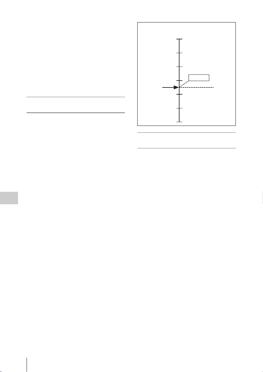
be used for editing or other postprocessing in
1080/23.98PsF format.
Example of quick motion
This example describes shooting at the system
frame frequency of 23.98PsF, recording at 6
frames/second (FPS) and played back at the
system frame frequency of 23.98PsF, it is played
back in quick motion at 24/6 = 4 times normal
playback speed. The recorded tape can be used
for editing or other post-processing in 1080/
23.98PsF format.
Relation between the target frame
frequency and the number of frames shot
To obtain the desired slow and quick motion
effects, it is necessary to set the appropriate
number of frames according to the target frame
frequency. To obtain quick motion effects, shoot
with undercranking. To obtain slow motion
effects, shoot with overcranking.
Example at the target frame frequency of
23.98PsF
To obtain quick motion effects: Set the number
of frames to 1 to 23 FPS.
To obtain slow motion effe cts: Set the number of
frames to 25 to 60 FPS.
For example, shooting at 60 FPS causes playback
in slow motion at 0.4 times normal playback
speed.
Chapter 6 SR Motion (With HKSR-9002 Installed)
Number of frames
(Frames/second)
FPS
60
Slow motion
Target frame
frequency:
23.98PsF
30
24 FPS
Quick motion
Normal
speed
playback
1
Relation between the target frame
frequency and timecode
When the system frequency is 23.98 Hz,
timecode normally advances from 0 to 23 frames.
This becomes the timecode of the recorded
material (target frame frequency). If the rate at
which timecode advances is not constant within
the recorded material, a timecode discontinuity
occurs at playback time. For this reason, set the
target frame rate at recording time to the same
value as the timecode at playback time.
In SR Motion shooting, it is possible to set the
target frame frequency and the system frequency
at recording time to different values. For
example, if 60 frames are recorded with the target
frame frequency set to 23.98 Hz and the system
frequency set to 59.94 Hz, then 60 frames per
second are recorded, but the timecode does not
advance from 0 to 59 frames. Instead, it advances
from 0 to 23 frames, which matches the target
frame frequency. If one second is recorded with
these settings, beginning with second 00 frame
00, then the timecode advances quickly from
second 00 frames 00 to 23, and then continues to
advance as second 01 frames 00 to 23, and finally
as second 02 frames 00 to 11, at which point 60
frames have been recorded (see the following
figure).
100
When a tape recorded in this way is played on a
VTR that has been set to a system frequency of
23.98 Hz (the tape is played at a target frame
frequency of 23.98PsF), then the video is 24/60 =
Overview
 Loading...