

Page 1

HD DIGITAL VIDEOCASSETTE RECORDER
SRW-5000
SRW-5500
FORMAT CONVERTER BOARD
HKSR-5001
DIGITAL BETACAM PROCESSOR BOARD
HKSR-5002
RGB PROCESSOR BOARD
HKSR-5003
OPERATION MANUAL [English]
1st Edition (Revised 4)
Page 2
Important Safety Instructions
• Read these instructions.
• Keep these instructions.
• Heed all warnings.
• Follow all instructions.
• Do not use this apparatus near water.
• Clean only with dry cloth.
• Do not block any ventilation openings.
Install in accordance with the manufacturer’s
instructions.
• Do not install near any heat sources such as radiators,
heat registers, stoves, or other apparatus (including
amplifiers) that produce heat.
• Do not defeat the safety purpose of the polarized or
grounding-type plug. A polarized plug has two blades
with one wider than the other. A grounding-type plug
has two blades and a third grounding prong. The wide
blade or the third prong are provided for your safety. If
the provided plug does not fit into your outlet, consult an
electrician for replacement of the obsolete outlet.
• Protect the power cord from being walked on or pinched
particularly at plugs, convenience receptacles, and the
point where they exit from the apparatus.
• Only use attachments/accessories specified by the
manufacturer.
• Use only with the cart, stand, tripod, bracket,
or table specified by the manufacturer, or sold
with the apparatus.
When a cart is used, use caution when moving
the cart/apparatus combination to avoid injury from tipover.
• Unplug this apparatus during lightning storms or when
unused for long periods of time.
• Refer all servicing to qualified service personnel.
Servicing is required when the apparatus has been
damaged in any way, such as power-supply cord or plug
is damaged, liquid has been spilled or objects have fallen
into the apparatus, the apparatus has been exposed to
rain or moisture, does not operate normally, or has been
dropped.
WARNING
To prevent fire or shock hazard, do not
expose the unit to rain or moisture.
To avoid electrical shock, do not open the
cabinet. Refer servicing to qualified
personnel only.
THIS APPARATUS MUST BE EARTHED.
This symbol is intended to alert the user to
the presence of uninsulated “dangerous
voltage” within the product’s enclosure
that may be of sufficient magnitude to
constitute a risk of electric shock to
persons.
This symbol is intended to alert the user to
the presence of important operating and
maintenance (servicing) instructions in
the literature accompanying the
appliance.
WARNING: THIS WARNING IS APPLICABLE
FOR USA ONLY.
If used in USA, use the UL LISTED power
cord specified below.
DO NOT USE ANY OTHER POWER
CORD.
Plug Cap Parallel Blade with ground pin
(NEMA 5-15P Configuration)
Cord Type SJT, three 16 or 18 AWG
wires
Length Minimum 1.5 m (4 ft 11 in), less
than 2.5 m (8 ft 3 in)
Rating Minimum 10 A, 125 V
Using this unit at a voltage other than 120 V
may require the use of a different line cord
or attachment plug, or both. To reduce the
risk of fire or electric shock, refer servicing
to qualified service personnel.
WARNING: THIS WARNING IS APPLICABLE
FOR OTHER COUNTRIES.
1. Use the approved Power Cord (3-core mains lead)/
Appliance Connector/Plug with earthing-contacts that
conforms to the safety regulations of each country if
applicable.
2. Use the Power Cord (3-core mains lead)/Appliance
Connector/Plug conforming to the proper ratings
(Voltage, Ampere).
2
Page 3

If you have questions on the use of the above Power Cord/
Appliance Connector/Plug, please consult a qualified
service personnel.
CAUTION
The apparatus shall not be exposed to dripping or
splashing and no objects filled with liquid, such as vases,
shall be placed on the apparatus.
CAUTION
The unit is not disconnected from the AC power source
(mains) as long as it is connected to the wall outlet, even if
the unit itself has been turned off.
For the customers in U.S.A.
This equipment has been tested and found to comply with
the limits for a Class A digital device, pursuant to Part 15
of the FCC Rules. These limits are designed to provide
reasonable protection against harmful interference when
the equipment is operated in a commercial environment.
This equipment generates, uses, and can radiate radio
frequency energy and, if not installed and used in
accordance with the instruction manual, may cause
harmful interference to radio communications. Operation
of this equipment in a residential area is likely to cause
harmful interference in which case the user will be
required to correct the interference at his own expense.
E1 (residential), E2 (commercial and light industrial), E3
(urban outdoors), E4 (controlled EMC environment, ex.
TV studio).
You are cautioned that any changes or modifications not
expressly approved in this manual could void your
authority to operate this equipment.
The shielded interface cable recommended in this manual
must be used with this equipment in order to comply with
the limits for a digital device pursuant to Subpart B of Part
15 of FCC Rules.
For the customers in the U.S.A.
This product contains mercury. Disposal of this product
may be regulated if sold in the U.S.A. For disposal or
recycling information, please contact your local authorities
or the Electronics Industries Alliance
(www.eiae.org http://www.eiae.org ).
Do not install the appliance in a confined space, such as
book case or built-in cabinet.
For the customers in Europe
This product with the CE marking complies with both the
EMC Directive (89/336/EEC) and the Low Voltage
Directive (73/23/EEC) issued by the Commission of the
European Community.
Compliance with these directives implies conformity to
the following European standards:
• EN60065: Product Safety (For SRW-5000/5500)
• EN55103-1: Electromagnetic Interference (Emission)
• EN55103-2: Electromagnetic Susceptibility (Immunity)
This product is intended for use in the following
Electromagnetic Environment(s):
3
Page 4

Table of Contents
Chapter 1 Overview
1-1 Features ........................................................................... 9
1-1-1 Features of the SRW-5000/SRW-5500............................. 9
1-1-2 Features of the Control Panel.......................................... 11
1-2 Optional Accessories ................................................... 13
1-3 Using the CD-ROM Manual .......................................... 13
1-3-1 CD-ROM System Requirements.....................................13
1-3-2 Preparations.....................................................................13
1-3-3 To Read the CD-ROM Manual.......................................13
Chapter 2 Locations and Functions of Parts
2-1 Control Panel................................................................. 15
2-1-1 Upper Control Panel .......................................................16
2-1-2 Lower Control Panel .......................................................17
2-1-3 System Set-Up Panel.......................................................23
2-2 Connector Panel ........................................................... 24
Chapter 3 Setting Up the VTR
3-1 Connecting External Equipment ................................. 29
3-2 Reference Signals......................................................... 32
3-3 Handling Cassettes....................................................... 34
3-4 Using a Memory Stick................................................... 35
3-1-1 Making HD Digital Connections .................................... 29
3-1-2 Making NTSC/PAL Digital Connections .......................30
3-1-3 Cascade Connection........................................................31
3-2-1 Reference Signals for Output Video ...............................32
3-2-2 Reference Signal Connections ........................................33
3-3-1 Recommended Cassettes................................................. 34
3-3-2 Inserting and Ejecting Cassettes .....................................34
3-3-3 Preventing Accidental Erasure........................................35
3-4-1 Notes on Memory Stick .................................................. 35
4
Table of Contets
Page 5

Chapter 4 Menu Settings
4-1 Registering and Storing Menu Settings ......................37
4-1-1 Menu Configuration ........................................................37
4-1-2 Changing Menu Settings.................................................37
4-1-3 Registering Items to the VTR SETUP Menu..................38
4-1-4 VTR Memory Bank Function .........................................39
4-1-5 Memory Stick Operations ...............................................41
4-1-6 Adding Titles to the Data ................................................46
4-1-7 Details on VTR Memory Bank and Memory Stick
Functions .........................................................................46
4-1-8 Memory Stick Data Compatibility..................................47
4-1-9 Automatic Reading from a VTR Bank at Power On.......47
4-1-10 Saving and Recalling DEFAULT Settings on a Bank ..48
4-1-11 Saving and Recalling DEFAULT Settings in a “Memory
Stick”...............................................................................48
4-2 HOME Menu ...................................................................50
4-2-1 Selecting the Output Signals (PB/EE).............................51
4-2-2 Record Inhibit Mode (REC INH)....................................51
4-2-3 Selecting the Edit Mode and Edit Channel (ASSEMBLE,
INS TC, INS VIDEO, INS AUDIO and INS CUE)........51
4-2-4 Preread Settings (PRE READ)........................................52
4-2-5 Still-Picture Output (FREEZE).......................................52
4-2-6 Setting the Preroll Time (PREROLL TIME)..................52
4-2-7 Selecting DMC Playback (DMC) ...................................52
4-2-8 Setting the Stop Code (STOP CODE) ............................53
4-3 TC Menu .........................................................................56
4-3-1 Setting the Time Data (TIMER SEL/RESET/SET/HOLD)
57
4-3-2 Setting the Time Code Reader (TCR SEL).....................60
4-3-3 Setting the Time Code Generator (TCG SOURCE/MODE)
60
4-3-4 Selecting the Time Code Running Mode (RUN MODE) ...
60
4-3-5 Selecting the Drop Frame Mode (DF/NDF) ...................61
4-3-6 Selecting the Content of the Second Time Code Display
Area (TC2 SEL) ..............................................................61
4-3-7 Selecting CTL Display Mode (TAPE TIMER) ..............61
4-3-8 Presetting Pulldown Time Code (PDPSET MENU)
(when HKSR-5001 is installed) ......................................61
4-3-9 Presetting for Conversion from Frame Time Code
(TCCONV MENU) .........................................................62
4-3-10 Displaying the Pulldown Time Code (PDTC DISP) (when
HKSR-5001 is installed) .................................................64
Table of Contets
5
Page 6

4-3-11 Superimposition of Character Information (PD CHARA/
CHARA SUPER/H-POS/V-POS)...................................64
4-4 CUE Menu ...................................................................... 68
4-4-1 Selecting a Multi-Cue Mode........................................... 69
4-4-2 Registering Cue Points....................................................69
4-4-3 Erasing Cue Point Data...................................................71
4-4-4 Prerolling to a Cue Point.................................................71
4-4-5 Changing a Cue Point Into an Edit Point........................ 72
4-4-6 Backspace Editing........................................................... 72
4-4-7 TELE FILE Menu ...........................................................72
4-5 VIDEO Menu .................................................................. 87
4-5-1 Selecting the Reference Signal (SERVO REF) .............. 88
4-5-2 Adjusting the Output Video Signal (MASTER to FINE)...
88
4-6 AUDIO Menu .................................................................. 91
4-6-1 Selecting the Audio Input Signal (AUDIO IN) ..............92
4-6-2 Digital Audio Output Signal Source Track Selection
(DIGOUT EXCHNG) .....................................................92
4-6-3 Analog Audio Output Signal Source Track Selection
(ANAOUT EXCHNG)....................................................93
4-6-4 Digital Audio Output Signal Source Track Selection
(SDOUT EXCHNG) .......................................................93
4-6-5 Audio Transition Type Selection for Digital Audio Editing
(AUDIO EDIT) ...............................................................94
4-6-6 Fade Processing Time Selection for Digital Audio Editing
(FADE TIME)................................................................. 94
4-6-7 External Device Digital Audio Edit Preset Command
Replace Mode Selection (AUDIO EDIT PRESET
REPLACE)......................................................................95
4-6-8 External Device Analog Audio Edit Preset Command
Replace Mode Selection (ANALOG AUDIO EDIT
REPLACE)......................................................................95
4-6-9 PITCH GROUP Selection (PITCH CORRECTION
GROUP SELECT) .......................................................... 95
4-7 SET UP Menu................................................................. 97
4-7-1 VTR SETUP Menu .........................................................98
4-7-2 PANEL SETUP Menu ..................................................100
Chapter 5 Recording/Playback
5-1 Preparing for Recording............................................. 102
6
Table of Contets
5-1-1 Setting Switches and Menus .........................................102
5-1-2 Selecting Audio Signals................................................ 103
5-1-3 Adjusting the Recording Level .....................................104
Page 7

Chapter 6 Editing
5-1-4 Simultaneously Monitoring Playback of Video and Audio
Signals Being Recorded ................................................105
5-1-5 Audio Level Meter Display Modes...............................105
5-2 Recording.....................................................................106
5-3 Preparing for Playback ...............................................107
5-3-1 Setting Switches and Menus .........................................107
5-3-2 Adjusting the Audio Playback Level ............................107
5-3-3 Selecting the HD-SD Conversion Mode .......................108
5-4 Playback.......................................................................109
5-4-1 Normal-Speed Playback................................................109
5-4-2 Variable Speed Playback...............................................109
5-4-3 Capstan Override Playback ...........................................111
5-4-4 DMC Playback ..............................................................111
5-4-5 Playing Back Non-audio Data.......................................112
5-4-6 Performing Program Play..............................................113
6-1 Basic Automatic Editing .............................................115
6-1-1 Overview of Automatic Editing ....................................115
6-1-2 Setting Switches and Menus .........................................116
6-1-3 Selecting the Edit Mode ................................................117
6-1-4 Setting Edit Points.........................................................117
6-1-5 Editing Non-audio Data ................................................120
6-1-6 Confirming Edit Points .................................................120
6-1-7 Cuing Up and Prerolling ...............................................121
6-1-8 Previewing.....................................................................121
6-1-9 Modifying Edit Points...................................................122
6-1-10 Performing Automatic Editing....................................124
6-2 Advanced Automatic Editing......................................126
6-2-1 DMC Editing.................................................................126
6-2-2 Animation Editing.........................................................127
6-2-3 Preread Editing..............................................................127
6-3 Manual Editing.............................................................129
Appendix
Maintenance .......................................................................130
Head Cleaning.........................................................................130
Moisture Condensation...........................................................130
Specifications ...................................................................131
Table of Contets
7
Page 8

Error Messages and Warning Messages ........................ 134
Error Messages ....................................................................... 134
Warning Messages.................................................................. 135
Error Log Menu ......................................................................137
Glossary............................................................................. 139
Menu List ........................................................................... 141
Items Relating to VTR Operations (Nos. 001 to ...)...............141
Items Relating to Operation Panels (Nos. 101 to ...).............. 145
Items Relating to Remote Interface (Nos. 201 to ...)..............148
Items Relating to Editing (Nos. 301 to ...)..............................149
Items Relating to Prerolling (Nos. 401 to ...) .........................152
Items Relating to Recording Protection (Nos. 501 to ...) .......153
Items Relating to the Time Code (Nos. 601 to ...).................. 154
Items Relating to the Video Control (Nos. 706 to ...).............158
Items Relating to the Audio Control (Nos. 807 to ...) ............ 162
Items Relating to Digital Processing (Nos. 902 to ...)............ 172
Items Relating to the Pulldown Control (Nos. A01 to ...) ......176
Other Items (Nos. T01 to ...)...................................................178
Index................................................................................... 183
8
Table of Contets
Page 9

Overview
1-1 Features
1-1-1 Features of the SRW-5000/ SRW-5500
The SRW-5000/SRW-5500 is a high-definition digital
videocassette recorder using the HDCAM-SR format. It is
a small and light unit incorporating LSIs for signal
processing and is comparable to the HDCAM
HDW-F500 in size, weight and functionality.
The SRW-5500 only is a recorder supporting both the
HDCAM-SR and HDCAM formats.
1) HDCAM is a trademark of Sony Corporation.
HDCAM-SR format
The HDCAM-SR format exploits technological advances
in signal processing and magnetic recording, to provide
functionality comparable to that of the HDCAM format,
while offering HD digital recording and playback with
high image and sound quality.
The technology incorporated in this unit includes the
following.
• Highly efficient and mild data compression using newly
developed MPEG-4 Studio Profile
• Powerful error-correcting codes
• High-performance, high-accuracy heads and drum with
dynamic tracking (DT ™), together with a new autotracking technique, yielding highly reliable narrow track
recording and playback.
These technologies allow 120 minutes of recording on an
HDCAM-SR cassette (L type), the same size as the
HDCAM cassette.
Digital signal processing
In this unit, 4:2:2 component video signals obtained by
quantization according to ITU-R709, SMPTE 274M and
BTA S-002B (SMPTE 260M) are compressed using
MPEG-4 Studio Profile. Audio signals are processed
uncompressed, according to the AES/EBU format.
1)
model
Chapter
Input interface
The input interface is based on the HD SDI (HD Serial
Digital Interface) format specified by BTA S-004B/005B/
006B (SMPTE 291M/292M/299M) and ARIB STD-B4,
allowing a single BNC coaxial cable to carry one
component video signal, twelve digital audio channels,
and time code in time division multiplex; this is separated
for conversion to parallel data.
Audio recording can be switched between the digital audio
signal multiplexed with the HD SDI signal and the audio
signal from an AES/EBU digital interface.
Bit rate reduction encoder
The component video signal undergoes frame shuffling. It
is then compressed by a process in which it is subjected to
DCT (discrete cosine transform) or DPCM (differential
pulse code modulation), quantization control, and variable
length word encoding. This is the core of the newly
developed MPEG-4 Studio Profile. Interlaced signals are
compressed in fields and progressive signals are
compressed in frames.
ECC encoder
The outer ECC (Error Correction Code) is added to the
compressed video and audio data, followed by the inner
ECC, ID data, and sync data. Reed-Solomon codes are
employed in this error correction system.
Channel coding
Video and audio data with the ECC added is recorded in
the form of serial data. The HDCAM-SR format adopts a
scrambled i-NRZ channel coding system, giving
consideration to off-track and noise characteristics.
Playback signal processing
The playback digital signal is equalized by an equalizer
circuit. It then passes powerful inner and outer ECCs
which can correct dropouts in the reproduced signal. It
further goes through an error concealment circuit to have
errors still remaining in the signal rectified.
Output interface
Component video data is converted into serial data and
multiplexed with audio data and time code, then output in
the HD SDI format.
1
Chapter 1 Overview
1-1 Features
9
Page 10

With an HD-SD converter board installed, the unit can
output both D1 SDI and analog composite signals.
Besides audio data is output as digital data multiplexed
with the HD SDI signal, it is also output via an AES/EBU
digital interface. Analog data converted from digital data is
also provided.
Chapter 1 Overview
HDCAM format
The HDCAM format uses tape with the same 12.65 mm
width as the Betacam series to enable recording of up to
two hours of high-quality HD video. Video signal
compression uses prefilter and coefficient recording
technology.
Advanced recording and playback
functions
High-quality digital recording
This unit uses a component system to record video signals.
An AES/EBU format with a wide dynamic range is used
for 12-channel audio recording. A unique and powerful
error correction circuit and concealment circuit are used in
digital signal processing.
Accurate and stable video signal output is made possible
by setting and adjusting the internal digital video
processor.
Record/playback modes
HDCAM-SR format (SRW-5000/5500) or HDCAM
format (SRW-5500)
As the record/playback mode, you can select from the
following ten modes.
1080×1920: 59.94i/60i/50i/23.98PsF/24PsF/25PsF/
29.97PsF/30PsF
720×1280: 59.94P/50P (HDCAM-SR format only)
Playback compatibility
You can select the following compatibility playback
functions.
• HDCAM (SRW-5000)
1080×1920: 59.94i/60i/50i/23.98PsF/24PsF/25PsF/
29.97PsF/30PsF
• Digital Betacam
525/59.94i, 625/50i
However, Digital Betacam playback requires the
HKSR-5002 (option).
Internal format conversion function
By installing an optional HKSR-5001, when the operation
mode of this unit is 23.98PsF or 24PsF, a 59.94i or 60i
mode HD SDI output (audio/VITC multiplex) is made
available. Additionally, conversion in either direction
between 1080×1920 and 720×1280, and conversion from
4:2:2 signal to 4:4:4 signal is possible, and with the
additional installation of an HKSR-5003, conversion from
a 4:4:4 signal to a 4:2:2 signal.
Noiseless playback with DT heads
When using the HDCAM-SR or HDCAM format, the
dedicated playback DT heads allow you to perform
noiseless playback in the range from –1 to +2 times normal
speed, including still-picture playback. When using the
Digital Betacam format, the playback range is from –1 to
+3. However, Digital Betacam playback requires the
HKSR-5002 (option).
Video and audio confidence heads
Video and audio (channels 1 through 12, or 4 channels for
the HDCAM format (SRW-5500 only)) signals can be
recorded and simultaneously played back to check the
recording.
Internal time code generator and reader
The internal time code generator allows you to record time
code (LTC or user bits) together with video and audio
signals. Time codes (LTC or user bits) can be read during
playback using the time code reader.
Computer servo system
Computer-controlled servo motors provide direct drive for
the drum, capstan, and two reels, enabling quick and
accurate tape access.
Capstan override function
You can adjust the playback speed by ±15% to ensure
synchronization between, for example, two VTRs playing
back the same program.
Independent audio level control
It is possible to adjust the recording and playback levels
either independently on each channel or simultaneously on
all 12 channels (or 4 channels for HDCAM format (SRW5500 only)) while monitoring the peak values.
Tele-File
1)
memory label system
This unit incorporates the Tele-File memory label system
to allow users to read, write and update videocassette
management information, log data (IN/OUT points) and
cue point data on memory labels, providing greater
efficiency in cassette management and editing.
1) Tele-File
A contact-free system for writing, reading, and modifying video cassetterelated information on IC memory-bearing labels. Tele-File is a trademark
of Sony Corporation.
Program Play (P-PLAY) Function/Pitch
Correction Function
Program play is a function that allows play at ±5% of
normal speed. Pitch correction of the audio is possible at
the same time.
This function is available only for the combination of
SRW-5000/5500 Serial No. 12001 or higher and HKSR5001 Serial No. 11001 or higher.
10
1-1 Features
Page 11

Features for ease of operation
Compact, lightweight, low power consumption
The VTR is small and light enough to be used in outside
broadcast vans or in EFP (Electronic Field Production)
assignments.
Remote control operation
The VTR has a serial RS-422A 9-pin connector to allow
control of the VTR by an external control unit.
The VTR also comes with 9-pin REMOTE 1-IN(9P) and
REMOTE 1-I/O(9P) connectors to support bridge
connection of multiple SRW-5000/5500 units or other
VTRs equipped with 9-pin remote connectors for
simultaneous operation. Furthermore, you can control the
VTR from an external control unit with a parallel (50-pin)
interface.
Digital hours meter
The meter can show the total elapsed time since the VTR
was turned on, total drum revolution time, total tape
running time and total number of threadings and
unthreadings.
Self-diagnosis
This function allows the VTR to perform self diagnostics
when a malfunction occurs. An error message is displayed
and a history of all errors that have occurred is recorded.
Easy-to-maintain plug-in boards
The VTR uses plug-in circuit boards to simplify servicing
and inspection.
Mountable in standard 19-inch rack
The unit can be mounted in an EIA-standard 19-inch rack.
For rack mounting, refer to the Installation Manual.
1-1-2 Features of the Control Panel
The control panel provides eight menu screens
corresponding to different operation modes to allow fast
and easy adjustment of necessary settings, as well as the
ability to store menu settings to a memory stick for later
recall.
Menu-driven operations for a variety of
purposes
Eight menus are displayed on the 130 × 95 mm
1
(5
/8 inches × 3 3/4 inches) color display and are set using
the 10 function buttons.
You can register desired items to the menus other than the
SET UP menu.
Pressing the [F4] (PF ASSIGN) button in the SET UP
menu displays the menu items that can be registered.
HOME menu
Use this menu to make the basic settings for recording,
playback, and editing operations, and to select channels to
be edited during insert editing.
TC menu
Use this menu to make time code settings.
VIDEO menu
Use this menu to adjust the video signals. The VIDEO
menu screen shows the VTR operation mode, current
position time code, time code type, and so on.
AUDIO menu
Use this menu to adjust the audio signals. The AUDIO
menu screen shows the VTR operation mode, current
position time code, time code type, and so on.
CUE menu
Use this menu to set up to 100 cue points. In page mode,
10 cue points per page can be set on a total of 10 pages. In
the TELE FILE menu, you can change the setting for the
memory label system Tele-File.
PF1/PF2 (Personal Function) menus
Use these menus to register up to 40 of the most frequently
used items from the other menus (up to 10 items each can
be registered to PF1, ALT/PF1, PF2 and ALT/PF2).
SET UP menu
This menu enables the following settings.
• The VTR BANK menu allows up to eight pages of menu
settings to be saved.
• Use the MEMORY CARD menu to store current settings
of the VTR and up to eight pages of the contents of the
VTR memory bank to a memory stick.
• Use the scrollable PF ASSIGN menu to display the items
that can be registered, and to select and register the most
frequently used menu items.
• Use the scrollable VTR SETUP menu to display the
items necessary for making initial settings, and to
directly change settings without registering them with
the function buttons for each menu.
• Use the PANEL SETUP menu to set control panel
operations, such as the keyboard sound output.
MAINTENANCE menu
Use this menu to access the maintenance functions.
For details, refer to the Maintenance Manual Volume 1.
A full complement of storage/recall
functions
These functions allow you to use titles to store and recall
menu settings in either the VTR’s internal memory banks
or memory sticks.
Chapter 1 Overview
1-1 Features
11
Page 12

VTR memory banks
These memory banks allow you to store up to eight pages
of VTR settings in addition to the current VTR settings.
Factory settings are also stored here, allowing the VTR to
be reset to these values at any time.
Chapter 1 Overview
Memory sticks
Each memory stick can hold the current VTR settings as
well as up to eight pages of settings. A single memory stick
thus allows you to store and recall the entire contents of the
VTR memory banks.
Title function
This function allows you to add titles when storing data to
the VTR memory bank or memory stick, thus facilitating
data retrieval and management.
Write protect function
Setting pages stored in VTR memory banks or memory
sticks can be write protected on an individual basis.
A full range of editing functions
Two SRW-5000/5500 units can be connected allowing
automatic or manual assembe and insert editing. The VTR
also features a full range of editing functions, including
preview, review, preroll, and the setting or changing of edit
points.
Digital time counter
The time counter display shows CTL and time codes
(LTC/VITC
1)
), or user bits data for precise setting of edit
points.
1) LTC (Longitudinal Time Code):
Time code recorded on a longitudinal track
VITC (Vertical Interval Time Code):
Time code recorded on a video track during the vertical blanking interval
Quick access to edit points
The following methods are provided for the setting of edit
points:
• Multi-cuing for up to 100 edit points
• Search dial with shuttle and jog functions
• Direct input through numeric buttons
DMC (Dynamic Motion Control) editing
Using the DT
®
(Dynamic Tracking) heads, you can play
back a section of an edit at speeds between –1 and +2 times
normal speed and store the speed variation in memory for
later use in automatic editing.
Split editing
In insert mode, audio and video edit points can be set
separately.
Preread editing
Video and audio signals that have been pre-read can be
externally processed and simultaneously re-recorded.
A variety of audio editing modes
You can select cut-in editing, cross-fade editing, and fade
in/out editing for the audio signals.
Display of duration between edit points
The duration between any two of IN, OUT, AUDIO IN, or
AUDIO OUT points can be displayed by simultaneously
pressing two buttons corresponding to those edit points.
12
1-1 Features
Page 13

1-2 Optional Accessories
The following accessories can be used with this unit.
HKSR-5001 Format Converter Board
This allows format conversion described below:
• 2-3 pulldown (23.98PsF to 59.94i, 24PsF to 60i)
• Conversion between 1080 and 720P
• 4:2:2 between 4:4:4
(Conversion of 4:4:4 to 4:2:2 is possible only when the
HKSR-5003 is additionally installed.)
1-3 Using the CD-ROM Manual
Chapter 1 Overview
The supplied CD-ROM includes operation manuals for
this unit (English, Japanese, French and German versions).
1-3-1 CD-ROM System Requirements
HKSR-5002 Digital Betacam Processor Board
This allows you to play back Digital Betacam tapes and
output SD and HD signals.
When the system is operated in 4:4:4 mode, up conversion
of the output to HD signals are possible as follows,
depending on the system setting.
1080: Up conversion to 1080.
720: Up conversion to 720P.
When the system is operated in 4:4:4 mode, no upconverted HD output can be obtained.
HKSR-5003 RGB Processor Board
This allows you to accept dual link HD SDI input, and
record and play back RGB (4:4:4).
HKDV-900 HD Digital Video Controller
This allows you to remotely control the parameters for
video signals and image enhancement.
References
In addition to this Operation Manual, the following
manuals are available:
Maintenance Manual Volume 1 (optional)
Provides detailed information necessary to maintain the
VTR.
Maintenance Manual Volume 2 (optional)
Provides information on spare parts.
The following are required to access the supplied CDROM disc.
• Computer: PC with Intel Pentium CPU.
- Installed memory: 64 MB or more
-CD-ROM drive: × 8 or faster
• Monitor: Monitor supporting resolution of 800 × 600
dots or higher
• Operating system: Microsoft Windows XP Professional
or Windows XP Home Edition
When these requirements are not met, access to the CDROM disc may be slow, or not possible at all.
1-3-2 Preparations
The one of following software must be installed on your
computer in order to use the operation manuals contained
in the CD-ROM disc.
• Adobe Acrobat Reader 4.0 or higher
• Adobe Reader Version 6.0 or higher
Note
If Adobe Reader is not installed, it may be downloaded
from the following URL:
http://www.adobe.com/
Maintenance Manual Volume 3 (optional)
Contains circuit diagrams and block diagrams.
Installation Manual (supplied)
Provides necessary information to install and operate the
VTR.
For information about changing the video system, refer to
“1-11. System Setting” in the Installation Manual.
9-pin Protcol Manual (optional)
Provides information on the 9-pin protocol.
1-3-3 To Read the CD-ROM Manual
To read the operation manual contained in the CD-ROM
disc, do the following.
1
Insert the CD-ROM disc in your CD-ROM drive.
A cover page appears automatically in your browser.
If it does not appear automatically in the browser,
double click the index.htm file on the CD-ROM disc.
2
Select and click the operation manual that you want to
read.
This opens the PDF file of the operation manual.
1-2 Optional Accessories / 1-3 Using the CD-ROM Manual
13
Page 14

Note
If you lose the CD-ROM disc or become unable to read its
content, for example because of a hardware failure, you
can do the following.
• You can purchase a new CD-ROM disc to replace one
Chapter 1 Overview
that has been lost or damaged. Contact a Sony service
representative.
14
1-3 Using the CD-ROM Manual
Page 15
Locations and Functions
of Parts
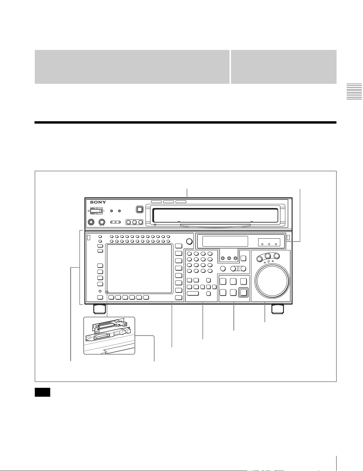
2-1 Control Panel
The control panel consists of the following sections:
• Upper control panel
Chapter
• Lower control panel
• System set-up panel
Upper control panel 4 Display section
SRW-5000
HD DIGITAL VIDEO CASSETTE RECORDER
HD DIGITAL VIDEO CASSETTE RECORDER
SRW-5000
2
(see page 20)
Chapter 2 Locations and Functions of Parts
1 Menu control section (see page 17)
Lower control panel
Note
Normally operate the unit with the control panel closed.
For details of how to open the control panel, for example
for system setup, refer to the Maintenance Manual.
System set-up panel: Access by opening the lower control panel (see page 23)
5 Search control section
3 Tape transport control section (see page 20)
2 Editing control section (see page 19)
(see page 22)
2-1 Control Panel
15
Page 16
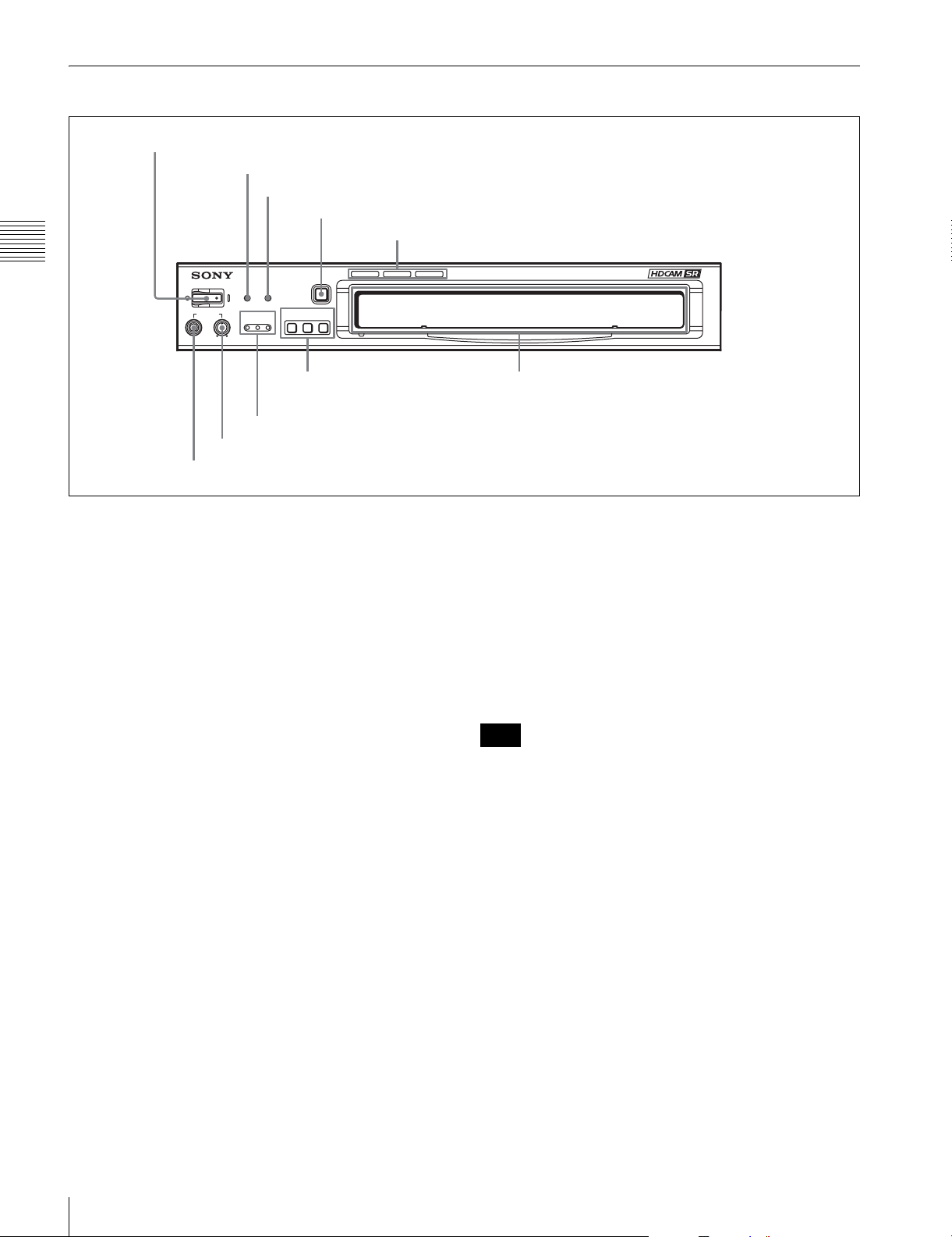
2-1-1 Upper Control Panel
SRW-5000
HD DIGITAL VIDEO CASSETTE RECORDER
1 POWER switch
2 ERROR indicator
3 WARNING indicator
Chapter 2 Locations and Functions of Parts
POWER
ERROR WARNING
PHONES
CHANNEL
CONDITION
4 EJECT button
EJECT
REMOTE
ETHERNET
1(9P) 2(50P)
5 Format indicators
6 REMOTE buttons
7 CHANNEL CONDITION indicators
8 PHONES level control
9 PHONES jack
a POWER switch
Pressing on the ‘(’ side of this switch powers the unit and
lights up the information display (see page 20) and color
display (see page 18). To turn the unit off, press on the ‘a’
side of the switch.
b ERROR indicator
This lights when a serious problem occurs, such as an
operational malfunction or system internal error.
You can check the details on the lower control panel.
For details, see “Error Messages and Warning Messages”
on page 134.
c WARNING indicator
This flashes when there is a fault in the unit. You can check
the details on the lower control panel.
For details, see “Error Messages and Warning Messages”
on page 134.
d EJECT button
Pressing this button automatically ejects the cassette after
several seconds.
e Format indicators (Digital BETACAM/HDCAM/
HDCAM SR)
These show the format of the cassette loaded into the unit.
f REMOTE buttons
Press one of the following buttons, to select how the VTR
is controlled.
Cassette compartment
ETHERNET: This button lights when pressed, enabling
access from the network connected to the
ETHERNET connector on this unit.
1(9P): This button lights when pressed, enabling this unit
to be controlled from a device connected to the
REMOTE 1-IN(9P) connector or REMOTE 1-I/
O(9P) connector.
2(50P): This button lights when pressed, enabling this unit
to be controlled from a device connected to the
REMOTE 2 PARALLEL I/O(50P) connector.
Note
When the VTR is being controlled by the external
equipment connected to the REMOTE 1-IN(9P) or
REMOTE 2 PARALLEL I/O(50P) connector, all tape
transport buttons and edit operation buttons are disabled,
except the STOP and EJECT buttons. You may also
specify the disabling or enabling of all buttons by setting
the VTR SETUP menu item 008 “LOCAL FUNCTION
ENABLE”.
g CHANNEL CONDITION indicators
These show the status of the playback signal.
Blue: The playback signal status is satisfactory.
Yellow: The playback signal is somewhat degraded, but
playback is possible.
However, if this indicator remains lit continuously,
head cleaning is required.
Red: The playback signal has deteriorated.
If this indicator remains lit continuously, head
cleaning or internal inspection is required.
16
2-1 Control Panel
Page 17
h PHONES level control
Adjusts the output level to the PHONES jack.
For details, see “5-1-2 Selecting Audio Signals” on
page 103.
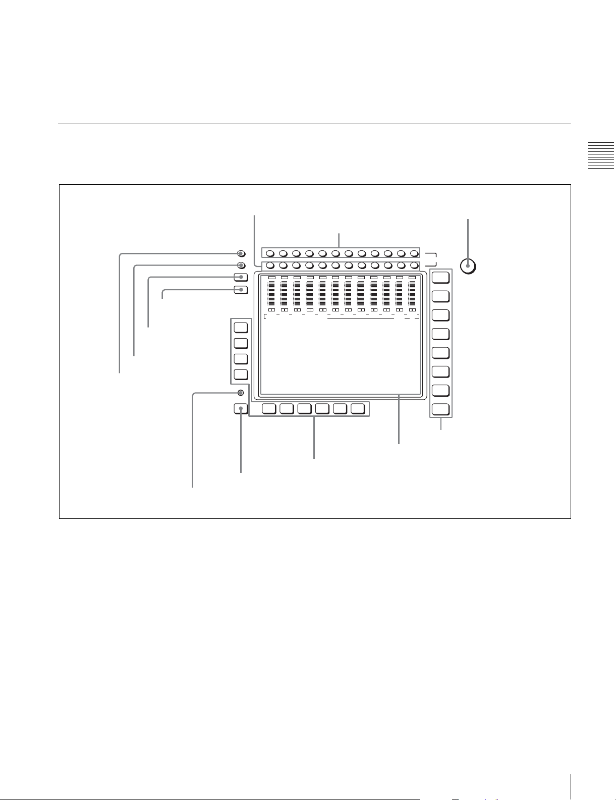
2-1-2 Lower Control Panel
i PHONES jack
Connect stereo headphones with 8 Ω impedance for audio
monitoring during recording, playback, and editing.
Adjust the headphone output level with the PHONES level
control.
1 Menu control section
9 DISPLAY button
0 FULL/FINE button
qa PB LEVEL button
qs REC LEVEL button
8 DIAG button
1 MONITOR R buttons
OVER
OVER
dB
-10
-20
-30
-40
OVER
dB
dB
0
0
0
-10
-10
-20
-20
-30
-30
-40
-40
L
L
L
R
R
CH1
CH2
CH3
EDIT PRESET VIDEO TC
F1
F2
F3
F4
DIAG
F5ALT F6 F7 F8 F9 F10
7 ALT button
2 MONITOR L buttons
OVER
OVER
OVER
dB
dB
0
-10
-10
-20
-20
-30
-30
-40
-40
L
R
R
CH4
OVER
dB
dB
0
0
0
-10
-10
-20
-20
-30
-30
-40
-40
L
L
L
R
R
CH5
CH6
CH7
6 Function buttons
Chapter 2 Locations and Functions of Parts
3 MULTI CONTROL knob
HOME
TC
VIDEO
AUDIO
CUE
PF1
PF2
SET UP
MULTI
CONTROL
L
MONITOR
CH12CH11CH10CH9CH8CH7CH6CH5CH4CH3CH2CH1
R
OVER
OVER
OVER
OVER
0
L
CH10
OVER
dB
dB
0
0
-10
-10
-20
-20
-30
-30
-40
-40
L
L
R
R
R
CH11
CH12
dB
dB
dB
0
0
-10
-10
-10
-20
-20
-20
-30
-30
-30
-40
-40
-40
L
L
R
R
R
CH8
CH9
4 Menu selection buttons
5 Color display
a MONITOR R buttons
Select the audio signal output from the MONITOR
OUTPUT R connector. This assigns the desired channel to
the MONITOR OUTPUT R connector. If you assign more
than one channel to the same monitor output connector, a
mixed audio signal is output.
You can also make this setting using the VTR SETUP
menu item 808 “AUDIO MONITOR-R select”.
In the audio playback level adjustment mode, this is used
to select the channel to be adjusted.
b MONITOR L buttons
Select the audio signal output from the MONITOR
OUTPUT L connector. This assigns the desired channel to
the MONITOR OUTPUT L connector. If you assign more
than one channel to the same monitor output connector, a
mixed audio signal is output.
You can also make this setting using the VTR SETUP
menu item 807 “AUDIO MONITOR-L select”.
In the audio playback level adjustment mode, this is used
to select the channel to be adjusted.
c MULTI CONTROL knob
Used to set the audio recording/playback level and make
settings in the SET UP menu (see page 97).
d Menu selection buttons
These select the menu screen displayed on the display.
HOME button: Press this to go to the HOME menu
screen. The home menu provides settings for the basic
VTR operations and editing operations.
TC button: Press this to go to the TC (time code) menu
screen. In the time code menu, you can switch LTC/
2-1 Control Panel
17
Page 18

VITC, switch DF/NDF, set the time code to be
displayed on an external monitor, and so on.
VIDEO button: Press this to go to the VIDEO menu
screen. Use it to make video related settings.
AUDIO button: Press this to go to the AUDIO menu
screen. Use it to make audio related settings.
CUE button: Press this to go to the CUE menu screen.
The cue menu provides 10 pages to set cue points.
You can set up to 10 cue points per page. You can also
make settings for the Tele-File memory label system.
PF1 button: Press this to go to the PF1 (personal function
Chapter 2 Locations and Functions of Parts
1) menu screen. You can register frequently-used
items in the PF1 menu. The factory default setting is
blank.
PF2 button: Press this to go to the PF2 (personal function
2) menu screen. You can register frequently-used
items in the PF2 menu. The factory default setting is
blank.
SET UP button: Press this to go to the SET UP menu
screen. The setup menu provides functions to save
menu settings in VTR banks or save to a memory
stick, registration operations in the PF buttons, VTR
SETUP menu settings, and so on.
For details of menus, see Chapter 4 “Menu Settings” on
page 37.
e Color display
This comprises principally the audio level display and
menu display.
Audio Level display:
In recording mode or E-E mode
1)
, this displays the audio
recording levels.
In playback mode or CONFI mode, this displays the
playback levels.
The display mode can be changed with the FULL/FINE
button. The factory default display is a reference level of
–20 dB, and peak level 0 dB.
Menu display:
This displays the menu screen selected by the menu
selection buttons.
Each menu screen shows the functions assigned to the
function buttons ([F1] to [F10]), and shows simultaneously
information required for time code display settings and so
on.
h DIAG (diagnostic) button
Hold down the SFT button (see page 19) in the editing
control section and press this switch to switch to the DIAG
menu.
i DISPLAY button
This displays the down-converted output signal in the
whole color display.
Notes
• Depending on the system settings, it may not be possible
to output some signals.
• This function is for a quick check of the output signal,
and cannot be used as a monitor.
j FULL/FINE button
This selects the audio level meter display range.
FULL: The audio level meter display is from –60 dB to 0
dB, or –40 dB to +20 dB. Select which of these ranges
(peak level: 0 dB or +20 dB) is displayed in the VTR
SETUP menu item 814 “LEVEL METER SCALE”.
FINE: The audio level meter display range is expanded,
and displayed with a scale in steps of 0.25 dB. The
reference marker LED at the center of the level meter
display range lights. When the audio level exceeds the
maximum display range, the top OVER display
flashes. When under the minimum display range, the
bottom line flashes.
k PB (playback) LEVEL button
Press this button to enter the playback audio level
adjustment mode. In this mode, you can use the
MONITOR R button to select the adjustment target
channels from channels 1 to 12. While watching the audio
level meter, turn the MULTI CONTROL knob for a
desired audio level.
Clicking the MULTI CONTROL knob resets the playback
audio level to the factory set level (a reference level of 0
dB is displayed for a +4 dBm input). Clicking the MULTI
CONTROL knob again restores the adjusted level.
Press this button again to exit from the playback audio
level adjustment mode, and the MONITOR L and R
buttons return to the normal status (this status is called the
“MONITOR SELECT mode”).
1) E-E mode
An abbreviation fo r Electric-to-Electric mode. In t his mode, video o r audio
input signals are passed and output only through the VTR’s internal
circuitry, and not through the magnetic conversion system comprising tape
and heads.
f Function buttons
Activates the functions in each menu.
g ALT (alternative) button
Press to change the items displayed on the current menu.
Press again to return to the original items.
18
2-1 Control Panel
l REC (recording) LEVEL button
Press this button to enter the recording audio level
adjustment mode. In this mode, you can use the
MONITOR L button to select the adjustment target
channels from channels 1 to 12. While watching the audio
level meter, turn the MULTI CONTROL knob for a
desired audio level.
Clicking the MULTI CONTROL knob resets the recording
audio level to the factory set level (a reference level of 0
dB is displayed for a +4 dBm input). Clicking the MULTI
CONTROL knob again restores the adjusted level.
Page 19
Press this button again to exit from the recording audio
level adjustment mode, and the MONITOR L and R
buttons return to the normal status (this status is called the
“MONITOR SELECT mode”).
2 Editing control section
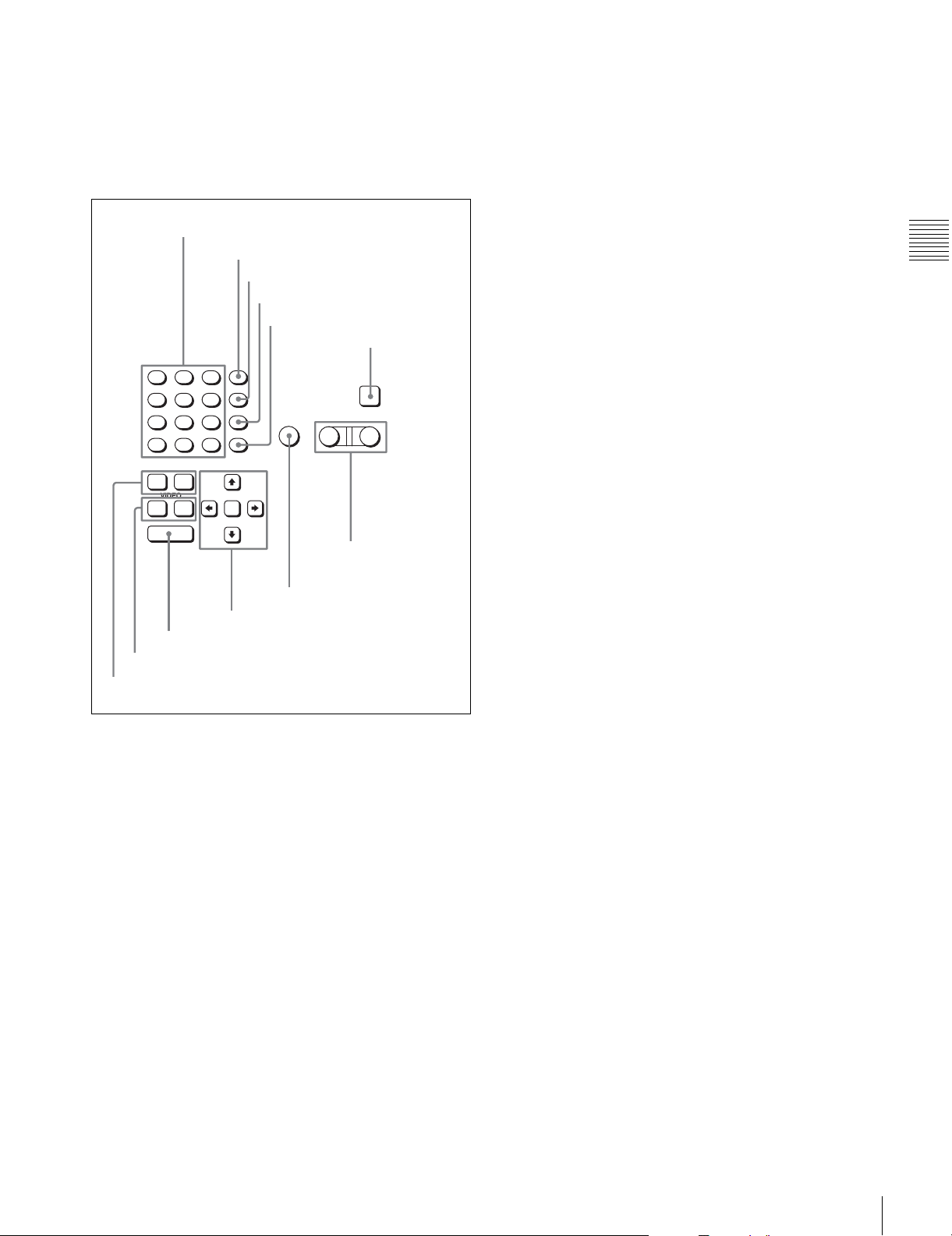
1 Numeric buttons and +/– buttons
2 SFT button
3 RCL button
4 CLR button
5 SET button
6 INPUT CHECK
button
8
7
F
E
5
4
C
B
2
1
A
+
0
AUDI O
IN OUT
VIDEO
IN OUT
ENTRY
0 ENTRY button
qa IN/OUT buttons
qs AUDIO IN/AUDIO OUT buttons
SFT
9
RCL
6
D
CLR
3
SET
–
9 Cursor buttons
AUTO
8 AUTO button
a Numeric buttons and +/– buttons
Press to input time data or edit points data at the cursor
position in menu display. Press buttons 0 to 5 while
holding down the SFT button to input hexadecimal A to F
for user bits. Use the +/– buttons to increase or decrease
settings.
INPUT
CHECK
PLAYER RECORDER
7 PLAYER/
RECORDER
buttons
f INPUT CHECK button
While you hold down this button, the input signal is output
from the monitor output connector, so that you can monitor
the input video and audio.
When the LTC/VITC time code is shown on the display,
you can check the time code generator.
g PLAYER/RECORDER buttons
Select which VTR is to be controlled by this VTR’s control
panel during editing when this VTR is used as a recorder
and an external VTR is connected to the REMOTE 1IN(9P) or REMOTE 1-I/O(9P) connector as a player.
PLAYER: The tape transport buttons and editing
operation buttons on the control panel control the
external player VTR.
RECORDER: The tape transport buttons and editing
operation buttons on the control panel control the
recorder VTR (this VTR).
The PLAYER/RECORDER buttons have no effect when
using this VTR alone.
h AUTO button
When this button is pressed, it lights up and auto edit mode
is activated.
i Cursor buttons
Use to move the cursor (shown in reverse video) on the
display. Also use to change menu settings.
j ENTRY button
Press to enter an edit or cue point.
While holding down this button, press either the AUDIO
IN or AUDIO OUT button, or the IN or OUT button.
k IN/OUT buttons
To set a IN or OUT point during editing, press either of
these buttons while holding down the ENTRY button.
l AUDIO IN/AUDIO OUT buttons
To set an AUDIO IN or AUDIO OUT point during insert
editing, press either of these buttons while holding down
the ENTRY button.
Chapter 2 Locations and Functions of Parts
b SFT (shift) button
Press buttons 0 to 5 while holding down this button to
input hexadecimal A to F for user bits.
Use also in combination with other buttons to perform
other operations.
c RCL (recall) button
Press to recall the previous setting, etc.
d CLR (clear) button
Press to clear input data.
e SET button
Press to finalize input data.
2-1 Control Panel
19
Page 20
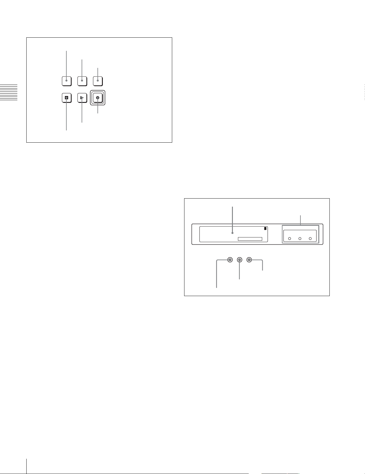
3 Tape transport control section
1 STANDBY button
2 PREROLL button
3 PREVIEW/REVIEW button
PREVIEW/
REVIEW
PREROLLSTANDBY
REC/EDIT
PLAYSTOP
Chapter 2 Locations and Functions of Parts
4 REC/EDIT button
5 PLAY button
6 STOP button
a STANDBY button
Press this button in other than standby mode to make it
light up and place the VTR in standby mode. The head
drum rotates in standby mode, thereby shortening the time
required for the tape to start.
Press this button while in standby mode to turn the button
off and exit from standby mode. The head drum stops
rotating and the tape tension is released. If the VTR
remains in standby mode for more than eight minutes
(factory setting), standby mode is automatically canceled
in order to safeguard the tape.
b PREROLL button
Press to run the tape to the preroll point (a position factory
set to five seconds before the IN point).
Press this button while holding down the IN, OUT,
AUDIO IN or AUDIO OUT button to cue up the tape at the
corresponding edit point.
For details on changing the preroll time, see “4-2-6
Setting the Preroll Time (PREROLL TIME)” on page 52.
c PREVIEW/REVIEW button
After the edit points are set, press this button to preview,
on the monitor connected to the recorder, the effect of the
edit before it is performed. In this operation, the tape runs,
but no editing is carried out.
If you press this button after carrying out an edit, the
results of the edit are played back on the monitor
connected to the recorder.
d REC/EDIT (recording/edit) button
Press this button while holding down the PLAY button to
start recording.
If you press this button in play mode, manual editing
begins. After setting edit points, if you press this button
while the AUTO button is lit, automatic editing is
performed.
e PLAY button
Press to start playback.
Press this button while holding down the REC/EDIT
button to start recording.
Pressing this button during recording or manual editing
changes the VTR to playback mode.
f STOP button
Press this button to stop recording or playback.
When you insert the cassette, the VTR automatically
enters STBY OFF mode.
The STOP button flashes in the following cases.
•The [F2] (SERVO REF) button in the PF1 menu is set to
“input” but there is no video input signal.
•The [F2] (SERVO REF) button in the PF1 menu is set to
“ext” but there is no external reference video signal.
• The input signal is out of synchronization with the
external reference video signal.
You can change the setting of the VTR SETUP menu item
102 “REFERENCE SYSTEM ALARM” so that the STOP
button will not flash in these cases.
4 Display section
1 Information display
2 REF SYNC indicators
SYS: 23.98PSF 1080 4:2:2 HDCAM-SR
: -------- ----- ----- --------PB
: 59.94i 1080 4:2:2 FC
5 REC INHIBIT indicator
T*R 02:01.01:28
REC
INHIBIT SERVO
PREREAD
4 SERVO indicator
1
3 PREREAD indicator
a Information display
The information display shows a number of different
pages. To change the page displayed, with no other items
selected in the menu display (HOME, TC, VIDEO,
AUDIO, PF1, and PF2), turn the MULTI CONTROL knob
while holding it down.
The currently selected page number also appears at the
upper right of the information display.
Page 1: System status
SYS: Shows the recording system information (signal
standard and tape format).
PB: Shows the information recorded on the tape (signal
standard and tape format) while being played back.
FC: Shows the converted signal standard when an HKSR-
5001 board is installed.
TC: Shows the LTC/VITC and DF/NDF settings, or the
time code sent to the external monitor.
REF SYNC
EXTSDEXT
INPUT
HD
VIDEO
20
2-1 Control Panel
Page 21

Page 2: System status
ACTIVE LINE: Shows the status of 1080/1035
conversion active line.
1080t1080
1080t1035(CROP)
1080t1035(CONV)
1035t1035
1035t1080(PANEL)
1035t1080(CONV): Shows the current conversion
status.
- - - - -: Cannot be converted.
OFF: No conversion done.
DOWN CONV. OUTPUT: Shows the output status of the
down converter.
ACTIVE: Output.
MUTING: No output.
EOS: Appears at the location of the time code for the valid
end of the previous recording.
Page 3: Phase (OUTPUT)
HD SDI OUTPUT ADV.: Shows the phase of the main
line HD SDI output.
OFF: In phase with reference.
–90H: 90H (HD) advanced with respect to reference.
DOWN CONV. OUTPUT ADV.: Shows the phase of the
down converter output.
OFF: In phase with reference.
–2H: 2H (SD) advanced with respect to reference.
Page 4: Phase (AUDIO)
AUDIO PB OUTPUT ADV.: Shows the phase of the
audio output signal.
OFF: Output in phase with the video output signal.
–1Frame: Output one frame advanced with respect to
the video output signal.
AUDIO INPUT DELAY: Shows the recording phase of
the audio input signal.
OFF: Recorded in phase with the video output signal.
+1Frame: Recorded one frame delayed with respect to
the video input signal.
AES/EBU & ANA OUTPUT: Shows the phase of the
AES/EBU and ANALOG AUDIO outputs.
REF: Output in phase with reference.
FC: In phase with the FC output.
–90H(HD): 90H (HD) advanced with respect to
reference.
–2H(SD): 2H (SD) advanced with respect to
reference.
Page 5: Phase (TC)
TC INPUT DELAY: Shows the recording phase of the
input time code.
OFF: Recorded in phase with the input video signal.
+1Frame: Recorded one frame delayed with respect to
the input video signal.
LTC OUTPUT: Shows the phase of the output LTC.
LINE: Output in phase with the main line HD SDI
output.
FC: Output in phase with the FC output.
Page 6: Meta Data
The display changes depending on the tape format in use.
• HDCAM-SR
META DATA LINE(REC): Shows the status of the
three lines for metadata recording on this unit.
META DATA LINE(OUT): Shows the status of the
three lines of main HD SDI output into which
metadata is multiplexed.
META DATA LINE(FC): Shows the status of the three
lines of output from the optional HKSR-5001
format converter board into which metadata is
multiplexed.
META DATA LINE(SD): Shows the status of the three
lines of SD SDI output into which metadata is
multiplexed.
• HDCAM
Displays L1/L2/DID/SDID. This combination is
counted as 1 packet. Up to 3 packets can be recorded.
On the SRW-5500, the system settings related to
recording are shown on the left. If data is detected in the
input signal, the L1/L2 values are highlighted. The right
side shows playback values detected on the tape.
Note
The ACTIVE LINE setting displayed on page 2 can be
made in the SYSTEM screen. The phase settings displayed
on pages 3 to 5 and the settings relating to META DATA
recording displayed on page 6 can be made in the PHASE
SET/META DATA menu under the ALT+OTHERS
CHECK menu in the MAINTENANCE menu.
For details, refer to the Installation Manual.
b REF SYNC (reference signal) indicators
These indicate the signal selected as the reference signal.
If there is no reference signal input to the selected
connector, the STOP button flashes.
EXT SD: Lights when “extern SD” is selected by the VTR
SETUP menu item 006 “EXTERNAL REFERENCE
select”.
EXT HD: Lights when “extern HD” is selected by the
VTR SETUP menu item 006 “EXTERNAL
REFERENCE select”.
INPUT VIDEO: Lights when “INPUT” is selected by the
VTR SETUP menu item 005 “SERVO/AV
REFERENCE select”.
c PREREAD indicator
Lights up during preread mode.
For more information about PREREAD, see “6-2-2
Animation Editing” on page 127.
Chapter 2 Locations and Functions of Parts
2-1 Control Panel
21
Page 22
d SERVO indicator
Lights up when the drum servo and capstan servo are
locked.
e REC INHIBIT indicator
Only when this indicator is not lit, you can make settings
for assemble/insert editing mode, and carry out recording
and playback operations.
The status of this indicator depends on the setting of the
[F2] (REC INH) button in the HOME menu and the state
of the record-protect plug on the cassette.
Chapter 2 Locations and Functions of Parts
Setting of the [F2]
(REC INH) button in
the HOME menu
State of the recordprotect plug on the
cassette
all Recording disabled
REC INHIBIT
indicator
Lit/flashing
Recording allowed Lit
crash REC, video/
CTL, audio/CTL
off Recording disabled
a) Toggling between lit/flashing settings is possible using the VTR SETUP
menu item 104 “REC INHIBIT LAMP FLASHING”.
Recording disabled
Lit/flashing
Recording allowed Unlit
Lit/flashing
Recording allowed
Unlit
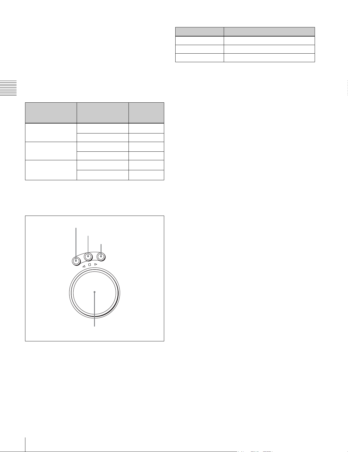
5 Search control section
1 SHUTTLE button
2 JOG button
3 VAR button
V
G
A
O
J
E
L
T
T
U
H
S
E
S
R
E
V
E
R
a SHUTTLE button
Press to enter shuttle mode. In this mode, the button lights
and playback at the speed corresponding to the angle of
rotation of the search dial is possible. The playback speed
range depends on the frame frequency of the unit. In this
mode, the search dial clicks at the positions for 0 (still
picture) and ±10 times normal playback speed (HDCAM/
Digital Betacam) or ±8 times normal playback speed
(HDCAM-SR).
R
F
O
R
W
A
R
D
4 Search dial
Frame frequency
Playback speed
23.98/24 Hz Ranging from ±50
25 Hz Ranging from ±48
29.97/30 Hz Ranging from ±40
b JOG button
Press to select jog mode. In this mode, the button lights up
and playback is possible at –1 to +1 times normal speed, ±2
times normal speed (HDCAM/HDCAM-SR), or ±3 times
normal speed (Digital Betacam) (determined by the setting
in the VTR SETUP menu item 107 “JOG DIAL
RESPONSE”). In this mode, the search dial does not click.
a)
c VAR (variable) button
Press to select variable speed playback mode for noiseless
a)
playback in the range from –1 to +2 times normal speed
(HDCAM/HDCAM-SR) or –1 to +3 times normal speed
(Digital Betacam). Playback exceeding this speed range is
a)
a)
not possible. The search dial clicks at the positions for stillpicture and normal playback speed.
d Search dial
Rotate to search for edit points. Rotate the dial clockwise
for forward playback (the B indicator lights up) or
counterclockwise for reverse playback (the b indicator
lights up). The x indicator lights up while the VTR is in
stop mode.
Shuttle mode: The playback speed corresponds to the
angle of rotation of the search dial. The playback
speed range depends on the frame frequency of the
unit. (See item 1 SHUTTLE button.) The dial clicks
at the positions for 0 (still picture) and ±10 times
normal playback speed (HDCAM/Digital Betacam)
or ±8 times normal playback speed (HDCAM-SR).
Jog mode: The playback speed corresponds to the
rotational speed of the dial (–1 to +1 times normal
speed, ±2 times normal speed (HDCAM/HDCAMSR), or ±3 times normal speed (Digital Betacam))
depending on the setting of the VTR SETUP menu
item 107 “JOG DIAL RESPONSE”). The dial does
not click.
Variable speed playback mode: Noiseless playback is
possible in the range from –1 to +2 times normal
speed (HDCAM/HDCAM-SR) or –1 to +3 times
normal speed (Digital Betacam). The speed settings
can be changed using the menu. The dial clicks at the
positions for still-picture and normal playback speed.
Capstan override mode: Rotating the dial while holding
down the PLAY button changes the playback speed
by up to ±15%.
22
2-1 Control Panel
Page 23
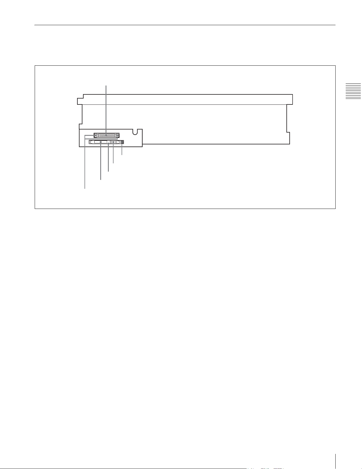
2-1-3 System Set-Up Panel
Lift the lower control panel up to its horizontal position to
access the system set-up panel.
CONTROL PANEL connector
CONTROL PANEL
Card slot eject button
Memory stick eject button
Memory stick receptacle
PCM CIA card slot
Harness restraint
For details of opening and closing the control panel, refer
to the Maintenance Manual.
Chapter 2 Locations and Functions of Parts
For details, see “3-4 Using a Memory Stick” on page 35.
2-1 Control Panel
23
Page 24
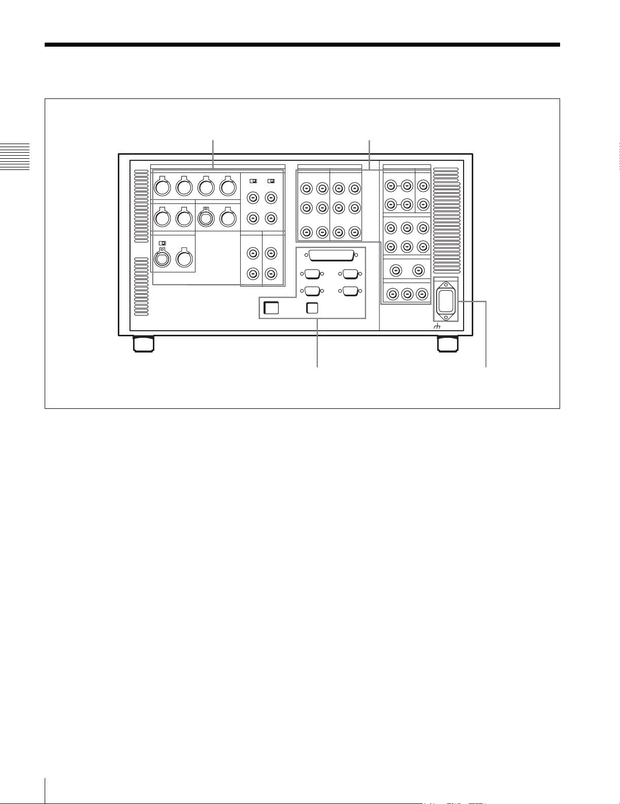
2-2 Connector Panel
1 ANALOG I/O section (see page 25)
Chapter 2 Locations and Functions of Parts
3 Remote input/output section
(see page 28)
2 DIGITAL I/O section (see page 27)
4 Power supply
(see page 28)
24
2-2 Connector Panel
Page 25
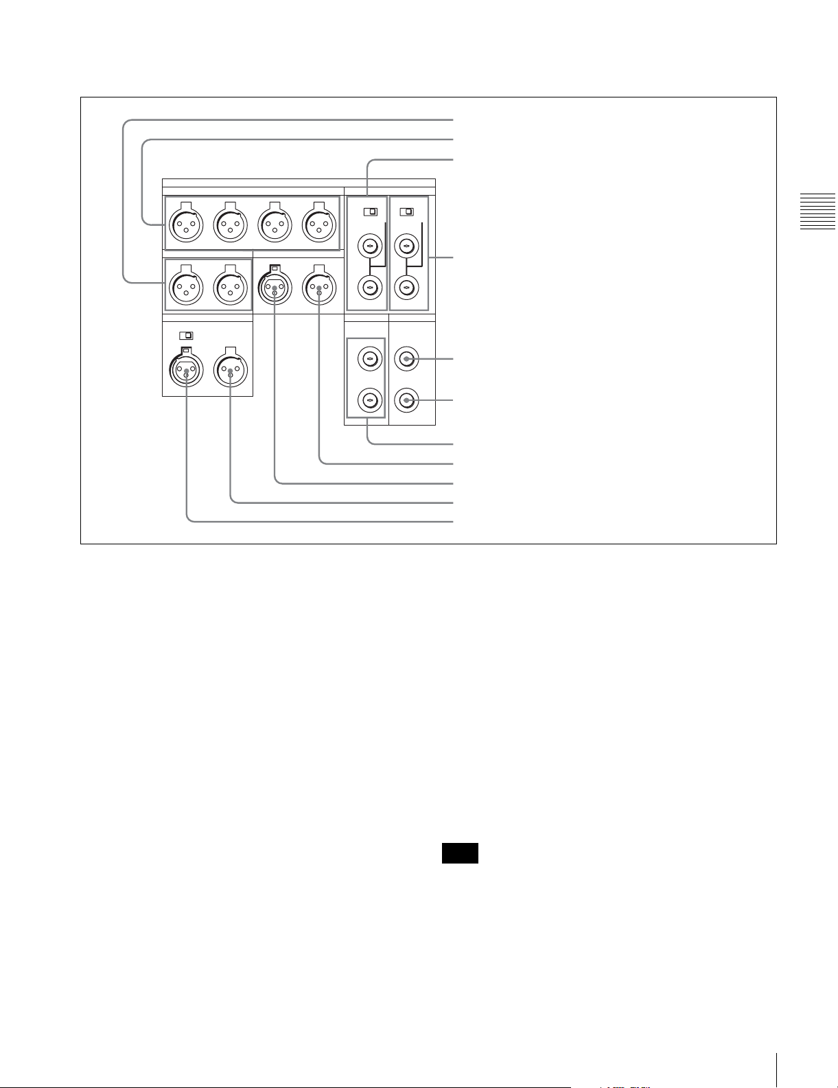
1 ANALOG I/O (input/output) section
CH1
MONITOR OUTPUT
R L IN OUT
AUDIO OUTPUT
CH2 CH3 CH4
ANALOG I/O
OFF ON
TIME CODE
REF. INPUT
2 (OPTION)
1
OFF ON
75 75
1 MONITOR OUTPUT L/R connectors
2 AUDIO OUTPUT CH1 to CH4 connectors
3 REF. INPUT 1 connectors and 75Ω termination switch
Chapter 2 Locations and Functions of Parts
4 REF. INPUT 2 connectors and 75Ω termination switch
600
OFF ON
IN
CUE
OUT
HD REF. OUT SD OUT
SYNC
1
COMPOSITE
(MONITOR)
2
a MONITOR OUTPUT L/R connectors
(XLR-3-31, male)
These output the audio signals for monitoring L and R
channels. To select the signals to output, use the
MONITOR R and MONITOR L buttons on the lower
control panel.
For details, see “5-1-2 Selecting Audio Signals” on
page 103.
b AUDIO OUTPUT CH1 to CH4 connectors
(XLR-3-31, male)
These output up to four analog audio signal lines (channels
1 to 4).
c REF. INPUT 1 connectors (BNC) and 75Ω
termination switch
Input a reference video signal of the selected field
frequency. Select HD or SD with the VTR SETUP menu
item 006 “EXTERNAL REFERENCE select”. When HD
is selected, input a tri-level SYNC signal. When SD is
selected, input a video signal with chroma burst (VBS) or
a monochrome video signal (VS).
A loop-through connection is possible. Set the 75Ω
termination switch to OFF if you are using a loop-through
connection and set it to ON if you are not using a loopthrough connection.
5 SD OUT SYNC connector
6 SD OUT COMPOSITE (MONITOR) connector
7 HD REF. OUT connectors
8 TIME CODE OUT connector
9 TIME CODE IN connector
0 CUE OUT connector
qa CUE IN connector (SRW-5500 only)
d REF. INPUT 2 connectors (BNC) and 75Ω
termination switch
Input a reference video signal of the field frequency
selected for the format converter output. Select HD or SD
with the VTR SETUP menu item A08 “FC REFERENCE
select”. When HD is selected, input a tri-level SYNC
signal for external synchronization. When SD is selected,
input a video signal with chroma burst (VBS) or a
monochrome video signal (VS). A loop-through
connection is possible. Set the 75Ω termination switch to
OFF if you are using a loop-through connection and set it
to ON if you are not using a loop-through connection.
e SD OUT SYNC connector (BNC)
This outputs an NTSC or PAL signal for external
synchronization.
Note
The output phase is the same as that of the composite
signal output from the SD OUT COMPOSITE
(MONITOR) connector.
Because the output phase changes with the operation mode
of the VTR, use this for synchronization with the video
monitor.
2-2 Connector Panel
25
Page 26

f SD OUT COMPOSITE (MONITOR) connector
(BNC)
Outputs an analog composite signal for a video monitor.
When the ALT/[F6] (CHARA SUPER) setting in the TC
menu is on, character signals such as time codes are
superimposed on the output.
g HD REF. OUT connectors (BNC)
Output an HD tri-level sync signal during tape playback.
h TIME CODE OUT connector (XLR 3-31, male)
Chapter 2 Locations and Functions of Parts
Outputs the following time codes according to the VTR
operation mode.
In playback mode: Playback time code
In recording mode: Time code generated by the internal
time code generator, or time code input to the TIME
CODE IN connector.
To select the output signal, use the VTR SETUP menu
item 613 “TC OUTPUT SIGNAL IN REGENE MODE.”
Setting Description
off tape In playback mode, playback time code signal
is output. In recording mode, TCG time code
signal is output.
regene Only when the servo is locked in playback
through The time code signal from the TIME CODE IN
mode, playback time code signal is
regenerated and output. In all other cases,
output is the same as for the “off tape” setting.
connector is output as it is. (Used for cascade
connections.)
(For more information about cascade
connections, see “3-1-3 Cascade
Connection” on page 31.)
i TIME CODE IN connector (XLR 3-32, female)
Accepts external time code for recording to tape. Connect
to the time code output connector of the external
equipment.
j CUE OUT (cue output) connector
(XLR 3-31, male)
Outputs cue track audio during HDCAM or Digital
Betacam playback.
Note
There is no cue track on an HDCAM-SR tape, and
therefore no output.
k CUE IN (cue input) connector (XLR 3-31, female)
(SRW-5500 only)
Enabled only during HDCAM format recording.
26
2-2 Connector Panel
Page 27
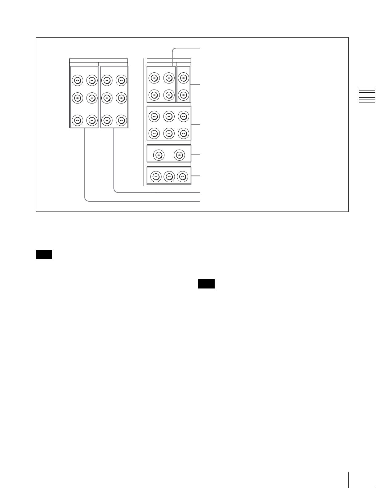
2 DIGITAL I/O (input/output) section
1 HD SDI INPUT A/B connectors
DIGITAL I/O (AES/EBU)
AUDIO
CH1/2 CH3/4 CH1/2 CH3/4
CH5/6 CH7/8 CH5/6 CH7/8
CH9/10 CH11/12 CH9/10 CH11/12
OUTPUT
AUDIO
DIGITAL I/O
HD SDI INPUT FC OUT BINPUT
INPUT
MONITOR
B INPUT
MONITOR
2 MONITOR
MONITOR
SD SDI OUT
1
2
A
B(OPTION)
HD SDI OUTPUT
1
A
B(OPTION)AB(OPTION)AB(OPTION)
FORMAT CONV. OUT (OPTION)
12
1 2 MONITOR
a HD SDI (SDI video/audio) INPUT A/B connectors
(BNC)
These accept SDI video/audio signals.
Note
The INPUT MONITOR connectors are for use with an
input monitor and does not follow the standards for output.
2 FC OUT B connectors
Chapter 2 Locations and Functions of Parts
3 HD SDI OUTPUT connectors
4 FORMAT CONV. OUT (OPTION) connectors
5 SD SDI OUT connectors
6 DIGITAL I/O (AES/EBU) OUTPUT connectors
7 DIGITAL I/O (AES/EBU) INPUT connectors
d FORMAT CONV. OUT (OPTION) connectors
(BNC)
These output two sets of format-converted video/audio
signals.
When the ALT/[F5] (PD CHARA) buttons are set to ON in
the TC menu, the output has time data or other text
superimposed on the signal.
b FC OUT B (FORMAT CONV. OUTPUT B
(OPTION)) connectors (BNC)
These are only effective when the optional HKSR-5001
format converter board is installed. When the output
format is selected as 4:4:4, LINK B is output, and when the
output format is selected as 4:2:2 it is not output.
c HD SDI (SDI video/audio) OUTPUT connectors
(BNC)
These output three sets of SDI video/audio signals.
When the ALT/[F6] (CHARA SUPER) buttons are set to
ON in the TC menu, time data or other text data is
superimposed on the signal output from the MONITOR A
connector.
Note
This is only valid when the optional HKSR-5001 format
converter board is installed. When the output format is
selected as 4:4:4, LINK A is output.
e SD SDI (1/2/monitor) OUT connectors (BNC)
These output three sets of video/audio signals. When the
ALT/[F6] (CHARA SUPER) buttons are set to ON in the
TC menu, time data or other text data is superimposed on
the output from the MONITOR OUTPUT L/R connector.
f DIGITAL I/O (AES/EBU) OUTPUT connectors
(BNC)
These output digital signals in AES/EBU format for
channels 1 to 12.
g DIGITAL I/O (AES/EBU) INPUT connectors
(BNC)
These accept digital signals in AES/EBU format for
channels 1 to 12.
2-2 Connector Panel
27
Page 28
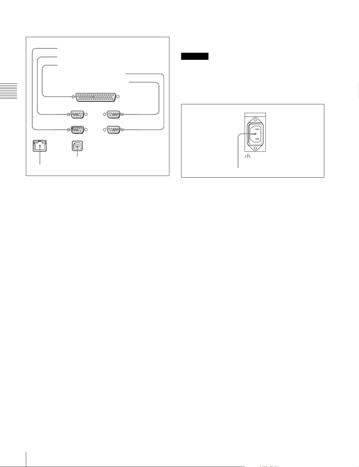
3 Remote input/output section
1 RS232C connector
2 REMOTE1-IN(9P) connector
3 REMOTE 2 PARALLEL I/O(50P) connector
4 VIDEO CONTROL connector
5 REMOTE1-I/O(9P) connector
REMOTE 2 PARALLEL I/O(50P)
Chapter 2 Locations and Functions of Parts
REMOTE 1-IN(9P) REMOTE 1-I/O(9P)
RS232C
VIDEO CONROL
g ETHERNET connector
Used for monitoring the VTR by SNMP, or for setting or
changing VTR settings by HTTP.
CAUTION
For safety, do not connect the connector for peripheral
device wiring that might have excessive voltage to this
port. Follow the instructions for this port.
4 Power supply
AC IN
ETHERNET
7 ETHERNET connector
USB
6 USB connector
a RS232C connector (RS-232C serial interface)
(D-sub 9-pin)
This is used for manufacturing and services.
b REMOTE 1-IN(9P) connector (D-sub 9-pin,
female)
Use this, with the supplied 9-pin remote control cable, to
connect the unit to another SRW-5000/5500 unit or
another HD VTR unit to carry out editing with a BVEseries editor BVE-900/910/2000/9000/9100.
c REMOTE 2 PARALLEL I/O(50P) connector (D-
sub 50-pin, female)
Inputs an external remote control signal.
For details, refer to the Maintenance Manual Volume 1.
d VIDEO CONTROL (Digital Video Processor
Control) connector (D-sub 9-pin, female)
Connects to the optional HKDV-900 HD Digital Video
Controller to enable remote control of the internal digital
video processor. Turn off the power before connecting the
remote controller.
-AC IN connector
-AC IN connector
Connects to an AC outlet using an appropriate power cord.
e REMOTE 1-I/O(9P) connector (D-sub 9-pin,
female)
Use this, with the supplied 9-pin remote control cable, to
connect the unit to another SRW-5000/5500 unit or
another HD VTR unit to carry out editing with a BVEseries editor BVE-900/910/2000/9000/9100.
f USB connector
This is used for manufacturing and services.
28
2-2 Connector Panel
Page 29
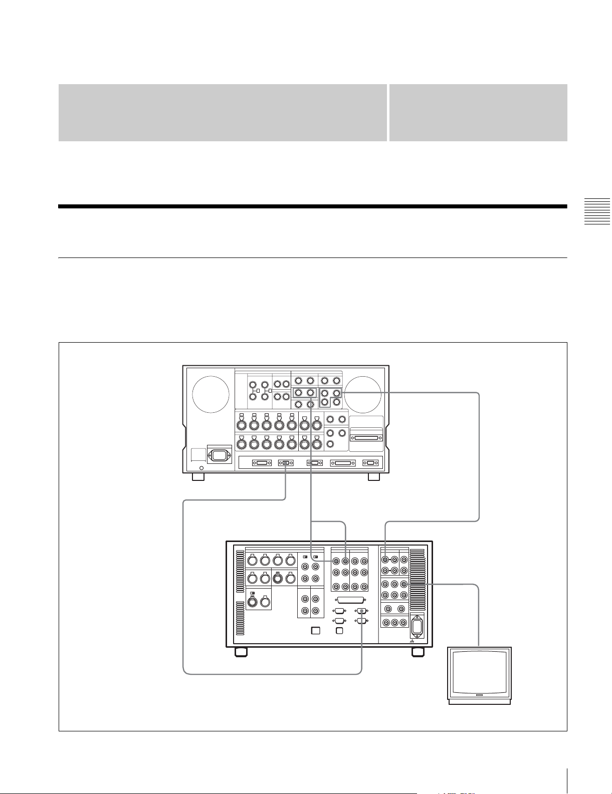
Setting Up the VTR
Chapter
3
3-1 Connecting External Equipment
3-1-1 Making HD Digital Connections
This example shows the connections when using an HDWF500 as player and an SRW-5000/5500 as recorder, in
59.94i or 60i mode.
HDW-F500 (Player)
REMOTE (9P)
9-pin remote control cable
See “Specifications” in the Appendix (page 131) for
recommended XLR/BNC and P/S converters.
AUDIO
OUTPUT
Chapter 3 Setting Up the VTR
HD SDI OUTPUT
a) The figure shows the SRW-5500.
DIGITAL I/O INPUT
SRW-5000/5500 (Recorder)
REMOTE 1-I/O(9P)
HD SDI INPUT
HD SDI OUTPUT
a)
Video monitor
(HD serial monitor)
3-1 Connecting External Equipment
29
Page 30
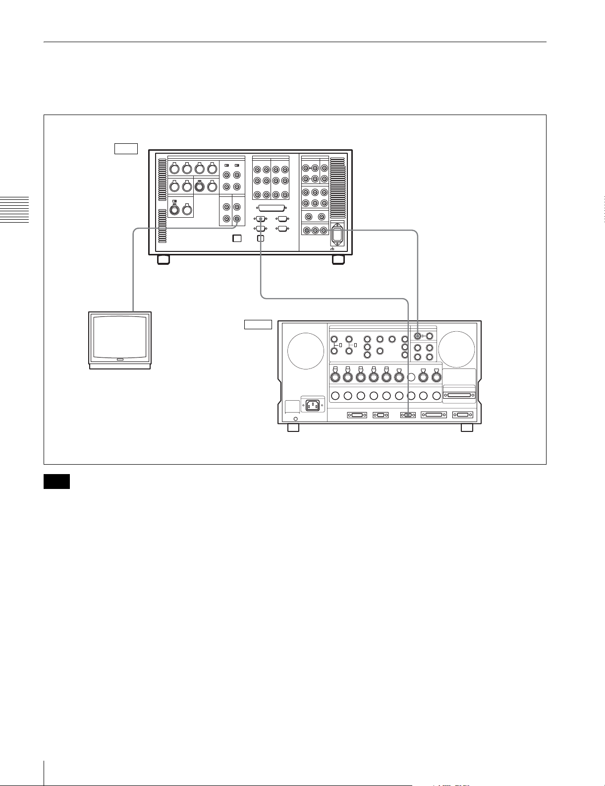
3-1-2 Making NTSC/PAL Digital Connections
This example shows how to connect two VTRs, an SRW5000/5500 as the player and a DVW-500 D-1 Component
Digital VTR as the recorder.
Input
SRW-5000/5500 (Player)
Chapter 3 Setting Up the VTR
SD OUT
COMPOSITE (MONITOR)
BNC cable
Video monitor
(NTSC/PAL monitor)
a)
REMOTE 1-IN(9P)
9-pin remote control cable
Output
SD SDI OUT
REMOTE 1-OUT
BNC cable
DIGITAL I/O SERIAL V/A INPUT
a) The figure shows the SRW-5500.
Note
For color frame editing using the SRW-5000/5500 as the
player and an NTSC/PAL digital device as the recorder, set
the VTR SETUP menu item 005 “SERVO/AV
REFERENCE select” to “external” and set the menu item
006 “EXTERNAL REFERENCE select” to “extern SD”.
DVW-500 (Recorder)
30
3-1 Connecting External Equipment
Page 31

3-1-3 Cascade Connection
This example shows how to connect multiple SRW-5000/
5500 VTRs together for simultaneous recording.
HDW-F500 (Player)
TIME CODE OUT
TIME CODE IN
Note
On the recording VTRs, set the VTR SETUP menu item
613 “TC OUTPUT SIGNAL IN REGENE MODE” to
“through”.
HD SDI OUTPUT
HD SDI INPUT
BNC cable
Chapter 3 Setting Up the VTR
SRW-5000/5500 (Recorder)
TIME CODE OUT
a)
Digital video distributor
HKPF-103M
HD SDI
OUTPUT
Video monitor
(HD serial monitor)
HD SDI INPUTTIME CODE IN
SRW-5000/5500 (Recorder)
a) The figure shows the SRW-5500.
a)
3-1 Connecting External Equipment
31
Page 32

3-2 Reference Signals
This section describes how reference signals for the video
output are selected.
3-2-1 Reference Signals for Output Video
Depending on the operating condition, VTR SETUP menu
settings, the input signal, and the video output signal from
the VTR can be synchronized as follows.
Start
Chapter 3 Setting Up the VTR
ext.
What is the setting of
the VTR SETUP menu
item 005 “SERVO/AV
REFERENCE select”?
auto
Is the VTR currently
recording or is EDIT
PRESENT on?
No
What is the setting
of the VTR SETUP
menu item 006
“EXTERNAL
REFERENCE
select”?
input
Yes
extrn SD
a) The signal on the REF. INPUT 2 connector is the signal for FORMAT CONV.
output. Use the “A08: FC REFERENCE select” menu item to switch between
HD and SD for the signal input to the REF. INPUT 2 connector.
32
3-2 Reference Signals
extrn HD
Is there a signal of the
correct frequency on
the REF. INPUT 1 or
a)
connector?
2
No
Synchronization
with the reference
video signal input to
the REF. INPUT 1
a)
or 2
Yes
connector
No external synchronization (synchronization is internal)
Is there a signal of the
correct frequency on
the REF. INPUT 1 or
a)
connector?
2
No
Synchronization
with the video signal
input to the REF.
INPUT 1 or 2
connector
Yes
a)
Is there an input
signal on the HD SDI
INPUT connector?
No
Synchronization
with the video signal
input to the HD SDI
INPUT connector
Yes
Page 33

3-2-2 Reference Signal Connections
For playback
Make the reference signal connections as follows,
according to your recording or playback requirements.
Reference signal connections
For recording signals from a switcher or signal
generator
Reference signal
Switcher or signal generator
HD SDI INPUTREF. INPUT 1
SRW-5000/5500
75Ω termination switch: ON
a) The figure shows the SRW-5500.
For recording signals from a HD VTR
a)
Reference signal
REF. INPUT 1
75Ω termination switch: ON
a) The figure shows the SRW-5500.
Note
SRW-5000/5500
HD SDI OUTPUT
HD serial input
monitor
a)
The following signals can be used as a reference signal.
• HD trilevel SYNC signal of an appropriate field
frequency for external synchronization
• Black burst signal of 525/59.94 Hz
• Black burst signal of 625/50 Hz
Input the signal of the appropriate field frequency for your
system.
Chapter 3 Setting Up the VTR
Reference signal
75Ω termination switch: OFF
REF. INPUT 1
75Ω termination switch: ON
a) The figure shows the SRW-5500.
SRW-5000/5500 (Recorder)
HD SDI INPUT AREF. INPUT 1
HD SDI OUTPUTHD SDI INPUT
HDW-F500 (Player)
Sync signals in 720p mode
Synchronize to an external sync signal when you want to
record or play back 720p signals on this unit (including
a)
editing).
• When the 720/59.94p system is selected:
You can select the following reference signals from
menu item 006 “EXTERNAL REFERENCE select”.
extrn HD: 1080/59.94i tri-level SYNC signal
extrn SD: 525 black burst signal
• When the 720/50p system is selected:
You can select the following reference signals from
menu item 006 “EXTERNAL REFERENCE select”.
extrn HD: 1080/50i tri-level SYNC signal
extrn SD: 625 black burst signal
When you have directly connected the input and output
connectors of two SRW-5000/5500 units, you can also
perform dubbing with the VTR SETUP menu item 005
being set to “input”.
3-2 Reference Signals
33
Page 34

3-3 Handling Cassettes
3-3-1 Recommended Cassettes
3-3-2 Inserting and Ejecting Cassettes
Always turn on the VTR before inserting or ejecting
cassettes.
For recording and playback:
1
Use
/2 inch HDCAM-SR cassettes.
The maximum recording time is as shown in the following
table.
System
frequency
HDCAM
SR-cassette
Chapter 3 Setting Up the VTR
S-size cassette 40 minutes 48 minutes 50 minutes
L-size cassette 124 minutes 149 minutes 155 minutes
For playback only:
1
Use
/2 inch HDCAM or Digital Betacam cassettes.
The maximum playback time is as shown in the following
table.
System
frequency
HDCAM
cassette
S-size cassette 40 minutes 48 minutes 50 minutes
L-size cassette 124 minutes 149 minutes 155 minutes
Note
HDCAM cassettes are for playback only on the
SRW-5000. They can be played back and recorded on the
SRW-5500.
29.97/30 Hz 25 Hz 23.98/24 Hz
29.97/30 Hz 25 Hz 23.98/24 Hz
Inserting a cassette
1
2
S-size cassette
L-size cassette
1
Turn the POWER switch to ON.
2
Before inserting a cassette, check the following points:
• There is no slack in the tape.
• An error message does not appear in the menu
display.
• The window of the cassette is facing up.
If there is any slack in the tape, see “Removing slack
in the tape” on page 34.
When inserting an S-size cassette, make sure it is
aligned with the marks on the cassette insertion slot.
System
Digital
frequency
Betacam cassette
S-size cassette 40 minutes 40 minutes
L-size cassette 124 minutes 124 minutes
Note
Playing back a digital Betacam cassette requires the
Digital Betacam Option (HKSR-5002).
Storage of cassettes
Store your cassettes at room temperature and normal
humidity.
29.97 Hz 25 Hz
The cassette is loaded automatically, and the tape is
wound around the drum.
Removing slack in the tape
Press one of the reels in slightly, then carefully rotate it in
the direction of the arrow until it stops.
34
3-3 Handling Cassettes
Page 35

Preventing double cassette inserting
When a cassette is loaded, an orange lock-out bar appears
in the cassette insertion slot to prevent users from
attempting to load another cassette.
Ejecting the cassette
Press the EJECT button.
The tape is unthreaded and the cassette is automatically
ejected. This operation takes a few seconds.
To cancel ejecting a cassette
Press any operation button before the cassette is
completely ejected. The cassette is loaded again and the
operation corresponding to the button you pressed starts.
3-4 Using a Memory Stick
When a Memory Stick is inserted in the VTR, the file data
can be stored on the Memory Stick, which enables you to
share data among VTRs.
Inserting a Memory Stick
Insert a Memory Stick with the label side up into the
Memory Stick slot until it clicks and the access lamp
lights in red.
Chapter 3 Setting Up the VTR
3-3-3 Preventing Accidental Erasure
To prevent accidental erasure of material recorded on a
tape, push in the record-protect plug.
L-size cassette
S-size cassette
Push in the record-protect plug. (ON)
To restore the tape for recording, return the plug to its
original position. (OFF)
When a cassette with this plug pushed in is inserted into
the VTR, the REC INHIBIT indicator on the lower control
panel lights up and recording will not start, even if you
press the REC/EDIT button.
To restore the tape for recording, return the plug to its
original position.
Eject button
Memory Stick
Label side up
Note
Never insert/remove a Memory Stick during access to
data.
To remove a Memory Stick
Push the eject button on the Memory Stick PC card
adaptor, and pull the Memory Stick out.
3-4-1 Notes on Memory Stick
On Memory Stick
Memory Stick is a new compact, portable and versatile IC
recording medium with a data capacity that exceeds that of
a floppy disk. Memory Stick is specially designed for
exchanging and sharing digital data among Memory Stick
compatible products. Because it is removable, Memory
Stick can also be used for external data storage.
Types of Memory Stick
There are two types of Memory Stick: MagicGate
Memory Stick that is equipped with the MagicGate
copyright protection technology and general Memory
Stick. Use the general type of Memory Stick (8MB,
16MB, 32MB, 64MB, 128MB) with this unit.
3-4 Using a Memory Stick
35
Page 36

On MagicGate
MagicGate is copyright-protection technology that uses
encryption technology.
turn off the power of the unit or remove the Memory
Stick. This may damage the data.
Before using a Memory Stick
Terminal
Write-protect
tab
Chapter 3 Setting Up the VTR
Labeling position
• You cannot record or erase data when the write-protect
tab on the Memory Stick is set to LOCK.
• We recommend backing up important data.
• Image data may be damaged in the following cases:
- If you remove the Memory Stick, or turn the power
off when the access lamp is lit or flashing
- If you use a Memory Stick near static electricity or a
magnetic field
Memory Stick and are the trademarks of Sony
Corporation.
MagicGate Memory Stick and are the trademarks of
Sony Corporation.
Notes
• Prevent metallic objects or your finger from coming into
contact with the terminal of the connecting section.
• Do not attach any material other than the supplied label
to the label space.
• Attach the label at the prescribed labeling position.
Make sure the label is attached at the labeling position
properly.
• Do not bend, drop, or apply strong shock to a Memory
Stick.
• Do not disassemble or modify a Memory Stick.
• Do not let the Memory Stick get wet.
• Do not use or keep a Memory Stick in locations that are:
- Extremely hot such as in a car parked in the sun
- Under direct sunlight
- Very humid or subject to corrosive gases
• When you carry or store a Memory Stick, keep it in its
case.
• The PCMCIA memory card supplied with the HDW-
500/F500 and the HDW-2000 series cannot be used with
the SRW-5000/5500.
During access to data
While data are being read from or written to the Memory
Stick, do not shake this unit or subject it to shock. Do not
36
3-4 Using a Memory Stick
Page 37

Menu Settings
Chapter
4
4-1 Registering and Storing Menu Settings
The operating conditions of the VTR are set using the
menu operation section on the lower control panel.
Menu items are divided among eight different menus
(HOME, TC, VIDEO, AUDIO, CUE, PF1, PF2, SET UP).
You can register any frequently used items to the HOME,
TC, VIDEO, AUDIO, PF1, and PF2 menu screens. By
registering the necessary items in advance, setting
operations are made quicker. The contents of the eight
VTR memory banks can, in turn, be stored on a memory
stick for later recall.
4-1-1 Menu Configuration
This VTR has two kinds of menus.
VTR SETUP menu list
This menu contains items that specify the initial operating
conditions of the VTR. You can change these settings
directly without registering the items to the function
buttons.
Press the [F6] (VTR SETUP) button in the SET UP menu
to display this menu.
For details on setting operating conditions of the VTR, see
“4-7-1 VTR SETUP Menu” on page 98.
PF ASSIGN menu list
This is a list of menu items which can be registered to the
HOME, TC, VIDEO, AUDIO, PF1 and PF2 menu screens
as well as the screen that is displayed by pressing the ALT
button (the ALT screen). This includes all VTR SETUP
menu item.
Press the [F4] (PF ASSIGN) button in the SET UP menu to
display this menu.
HOME menu
TC menu
VIDEO menu
AUDIO menu
CUE menu
PF1 menu
PF2 menu
SETUP menu
[F4] (PF ASSIGN) button
[F6] (VTR SETUP) button
PF button assignment allows you to assign the same item
also to a different menu screen or button.
Registration
PF button 1&2
ASSIGN menu
VTR SETUP
menu list
4-1-2 Changing Menu Settings
To activate the HOME, TC, VIDEO, AUDIO, CUE, PF1,
PF2, or SET UP menu, press the respective menu button.
Menu items are assigned to function buttons ([F1] to [F10])
in each menu. When two items are registered to the same
function button, you can display the second item by
pressing the ALT button.
The example below describes the procedure for changing
the setting specified by the ALT/[F6] (CHARA SUPER)
button in the TC menu.
Chapter 4 Menu Settings
For details on registering items, see “4-1-3 Registering
Items to the VTR SETUP Menu” on page 38.
The menu configuration of the VTR is shown in the
following figure.
4-1 Registering and Storing Menu Settings
37
Page 38

1
2 3
1
Press the TC button.
The first page of the TC menu appears in the display.
4-1-3 Registering Items to the VTR SETUP Menu
You can register 120 menu items including those displayed
by pressing the ALT button in the HOME, TC, VIDEO,
AUDIO, PF1, and PF2 menus. By registering frequently
used menu items, the settings can be carried out together.
Registering items
3
TIMER
Chapter 4 Menu Settings
2
Press the ALT button.
SEL
LTC
TC
TGA
TIMER
RESET
AIN --:--:--:-- AOUT --:--:--:--
TIMER
IN --:--:--:-- OUT --:--:--:--
SET
TIMER
HOLD
TCR
REGENE
SEL
SOURCE
LTC
int-L
The second page of the TC menu appears in the
display.
PLAY LOCK
INTRP DF
F2
00H02M39S18
TCG
RUN
MODE
free
DF/NDFDFTC2
MODE
prst
SEL
OFF
F
4,5
2
1
Press the SET UP button.
6 8
1
The SET UP menu appears in the display.
2
Press the [F4] (PF ASSIGN) button.
The PF ASSIGN menu appears in the display.
3
Press the [F1] (PAGE) button to select the menu where
you wish to register an item.
The selected menu appears and the items currently
TAPE
TIMER
LTC
24H
TCA
POPSET
MENU
AIN --:--:--:-- AOUT --:--:--:--
TCCONY
IN --:--:--:-- OUT --:--:--:--
MENU
-
PDTC
DIEP
off
PD
CHARA
CHARA
SUPER
off
ON
PLAY LOCK
INTRP DF F2
00H02M39S18
CHARA
M-POS
1
CHARA
V-POS
22
F
registered to the menu appear in the middle of the
display.
If the function button assignments are other than the
default, the [F3] (PAGE DEF.) button is valid.
To return all function buttons to the default
settings
Press the [F3] (PAGE DEF.) button.
4
Press the cursor R or r button to move the cursor (B) to
the function button where the item is to be registered.
To return to the first page
Press the ALT button again.
3
Press the [F6] (CHARA SUPER) button to change the
The selected function button is highlighted and the
current setting is displayed.
setting.
Each time the button is pressed, the setting changes.
38
4-1 Registering and Storing Menu Settings
Page 39

F1
PAGE
PAGE
DEF.
KEY
DEF.
PAE
READ
off
PASTE CANCEL SAVE/
BLANK
Current setting
Function button
where item is to
be registered
To unregister the selected item
Press the [F6] (BLANK) button.
ALT+HOME
F1 : 001
F2 :
F3 : K17
F4 :
F5 :
F6 : 302
F7 : K18
F8 : K25
F9 : K44
-
VTR SETUP MENU
001:PRE READ
002:REC INH
003:REC INH ARE
005:SERVO REF
006:EXT REF SEL
007:SYNC PLAY
008:LOCAL ENA
009:LOCAL NAP
017:PB/EE STATE
EXIT
4-1-4 VTR Memory Bank Function
Eight VTR memory banks are provided for storing up to
eight sets of menu settings.
The contents of all eight VTR memory banks can be stored
on a memory stick.
Current menu settings in the
VTR (CURRENT SETUP).
These settings are stored
outside the VTR memory
banks even when the power
is off.
Storing/recalling
When a function button with other than the default
assignment is selected, the [F4] (KEY DEF.) button is
valid.
To return the selected function button to its default
setting, press the [F4] (KEY DEF.) button.
5
Press the cursor t button to move the cursor (B) to
the menu list (PF ASSIGN menu), then press the
cursor R or r button to move the cursor to the menu
item to be registered.
To scroll the menu faster
Press the cursor R or r button while holding down the
SFT button.
ALT+HOME
PAGE
PAGE
DEF.
KEY
DEF.
F7
DMC
F1 : 001
F2 :
F3 : K17
F4 :
F5 :
F6 : 302
F7 : K18
F8 : K25
F9 : K44
PASTE CANCEL SAVE/
BLANK
VTR SETUP MENU -
632:JUMP TC sel
705:YAOO
706:MASTER(HD)
708:Y LEVEL(HD)
710:PB LVL(HD)
711:PR LVL(HD)
712:SETUP(HD)
713:SYNC(HD)
714:FINE(HD)
-
EXIT
Item to be
registered
VTR memory banks (SETUP
BANK1 to 8 and F). SETUP
Storing/recalling
BANK F contains the factoryset menu settings. By calling up
SETUP BANK F, you can
restore all menu items to their
factory settings.
Memory stick (SETUP BANK
Storing/recalling
0 to 8). The stick stores
setting data in same way as
the VTR memory banks.
These contents can be later
called up in the VTR.
For details on memory stick use, see see “4-1-5 Memory
Stick Operations” on page 41.
For details on adding titles to the contents of the VTR
memory bank, see “4-1-6 Adding Titles to the Data” on
page 46.
Note
Chapter 4 Menu Settings
6
Press the [F7] (PASTE) button to register the item.
The new item is registered to the function button.
7
Repeat steps 3 to 6 to register more items.
To cancel the registration of all new items
Press the [F9] (CANCEL) button.
8
Press the [F10] (SAVE/EXIT) button to save the newly
registered items.
The registration is completed and the SET UP menu
appears in the display again.
The contents of SETUP BANK
F cannot be changed.
Storing the current VTR menu settings to a
VTR memory bank
32
4 6
4-1 Registering and Storing Menu Settings
1
CLR button
5
39
Page 40

1
Press the SET UP button.
The SET UP menu appears in the display.
2
Press the [F1] (VTR BANK) button.
The VTR BANK menu appears in the display.
DIREC-
TION
VTR BANK
SETUP BANK 1
1 (Preset)
2 (Preset)
3 (Preset)
4 (Preset)
5 (Preset)
6 (Preset)
7 (Preset)
8 (Preset)
1F (Preset)
COPY EXITEDIT
UNDO
VTR BANK
CURRENT SETUP
AAA C
TITLE
VTR BANK
CURRENT SETUP TITLE EDIT
CURRENT SETUP
(Preset)
(Preset)_
A BCDEFGHIJKLMNOPQRSTUVWXYZ
abcdefghjiklmnopqrstuvwxyz
0123456789[]()<>@+-*=!?:;
$#%&,."\^_'/~ {} HD1D2CAM
SPACE SET
BACK
LETTER
SPACE
For more information, see “4-1-6 Adding Titles to the
Data” on page 46.
Recovering previous settings after new settings
have been saved
VTR BANK
SETUP BANK 1
1 (Preset)
2 (Preset)
3 (Preset)
4 (Preset)
5 (Preset)
6 (Preset)
'
7 (Preset)
8 (Untitled)
1F (Preset)
CANCEL SAVE/
EXIT
Press the [F2] (UNDO) button to recover the previous
settings.
Chapter 4 Menu Settings
3
Press the [F8] (DIRECTION) button to select the <
direction.
Preventing accidental erasure after saving settings
Move the cursor to the memory bank to be protected
and press ALT/[F2] (PROTECT) buttons. A will
4
Press the cursor T button to move the cursor (B) to
appear next to the selected bank.
CURRENT SETUP[C], then press the [F6] (EDIT
TITLE) button to add a title to the current menu
8
Press the [F10] (EXIT) button.
settings of the VTR.
The SET UP menu appears again.
For details, see “4-1-6 Adding Titles to the Data” on
page 46.
5
Press the cursor t button to move the cursor (B) to
Recalling menu settings from a VTR
memory bank
SETUP BANK, then press the cursor R or r button to
move the flashing cursor bar to the number of the VTR
memory bank to be used for saving the current menu
settings.
The flashing cursor bar indicates the storage
destination.
6
Press the [F9] (COPY) button.
A message appears in the display asking you to
confirm the operation.
To cancel the storage operation
Press the CLR button.
7
Press the [F9] (COPY) button while holding down the
SFT button.
The current menu settings are stored to the VTR
memory bank.
To add or change a title for VTR settings after
storing them to the VTR memory bank
Move the cursor (B) to the number of the VTR
memory bank where the settings are stored, then press
the [F6] (EDIT TITLE) button.
3 7
1
Press the SET UP button.
1524
The SET UP menu appears in the display.
2
Press the [F1] (VTR BANK) button.
The VTR BANK menu appears in the display.
40
4-1 Registering and Storing Menu Settings
Page 41

UNDO
VTR BANK
CURRENT SETUP
(Preset) C
TITLE
DIREC-
TION
VTR BANK
SETUP BANK 2
1 (Preset)
2 (Preset)
3 (Preset)
4 (Preset)
5 (Preset)
6 (Preset)
7 (Preset)
8 (Untitled)
F (Preset)
COPY EXITEDIT
Memory stick insertion slot
3
Press the [F8] (DIRECTION) button to select the <
direction.
The left cursor bar flashes.
4
Press the cursor R or r button to move the cursor (B) to
the number of the VTR memory bank to be recalled.
5
Press the [F9] (COPY) button.
A message asking you to confirm the operation
appears in the display.
To cancel the recalling operation
Press the CLR button.
6
Press the [F9] (COPY) button while holding down the
SFT button.
The menu settings are recalled from the selected VTR
memory bank.
When the recalling process has been completed, the
title of the VTR bank appears under CURRENT
SETUP in the display.
To eject the memory stick
Raise up the lower control panel, and press the button on
the right side of the insertion slot.
For details of opening and closing the control panel, refer
to the Maintenance Manual.
Notes
• When inserting a memory stick, press it firmly in as far
as it will go. The stick recognition status is shown on the
MEMCARD menu screen. If not inserted properly,
reinsert it.
• While data is being read from or written to the memory
stick, the status appears on the screen. During these
operations, do not remove the memory stick.
Formatting a memory stick
Memory sticks must be formatted before you can use them.
3
4,5,6
Chapter 4 Menu Settings
VTR BANK
CURRENT SETUP TITLE EDIT
CURRENT SETUP
(Preset)
SPACE CANCEL SAVE/
SPACE
7
Press the [F10] (SAVE/EXIT) button.
(Preset)_
ABCDEFGHIJKLMNOPQRSTUVWXYZ
abcdefghjiklmnopqrstuvwxyz
0123456789[]()<>@+-*=!?:;
$#%&,."\^_'/~ {} HD1D2CAM
BACK
VTR BANK
SETUP BANK 1
1 (Preset)
2 (Preset)
3 (Preset)
4 (Preset)
5 (Preset)
6 (Preset)
'
7 (Preset)
8 (Untitled)
F (Preset)
EXIT
The SET UP menu appears again.
4-1-5 Memory Stick Operations
You can store menu settings in the VTR memory banks
and cue point data to a memory stick for recall later.
12
1
Insert the memory stick.
2
Press the SET UP button.
The SET UP menu appears in the display.
3
Press the [F2] (MEMORY CARD) button.
The MEMCARD menu appears in the display.
4-1 Registering and Storing Menu Settings
41
Page 42

FORMAT
SETUP
CUESET
4
Press the [F1] (FORMAT CARD) button.
CARD
UNDO
SHOW
SHOW
CARD BANK 0
(BASEBALL) 0
(Preset) 1
(Preset) 2
(Preset) 3
(Preset) 4
(Preset) 5
(Preset) 6
(Preset) 7
(Preset) 8
SELECT
ALL
TITLE
DIREC-
TION
CURRENT SETUP
C FOOTBALL
1 (Preset)
2 (Preset)
3 (Preset)
4 (Preset)
5 (Preset)
6 (Preset)
7 (Preset)
8 (Preset)
F (Preset)
COPY EXITEDIT
A message asking you to confirm the operation
appears in the display.
FORMAT
SETUP
CUESET
3
Press the [F8] (DIRECTION) button to select the <
CARD
UNDO
SHOW
SHOW
CARD BANK 0
(BASEBALL) 0
(Preset) 1
(Preset) 2
(Preset) 3
(Preset) 4
(Preset) 5
(Preset) 6
(Preset) 7
(Preset) 8
SELECT
ALL
TITLE
DIREC-
TION
CURRENT SETUP
C FOOTBALL
1 (Preset)
2 (Preset)
3 (Preset)
4 (Preset)
5 (Preset)
6 (Preset)
7 (Preset)
8 (Preset)
F (Preset)
COPY EXITEDIT
direction.
The left cursor bar flashes.
To cancel formatting
Press the CLR button while the confirmation message
appears in the display.
Chapter 4 Menu Settings
5
Press the [F1] (FORMAT CARD) button while
holding down the SFT button.
The VTR starts formatting the memory stick.
Storing the contents of the VTR memory
banks to a memory stick
7,82
1
36 9
4,5
4
Move the cursor B to the VTR side using the cursor t
button and use the cursor R or r button to move the
cursor bar to the memory bank where the data is to be
saved.
FORMAT
SETUP
CUESET
CARD
UNDO
SHOW
SHOW
CARD BANK 0
(BASEBALL) 0
(Preset) 1
(Preset) 2
(Preset) 3
(Preset) 4
(Preset) 5
(Preset) 6
(Preset) 7
(Preset) 8
SELECT
ALL
TITLE
DIREC-
TION
CURRENT SETUP
C FOOTBALL
1 (Preset)
2 (Preset)
3 (Preset)
4 (Preset)
5 (Preset)
6 (Preset)
7 (Preset)
8 (Preset)
F (Preset)
COPY EXITEDIT
Saved data
To store the current VTR menu settings
Move the cursor (B) to the [C] (CURRENT SETUP)
position.
To store all VTR memory banks
Press the [F7] (SELECT ALL) button.
Note
If there are protected items at the destination end, it is
not possible to select the [F7] (SELECT ALL) button.
1
Press the SET UP button.
The SET UP menu appears in the display.
2
Press the [F2] (MEMORY CARD) button.
The MEMCARD menu appears in the display.
42
4-1 Registering and Storing Menu Settings
5
Move the cursor (B) to the memory stick side using the
cursor T button, and use the cursor R or r button to
move the cursor to the bank number (memory stick
side) where the data is to be saved.
Destination
FORMAT
(flashing)
CUESET
CARD
UNDO
SHOW
SETUP
SHOW
CARD BANK 0
(BASEBALL) 0
(Preset) 1
(Preset) 2
(Preset) 3
(Preset) 4
(Preset) 5
(Preset) 6
(Preset) 7
(Preset) 8
SELECT
ALL
TITLE
DIREC-
TION
CURRENT SETUP
C FOOTBALL
1 (Preset)
2 (Preset)
3 (Preset)
4 (Preset)
5 (Preset)
6 (Preset)
7 (Preset)
8 (Preset)
F (Preset)
COPY EXITEDIT
Page 43

The flashing cursor bar indicates the storage
destination.
6
To change the title of the bank, press the [F6] (EDIT
TITLE) button.
For details, see “4-1-6 Adding Titles to the Data” on
page 46.
7
Press the [F9] (COPY) button.
A message asking you to confirm the operation
appears in the display.
8
Press the [F9] (COPY) button while holding down the
SFT button.
Storage begins.
After the storage is complete, the title of the VTR
memory bank appears on the memory stick side.
1
Press the SET UP button.
The SET UP menu appears in the display.
2
Press the [F2] (MEMORY CARD) button.
The MEMORY CARD menu appears in the display.
FORMAT
SETUP
CUESET
3
Press the [F4] (SHOW CUESET) button.
CARD
UNDO
SHOW
SHOW
CARD BANK 0
(BASEBALL) 0
(Preset) 1
(Preset) 2
(Preset) 3
(Preset) 4
(Preset) 5
(Preset) 6
(Preset) 7
(Preset) 8
SELECT
ALL
TITLE
DIREC-
TION
CURRENT SETUP
C FOOTBALL
1 (Preset)
2 (Preset)
3 (Preset)
4 (Preset)
5 (Preset)
6 (Preset)
7 (Preset)
8 (Preset)
F (Preset)
COPY EXITEDIT
The display for storing cue point lists appears.
Chapter 4 Menu Settings
FORMAT
SETUP
CUESET
CARD
UNDO
SHOW
SHOW
CARD BANK 0
FOOTBALL 0
(Preset) 1
(Preset) 2
(Preset) 3
(Preset) 4
(Preset) 5
(Preset) 6
(Preset) 7
(Preset) 8
SELECT
ALL
TITLE
DIREC-
TION
CURRENT SETUP
C FOOTBALL
1 (Preset)
2 (Preset)
3 (Preset)
4 (Preset)
5 (Preset)
6 (Preset)
7 (Preset)
8 (Preset)
F (Preset)
COPY EXITEDIT
Preventing accidental erasure after saving settings
Press ALT/[F2] (PROTECT) buttons and a symbol
will appear to the right of the memory card bank
number.
9
Press the [F10] (EXIT) button.
The SET UP menu appears again.
Storing cue point lists to a memory stick
You can store up to 8 pages of cue point lists to a memory
stick along with titles.
FORMAT
SETUP
CUESET
CARD
UNDO
SHOW
SHOW
CUE POINT SET 1
MUSIC 1
(Blank) 2
(Blank) 3
(Blank) 4
(Blank) 5
(Blank) 6
(Blank) 7
(Blank) 8
SELECT
ALL
TITLE
DIREC-
TION
CURRENT CUE SET
C MOVIE
F (Blank)
COPY EXITEDIT
To return to the MEMORY CARD menu
Press the [F3] (SHOW SETUP) button.
4
Press the [F8] (DIRECTION) button to select the <
direction.
The left cursor bar flashes.
5
Use the cursor T button to move the cursor (B) to
CUE POINT SET side, then press the cursor R or r
button to move the cursor bar to the number of the
memory bank in the memory stick where you want to
store the cue point list.
6,72
48 9,10
135
Destination
FORMAT
(flashing)
SETUP
CUESET
6
Press the [F9] (COPY) button.
CARD
UNDO
SHOW
SHOW
CUE POINT SET 1
MUSIC 1
(Blank) 2
(Blank) 3
(Blank) 4
(Blank) 5
(Blank) 6
(Blank) 7
(Blank) 8
TITLE
4-1 Registering and Storing Menu Settings
SELECT
ALL
DIREC-
TION
CURRENT CUE SET
C MOVIE
F (Blank)
COPY EXITEDIT
43
Page 44

A message asking you to confirm the operation
appears in the display.
7
Press the [F9] (COPY) button while holding down the
SFT button.
The VTR stores the cue point list to the memory stick.
8
Press the [F6] (EDIT TITLE) button to add a title to the
cue point list.
FORMAT
CARD
UNDO
SHOW
SETUP
SHOW
CUESET
CARD BANK 0
(BASEBALL) 0
(Preset) 1
(Preset) 2
(Preset) 3
(Preset) 4
(Preset) 5
(Preset) 6
(Preset) 7
(Preset) 8
SELECT
ALL
TITLE
DIREC-
TION
CURRENT SETUP
C FOOTBALL
1 (Preset)
2 (Preset)
3 (Preset)
4 (Preset)
5 (Preset)
6 (Preset)
7 (Preset)
8 (Preset)
F (Preset)
COPY EXITEDIT
For details, see “4-1-6 Adding Titles to the Data” on
page 46.
3
Press the [F8] (DIRECTION) button to select the ,
Preventing accidental erasure after saving settings
Move the cursor (B) to the cue point set number you
wish to save and press ALT/[F2] (PROTECT) buttons.
A symbol will appear to the right of the cue point set
number.
Chapter 4 Menu Settings
9
Press the [F10] (EXIT) button.
direction.
The right cursor bar flashes.
4
Move the cursor (B) to the memory stick side using the
cursor T button and use the cursor R or r buttons to
place the cursor bar by the memory bank where the
settings were saved.
The SET UP menu appears again.
Recalling the contents of a memory stick
The contents stored in a memory stick can be recalled to
the current VTR memory bank.
2 7,8
35
1
Press the SET UP button.
The SET UP menu appears in the display.
2
Press the [F2] (MEMORY CARD) button.
The MEMORY CARD menu appears in the display.
1 4,6
Saved data
FORMAT
SETUP
CUESET
5
To change the title of the memory bank, press the [F6]
CARD
UNDO
SHOW
SHOW
CARD BANK 0
(BASEBALL) 0
(Preset) 1
(Preset) 2
(Preset) 3
(Preset) 4
(Preset) 5
(Preset) 6
(Preset) 7
(Preset) 8
SELECT
ALL
TITLE
DIREC-
TION
CURRENT SETUP
C FOOTBALL
1 (Preset)
2 (Preset)
3 (Preset)
4 (Preset)
5 (Preset)
6 (Preset)
7 (Preset)
8 (Preset)
F (Preset)
COPY EXITEDIT
(EDIT TITLE) button.
The title can also be changed after the settings are
recalled.
For details, see “4-1-6 Adding Titles to the Data” on
page 46.
6
Press the cursor t button to move the cursor (B) to
the VTR side, then press the cursor R or r button to
move the cursor to the VTR memory bank number
where the recalled data are to be stored.
44
4-1 Registering and Storing Menu Settings
FORMAT
CARD
UNDO
SHOW
SETUP
SHOW
CUESET
CARD BANK 0
(BASEBALL) 0
(Preset) 1
(Preset) 2
(Preset) 3
(Preset) 4
(Preset) 5
(Preset) 6
(Preset) 7
(Preset) 8
SELECT
ALL
TITLE
DIREC-
TION
CURRENT SETUP
C FOOTBALL
1 (Preset)
2 (Preset)
3 (Preset)
4 (Preset)
5 (Preset)
6 (Preset)
7 (Preset)
8 (Preset)
F (Preset)
COPY EXITEDIT
Destination
(flashing)
Page 45

To change the current VTR menu settings
Move the cursor (B) to [C] (CURRENT SETUP).
To replace all VTR memory bank contents with
memory stick data
Press the [F7] (SELECT ALL) button.
Note
If there are protected items at the destination end, it is
not possible to select the [F7] (SELECT ALL) button.
7
Press the [F9] (COPY) button.
A message asking you to confirm the operation
appears in the display.
8
Press the [F9] (COPY) button while holding down the
SFT button.
The VTR recalls the contents of the memory stick.
After the recalling process is complete, the title of the
memory bank of the memory stick appears under the
VTR indication.
9
Press the [F10] (EXIT) button.
FORMAT
SETUP
CUESET
3
Press the [F4] (SHOW CUESET) button.
CARD
UNDO
SHOW
SHOW
CARD BANK 0
(BASEBALL) 0
(Preset) 1
(Preset) 2
(Preset) 3
(Preset) 4
(Preset) 5
(Preset) 6
(Preset) 7
(Preset) 8
SELECT
ALL
TITLE
DIREC-
TION
CURRENT SETUP
C FOOTBALL
1 (Preset)
2 (Preset)
3 (Preset)
4 (Preset)
5 (Preset)
6 (Preset)
7 (Preset)
8 (Preset)
F (Preset)
COPY EXITEDIT
The menu for storing cue point lists appears.
FORMAT
SETUP
CUESET
CARD
UNDO
SHOW
SHOW
CUE POINT SET 1
MUSIC 1
(Blank) 2
(Blank) 3
(Blank) 4
(Blank) 5
(Blank) 6
(Blank) 7
(Blank) 8
SELECT
ALL
TITLE
DIREC-
TION
CURRENT CUE SET
C MOVIE
F (Blank)
COPY EXITEDIT
Chapter 4 Menu Settings
The SET UP menu appears again.
Recalling a cue point list from a memory
stick
Recalling a cue point list from a memory stick replaces the
current VTR cue point list with the recalled data.
6,72
48
1
Press the SET UP button.
The SET UP menu appears in the display.
135
To return to the MEMORY CARD menu
Press the [F3] (SHOW SETUP) button again.
4
Press the [F8] (DIRECTION) button to select the ,
direction.
The right cursor bar flashes.
5
Use the cursor T button to move the cursor (B) to the
CUE POINT SET side, then press the cursor R or r
button to move the cursor bar to the number of the
memory bank in the memory stick.
Saved data
FORMAT
SETUP
CUESET
CARD
UNDO
SHOW
SHOW
CUE POINT SET 1
MUSIC 1
(Blank) 2
(Blank) 3
(Blank) 4
(Blank) 5
(Blank) 6
(Blank) 7
(Blank) 8
SELECT
ALL
TITLE
DIREC-
TION
CURRENT CUE SET
C MOVIE
F (Blank)
COPY EXITEDIT
2
Press the [F2] (MEMORY CARD) button.
The MEMORY CARD menu appears in the display.
6
Press the [F9] (COPY) button.
A message asking you to confirm the operation
appears in the display.
7
Press the [F9] (COPY) button while holding down the
SFT button.
4-1 Registering and Storing Menu Settings
45
Page 46

The VTR recalls the cue point list in the memory stick.
After the recalling process is completed, the title of the
cue point list appears under the CURRENT CUE SET
indication
8
Press the [F10] (EXIT) button.
The SET UP menu appears again.
4-1-6 Adding Titles to the Data
VTR BANK
CURRENT SETUP TITLE EDIT
CURRENT SETUP
(Preset)
ABCDEFGHIJKLMNOPQRSTUVWXYZ
abcdef ghjiklmnopqrstuvwxyz
0123456789[]()<>@+-*=!?:;
$#%&,."\^_'/~ {} HD1D2CAM
SPACE SET
BACK
LETTER
SPACE
VTR BANK
SETUP BANK 1
_
1 (Preset)
2 (Preset)
3 (Preset)
4 (Preset)
5 (Preset)
6 (Preset)
'
7 (Preset)
8 (Untitled)
F (Preset)
CANCEL SAVE/
EXIT
When storing data to a memory bank in a memory stick or
the VTR, you can add a title to the data to make data
management easier.
4
Chapter 4 Menu Settings
26
1
Move the cursor (B) to the item to be titled.
2
Press the [F6] (EDIT TITLE) button to display the
CURRENT SETUP TITLE EDIT window.
The VTR enters EDIT mode is entered, and the
window opens.
VTR BANK
CURRENT SETUP TITLE EDIT
CURRENT SETUP
(Preset)
ABCDEFGHIJKLMNOPQRSTUVWXYZ
abcdefghjiklmnopqrstuvwxyz
0123456789[]()<>@+-*=!?:;
$#%&,."\^_'/~ {} HD1D2CAM
SPACE SET
BACK
LETTER
SPACE
3
Press the cursor T or t button to select a letter.
1,3
VTR BANK
SETUP BANK 1
_
1 (Preset)
2 (Preset)
3 (Preset)
4 (Preset)
5 (Preset)
6 (Preset)
'
7 (Preset)
8 (Untitled)
F (Preset)
CANCEL SAVE/
EXIT
4
Press the [F7] (SET LETTER) button or the cursor
center button.
The selected letter is entered.
VTR BANK
CURRENT SETUP TITLE EDIT
CURRENT SETUP
(Preset)
f_
ABCDEFGHIJKLMNOPQRSTUVWXYZ
abcdefghjiklmnopqrstuvwxyz
0123456789[]()<>@+-*=!?:;
$#%&,."\^_'/~ {} HD1D2CAM
SPACE SET
BACK
LETTER
SPACE
5
Repeat steps 3 and 4 to enter more characters.
VTR BANK
SETUP BANK 1
1 (Preset)
2 (Preset)
3 (Preset)
4 (Preset)
5 (Preset)
6 (Preset)
'
7 (Preset)
8 (Untitled)
F (Preset)
CANCEL SAVE/
EXIT
To enter a space
Press the [F5] (SPACE) button.
If you enter a wrong character
Press the [F6] (BACK SPACE) button to go back, then
reenter a character.
To cancel the procedure to start over again
Press [F9] (CANCEL) button to start over again.
To change a character
Press the cursor R button to enter the title box, then
press the cursor T or t button to go to the text
insertion position.
6
Press the [F10] (SAVE/EXIT) button.
The entered title is set and the menu displayed before
you pressed the [F6] (EDIT TITLE) button appears
again.
46
4-1 Registering and Storing Menu Settings
4-1-7 Details on VTR Memory Bank and Memory Stick Functions
Most settings of most items can be stored to a VTR
memory bank or a memory stick.
Page 47

Data that can be stored to/recalled from a VTR
memory bank or a memory stick
•VTR SETUP data
• PF assignment data
• BANK titles
DEFAULT values for VTR SETUP can be saved and
recalled. However, DEFAULT values do not include PF
assignment data and BANK titles.
For details of saving and recalling DEFAULT values, see
“4-1-10 Saving and Recalling DEFAULT Settings on a
Bank” on page 48.
Consider data copied from VTR A to VTR B and
then to VTR C
VTR A
(HKSR-5001 FORMAT CONVERTER installed)
VTR SETUP menu
A08: FC REFERENCE select:
extern HD
Internal VTR processing:
extern HD
Copy
SRW-5000
HD DIGITAL VIDEO CASSETTE RECORDER
Memory stick
4-1-8 Memory Stick Data Compatibility
Data copied onto a memory stick can be used on control
panels connected to other SRW-5000/5500 VTRs.
Although data is completely compatible between VTRs
with different optional equipment, take note of the
following.
VTR B
(HKSR-5001 NOT installed)
VTR SETUP menu
A08: FC REFERENCE
select: extern HD
Internal VTR processing: off
Copy
VTR C
(HKSR-5001 installed)
VTR SETUP menu
A08: FC REFERENCE
select: extern HD
Internal VTR processing:
extern HD
HD DIGITAL VIDEO CASSETTE RECORDER
HD DIGITAL VIDEO CASSETTE RECORDER
SRW-5000
SRW-5000
• Even though the optional equipment is different in VTRs
A and B, the VTR SETUP menu settings are preserved.
• Even though the VTR SETUP menu settings are copied
to VTR C after being copied to VTR B, the settings from
VTR A are copied to VTR C.
• Even though settings are copied for optional equipment
that is not present, the settings are adjusted and
processed by the VTR internally.
• There is complete data compatibility between the SRW5000 and SRW-5500. However, items which are not
available on one model or the other do not appear in the
VTR SETUP menu.
Chapter 4 Menu Settings
4-1-9 Automatic Reading from a VTR Bank at Power On
By having the normally used settings saved in a bank, and
recalled automatically when the system is powered on, you
can always start operation from powering on with the same
settings.
4-1 Registering and Storing Menu Settings
47
Page 48

1
Make the VTR SETUP menu and PF assignment
settings.
2
In the VTR BANK menu screen, save the current
settings in any VTR bank.
It is preferable to add a title to identify the settings, and
protect the settings not to be overwritten.
3
Press the ALT button.
VTR BANK
DEFAULT BANK 1 CURRENT DEFAULT
(Preset) C
UNDO
DIREC-
TITLE
TION
B
B
1 (Untitled)
F (Preset)
COPY EXITEDIT
VTR BANK
This switches to the ALT + BANK menu screen.
4
Press the [F4] (POW-ON RECALL) button.
A red “P” appears to the left of the VTR BANK title.
Each time you press the [F4] (POW-ON RECALL)
button cycles the VTR bank from SETUP BANK 1 in
sequence to the FACTORY PRESET item, and then to
blank.
Chapter 4 Menu Settings
5
Press the ALT button, to return to the VTR BANK
menu screen.
Next time you power on, the settings will
automatically be recalled from SETUP BANK in the
VTR bank with “P” set.
Note
Unless VTR SETUP menu item 116 “ALARM BEEP”
is set to “off” to distinguish the automatic recall from
a normal startup, a beep sound occurs twice.
4-1-10 Saving and Recalling DEFAULT Settings on a Bank
For each VTR SETUP menu item, you can change the
factory DEFAULT value to a desired value.
The procedure for saving from CURRENT
DEFAULT to DEFAULT BANK, saving from
DEFAULT BANK or FACTORY PRESET (factory
setting) to CURRENT DEFAULT, changing the title,
or setting protection, is the same as operation on a
VTR bank.
For details, see “4-1-4 VTR Memory Bank Function”
on page 39.
Notes
• The storage region for DEFAULT BANK is one set
only.
• The title name shown in the current area is always
that for the CURRENT SETUP data. When
DEFAULT BANK data with the title changed is
written to CURRENT DEFAULT, the title of the
current area does not change.
Also, when CURRENT DEFAULT settings are
saved in DEFAULT BANK, the title of DEFAULT
BANK is copied from the title of CURRENT
SETUP.
4-1-11 Saving and Recalling DEFAULT Settings in a “Memory Stick”
For details, see “To change the DEFAULT values in a
menu item” on page 100.
These changed DEFAULT values can be saved in a VTR
BANK of the VTR.
1
Press the SET UP button.
The SETUP menu screen appears.
2
Press the ALT button.
The ALT + SETUP menu screen appears.
3
Press the [F1] (DEFAULT VTR BANK) button.
The DEFAULT VTR BANK screen appears.
48
4-1 Registering and Storing Menu Settings
For each VTR SETUP menu item, you can change the
factory DEFAULT value to a desired value.
For details, see “To change the DEFAULT values in a
menu item” on page 100.
The set DEFAULT values can be saved in a “Memory
Stick”.
1
Insert a “Memory Stick”.
2
Press the SET UP button.
The SET UP menu screen appears.
3
Press the ALT button.
The ALT + SETUP menu screen appears.
Page 49

4
Press the [F2] (DEFAULT MEMORY CARD) button.
The DEFAULT MEMORY CARD screen appears.
UNDO
MEMORY CARD
CARD DEFAULT DEFAULT BANK 1
(Untitled)
DIREC-
TITLE
TION
B
B
C (Preset)
1 (Untitled)
F (Preset)
COPY EXITEDIT
VTR BANK
The procedure for saving from CARD DEFAULT to
DEFAULT BANK or CURRENT DEFAULT, saving
from DEFAULT BANK, CURRENT DEFAULT or
FACTORY PRESET to CARD DEFAULT, changing
the title, or setting protection, is the same as operation
on a VTR bank.
For details, see “4-1-5 Memory Stick Operations” on
page 41.
Notes
• The storage region for CARD DEFAULT is one set
only.
• The title shown in the current area is always that for
the CURRENT SETUP data. When CARD
DEFAULT data with the title changed is written to
CURRENT DEFAULT, the title of the current area
does not change. Also, when CURRENT
DEFAULT settings are saved in DEFAULT BANK,
the title of DEFAULT BANK is copied from the title
of CURRENT SETUP.
• There is complete data compatibility between the
SRW-5000 and SRW-5500.
Chapter 4 Menu Settings
On how to check the items for which DEFAULT values
have been changed from FACTORY PRESET values,
see “To check the items for which DEFAULT values
have been changed” on page 100.
4-1 Registering and Storing Menu Settings
49
Page 50

4-2 HOME Menu
The HOME menu sets the basic VTR operation conditions
for recording, playback, and editing.
The HOME, VIDEO, AUDIO, TC, PF1 and PF2 menus
show information that includes the VTR operation mode,
time code of the current position, and time code type, etc.
PB/EE
EE
RECINH
off
ASSEN-
BLE
Chapter 4 Menu Settings
off
INS
TC
off
INS
VIDEO
off
PLAY LOCK
LTC
INTRP DF F2
TCR
00H02M39S18
AIN --:--:--:-- AOUT --:--:--:- IN --:--:--:-- OUT --:--:--:--
INS
INS
CUE
AUDIO
-
For details on time codes, see “4-3 TC Menu” on page 56.
To activate the HOME menu
Press the HOME button.
To change the HOME menu page
Press the ALT button.
Operation mode
Servo lock status
F
STILL HDCAM-SR
REMAIN:01H06M
SS
HOME
Tape format
Tape running speed
Name of the displayed menu
Remaining tape amount
Button Indication Function Settings
[F1]
[F2]
[F3]
[F4]
[F5]
[F6]
[F7]
ALT/
ALT/
ALT/
ALT/
ALT/
ALT/
[F1]
[F3]
[F6]
[F7]
[F8]
[F9]
PB/EE Selects of output signals PB, EE
REC INH Disables recording on, off
ASSEMBLE Selects edit mode and edit channel
INS TC Selects TC insert editing mode
INS VIDEO Selects VIDEO insert editing mode
INS AUDIO Opens the INS AUDIO menu
INS CUE Selects CUE insert editing mode on/off (SRW-5500 only)
PRE READ Makes a setting for pre-reading off, video, audio, a/v
FREEZE Selects still-picture output
PREROLL Sets the preroll time 0 to 30 s
DMC DMC mode on, off
STOP CODE Sets the stop code
PB EE SEL Selects the output signal in various operation
modes
ALT/
[F10]
LAST EDIT Restores the last edit point set
50
4-2 HOME Menu
Page 51

4-2-1 Selecting the Output Signals
4-2-2 Record Inhibit Mode (REC
(PB/EE)
The audio/video output signals from the line output and
monitor output connectors can be temporarily changed
from their current settings to another set of settings by
pressing the [F1] (PB/EE) button. The video, digital audio,
and analog cue channel output signals are toggled to the
other set of settings while the button is pressed.
Output signal selection
Select the output signal with ALT/[F9] (PB EE SEL) or
VTR SETUP menu item 017 “PB/EE SELECT MENU”.
Output signal types for different operation modes of this
VTR are shown below.
Output
Channel
VTR
Operation
Mode
Standby off EE/EE PB/MUTE
Standby on PB/MUTE EE/EE EE/MUTE
Playback
Record EE/EE PB/PB
c)
Shuttle
Jog PB/PB PB/MUTE
Variable PB/PB PB/MUTE
INPUT CHECK
button
a) Output signals during playback are PB/PB only. Output signals cannot be
selected with the VTR SETUP menu item 017 “PB/EE SELECT MENU”.
b) When the INPUT CHECK button is held down, the INPUT signals (audio
and video) are output. Output signals cannot be selected with the VTR
SETUP menu item 017 “PB/EE SELECT MENU”. When the INPUT
signals are output, only monitor output is changed. Line output signals are
not changed.
c) Pressing the [F1] (PB/EE) button changes the output signals during shuttle
mode in the following ways.
VTR SETUP menu item 017
“PB/EE SELECT MENU”
settings
PB/MUTE EE/EE
PB/PB EE/EE
EE/EE PB/MUTE
PB/PB
PB/MUTE EE/EE PB/PB
INPUT
Video/Audio
a)
b)
Output signals while the
[F1] (PB/EE) button is held
down
INH)
Record inhibit mode is selected by pressing the [F2] (REC
INH) button. Every time the button is pressed, the setting
toggles between “off” and “on”.
The record inhibit area is selected using the VTR SETUP
menu item 003 “REC INHIBIT AREA select”.
all: All recording is prohibited. (The REC INHIBIT
indicator lights.)
crash REC: The normal record mode is disabled. Use this
setting when you want to record only during assemble
editing or insert editing.
video/CTL: Video and CTL signal recording is inhibited.
audio/CTL: Audio and CTL signal recording is inhibited.
[casst]: This is displayed when recording is inhibited
because the record-protect plug is set. This setting
cannot be selected.
Chapter 4 Menu Settings
REC INHIBIT indicator
4-2-3 Selecting the Edit Mode and Edit Channel (ASSEMBLE, INS TC, INS VIDEO, INS AUDIO and INS CUE)
Select assemble or insert edit mode.
Selecting assemble edit mode
Press the [F3] (ASSEMBLE) button in the HOME menu.
Selecting the insert edit mode
Press one of the following INSERT buttons in the HOME
menu: [F4] (INS TC), [F5] (INS VIDEO), [F6] (INS
AUDIO), [F7] (INS CUE (SRW-5500 only)).
Note
When PB/PB is selected in shuttle mode during HDCAM
playback, audio output is muted for playback speeds other
than –1 to +2 times normal speed.
For more information about editing operations, see
“Chapter 6 Editing” on page 115.
4-2 HOME Menu
51
Page 52

4-2-4 Preread Settings (PRE READ)
4-2-6 Setting the Preroll Time
This setting allows pre-reading (reading before writing) in
insert edit mode. To select pre-reading, press the ALT/[F1]
(PRE READ) buttons.
Pressing the buttons cycles the settings through on/off.
on: Preread. (Preread either video signal or audio signal. In
this case follow the EDIT PRESET setting.)
off: No pre-reading
[F1] button PREREAD indicator
Chapter 4 Menu Settings
The pre-read function can be used for pre-read editing.
4-2-5 Still-Picture Output (FREEZE)
(PREROLL TIME)
Set the preroll time by pressing the ALT/[F6] (PREROLL)
buttons.
You can set a preroll time of 0 to 30 seconds in 1-second
units. During editing on this VTR, a preroll time of 5
seconds or more is recommended.
Setting the preroll time
1,3
1
Press the ALT/[F6] (PREROLL) buttons.
A data entry window appears.
2
For still-picture output, press the ALT/[F3] (FREEZE)
buttons. The picture that was playing just before the button
was pressed will be frozen on the screen. Make the field or
frame selection using the VTR SETUP menu item 902
“FREEZE MODE”.
To maintain the still-picture
Set the VTR SETUP menu item 903 “FREEZE
CONTROL FROM KEY PANEL” to “latch”.
The still-picture output is maintained until the button is
pressed again.
To temporarily output a still-picture
Set the VTR SETUP menu item 903 “FREEZE
CONTROL FROM KEY PANEL” to “momentary”. A
still-picture is output as long as you hold down the button.
Stop-freeze function
To automatically output a still-picture when the VTR is
changed to stop mode, set the VTR SETUP menu item 905
“STOP FREEZE CONTROL” to “enable”.
Note
Regardless of the setting of the VTR SETUP menu item
902 “FREEZE MODE”, stop-freeze is a frame-freeze
picture during playback of a PsF recorded tape, and a fieldfreeze picture in other modes.
2
Change the setting with the cursor R or r button.
You may also use the MULTI CONTROL knob.
3
Press the ALT/[F6] (PREROLL) buttons.
The data entry window disappears.
4-2-7 Selecting DMC Playback (DMC)
In DMC (Dynamic Motion Control) playback mode, the
VTR plays back a tape segment at a specified variable
speed of –1 to +2 times normal playback speed,
memorizes the speed, then plays the segment back at a
later time at the memorized speed.
DMC playback is useful during on-the-spot telecasts of
sporting events for immediate playback and broadcast of
highlight scenes for which starting and ending points have
been set during recording.
For detail on the procedure for DMC playback, see “5-44 DMC Playback” on page 111.
During tape editing using two SRW-5000/5500 VTRs, you
can use DMC playback to control the playback speed of
the player VTR for editing at variable speeds (DMC
editing).
52
4-2 HOME Menu
Page 53

For detail on the procedure for DMC editing, see “6-2-1
DMC Editing” on page 126.
4-2-8 Setting the Stop Code (STOP CODE)
You can select the stop code detection mode (recording/
confirmation/deletion), and adjust the stop position when a
stop code is detected.
To call up the STOP CODE menu screen
Press the ALT/[F8] (STOP CODE) buttons in the HOME
menu.
TAPE LOCK
LTC
INTRP DF F2
TCR
DETECT
BEEP
off
DETECT
STOP
off
DETECT
ADJUST
off
REC
ADJUST
off
00H 02M 39S 18F
UB 00 00 00 00
CODE
CODE
REC
ERASE
off
off
EXIT
[F2] (DETECT
BEEP) button
[F3] (DETECT
STOP) button
VTR operation when stop
code is detected
OFF ON Stops (for NORMAL PLAY
only)
ON OFF A beeper sounds for 1
second
ON ON Stops (for NORMAL PLAY
only) and simultaneously a
beeper sounds for 1
second
The tape transport modes and speed ranges in which stop
codes can be detected are as follows.
Transport mode
and speed
NORMAL PLAY Yes When read
VAR, SHUTTLE
(0 to less than ±8
times normal
speed)
REC, EDIT, JOG,
CUE UP,
PREROLL,
SHUTTLE (±8
times normal
speed or more)
Detected Beeper
timing
three times
Yes When read
twice
No No
operation
Stop timing
Set by [F4]
(DETECT
ADJUST)
No operation
No operation
Chapter 4 Menu Settings
Note
If DETECT STOP is set to “ON”, “D-STOP” appears at
the side of the cassette indication, as shown in the
following figure.
s
TAPE LOCK
LTC
INTRP DF F2
TCR
DETECT
BEEP
off
DETECT
STOP
off
DETECT
ADJUST
off
REC
ADJUST
off
00H 02M 39S 18F
UB 00 00 00 00
CODE
CODE
REC
ERASE
off
off
EXIT
REMAIN:01H06M
! TC
D-STOP
SET 01 30 00 00
D-STOP
SS
HDCAM-SR
STILL
To detect stop codes: [F2], [F3]
When playing a tape on which stop codes are recorded,
you can select four different operation modes, according to
the settings of the [F2] (DETECT BEEP) button and [F3]
(DETECT STOP) button, as follows.
Note
In VAR mode, stop codes cannot be detected at ±0.03
times normal speed.
Adjusting the stop position when a stop
code is detected: [F4]
When a stop code is detected, you can adjust the position
at which the tape transport stops in the direction from the
normal stop position toward the SOM point, within the
range of 0 to 150 frames, in frame units.
1
23,5 4
[F2] (DETECT
BEEP) button
[F3] (DETECT
STOP) button
VTR operation when stop
code is detected
OFF OFF No operation
1
Press the HOME button.
The HOME menu screen appears.
4-2 HOME Menu
53
Page 54

2
Press the ALT/[F8] (STOP CODE) button.
3
Press the [F7] (CODE REC) button to select “on”.
The STOP CODE menu screen appears.
3
Press the [F4] (DETECT ADJUST) button.
The setting display lights up.
4
Change the setting with the cursor R or r button.
You may also use the MULTI CONTROL knob.
5
Press the [F4] (DETECT ADJUST) button.
The data entry window disappears.
Recording stop codes: [F7]
To record stop codes, press the [F7] (CODE REC) button.
In PLAY, JOG, or similar mode, cue up to the SOM point,
and press the REC/EDIT button. With the point at which
the REC/EDIT button is pressed as the SOM point, after a
Chapter 4 Menu Settings
preroll, the recording operation starts, and as shown in the
figure below, user bits (value 0) and stop code are
recorded, after which the unit automatically stops. After
recording is completed, the setting of the [F7] (CODE
REC) button is automatically changed to OFF.
Tape
Section to insert time code
UB “0” UB “0” STOP CODE
3 frames 20 frames 3 frames
13
Pressing the button toggles betwen “on” and “off”.
4
Press the REC/EDIT button.
To abandon the operation at any point
Press the STOP button.
To specify the recording start position
Press the [F5] (REC ADJUST) button, to specify how
many seconds before the SOM point the recording of the
stop code should start.
To check the recording
Press the PREVIEW/REVIEW button. The tape prerolls to
the SOM point and playback starts. If the stop code is
correctly recorded, regardless of the settings of the [F2]
(DETECT BEEP) button and [F3] (DETECT STOP)
button, a confirmation sound is emitted for 1 second, and
the unit stops in accordance with the setting of the [F4]
(DETECT ADJUST) button. If the unit does not stop even
after passing the point at which the stop code is recorded,
repeat the recording operation.
Note
Checking the recording with the PREVIEW/REVIEW
button is only valid in the stop code menu screen.
Deleting stop codes: [F8]
To delete a stop code, press the [F8] (CODE ERASE)
button. In stop code detection mode, stop the VTR at the
stop code you want to delete, and press the REC/EDIT
button. After prerolling 5 seconds before the stop code
recording point, the VTR begins the delete operation, and
as shown in the figure below, user bits (value 0) are
recorded, after which the unit automatically stops. After
deletion is completed, the setting of the [F8] (CODE
ERASE) button is automatically changed to OFF.
54
2 4
1
Press the HOME button.
The HOME menu screen appears.
2
Press the ALT/[F8] (STOP CODE) buttons.
The STOP CODE menu screen appears.
4-2 HOME Menu
Page 55

Tape
Section to insert time code
UB “0”
3 frames
20 frames (STOP
CODE before deletion)
3 frames
1
2,3 4
1
Press the HOME button.
The HOME menu screen appears.
2
Press the ALT/[F8] (STOP CODE) buttons.
The stop code menu screen appears.
3
Press the [F8] (CODE ERASE) button to select “on”.
Chapter 4 Menu Settings
Pressing the button toggles betwen “on” and “off”.
4
Press the REC/EDIT button.
To abandon the operation at any point
Press the STOP button.
To check the deletion
Press the PREVIEW/REVIEW button. The VTR prerolls
5 seconds before the recording point, and starts playback.
If the unit stops at the point at which the stop code was
recorded, repeat the deletion operation.
Note
Checking the deletion with the PREVIEW/REVIEW
button is only valid in the stop code menu screen.
4-2 HOME Menu
55
Page 56

4-3 TC Menu
The TC menu allows you to set time code-related items
through a single menu. The HOME, TC, VIDEO, AUDIO,
PF1 and PF2 menus show information that includes the
VTR operation mode, time code of the current position,
and the time code type, etc.
INTRP (interpolation): This appears when time code cannot
be read correctly and correction has been performed.
VITC: Time code type (LTC/VITC)
TIMER
SEL
UBIT
TIMER
TCR: Time data type
(CTL/TCR/UBR/TCG/UBG/DUR)
Chapter 4 Menu Settings
RESET
TIMER
SET
TIMER
HOLD
TCR
SEL
LTC
AIN: Time data for an AUDIO IN point
AOUT: Time data for an AUDIO OUT point
IN: Time data for an IN point
OUT: Time data for an OUT point
To activate the TC menu
Press the TC button.
To change the TC menu page
Press the ALT button.
F1: Field number (F1/F2)
PLAY LOCK
LTC
INTRP DF F2
TCR
AIN --:--:--:-- AOUT --:--:--:- IN --:--:--:-- OUT --:--:--:--
REGENE
SOURCE
int-L
F2
00H00M00S00
DF/NDFDFTC2
RUN
TCG
MODE
MODE
free
ragan
SEL
OFF
F
Data entry window
SET 00 00 00 07
STILL
REMAIN:01H06M
SS
HDCAM-SR
TC
For details on operation modes, see “4-2 HOME Menu”
on page 50.
Button Indication Function Settings
[F1] TIMER SEL Selects time data type. CTL, TC, UBIT
[F2] TIMER RESET Resets the time counter.
[F3] TIMER SET Sets the time data.
[F4] TIMER HOLD Holds the time counter.
[F5] TCR SEL Sets the time code reader. VITC, auto, LTC
[F6] REGENE SOURCE Selects the internal or external time code generator
for TCG regeneration.
[F7] TCG MODE Sets the time code generator. regene, prst, auto
[F8] RUN MODE Selects the running mode of the time code. free, rec
[F9] DF/NDF Selects drop frame mode. DF, NDF, auto
[F10] TC2 SEL Selects the content of the second line of the time
code display.
ALT/[F1] TAPE TIMER Selects the CTL display mode. + –12H, 24H
ALT/[F2] PDPSET MENU Pulldown time code preset
ALT/[F3] TC CONV MENU Frame conversion time code preset
ALT/[F4] PDTC DISP Pulldown time code display on, off
ALT/[F5] FC CHARA Superimposition of text data on FC output on, off
ALT/[F6] CHARA SUPER Specifies superimposition of character information to
the HD SDI output and HD-SD converter output.
ALT/[F7] CHARA H-POS Changes the superimposition position (horizontal). 0 to 15
ALT/[F8] CHARA V-POS Changes the superimposition position (vertical). 0 to 15
int-Lint-V
ext-L
SDI-VSDI-L
OFF, LTC, auto, VITC, CTL, UBR
UBV, TCG, UBG
on, off
56
4-3 TC Menu
Page 57

4-3-1 Setting the Time Data (TIMER SEL/RESET/SET/HOLD)
The display shows the following types of time data:
Indication Superimposed
display
TCR LTC TCR
TCR VITC TCR
TCG TCG The value generated by the
CTL CTL The number of CTL
UBR LTC UBR
UBR VITC UBR The user bits value read by
UBG UBG The user bits value
DUR DUR Appears whenever a
1) LTC and VITC
LTC cannot be read when the tape speed is very slow or is changed
suddenly. VITC, on the other hand, can be read more accurately than LTC
when the VTR is stopped or the tape speed is very low. VITC, however,
cannot be read when the tape speed is very fast.
2) CTL signals
CTL (control) signals are pulse signals that are recorded horizontally in
each frame.
3) User bits
These represent supplementary information as part of the recorded time
code, and consist of eight hexadecimal digits (0-9 and A-F).
Time data type
The LTC1) value read by
the time code reader during
playback.
1)
The VITC
value read by
the time code reader during
playback.
time code generator during
recording.
2)
signals
on the tape during
recording/playing.
3)
The user bits
value read
by the time code reader
(LTC) during playback.
the time code reader (VITC)
during playback.
generated by the time code
generator during recording.
duration between any two
edit points (IN, OUT, AUDIO
IN or AUDIO OUT points) is
displayed.
Selecting the time data display
Press the [F1] (TIMER SEL) button repeatedly to select the
desired time data display.
CTL: Counts the CTL signals on the playback tape or the
CTL signals being recorded on the tape, and displays
the tape running time in hours, minutes, seconds, and
frames.
TC: Displays the value read by the time code reader or the
value generated by the time code generator. To switch
between VITC and LTC, press the [F5] (TCR SEL)
button.
UBIT: Displays user bits data inserted in time code being
played back, or the user bits data inserted in time code
being recorded. To switch between VITC and LTC,
press the [F5] (TCR SEL) button.
Chapter 4 Menu Settings
Time data for IN, OUT, AIN and AOUT points are also
displayed.
TIMER
SEL
TC
TIMER
RESET
TIMER
SET
TIMER
HOLD
TCR
SEL
VITC
PLAY LOCK
INTRP
LTC
TCR
00H00M00S00
AIN --:--:--:-- AOUT --:--:--:- IN --:--:--:-- OUT --:--:--:--
TCG
RUN
PEGENE
SOURCE
MODE
ragan
MODE
free
DF/NDFDFTC2
F
Time data for
edit points
SEL
4-3 TC Menu
57
Page 58

Selecting the time code and the user bits to be recorded
Use the [F6], [F7], and [F9] buttons in the TC menu to
specify the time code and the user bits to be recorded. The
specifications for the various button settings are shown in
the following table.
[F7] (TCG MODE) [F6] (REGENE SOURCE) [F9] (DF/NDF) Time code and user bits recorded
1)
prst
2)
regene
Chapter 4 Menu Settings
auto “regene/int-L” is set in assemble or insert mode and
int-L TC/UB enables TCG/UBG values to be recorded. The
int-V TC/UB enables TCG/UBG values to be recorded. The
ext-L TC/UB enables TCG/UBG values to be recorded. The
SDI-V TC/UB enables TCG/UBG values to be recorded. TCG/
SDI-L TC/UB enables TCG/UBG values to be recorded. TCG/
DF/NDF/auto
TC/UB enables TCG/UBG values to be recorded. Any
time code can be specified for the time code generator
and the user bits generator. The running mode for the
recorded time code data conforms to that specified by
the [F9] button.
time code generator and the user bits generator lock to
the time data recorded longitudinally on the tape.
time code generator and the user bits generator lock to
the time data recorded in the video signal AUX data
area on the tape.
time code generator and the user bits generator lock to
the time data input from the TIME CODE IN connector.
UBG values are controlled by VITC time data in the
video signal input to the HD SDI INPUT A/B connector.
UBG values are controlled by LTC time data in the
video signal input to the HD SDI INPUT A/B connector.
“prst” is set in other modes.
1) The DF/NDF setting on the [F9] button is applied to the time code only
when “prst” is specified by the [F7] button; the DF/NDF setting is always
applied for the CTL timer.
2) Specify the signal to be regenerated with the VTR SETUP menu item 608
“TCG/UBG REGENE MODE”. Signals not specified by this menu item
are automatically set to Preset mode, regardless of the [F7] button setting.
Setting time codes
To set time codes, select “prst” with the [F7] (TCG
MODE) button in the TC menu and then follow the steps
below.
Notes
• Set the [F8] (RUN MODE) button to “rec” before setting
the time data for recording. When you select “rec”, time
data advances from a set value only during recording.
When you select “free”, time code advances in real time
after the initial value has been set.
• During recording, VITC is always written to the AUX
data area of the video signal.
21
4
1
Press the [F1] (TIMER SEL) button to select the TC
(time code) to be set.
2
Enter the new setting in the data entry window with the
numeric buttons.
For example, to enter 01H00M30S00F, press 1, 0, 0, 3,
0, 0, 0. (The leading 0 is not required. When the
entered value is less than eight digits, the leading
digit(s) is (are) set to 0 when you press the SET
button.)
3
58
4-3 TC Menu
Page 59

Data entry window
TIMER
SEL
TC
TIMER
RESET
TIMER
SET
TIMER
HOLD
TC
SEL
VITC
PLAY LOCK
INTRP DF F2
LTC
INTRP
TCR
00H00M00S00
AIN --:--:--:-- AOUT --:--:--:- IN --:--:--:-- OUT --:--:--:--
TCG
RUN
REGENE
SOURCE
MODE
prst
MODE
rec
DF/NDFDFTC2
F
SET 01 30 00 00
STILL
REMAIN:01H06M
SEL
! TC
HDCAM-SR
To cancel entered values
Press the CLR button.
3
Press the SET UP button to set the entered value.
If you pressed the + or – button, then entered a value,
the result of calculation appears in the display.
SET is displayed.
Note
When ±12H is selected in the VTR SETUP menu item 605
“TAPE TIMER DISPLAY” and a value of 10H or more is
entered, the first digit will be dropped.
Resetting time data
SS
Press the [F2] (TIMER RESET) button.
The internal time code generator is reset according to the
setting of the [F1] (TIMER SEL) button.
Resetting TC or UBIT data
The internal time code generator is reset and the time data
display becomes 00H00M00S00F (TC) or 00 00 00 00
(UBIT). Edit points are not affected.
Notes
• Time data read by the time code reader cannot be reset.
• Time data cannot be reset when the internal time code
generator is locked to external time codes or to time
codes read by the time code reader.
Chapter 4 Menu Settings
TIMER
SEL
TC
TIMER
RESET
TIMER
SET
TIMER
HOLD
TC
REGENE
SEL
SOURCE
VITC
4
Press the [F3] (TIMER SET) button.
PLAY LOCK
LTC
TCR
DF F2
INTRP
INTRP
AIN --:--:--:-- AOUT --:--:--:- IN --:--:--:-- OUT --:--:--:--
2FD
00H00M00S00
RUN
MODE
rec
DF/NDF
DF
TC2
SEL
TCG
MODE
prst
F
SET 01 30 00 00
HDCAM-SR
STILL
REMAIN:01H06M
! TC
SS
The input value is set as the time code.
Notes
• Time codes from an external time code generator cannot
be set.
• Time codes cannot be set when the internal time code
generator is locked to external time codes or to time
codes read by the time code reader.
Setting the CTL timer
1
Press the [F1] (TIMER SEL) button to select CTL.
2
Enter data in the data entry window using the number
buttons.
Setting the user bit value
1
Press the [F1] (TIMER SEL) button to select UBIT.
2
Enter the desired user bit value in hexadecimal
notation using the numeric buttons.
Press the 0 to 5 buttons while holding down the SFT
button to enter the letters A to F.
3
Press the [F3] (TIMER SET) button.
Recording the current time
1
Press the [F9] (DF/NDF) button to select “DF”.
2
Press the [F8] (RUN MODE) button to select “free”.
3
Enter the target time with the numeric buttons while
verifying the data in the data entry window.
4
When the target time arrives, press the [F3] (TIMER
SET) button.
The time code generator starts operating from the
specified time.
3
Press the SET button to set the data.
4
Press the [F3] (TIMER SET) button.
4-3 TC Menu
59
Page 60

To pause the current time
Press the [F4] (TIMER HOLD) button.
The time is paused only while the button is held down.
4-3-2 Setting the Time Code Reader (TCR SEL)
Press the [F5] (TCR SEL) button to select the time code to
be read by the time code reader during playback.
VITC: Reads VITC.
auto: Reads VITC when the playback speed is ±1/2 times
normal speed or less, and LTC when it is greater than
±1/2 times normal speed.
LTC: Reads LTC.
Depending on the time code recorded on a tape, VITC or
LTC appears on the display.
Note
Chapter 4 Menu Settings
Time codes that are read by the time code reader or played
back are output from the TIME CODE OUT connector.
4-3-3 Setting the Time Code Generator (TCG SOURCE/MODE)
There are two ways to record time codes on the VTR. One
way is to record the output of the VTR’s internal time code
generator. The other is to directly record time codes that
are input from an external time code generator.
The output from the internal time code generator can either
be set to a specified initial value, or synchronized with an
external time code generator.
The internal time code generator time code settings are
made with the [F6] (REGENE SOURCE)/[F7] (TCG
MODE) buttons. Menu selections and settings are shown
in the following table.
Menu
TCG
Internal TCG
(Preset)
Internal TCG
(Regenerate)
Note
[F6]
(REGENE
SOURCE)
int-LTC regene Lock to the
int-VITC regene Lock to the
ext-LTC regene Lock to the
SDI-V regene Lock to the
SDI-L regene Lock to the LTC
[F7] (TCG
MODE)
prst Time codes
auto “int-LTC/
Setting
can be freely
set using the
internal time
code generator
time data
recorded on
the time code
tracks
time data
recorded as
video AUX data
on the tape
time data on
the TIME
CODE IN
connector
VITC time data
in the video
signal from the
HD SDI INPUT
A/B connector
time data in the
video signal
from the HD
SDI INPUT A/B
connector
regene” is set
in assemble or
insert mode
and “prst” is set
in other modes
60
Regenerated signals are selected using the VTR SETUP
menu item 608 “TCG/UBG REGENE MODE setting”.
To check the running of the internal time code
generator
Press the INPUT CHECK button.
4-3-4 Selecting the Time Code Running Mode (RUN MODE)
Press the [F8] (RUN MODE) button to select the time code
running mode.
free: The time code advances when the power is on
regardless of the VTR’s operation mode.
rec: The time code advances only during recording.
4-3 TC Menu
Page 61

4-3-5 Selecting the Drop Frame Mode (DF/NDF)
For details about the warnings, see “Warning Messages”
on page 135.
Press the [F9] (DF/NDF) button to select the running mode
for the CTL counter and the time code generator.
DF: Drop frame mode
NDF: Non-drop frame mode
1)
(DF is displayed.)
2)
(NDF is displayed.)
auto: The unit switches to drop frame mode when the field
frequency is 29.97 Hz, and switches to non-drop
frame mode when the field frequency is 30 Hz.
1) Drop frame mode
In order to compensate for differences between time code values from the
time code generator and the actual time that occurs when the frame
frequency of this unit is 29.97 Hz, the drop frame mode causes the time
code generator to omit the first two frames (frame 00 and 01) in each
minute except the tenth.
2) Non-drop frame mode
In this mode, drop frame mode processing is not performed. Since there is
no frame cutting, a discrepancy of about 86 seconds occurs each day in the
case of a frame frequency of 29.97 Hz.
Notes
• This setting is only active when the frame frequency of
the unit is 29.97 Hz or 30 Hz.
• When the [F7] (TCG MODE) button is set to “regene”,
the drop frame mode is inoperative since the time code
generator is synchronized to the playback time code.
4-3-7 Selecting CTL Display Mode (TAPE TIMER)
Press the ALT/[F1] (TAPE TIMER) buttons to select a 12hour or 24-hour clock for the CTL display.
+ –12H: 12-hour clock
24H: 24-hour clock
4-3-8 Presetting Pulldown Time Code (PDPSET MENU) (when HKSR-5001 is installed)
To preset the pulldown time code when this VTR is
operated in 23.98PsF/24PsF mode, use the following
procedure.
543
Chapter 4 Menu Settings
4-3-6 Selecting the Content of the Second Time Code Display Area (TC2 SEL)
Select the content of the second time code display area
using the [F10] (TC2 SEL) button.
Setting Time data displayed
OFF No display
LTC LTC value read from the time code reader
Auto When the playback speed is within the range ±1/2
normal speed, then VITC, and if outside this
range then the LTC is displayed.
VITC VITC value read from the time code reader
CTL CTL signal count value
UBR User bits read by the time code reader (LTC)
UBV User bit value read from the time code reader
(VITC)
TCG Value generated by the time code generator
UBG User bits value generated by the time code
generator
When the two-unit editing display, a warning, or similar is
shown, the second time code display area does not appear.
2
1
Press the TC button, then press the ALT button.
1
You can also press the ALT and TC buttons
simultaneously.
2
Press the [F2] (PDPSET MENU) button.
The PDPSET menu appears.
PRESET
MODE
24F
PDTIME
SET
INTRP
DF F2
24F
00H 00M 00S 00F
INTRP DF 2FO
30F
00H 00M 00S 00F
DF/NDF
NDF
EXITPD TC
3
Press the [F1] (PRESET MODE) button to select 24F
or 30F time code to be preset.
4-3 TC Menu
61
Page 62

The selected time code is framed with the thick line.
Each press of the button switches time code between
24F and 30F.
24F: Presets the 24 frames time code. The A frame of
the pulldown sequence is preset.
30F: Presets the 30 frames time code. The A frame of
the pulldown sequence is preset.
4
• When 30F is selected in the step 3:
Press the [F6] (PDTC DF/NDF) button to select DF or
NDF.
PRESET
MODE
24F
RDTIME
SET
INTRP
DF F2
24F
01H 00M 30S 00F
INTRP DF 2FO
30F
00H 00M 00S 00F
DF/NDF
DF
EXITPD TC
REMAIN:01H06M
! ALT+TC
STILL
SS
HDCAM-SR
This selection is effective only for 30F time code.
Notes
DF: Drop frame mode
NDF: Non-drop frame mode
auto: The unit switches the running mode (DF/NDF)
automatically according to the frame frequency of
the unit. When the frame frequency is 23.98 Hz,
the unit switches to the drop frame mode and
• Once the time code is preset, it cannot be reverted.
• Operation information display cannot be displayed while
the pulldown time code appears.
• The pulldown time code cannot be displayed while the
machine-to-machine editing display appears.
switches to the non-drop frame mode when it is
Chapter 4 Menu Settings
5
24 Hz.
• When 24F is selected in the step 3:
Skip this step.
Enter the time code data in the data entry window with
4-3-9 Presetting for Conversion from Frame Time Code (TCCONV MENU)
numeric buttons.
Use the following procedure to set the time code
conversion settings.
Data entry window
PRESET
MODE
24F
RDTIME
SET
INTRP
DF F2
24F
00H00M00S00
INTRP DF 2FO
30F
00H00M00S00
DF/NDF
DF
F
F
EXITPD TC
REMAIN:01H06M
! ALT+TC
01 00 30 00
STILL
SS
HDCAM-SR
1
62
6
Press the SET button to set the input data.
PRESET
MODE
24F
RDTIME
SET
INTRP
DF F2
24F
00H00M00S00
INTRP DF 2FO
30F
00H00M00S00
DF/NDF
DF
7
Press the [F2] (PDTIME SET) button.
4-3 TC Menu
EXITPD TC
SET is displayed.
F
SET 01 00 30 00
F
HDCAM-SR
STILL
REMAIN:01H06M
! ALT+TC
2
1
Press the TC button, and then press the ALT button.
31
The ALT+TC menu appears.
2
Press the [F3] (TCCONV MENU) button.
The TC CONVERT menu appears.
SS
Page 63

STARTING TC
00H 00M 00S 00F
JUMPING TC
TC
CONV
on
ORG TC
disp
on
STARTING TC: Time code used as a reference when
converting time code.
JUMPING TC: The loopback point for converting
time code with STARTING TC as the reference
point, and the conversion done in both forward
and reverse directions.
03H 00M 00S 00F
CURRENT TC
00H 00M 00S 00F
START
JUMP
TC ENT
TC PST
TC SEL
+3H
EXITSTART
Button
Indication
Function
[F7] START TC ENT Press to enter the current time
code as the STARTING TC.
[F8] JUMP TC SEL Selects the JUMPING TC as an
interval from STARTING TC.
Selectable values: –3H, –2H,
–1H, +1H, +2H, +3H, 0H
[F10] EXIT Select to exit the TC CONVERT
menu.
To preset the 24F STARTING TC using the
numeric buttons
3
The time code is discontinuous at this point.
The following table shows an example of how the 25 frame
time code is discontinuous when the operating frequency
is 25PsF, the playback tape is 24 frames, and STARTING
TC is 01:00:00:00, and 24F JUMPING TC 22:00:00:00
(JUMP TC SEL=–3H).
24 Frames TC 25 Frames TC
JUMPING TC 22:00:00:00 20:09:36:00
::
01:00:01:01 01:00:01:00
Forward direction
01:00:01:00 01:00:00:24
M ::
STARTING TC 01:00:00:00 01:00:00:00
m 00:59:59:23 00:59:59:24
Reverse direction
JUMPING TC 22:00:00:00 21:09:36:00
3
If necessary, use the function buttons to change the
::
22:00:00:01 22:07:12:01
Nonconsecutive
part
settings.
For details on the settings made by these buttons, see
the following table.
Button
Indication
[F3] TC CONV Specifies whether the time code
[F4] ORG TC DISP Specifies whether the time code
[F6] START TC PST Press to preset the STARTING
Function
is converted to time code or not.
is displayed or not on two lines
in the HOME, TC, and PF
menus along with the converted
time code.
TC using the numeric buttons.
2
1
Press the TC button, and then press the ALT button.
41
The ALT+TC menu appears.
2
Press the [F3] (TCCONV MENU) button.
The TC CONVERT menu appears.
3
Enter the time code in the data entry window with the
numeric buttons.
Data entry window
STARTING TC
00H00M00S00
JUMPING TC
TCCONV
MENU
on
ORG TC
DISP
on
4
Press the SET button to set the time code.
03H00M00S00
CURRENT TC
00H00M00S00
START
JUMP
TC ENT
TC PST
TC SEL
-3H
F
F
F
EXITSTART
REMAIN:01H06M
! ALT+TC
01 00 00 00
STILL
HDCAM-SR
Chapter 4 Menu Settings
SS
4-3 TC Menu
63
Page 64

STARTING TC
00H 00M 00S 00F
JUMPING TC
TCCONV
MENU
on
ORG TC
DISP
on
03H 00M 00S 00F
CURRENT TC
00H 00M 00S 00F
START
JUMP
TC ENT
TC PST
TC SEL
-3H
EXITSTART
SET 01 00 00 00
STILL
REMAIN:01H06M
! ALT+TC
4-3-10 Displaying the Pulldown Time
Code (PDTC DISP) (when HKSR5001 is installed)
To display the pulldown time code, follow the steps below.
Chapter 4 Menu Settings
2 1
SS
HDCAM-SR
4-3-11 Superimposition of Character Information (PD CHARA/CHARA SUPER/H-POS/V-POS)
To superimpose the characters representing time code data
and operation mode information on the output signals, use
the ALT/[F4] (PD CHARA) and ALT/[F6] (CHARA
SUPER) buttons.
Button Setting Connector to which the characters
are superimposed
ALT/[F4] on FORMAT CONV. OUT connector (on
two connectors)
ALT/[F6] on • MONITOR connector of HD SDI
OUTPUT
• SD OUT COMPOSITE (MONITOR)
connector
• MONITOR connector of SD SDI
OUT
Contents of superimposed data
1 Types of time data
Time data
2 Drop frame mark of the
time code reader
1
Press the TC button, then press the ALT button.
The ALT+TC menu appears.
2
Press the [F4] (PDTC DISP) button to select
(highlight) “on”.
Each time you press the button, “on” and “off”
alternate.
on: Displays the pulldown time code.
off: Does not display the pulldown time code.
TAPE
TIMER
12H
PDPSET
MENU
-
TC
CONV
off
PDTC
DISP
off
PD
CHARA
off
PLAY LOCK
LTC
INTRP DF F2
TCR
AIN 00:01:10:00 AOUT 00:02:10:00
IN 00:01:20:00 OUT 00:02:20:00
LTC
INTRP DF 2FO F2
TCR
2FD
00H 00M 00S 00F
00H 00M 00S 00F
CHARA
CHARA
CHARA
SUPER
off
H-POS
10
V-POS
10
VITC
POS-1
16
POS-2
VITC
16
3 Drop frame mark of the
time code generator
4 Field mark of the
VITC data
T CR.23:59.40.18
SHUTT LEST I LL
*
5 Operation mode
Note
The example above shows the factory-set contents of data.
By changing the setting of the VTR SETUP menu item 626
“DISPLAY INFORMATION select”, different types of
information can also be displayed on the second line.
a Types of time data
Symbol
CTL CTL counter data
TCR LTC reader time code data
UBR LTC reader user bit data
TCR. VITC reader time code data
Meaning
64
4-3 TC Menu
Page 65

Symbol
UBR. VITC reader user bit data
TCG Time code data from the time code
UBG User bit data from the time code generator
DUR The duration between any two of the four
Note
Meaning
generator
edit points (IN, OUT, AUDIO IN, and AUDIO
OUT)
When time data or user bits are not read correctly, a “*”
will be displayed in this block so that the symbols become
“T*R”, “U*R”, “T*R.”, “U*R.”, etc.
b Drop frame mark of the time code reader
“ • ”: drop frame mode
“ : ”: non-drop frame mode
c Drop frame mark of the time code generator
“ • ”: drop frame mode
“ : ”: non-drop frame mode
d Field mark of the VITC data
“ ”: (blank space) fields 1 and 3
“ * ”: fields 2 and 4
e Operation mode
The contents are divided into blocks A and B as shown
below.
Block A: Indicates the operation mode.
Block B: Indicates the tape speed or servo lock status.
Block C: A x mark here indicates an edit section for
automatic editing.
ABC
Chapter 4 Menu Settings
4-3 TC Menu
65
Page 66

Display
A block B block
TAPE UNTHREAD Cassette not inserted
STANDBY OFF Standby off mode
T.RELEASE Tension release mode
STOP Stop mode
PREROLL Preroll mode
PLAY Playback mode (ser vo unlocked)
PLAY LOCK Playback mode (servo locked)
PLY-SPD Speed shift from
normal speed (%)
REC Record mode (servo unlocked)
REC LOCK Record mode (servo locked)
EDIT Edit mode (servo unlocked)
EDIT LOCK Edit mode (servo locked)
JOG STILL Still-picture jog mode
Chapter 4 Menu Settings
JOG FWD Forward jog (B is lit)
JOG REV Reverse jog (b is lit)
SHUTTLE (speed) Shuttle mode
VAR (speed) Variable mode
DMC
D-PREV
DMC EDIT DMC edit mode
DMC-SPD (speed) DMC initial speed setting
PREVIEW Preview mode
AUTO EDIT Auto edit mode
REVIEW Review mode
(speed
(speed
a)
)
a)
)
Capstan override mode
DMC memorize mode
DMC edit preview mode
Operation mode
a) Initial speed or memorized speed
To display a warning message
TCR 23 59 4 0 1 8.:::
OXTRNLEFEEAR
N
The first 16 characters of the
warning message
*
E
Set the VTR SETUP menu item 626 “DISPLAY
INFORMATION select” to any setting other than “time
data only” and set the menu item 627 “CHAR WARNING
DISPLAY at dual line mode” to “on”. The first 16
characters of the warning message flashes on the second
line.
For details about the warning messages, see “Warning
Messages” on page 135.
When there are multiple warning messages, each message
flashes twice before it is replaced by the next message.
When there is no warning message, the setting of the VTR
SETUP menu item 626 “DISPLAY INFORMATION
select” flashes on the second line instead.
To display remaining time on the tape
Use the VTR SETUP menu item 628 “REMAIN TIME
DISPLAY” to display remaining time on the tape.
off: Do not display remaining time.
10min: Display remaining time when it is 10 minutes or
less.
on: Always display remaining time.
66
4-3 TC Menu
Page 67

When remaining time is 23 minutes.
TCR23594018.:: :
When remaining time is five minutes.
TCR23594018.:: :
When remaining time to is 100 minutes or over.
TCR23594018.:: :
*
*
*
R2
R
R -
3
5
-
Changing the superimpose position
The superimpose position can be set to 16 different
positions in the horizontal directions (0 to 15) and 24
different positions in the vertical directions (0 to 23).
Chapter 4 Menu Settings
[F7], [F8] buttons
ALT button
To move in the horizontal direction, press the ALT/
[F7](CHARA H-POS) buttons, and to move in the vertical
direction, press the ALT/[F8] (CHARA V-POS) buttons.
Each cursor button press increments the setting by 1. From
the maximum value, the next value is the minimum value.
Switching to a menu screen other than the TC menu screen
also ends the setting.
4-3 TC Menu
67
Page 68

4-4 CUE Menu
Cue points can be registered in a total of 10 pages
(numbered 0 to 9), to a total of 100 cue points (numbered
0 to 99). Each page can hold a maximum of 10 cue points.
Cue point settings, deletions, and page settings are done
through the CUE menu.
For details on storing cue point data, see “4-1-5 Memory
Stick Operations” on page 41.
To activate the CUE menu
Press the CUE button.
Title indication
Chapter 4 Menu Settings
Page number indication
PREV
[(Blank) ]
PAGE
PAGE: 0
NEXT
PAGE
TELE
FILE
-
CUE
P-ROLL
0sec
Note
Cue point data is factory set to be erased when a cassette is
inserted.
To select whether to erase cue point data when a
cassette is inserted
Press the
[F10] (M-CUE CLEAR) button to select whether
to erase cue point data when a cassette is inserted.
on: Erase cue point data.
off: Do not erase cue point data.
EOS[--:--:--:--]
PAGE
SET
0
1
2
3
4
5
6
7
8
9
CUENUM
SET
M-CUE
REMAIN:01H06M
CLEAR
! CUE
on
77 77 77 77
STILL
SS
HDCAM-SR
Data entry window
Cue point indication
1
2
3
4
5
6
7
8
9
Button Indication Function Settings
[F1] PREV PAGE Shows the previous page.
[F2] NEXT PAGE Shows the next page.
[F4] TELE FILE Opens the TELE FILE menu.
[F5] CUE P-ROLL Specifies the preroll time to a cue point. 0 to 30 s
[F8] PAGE SET Specifies the page number.
[F9] CUENUM SET Specifies the cue number.
[F10] M-CUE CLEAR Erases cue point data when a cassette is inserted. on, off
ALT/[F8] PAG E M O DE S el e c t s PA G E m o d e .
ALT/[F9] EXTEND MODE Selects EXTEND mode.
68
4-4 CUE Menu
Page 69

4-4-1 Selecting a Multi-Cue Mode
The SRW-5000/5500 has the following two multi-cue
modes.
PAGE mode
Press the ALT/[F8] (PAGE MODE) buttons.
In PAGE mode, cue point data can be accessed by page
number, thus speeding up cue point registration and cuing
operations.
Display
Cue points are displayed in groups of 10, number 0 to 9, 10
to 19, etc. Each display is a page.
Selecting a page
There are the three following ways to select a page:
• Press the [F1] (PREV PAGE) button.
The previous page is shown.
• Press the [F2] (NEXT PAGE) button.
The next page is shown.
• Enter the desired page number with the numeric button,
then press the [F8] (PAGE SET) button.
If you enter 1, for example, page one appears, containing
cue point numbers 10 to 19.
EXTEND mode
Press the ALT/[F9] (EXTEND MODE) buttons.
In EXTEND mode, you can do operations that cannot be
done in page units, such as the consecutive registration of
more than 10 cue points.
Display
The screen displays a list of 100 consecutive cue points
which can be scrolled. Press the R or r button to scroll the
list. Page columns are not displayed.
To quickly scroll through a list
Press the R or r button while holding down the SFT button.
Registering cue points by pressing the
ENTRY button
2
1 5 43
1
Press the ALT/[F8] (PAGE MODE) buttons or the
ALT/[F9] (EXTEND MODE) buttons.
2
If you selected PAGE mode, press the [F1] (PREV
PAGE) button or [F2] (NEXT PAGE) button to select
a desired page (or use the numeric buttons to enter the
page number in the data entry window, then press the
[F8] (PAGE SET) button).
3
Press the R or r button to move the cursor (B) to the
cue number to be registered.
PREV
[(Blank) ]
PAGE
PAGE: 0
NEXT
PAGE
TELE
FILE
CUE
P-ROLL
1
2
3
4
5
6
7
8
9
EOS[--:--:--:--]
0 00:00:00:00
1 00:00:00:00
2 00:00:00:00
3 00:00:00:00
4 00:00:00:00
5 00:00:00:00
6 00:00:00:00
7 00:00:00:00
8 00:00:00:00
9 00:00:00:00
PAGE
CUENUM
SET
SET
M-CUE
REMAIN:01H06M
CLEAR
! CUE
77 77 77 77
STILL
SS
HDCAM-SR
Chapter 4 Menu Settings
4-4-2 Registering Cue Points
There are two ways to register cue points: (1) by direct
registration of the tape address when the ENTRY button is
pressed, and (2) by the entry of cue point data with the
numeric buttons.
To select the cue number directly by numeric
buttons
Enter the cue number in the data entry window with
the numeric buttons, then press the [F9] (CUENUM
SET) button.
4
Press the JOG or VAR button, then rotate the MULTI
CONTROL knob to find the position where you want
to register the cue point.
5
Press the ENTRY button at the selected position.
The current tape address of the position where the
button is pressed is registered as a cue point.
Press the ENTRY button repeatedly to register the cue
point repeatedly. The cue number will automatically
increment by one each time.
4-4 CUE Menu
69
Page 70

PREV
[(Blank) ]
PAGE
PAGE: 0
NEXT
PAGE
TELE
FILE
CUE
P-ROLL
EOS[--:--:--:--]
0 00:01:10:00
PAGE
SET
1 00:02:10:00
2 00:03:10:00
3 00:04:10:00
4 00:05:10:00
5 00:06:10:00
6 00:07:10:00
7 00:08:10:00
8 00:09:10:00
9 00:10:10:00
CUENUM
M-CUE
SET
CLEAR
77 77 77 77
STILL
REMAIN:01H06M
! CUE
SS
HDCAM-SR
1
2
3
4
5
6
7
8
9
Note
In PAGE mode, the cue number advances only within the
current page when the ENTRY button is pressed
repeatedly. For example, after cue number 19 is registered
and the ENTRY button is pressed, the cue point 10 comes
up as the next cue point. In EXTEND mode, if you press
Chapter 4 Menu Settings
the ENTRY button after registering, for example, cue
number 99, the next cue point is registered to cue number
99 again.
Registering cue points by the numeric
buttons
2
To select the cue number directly by the numeric
buttons
Enter the cue number in the data entry window with
the numeric buttons, then press the [F9] (CUENUM
SET) button.
4
Enter the cue point data in the data entry window with
the numeric buttons, then press the SET button.
For example, to enter 00:01:30:00, press 0, 0, 1, 3, 0,
0, 0. (The leading 0 is not required. When the entered
value is less than eight digits, the leading digit(s) is
(are) set to 0 when you press the SET button.)
Entered data
PREV
[(Blank) ]
PAGE
PAGE: 0
NEXT
PAGE
TELE
FILE
CUE
P-ROLL
1
2
3
4
5
6
7
8
9
EOS[00:13:00:00]
10 00:10:00:00
11 00:11:00:00
12 00:12:00:00
13 00:13:00:00
14 00:14:00:00
15 00:15:00:00
16 00:16:00:00
17 00:17:00:00
18 00:18:00:00
19 00:19:00:00
PAGE
CUENUM
SET
SET
M-CUE
REMAIN:01H06M
CLEAR
! CUE
SET-00 13 00 00SET-00 13 00 00
STILL
HDCAM-SR
SS
70
1 3
1
Press the ALT/[F8] (PAGE MODE) buttons or the
ALT/[F9] (EXTEND MODE) buttons.
2
If you selected PAGE mode, press the [F1] (PREV
PAGE) button or [F2] (NEXT PAGE) button to select
a desired page (or use the numeric buttons to enter the
page number in the data entry window, then press the
[F8] (PAGE SET) button).
3
Press the cursor R or r button to move the cursor (B) to
the cue number to be registered.
4-4 CUE Menu
To modify current cue point data
Press the + or – button, enter the value to be added or
subtracted, then press the SET button.
The computation is performed and the results appear
in the data entry window.
5
Press the ENTRY button to set the entered data.
The data are registered in the cue point data indication.
Page 71

PREV
[(Blank) ]
PAGE
PAGE: 0
NEXT
PAGE
TELE
FILE
CUE
P-ROLL
1
2
3
4
5
6
7
8
9
EOS[00:13:00:00]
10 00:10:00:00
11 00:11:00:00
12 00:12:00:00
13 00:13:00:00
14 00:14:00:00
15 00:15:00:00
16 00:16:00:00
17 00:17:00:00
18 00:18:00:00
19 00:19:00:00
PAGE
CUENUM
SET
SET
M-CUE
REMAIN:01H06M
CLEAR
! CUE
STILL
SS
HDCAM-SR
4-4-3 Erasing Cue Point Data
To erase any cue point data, blank out the data entry
window, then do the cue point registration procedure.
24
To select the cue number directly by the numeric
buttons
Enter the cue number in the data entry window with
the numeric buttons, then press the [F9] (CUENUM
SET) button.
4
Press the CLR button then press the SET button.
The cue point display disappears from the data entry
window.
Data entry window
PREV
[(Blank) ]
PAGE
PAGE: 0
NEXT
PAGE
TELE
FILE
CUE
P-ROLL
5
Press the ENTRY button.
1
2
3
4
5
6
7
8
9
EOS[00:13:00:00]
10 00:10:00:00
11 00:11:00:00
12 00:12:00:00
13 00:13:00:00
14 00:14:00:00
15
16 00:16:00:00
17 00:17:00:00
18 00:18:00:00
19 00:19:00:00
PAGE
CUENUM
SET
SET
M-CUE
REMAIN:01H06M
CLEAR
! CUE
SET
STILL
SS
HDCAM-SR
Chapter 4 Menu Settings
1 35
1
Press the ALT/[F8] (PAGE MODE) buttons or the
ALT/[F9] (EXTEND MODE) buttons.
2
If you selected PAGE mode, press the [F1] (PREV
PAGE) button or [F2] (NEXT PAGE) button to select
a desired page (or use the numeric buttons to enter the
page number in the data entry window, then press the
[F8] (PAGE SET) button).
3
Press the cursor R or r button to move the cursor (B) to
the cue number to be erased.
PREV
[(Blank) ]
PAGE
PAGE: 0
NEXT
PAGE
TELE
FILE
CUE
P-ROLL
1
2
3
4
5
6
7
8
9
EOS[00:13:00:00]
10 00:10:00:00
11 00:11:00:00
12 00:12:00:00
13 00:13:00:00
14 00:14:00:00
15 00:15:00:00
16 00:16:00:00
17 00:17:00:00
18 00:18:00:00
19 00:19:00:00
PAGE
CUENUM
SET
SET
M-CUE
REMAIN:01H06M
CLEAR
! CUE
SET-01 15 00 00
STILL
HDCAM-SR
Data for the specified cue number are erased and the
data column becomes blank.
Erased cue point
PREV
[(Blank) ]
PAGE
PAGE: 0
NEXT
PAGE
TELE
FILE
CUE
P-ROLL
1
2
3
4
5
6
7
8
9
EOS[00:13:00:00]
10 00:10:00:00
11 00:11:00:00
12 00:12:00:00
13 00:13:00:00
14 00:14:00:00
15 00:15:00:00
16 00:16:00:00
17 00:17:00:00
18 00:18:00:00
19 00:19:00:00
PAGE
CUENUM
SET
SET
M-CUE
REMAIN:01H06M
CLEAR
! CUE
STILL
SS
HDCAM-SR
To erase all cue point data
Press the CLR button while holding down the SFT
button. A message asking you to confirm the operation
appears in the display.
In EXTEND mode, press the CLR button while
holding down the SFT button again to erase all data for
cue number 0 to 99.
In PAGE mode, press the CLR button while holding
down the SFT button again to erase data for the cue
points on the current page.
SS
4-4-4 Prerolling to a Cue Point
Select the preroll time to a cue point with pressing the [F5]
(CUE P-ROLL) button.
You can set a preroll time of 0 to 30 seconds.
4-4 CUE Menu
71
Page 72

Prerolling to a cue point
2
AUDIO IN button
AUDIO OUT button
1 34
1
Press the ALT/[F8] (PAGE MODE) buttons or the
ALT/[F9] (EXTEND MODE) buttons.
2
If you selected PAGE mode, press the [F1] (PREV
Chapter 4 Menu Settings
PAGE) button or [F2] (NEXT PAGE) button to select
a desired page (or use the numeric buttons to enter the
page number in the data entry window, then press the
[F8] (PAGE SET) button).
3
Press the cursor R or r button to move the cursor (B) to
the cue number.
To select the cue number directly by the numeric
buttons
Enter the cue number in the data entry window with
the numeric buttons, then press the [F9] (CUENUM
SET) button.
4
Press the PREROLL button.
4-4-5 Changing a Cue Point Into an Edit Point
IN button
OUT button
SET button
4-4-6 Backspace Editing
You can perform backspace editing with the CUE menu. In
backspace editing, assemble editing is performed from the
recording end point. Thus, before starting backspace
editing for the first time, you must record for at least one
minute or so on the tape before you can do backspace
editing. After recording, the present end of the recorded
portion becomes the recording end point. When you press
the AUTO button and then press the REC/EDIT button, the
VTR automatically prerolls a few seconds before the
recording end point and starts assemble editing. If no data
for the recording end point exist, backspace editing is not
performed.
The recording end point will be cleared when you eject the
tape.
Note
Cue point data is cleared when a cassette is inserted.
However, cue point data recalled from a memory stick
before a cassette is inserted is not cleared when a cassette
is inserted.
Follow the procedures below to change a selected cue
point into an edit point.
To change an edit point into an IN point
Press the SET button while holding down the IN button.
To change an edit point into an OUT point
Press the SET button while holding down the OUT button.
To change an edit point into an AUDIO IN point
Press the SET button while holding down the AUDIO IN
button.
To change an edit point into an AUDIO OUT point
Press the SET button while holding down the AUDIO
OUT button.
72
4-4 CUE Menu
4-4-7 TELE FILE Menu
The TELE FILE menu screen is different in HDCAM-SR
and HDCAM formats.
In HDCAM-SR format: The cassette has a memory label
attached as standard, and this screen allows
operations to read out, enter, or change the cassette ID
identification, recording format, recording
information, management information, and so on. In
the HDCAM-SR format, each recording
automatically adds recording information. However,
if the recording time is less than 2 seconds, or if when
recording ends the measurement on the spool was not
complete, then no recording information is added. In
the case of an HDCAM-SR cassette, a cassette
without a memory label is ejected.
Page 73

In HDCAM format: When an MLB-1M-100 memory
label (optional) is attached to the cassette, this screen
allows operations to read out, enter, or change the cue
point information, log (IN/OUT point) information,
management information, and so on. Using this
information, cassette tape management and tape
editing efficiency can be improved.
HDCAM-SR format TELE FILE menu
To open the TELE FILE menu
There are two methods of accessing the TELE FILE menu
screen, as follows.
• Press the [F4] (TELE FILE) button while in the CUE
menu.
• Select “on” for the VTR SETUP menu item 124 “TeleFile MENU auto popup”. Then, with the HOME, TC,
VIDEO, AUDIO, CUE, or SETUP menu open, insert a
cassette into the VTR.
To change the information displayed in the TELE
FILE menu
Press the cursor T or t button.
Exiting the TELE FILE menu
Press the [F10] (WRITE/EXIT) button. The entered or
modified data is saved to the memory label and the VTR
exits the TELE FILE menu.
Note
Line
number
7
5
4
3
CUE
REC DATE[2003/02/25 ]
SCAN
TITLE[Display Sample
No. IN OUT
ENTRY
POINT
1 00:03:45:21 01:00:36:06 59i 1080
CUE
2 01:04:27:23 01:05:31:24 59i 1080
COMMNT
3 01:08:11:03 01:09:48:20 60i 720
EDIT
4 00:00:00:01 01:00:36:06 23p 1080
5 00:00:00:01 01:00:36:06 23i 1080
CHANGE
DATA
DEL
POINT
MARK
PROTECT
TAPE
INFO
TELE FILE menu display 1
CUE
REC DATE[2003/02/25 ]
SCAN
TITLE[Display Sample
No. Tape Format Duration
ENTRY
POINT
1 59i 1080 422 01:00:36:06 --------
CUE
2 59i 1080 422 00:01:25:08 --------
COMMNT
3 60p 720 422 00:02:36:45 --------
EDIT
4 23p 1080 422 01:00:36:06 02/08/08
5 23p 1080 422 01:00:36:06 02/08/08
CHANGE
DATA
DEL
POINT
MARK
PROTECT
EOS[01:01:24:15]
] Rest 87%
Date/Time
TAPE
CUENUM
INFO
POINT
TELE FILE menu display 2
EOS[01:01:24:15]
] Rest 87%
Tape Format
CUENUM
WRITE/
POINT
EXIT
WRITE/
EXIT
1
2
6
Chapter 4 Menu Settings
While the data is being changed, if the write-protect setting
has been made for the whole TELE FILE menu, then data
changed before the setting was made is rewritten.
To exit the TELE FILE menu without saving data
to a memory label
Press the EJECT button, or press the ALT/[F2] (UNDO
ALL) buttons. After a window that confirms cancelation is
displayed, hold down the SFT button, and press the [F2]
(UNDO ALL) button. The memory label contents when
the cassette was inserted are restored.
If you accidentally press the EJECT button before
saving data to a memory label
Insert the cassette again within 30 seconds after the
ejection and press the [F10](WRITE/EXIT) button. The
data that existed before the ejection of the cassette is saved
to the memory label.
Three levels of information can be displayed in the TELE
FILE menu and the levels can be scrolled to the left or right
by pressing the T or t button.
CUE
REC DATE[2003/02/25 ]
SCAN
TITLE[Display Sample
No. Data/Time
ENTRY
POINT
1 -------- -------- HDCAMSR_000
CUE
2 -------- -------- HDCAMSR_001
COMMNT
3 -------- -------- HDCAMSR_002
EDIT
4 02/08/08 13:21:09 test
5 02/08/08 13:24:27 HDCAMSR_011
CHANGE
DATA
DEL
POINT
MARK
PROTECT
EOS[01:01:24:15]
] Rest 87%
File Name
TAPE
CUENUM
INFO
POINT
WRITE/
TELE FILE menu display 3
a Tape Format
Displays the recording format.
b OUT
Displays the recording end point data.
c IN
Displays the recording start point data.
d TITLE
Displays the cassette title.
8
EXIT
4-4 CUE Menu
73
Page 74

e REC DATE
Displays the date the memory label contents were last
modified.
f Date/Time
Displays the recording date and time.
g Duration
Displays the recording duration.
h File Name
Displays the names of files.
When the TELE FILE menu display 2 is displayed, you
can press the SFT button to switch the TAPE FORMAT
display between “59i 1080 422” and “59i 4:2:2 SQ”.
Button Indication Function
[F1] CUE SCAN Specifies the direction of the
cursor movement when the
Chapter 4 Menu Settings
[F4] CHANGE DATA Modifies the specified data.
[F5] DEL POINT Deletes the time data of the
[F7] PROTECT Write-protects the cue point
[F8] TAPE INFO Displays the information
[F9] CUENUM POINT Moves the cursor to the line
[F10] WRITE/EXIT Closes the TELE FILE menu
ALT/[F1] FORMAT T-Fil Formats the memory label.
ALT/[F2] UNDO ALL Undoes all changes.
ALT/[F3] ATTRIB EDIT Changes the ID, ADMIN, or
ALT/[F4] COPY to CUE Copies the time data of a cue
ALT/[F7] WRITE PRTEC Prohibits TELE FILE menu
ALT/[F10] WRITE/EXIT Closes the TELE FILE menu
PREROLL button is pressed.
cue point.
data.
window.
specified by the numeric
buttons.
after saving changes to the
memory label.
TITLE data in the information
window.
point to another cue point
indicated in the CUE menu.
operations.
after saving changes to the
memory label.
To cancel the formatting operation
Press the CLR button.
3
Press the [F1] (FORMAT T-Fil) button while holding
down the SFT button.
“COMPLETED” appears in the control panel display.
Prohibiting TELE FILE menu operations
Press the ALT/[F7] (WRITE PRTEC) buttons.
on: All TELE FILE menu operations are prohibited.
off: All TELE FILE menu operations are permitted.
Changing a title
1
1
Press the ALT/[F3](ATTRIB EDIT) buttons.
2
Press the R or r button to select TITLE, and then press
2,364
the ENTRY button.
FORMAT
REC DATE[2003/02/25]
T-Fil
UNDO
ALL
ATTRIB
EDIT
COPY
toCUE
T-Fil
MODE
panel
3
Press the cursor T or t button to select a character.
ATTRIB EDIT SELECT
TITLE[ isplay Sample
No. Tape Format Duration
TITLE
ID
0 59i 1080 422 01:00:36:06 --------
ADMIN
1 59i 1080 422 01:00:36:06 --------
2 59i 1080 422 00:01:25:08 --------
Press [ENTRY] to edit
3 60p 720 422 00:02:36:45 --------
Press [CLR] to CANCEL
WRITE
PRTEC
off
EOS[01:01:--:--]
] Rest 95%
Date/Time
Formatting a memory label
1
Press the ALT/[F1] (FORMAT T-Fil) buttons.
2
Press the [F1] (FORMAT T-Fil) button while holding
down the SFT button.
A message appears (in the control panel display)
requesting confirmation of the formatting operation.
74
4-4 CUE Menu
REC DATE[2003/02/25]
TITLE[ isplay Sample
No. Tape Format Duration
0 59i 1080 422 01:00:36:06 --------
2 59i 1080 422 00:01:25:08 ------- 3 60p 720 422 00:02:36:45 --------
SPACE SET
_ ->
A BCDEFGHIJKLMNOPQRSTUVWXYZ
1 59i 1080 422 01:00:36:06 --------
abcdefghjiklmnopqrstuvwxyz
0123456789[]()<>@+-*=!?:;
$#%&,."\^_'/~ {} HD1D2CAM
BACK
LETTER
SPACE
EOS[01:01:--:--]
EDIT TITLE
] Rest 95%
Date/Time
'
CANCEL SAVE/
EXIT
Page 75

4
Press the [F7] (SET LETTER) button or the cursor
center button.
Press the cursor center button. Each press of the button
alternately links and unlinks the cursor B.
The selected character is entered.
FORMAT
REC DATE[2003/02/25]
T-Fil
TITLE[SONY
No. IN OUT
UNDO
ALL
0 00:00:04:05 00:00:09:23 59i 1080
1 00:03:45:21 01:00:36:06 59i 1080
ATTRIB
2 01:04:27:23 01:05:31:24 59i 1080
EDIT
3 --:--:--:-- --:--:--:-- --- ----
COPY
toCUE
T-Fil
MODE
panel
5
Repeat steps 3 and 4 to enter more characters.
WRITE
PRTEC
off
EOS[--:--:--:--]
] Rast 85%
Tape Format
WRITE
EXIT
To enter a space
Press the [F5] (SPACE) button.
If you enter a wrong character
Press the [F6] (BACK SPACE) button to go back.
Then re-enter the character.
To start the procedure over again
Press the [F9] (CANCEL) button to start again.
To change a character
Press the cursor R button to move the cursor to the title
box. Then press the cursor T or t button to change
the insertion position.
2
Press the ENTRY button.
When the cursor buttons are aligned with the IN point,
and the IN point is at the OUT point, when you press
the ENTRY button at the OUT point, the time code is
either entered as a new value or updated. To update the
data, the winding diameter measurement must be
completed, and the drum locked, and then the tape
information read in.
Note
If the cursor (B) is not on the screen when the ENTRY
button is pressed, the time data on the line currently
specified by the cursor (B) changes to the current time
data, and the line is automatically displayed.
To clear the data
With the cursor buttons, align the cursor with the data you
want to clear, and in the case of the IN point hold down the
IN button, and in the case of the OUT point hold down the
OUT button, and press the CLR button, to clear the data.
You can also clear the data by holding down the CLR
button, and pressing the IN button or OUT button.
Effect on other data of data entry or update
When you enter or update the IN point or OUT point, other
data is updated as shown in the following table.
IN point entry/update:
Chapter 4 Menu Settings
If entered title exceeds the length of the title box
t or T appears to the left or right of the box.
6
Press the [F10] (SAVE/EXIT) button.
The screen that was on before the title was entered is
displayed again.
To change IN/OUT point time data
1
Use the cursor buttons to move the cursor (B) to the
line where you want to change IN/OUT point time
data.
To move the cursor using the numeric buttons
With the cursor specifying IN or OUT, enter the line
number using the numeric buttons. Then press the [F9]
(CUENUM POINT) button. The cursor will move to
the line specified by the numeric buttons.
Note
If the cursor (B) is not linked with the cursor buttons,
the cursor (B) will not move when the cursor buttons
are pressed.
State of the already-entered
data
The already-entered OUT
point data and entered or
updated IN point data are in
the correct time sequence
The already-entered OUT
point data and entered or
updated IN point are not in
the correct time sequence
OUT point data has not been
entered
OUT point entry/update:
State of the already-entered
data
The already-entered IN point
data and entered or updated
OUT point data are in the
correct time sequence
The already-entered IN point
data and entered or updated
OUT point are not in the
correct time sequence
IN point OUT point
Data is
updated
Data is
updated
Data is
updated
IN point OUT point
Data is not
updated
Data is not
updated
Data is not
updated
Data is
deleted
Data is not
updated
Data is
updated
Data is not
updated
To link the cursor (B) with the cursor buttons
4-4 CUE Menu
75
Page 76

State of the already-entered
data
IN point data has not been
entered
Updating File Name data
To update File Name data, press the cursor t button
several times.
To update data
1
With the cursor buttons, align the cursor with the File
Name data you want to update.
To move the cursor with the numeric buttons
Enter a line number with the numeric buttons, and
press the [F9] (CUENUM POINT) button. The cursor
moves to the line number you entered.
2
Press the [F4] (CHANGE DATA) button.
Chapter 4 Menu Settings
3
With the cursor T or t button, select the character
to be entered.
IN point OUT point
Data is not
updated
Data is
updated
Cueing up to the IN point
1
Hold down the [F1] (CUE SCAN) button, and press
the PREROLL button. This sets the cursor movement
direction.
Each press cycles through the settings FWD/REW/No
setting.
FWD: Pressing the PREROLL button moves the
cursor to the next line, and cues up to the time data
of that line. Invalid time data is ignored.
REW: Pressing the PREROLL button moves the
cursor to the previous line, and cues up to the time
data of that line. Invalid time data is ignored.
2
Press the PREROLL button.
To write-protect the cue point data
To write-protect individual cue point data items, align the
cursor with the line you want to write-protect, then press
the [F7] (PROTECT) button. When appears to the right
of “No.”, then it is not possible to change the IN, OUT, and
File Name settings.
4
Press the [F7] (SET LETTER) button or cursor center
button.
The selected character is entered.
5
Repeat steps 3 and 4, to enter the data.
A maximum of 15 characters can be entered.
Note
If the number of entered characters is too large, a
memory overflow may occur, and it may become
impossible to enter other cue point data. Press the [F8]
(TAPE INFO) button to check the free memory
capacity.
To enter a space
Press the [F5] (SPACE) button, then carry out entry.
If you make an error in entry
Press the [F6] (BACK SPACE) button, then carry out
entry.
Canceling and repeating the process
Press the [F9] (CANCEL) button, then carry out entry.
To change a character during the operation
Press the cursor R button, then move the cursor to the
comment frame. With the cursor T button or t
button, change the character insertion position.
6
Press the [F10] (SAVE/EXIT) button.
This returns to the original menu screen.
Canceling the write-protect setting
To cancel the write-protect setting, press the [F7]
(PROTECT) button. After a confirmation message
appears, hold down the SFT button and press the [F7]
(PROTECT) button.
To insert a new line
1
Use the cursor buttons to position the cursor (B) below
the line where a new line will be inserted.
To move the cursor with the numeric buttons
To move the cursor, enter a line number with the
numeric buttons, then press the [F9] (CUENUM
POINT) button. The cursor moves to the line number
you entered.
Note
If the cursor buttons are not linked to movement of the
entry cursor B, it is not possible to move the entry
cursor B with the cursor buttons.
To link the cursor buttons to movement of the entry
cursor B
Press the cursor center button. To unlink, press the
cursor center button once again.
2
Press the ENTRY button while pressing down the SFT
button.
A new line is inserted above the line specified by
where the cursor (B) is placed and the current time
data is entered on that line.
76
4-4 CUE Menu
Page 77

To delete a line
To delete a line, with the cursor buttons align the cursor
with the line to be deleted, hold down the SFT button, and
press the [F5] (DEL POINT) button. This deletes the line,
and renumbers the lines following the deleted line.
• Set the VTR SETUP menu item 124 “Tele-File MENU
auto popup” to “on”, then in the HOME, VIDEO,
AUDIO, TC, CUE, or SETUP menu screen, insert a
cassette that has an MLB-1M-100 memory label
(option) attached.
To display other information
To display other information, press the [F8] (TAPE INFO)
button. This opens a window to display the information.
To close the window
Press the [F8] (TAPE INFO) button.
To change the ID/ADMIN data
1
Press the ALT/[F3] (ATTRIB EDIT) buttons.
2
With the cursor R or r button, select “ID” or
“ADMIN”, then press the ENTRY button.
3
With the cursor T or t button, select the character
to be entered.
4
Press the [F7] (SET LETTER) button or cursor center
button.
The selected character is entered.
5
Repeat steps 3 and 4, to enter the data.
To enter a space
Press the [F5] (SPACE) button.
If you make an error in entry
Press the [F6] (BACK SPACE) button, then carry out
entry.
Returning to the original settings
Press the [F9] (CANCEL) button, then carry out entry.
To change a character during the operation
Press the cursor R button, then move the cursor to the
ID or ADMIN frame. With the cursor T or t button,
change the character insertion position.
When not all characters can be shown within the ID
or ADMIN frame
On the left or right of the comment frame, t or T
appears.
To scroll the TELE FILE menu screen horizontally
Press the cursor T or t button.
There are two ways of displaying log (IN/OUT point) data
in the TELE FILE menu screen, as follows.
• In the TELE FILE menu screen, press the [F2] (ENTRY
POINT) button, and select “IN/OUT point”.
• Set the VTR SETUP menu item 126 “Tele-File ENTRY
POINT” to “IN/OUT point”.
Note
While the data is being changed, if the write-protect setting
has been made for the whole TELE FILE menu, then data
changed before the setting was made is rewritten.
To exit the TELE FILE menu without overwriting
the changed point(s)
Press the EJECT button, or press the ALT/[F2] (UNDO
ALL) buttons. After a window that confirms cancelation is
displayed, hold down the SFT button, and press the [F2]
(UNDO ALL) button. The memory label contents when
the cassette was inserted are restored.
If you inadvertently press the EJECT button
without rewriting the data
Reinsert the ejected cassette within 30 seconds, and press
the [F10] (WRITE/EXIT) button. This writes the data from
immediately before ejection.
The TELE FILE menu screen scrolls in the following four
stages. Scroll the screen with the cursor T or t button.
1
CUE
REC DATE[2003/02/25] EOS[01:01:24:15]
SCAN
2
3
TITLE[ ] Rast100%
No. Time Mrk Tk Cut Scn
ENTRY
POINT
COMMNT
EDIT
CHANGE
DATA
POINT
0 00:14:10:10
CUE
1 --:--:--:--
DEL
MARK
PROTECT
TAPE
INFO
CUENUM
POINT
WRITE/
EXIT
0
9
8
4
Chapter 4 Menu Settings
6
Press the [F10] (SAVE/EXIT) button.
This returns to the original screen.
HDCAM format TELE FILE menu
Accessing the TELE FILE menu screen
There are two methods of accessing the TELE FILE menu
screen, as follows.
• In the CUE menu screen, press the [F4] (TELE FILE)
button.
CUE
REC DATE[2003/02/25] EOS[01:01:24:15]
SCAN
TITLE[ ] Rast100%
No. Time Mrk Tk Cut Scn
ENTRY
POINT
0 00:14:10:10
CUE
1 --:--:--:--
COMMNT
EDIT
CHANGE
DATA
DEL
POINT
MARK
PROTECT
TAPE
INFO
CUENUM
POINT
WRITE/
EXIT
5
4-4 CUE Menu
77
Page 78

CUE
REC DATE[2003/02/25] EOS[01:01:24:15]
SCAN
TITLE[ ] Rast100%
No. In Out
ENTRY
6
POINT
0 00:14:16:05 00:14:17:02
INOUT
1 --:--:--:-- --:--:--:--
COMMNT
EDIT
CHANGE
DATA
DEL
POINT
CUE
REC DATE[2003/02/25] EOS[01:01:24:15]
SCAN
TITLE[ ] Rast100%
No. Time Mrk Comment
ENTRY
POINT
0 00:14:10:10
CUE
1 --:--:--:--
COMMNT
EDIT
CHANGE
DATA
DEL
Chapter 4 Menu Settings
POINT
MARK
MARK
PROTECT
PROTECT
TAPE
INFO
TAPE
INFO
CUENUM
POINT
CUENUM
POINT
WRITE/
EXIT
WRITE/
EXIT
a REC DATE (recording data date)
Shows the last date of recording.
b TITLE
Shows the title of the cassette content.
c Time
Shows the time data of a cue point.
d Mrk (mark)
Shows an indication of a cue point attribute (OK/NG/KP/
blank).
e Recording start point
When a cue point is the recording start point, shows @.
For how to select “on” or “off” for the recording starting
point setting, see “Changing the recording starting point
setting” on page 80.
f IN
Shows log (IN point) data.
g OUT
Shows log (OUT point) data.
qa
7
k Comment
Shows a comment on a cue point.
Button Indication Function
[F1] CUE SCAN Sets the cursor movement
direction when the PREROLL
button is pressed.
[F2] ENTRY
POINT
Selects whether or not to
display log (IN/OUT point)
information.
[F3] COMMNT
Edits the Comment box.
EDIT
[F4] CHANGE
Changes the value of data.
DATA
[F5] DEL POINT Deletes time data.
[F6] MARK Changes the setting in the Mrk
box.
[F7] PROTECT Prevents the cue point data
from being changed.
[F8] TAPE INFO Shows information on the
memory label.
[F9] CUENUM
POINT
Moves the cursor to the line
number entered with the
numeric buttons.
[F10] WRITE/
EXIT
ALT/[F1] FORMAT T-
Saves the changes and exits
the TELE FILE menu.
Formats a memory label.
Fil
ALT/[F2] UNDO ALL Cancels all changes.
ALT/[F3] ATTRIB
EDIT
Changes the ID, ADMIN, and
TITLE within the tape
information window.
ALT/[F4] COPY to
CUE
ALT/[F7] WRITE
PRTEC
ALT/[F10] WRITE/
EXIT
Copies time data to the CUE
menu screen cue point data.
Sets or unsets write protection
of the whole TELE FILE menu.
Saves the changes and exits
the TELE FILE menu.
To format a memory label
1
Press the ALT/[F1] (FORMAT T-Fil) buttons.
2
Hold down the SFT button, and press the [F1]
(FORMAT T-Fil) button.
A confirmation window appears.
h Tk (take)
Shows the take number of a cue point.
i Cut
Shows the cut number of a cue point.
j Scn (scene)
Shows the scene number of a cue point.
78
4-4 CUE Menu
To cancel
Press the CLR button.
3
Hold down the SFT button, and press the [F1]
(FORMAT T-Fil) button.
“COMPLETED” appears.
To set write protection for the whole menu
Press the ALT/[F7] (WRITE PRTEC) buttons.
on: Set write protection for the whole TELE FILE menu.
Page 79

off: Clear write protection for the whole TELE FILE
menu.
To change the TITLE data
1
Press the ALT/[F3] (ATTRIB EDIT) buttons.
2
With the cursor R or r button, select “TITLE”, and
press the ENTRY button.
To link the cursor buttons to movement of the entry
cursor
Press the cursor center button. To unlink, press the
cursor center button once again.
Press the ENTRY button to write the current time data
over the time data in the line in which the entry cursor
B is present.
3
With the cursor T or t button, select the character
to be entered.
4
Press the [F7] (SET LETTER) button or cursor center
button.
The selected character is entered.
5
Repeat steps 3 and 4, to enter the data.
To enter a space
Press the [F5] (SPACE) button.
If you make an error in entry
Press the [F6] (BACK SPACE) button, then repeat the
entry.
To return to the initial screen
Pressing the [F9] (CANCEL) button returns to the
initial screen.
To change a character during the operation
Press the cursor R button, then move the cursor to the
title frame; with the cursor T or t button, change
the character insertion position.
When not all characters can be shown within the
title frame
On the left or right of the title frame, < or ,
appears.
6
Press the [F10] (SAVE/EXIT) button.
This return to the initial menu screen.
To change time data
To write the current time data, use the cursor buttons to
align the entry cursor with the line in which you want to
write.
To move the cursor with the numeric buttons
Enter a line number with the numeric buttons, and
press the [F9] (CUENUM POINT) button. The cursor
moves to the line number you entered.
Note
If the cursor buttons are not linked to movement of the
entry cursor, it is not possible to move the entry cursor
B with the cursor buttons.
Note
If you press the ENTRY button when the entry cursor is
not on the screen, the time data of the line in which the
entry cursor B is currently present is written and displayed
on the screen.
To enter the current time data as a new line
1
With the cursor buttons, move the entry cursor to the
line below the position in which you want to insert.
For how to move the cursor, see “To change time
data” above.
2
Hold down the SFT button and press the ENTRY
button.
The line is inserted immediately before the line on
which the entry cursor is present, and the current time
data is written.
To delete a time code
1
Use the cursor buttons to move the cursor to the Time
section to be deleted.
To move the cursor using the numeric buttons
Enter the line number using the numeric buttons. Then
press the [F9] (CUENUM POINT) button. The cursor
will move to the line specified by the numeric buttons.
2
Press the [F5] (DEL POINT) button.
A deletion confirmation window appears.
3
Press the [F5] (DEL POINT) button while holding
down the SFT button.
The time code section becomes blank and is ready for
new time data input.
To delete the line as well as the time code
Use the cursor buttons to move the cursor to the time
code to be deleted.
Then press the [F5] (DEL POINT) button while
holding down the SFT button. The line is deleted and
all the line numbers below are decreased by one.
Chapter 4 Menu Settings
4-4 CUE Menu
79
Page 80

CUE
REC DATE[2003/02/25]
SCAN
TITLE[SONY
! Delete Cue Point:
No. IN OUT
ENTRY
POINT
0 00:00:04:05 00:00:09:23 59i 1080
CUE
1 00:03:45:21 01:00:36:06 59i 1080
COMMNT
2 01:04:27:23 01:05:31:24 59i 1080
EDIT
CHANGE
DATA
DEL
POINT
Press [SFT]+[F5] to DELETE.
3 --:--:--:-- --:--:--:-- --- ----
Press only [CLR] to CANCEL.
PROTECT
TAPE
INFO
MARK
EOS[--:--:--:--]
] Rest 85%
Tape Format
CUENUM
WRITE/
POINT
EXIT
To enter or modify IN/OUT point data using the
ENTRY button
To undo the deletion of a time data or line
Press the ALT/[F2] (UNDO ALL) buttons.
A message appears (in the control panel display)
requesting confirmation of the undo operation.
Press the [F2] (UNDO ALL) button while holding
down the SFT button. To cancel the undo operation,
press the CLR button.
To copy time data of a cue point to another cue
Chapter 4 Menu Settings
point specified in the CUE menu
1
Press the ALT/[F4] (COPY to CUE) buttons.
A copy confirmation window appears.
To cancel the copy operation
Press the CLR button.
2
Press the [F4] (COPY to CUE) button while holding
down the SFT button.
The time data of the cue point is copied to the cue point
indicated in the CUE menu.
Changing Mrk data
Use the cursor buttons to move the cursor to the line with
the mark attribute to be changed, and then press the [F6]
(MARK) button. Or, move the cursor directly to the mark
attribute to be changed, and then press the [F4] (CHANGE
DATA) button. In both cases, each press of the button
changes the attribute as follows: OK t NG t KP
(KEEP) t blank (no attribute).
12
1
Use the cursor buttons to move the cursor to the IN/
OUT section on which the current log data is to be
entered or modified.
To move the cursor using the numeric buttons
Enter the line number using the numeric buttons. Then
press the [F9] (CUENUM POINT) button. The cursor
will move to the line specified by the numeric buttons.
2
Press the IN button (to enter IN point data) or OUT
button (to enter OUT point data) while holding down
the ENTRY button.
The current time code is entered as the IN/OUT point
data or it replaces the existing IN/OUT point data.
Note
If the cursor is not on the IN/OUT section when pressing
the IN or OUT button while pressing down the ENTRY
button, the current cue point is entered or it replaces the
existing cue point. When pressing the ENTRY button only,
the cue point is entered or replaced regardless of the cursor
position.
To enter or modify IN/OUT point data using the
numeric buttons
Changing the recording starting point setting
Use the cursor buttons to move the cursor to the recording
starting point section. Then press the [F4] (CHANGE
DATA) button. Each press of the button turns the setting
“on” (the @ indication appears) or “off” (the indication
disappears).
Entering and modifying IN/OUT point data
You can use either the ENTRY button or the numeric
buttons to enter and modify IN/OUT point data.
80
4-4 CUE Menu
2
13
1
Use the cursor buttons to move the cursor to the IN/
OUT section to be entered or modified.
Page 81

To move the cursor using the numeric buttons
Enter the line number using the numeric buttons. Then
press the [F9] (CUENUM POINT) button. The cursor
will move to the line specified by the numeric buttons.
2
Use the numeric buttons to enter the time data in the
data entry window, and then press the SET button.
To enter the current time code continuously
1
Set the VTR SETUP menu item 127 “Tele-File IN
OUT Input Continue” to “on”.
2
Use the cursor buttons to move the cursor to the IN/
OUT section to be entered.
For example, to enter 00:01:30:00, press the numeric
buttons as follows: 0, 0, 1, 3, 0, 0, 0. (There is no need
to enter the first zero. When you enter a number that is
less than eight digits long, the unspecified digits are
automatically set to zero when the SET button is
pressed.)
CUE
REC DATE[2003/05/14] EOS[00:00:12:08]
SCAN
TITLE[ ] Rest100%
No. Out Tk Cut Scn
ENTRY
POINT
0 00:14:17:02 9 AAA
INOUT
1 --:--:--:--
COMMNT
EDIT
CHANGE
DATA
DEL
POINT
3
Press the IN button (to enter IN point data) or OUT
MARK
PROTECT
TAPE
INFO
CUENUM
POINT
WRITE/
EXIT
button (to enter OUT point data).
The number is entered or it replaces the existing IN/
OUT point data.
To clear the IN/OUT point data
Use the cursor buttons to move the cursor to the IN/OUT
section to be cleared, and then press the CLR button while
holding down the IN button (to clear IN point data) or
OUT button (to clear OUT point data), or press the IN or
OUT button (to clear both IN and OUT point data) while
holding down the CLR button.
To increase or decrease IN/OUT point data one
frame at a time
Use the cursor buttons to move the cursor to the IN/OUT
section to be increased or decreased, and then press the +
button (to increase the time data) or the – button (to
decrease the time data) while holding down the IN button
or the OUT button. Each time you press the + or – button,
the time data is increased or decreased by one frame,
respectively.
To recall IN/OUT point data to the data entry
window
Use the cursor buttons to move the cursor to the IN/OUT
section to be recalled, and then press the RCL button while
holding down the IN button (to recall IN point data) or the
OUT button (to recall OUT point data).
To move the cursor using the numeric buttons
Enter the line number using the numeric buttons. Then
press the [F9] (CUENUM POINT) button. The cursor
will move to the line specified by the numeric buttons.
3
Press the IN button or OUT button while holding down
down the ENTRY button.
The movement of the cursor is automatic (as described
in the following table) and data is entered
continuously.
Input
condition
Only IN point
data has been
entered
Only OUT
point data has
been entered
When the IN button
you press while
holding down the
ENTRY button
IN point data is
modified and the
cursor stays on the IN
point data.
IN point data is
entered and the
cursor moves to the
next IN point.
When the OUT
button you press
while holding
down the ENTRY
button
OUT point data is
entered and the
cursor moves to the
next IN point.
OUT point data is
modified and the
cursor stays on the
OUT point.
To display the duration between an IN point and
an OUT point
Use the cursor buttons to move the cursor to the IN/OUT
section and press the IN button and OUT button at the
same time. The duration between two points appears while
the buttons are pressed.
To preroll to an IN/OUT point
Use the cursor buttons to move the cursor to the IN/OUT
section and press the IN button (to preroll to an IN point)
or OUT button (to preroll to an OUT point) while holding
down the PREROLL button. The VTR prerolls to the point
and stops.
For details on setting the preroll time, see “4-2-6 Setting
the Preroll Time (PREROLL TIME)” on page 52.
Note
If the cursor is not on the IN/OUT section when pressing
the IN/OUT button while pressing the PREROLL button,
the VTR prerolls to the cue point. When pressing the
PREROLL button only, the VTR prerolls to the cue point
regardless of the cursor position.
Chapter 4 Menu Settings
4-4 CUE Menu
81
Page 82

Automatic time data changes during IN/OUT
point data entry or modification
The table below shows the automatic changes that occur in
time data when either the IN point or OUT point is
changed.
When IN point data is entered or modified:
Status of input data IN point OUT point
The time sequence of the IN/
OUT point data is correct.
The time sequence of the IN/
OUT point data is not correct.
The OUT point has not been
input.
The data is
changed.
The data is
changed.
The data is
changed.
The data is
unchanged.
The data is
deleted.
The data is
unchanged.
246
1
Press the cursor buttons to move the cursor to the cut
1,3
data to be changed.
When OUT point data is entered or modified:
Status of the input data IN point OUT point
The time sequence of the IN/
Chapter 4 Menu Settings
OUT point data is correct.
The time sequence of the IN/
OUT point data is not correct.
The IN point has not been
input.
The data is
unchanged.
The data is
unchanged.
The data is
unchanged.
The data is
changed.
The data is
unchanged.
The data is
changed.
Changing Tk data
Use the cursor buttons to move the cursor to the take data
to be changed. Then use the numeric buttons to change the
value. Note that values from 0 to 255 can be entered. Or,
move the cursor to the take data, and press the [F4]
(CHANGE DATA) button or the + button repeatedly to
increase the value in increments of 1. Press the – button
repeatedly to decrease the value in increments of 1. Note
that the value cannot go below 0.
Copying data
Use the cursor buttons to move the cursor to the destination
Mrk or Tk data, and press the RCL button. The Tk data
from the line above is copied to the selected line.
Changing Cut data
Use the cursor buttons to move the cursor to the cut data to
be changed, and then enter the new data using the numeric
buttons and +/– buttons. Pressing the – button enters the
tilde (~). Press the numeric buttons while pressing down
the SFT button to enter uppercase letters (A to J). Note that
a maximum of four characters can be entered.
Or, do the procedure below to change the data.
To move the cursor using the numeric buttons
Enter the line number using the numeric buttons. Then
press the [F9] (CUENUM POINT) button. The cursor
will move to the line specified by the numeric buttons.
2
Press the [F4] (CHANGE DATA) button.
REC DATE[2003/02/25]
TITLE[ isplay Sample
No. Tape Format Duration
0 59i 1080 422 01:00:36:06 ---
SPACE SET
3
Press the T or t button to select a character.
REC DATE[2003/02/25]
TITLE[ isplay Sample
No. Tape Format Duration
0 59i 1080 422 01:00:36:06 ---
SPACE SET
4
Press the [F7] (SET LETTER) button or the cursor
_
A BCDEFGHIJKLMNOPQRSTUVWXYZ
1 59i 1080 422 01:00:36:06 ---
abcdefghjiklmnopqrstuvwxyz
0123456789[]()<>@+-*=!?:;
$#%&,."\^_'/~ {} HD1D2CAM
BACK
LETTER
SPACE
_
A B CDEFGHIJKLMNOPQRSTUVWXYZ
1 59i 1080 422 01:00:36:06 ---
abcdefghjiklmnopqrstuvwxyz
0123456789[]()<>@+-*=!?:;
$#%&,."\^_'/~ {} HD1D2CAM
BACK
LETTER
SPACE
EOS[01:01:02:08]
CUT No. EDIT
] Rest100%
'
CANCEL SAVE/
EOS[01:01:02:08]
CUT No. EDIT
] Rest100%
'
EXIT
SAVE/
EXIT
center button.
82
The selected character is entered.
4-4 CUE Menu
Page 83

REC DATE[2003/02/25]
TITLE[ isplay Sample
No. Tape Format Duration
0 59i 1080 422 01:00:36:06 --
AAA_
A BCDEFGHIJKLMNOPQRSTUVWXYZ
1 59i 1080 422 01:00:36:06 ---
abcdefghjiklmnopqrstuvwxyz
0123456789[]()<>@+-*=!?:;
$#%&,."\^_'/~ {} HD1D2CAM
EOS[01:01:02:08]
CUT No. EDIT
] Rest100%
'
To move the cursor using the numeric buttons
Enter the line number using the numeric buttons. Then
press the [F9] (CUENUM POINT) button. The cursor
will move to the line specified by the numeric buttons.
2
Press the [F4] (CHANGE DATA) button.
SPACE SET
BACK
LETTER
SPACE
5
Repeat steps 3 and 4 to enter more characters.
CANCEL SAVE/
EXIT
To enter a space
Press the [F5] (SPACE) button.
If you enter a wrong character
Press the [F6] (BACK SPACE) button to go back.
Then re-enter the character.
To start the procedure over again
Press the [F9] (CANCEL) button to start again.
To change a character
Press the cursor R button to move the cursor to the cut
data to be changed. Then press the cursor T or t
button to move the insertion position.
6
Press the [F10] (SAVE/EXIT) button.
The screen that was on before the cut data was changed
is displayed again.
To copy Cut data
Move the cursor to the line to which the copied data is to
be pasted. Then press the RCL button. The cut data from
the line above is copied to the selected line.
REC DATE[2003/02/25]
TITLE[ isplay Sample
No. Tape Format Duration
0 59i 1080 422 01:00:36:06 --
SPACE SET
3
Press the cursor T or t button to select a character.
REC DATE[2003/02/25]
TITLE[ isplay Sample
No. Tape Format Duration
0 59i 1080 422 01:00:36:06 --
SPACE SET
4
Press the [F7] (SET LETTER) button or the cursor
_
A BCDEFGHIJKLMNOPQRSTUVWXYZ
1 59i 1080 422 01:00:36:06 ---
abcdefghjiklmnopqrstuvwxyz
0123456789[]()<>@+-*=!?:;
$#%&,."\^_'/~ {} HD1D2CAM
BACK
LETTER
SPACE
A B CDEFGHIJKLMNOPQRSTUVWXYZ
1 59i 1080 422 01:00:36:06 ---
abcdefghjiklmnopqrstuvwxyz
0123456789[]()<>@+-*=!?:;
$#%&,."\^_'/~ {} HD1D2CAM
BACK
LETTER
SPACE
EOS[01:01:02:08]
SCENE No. EDIT
] Rest100%
'
CANCEL SAVE/
EOS[01:01:02:08]
SCENE No. EDIT
] Rest100%
'
EXIT
SAVE/
EXIT
center button.
The selected character is entered.
Chapter 4 Menu Settings
Changing scene data
Use the cursor buttons to move the cursor to the scene data
to be changed. Then enter the characters using the numeric
buttons and +/– buttons. Press the numeric buttons while
pressing down the SFT button to enter uppercase letters (A
to J). A maximum of three characters can be entered.
Or, do the procedure below to change the data.
2
1
Press the cursor buttons to move the cursor to the scene
1,346
data to be changed.
REC DATE[2003/02/25]
TITLE[ isplay Sample
No. Tape Format Duration
0 59i 1080 422 01:00:36:06 --
SPACE SET
5
Repeat steps 3 and 4 to enter more characters.
B
A B CDEFGHIJKLMNOPQRSTUVWXYZ
1 59i 1080 422 01:00:36:06 ---
abcdefghjiklmnopqrstuvwxyz
0123456789[]()<>@+-*=!?:;
$#%&,."\^_'/~ {} HD1D2CAM
BACK
LETTER
SPACE
EOS[01:01:02:08]
SCENE No. EDIT
] Rest100%
'
SAVE/
EXIT
To enter a space
Press the [F5] (SPACE) button.
If you enter a wrong character
Press the [F6] (BACK SPACE) button to go back.
Then re-enter the character.
To start the procedure over again
Press the [F9] (CANCEL) button to start again.
4-4 CUE Menu
83
Page 84

To change a character
Press the cursor R button to move the cursor to the
scene data to be changed. Then press the cursor T or
t button to move the insertion position.
6
Press the [F10] (SAVE/EXIT) button.
The screen that was on before the scene data was
entered is displayed again.
To copy Scn data
Move the cursor to the line to which the copied data is to
be pasted. Then press the RCL button.
The scene data from the line above is copied to the selected
line.
REC DATE[2003/02/25]
TITLE[ isplay Sample
No. Tape Format Duration
0 59i 1080 422 01:00:36:06 --
SPACE SET
3
Press the cursor T or t button to select a character.
_
A BCDEFGHIJKLMNOPQRSTUVWXYZ
1 59i 1080 422 01:00:36:06 ---
abcdefghjiklmnopqrstuvwxyz
0123456789[]()<>@+-*=!?:;
$#%&,."\^_'/~ {} HD1D2CAM
BACK
LETTER
SPACE
EOS[01:01:02:08]
COMMENT EDIT
] Rest100%
'
CANCEL SAVE/
EXIT
Changing Comment data
To display comment data, press the t button several
times.
Chapter 4 Menu Settings
CUE
REC DATE[2003/02/25] EOS[01:01:24:15]
SCAN
TITLE[ ] Rast100%
No. Out Tk Cut Scn
ENTRY
POINT
0 00:14:17:02 9 AAA 111
INOUT
1 --:--:--:--
COMMNT
EDIT
CHANGE
DATA
DEL
POINT
MARK
PROTECT
TAPE
INFO
CUENUM
POINT
WRITE/
EXIT
To change Comment data
REC DATE[2003/02/25]
TITLE[ isplay Sample
No. Tape Format Duration
0 59i 1080 422 01:00:36:06 --
A B CDEFGHIJKLMNOPQRSTUVWXYZ
1 59i 1080 422 01:00:36:06 ---
abcdefghjiklmnopqrstuvwxyz
0123456789[]()<>@+-*=!?:;
$#%&,."\^_'/~ {} HD1D2CAM
SPACE SET
BACK
LETTER
SPACE
4
Press the [F7] (SET LETTER) button or the cursor
EOS[01:01:02:08]
COMMENT EDIT
] Rest100%
'
CANCEL SAVE/
EXIT
center button.
The selected character is entered.
REC DATE[2003/02/25]
TITLE[ isplay Sample
No. Tape Format Duration
0 59i 1080 422 01:00:36:06 --
SPACE SET
B
A B CDEFGHIJKLMNOPQRSTUVWXYZ
1 59i 1080 422 01:00:36:06 ---
abcdefghjiklmnopqrstuvwxyz
0123456789[]()<>@+-*=!?:;
$#%&,."\^_'/~ {} HD1D2CAM
BACK
LETTER
SPACE
EOS[01:01:02:08]
COMMENT EDIT
] Rest100%
'
CANCEL SAVE/
EXIT
84
2
1
Press the cursor buttons to move the cursor to the
1,346
comment to be changed.
To move the cursor using the numeric buttons
Enter the line number using the numeric buttons. Then
press the [F9] (CUENUM POINT) button. The cursor
will move to the line specified by the numeric buttons.
2
Press the [F3] (COMMNT EDIT) button.
4-4 CUE Menu
5
Repeat steps 3 and 4 to enter more characters.
Up to 80 characters can be entered.
Note
If excessive comment data are entered, the input of cue
point data may become disabled. To prevent this, press
the [F8] (TAPE INFO) button to check the available
memory.
To enter a space
Press the [F5] (SPACE) button.
If you enter a wrong character
Press the [F6] (BACK SPACE) button to go back.
Then re-enter the character.
Page 85

To start the procedure over again
Press the [F9] (CANCEL) button to start again.
Press the [F7] (PROTECT) button while holding down the
SFT button.
To change a character
Press the cursor R button to move the cursor to the
comment to be changed. Then press the cursor T or
t button to move the insertion position.
If the entered text is longer than the comment box
t or T appears to the left or right of the box.
6
Press the [F10] (SAVE/EXIT) button.
The screen that was on before the comment data was
changed is displayed again.
Prerolling to a cue point
1
Press the [F1] (CUE SCAN) button repeatedly to
specify the direction in which the cursor moves when
the PREROLL button is pressed.
Each press of the button changes the direction as
follows: FWD (forward) t REW (reverse) t
unspecified.
FWD: Pressing the PREROLL button causes the
cursor to move to the next line, and the VTR to
preroll to the time code on that line. Invalid time
codes are ignored.
REW: Pressing the PREROLL button causes the
cursor to move to the previous line, and the VTR
to preroll to the time code on that line. Invalid
time codes are ignored.
2
Press the PREROLL button.
Write-protecting cue point data
Press the cursor buttons to move the cursor to the line that
is to be write-protected. Then press the [F7] (PROTECT)
button. appears between the Time and Mrk columns to
indicate that the line (clip) is write-protected.
Inserting a new line
1
Use the cursor buttons to move the cursor to the line
that will be under the new line to be inserted.
To move the cursor using the numeric buttons
Enter the line number using the numeric buttons. Then
press the [F9] (CUENUM POINT) button. The cursor
will move to the line specified by the numeric buttons.
Note
If the movement of the cursor (B) is not linked with
the cursor buttons, the cursor (B) will not move when
the cursor buttons are pressed.
To link the cursor (B) with the cursor buttons
Press the cursor center button. Each press of the button
alternately links and unlinks the cursor (B).
2
Press the ENTRY button while holding down the SFT
button.
A new line is inserted above the line where the
cursor (B) is located, and the current time data is
entered on the new line.
Moving a line
Press the cursor buttons to move the cursor to the Time
data of the line to be moved. Then press the + or – button.
Each press of the + button moves the line up, while each
press of the – button moves the line down.
Note
If you perform the procedure above while the cursor is on
any other data other than the Time data, only the contents
selected by the cursor will be moved. To move the entire
line, be sure that the cursor is placed on the Time data.
Chapter 4 Menu Settings
CUE
REC DATE[2003/02/25] EOS[01:01:24:15]
SCAN
TITLE[ ] Rast100%
No. Time Mrk Tk Cut Scn
ENTRY
0 00:01:02:03 NG 00:01:01:03
POINT
1 --:--:--:-- KP --:--:--:- 2 00:03:04:03 OK @ 00:03:03:03
COMMNT
3 00:04:04:03 OK 00:04:03:03
EDIT
4 00:05:05:03 NG 00:05:04:03
5 00:06:06:03 OK 00:06:05:03
6 --:--:--:--
CHANGE
DATA
DEL
POINT
MARK
PROTECT
TAPE
INFO
CUENUM
POINT
WRITE/
EXIT
To cancel a write-protection
Press the [F7] (PROTECT) button. A message appears (in
the control panel display) requesting confirmation of
cancellation operation.
Deleting a line
Press the cursor button to move the cursor to the line to be
deleted, and then press the [F5] (DEL POINT) button
while pressing down the SFT button. The line is deleted
and all the line numbers below are decreased by one.
Displaying other information saved to the
MLB-1M-100 memory label
Press the [F8] (TAPE INFO) button. The TAPE
INFORMATION window appears, showing other
information.
4-4 CUE Menu
85
Page 86

CUE
REC DATE[2003/02/25] EOS[01:01:24:15]
SCAN
TITLE[ ] Rest100%
TAPE INFORMATION
No. Time Mrk Tk Cut Scn
ID: 001234567 TITLE
ENTRY
POINT
COMMNT
EDIT
CHANGE
DATA
DEL
POINT
ADMIN: Kanrisha
0 00:01:02:03 NG 00:01:01:03
MODEL: HDW-700
1 --:--:--:-- KP --:--:--:--
SERIAL NUMBER:000123
2 00:03:04:03 OK @ 00:03:03:03
WRITE PROTECT: ON
3 00:04:04:03 OK 00:04:03:03
TAPE THREAD COUNT: 123
4 00:05:05:03 NG 00:05:04:03
CUE POINT NUMBER: 5
5 00:06:06:03 OK 00:06:05:03
CONTROL MODE: panel
6 --:--:--:--
SIZE: 1024 USED: 234
PRO-
TAPE
CUENUM
MARK
TECT
INFO
POINT
WRITE/
EXIT
To close the window
Press the [F8] (TAPE INFO) button again.
To change ID or ADMIN data
2
Id Edit
A B CDEFGHIJKLMNOPQRSTUVWXYZ
abcdefghjiklmnopqrstuvwxyz
0123456789[]()<>@+-*=!?:;
$#%&,."\^_'/~ {} HD1D2CAM
SPACE SET
BACK
LETTER
SPACE
4
Press the[F7] (SET LETTER) button or the cursor
'
SAVE/
EXIT
center button.
The selected character is entered.
Chapter 4 Menu Settings
A B CDEFGHIJKLMNOPQRSTUVWXYZ
abcdefghjiklmnopqrstuvwxyz
0123456789[]()<>@+-*=!?:;
$#%&,."\^_'/~ {} HD1D2CAM
SPACE SET
BACK
SPACE
1
1
Press the ALT/[F3] (ATTRIB EDIT) buttons.
2
Press the R or r button to select “ID” (tape ID) or
“ADMIN” (administrator), then press the ENTRY
2,3,446
5
Repeat steps 3 and 4 to enter more characters.
To enter a space
Press the [F5] (SPACE) button.
B
LETTER
Id Edit
'
CANCEL SAVE/
EXIT
button.
If you enter a wrong character
Press the [F6] (BACK SPACE) button to go back.
Then re-enter the character.
FORMAT
REC DATE[2003/02/25]
T-Fil
TITLE[NAplay Sample
No. Time Mrk Tk Cut Scn
UNDO
ALL
0 00:01:02:03 NG 01 0015 A01
1 00:02:03:03 KP 02 0015 A01
ATTAI
2 00:03:04:03 OK @ 03 0015 A01
EDIT
3 00:04:05:03 OK 01 017~ A01
4 00:05:06:03 NG 01 B20
COPY
5 00:06:07:03 OK 02 B20
toCUE
6 --:--:--:--
T-Fil
MODE
ATTRIB EDIT SELECT
TITLE
ID
ADMIN
Press [ENTRY] to edit
Press [CLR] to CANCEL
WRITE
PRTEC
EOS[01:01:--:--]
] Rest 50%
To start the procedure over again
Press the [F9] (CANCEL) button to start again.
To change a character
Press the cursor R button to move the cursor to the ID
or ADMIN box. Then press the cursor T or t button
to move the insertion position.
If entered text is longer than the ID or ADMIN box
t or T appears to the left or right of the box.
86
3
Press the T or t button to select a character.
4-4 CUE Menu
6
Press the [F10] (SAVE/EXIT) button.
The screen that was on before the ID or ADMIN data
was changed is displayed again.
Page 87

4-5 VIDEO Menu
In the VIDEO menu, adjust the video signal. The VIDEO
menu screen shows the VTR operation mode, current
position time code, time code type, and so on.
Note
HD image quality adjustments are not possible when
playing back tapes recorded in GBR (4:4:4) format. Also,
About HD image quality adjustments
When playing back tapes recorded in Y/P
B/PR
(4:2:2)
format, HD image quality adjustments are enabled for the
HD SDI OUTPUT 1, 2, and MONITOR connectors.
HD image quality adjustments are not possible when the
optional HKSR-5001 Format Converter Board is installed
and Y/P
(4:2:2) format signals are output from the
B/PR
FORMAT CONV. OUT (OPTION) 1 and 2 connectors.
To access the VIDEO menu screen
Press the VIDEO button.
TAPE LOCK
LTC
INTRP DF F2
TCR
SERVO
REF
MASTER
(HD)
Y
(HD)
Button Indication Function Settings
[F2] SERVO REF Selects the reference signal for output. ext, input, auto
[F4] MASTER (HD) Adjusts the Y, P
simultaneously.
[F5] Y (HD) Adjusts the Y output level. prst, 0.0 to 141.3%
[F6] P
(HD) Adjusts the PB output level. prst, 0.0 to 141.3%
B
[F7] PR (HD) Adjusts the PR output level. prst, 0.0 to 141.3%
[F8] SETUP (HD) Adjusts the setup level. prst, –10.0 to +10.0
[F9] SYNC (HD) Adjusts the sync phase. prst, –128 to +127
[F10] FINE (HD) Fine adjustment of the sync phase. prst, 0 to 1024
ALT/[F1] MASTER LEVEL (D1) Adjusts the Y, B-Y, and R-Y output
levels simultaneously.
ALT/[F2] Y LEVEL (D1) Adjusts the Y output level. prst, 0.0 to 141.3%
ALT/[F3] B-Y LEVEL (D1) Adjusts the B-Y output level. prst, 0.0 to 141.3%
ALT/[F4] R-Y LEVEL (D1) Adjusts the R-Y output level. prst, 0.0 to 141.3%
ALT/[F5] VIDEO GAIN (ALL) Adjusts the video gain. prst, 0.0 to 141.3%
ALT/[F6] CHROMA GAIN (ALL) Adjusts the chroma gain. prst, 0.0 to 141.3%
ALT/[F7] CHROMA PHASE
Adjusts the chroma phase. prst, –127 to +127
(ALL)
ALT/[F8] BLACK LEVEL (ALL) Adjusts the black level. prst, –31.0 to +31.0%
ALT/[F9] SETUP LEVEL (CST) Adjusts the setup level. prst, 0 to +10.0
00H 00M 00S 00F
AIN --:--:--:-- AOUT --:--:--:- IN --:--:--:-- OUT --:--:--:--
PR
SETUP
SYNC
PB
(HD)
(HD)
, and PR output levels
B
(HD)
(HD)
FINE
(HD)
prst, 0.0 to 141.3%
prst, 0.0 to 141.3%
Chapter 4 Menu Settings
4-5 VIDEO Menu
87
Page 88

4-5-1 Selecting the Reference Signal (SERVO REF)
Press the [F2] (SERVO REF) button to select the signal to
be used as the reference signal for VTR operations.
ext: The servo reference signal is forced to be EXT.
input: The signal from the HD SDI INPUT A/B connector
is used as the reference signal for VTR operations.
The [F1] (VIDEO IN) button switches the video input
signal.
auto: During recording or edit preset, the signal from the
HD SDI INPUT A/B connector is used as a reference
signal. In all other cases, the servo operates using the
signal setting of the VTR SETUP menu item 006
“EXTERNAL REFERENCE select”. If the signal
selected in the menu item 006 “EXTERNAL
REFERENCE select” is not present, the servo
operates using an internal reference.
Chapter 4 Menu Settings
4-5-2 Adjusting the Output Video Signal (MASTER to FINE)
Adjusting the output video signal
Set the output video signal menu items as follows.
1,3 2
1
Press the function selection button ([F4], for example).
The setting display lights up.
2
With the R and r buttons (or MULTI CONTROL
knob), change the numeric value.
Setting to the preset values
Press the cursor center button or MULTI CONTROL
knob.
The prst (preset) indication appears.
3
At the desired setting value, press the function
selection button ([F4], for example).
The numeric values change as follows.
[F4] button MASTER (HD): Pressing this button makes
it active, and the cursor R and r buttons increase or
decrease the value by 0.1. You can also change the
setting with the MULTI CONTROL knob.
[F5] button Y (HD): Pressing this button makes it active,
and the cursor R and r buttons increase or decrease the
value by 0.1. You can also change the setting with the
MULTI CONTROL knob.
[F6] button PB (HD): Pressing this button makes it active,
and the cursor R and r buttons increase or decrease the
value by 0.1. You can also change the setting with the
MULTI CONTROL knob.
[F7] button PR (HD): Pressing this button makes it active,
and the cursor R and r buttons increase or decrease the
value by 0.1. You can also change the setting with the
MULTI CONTROL knob.
[F8] button SETUP (HD): Pressing this button makes it
active, and the cursor R and r buttons increase or
decrease the value by 0.5. You can also change the
setting with the MULTI CONTROL knob.
[F9] button SYNC (HD): Pressing this button makes it
active, and the cursor R and r buttons increase or
decrease the value by 1. You can also change the
setting with the MULTI CONTROL knob.
[F10] button FINE (HD): Pressing this button makes it
active, and the cursor R and r buttons increase or
decrease the value by 1. You can also change the
setting with the MULTI CONTROL knob.
ALT/[F1] button MASTER: Pressing this button makes
it active, and the cursor R and r buttons increase or
decrease the value by 0.1. You can also change the
setting with the MULTI CONTROL knob.
ALT/[F2] button Y (D1): Pressing this button makes it
active, and the cursor R and r buttons increase or
decrease the value by 0.1. You can also change the
setting with the MULTI CONTROL knob.
ALT/[F3] button B-Y (D1): Pressing this button makes it
active, and the cursor R and r buttons increase or
decrease the value by 0.1. You can also change the
setting with the MULTI CONTROL knob.
ALT/[F4] button R-Y (D1): Pressing this button makes it
active, and the cursor R and r buttons increase or
decrease the value by 0.1. You can also change the
setting with the MULTI CONTROL knob.
ALT/[F5] button V GAIN (ALL): Pressing this button
makes it active, and the cursor R and r buttons
increase or decrease the value by 0.1. You can also
change the setting with the MULTI CONTROL knob.
ALT/[F6] button CRM GA (ALL): Pressing this button
makes it active, and the cursor R and r buttons
increase or decrease the value by 0.1. You can also
change the setting with the MULTI CONTROL knob.
ALT/[F7] button CRM PH (ALL): Pressing this button
makes it active, and the cursor R and r buttons
increase or decrease the value by 1. You can also
change the setting with the MULTI CONTROL knob.
88
4-5 VIDEO Menu
Page 89

ALT/[F8] button BLK LV (ALL): Pressing this button
makes it active, and the cursor R and r buttons
increase or decrease the value by 1. You can also
change the setting with the MULTI CONTROL knob.
ALT/[F9] button SETUP (CST): Pressing this button
makes it active, and the cursor R and r buttons
increase or decrease the value by 0.1. You can also
change the setting with the MULTI CONTROL knob.
Adjusting the master output level (HD)
Make this adjustment with the [F4] (MASTER LEVEL)
button.
prst: 100% (4000H)
Numerical value: 0.0 (0H) to 141.3% (5A70H)
Adjustable range: –∞ to +3 dB
This setting can also be carried out in the VTR SETUP
menu item 708 “MASTER LEVEL (HD)”.
Adjusting the Y output level (HD)
Make this adjustment with the [F5] (Y (HD)) button.
prst: 100% (4000H)
Numerical value: 0.0 (0H) to 141.3% (5A70H)
Adjustable range: –∞ to +3 dB
This setting can also be carried out in the VTR SETUP
menu item 709 “Y LEVEL (HD)”.
Adjusting the PB output level (HD)
Make this adjustment with the [F6] (PB (HD)) button.
prst: 100% (4000H)
Numerical value: 0.0 (0H) to 141.3% (5A70H)
Adjustable range: –∞ to +3 dB
This setting can also be carried out in the VTR SETUP
menu item 710 “PB LEVEL (HD)”.
Adjusting the PR output level (HD)
Make this adjustment with the [F7] (PR LEVEL) button.
prst: 100% (4000H)
Numerical value: 0.0 (0H) to 141.3% (5A70H)
Adjustable range: –∞ to +3 dB
This setting can also be carried out in the VTR SETUP
menu item 711 “PR LEVEL (HD)”.
Adjusting the setup level (HD)
Make this adjustment with the [F8] (SETUP LEVEL)
button.
prst: 0% (0)
Numerical value: –10.0 to +10.0
Adjustable range: –10 to +10%
This setting can also be carried out in the VTR SETUP
menu item 712 “SETUP LEVEL (HD)”.
Adjusting the sync phase (HD)
Use this setting to precisely match the output phase of the
VTR to the reference signal or when using a switcher or
other device connected to another VTR to create special
effects such as fading, wrapping, and dissolving.
To adjust the output signal sync phase with respect to the
reference input, make this adjustment with the [F9] (SYNC
PHASE) button.
prst: 0 (0)
Numerical value: –128 to +127
Adjustable range: –1.4 to +1.4H
This setting can also be carried out in the VTR SETUP
menu item 713 “SYNC PHASE (HD)”.
Fine adjustment of the sync phase (HD)
Make this adjustment with the [F10] (FINE) button.
prst: 0 (0)
Numerical value: 0 to 1024
Adjustable range: 0 to 323 nsec
This setting can also be carried out in the VTR SETUP
menu item 714 “FINE (HD)”.
Adjusting the master output level (D1)
Make this adjustment with the ALT/[F1] (MASTER
LEVEL) buttons.
prst: 100% (4000H)
Numerical value: 0.0 (0H) to 141.3%
Adjustable range: –∞ to +3 dB
This setting can also be carried out in the VTR SETUP
menu item 755 “MASTER LEVEL (D1)”.
Adjusting the Y output level (D1)
Make this adjustment with the ALT/[F2] (Y LEVEL)
buttons.
prst: 100% (4000H)
Numerical value: 0.0 (0H) to 141.3% (5A70H)
Adjustable range: –∞ to +3 dB
This setting can also be carried out in the VTR SETUP
menu item 756 “Y LEVEL (D1)”.
Adjusting the R–Y output level (D1)
Make this adjustment with the ALT/[F4] (R–Y LEVEL)
buttons.
prst: 100% (4000H)
Numerical value: 0.0 (0H) to 141.3% (5A70H)
Adjustable range: –∞ to +3 dB
This setting can also be carried out in the VTR SETUP
menu item 758 “R-Y LEVEL (D1)”.
Adjusting the video gain output level (HD/
SD)
Make this adjustment with the ALT/[F5] (V GAIN (ALL))
buttons.
Chapter 4 Menu Settings
4-5 VIDEO Menu
89
Page 90

prst: 100% (4000H)
Numerical value: 0.0 (0H) to 141.3% (5A70H)
Adjustable range: 0.0% to 141.3%
This setting can also be carried out in the VTR SETUP
menu item 740 “VIDEO GAIN (ALL)”.
Adjusting the chroma gain output level
(HD/SD)
Make this adjustment with the ALT/[F6] (CRM GA
(ALL)) buttons.
prst: 100% (4000H)
Numerical value: 0.0 (0H) to 141.3% (5A70H)
Adjustable range: 0.0% to 141.3%
This setting can also be carried out in the VTR SETUP
menu item 741 “CHROMA GAIN (ALL)”.
Adjusting the chroma phase output level
(HD/SD)
Chapter 4 Menu Settings
Make this adjustment with the ALT/[F7] (CRM PH
(ALL)) buttons.
prst: 0
Numerical value: –127 to +127
Adjustable range: –30º to +30º
This setting can also be carried out in the VTR SETUP
menu item 742 “CHROMA PHASE (ALL)”.
Adjusting the black output level (HD/SD)
Make this adjustment with the ALT/[F8] (BLK LV (ALL))
buttons.
prst: 0.0% (110H)
Numerical value: –31.0% (0H) to +31.0% (220H)
Adjustable range: –31.0% to +31.0%
This setting can also be carried out in the VTR SETUP
menu item 743 “BLACK LEVEL (ALL)”.
Adjusting the setup level (COMPOSITE)
Make this adjustment with the ALT/[F9] (SETUP LEVEL)
buttons.
prst: 7.5 IRE
Numerical value: 0 to +10.0
Adjustable range: 0 to +10.0 IRE
This setting can also be carried out in the VTR SETUP
menu item 762 “SETUP LEVEL (CST)”.
90
4-5 VIDEO Menu
Page 91

4-6 AUDIO Menu
In the AUDIO menu, make audio signal adjustments. The
AUDIO menu screen shows the VTR operation mode,
To access the AUDIO menu screen
Press the AUDIO button.
current position time code, time code type, and so on.
AUDIO
IN
-
DIGOUT
EXCHNG
-
ANAOUT
EXCHNG
-
SDOUT
EXCHNG
-
Button
Indication
Function
[F1] AUDIO IN Accesses the AUDIO INPUT menu SDI, AES/EBU
[F3] DIGOUT EXCHNG Digital audio output signal source track selection
(HD SDI, SD SDI, AES/EBU)
However, [F5] (SDOUT EXCHNG) can be used to set
SD SDI source tracks independently.
[F4] ANAOUT EXCHNG Analog audio output signal source track selection TR1 to TR12
[F5] SDOUT EXCHNG Digital audio output signal source track selection (SD
SDI)
ALT/[F1] AUDIO EDIT Audio transition type selection for digital audio editing cross, fi/fo, cut
ALT/[F2] FADE TIME Fade time selection 5 ms to 115 ms
ALT/[F3] REPLACE MODE CH1 to CH8 assignment settings in response to an
external digital audio preset command
ALT/[F4] ANALOG REPLACE CH9 to CH12 assignment settings in response to an
external analog audio preset command
ALT/[F5] PITCH GROUP Sets the relation between audio channels when
performing pitch correction during program play or
play at a different frequency (23.98 frame y 24
frame, 23.98/24 frame y 25 frame, 29.97 frame y
30 frame).
TAPE LOCK
LTC
INTRP DF F2
TCR
00 01M 56S 27F
AIN --:--:--:-- AOUT --:--:--:- IN --:--:--:-- OUT --:--:--:--
Settings
TR1 to TR12
dis, ena, TR1 to TR12
Chapter 4 Menu Settings
Display when audio output channel
settings do not match track number
settings
• As shown below, “EXCHNG” is displayed if even one
of the HD SDI, AES/EBU, ANALOG, SD SDI output
channels does not match the corresponding track
number.
“EXCHNG” display
PB/EE
EE
RECINH
off
ASSEN-
BLE
off
INS
TC
off
INS
VIDEO
off
•The
[F3] button in the AUDIO menu is highlighted in
STANDBY OFF
NDF
CTL
00H00M00S00
AIN --:--:--:-- AOUT --:--:--:- IN --:--:--:-- OUT --:--:--:--
LTC
TCR
INTRP DF
2FO
00H29M21S05
INS
INS
CUE
AUDIO
off
-
F
EXCHNG
F
STILL HDCAM-SR
REMAIN:--H--M
SS
HOME
orange if even one of the HD SDI, AES/EBU audio
output channels does not match the corresponding track
4-6 AUDIO Menu
91
Page 92

number on the tape.
In this case, if SDOUT EXCHNG is set to “dis”, the
button is also highlighted in orange.
•The
[F4] button in the AUDIO menu is highlighted in
orange if even one of the ANALOG audio output
channels does not match the corresponding track number
on the tape.
•The
[F5] button in the AUDIO menu is highlighted in
orange if even one of the SD SDI audio output channels
does not match the corresponding track number on the
tape.
4-6-1 Selecting the Audio Input Signal (AUDIO IN)
To select the audio input signal for CH1 to CH12, use the
following procedure.
CH1 to CH12 can be selected for HDCAM-SR, and CH1
Chapter 4 Menu Settings
to CH4 can be selected for HDCAM.
[F5]
To make input signal selections for individual
channels with the numeric buttons
1
Press the cursor T or t button, to align the cursor
with the channel for which you want to make the
selection.
2
Press the cursor R or r button, to select the signal.
To return to the default settings
Press the cursor center button. The cursor item returns to
the default.
To select the same input signal simultaneously
on all twelve channels
Press the [F9] (A-IN ALL) button to change the input
signal simultaneously on all twelve channels.
You can also make this setting using the VTR SETUP
menu item 830 “AUDIO INPUT SELECT”.
1
Press the [F1] (AUDIO IN) button.
The AUDIO INPUT menu appears, together with an
audio input selection window.
A-IN
CH1
AES/EB
AES/EB
2
Select the audio input signal for each channel.
A-IN
CH2
A-IN
CH3
SDI
A-IN
CH4
SDI
A-IN
CH5
SDI
AUDIO INPUT SELECT
CH1
CH2
A/E
CH8
SDI
A-IN
CH7
SDI
CH3
SDI
CH9
SDI
A-IN
CH8
SDI
CH6
SDI
A/E
CH7
SDI
CH4
SDI
CH10
SDI
CH11
A-IN
ALL
.....
CH5
SDI
SDI
CH6
SDI
CH12
SDI
EXITA-IN
SDI: audio signal input from the HD SDI INPUT A/B
connector
AES/EBU: audio signal input from the DIGITAL I/O
(AES/EBU) INPUT connector
3
Press the [F10] (EXIT) button.
This returns to the AUDIO menu screen.
To make settings for individual channels with the
F buttons
By pressing any of the [F1] (A-IN CH1) to [F8] (A-IN
CH8) buttons in the AUDIO INPUT menu, and the [F1]
(A-IN CH9) to [F4] (A-IN CH12) buttons in the
ALT+AUDIO screen obtained by pressing the ALT
button, you can select the type of input signal for each
channel.
4-6-2 Digital Audio Output Signal Source Track Selection (DIGOUT EXCHNG)
To make the source track selection for the digital audio
output signal (audio multiplexed with HD SDI and SD SDI
(1 to 8 channels), and AES/EBU audio output are targeted)
on each of channels 1 to 12, use the following procedure.
Note that when [F9] (SDOUT EXCHNG) in the SDOUT
menu is set to “ena”, SD SDI source track selection
follows the settings of the SDOUT menu.
1
Press the [F3] (DIGOUT EXCHNG) button.
The DIGOUT menu appears, together with a source
track selection window for the digital audio output
signals.
DIGOUT
CH1
TR1
DIGOUT
DIGOUT
DIGOUT
DIGOUT
2
Carry out the source track selection for the digital
audio output signal on each channel.
TR1 to TR12: Select the audio signals recorded on
tracks 1 to 12.
AUDIO OUTPUT EXCHANGE
CH2
TR2
CH3
TR3
CH4
TR4
CH5
TR5
CH6
TR6
CH1
TR1
CH7
TR7
CH2
TR2
CH8
TR8
DIGOUT
CH7
TR7
CH3
TR3
CH9
TR9
DIGOUT
CH8
TR8
CH4
TR4
CH10
TR10
CH5
TR5
CH11
TR11
CH6
TR6
CH12
TR12
EXITDIGOUT
92
4-6 AUDIO Menu
3
Press the [F10] (EXIT) button.
Page 93

This returns to the AUDIO menu screen.
3
Press the [F10] (EXIT) button.
To make output settings for individual channels
with the F buttons
By pressing any of the [F1] (DIGOUT CH1 TR1) to [F8]
(DIGOUT CH8 TR8) buttons menu, and the [F1]
(DIGOUT CH9) to [F4] (DIGOUT CH12) buttons in the
ALT+DIG OUT screen obtained by pressing the ALT
button, you can select the source track for each channel.
To make input signal selections for individual
channels with the numeric buttons
1
Press the cursor T or t button, to align the cursor
with the channel for which you want to make the
selection.
2
Press the cursor R or r button, to select the source track
to be output.
To return to the default settings
Press the cursor center button. The cursor item returns to
the default.
You can also make this setting using VTR SETUP menu
item 834 “DIGITAL AUDIO OUTPUT EXCHANGE”.
This returns to the AUDIO menu screen.
To make output settings for individual channels
with the F buttons
By pressing any of the [F1] (ANAOUT CH1 TR1) to [F4]
(ANAOUT CH4 TR4) buttons, you can select the source
track for each channel.
To make input signal selections for individual
channels with the numeric buttons
1
Press the cursor T or t button, to align the cursor
with the channel for which you want to make the
selection.
2
Press the cursor R or r button, to select the source track
to be output.
To return to the default settings
Press the cursor center button. The cursor item returns to
the default.
You can also make this setting using VTR SETUP menu
item 835 “ANALOG AUDIO OUTPUT EXCHANGE”.
Chapter 4 Menu Settings
4-6-3 Analog Audio Output Signal Source Track Selection (ANAOUT EXCHNG)
To make the source track selection for the analog audio
output signal on each of CH1 to CH4, use the following
procedure.
1
Press the [F4] (ANAOUT EXCHNG) button.
The ANAOUT menu appears, together with a source
track selection window for the analog audio output
signals.
ANAOUT
CH1
TR1
ANAOUT
ANAOUT
ANAOUT
ANALOG AUDIO OUTPUT EXCHANGE
CH2
TR2
CH3
TR3
CH4
TR4
CH1
TR1
CH2
TR2
CH3
TR3
CH4
TR4
EXIT
4-6-4 Digital Audio Output Signal Source Track Selection (SDOUT EXCHNG)
To make the source track selection for the digital audio
output signal (audio multiplexed with SD SDI), use the
following procedure.
1
Press the [F5] (SDOUT EXCHNG) button.
The SDOUT menu appears, together with a source
track selection menu for the digital audio output
signals.
SD OUT
CH1
TR1
SD OUT
SD OUT
SD OUT
SD OUT
SD AUDIO OUTPUT EXCHANGE
CH2
TR2
CH3
TR3
CH4
TR4
CH5
TR5
CH6
TR6
SD OUT
CH1
TR1
CH5
TR5
CH7
TR7
CH2
TR2
CH6
TR6
SD OUT
CH8
TR8
CH3
TR3
CH7
TR7
CH4
TR4
CH8
TR8
SD OUT
EXCHNG
dis
EXITSD OUT
2
Carry out the source track selection for the analog
audio output signal on each channel.
TR1 to TR12: Select the audio signals recorded on
tracks 1 to 12.
2
Press [F9] (SD OUT EXCHNG) to set the display to
“ena”s.
ena: Enable the settings of this menu.
dis: Disable the settings of this menu, and use the
settings for CH1 to CH8 of DIGOUT EXCHNG.
4-6 AUDIO Menu
93
Page 94

3
Select the digital audio output signal for each channel.
TR1 to TR2: Output the audio signals recorded on
tracks 1 to 12.
4
Press the [F10] (EXIT) button.
This returns to the AUDIO menu.
Making output settings for individual channels
with the F buttons
By pressing any of the [F1] (SDOUT CH1 TR1) to [F8]
(SDOUT CH8 TR8) buttons, you can select the source
track for each channel.
Making input signal selections for individual
channels with the numeric buttons
1
Press the cursor T or t button, to align the cursor
with the channel for which you want to make the
Chapter 4 Menu Settings
selection.
2
Press the ALT/[F1] (AUDIO EDIT) buttons to select
the transition type.
Each press of the buttons selects a transition type in the
order CUT t CROSS
t FADE IN/OUT. At the
same time, the display in the edit image window
changes to reflect the selected type.
You can also make this setting using the VTR SETUP
menu item 317 “AUDIO EDIT MODE”.
4-6-6 Fade Processing Time Selection for Digital Audio Editing (FADE TIME)
To select the fade processing time for digital audio at edit
points, use the following procedure.
Note
2
Press the cursor R or r button, to select the source
channel to be output.
To return to the default settings
Press the cursor center button. The cursor item returns to
the default.
You can also make this setting using the VTR SETUP
menu item 836 “SD AUDIO OUTPUT EXCHANGE”.
4-6-5 Audio Transition Type Selection for Digital Audio Editing (AUDIO EDIT)
To select the digital audio transition type at edit points, use
the following procedure.
1
In the AUDIO menu, press the ALT button.
The AUDIO EDIT menu opens, and an edit image
window appears.
AUDIO
EDIT
cross
FADE
AUDIO EDIT/FADE TIME
TIME
50ms
REPLCE
MODE
ANALOG
REPLCE
PITCH
GROUP
AUDIO EDIT : CROSS FADE
FADE TIME : 50ms
PB
INPUT
IN OUT
The fade processing time cannot be changed when the
audio transition type has been set to CUT with the ALT/
[F1] (AUDIO EDIT) buttons.
1
Press the ALT/[F1] (AUDIO EDIT) buttons, and select
CROSS or FADE IN/OUT.
The FADE TIME menu appears.
AUDIO
EDIT
cross
FADE
AUDIO EDIT/FADE TIME
TIME
50ms
REPLCE
MODE
ANALOG
REPLCE
PITCH
GROUP
2
Press the ALT/[F2] (FADE TIME) button to select the
AUDIO EDIT : CROSS FADE
FADE TIME : 50ms
PB
INPUT
IN OUT
fade time.
Each press of the button changes the setting in the
range 5 ms to 115 ms. At the same time, the display in
the edit image window changes to reflect the selected
time.
You can also make this setting using the VTR SETUP
menu item 811 “DIGITAL AUDIO FADE TIME”.
94
4-6 AUDIO Menu
Page 95

4-6-7 External Device Digital Audio
4-6-8 External Device Analog Audio
Edit Preset Command Replace Mode
Selection (AUDIO EDIT PRESET
REPLACE)
You can replace the channel settings for digital audio edit
preset commands received from editors and other external
devices. For example, some devices are capable of issuing
digital audio edit preset commands only for channels 1 to
4 (CH1 to CH4). This function allows such devices to
control channels 1 to 8 on this unit.
1
Press the ALT/[F3] (REPLACE MODE) buttons.
The REPLACE MODE menu appears, together with a
REPLACE image window.
REPLCE
MODE
stere
AUDIO EDIT PRESET REPLACE
REPLACE MODE : STEREO
CH1 CH2 CH3 CH4 CH5 CH6 CH7 CH8
COMMAND
CH1 CH2 CH3 CH4 CH5 CH6 CH7 CH8
PRESET
EXIT
Edit Preset Command Replace Mode
Selection (ANALOG AUDIO EDIT
REPLACE)
You can replace the channel settings for analog audio edit
preset commands received from editors and other external
devices. This function allows such devices to control
channels 9 to 12 on this unit.
1
Press the ALT/[F4] (ANALOG REPLACE) buttons.
The ANALOG AUDIO EDIT REPLACE menu
appears, together with a REPLACE image window.
ANAREP
CH9
ch1
ANAREP
ANAREP
ANAREP
ANALOG AUDIO EDIT REPLACE
CH10
CH11
nodef
CH12
ch1+2
ch2
CMD PRESET
ANA
CH1
ANA
CH2
CH9 CH10 CH11 CH12
CH9 CH10 CH11 CH12
EXIT
Chapter 4 Menu Settings
2
Press the [F1] (REPLACE MODE) button.
Each press of the button changes the setting in the
order “normal
t parallel t reverse t stereo”. At
the same time, the image of the channels
corresponding to the command changes to reflect the
selected setting.
3
Press the [F10] (EXIT) button.
This returns to the AUDIO menu screen.
You can also make this setting using the VTR SETUP
menu item 311 “EDIT PRESET REPLACE MODE
SELECT”.
See “4-6-8 External Device Analog Audio Edit Preset
Command Replace Mode Selection (ANALOG AUDIO
EDIT REPLACE)” (page 95) for information about
settings for audio edit preset control of channels 9 to 12.
2
Use the [F1] (ANAREP CH9), [F2] (ANAREP CH10),
[F3] (ANAREP CH11), [F4] (ANAREP CH12)
buttons to specify whether to control channels 9 to 12
with edit preset commands for analog channels 1 and
2.
The image of the corresponding channels changes to
reflect the settings.
3
Press the [F10] (EXIT) button.
This returns to the AUDIO menu screen.
You can also make this setting using the VTR SETUP
menu item 312 “ANALOG AUDIO EDIT PRESET
REPLACE”.
See “4-6-7 External Device Digital Audio Edit Preset
Command Replace Mode Selection (AUDIO EDIT
PRESET REPLACE)” (page 95) for information about
settings for audio edit preset control of channels 1 to 8.
4-6-9 PITCH GROUP Selection
(PITCH CORRECTION GROUP
SELECT)
When pitch correction is performed during program play
and play at a different frequency
(23.98 frame y 24 frame,
4-6 AUDIO Menu
95
Page 96

23.98/24 frame y 25 frame, 29.97 frame y 30 frame), you can
set up group relations between audio channels.
1
Press the ALT/[F5] (PITCH GROUP) buttons.
The PITCH CORRECTION GROUP SELECT menu
appears, together with an image window of channels
groups for pitch correction.
CH1
PITCH CORRECTION GROUP SELECT
Grp_A
Grp_A
Grp_B
Grp_B
Grp_C
Chapter 4 Menu Settings
2
Use the [F1] (CH1) to [F8] (CH8) buttons and the
CH2
CH3
CH4
CH5
Grp_C
Grp-A:
Grp-B:
Grp-C:
Grp-D:
Grp-E:
Grp-F:
OFF :
CH1 CH2
CH3 CH4
CH5 CH6
CH7 CH8
CH9 CH10
CH11 CH12
CH7
Grp_D
CH8
Grp_D
EXITCH6
ALT/[F1] (CH9) to ALT/[F4] (CH12) buttons to group
channels (Group-A to F, OFF).
The image of channels belonging to each group
changes to reflect the selections.
3
Press the [F10] (EXIT) button.
This returns to the AUDIO menu screen.
You can also make this setting using the VTR SETUP
menu item 817 “PITCH CORRECTION GROUP select”.
96
4-6 AUDIO Menu
Page 97

4-7 SET UP Menu
In the SET UP menu, you can store and recall menu
settings to and from the VTR memory banks and memory
stick, register items to the PF menu, and set items in the
VTR SETUP menu and PANEL SETUP menu.
For details on storing and recalling data to or from the
VTR memory banks or memory stick, and registering items
to the PF menus, see “4-1 Registering and Storing Menu
Settings” on page 37.
“V” indicates that more than one menu page exists.
VTR
BANK
[F1]VTR BANK: Copy data between
MEMORY
ASSIGN
current setup and 8 banks.
[F2]MEMORY CARD: Copy data
CARD
between VTR and memory card.
[F4]PF1&2 ASSIGN: Assign PF1/PF2
menu function keys.
[F5]PANEL SETUP; Panel setting
[F6]VTR SETUP; VTR current setup
PF
PANEL
VTR
SETUP
SETUP
To activate the SET UP menu
Press the SET UP button.
To change the SET UP menu page
Press the ALT button.
Chapter 4 Menu Settings
Button Indication Function Settings
[F1] VTR BANK See “4-1-4 VTR Memory Bank Function” on page 39.
[F2] MEMORY CARD See “4-1-5 Memory Stick Operations” on page 41.
[F4] PF ASSIGN See “4-1-3 Registering Items to the VTR SETUP Menu” on page 38.
[F5] PANEL SETUP See “4-7-2 PANEL SETUP Menu” on page 100.
[F6] VTR SETUP See “4-7-1 VTR SETUP Menu” on page 98.
ALT/[F1] DEFAULT VTR
BANK
ALT/[F2] DEFAULT
MEMORY CARD
See “4-1-10 Saving and Recalling DEFAULT Settings on a Bank” on
page 48.
See “4-1-11 Saving and Recalling DEFAULT Settings in a “Memory Stick””
on page 48.
ALT/[F7] REMOTE NET Selects access from the ETHERNET connector. on, off
ALT/[F8] REMOTE 9-PIN Selects remote operation using a device connected to the REMOTE 1-
on, off
IN(9P) or REMOTE 1-I/O(9P) connector.
ALT/[F9] REMOTE 50-PIN Selects remote operation using a device connected to the REMOTE 2
on, off
PARALLEL I/O(50P) connector.
Selecting remote operation mode
When operating the VTR with an external device, set the
ALT/[F7] (REMOTE NET) buttons, ALT/[F8] (REMOTE
9-PIN) buttons or ALT/[F9] (REMOTE 50-PIN) buttons to
“on”.
When the ALT/[F7] (REMOTE NET) buttons are set
to “on”
You can operate the VTR from a computer or similar
through the network to which the ETHERNET connector
is connected.
4-7 SET UP Menu
97
Page 98

When the ALT/[F8] (REMOTE 9-PIN) buttons are
set to “on”
You can operate the VTR with a device connected to the
REMOTE 1-IN(9P) or REMOTE 1-I/O(9P) connector.
When the ALT/[F9] (REMOTE 50-PIN) buttons are
set to “on”
You can operate the VTR with a device connected to the
REMOTE 2 PARALLEL I/O(50P) connector.
4-7-1 VTR SETUP Menu
Note
When operating the VTR through an external device with
the ALT/[F8] or ALT/[F9] buttons set to “on”, all of the
tape operation and editing buttons are disabled, with the
exception of the STOP and EJECT buttons. You may also
set the VTR so that all buttons are enabled or disabled.
Perform this setting using the VTR SETUP menu item 008
“LOCAL FUNCTION ENABLE”. You cannot, however,
disable the menu and remote operation mode selection
buttons.
All menu items required for setting up the VTR operating
conditions are displayed in the scrollable VTR SETUP
menu.
For HOME, TC, VIDEO, AUDIO, PF1, and PF2,
including the screens displayed by pressing the ALT
Chapter 4 Menu Settings
button, you can register about 120 menu items.
For details on the VTR SETUP menu items, see the
Appendix “Menu List” on page 141.
PREV
PAGE
NEXT
PAGE
CATEGO
RY
Category/index window
For details of the PF assign menu, see “4-1-3 Registering
Items to the VTR SETUP Menu” on page 38.
To activate the VTR SETUP menu
Press the SET UP button, then press the [F6] (VTR
SETUP) button.
Item window
INDEX TAPE EDIT
A... 322:A PREVIEW - SSS
B... 910:A-LINE 1035 - CONV
C... 911:A-LINE 1080 - CONV
D... 401:AFTER CUE - stop
E... 116:ALARM BEEP - high
F... 835:ANA-OUT EXCG- (SUB)
G... 921:ASPECT FLAG - off
H... 815:AU OUT PHAS - prst
I... 821:AUDIO AVI - off
J... 317:AUDIO EDIT - cut
NAME
SCROLL CHANGE
DATA
CANCEL SAVE/
EXIT
Button Indication Function
[F1] PREV PAGE Moves to the beginning of the previous category.
[F2] NEXT PAGE Moves to the beginning of the next category.
[F5] CATEGORY Display by category
[F6] NAME Display in alphabetical order
[F7] SCROLL Scrolling display of all menus
[F8] CHANGE DATA Changes the setting.
[F9] CANCEL Cancels the setting operation.
[F10] SAVE/EXIT Sets the value and exits the VTR SETUP menu.
98
4-7 SET UP Menu
Page 99

Scrolling items in the VTR SETUP menu
Press the R and r buttons to scroll the items in the VTR
SETUP menu.
To search the menu by category
Items in the VTR SETUP menu are divided into categories
according to type of settings they perform.
Menu number
Nos. 001 to … Items related to VTR operations
Nos. 101 to … Items related to operation panels
Nos. 201 to … Items related to remote interface
Nos. 301 to … Items related to editing
Nos. 401 to … Items related to prerolling
Nos. 501 to … Items related to recording protection
Nos. 601 to … Items related to the time code
Nos. 701 to … Items related to the video control
Nos. 801 to … Items related to the audio control
Nos. 901 to … Items related to digital process
Nos. A01 to … Items related to pulldown control
Nos. T01 to … Other
Category
To change the menu display
Press any of the following buttons, to change the menu
display.
[F5] (CATEGORY) button: Display the menus by
category
[F6] (NAME) button: Display all menus in alphabetical
order
[F7] (SCROLL) button: Display all menus in numerical
order
Changing settings
To change the category
Do one of the following:
• Press the T button to make the categories window
active, and select the category with the R and r
buttons.
• Press the t button to make the item window
active, and press the [F1] (PREV PAGE) or [F2]
(NEXT PAGE) button.
2
Press the t button to make the item window active,
then use the cursor R and r button, or the MULTI
CONTROL knob, to align the cursor with the item to
be changed.
To speed up cursor movement
Hold down the SFT button, and press the cursor R and
r button.
3
Press the [F8] (CHANGE DATA) button or the cursor
t button.
A window for changing the setting value appears.
CATEG
VTR D
PANEL
REMOT
EDITR
PAERO
TP PF
TIME
VIDEO
VIDEO
AUDIO
4
With the [F8] (CHANGE DATA) button, or the cursor
VTR CONTROL 001
VTR C
PRE-READ
001:P
002:R
on
003:R
off *
005:S
006:E
007:S
008:L
009:L
017:P
018:A
CHANGE
DATA
SAVE/
EXIT
R and r button, or the MULTI CONTROL knob, select
the setting value.
Chapter 4 Menu Settings
3,4
2,51 5,6
1
Press one of the [F5] (CATEGORY), [F6] (NAME),
and [F7] (SCROLL) buttons.
This changes the menu display.
When subitems are displayed, use the cursor R and r
button, or the MULTI CONTROL knob to select the
subitem to be changed, then press the [F8] (CHANGE
DATA) button repeatedly.
To return to the DEFAULT values, press the center
cursor button or the MULTI CONTROL knob.
5
Press the [F10] (SAVE/EXIT) button or the cursor T
button.
This saves the change, and closes the window.
About the unit’s behavior when the MULTI
CONTROL knob is pressed
You can set item 132 “KNOB MODE” in the VTR
SETUP menu to “move window” to select moving
between windows as the action when the knob is
pressed.
4-7 SET UP Menu
99
Page 100

6
To continue with changing the settings, repeat steps 1
to 5.
7
Press the [F10] (SAVE/EXIT) button.
This saves all the changes, and returns to the SET UP
menu screen.
To check the items with changed settings
In VTR SETUP menu item 131 “CHANGED MENU
HIGHLIGHT”, set ITEM SETTING to “on”.
Items for which the setting values are different from the
DEFAULT values appear in the VTR SETUP screen in
yellow.
To change the DEFAULT values in a menu item
1
Use the cursor t button to make the item window
active, then with the cursor R and r buttons or the
MULTI CONTROL knob, move the cursor to the item
Chapter 4 Menu Settings
to be changed.
2
Press the [F7] (CHANGE DATA) button or the cursor
t button.
This saves the current settings as new DEFAULT
values for CURRENT DEFAULT.
The asterisks “*” indicating the DEFAULT values
move.
Note
If you press the center cursor button first, the setting
values return to the PRESET values before
CURRENT DEFAULT is overwritten, and it is not
possible to change DEFAULT correctly.
To return the DEFAULT values to the factory
default PRESET values
Holding down the CLR and ENTRY buttons at the
same time, press the center cursor button.
This saves the factory default PRESET values as the
DEFAULT values for CURRENT DEFAULT.
5
Reset the current setting values if necessary, then press
the [F10] (SAVE/EXIT) button.
You can save the changed CURRENT DEFAULT
data set in DEFAULT VTR BANK or a “Memory
Stick”.
This opens a window for changing the setting.
For a sub item, further press the [F7] (CHANGE
DATA) button or the cursor t button, to open the
window for changing the setting.
3
With the [F7] (CHANGE DATA) button, the cursor R
or r button, or the MULTI CONTROL knob, change
the setting.
4
Holding down the SET and ENTRY buttons at the
same time, press the center cursor button.
4-7-2 PANEL SETUP Menu
The PANEL SETUP menu is used to set the operation
conditions of the upper and lower control panels.
KEYINH
off
For details, see see “4-1-10 Saving and Recalling
DEFAULT Settings on a Bank” on page 48 and see “4-111 Saving and Recalling DEFAULT Settings in a
“Memory Stick”” on page 48.
To check the items for which DEFAULT values
have been changed
In VTR SETUP menu item 131 “CHANGED MENU
HIGHLIGHT”, set DEFAULT SETTING to “on”.
Items for which the DEFAULT values are different from
the factory setting values (FACTORY PRESET) values
have the item number (or item name for a subitem) in the
VTR SETUP screen shown in yellow.
To activate the PANEL SETUP menu
Press the SET UP button, then press the [F5] (PANEL
SETUP) button.
PLAY LOCK
100
4-7 SET UP Menu
BEEP
off
ALARM
BEEP
high
SCREEN
SAVER
10min
SCREEN
SAVER S
EXITKEY
 Loading...