

Sony SRW-5000, SRW-550 Maintenance Manual

HD DIGITAL VIDEOCASSETTE RECORDER
SRW-5000
SRW-5500
FORMAT CONVERTER BOARD
HKSR-5001
DIGITAL BETACAM PROCESSOR BOARD
HKSR-5002
RGB PROCESSOR BOARD
HKSR-5003
MAINTENANCE MANUAL
Volume 1 1st Edition (Revised 2)

! WARNING
This manual is intended for qualified service personnel only.
To reduce the risk of electric shock, fire or injury, do not perform any servicing other than that
contained in the operating instructions unless you are qualified to do so. Refer all servicing to
qualified service personnel.
! WARNUNG
Die Anleitung ist nur für qualifiziertes Fachpersonal bestimmt.
Alle Wartungsarbeiten dürfen nur von qualifiziertem Fachpersonal ausgeführt werden. Um die
Gefahr eines elektrischen Schlages, Feuergefahr und Verletzungen zu vermeiden, sind bei
Wartungsarbeiten strikt die Angaben in der Anleitung zu befolgen. Andere als die angegeben
Wartungsarbeiten dürfen nur von Personen ausgeführt werden, die eine spezielle Befähigung
dazu besitzen.
! AVERTISSEMENT
Ce manual est destiné uniquement aux personnes compétentes en charge de l’entretien. Afin
de réduire les risques de décharge électrique, d’incendie ou de blessure n’effectuer que les
réparations indiquées dans le mode d’emploi à moins d’être qualifié pour en effectuer d’autres.
Pour toute réparation faire appel à une personne compétente uniquement.
Attention-when the SRW-5000 is installed in Rack:
1. Prevention against overloading of branch circuit
When this product is installed in a rack and is
supplied power from an outlet on the rack, please
make sure that the rack does not overload the supply
circuit.
2. Providing protective earth
When this product is installed in a rack and is
supplied power from an outlet on the rack, please
confirm that the outlet is provided with a suitable
protective earth connection.
3. Internal air ambient temperature of the rack
When this product is installed in a rack, please make
sure that the internal air ambient temperature of the
rack is within the specified limit of this product.
SRW-5000 (SY) Serial No. 10101 and Higher
SRW-5500 (SY) Serial No. 10001 and Higher
HKSR-5001 (SY) Serial No. 10001 and Higher
HKSR-5002 (SY) Serial No. 10001 and Higher
HKSR-5003 (SY) Serial No. 10001 and Higher
4. Prevention against achieving hazardous
condition due to uneven mechanical loading
When this product is installed in a rack, please make
sure that the rack does not achieve hazardous
condition due to uneven mechanical loading.
5. Install the equipment while taking the operating
temperature of the equipment into consideration
For the operating temperature of the equipment, refer
to the “1-3. Operating Conditions” in this manual.
6. When performing the installation, keep the
following space away from walls in order to
obtain proper exhaust and radiation of heat.
Right, Left: 4 cm (1.6 inches) or more
Rear: 10 cm (4 inches) or more
When using a Ethernet cable:
For safety,do not connect to the connector for
peripheral device wiring that might have excessive
voltage.
SRW-5000/5500
CAUTION
ADVARSEL
Danger of explosion if battery is incorrectly replaced.
Replace only with the same or equivalent type
recommended by the manufacturer.
Dispose of used batteries according to the
manufacturer’s instructions.
Vorsicht!
Explosionsgefahr bei unsachgemäßem Austausch
der Batterie.
Ersatz nur durch denselben oder einen vom
Hersteller empfohlenen ähnlichen Typ. Entsorgung
gebrauchter Batterien nach Angaben des
Herstellers.
ATTENTION
Il y a danger d’explosion s’il y a remplacement
incorrect de la batterie.
Remplacer uniquement avec une batterie du même
type ou d’un type équivalent recommandé par le
constructeur.
Mettre au rebut les batteries usagées conformément
aux instructions du fabricant.
Lithiumbatteri - Eksplosjonsfare.
Ved utskifting benyttes kun batteri som
anbefalt av apparatfabrikanten.
Brukt batteri returneres
apparatleverandøren.
VARNING
Explosionsfara vid felaktigt batteribyte.
Använd samma batterityp eller en likvärdig typ
som rekommenderas av apparattillverkaren.
Kassera använt batteri enligt gällande
föreskrifter.
VAROITUS
Paristo voi räjähtää jos se on virheellisesti
asennettu.
Vaihda paristo ainoastaan laitevalmistajan
suosittelemaan tyyppiin.
Hävitä käytetty paristo valmistajan ohjeiden
mukaisesti.
For the customers in the Netherlands
Voor de klanten in Nederland
ADVARSEL!
Lithiumbatteri-Eksplosionsfare ved fejlagtig
håndtering.
Udskiftning må kun ske med batteri
af samme fabrikat og type.
Levér det brugte batteri tilbage til leverandøren.
Hoe u de batterijen moet verwijderen, leest u in de
tekst van deze handleiding.
Gooi de batterij niet weg maar lever deze in als klein
chemisch afval (KCA).
Für Kunden in Deutschland
Entsorgungshinweis: Bitte werfen Sie nur entladene
Batterien in die Sammelboxen beim Handel oder den
Kommunen. Entladen sind Batterien in der Regel dann,
wenn das Gerät abschaltet und signalisiert “Batterie
leer” oder nach längerer Gebrauchsdauer der Batterien
“nicht mehr einwandfrei funktioniert”. Um
sicherzugehen, kleben Sie die Batteriepole z.B. mit
einem Klebestreifen ab oder geben Sie die Batterien
einzeln in einen Plastikbeutel.
SRW-5000/5500
1 (P)


Table of Contents
Manual Structure
Purpose of this manual .............................................................................................. 9
Related manuals......................................................................................................... 9
Contents ................................................................................................................... 10
1. Service Overview
1-1. Notes on Power Supply Block .................................................................... 1-1
1-2. Cleaning when the Heads are Clogged ....................................................... 1-1
1-3. Removing/Reattaching Cabinet ..................................................................1-1
1-3-1. Removing/Reattaching the Upper Lid .......................................1-1
1-3-2. Removing/Reattaching Bottom Plate......................................... 1-2
1-3-3. Removing/Reattaching Side Panels and Front Panel .................1-3
1-3-4. Removing/Reattaching AC Panel ..............................................1-4
1-4. Removing/Reattaching Connector Panel Assembly ................................... 1-5
1-5. Removing/Reattaching Cassette Compartment........................................... 1-6
1-6. Removing/Reattaching Lower Control Panel Unit .....................................1-8
1-7. Circuit Function ..........................................................................................1-9
1-8. Location of Main Parts..............................................................................1-11
1-8-1. Printed Circuit Boards and Power Supply Unit Locations.......1-11
1-8-2. Main Mechanical Part Locations .............................................1-13
1-9. Function and Location of Sensors.............................................................1-14
1-10. System of Cassettes................................................................................... 1-16
1-11. Taking Out the Cassette in Tape Slacking ................................................ 1-18
1-12. Removing/Reattaching Plug-in Board ......................................................1-20
1-13. Function of LEDs on Circuit Boards ........................................................1-22
1-14. Description of Switch Functions ...............................................................1-27
1-15. Circuit Protection Parts (Fuse/IC Link) ....................................................1-36
1-16. Memory IC with Backup Battery ..............................................................1-37
1-17. Memory Backup Battery Replacement ..................................................... 1-37
1-18. NV-RAM...................................................................................................1-39
1-19. Equipment and Fixtures List for Check/Adjustment ................................1-40
1-19-1. Equipment for Check/Adjustment............................................1-40
1-19-2. Fixtures..................................................................................... 1-41
1-20. Alignment Tapes ....................................................................................... 1-43
1-21. Tools for Board Extension ........................................................................1-46
1-22. Writing and Rewriting the PLD Internal Data .......................................... 1-47
1-23. Internal Video Test Signal ........................................................................1-48
1-24. Unleaded Solder ........................................................................................1-51
SRW-5000/5500
1

1-25. Service Action after Replacing or Repairing the Board............................1-51
1-25-1. AE-31H Board ......................................................................... 1-51
1-25-2. APR-62 Board ..........................................................................1-51
1-25-3. CCM-15 Board .........................................................................1-51
1-25-4. CL-29 Board.............................................................................1-51
1-25-5. CP-376 Board/CP-376A Board ................................................1-52
1-25-6. CP-377 Board ...........................................................................1-53
1-25-7. CP-378 Board ...........................................................................1-54
1-25-8. CP-382 Board ...........................................................................1-54
1-25-9. CUE-13 Board.......................................................................... 1-54
1-25-10. DIO-65 Board...........................................................................1-55
1-25-11. DR-508 Board ..........................................................................1-55
1-25-12. DT-47 Board ............................................................................1-55
1-25-13. EQ-94 Board ............................................................................1-55
1-25-14. FP-131 Board ........................................................................... 1-55
1-25-15. FP-132 Board ........................................................................... 1-55
1-25-16. HIF-8 Board ............................................................................. 1-55
1-25-17. HN-268 Board.......................................................................... 1-55
1-25-18. HP-110 Board...........................................................................1-55
1-25-19. HPR-8 Board/HPR-8A Board ..................................................1-55
1-25-20. IRC-5 Board/IRC-5A Board .................................................... 1-55
1-25-21. KY-526/527/465 Board............................................................1-56
1-25-22. LED-386 Board........................................................................ 1-56
1-25-23. LP-81 Board .............................................................................1-56
1-25-24. MB-964 Board .........................................................................1-56
1-25-25. PC-70 Board.............................................................................1-56
1-25-26. PTC-101 Board ........................................................................1-56
1-25-27. PTC-102 Board ........................................................................1-56
1-25-28. PTC-99 Board ..........................................................................1-56
1-25-29. RX-80 Board ............................................................................1-56
1-25-30. SE-606A Board ........................................................................1-57
1-25-31. SS-95 Board ............................................................................. 1-57
1-25-32. SWC-43 Board .........................................................................1-57
1-25-33. TC-104 Board...........................................................................1-57
1-25-34. TR-119 Board...........................................................................1-57
1-25-35. TR-120 Board...........................................................................1-58
1-25-36. TX-96 Board ............................................................................1-58
1-25-37. VPR-79 Board.......................................................................... 1-58
1-26. Memory Stick (or Memory Card) .............................................................1-58
1-27. Video Head Location ................................................................................1-61
2. Error Messages
2-1. Overview of Error Messages.......................................................................2-1
2-2. Details of Error Messages ...........................................................................2-3
2
SRW-5000/5500

3. Maintenance Mode
3-1. Overview of Maintenance Mode.................................................................3-1
3-2. MAINTENANCE INFORMATION Menu ................................................3-3
3-2-1. Overview ....................................................................................3-3
3-2-2. ROM VERSION Menu ..............................................................3-3
3-2-3. ERROR LOGGER Menu........................................................... 3-4
3-2-4. OPTION INFORMATION Menu..............................................3-7
3-3. MAINTENANCE Menu .............................................................................3-8
3-3-1. Overview ....................................................................................3-8
3-3-2. ROM MAINTENANCE Menu ..................................................3-9
3-3-3. PANEL CHECK Menu ............................................................3-10
3-3-4. SERVO CHECK Menu............................................................3-15
3-3-5. DT CHECK Menu....................................................................3-33
3-3-6. SD OUT CHECK Menu...........................................................3-36
3-3-7. RF CHECK Menu ....................................................................3-38
3-3-8. AUDIO/VIDEO CHECK Menu ..............................................3-45
3-3-9. OTHERS CHECK Menu .........................................................3-48
3-4. ALT MAINTENANCE Menu .................................................................. 3-64
3-4-1. Overview ..................................................................................3-64
3-4-2. SERVO ADJUST Menu ..........................................................3-65
3-4-3. DT/SAT ADJUST Menu..........................................................3-76
3-4-4. SD OUT ADJUST Menu ......................................................... 3-83
3-4-5. RF ADJUST Menu...................................................................3-84
4. Periodic Maintenance and Inspection
4-1. Periodic Maintenance..................................................................................4-1
4-1-1. Index...........................................................................................4-1
4-1-2. Periodic Replacement and Check Item Table ............................4-2
4-1-3. Hours Meter ...............................................................................4-4
4-2. Cleaning ...................................................................................................... 4-5
4-2-1. Cleaning using Cleaning Tape ................................................... 4-5
4-2-2. General Information for Cleaning using Cleaning Cloth........... 4-5
4-2-3. Rotary Heads Cleaning ..............................................................4-7
4-2-4. Tape Running Surface of Upper Drum Cleaning.......................4-8
4-2-5. Tape Running Surface of Lower Drum and
Lead Surface Cleaning ...............................................................4-9
4-2-6. Stationary Heads Cleaning....................................................... 4-10
4-2-7. Tape Running System and Tape Cleaner Cleaning..................4-11
4-2-8. Cassette Compartment and Cassette Supports Cleaning..........4-12
SRW-5000/5500
3

5. Replacement of Main Parts
5-1. General Information for Parts Replacement ...............................................5-1
5-1-1. Index...........................................................................................5-1
5-1-2. Threading End Mode and Unthreading End Mode ....................5-4
5-1-3. L Cassette Position and S Cassette Position ..............................5-6
5-1-4. Basic Knowledge .......................................................................5-8
5-2. Drum Assembly Replacement..................................................................... 5-9
5-3. Brush Slip Ring Assembly Replacement ..................................................5-16
5-4. Cleaning Roller and Video Head Cleaner Assembly Replacement.......... 5-18
5-5. AT Head Cleaner Replacement.................................................................5-23
5-6. CTL Head or Full-erase Head Replacement .............................................5-26
5-7. AT Head Assembly Replacement .............................................................5-28
5-8. Pinch Roller Replacement.........................................................................5-31
5-9. Pinch Press Assembly Replacement .........................................................5-35
5-10. Capstan Motor Replacement ..................................................................... 5-38
5-11. Reel Table Assembly Replacement ..........................................................5-43
5-12. Brake Lining Replacement........................................................................5-45
5-13. Reel Motor Assembly Replacement..........................................................5-46
5-14. Reel Shift Motor Replacement.................................................................. 5-52
5-15. Reel Shift Gear Replacement .................................................................... 5-54
5-16. Tape Guide Replacement .......................................................................... 5-56
5-16-1. S Plate Assembly Replacement................................................ 5-57
5-17. Gear Box Assembly Replacement ............................................................ 5-59
5-18. Threading Ring Assembly Replacement...................................................5-61
5-19. S Tension Regulator Assembly Replacement ........................................... 5-67
5-20. T Tension Regulator Assembly Replacement........................................... 5-70
5-21. T Drawer Assembly Replacement ............................................................ 5-75
5-22. Cassette Compartment Motor Replacement..............................................5-81
5-23. Fan Motor Replacement ............................................................................5-85
5-23-1. Fan Motor (for Plug-in Board) Replacement ........................... 5-86
5-23-2. Fan Motor (for Mechanical Deck) Replacement ..................... 5-89
5-24. Power Supply Unit Replacement ..............................................................5-91
5-25. Dial Assembly Replacement ..................................................................... 5-92
5-26. LCD Unit and Lamp Unit Replacement....................................................5-94
5-26-1. LCD Unit Replacement ............................................................5-94
5-26-2. Lamp Unit Replacement .......................................................... 5-97
5-27. Organic EL Indicator Module Replacement .............................................5-99
5-28. Inverter Unit Replacement ......................................................................5-101
5-29. PC Card Adaptor Replacement ............................................................... 5-103
4
SRW-5000/5500

5-30. Mounting Board Replacement ................................................................5-104
5-30-1. AE-31H Board ....................................................................... 5-104
5-30-2. CL-29 Board...........................................................................5-105
5-30-3. CP-376 Board/CP-376A Board..............................................5-106
5-30-4. CP-377 Board .........................................................................5-107
5-30-5. CP-378 Board .........................................................................5-108
5-30-6. CP-382 Board .........................................................................5-109
5-30-7. CUE-13 Board........................................................................ 5-111
5-30-8. DIO-69 Board.........................................................................5-112
5-30-9. DR-508 Board ........................................................................5-113
5-30-10. DT-47 Board ..........................................................................5-116
5-30-11. FP-131/132 Board ..................................................................5-117
5-30-12. HP-110 Board.........................................................................5-118
5-30-13. KY-526 Board........................................................................ 5-119
5-30-14. KY-527 Board........................................................................ 5-120
5-30-15. LED-386 Board...................................................................... 5-121
5-30-16. SWC-43 Board .......................................................................5-121
5-30-17. MB-964 Board .......................................................................5-122
5-30-18. TC-104 Board.........................................................................5-124
6. Tape Path Alignment
6-1. Tape Path Adjustment Overview ................................................................6-1
6-1-1. Tape Path Adjustment Flow Chart............................................. 6-1
6-1-2. Precautions .................................................................................6-1
6-1-3. Parts Location of the Tape Path System ....................................6-2
6-1-4. Cassette Compartment ...............................................................6-2
6-1-5. Cassette Tape .............................................................................6-3
6-1-6. Tracking Control ........................................................................6-3
6-1-7. Preparation .................................................................................6-4
6-1-8. Alignment Tapes ........................................................................6-4
6-1-9. Locking Compound....................................................................6-4
6-2. Video Tracking Check ................................................................................ 6-5
6-3. Tracking Adjustment at the Tape Entrance Side....................................... 6-13
6-4. Tracking Adjustment at the Tape Exit Side ..............................................6-18
6-5. CTL Head Height Check and Adjustment ................................................6-22
6-6. CTL Head Position Check and Adjustment.............................................. 6-24
6-7. AT Head Height Check and Adjustment ..................................................6-27
6-8. AT Head Azuimuth Check and Adjustment .............................................6-30
6-9. AT Head Head-to-tape Contact Check and Adjustment...........................6-32
6-10. AT Head Position Check and Adjustment ................................................6-35
6-11. CUE Level Check and Adjustment in REV Mode....................................6-38
6-12. Tape Running Check and Adjustment ......................................................6-40
6-12-1. Tape Entrance Side .................................................................. 6-40
6-12-2. Tape Exit Side .......................................................................... 6-42
SRW-5000/5500
5

7. Electrical Alignment after Main Parts Replacement
7-1. Electrical Alignment Overview................................................................... 7-1
7-1-1. Precautions .................................................................................7-1
7-1-2. Outline of Electrical Alignment .................................................7-1
7-1-3. Set the System ............................................................................7-1
7-2. Electrical Adjustment after Replacing the Drum........................................7-2
7-2-1. Adjustment Overview ................................................................7-2
7-2-2. Common Preparation .................................................................7-4
7-2-3. Drum Phase Adjustment ............................................................7-5
7-2-4. HDCAM SR DT System Adjustment ........................................ 7-5
7-2-5. HDCAM DT System Adjustment ..............................................7-6
7-2-6. HDCAM SR SAT Signal Level Adjustment .............................7-6
7-2-7. HDCAM SAT Signal Level Adjustment (SRW-5500 only)......7-7
7-2-8. HDCAM SR DT Measurement.................................................. 7-7
7-2-9. PB Equalizer Adjustment........................................................... 7-8
7-2-10. Recording Current Adjustment ..................................................7-9
7-3. Electrical Adjustment after Replacing the AT Head................................. 7-11
7-3-1. Adjustment Overview ..............................................................7-11
7-3-2. Preparation ...............................................................................7-13
7-3-3. Time Code System Adjustment ...............................................7-15
7-3-4. CUE PB System Adjustment/CUE-13/AE-31H Boards ..........7-17
7-3-5. CUE REC System Adjustment/CUE-13/AE-31H Boards
(SRW-5500 only) ..................................................................... 7-19
8. Electrical Alignment
8-1. Electrical Alignment Overview................................................................... 8-1
8-1-1. Precautions .................................................................................8-1
8-1-2. Outline of Electrical Alignment .................................................8-1
8-1-3. Set the System ............................................................................8-2
8-2. Power Supply Output Voltage Check .........................................................8-3
8-3. Servo/DT Systems Alignment..................................................................... 8-4
8-3-1. Adjustment Overview ................................................................8-4
8-3-2. HDCAM SR RF Switching Position Adjustment ......................8-6
8-3-3. HDCAM RF Switching Position Adjustment
(SRW-5500 only) .......................................................................8-6
8-3-4. Servo Continuity Automatic Adjustment...................................8-7
8-3-5. HDCAM SR DT System Adjustment ........................................ 8-7
8-3-6. HDCAM DT System Adjustment ..............................................8-8
8-3-7. HDCAM SR SAT Signal Level Adjustment .............................8-8
8-3-8. HDCAM SAT Signal Level Adjustment (SRW-5500 only)......8-9
8-3-9. HDCAM SR DT Measurement.................................................. 8-9
6
SRW-5000/5500

8-4. RF System Alignment/EQ-94 Board ........................................................8-10
8-4-1. Adjustment Overview ..............................................................8-10
8-4-2. Itemized Digital Format RF System Adjustments ................... 8-12
8-4-3. Recording Current Adjustment ................................................ 8-15
8-5. Audio System/CUE System Adjustment ..................................................8-17
8-5-1. Adjustment Overview ..............................................................8-17
8-5-2. Common Preparation ...............................................................8-19
8-5-3. Analog Audio Output System Adjustment/APR-62 Board .....8-21
8-5-4. CUE PB System Adjustment/CUE-13/AE-31H Boards ..........8-22
8-5-5. CUE REC System Adjustment/CUE-13/AE-31H Boards
(SRW-5500 only) .....................................................................8-24
8-6. SD Video System Alignment (VPR-79 Board) ........................................8-27
8-6-1. Adjustment Overview ..............................................................8-27
8-6-2. SD SDI Free-running Frequency Adjustment..........................8-28
8-6-3. SD Video Output Adjustment (525/59.94 Hz Output).............8-29
8-6-4. SD Video Output Adjustment (625/50 Hz Output)..................8-30
8-7. HD Video System Alignment (HPR-8/HPR-8A Board)...........................8-31
8-7-1. Adjustment Overview ..............................................................8-31
8-7-2. INT 74 MHz Frequency Adjustment .......................................8-32
8-7-3. HD REF Output Adjustment.................................................... 8-33
8-8. LTC System Alignment and Full Erasure Current Check
(TC-104 Board) .........................................................................................8-34
8-8-1. Adjustment Overview ..............................................................8-34
8-8-2. LTC Playback Level Check ..................................................... 8-36
8-8-3. LTC Recording Level Check ................................................... 8-36
8-8-4. Full Erasure Current Check......................................................8-37
8-8-5. LTC Erasure Current Check.....................................................8-37
8-9. Tele-File System Adjustment (DIO-69 Board).........................................8-38
SRW-5000/5500
7


Purpose of this manual
Related manuals
Manual Structure
This manual is the Maintenance manual volume 1 of the HD Digital Videocassette
Recorder SRW-5000/5500.
This maintenance manual (Volume 1, 2, and 3) is intended for use by trained system
and service engineers, and provides the information of maintenance and detailed
service (parts replacement, guideline for adjustment, schematic diagrams, board
layouts, detailed parts list).
This manual (volume 1) explains about maintenance information, parts replacement,
and guideline for adjustment.
n
Figures for SRW-5000 are used in this manual unless otherwise specified.
Besides this “Maintenance manual”, the following manuals are available.
..
. Operation Manual (Supplied with this unit.)
..
This manual is necessary for application and operation (and installation) of this unit.
..
. Installation Manual (Supplied with this unit.)
..
This manual describes the information on installing this unit.
..
. Protocol Manual of Remote (9-pin) Connector (available on request)
..
This manual explains the protocol for controlling the VTR via the RS-422A (9-pin
serial remote). If this manual is required, please contact your local Sony Sales
Office/Service Center.
..
. Interface Manual of Parallel I/O (50-pin) Connector
..
(available on request)
This manual explains the protocol for controlling the VTR via the parallel (50pin). If this manual is required, please contact your local Sony Sales Office/
Service Center.
..
. “Semiconductor Pin Assignments” CD-ROM (Available on request)
..
This “Semiconductor Pin Assignments” CD-ROM allows you to search for
semiconductors used in this unit.
The maintenance manual volume 2 contains a complete list of semiconductors and
their ID Nos., and thus should be used together with the CD-ROM.
Part number: 9-968-546-XX
SRW-5000/5500
9

Contents
This maintenance manual (volume 1, volume 2, and volume 3) is organized by
following sections.
Maintenance manual
volume 1
(9-968-022-0X)
Section 1 Service Overview
Explains fundamental area of the information that is required to service, (removal of
cabinet and cassette compartment, the functions of printed circuit board, the locations of main part, fixture and measuring equipment information, notes, etc.) and the
measures against trouble.
Section 2 Error Message
Explains the error messages.
Section 3 Maintenance Mode
Explains each menu of the maintenance mode.
Section 4 Periodic Maintenance and Inspection
Explains the recommended periodic maintenance and the cleaning procedure.
Section 5 Replacement of Main Parts
Explains the replacement of mechanical parts, power supply unit, and circuit boards.
Section 6 Tape Path Alignment
Explains the tape path alignment after replacement of parts that are described in
Section 5.
Section 7 Electrical Alignment after Main Parts Replacement
Explains the electrical alignment associated with replacement of parts that are
described in Section 5.
Section 8 Electrical Alignment
Explains the electrical alignment for the maintenance of the unit.
10
SRW-5000/5500

Maintenance manual
volume 2
(9-968-023-0X)
Section 1 Spare Parts
Describes the exploded views, the mechanical parts list, and the electrical parts list.
Section 2 Semiconductor Pin Assignments
This section contains information on semiconductors used for the unit.
It includes a complete list of the semiconductors and their ID Nos. for retrieving
information on “Semiconductor Pin Assignments” CD-ROM, which is available
separately.
Please refer to this section together with the “Semiconductor Pin Assignments” CDROM.
Section 3 Block Diagrams
Describes the block diagrams of overall and each board.
Section 4 Board Layouts
Describes the board layouts for the unit.
Maintenance manual
volume 3
(9-968-024-0X)
Section 1 Schematic Diagrams and Frame Wiring
Describes the schematic diagrams and frame wiring for the unit.
SRW-5000/5500
11

Section 1
Service Overview
1-1. Notes on Power Supply Block
Warning on Primary Circuit Block and Electric
Shock
w
The primary circuit consists of the AC inlet, the POWER
switch, and the power supply unit.
Be careful not to receive an electric shock when performing the maintenance and service works with the power
turned on.
A primary voltage remains applied to the AC inlet, and
POWER switch even if the POWER switch is turned off.
For the work that requires no current conduction, therefore,
turn off the POWER switch and disconnect the power
cord.
1-2. Cleaning when the Heads are
Clogged
Clean using a cleaning cassette tape (specified product:
BCT-HD12CL) when the video heads are clogged.
For the cleaning, refer to “4-2-1. Cleaning using Cleaning
Tape”.
w
Clean the video heads in the prescribed procedure using a
specified cleaning cassette tape. If not, the video heads
may be abrasive or damaged.
1-3. Removing/Reattaching Cabinet
n
Turn off the power and unplug the power cord before
removing/reattaching.
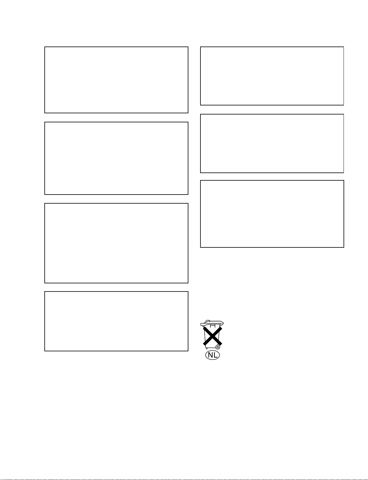
1-3-1. Removing/Reattaching the Upper Lid
n
When removing only the upper lid (from) assembly,
perform the steps 1 to 3.
Upper lid (front) assembly
1. Fully loosen the fixing screw.
2. Slide the knobs on upper lid (front) assembly each in
the inside. (Move the knobs to the outside to fix the
upper lid (front) assembly.
3. Remove the upper lid (front) assembly in the arrow
direction.
Knob
Fixing screw
Upper lid (front) assembly
Knob
If the head clogging is not solved using a cleaning cassette
tape, use cleaning cloth.
For the cleaning using a cleaning cloth, clean according to
the procedure of “4-2-3. Rotary Heads Cleaning” and “4-2-
4. Tape Running Surface of Upper Drum Cleaning”after
confirming the cautions and preparation in “4-2-2. General
Information for Cleaning using Cleaning Cloth”.
SRW-5000/5500
Removal
Installation
When reattaching the upper lid (front) assembly, install in
the reverse order of removal.
n
Tighten the fixing screw as following torque.
Tightening torque: 120 x 10
_2
N.m {12.0 kgf.cm}
1-1
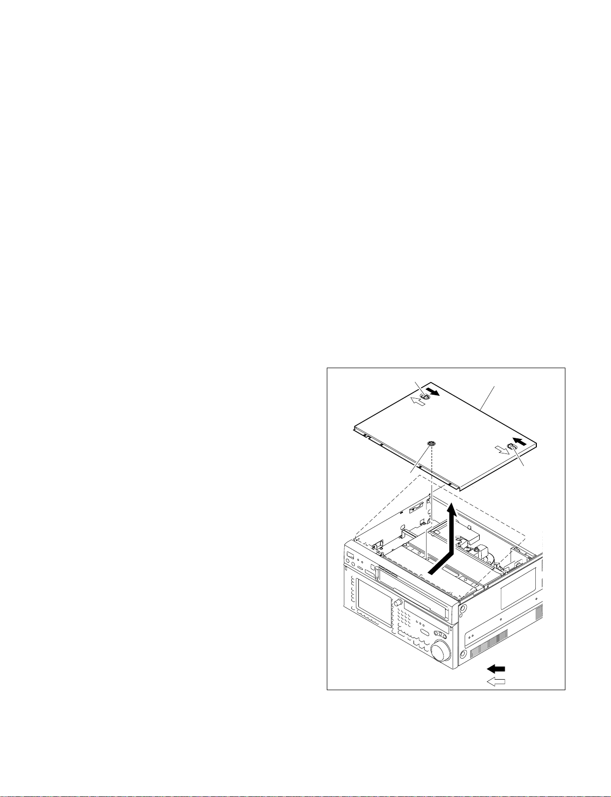
4. Fully loosen the two fixing screws.
5. Remove the upper lid (rear) assembly by moving in
the direction indicated by the arrow.
Fixing screw
Upper lid (front)
assembly
Fixing screw
1-3-2. Removing/Reattaching Bottom Plate
1. Place the unit with the side facing down.
2. Remove the two screws securing the bottom plate.
3. Slide the bottom plate in the arrow A direction to
unhook, the four hooks.
4. Remove the bottom plate in the arrow B direction.
Hooks
BVTT3 x 6
Bottom plate
B
A
BVTT3 x 6
When reattaching, install in the reverse order of removal.
n
Tighten the fixing screws as following torque.
Tightening torque: 120 x 10
_2
N.m {12.0 kgf.cm}
Hooks
When reattaching, install in the reverse order of removal.
1-2
SRW-5000/5500
PSW3 x 6
PSW
3 x 6
Front panel
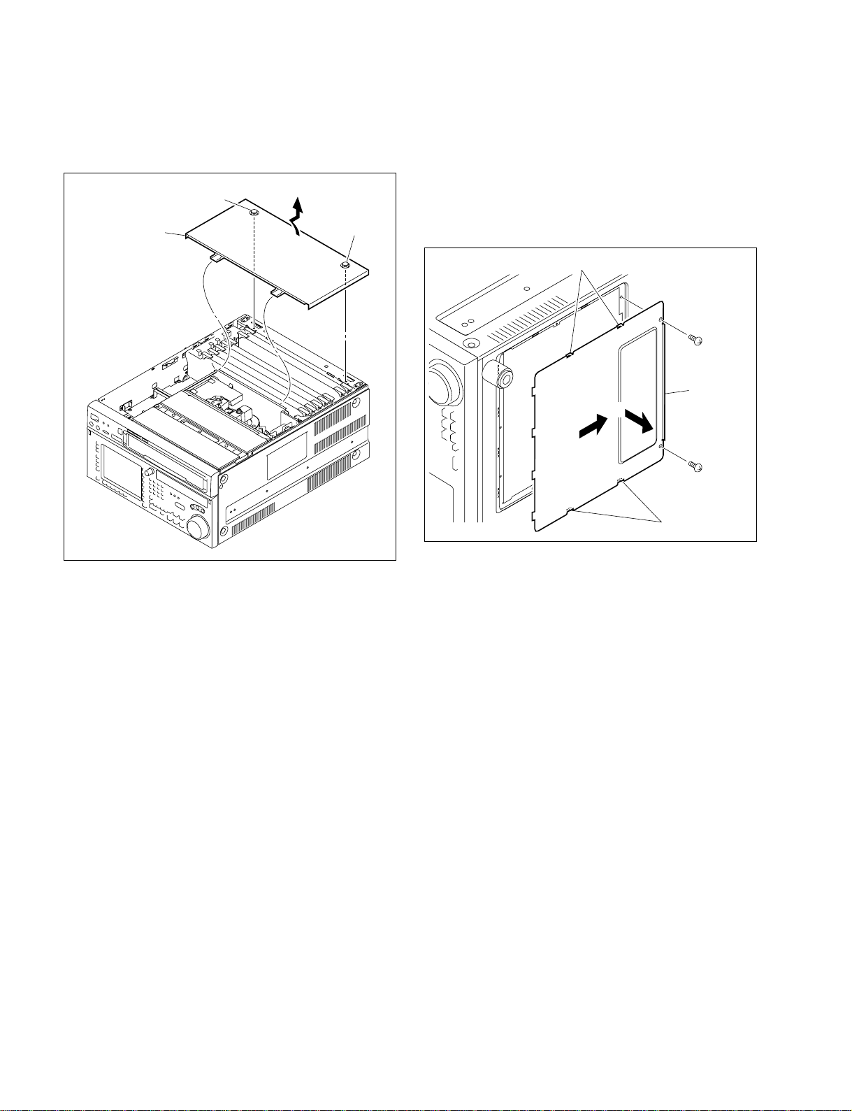
1-3-3. Removing/Reattaching Side Panels
and Front Panel
1. Remove the upper lid (front) assembly and upper lid
(rear) assembly. (Refer to Section 1-3-1.)
2. Remove the nine screws, and side panels (right and
left).
Side panel (left)
B4 x 6
Side panel
(right)
B4 x 6
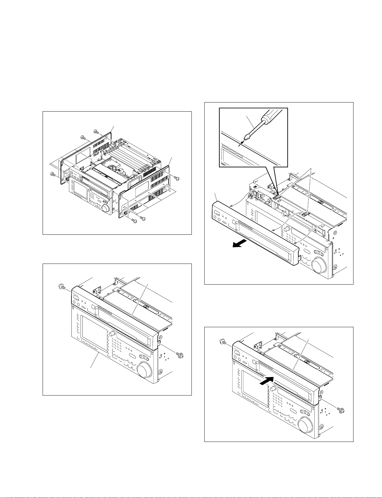
4. Pull the front panel forward while pushing it up.
n
When the front panel is not removed easily, release the
front panel upward, inserting the tip of the flat blade
driver into the warkings shown in the fugure, and then
remove the front panel in the arrow direction.
Flat blade
driver
Markings
(non-painted portion)
B4 x 6
B4 x 6
3. Remove the left and right screws (one each) securing
the front panel.
PSW3 x 6
Lower control panel
Front panel
PSW
3 x 6
Front panel
When reattaching, install in the reverse order of removal.
n
When reattaching the front panel, press it tightly against
the chassis in parallel.
SRW-5000/5500
n
Use of screws other than specified will cause damage of
the internal mechanism. Be sure to use the specified
screws.
1-3

1-3-4. Removing/Reattaching AC Panel
w
For your safety against electric hazards, be sure to turn off
the power and unplug the power cord before removing/
reattaching.
7. Remove the coaxial cables from the guide rail (L).
Cable protector
1. Remove the connector panel assembly.
(Refer to Section 1-4.)
2. Remove the side panel (left). (Refer to Section 1-3-3.)
3. Remove the four screws and two washers securing the
AC panel assembly.
BVTT3 x 6
AC panel assembly
4.
Slide the cable protector in the arrow direction to remove.
BVTT3 x 6
5. Remove the bead tie and open the edge holder.
n
This step is not required when both option HKSR5001 and HKSR-5003 are installed.
Bead tie
Guide rail (L)
Edge holder
Coaxial cables
8. Remove the AC panel assembly in the arrow direction.
9. Discconnect the harnesses from the AC inlet.
10. Pull out the all coaxial cables from the chassis hole
and correctly remove the AC panel assembly.
n
Do not pull the coaxial cables forcedly.
Chassis hole
Coaxial cables
6. Dicconnect the all coaxial cables connected to the
plug-in boards.
n
Hold the plug to remove the coaxial cables in disconnecting the coaxial cables from the connector on the
boards. (Refer to Section 1-12.)
1-4
brown
green/yellow
white
Harnesses
AC panel assembly
AC inlet
When reattaching, install in the reverse order of removal.
m
. Connect the harnesses to the AC inlet correctly.
. For connecting connector of the coaxial cables, refer to
Section 1-12.
SRW-5000/5500
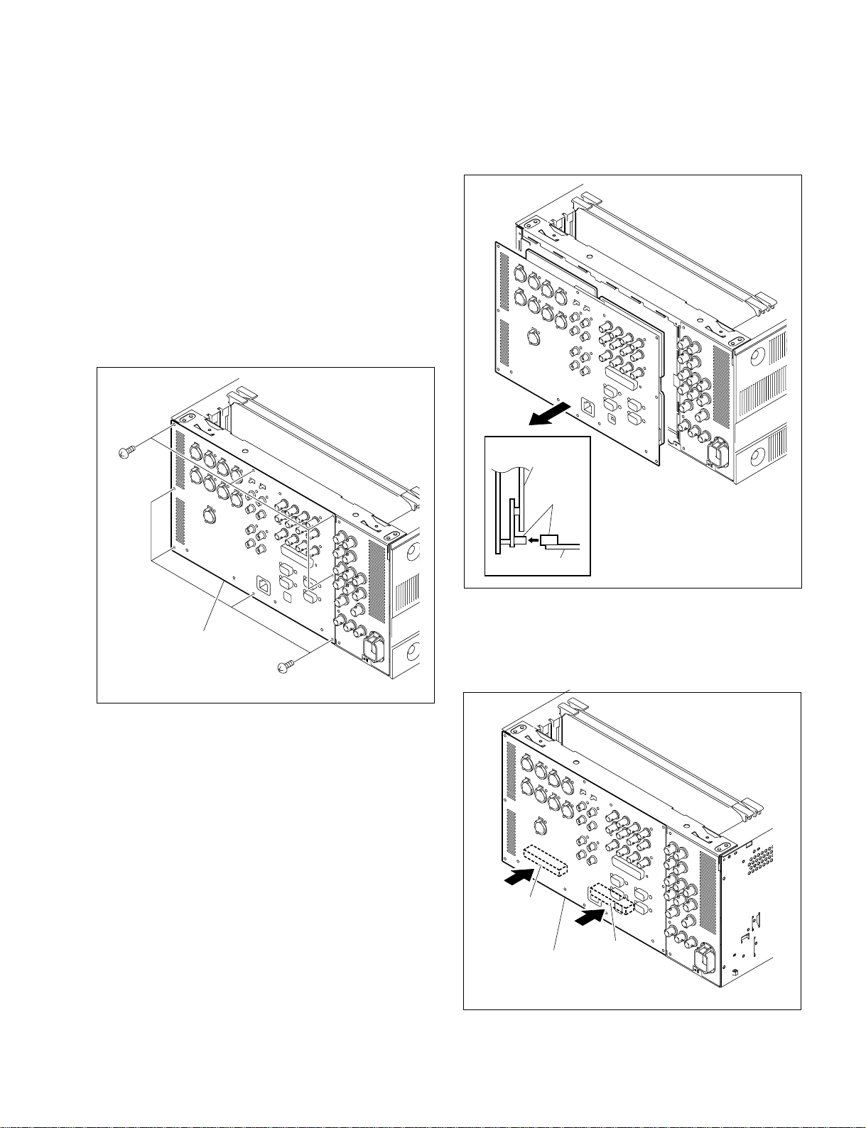
1-4. Removing/Reattaching Connector
Panel Assembly
n
Turn off the power and unplug the power cord before
removing/reattaching.
1. Remove the upper lide (front) asssembly and upper lid
(rear) assembly.
(Refer to Section 1-3-1.)
2. Remove the SS-95 board and APR-62 board.
(Refer to Section 1-12.)
3. Remove the eight screws shown in the figure.
BVTT
3 x 6
4. Push out the connector panel assembly from inside the
unit in the arrow direction, and disconnect the connector connected to the mother board.
Connector panel
assembly
Connectors
Connector panel
assembly
BVTT3 x 6
Mother board
When reattaching, install in the reverse order of removal.
n
Push in portions A of the connector panel assembly, and
connect it firmly to the connector of the mother board.
Portion A
Portion A
Connector panel
assembly
SRW-5000/5500
1-5

1-5. Removing/Reattaching Cassette
Compartment
m
. Turn off the power before starting the removal/installa-
tion.
. The cassette compartment cannot be removed with the
cassette tape inserted. Press the EJECT button with the
power turned on to eject the cassette tape.
If the cassette compartment does not move due to an
electric trouble, take out the cassette tape manually.
(Refer to “1-11. Taking Out the Cassette in Tape Slacking”.)
Removal
1. Remove the upper lid (front) assembly.
(Refer to Section 1-3-1.)
2. Loosen the screw, then remove the cassette compartment bracket assembly.
3. Disconnect the harness from the connector (CN930)
on the CL-29 board. Keep the harness out of the way
of the removal.
4. Hold the cassette compartment at the portions A and
lift up the cassette compartment slightly (by 1 cm).
When the four cassette compartment positioning legs
come off from the four positioning holes on a mechanical deck, shift the cassette compartment backward (by
1 cm) to the position where the cassette lid can be
completely seen when viewed from just above.
5. Hold the cassette compartment at the portions B, then
slowly raise the cassette compartment upward to
remove it.
m
. Being careful not to contact the gear on the right of
the cassette compartment with the chassis, slowly
raise the cassette compartment while slightly sliding
it back-and-forth.
. Never move the cassette compartment to the right
and left. If unnecessary force is applied to right and
left, the gear or part may come off.
. Place the cassette compartment with the cassette lid
up or with cassette compartment positioning legs
down.
(If it is put with the cassette lid down, the flexible
card wire/board might be damaged.)
BVTT3 x 6
(with stopper)
Cassette compartment
bracket assembly
Harness
CN930
Cassette compartment
A
B
A
1-6
SRW-5000/5500
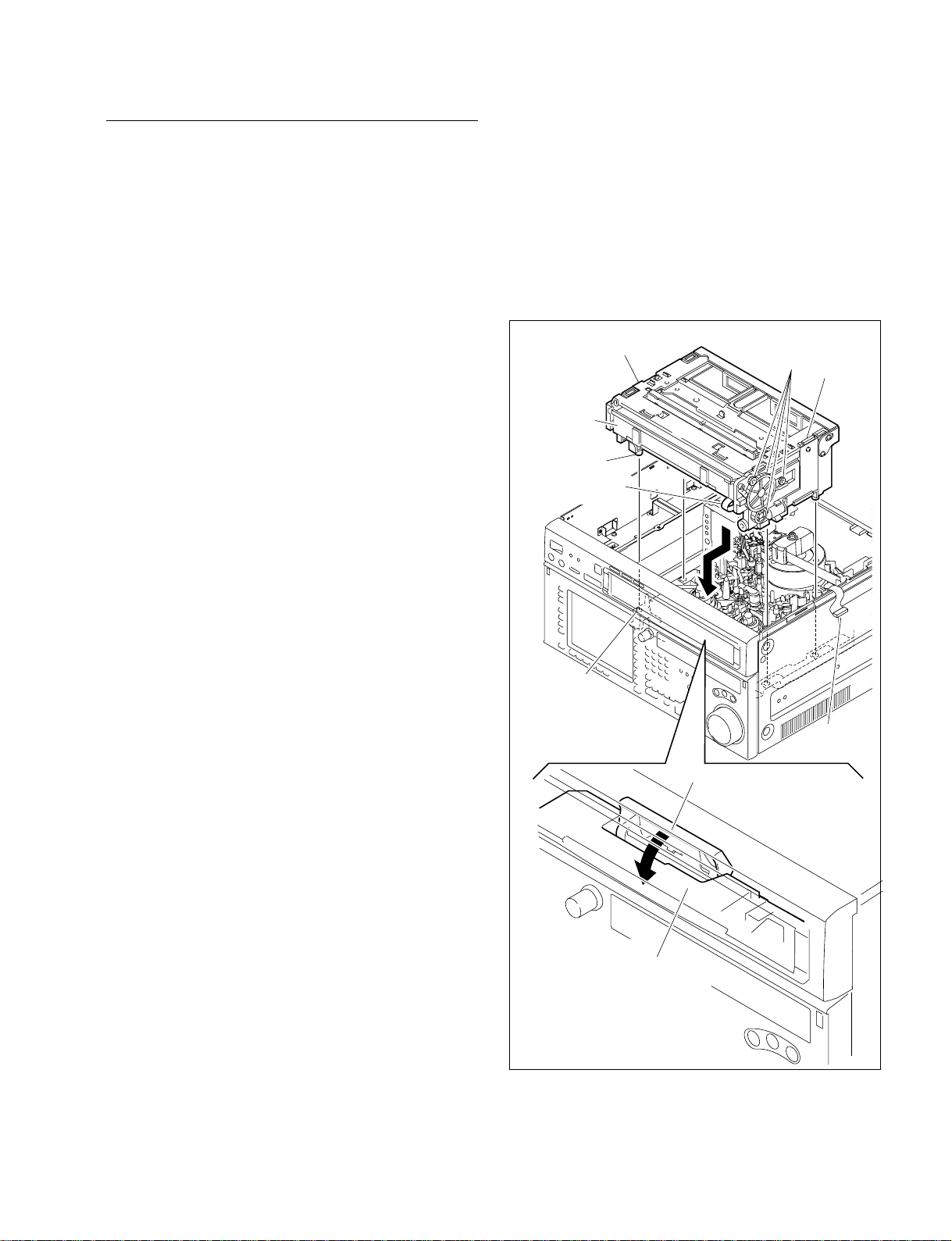
Installation
6. Place the cassette compartment into the unit in the
direction as shown in the figure (with the cassette lid
down).
m
. Being careful not to contact the gear on the right of
the cassette compartment with the chassis, slowly
insert the cassette compartment into the unit while
slightly sliding it back-and-forth.
. Never move the cassette compartment to the right
and left. If unnecessary force is applied to the right
and left, the gear or part may come off.
7.
Press the portions C of the cassette compartment as
shown in the figure, and then fit the four positioning legs
into the four positioning holes in the mechanical deck.
Be sure to attach the cassette compartment while
pressing down the portion D of the SC Guide Assembly by fingers.
If not, the cassette compartment cannot be attached
properly because the back of the stage end of the
cassette compartment blocks portion D.
Cassette compartment
C
Gears
CN930
Cassette lid
Positioning leg
Flexible card
wire/board
Positioning hole
C
Harness
D
SRW-5000/5500
SC guide assembly
8. Connect the harness to the connector (CN930) on the
CL-29 board.
9. Being careful not to pinch the harness, reattach the
cassette compartment bracket assembly.
10. Reattach the upper lid (front) assembly.
1-7
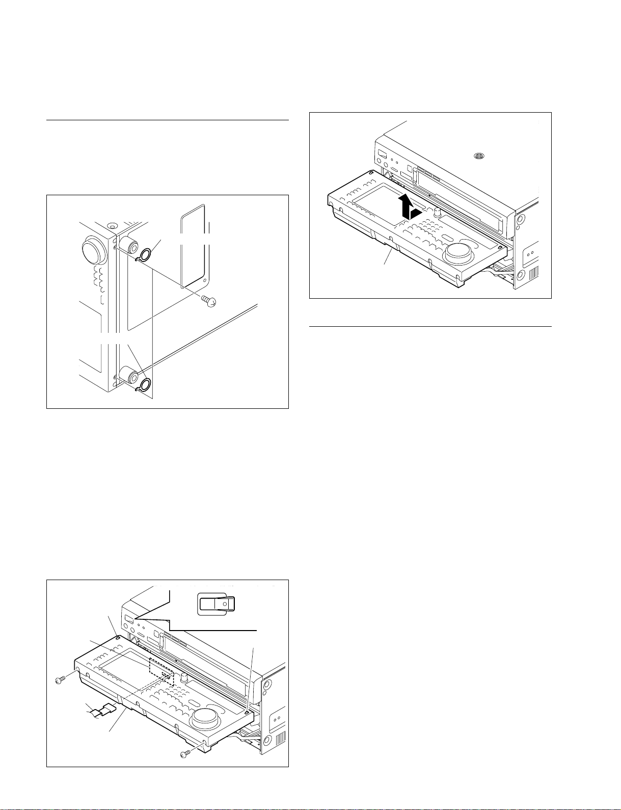
1-6. Removing/Reattaching Lower
Control Panel Unit
Removal
1. Turn off the power of the VTR.
2. If the lock plates are attached, remove the two screws
and remove the lock plates.
Lock plate
B3 x 6
6. Lightly draw the lower control panel unit toward you,
and then lift it upward.
Lower control panel unit
Lock plate
3. Push the left and right unlock buttons, and open the
lower control panel as shown in the figure below.
4. Disconnect the cable from the connector on the system
setup panel.
n
Check that the power of the VTR is turned off before
disconnecting cable. Disconnecting or connecting the
cable in the power-on state will damage the control
panel.
5. Remove the two screws shown in the figure.
POWER
Unlock button
System setup
panel
OI
Power OFF
Unlock button
Installation
When reattaching, install the reverse order of removal, and
use care about following points.
. If the arm is not protruded, press the left and right unlock
buttons, then secure the arm to the 90d position.
. When reattaching the lower control panel unit to the
arms, place the lower control panel with square holes of
the panel aligned to the unlock buttons, slide it slightly
to the VTR to attach.
. Check the screw holes are visible from your side before
tightening the screws.
B3 x 6
Cable
Lower control panel unit
1-8
B3 x 6
SRW-5000/5500

1-7. Circuit Function
System configuration Board name Circuit function Location No.
Digital process DDE-19 (HKSR-5003) Dual link decoder (RGB BRR decode) 4
and DEN-21 (HKSR-5003) Dual link encoder (RGB BRR encode) 3
Video process DPR-209 (HKSR-5002) Digital Betacam PB processor 1
FC-91 (HKSR-5001) Video format converter, Character superimpose @[
HIF-8 HD SDI signal processor (Character superimpose, HD video signal @/
HPR-8 (SRW-5000) HDCAM SR PB video signal processor (BRR decode), HDCAM (ADV !'
HPR-8A (SRW-5500) HDCAM SR PB video signal processor (BRR decode), HDCAM ECC !'
IRC-5 (SRW-5000) HDCAM SR REC processor (Dual-link to RGB convert, BRR encode), !.
IRC-5A (SRW-5500) HDCAM SR REC processor (Dual-link to RGB convert, BRR encode), !.
VPR-79 HDCAM/Digital Betacam ECC outer decoder, HDCAM PB process @-
HD SDI module RX-80 HD SDI Rx module (HD SDI input interface) !,, @'
TX-96 HD SDI Tx module (HD SDI output interface) 2, @=, @;
Audio process APR-62 Audio signal processor, AES/EBU interface, Audio signal D-A @]
AE-31H HDCAM CUE PB EQ 6
CUE-13 HDCAM CUE PB !]
RF process EQ-94 RF equalizer, HDCAM SR ECC encoder/decoders, HDCAM ECC !;
System/servo control SS-95 System control, Servo control, DT control @\
DR-508 Solenoids driver (Pinch, Brakes, Cleaning), Motors driver (Drum, 7
DT-47 DT driver 5
TC-104 TC REC/PB circuit, TC/FULL erase OSC ![
Mech, deck driver/ CCM-15 Threading motor $]
sensor HN-268 Pinch and Cleaning sloenoids connection, Tape end sensor connection $=
PTC-99 Cassette’s holes sensor #.
PTC-102 Threading FG $[
SE-606A Loop antenna board $/
TR-119 S tension sensor $-
TR-120 T tension sensor, Threading-end and Unthreading-end sensors #,
(BRR decode, Video signal JOG/VAR process)
process, RGB to Dual-link convert)
PB)/Digital Betacam video signal processor (Slow process, SD-HD
up convert), PB digital audio sample-change (Sampling-rate convert,
Non audio process)
outer decoder, HDCAM PB process (BRR decode, Concealment,
4:2:2-3:1:1 pre-filter), HDCAM (ADV PB)/Digital Betacam video signal
processor (Slow process, SD-HD up convert), PB digital audio
sample-change (Sampling-rate convert, Non audio process)
Master timing generator, Internal HD video signal generator
HDCAM REC processor (4:2:2-3:1:1 pre-filter, BRR encoder, ECC
encoder), Master timing generator, Internal HD video signal generator
(BRR decode, Concealment, 4:2:2-3:1:1 pre-filter), HD-SD down
converter, SD video signal processor (Character superimpose,
SD composite encode, SDI output interface)
inner decoder
Capstan, Reels, Threading, Reel shift, Cassette up/down),
REC inhibit sensors, Reel position sensors
(Continued)
SRW-5000/5500
1-9

System configuration Board name Circuit function Location No.
Cassette compartment LP-81 Lamp of cassette compartment $;
PC-70 Cassette-in sensors, Cassette size sensor $'
CL-29 Cassette up/down motor, Cassette down sensors $\
Front panel DIO-69 Connection board, Memory label reader/writer 9
FP-131 Memory card slot and interface, NV-RAMs, Lower control panel !-
connection
FP-132 Memory card slot 0
HP-110 Upper control panel function (PHONES) 8
LED-386 Upper control panel function (Format indicators) #]
SWC-43 Upper control panel function (Remote/Eject SW, CH-condition/Error/ #[
Lower control panel CN-2511 LCD connection board #-
CP-382 Lower control panel function controller, LCD driver #/
KY-526 Menu selection keys #=
KY-527 VTR function keys @,
PTC-101 Search dial @.
Connector panel CP-376 (SRW-5000) Connector board (Analog audio, Monitor, Time code) #\
CP-376A (SRW-5500)
CP-377 Connector board (Analog video, Ethernet) #;
CP-378 Connector board (Digital audio (AES/EBU), remote control connectors) #'
Other MB-964 Motherboard !\
Warning indicators)
1-10
SRW-5000/5500
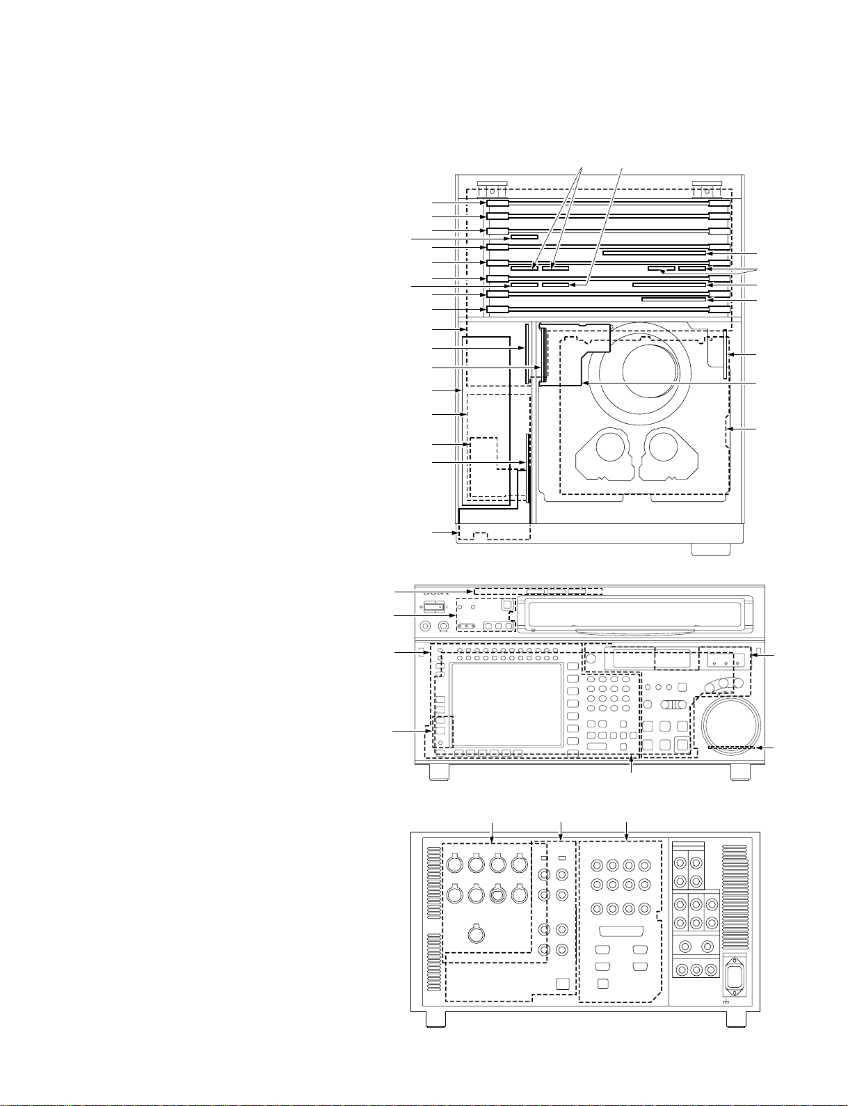
1-8. Location of Main Parts
1-8-1. Printed Circuit Boards and Power
Supply Unit Locations
@; @'
AE-31H..................................... 6
APR-62 ..................................... @]
CN-2511 ................................... #-
CP-376/CP-376A...................... #\
CP-377 ...................................... #;
CP-378 ...................................... #'
CP-382 ...................................... #/
CUE-13..................................... !]
DDE-19 (HKSR-5003) ............. 4
DEN-21 (HKSR-5003) ............. 3
DIO-69...................................... 9
DPR-209 (HKSR-5002) ........... 1
DR-508 ..................................... 7
DT-47 ....................................... 5
EQ-94 ....................................... !;
FC-91 (HKSR-5001) ................ @[
FP-131 ...................................... !-
FP-132 ...................................... 0
HIF-8 ........................................ @/
HP-110...................................... 8
HPR-8/HPR-8A ........................ !'
IRC-5/IRC-5A .......................... !.
KY-526 ..................................... #=
KY-527 ..................................... @,
LED-386 ................................... #]
MB-964..................................... !\
PTC-101 ................................... @.
RX-80 ....................................... !,
RX-80 (HKSR-5003)................ @'
SS-95 ........................................ @\
SWC-43 .................................... #[
TC-104...................................... ![
TX-96 ....................................... 2
TX-96 (HKSR-5001)................ @=
TX-96 (HKSR-5003)................ @;
VPR-79 ..................................... @-
Power supply unit ..................... !=
#]
#[
#=
#-
@=
!,
@\
@]
@[
@@/
!.
!'
!;
!\
!]
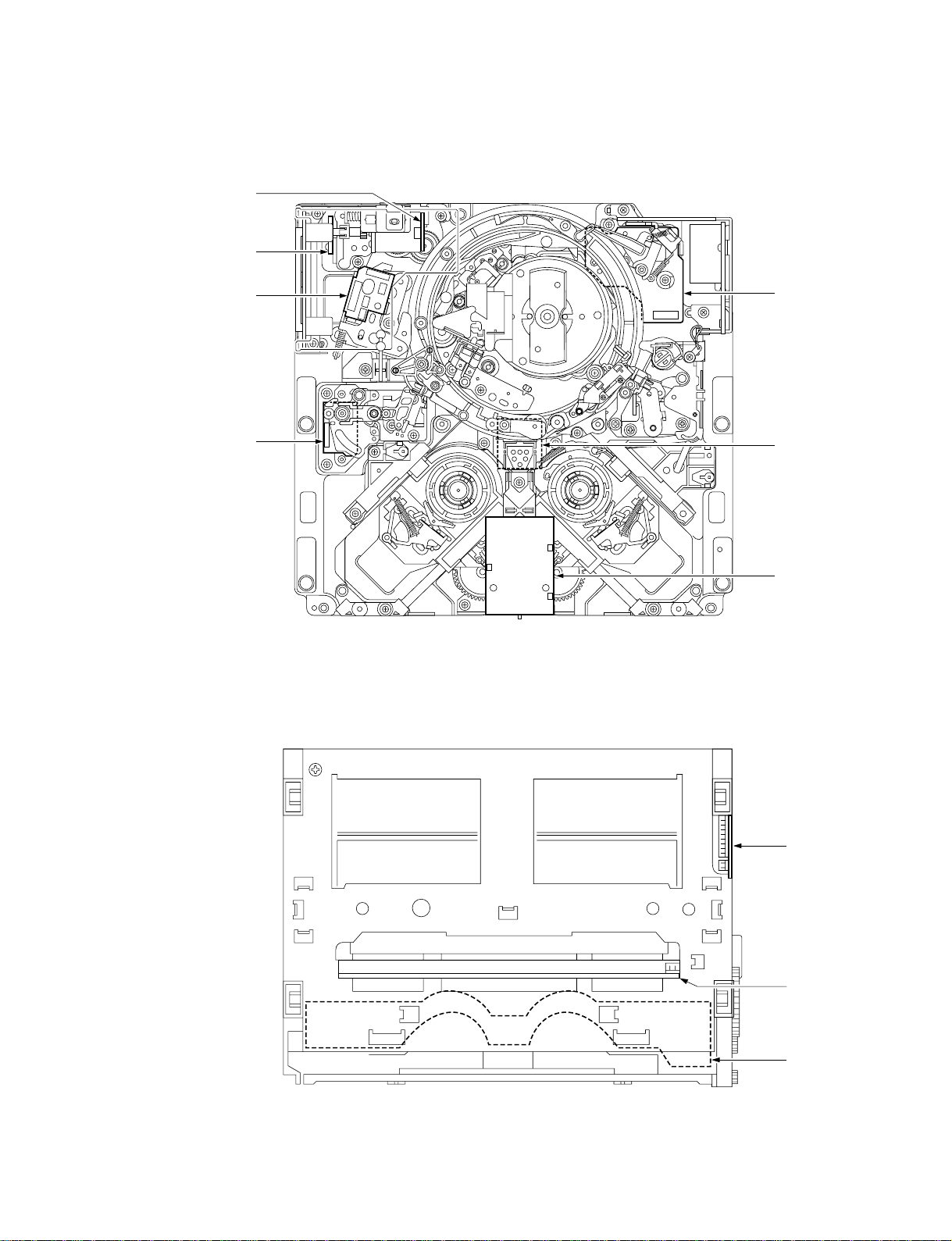
CCM-15 ............ $]
CL-29................ $\
HN-268 ............. $=
LP-81 ................ $;
PC-70 ................ $'
PTC-102 ........... $[
PTC-99 ............. #.
SE-606A ........... $/
TR-119.............. $-
TR-120.............. #,
$]
$[
$=
#,
$-
#.
$/
< Top View of Mechanical Deck >
$\
1-12
$;
$'
< Top View of Cassette Compartment >
SRW-5000/5500
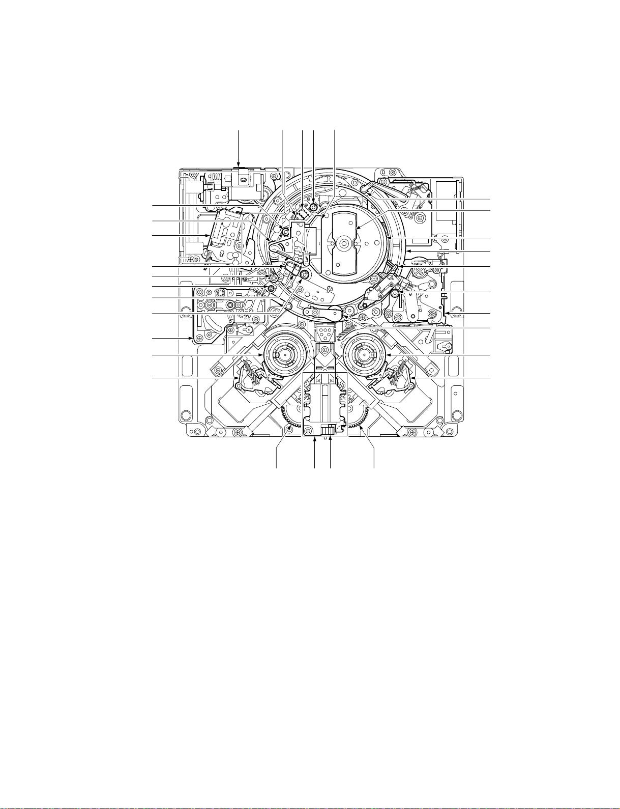
1-8-2. Main Mechanical Part Locations
@\
@]
@[
@=
@@/
!.
!,
!'
!;
!\
@;
@, @.
@' #/
1
2
3
4
5
6
7
8
9
!/
INDEX
1 T tension regulator assembly
2 Brush slipring assembly
3 Head drum
4 Threading ring
5 Audio/TC head cleaner
6 TG-10 tape guide
7 T drawer arm assembly
8 Pinch roller assembly
9 T reel table
0 T brake assembly
!- T drive gear
!= Worm assembly
![ Motor holder assembly
!] S drive gear
!\ S brake assembly
!] ![
< Top View of Mechanical Deck >
!= !-
!; S reel table
!' S tension regulator assembly
!, TG-2 tape guide
!. CTL head
@/ Tape cleaner
@- TG-0 tape guide
@= Full-erase head
@[ Pinch press assembly
@] Capstan motor
@\ TG-4 tape guide
@; Gear box assembly
@' Audio/TC head
@, Audio/TC erase head
@. TG-3 tape guide
#/ Video head cleaner assembly
SRW-5000/5500
1-13

1-9. Function and Location of Sensors
1
2
3
4
5
!,
!'
!;
!]
!\
< Top View of Mechanical Deck >
6
 Loading...