

Sony SRW-5100 Operation Manual

HD DIGITAL VIDEOCASSETTE PLAYER
SRW-5100
FORMAT CONVERTER BOARD
HKSR-5001
DIGITAL BETACAM/HDCAM PROCESSOR BOARD
HKSR-5802
ADVANCED PROCESSOR BOARD
HKSR-5103
OPERATION MANUAL [English]
1st Edition
Important Safety Instructions
• Read these instructions.
• Keep these instructions.
• Heed all warnings.
• Follow all instructions.
• Do not use this apparatus near water.
• Clean only with dry cloth.
• Do not block any ventilation openings.
Install in accordance with the manufacturer's
instructions.
• Do not install near any heat sources such as radiators,
heat registers, stoves, or other apparatus (including
amplifiers) that produce heat.
• Do not defeat the safety purpose of the polarized or
grounding-type plug. A polarized plug has two blades
with one wider than the other. A grounding type plug
has two blades and a third grounding prong. The wide
blade or the third prong are provided for your safety. If
the provided plug does not fit into your outlet, consult an
electrician for replacement of the obsolete outlet.
• Protect the power cord from being walked on or pinched
particularly at plugs, convenience receptacles, and the
point where they exit from the apparatus.
• Only use attachments/accessories specified by the
manufacturer.
• Use only with the cart, stand, tripod, bracket,
or table specified by the manufacturer, or sold
with the apparatus.
When a cart is used, use caution when moving
the cart/apparatus combination to avoid injury from tipover.
• Unplug this apparatus during lightning storms or when
unused for long periods of time.
• Refer all servicing to qualified service personnel.
Servicing is required when the apparatus has been
damaged in any way, such as power-supply cord or plug
is damaged, liquid has been spilled or objects have fallen
into the apparatus, the apparatus has been exposed to
rain or moisture, does not operate normally, or has been
dropped.
WARNING
To reduce the risk of fire or electric shock,
do not expose this apparatus to rain or
moisture.
To avoid electrical shock, do not open the
cabinet. Refer servicing to qualified
personnel only.
THIS APPARATUS MUST BE EARTHED.
This symbol is intended to alert the user to
the presence of uninsulated “dangerous
voltage” within the product’s enclosure
that may be of sufficient magnitude to
constitute a risk of electric shock to
persons.
This symbol is intended to alert the user to
the presence of important operating and
maintenance (servicing) instructions in
the literature accompanying the
appliance.
When installing the installation space must be secured in
consideration of the ventilation and service operation.
• Do not block the ventilation slots at the left side and right
side panels, and vents of the fans.
• Leave a space around the unit for ventilation.
• Leave more than 40 cm of space in the rear of the unit to
secure the operation area.
When the unit is installed on the desk or the like, leave at
least 4 cm of space in the left and right sides. Leaving 40
cm or more of space above the unit is recommended for
service operation.
WARNING: THIS WARNING IS APPLICABLE
FOR USA ONLY.
If used in USA, use the UL LISTED power cord specified
below.
DO NOT USE ANY OTHER POWER CORD.
Plug Cap Parallel blade with ground pin (NEMA 5-15P
Configuration)
Cord Type SJT, three 16 or 18 AWG wires
Length Minimum 1.5m (4 ft .11in.), Less than 2.5 m
(8 ft .3 in.)
Rating Minimum 10A, 125V
Using this unit at a voltage other than 120V may require
the use of a different line cord or attachment plug, or both.
To reduce the risk of fire or electric shock, refer servicing
to qualified service personnel.
WARNING: THIS WARNING IS APPLICABLE
FOR OTHER COUNTRIES.
2

1. Use the approved Power Cord (3-core mains lead) /
Appliance Connector / Plug with earthing-contacts that
conforms to the safety regulations of each country if
applicable.
2. Use the Power Cord (3-core mains lead) / Appliance
Connector / Plug conforming to the proper ratings
(Voltage, Ampere).
If you have questions on the use of the above Power Cord
/ Appliance Connector / Plug, please consult a qualified
service personnel.
CAUTION
The apparatus shall not be exposed to dripping or
splashing. No objects filled with liquids, such as vases,
shall be placed on the apparatus.
Do not install the appliance in a confined space, such as
book case or built-in cabinet.
CAUTION
The unit is not disconnected from the AC power source
(mains) as long as it is connected to the wall outlet, even if
the unit itself has been turned off.
For the customers in the U.S.A. (for SRW-5100)
This equipment has been tested and found to comply with
the limits for a Class A digital device, pursuant to Part 15
of the FCC Rules. These limits are designed to provide
reasonable protection against harmful interference when
the equipment is operated in a commercial environment.
This equipment generates, uses, and can radiate radio
frequency energy and, if not installed and used in
accordance with the instruction manual, may cause
harmful interference to radio communications. Operation
of this equipment in a residential area is likely to cause
harmful interference in which case the user will be
required to correct the interference at his own expense.
You are cautioned that any changes or modifications not
expressly approved in this manual could void your
authority to operate this equipment.
All interface cables used to connect peripherals must be
shielded in order to comply with the limits for a digital
device pursuant to Subpart B of Part 15 of FCC Rules.
For the customers in Europe
This product with the CE marking complies with both the
EMC Directive and the Low Voltage Directive issued by
the Commission of the European Community.
Compliance with these directives implies conformity to
the following European standards:
• EN60065 : Product Safety (for SRW-5100)
• EN55103-1 : Electromagnetic Interference (Emission)
• EN55103-2 : Electromagnetic Susceptibility (Immunity)
This product is intended for use in the following
Electromagnetic Environment: E4 (controlled EMC
environment, ex. TV studio)
For the customers in Europe
The manufacturer of this product is Sony Corporation, 17-1 Konan, Minato-ku, Tokyo, Japan.
The Authorized Representative for EMC and product
safety is Sony Deutschland GmbH, Hedelfinger Strasse
61, 70327 Stuttgart, Germany. For any service or
guarantee matters please refer to the addresses given in
separate service or guarantee documents.
This apparatus shall not be used in the residential area.
For the customers in Europe, Australia and New
Zealand
WARNING
This is a Class A product. In a domestic environment, this
product may cause radio interference in which case the
user may be required to take adequate measures.
WARNING
Excessive sound pressure from earphones and headphones
can cause hearing loss.
In order to use this product safely, avoid prolonged
listening at excessive sound pressure levels.
For the customers in Europe
Hereby, Sony Corporation, declares that this SRW-5100 is
in compliance with the essential requirements and other
relevant provisions of the Directive 1999/5/EC.
For details, please access the following URL :
http://www.compliance.sony.de/
Pour les clients en Europe
Par la présente Sony Corporation déclare que l'appareil
SRW-5100 est conforme aux exigences essentielles et aux
autres dispositions pertinentes de la directive 1999/5/CE.
Pour toute information complémentaire, veuillez consulter
l’URL suivante: http://www.compliance.sony.de/
Für Kunden in Europa
Hiermit erklärt Sony Corporation, dass sich das Gerät
SRW-5100 in Übereinstimmung mit den grundlegenden
Anforderungen und den übrigen einschlägigen
Bestimmungen der Richtlinie 1999/5/EG befindet.
Weitere Informationen erhältlich unter:
http://www.compliance.sony.de/
Per i clienti in Europa
Con la presente Sony Corporation dichiara che questo
SRW-5100 è conforme ai requisiti essenziali ed alle altre
disposizioni pertinenti stabilite dalla direttiva 1999/5/CE.
Per ulteriori dettagli, si prega di consultare il seguente
URL: http://www.compliance.sony.de/
Para los clientes de Europa
Por medio de la presente Sony Corporation declara que el
SRW-5100 cumple con los requisitos esenciales y
3
cualesquiera otras disposiciones aplicables o exigibles de
la Directiva 1999/5/CE.
Para mayor información, por favor consulte el siguiente
URL: http://www.compliance.sony.de/
Voor de klanten in Europa
Hierbij verklaart Sony Corporation dat het toestel SRW5100 in overeenstemming is met de essentiële eisen en de
andere relevante bepalingen van richtlijn 1999/5/EG.
Nadere informatie kunt u vinden op:
http://www.compliance.sony.de/
For kunder i Europa
Härmed intygar Sony Corporation att denna SRW-5100
står I överensstämmelse med de väsentliga egenskapskrav
och övriga relevanta bestämmelser som framgår av
direktiv 1999/5/EG.
För ytterligare information gå in på följande hemsida:
http://www.compliance.sony.de/
Para os clientes da Europa
Sony Corporation declara que este SRW-5100 está
conforme com os requisitos essenciais e outras disposições
da Directiva 1999/5/CE.
Para mais informacoes, por favor consulte a seguinte URL:
http://www.compliance.sony.de/
For kunder i Europa
Undertegnede Sony Corporation erklærer herved, at
følgende udstyr SRW-5100 overholder de væsentlige krav
og øvrige relevante krav i direktiv 1999/5/EF.
For yderligere information gå ind på følgende
hjemmeside: http://www.compliance.sony.de/
Pro zákazníky v Evropě
Sony Corporation tímto prohlašuje, že tento SRW5100 je ve shodě se základními požadavky a dalšími
příslušnými ustanoveními směrnice 1999/5/ES.
Podrobnosti lze získat na následující URL:
http://www.compliance.sony.de/
Euroopa klientidele
Sony Corporation kinnitab käesolevaga seadme SRW5100 vastavust 1999/5/EÜ direktiivi põhinõuetele ja
nimetatud direktiivist tulenevatele teistele asjakohastele
sätetele.
Üksikasjalikum info: http://www.compliance.sony.de/.
Európai vásárlóink fi gyelmébe
Alulírott, Sony Corporation nyilatkozom, hogy a(z)
SRW-5100 megfelel a vonatkozó alapvető
követelményeknek és az 1999/5/EC irányelv egyéb
előírásainak.
További információkat a következő weboldalon
találhat: http://www.compliance.sony.de/
Euroopassa oleville asiakkaille
Sony Corporation vakuuttaa täten että SRW-5100
tyyppinen laite on direktiivin 1999/5/EY oleellisten
vaatimusten ja sitä koskevien direktiivin muiden ehtojen
mukainen.
Halutessasi lisätietoja, käy osoitteessa:
http://www.compliance.sony.de/
For kundene i Europa
Sony Corporation erklærer herved at utstyret SRW-5100
er i samsvar med de grunnleggende krav og øvrige
relevante krav i direktiv 1999/5/EF.
For flere detaljer, vennligst se:
http://www.compliance.sony.de/
Για τους πελάτες στην Eυρώπη
Με την παρούσα η Sony Corporation δηλώνει τι
SRW-5100 συμμορφώνεται προς της ουσιώδεις
απαιτήσεις και τις λοιπές σχετικές διατάξεις της
οδηγίας 1999/5/ΕΚ..
Για λεπτομέρειες παρακαλούμε πως ελένξετε
την ακλουθη σελίδα του διαδικτύου:
http://www.compliance.sony.de/
Dotyczy klientów z Europy
Niniejszym Sony Corporation oświadcza, że SRW5100 jest zgodne z zasadniczymi wymaganiami oraz
innymi stosownymi postanowieniami Dyrektywy
1999/5/WE.
Szczegółowe informacje znaleźć można pod
następującym adresem URL:
http://www.compliance.sony.de/
4

Pentru clienţii din Europa
Prin prezenta, Sony Corporation declară că acest
SRW-5100 respectă cerinţele esenţiale și este în
conformitate cu prevederile Directivei 1995/5/EC.
Pentru detalii, vă rugăm accesaţi următoarea adresă:
http://www.compliance.sony.de/
Pre zákazníkov v Európe
Sony Corporation týmto vyhlasuje, že SRW-5100
spĺňa základné požiadavky a všetky príslušné
ustanovenia Smernice 1999/5/ES.
Podrobnosti získate na nasledovnej webovej adrese:
http://www.compliance.sony.de/
Za stranke v Evropi
Sony Corporation izjavlja, da je ta SRW-5100 v skladu
z bistvenimi zahtevami in ostalimi relevantnimi
določili direktive 1999/5/ES.
Za podrobnosti vas naprošamo, če pogledate naURL:
http://www.compliance.sony.de/
For the customers in the USA
Lamp in this product contains mercury. Disposal of these
materials may be regulated due to environmental
considerations. For disposal or recycling information,
please contact your local authorities or the Electronic
Industries Alliance (www.eiae.org).
For the customers in Taiwan only
5

Table of Contents
Chapter 1 Overview
1-1 Features ......................................................................... 10
1-1-1 Features of the SRW-5100..............................................10
1-1-2 Features of the Control Panel..........................................12
1-2 Optional Accessories ................................................... 14
Chapter 2 Locations and Functions of Parts
2-1 Control Panel................................................................. 15
2-1-1 Upper Control Panel .......................................................16
2-1-2 Lower Control Panel.......................................................17
2-1-3 System Set-Up Panel.......................................................22
2-2 Connector Panel ........................................................... 23
Chapter 3 Setting Up the Unit
3-1 Connecting External Equipment ................................. 27
3-2 Reference Signals......................................................... 29
3-3 Handling Cassettes....................................................... 30
3-4 Using a “Memory Stick” ............................................... 32
Chapter 4 Menu Settings
4-1 Registering and Storing Menu Settings...................... 34
3-1-1 Making HD Digital Connections .................................... 27
3-1-2 Making NTSC/PAL Digital Connections.......................28
3-2-1 Reference Signals for Output Video ...............................29
3-2-2 Reference Signal Connections ........................................29
3-3-1 Recommended Cassettes................................................. 30
3-3-2 Inserting and Ejecting Cassettes .....................................31
3-3-3 Preventing Accidental Erasure........................................ 31
3-4-1 Notes on “Memory Stick”...............................................32
4-1-1 Menu Configuration........................................................34
4-1-2 Changing Menu Settings.................................................34
6
Table of Contents

4-1-3 Registering VTR SETUP Menu Items to Function
Keys.................................................................................35
4-1-4 VTR Memory Bank Function .........................................36
4-1-5 “Memory Stick” Operations............................................38
4-1-6 Adding Titles to the Data ................................................43
4-1-7 Details on VTR Memory Bank and “Memory Stick”
Functions .........................................................................44
4-1-8 “Memory Stick” Data Compatibility ..............................44
4-1-9 Automatic Reading from a VTR Bank at Power On.......45
4-1-10 Saving and Recalling DEFAULT Settings on a Bank ..45
4-1-11 Saving and Recalling DEFAULT Settings in a “Memory
Stick”...............................................................................46
4-1-12 Recalling VTR SETUP Data for the SRW-5000/5500 to
the VTR Memory Bank...................................................46
4-2 HOME Menu ...................................................................48
4-2-1 Selecting the Output Signals ...........................................49
4-2-2 Still-Picture Output (FREEZE).......................................49
4-2-3 Setting the Preroll Time (PREROLL TIME)..................49
4-2-4 Selecting DMC Playback (DMC) ...................................49
4-2-5 Setting the Stop Code (STOP CODE) ............................50
4-3 TC Menu .........................................................................53
4-3-1 Setting the Time Data (TIMER SEL/RESET/SET/
HOLD).............................................................................54
4-3-2 Setting the Time Code Reader (TCR SEL).....................54
4-3-3 Selecting the Drop Frame Mode (DF/NDF) ...................55
4-3-4 Selecting the Content of the Second Time Code Display
Area (TC2 SEL) ..............................................................55
4-3-5 Selecting CTL Display Mode (TAPE TIMER) ..............55
4-3-6 Presetting Pulldown Time Code (PDPSET MENU)
(when HKSR-5001 is installed) ......................................55
4-3-7 Presetting for Conversion from Frame Time Code
(TCCONV MENU) .........................................................56
4-3-8 Displaying the Pulldown Time Code (PDTC DISP) (when
HKSR-5001 is installed) .................................................58
4-3-9 Superimposition of Character Information (FC CHARA/
CHARA SUPER/H-POS/V-POS)...................................58
4-4 CUE Menu.......................................................................61
4-4-1 Selecting a Multi-Cue Mode...........................................62
4-4-2 Registering Cue Points....................................................62
4-4-3 Erasing Cue Point Data ...................................................64
4-4-4 Prerolling to a Cue Point.................................................64
4-4-5 Changing a Cue Point Into an Edit Point ........................65
4-4-6 TELE FILE Menu ...........................................................65
4-5 VIDEO Menu...................................................................80
Table of Contents
7

Chapter 5 Playback
4-5-1 Adjusting the Output Video Signal (MASTER to
FINE)...............................................................................81
4-6 AUDIO Menu .................................................................. 84
4-6-1 Digital Audio Output Signal Source Track Selection
(DIGOUT EXCHNG) .....................................................84
4-6-2 Digital Audio Output Signal Source Track Selection
(SDOUT EXCHNG) .......................................................85
4-7 SET UP Menu................................................................. 87
4-7-1 VTR SETUP Menu.........................................................88
4-7-2 PANEL SETUP Menu ....................................................90
5-1 Preparing for Playback................................................. 92
5-1-1 Setting Switches and Menus ...........................................92
5-1-2 Selecting Audio Signals To Be Monitored .....................92
5-1-3 Adjusting the Audio Playback Level ..............................93
5-1-4 Audio Level Meter Display Modes.................................94
5-1-5 Selecting the HD-SD Conversion Mode.........................94
5-2 Playback ........................................................................ 95
5-2-1 Normal-Speed Playback..................................................95
5-2-2 Variable Speed Playback ................................................95
5-2-3 Capstan Override Playback.............................................97
5-2-4 DMC Playback................................................................97
5-2-5 Playing Back Non-audio Data ........................................99
5-2-6 Playing Back Specified Section Repeatedly (Automatic
Repeat Playback).............................................................99
Appendix
8
Table of Contents
Maintenance ...................................................................... 100
Head Cleaning ........................................................................100
Moisture Condensation...........................................................100
Specifications.................................................................... 101
Error Messages and Warning Messages ........................ 104
Error Messages .......................................................................104
Warning Messages..................................................................105
Error Log Menu......................................................................107
Glossary............................................................................. 109
Menu List ........................................................................... 111
Items Relating to Operations of This Unit (Nos. 001 to ...) ...111

Items Relating to Operation Panels (Nos. 101 to ...) ..............114
Items Relating to Remote Interface (Nos. 201 to ...) ..............117
Items Relating to Editing (Nos. 301 to ...)..............................118
Items Relating to Prerolling (Nos. 401 to ...)..........................119
Items Relating to Recording Protection (Nos. 501 to ...)........120
Items Relating to the Time Code (Nos. 601 to ...)..................121
Items Relating to the Video Control (Nos. 706 to ...).............125
Items Relating to the Audio Control (Nos. 807 to ...).............128
Items Relating to Digital Processing (Nos. 902 to ...) ............133
Items Relating to the Pulldown Control (Nos. A01 to ...) ......138
Other Items (Nos. T01 to ...)...................................................140
MPEG-4 Visual Patent Portfolio License ........................145
Index ...................................................................................146
Table of Contents
9

Chapter 1 Overview
Overview
1-1 Features
1-1-1 Features of the SRW-5100
The SRW-5100 is a high-definition digital videocassette
player using the HDCAM-SR
the conventional SRW-5000 in size and weight, and 4:2:2/
1080/50P or 60P signal playback and playback of HQ
recording of 4:4:4 (RGB) signal can be supported.
1) HDCAM-SR is a trademark of Sony Corporation.
HDCAM-SR format
The HDCAM-SR format exploits technological advances
in signal processing and magnetic recording, to provide
functionality comparable to that of the HDCAM format,
while offering HD digital recording and playback with
high image and sound quality.
The technology incorporated in this unit includes the
following.
• Highly efficient and mild data compression using newly
developed MPEG-4 Studio Profile
• Powerful error-correcting codes
• The drum with a high-performance, high-accuracy head,
together with a new auto-tracking technique, yielding
highly reliable narrow track playback.
These technologies allow 120 minutes of playback of an
HDCAM-SR cassette (L type), the same size as the
HDCAM cassette.
Digital signal processing
In this unit, 4:2:2/4:4:4 component video signals obtained
by quantization according to ITU-R709, SMPTE 274M
and BTA S-002B (SMPTE 260M) are compressed using
MPEG-4 Studio Profile. Audio signals are processed
without compression.
Bit rate reduction encoder
The component video signal undergoes frame shuffling. It
is then compressed by a process in which it is subjected to
DCT (discrete cosine transform) or DPCM (differential
1)
format. It is comparable to
Chapter
pulse code modulation), quantization control, and variable
length word encoding. This is the core of the newly
developed MPEG-4 Studio Profile. Interlaced signals are
compressed in fields and progressive signals are
compressed in frames.
ECC encoder
The outer ECC (Error Correction Code) is added to the
compressed video and audio data, followed by the inner
ECC, ID data, and sync data. Reed-Solomon codes are
employed in this error correction system.
Channel coding
Video and audio data with the ECC added is recorded in
the form of serial data. The HDCAM-SR format adopts a
scrambled i-NRZ channel coding system, giving
consideration to off-track and noise characteristics.
Playback signal processing
The playback digital signal is equalized by an equalizer
circuit. It then passes powerful inner and outer ECCs
which can correct dropouts in the reproduced signal. It
further goes through an error concealment circuit to have
errors still remaining in the signal rectified.
Output interface
Component video data is converted into serial data and
multiplexed with audio data and time code, then output in
the HD SDI format.
With an HD-SD converter board installed, the unit can
output both D1 SDI and analog composite signals.
Besides audio data is output as digital data multiplexed
with the HD SDI signal, it is also output via an AES/EBU
digital interface. Analog data converted from digital data is
also provided for monitoring.
Advanced playback functions
High-quality digital recording
The HDCAM-SR format uses a component system to
record video signals. The 12-channel audio signal is
recorded in 48-kHz, 24-bit format. A unique and powerful
error correction circuit and concealment circuit are used in
digital signal processing.
1
10
1-1 Features

Accurate and stable video signal output is made possible
by setting and adjusting the internal digital video
processor.
Playback modes
HDCAM-SR format
The following playback formats can be selected:
• For playback of a 4:2:2 signal
1080×1920: 23.98PsF/24PsF/25PsF/29.97PsF/30PsF, 50i/
59.94i/60i, 50P/59.94P/60P
720×1280: 50P/59.94P
Double-speed playback
Recordings made with any of the following applicable
system settings can be played back at double speed, and by
adding the playback signal to a dual link output signal, the
transmission time to a server, etc. can be shortened.
Chapter 1 Overview
Applicable system settings:
4:2:2 signal
1080×1920: 23.98PsF/24PsF/25PsF/29.97PsF/30PsF, 50i/
59.94i/60i
720×1280: 50P/59.94P
Note
Playback of 1080×1920-pixel pictures in 50P, 59.94P, or
60P mode require the HKSR-5103 (option).
• For playback of a 4:4:4 signal
1080×1920 (SQ): 23.98PsF/24PsF/25PsF/29.97PsF/
30PsF, 50i/59.94i/60i
1080×1920 (HQ
1)
): 23.98PsF/24PsF/25PsF/29.97PsF/
30PsF, 50i/59.94i/60i
720×1280: 50P/59.94P
Note
Playback in 4:4:4 (SQ/HQ) mode requires the HKSR-5103
(option).
1) HQ mode
This mode enables higher quality playback than SQ mode (440 Mbps).
• Dual-stream playback
Two independent 4:2:2 signal lines can be played back as
a dual stream. Also, the recording of output from two
independent cameras on a single VTR can be played back
as a dual-stream, 3-D signal.
Applicable system settings:
4:2:2 signal
1080×1920: 23.98PsF/24PsF/25PsF/29.97PsF/30PsF, 50i/
59.94i/60i
Note
Dual-stream playback requires the HKSR-5103 (option).
Notes
• Double-speed playback requires the HKSR-5103
(option).
• Only a limited number of devices can support signals
processed for double-speed playback.
For details, refer to the operation manual supplied with
the device to be used for double-speed playback.
Internal format conversion function
By installing an optional HKSR-5001, when the operation
mode of this unit is 23.98PsF or 24PsF, a 59.94i or 60i
mode HD SDI output (audio/VITC multiplex) is made
available. Additionally, conversion in either direction
between 1080×1920 and 720×1280, and conversion from
4:2:2 signal to 4:4:4 signal is possible, and with the
additional installation of an HKSR-5103, conversion from
a 4:4:4 signal to a 4:2:2 signal is also possible.
Noiseless playback with non-tracking head (for
HDCAM-SR format only)
In addition to a playback head, a non-tracking head is
provided. Noiseless playback within the range of –0.5 to
+1.0 times normal playback speed is thus possible.
Noiseless playback with DT heads (for Digital
Betacam or HDCAM format only)
When using the HDCAM format, the dedicated playback
DT heads allow you to perform noiseless playback in the
range from –1 to +2 times normal speed, including stillpicture playback. When using the Digital Betacam format,
the playback range is from –1 to +3.
Playback compatibility
You can select the following compatibility playback
functions.
• HDCAM
1080×1920: 59.94i/60i/50i/23.98PsF/24PsF/25PsF/
29.97PsF/30PsF
• Digital Betacam
525/59.94i, 625/50i
Note
Digital Betacam playback and HDCAM playback require
the HKSR-5802 (option).
Note
Digital Betacam playback and HDCAM playback require
the HKSR-5802 (option).
Internal time code reader
Time codes (LTC or user bits) can be read during playback
using the time code reader.
Computer servo system
Computer-controlled servo motors provide direct drive for
the drum, capstan, and two reels, enabling quick and
accurate tape access.
1-1 Features
11

Capstan override function
You can adjust the playback speed by ±15% to ensure
synchronization between, for example, two units playing
back the same program.
Note
Chapter 1 Overview
Noiseless playback cannot be performed for HDCAM-SR
format when playback speed exceeds +1 times normal
speed.
Independent audio level control
It is possible to adjust the playback level either
independently on each channel or simultaneously on all 12
channels for HDCAM-SR format while monitoring the
peak values. For Digital Betacam or HDCAM format,
adjusting the playback level is possible either
independently on each channel or simultaneously on all
channels (4 channels and the cue track audio).
Tele-File
2)
memory label system
This unit incorporates the Tele-File memory label system
to allow users to read, write and update videocassette
management information, log data (IN/OUT points) and
cue point data on memory labels, providing greater
efficiency in cassette management and editing.
2) Tele-File
A contact-free system for writing, reading, and modifying video cassetterelated information on IC memory-bearing labels. Tele-File is a trademark
of Sony Corporation.
Features for ease of operation
Remote control operation
This unit has a serial RS-422A 9-pin connector to allow
control of this unit by an external control unit.
This unit also comes with 9-pin REMOTE 1-IN(9P) and
REMOTE 1-I/O(9P) connectors to support bridge
connection of multiple SRW-5100 units or other VTRs
equipped with 9-pin remote connectors for simultaneous
operation using a contol device. Furthermore, you can
control this unit from an external control unit with a
parallel (50-pin) interface.
Digital hours meter
The meter can show the total elapsed time since this unit
was turned on, total drum revolution time, total tape
running time and total number of threadings and
unthreadings.
Self-diagnosis
This function allows this unit to perform self diagnostics
when a malfunction occurs. An error message is displayed
and a history of all errors that have occurred is recorded.
Easy-to-maintain plug-in boards
This unit uses plug-in circuit boards to simplify servicing
and inspection.
Mountable in standard 19-inch rack
The unit can be mounted in an EIA-standard 19-inch rack.
For rack mounting, refer to the Installation Manual.
1-1-2 Features of the Control Panel
The control panel provides eight menu screens
corresponding to different operation modes to allow fast
and easy adjustment of necessary settings, as well as the
ability to store menu settings to a “Memory Stick” for later
recall.
Menu-driven operations for a variety of
purposes
Eight menus are displayed on the 130 × 95 mm
1
(5
/8 inches × 3 3/4 inches) color display and are set using
the 10 function buttons.
You can register desired items to the menus other than the
SET UP menu.
Pressing the [F4] (PF ASSIGN) button in the SET UP
menu displays the menu items that can be registered.
HOME menu
Use this menu to make the basic settings for playback
operations.
TC menu
Use this menu to make time code settings.
VIDEO menu
Use this menu to adjust the video signals. The VIDEO
menu screen shows the operation mode, current position
time code, time code type, and so on.
AUDIO menu
Use this menu to adjust the audio signals. The AUDIO
menu screen shows the operation mode, current position
time code, time code type, and so on.
CUE menu
Use this menu to set up to 100 cue points. In page mode,
10 cue points per page can be set on a total of 10 pages. In
the TELE FILE menu, you can change the setting for the
memory label system Tele-File.
PF1/PF2 (Personal Function) menus
Use these menus to register up to 40 of the most frequently
used items from the other menus (up to 10 items each can
be registered to PF1, ALT/PF1, PF2 and ALT/PF2).
SET UP menu
This menu enables the following settings.
• The VTR BANK menu allows up to eight pages of menu
settings to be saved.
• Use the MEMORY CARD menu to store current settings
of this unit and up to eight pages of the contents of the
VTR memory bank to a “Memory Stick.”
12
1-1 Features

• Use the scrollable PF ASSIGN menu to display the items
that can be registered, and to select and register the most
frequently used menu items.
• Use the scrollable VTR SETUP menu to display the
items necessary for making initial settings, and to
directly change settings without registering them with
the function buttons for each menu.
• Use the PANEL SETUP menu to set control panel
operations, such as the keyboard sound output.
MAINTENANCE menu
Use this menu to access the maintenance functions.
DMC (Dynamic Motion Control) playback
Using the DT
®
(Dynamic Tracking) heads, you can play
back a section of an edit at speeds between –1 and +2 times
normal speed and store the speed variation in memory for
later use in automatic playback.
Note
DMC playback cannot be selected for HDCAM-SR
format.
Note
Chapter 1 Overview
For details, refer to the Maintenance Manual Volume 1.
A full complement of storage/recall
functions
These functions allow you to use titles to store and recall
menu settings in either this unit’s internal memory banks
or “Memory Stick.”
VTR memory banks
These memory banks allow you to store up to eight pages
of settings for this unit in addition to the current settings.
Factory settings are also stored here, allowing this unit to
be reset to these values at any time.
“Memory Stick”
“Memory Stick” can hold the current settings of this unit
as well as up to eight pages of settings. “Memory Stick”
thus allows you to store and recall the entire contents of the
VTR memory banks.
Title function
This function allows you to add titles when storing data to
the VTR memory bank or “Memory Stick,” thus
facilitating data retrieval and management.
When edited audio is played with this unit, fade-out/fadein processing is carried out in normal-speed playback only.
Display of duration between edit points
The duration between IN and OUT points can be displayed
by simultaneously pressing the IN and OUT buttons.
Digital time counter
The time counter display shows CTL and time codes
(LTC/VITC
3)
), or user bits data for precise setting of edit
points.
3) LTC (Longitudinal Time Code):
Time code recorded on a longitudinal track
VITC (Vertical Interval Time Code):
Time code recorded on a video track during the vertical blanking interval
Write protect function
Setting pages stored in VTR memory banks or “Memory
Stick” can be write protected on an individual basis.
A full range of editing functions
An SRW-5100 unit and a recorder (e.g., SRW-5800) can
be connected allowing automatic or manual assemble and
insert editing. This unit also features a full range of editing
functions, including preview, review, preroll, and the
setting or changing of edit points.
Quick access to edit points
The following methods are provided for the setting of edit
points:
• Multi-cuing for up to 100 edit points
• Search dial with shuttle and jog functions
• Direct input through numeric buttons
1-1 Features
13

1-2 Optional Accessories
The following accessories can be used with this unit.
Chapter 1 Overview
HKSR-5001 Format Converter Board
This allows format conversion described below:
• 2-3 pulldown (23.98PsF to 59.94i, 24PsF to 60i)
• Conversion between 1080 and 720P
• 4:2:2 between 4:4:4
(Conversion of 4:4:4 to 4:2:2 is possible only when the
HKSR-5103 is additionally installed.)
HKSR-5802 Digital Betacam/HDCAM Processor
Board
This allows you to play back Digital Betacam or HDCAM
tapes and output SD and HD signals.
When the system is operated in 4:4:4 mode, up conversion
of the output to HD signals are possible as follows,
depending on the system setting.
1080: Up conversion to 1080.
720: Up conversion to 720P.
When the system is operated in 4:4:4 mode, no upconverted HD output can be obtained.
HKSR-5103 Advanced Processor Board
This allows you to play back 4:2:2/1080/50P, 4:2:2/1080/
60P, or dual-stream signal at double speed. Also, playing
back in RGB (4:4:4) HQ mode as well as RGB (4:4:4) SQ
mode is supported.
HKDV-900 HD Digital Video Controller
This allows you to remotely control the parameters for
video signals and image enhancement.
References
In addition to this Operation Manual, the following
manuals are available:
Maintenance Manual Volume 1 (optional)
Provides detailed information necessary to maintain this
unit.
Maintenance Manual Volume 2 (optional)
Provides information on spare parts.
Maintenance Manual Volume 3 (optional)
Contains circuit diagrams and block diagrams.
Installation Manual (supplied)
Provides necessary information to install and operate this
unit.
For information about changing the video system, refer to
“1-11. System Setting” in the Installation Manual.
9-pin Protocol Manual (optional)
Provides information on the 9-pin protocol.
14
1-2 Optional Accessories
Locations and Functions
of Parts
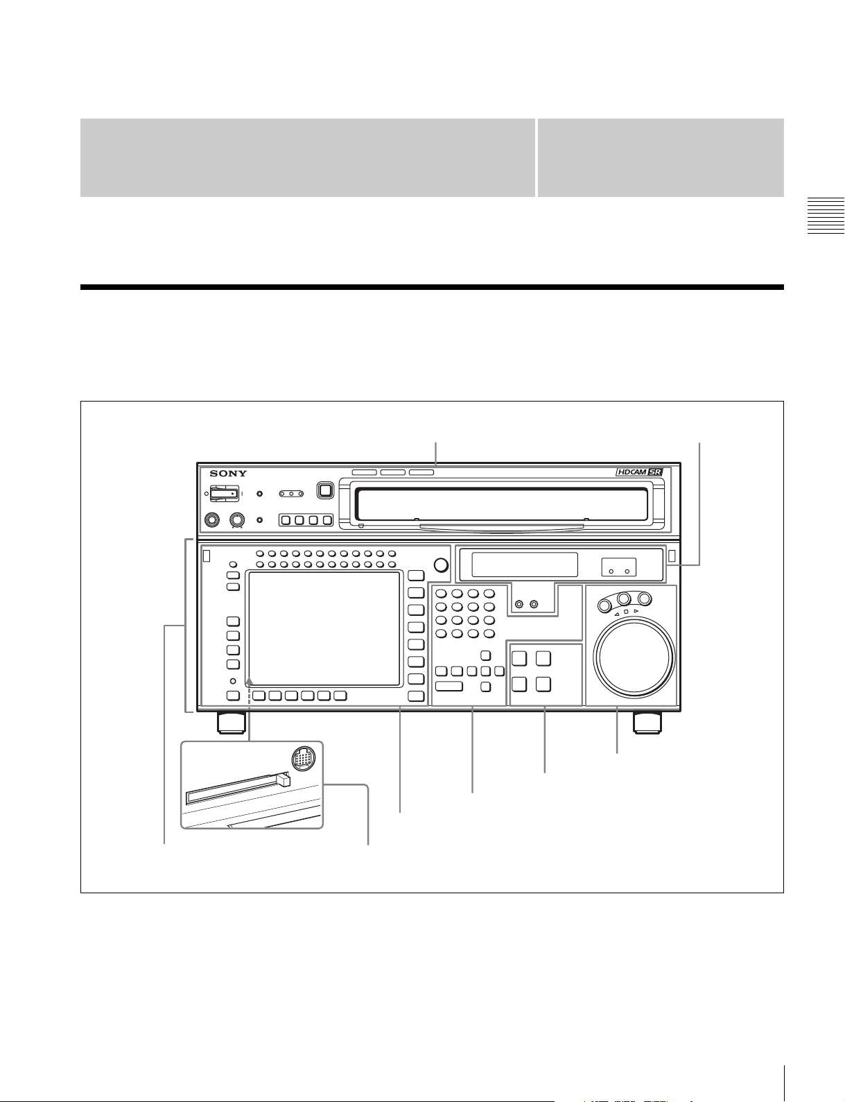
2-1 Control Panel
The control panel consists of the following sections:
• Upper control panel
• Lower control panel
• System set-up panel
Upper control panel
Chapter
2
4 Display section
(see page 20)
Chapter 2 Locations and Functions of Parts
Lower control panel
5 Search control section
(see page 21)
3 Tape transport control section (see page 19)
2 Editing control section (see page 19)
1 Menu control section (see page 17)
System set-up panel: Access by opening the lower control panel (see page 22)
2-1 Control Panel
15

2-1-1 Upper Control Panel
1 POWER switch
2 WARNING indicator
3 ERROR indicator
Chapter 2 Locations and Functions of Parts
4 CHANNEL CONDITION indicators
5 EJECT button
6 Format indicators
7 REMOTE buttons
8 PHONES level control
9 PHONES jack
a POWER switch
Pressing on the ‘(’ side of this switch powers the unit and
lights up the information display (see page 20) and color
display (see page 17). To turn the unit off, press on the ‘a’
side of the switch.
b WARNING indicator
This lights when there is a fault in the unit. You can check
the details on the lower control panel.
For details, see “Error Messages and Warning Messages”
on page 104.
c ERROR indicator
This lights when a serious problem occurs, such as an
operational malfunction or system internal error.
You can check the details on the lower control panel.
For details, see “Error Messages and Warning Messages”
on page 104.
d CHANNEL CONDITION indicators
These show the status of the playback signal.
Blue: The playback signal status is satisfactory.
Yellow: The playback signal is somewhat degraded, but
playback is possible.
However, if this indicator remains lit continuously,
head cleaning is required.
Red: The playback signal has deteriorated.
If this indicator remains lit continuously, head
cleaning or internal inspection is required.
Cassette compartment
e EJECT button
Pressing this button automatically ejects the cassette after
several seconds.
f Format indicators (Digital BETACAM/HDCAM/
HDCAM SR)
These show the format of the cassette loaded into the unit.
g REMOTE buttons
Press one of the following buttons, to select how this unit
is controlled.
NETWORK: This button lights when pressed, enabling
access from the network connected to the
NETWORK connector on this unit.
i.LINK: Reserved.
1(9P): This button lights when pressed, enabling this unit
to be controlled from a device connected to the
REMOTE 1-IN(9P) connector or REMOTE 1-I/
O(9P) connector.
2(50P): This button lights when pressed, enabling this unit
to be controlled from a device connected to the
REMOTE 2 PARALLEL I/O(50P) connector.
Note
When this unit is being controlled by the external
equipment connected to the REMOTE 1-IN(9P) or
REMOTE 2 PARALLEL I/O(50P) connector, all tape
transport buttons and edit operation buttons are disabled,
except the STOP and EJECT buttons. You may also
specify the disabling or enabling of all buttons by setting
the VTR SETUP menu item 008 “LOCAL FUNCTION
ENABLE”.
16
2-1 Control Panel
h PHONES level control
Adjusts the output level to the PHONES jack.
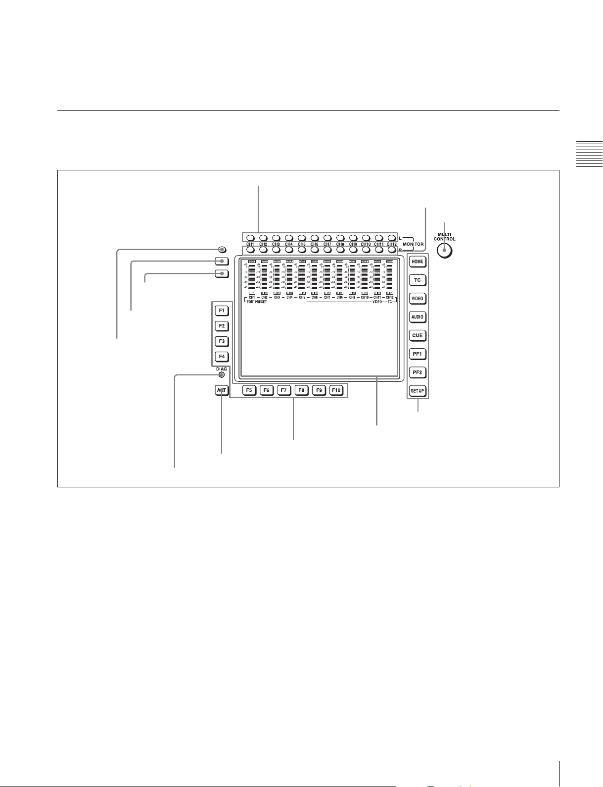
2-1-2 Lower Control Panel
1 Menu control section
9 DISPLAY button
0 FULL/FINE button
i PHONES jack
Connect stereo headphones for audio monitoring during
playback. Adjust the headphone output level with the
PHONES level control.
Chapter 2 Locations and Functions of Parts
1 MONITOR L buttons
2 MONITOR R buttons
3 MULTI CONTROL knob
qa PB LEVEL button
6 Function buttons
7 ALT button
8 DIAG button
a MONITOR L buttons
Select the audio signal output from the MONITOR
OUTPUT L connector. This assigns the desired channel to
the MONITOR OUTPUT L connector. If you assign more
than one channel to the same monitor output connector, a
mixed audio signal is output.
You can also make this setting using the VTR SETUP
menu item 807 “AUDIO MONITOR-L select”.
In the audio playback level adjustment mode, this is used
to select the channel to be adjusted.
b MONITOR R buttons
Select the audio signal output from the MONITOR
OUTPUT R connector. This assigns the desired channel to
the MONITOR OUTPUT R connector. If you assign more
than one channel to the same monitor output connector, a
mixed audio signal is output.
You can also make this setting using the VTR SETUP
menu item 808 “AUDIO MONITOR-R select”.
4 Menu selection buttons
5 Color display
In the audio playback level adjustment mode, this is used
to select the channel to be adjusted.
c MULTI CONTROL knob
Used to set the audio playback level and make settings in
the SET UP menu (see page 87).
d Menu selection buttons
These select the menu screen displayed on the display.
HOME button: Press this to go to the HOME menu
screen. The home menu provides settings for the basic
operations.
TC button: Press this to go to the TC (time code) menu
screen. In the time code menu, you can switch LTC/
VITC, switch DF/NDF, set the time code to be
displayed on an external monitor, and so on.
VIDEO button: Press this to go to the VIDEO menu
screen. Use it to make video related settings.
2-1 Control Panel
17

AUDIO button: Press this to go to the AUDIO menu
screen. Use it to make audio related settings.
CUE button: Press this to go to the CUE menu screen.
The cue menu provides 10 pages to set cue points.
You can set up to 10 cue points per page. You can also
make settings for the Tele-File memory label system.
PF1 button: Press this to go to the PF1 (personal function
1) menu screen. You can register frequently-used
items in the PF1 menu. The factory default setting is
blank.
PF2 button: Press this to go to the PF2 (personal function
Chapter 2 Locations and Functions of Parts
2) menu screen. You can register frequently-used
items in the PF2 menu. The factory default setting is
blank.
SET UP button: Press this to go to the SET UP menu
screen. The setup menu provides functions to save
menu settings in VTR banks or save to a “Memory
Stick,” registration operations in the PF buttons, VTR
SETUP menu settings, and so on.
For details of menus, see Chapter 4 “Menu Settings” on
page 34.
e Color display
This comprises principally the audio level display and
menu display.
Audio Level display:
This displays the playback levels.
The display mode can be changed with the FULL/FINE
button. The factory default display is a reference level of
–20 dB, and peak level 0 dB.
Menu display:
This displays the menu screen selected by the menu
selection buttons.
Each menu screen shows the functions assigned to the
function buttons ([F1] to [F10]), and shows simultaneously
information required for time code display settings and so
on.
Note on faulty pixels on the LCD panel
The LCD panel fitted to this unit is manufactured with
high precision technology, giving a functioning pixel
ratio of at least 99.99%. Thus a very small proportion of
pixels maybe “stuck”, either always off (black), always
on (red, green, or blue), or flashing. In addition, over a
long period of use, because of the physical characteristics
of the liquid crystal display, such “stuck” pixels may
appear spontaneously. These problems are not a
malfunction. Note that any such problems have no effect
on recorded data.
h DIAG (diagnostic) button
Hold down the SFT button (see page 19) in the editing
control section and press this switch to switch to the DIAG
menu.
i DISPLAY button
This displays the down-converted output signal in the
whole color display.
Notes
• Depending on the system settings, it may not be possible
to output some signals.
• This function is for a quick check of the output signal,
and cannot be used as a monitor.
j FULL/FINE button
This selects the audio level meter display range.
FULL: The audio level meter display is from –60 dB to 0
dB, or –40 dB to +20 dB. Select which of these ranges
(peak level: 0 dB or +20 dB) is displayed in the VTR
SETUP menu item 814 “LEVEL METER SCALE”.
FINE: The audio level meter display range is expanded,
and displayed with a scale in steps of 0.25 dB. The
reference marker LED at the center of the level meter
display range lights. When the audio level exceeds the
maximum display range, the top OVER display
flashes. When under the minimum display range, the
bottom line flashes.
k PB (playback) LEVEL button
Press this button to enter the playback audio level
adjustment mode. In this mode, you can use the
MONITOR R button to select the adjustment target
channels from channels 1 to 12. While watching the audio
level meter, turn the MULTI CONTROL knob for a
desired audio level.
Clicking the MULTI CONTROL knob resets the playback
audio level to the factory set level (a reference level of –20
dB is set for a +4 dBm input). Clicking the MULTI
CONTROL knob again restores the adjusted level.
Press this button again to exit from the playback audio
level adjustment mode, and the MONITOR L and R
buttons return to the normal status (this status is called the
“MONITOR SELECT mode”).
f Function buttons
Activates the functions in each menu.
g ALT (alternative) button
Press to change the items displayed on the current menu.
Press again to return to the original items.
18
2-1 Control Panel
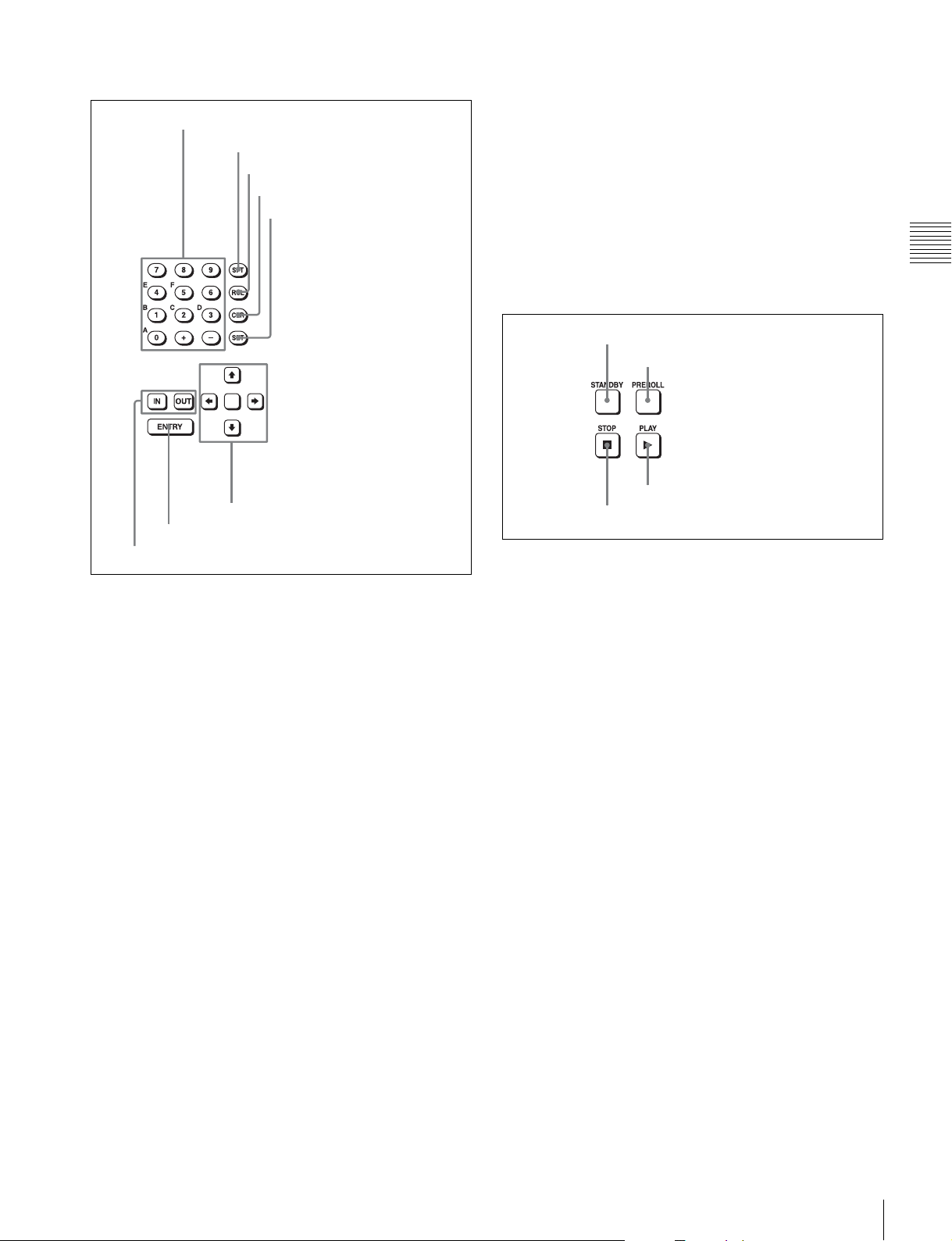
2 Editing control section
While holding down this button, press either the IN or
OUT button.
1 Numeric buttons and +/– buttons
2 SFT button
3 RCL button
4 CLR button
5 SET button
6 Cursor buttons
7 ENTRY button
8 IN/OUT buttons
a Numeric buttons and +/– buttons
Press to input time data or edit points data at the cursor
position in menu display. Press buttons 0 to 5 while
holding down the SFT button to input hexadecimal A to F
for user bits. Use the +/– buttons to increase or decrease
settings.
b SFT (shift) button
Press buttons 0 to 5 while holding down this button to
input hexadecimal A to F for user bits.
Use also in combination with other buttons to perform
other operations.
c RCL (recall) button
Press to recall the previous setting, etc.
h IN/OUT buttons
To set a IN or OUT point during editing, press either of
these buttons while holding down the ENTRY button.
While editing by connecting this unit to a recorder, press
the IN or OUT button while holding down the SFT button
and the CLR button to delete the AUDIO IN or AUDIO
OUT point that is set by an external device.
Chapter 2 Locations and Functions of Parts
3 Tape transport control section
1 STANDBY button
2 PREROLL button
5 PLAY button
6 STOP button
a STANDBY button
Press this button in other than standby mode to make it
light up and place this unit in standby mode. The head
drum rotates in standby mode, thereby shortening the time
required for the tape to start.
Press this button while in standby mode to turn the button
off and exit from standby mode. The head drum stops
rotating and the tape tension is released. If this unit
remains in standby mode for more than eight minutes
(factory setting), standby mode is automatically canceled
in order to safeguard the tape.
b PREROLL button
Press to run the tape to the preroll point (a position factory
set to five seconds before the IN point).
Press this button while holding down the IN or OUT button
to cue up the tape at the IN or OUT point.
d CLR (clear) button
Press to clear input data.
e SET button
Press to finalize input data.
f Cursor buttons
Use to move the cursor (shown in reverse video) on the
display. Also use to change menu settings.
g ENTRY button
Press to enter an edit or cue point.
For details on changing the preroll time, see “4-2-3
Setting the Preroll Time (PREROLL TIME)” on page 49.
c PLAY button
Press to start playback.
d STOP button
Press this button to stop playback.
When you insert the cassette, this unit automatically enters
STBY OFF mode.
The STOP button flashes in the following cases.
• There is no external reference video signal.
2-1 Control Panel
19
• This unit is out of synchronization with the external
reference video signal.
You can change the setting of the VTR SETUP menu item
102 “REFERENCE SYSTEM ALARM” so that the STOP
button will not flash in these cases.
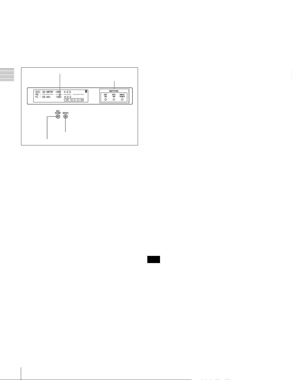
4 Display section
1 Information display
Chapter 2 Locations and Functions of Parts
3 SERVO indicator
4 REC INHIBIT indicator
a Information display
The information display shows a number of different
pages. To change the page displayed, with no other items
selected in the menu display (HOME, TC, VIDEO,
AUDIO, PF1, and PF2), turn the MULTI CONTROL knob
while holding it down.
The currently selected page number also appears at the
upper right of the information display.
Page 1: System status
SYS: Shows the system information (signal standard and
tape format).
PB: Shows the information recorded on the tape (signal
standard and tape format) while being played back.
FC: Shows the converted signal standard when an HKSR-
5001 board is installed.
TC: Shows the time code.
Page 2: System status
ACTIVE LINE: Shows the status of 1080/1035
conversion active line.
1080t1080
1035t1080(PANEL)
1035t1080(CONV): Shows the current conversion
status.
- - - - -: Cannot be converted.
OFF: No conversion done.
DOWN CONV. OUTPUT: Shows the output status of the
down converter.
ACTIVE: Output.
MUTING: No output.
EOS: Appears at the location of the time code for the valid
end of the previous recording.
2 REF SYNC indicators
Page 3: Phase (OUTPUT)
HD SDI OUTPUT ADV.: Shows the phase of the main
line HD SDI output.
OFF: In phase with reference.
–90H: 90H (HD) advanced with respect to reference.
DOWN CONV. OUTPUT ADV.: Shows the phase of the
down converter output.
OFF: In phase with reference.
–2H: 2H (SD) advanced with respect to reference.
Page 4: Phase (AUDIO)
AUDIO PB OUTPUT ADV.: Shows the phase of the
audio output signal.
OFF: Output in phase with the video output signal.
–1Frame: Output one frame advanced with respect to
the video output signal.
AES/EBU & MONITOR OUTPUT: Shows the phase of
the AES/EBU and MONITOR AUDIO outputs.
REF: Output in phase with reference.
FC: In phase with the FC output.
–90H(HD): 90H (HD) advanced with respect to
reference.
–2H(SD): 2H (SD) advanced with respect to
reference.
Page 5: Phase (TC)
LTC OUTPUT: Shows the phase of the output LTC.
LINE: Output in phase with the main line HD SDI
output.
FC: Output in phase with the FC output.
Page 6: Meta Data
META DATA LINE(OUT): Shows the status of the three
lines of main HD SDI output into which metadata is
multiplexed.
META DATA LINE(FC): Shows the status of the three
lines of output from the optional HKSR-5001 format
converter board into which metadata is multiplexed.
META DATA LINE(SD): Shows the status of the three
lines of SD SDI output into which metadata is
multiplexed.
Note
The ACTIVE LINE setting displayed on page 2 can be
made in the SYSTEM menu under the OTHERS CHECK
menu in the MAINTENANCE menu. The phase settings
displayed on pages 3 to 5 and the settings relating to meta
data displayed on page 6 can be made in the PHASE SET/
META DATA menu under the ALT+OTHERS CHECK
menu in the MAINTENANCE menu.
For details, refer to the Installation Manual.
b REF SYNC (reference signal) indicators
These indicate the signal selected as the reference signal.
If there is no reference signal input to the selected
connector, the STOP button flashes.
20
2-1 Control Panel
EXT SD: Lights when “extern SD” is selected by the VTR
SETUP menu item 006 “EXTERNAL REFERENCE
select”.
EXT HD: Lights when “extern HD” is selected by the
VTR SETUP menu item 006 “EXTERNAL
REFERENCE select”.
c SERVO indicator
Lights up when the drum servo and capstan servo are
locked.
d REC INHIBIT indicator
Only when this indicator is not lit, you can record or erase
the stop code.
The status of this indicator depends on the setting of the
VTR SETUP menu item 010 “STOP CODE INHIBIT
select” and the state of the record-protect plug on the
cassette.
Setting of the VTR
SETUP menu item
010
on Recording disabled
off Recording disabled
a) Toggling between lit/flashing settings is possible using the VTR SETUP
menu item 104 “REC INHIBIT LAMP FLASHING”.
State of the recordprotect plug on the
REC INHIBIT
indicator
cassette
Lit/flashing
Recording allowed Lit
Lit/flashing
Recording allowed
Unlit
a)
a)
a)
picture) and ±10 times normal playback speed (HDCAM/
Digital Betacam) or ±8 times normal playback speed
(HDCAM-SR).
Frame frequency
Playback speed range (for
HDCAM-SR format)
23.98/24 Hz ±50 times normal playback speed
25 Hz ±48 times normal playback speed
29.97/30 Hz ±40 times normal playback speed
50 Hz ±24 times normal playback speed
59.94/60 Hz ±20 times normal playback speed
b JOG button
Press to select jog mode. In this mode, the button lights up
and playback is possible at –1 to +1 times normal speed, ±2
times normal speed (HDCAM/HDCAM-SR), or ±3 times
normal speed (Digital Betacam) (determined by the setting
in the VTR SETUP menu item 107 “JOG DIAL
RESPONSE”). In this mode, the search dial does not click.
c VAR (variable) button
Press to select variable speed playback mode for noiseless
playback in the range from –0.5 to +1 times normal speed
(HDCAM-SR), from –1 to +2 times normal speed
(HDCAM), or from –1 to +3 times normal speed (Digital
Betacam). Playback exceeding this speed range is not
possible. The search dial clicks at the positions for stillpicture and normal playback speed.
Chapter 2 Locations and Functions of Parts
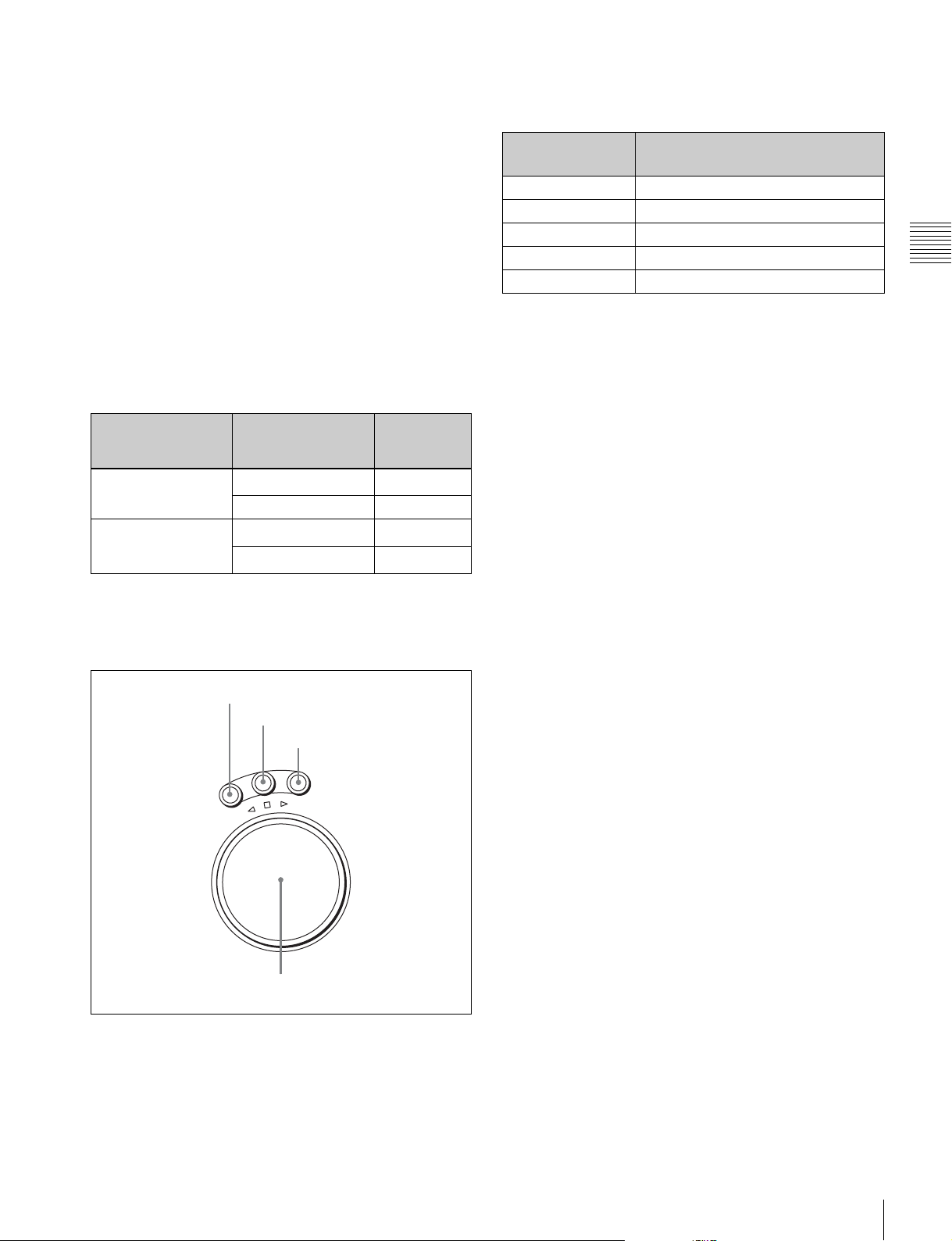
5 Search control section
1 SHUTTLE button
2 JOG button
3 VAR button
V
G
A
O
J
E
L
T
T
U
H
S
E
S
R
E
V
E
R
a SHUTTLE button
Press to enter shuttle mode. In this mode, the button lights
and playback at the speed corresponding to the angle of
rotation of the search dial is possible. The playback speed
range depends on the frame frequency of the unit. In this
mode, the search dial clicks at the positions for 0 (still
R
F
O
R
W
A
R
D
4 Search dial
d Search dial
Rotate to search for edit points. Rotate the dial clockwise
for forward playback (the B indicator lights up) or
counterclockwise for reverse playback (the b indicator
lights up). The x indicator lights up while this unit is in
stop mode.
Shuttle mode: The playback speed corresponds to the
angle of rotation of the search dial. The playback
speed range depends on the frame frequency of the
unit. (See item 1 SHUTTLE button.) The dial clicks
at the positions for 0 (still picture) and ±10 times
normal playback speed (HDCAM/Digital Betacam)
or ±8 times normal playback speed (HDCAM-SR).
Jog mode: The playback speed corresponds to the
rotational speed of the dial (–1 to +1 times normal
speed, ±2 times normal speed (HDCAM/HDCAMSR), or ±3 times normal speed (Digital Betacam))
depending on the setting of the VTR SETUP menu
item 107 “JOG DIAL RESPONSE”). The dial does
not click.
Variable speed playback mode: Noiseless playback is
possible in the range from –0.5 to +1 times normal
speed (HDCAM-SR), from –1 to +2 times normal
speed (HDCAM), or from –1 to +3 times normal
speed (Digital Betacam). The speed settings can be
changed using the menu. The dial clicks at the
positions for still-picture and normal playback speed.
2-1 Control Panel
21
Capstan override mode: Rotating the dial while holding
down the PLAY button changes the playback speed
by up to ±15%.
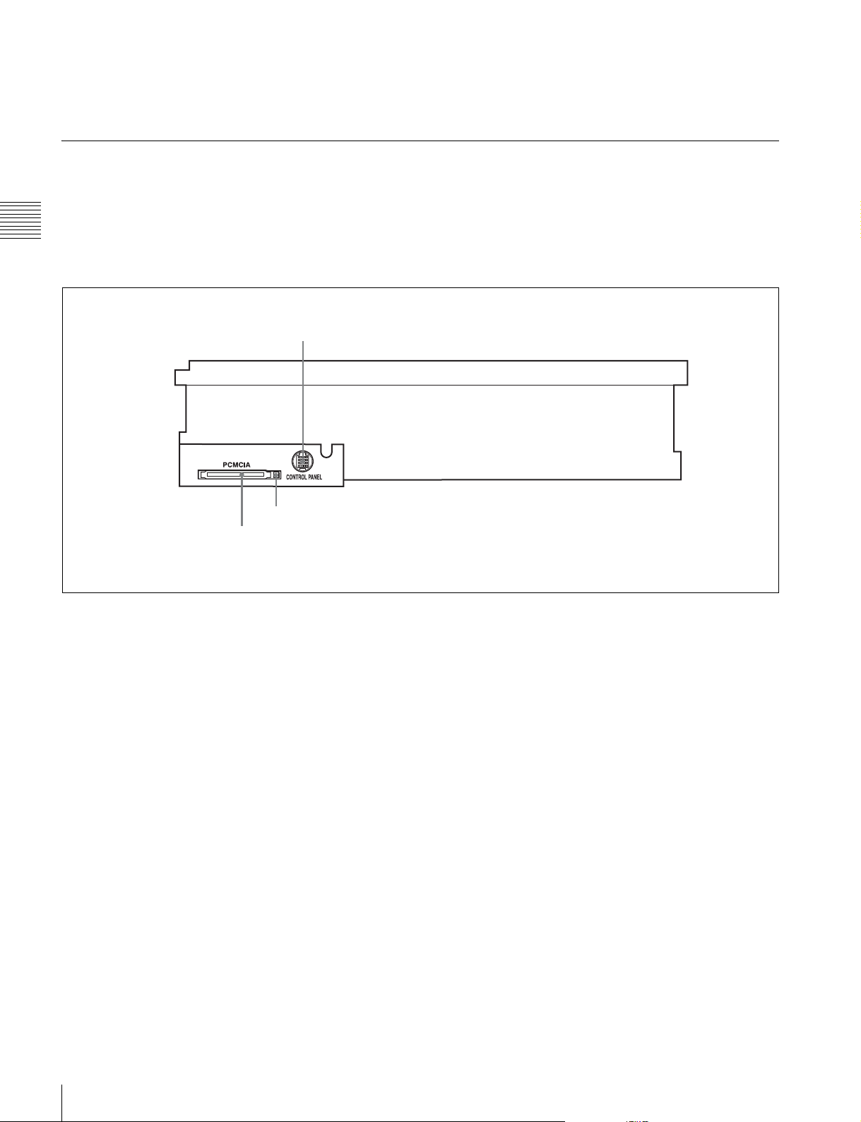
2-1-3 System Set-Up Panel
Lift the lower control panel up to its horizontal position to
access the system set-up panel.
Chapter 2 Locations and Functions of Parts
For details of opening and closing the control panel, refer
to the Maintenance Manual.
CONTROL PANEL connector
Card slot eject button
PCMCIA card slot
For details, see “3-4 Using a “Memory Stick”” on
page 32.
22
2-1 Control Panel
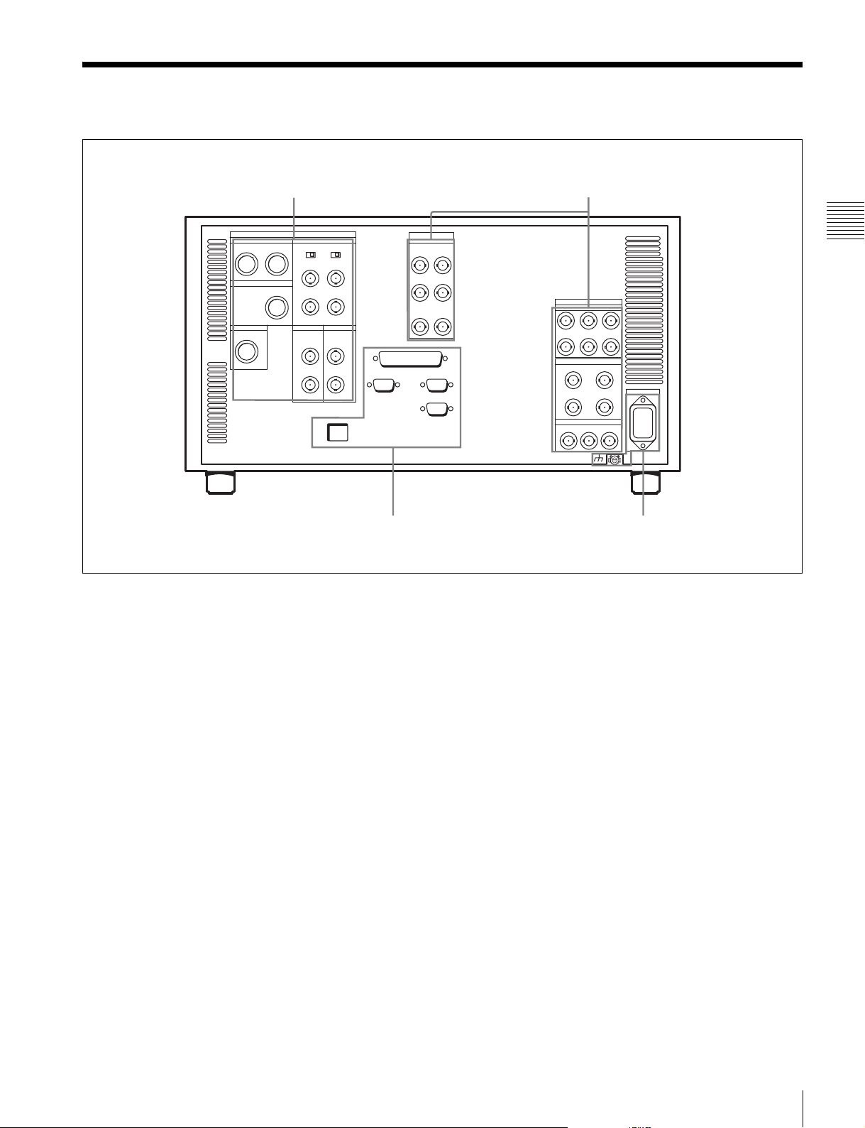
2-2 Connector Panel
1 ANALOG I/O section (see page 24)
3 Remote input/output section
(see page 26)
2 DIGITAL I/O section (see page 25)
Chapter 2 Locations and Functions of Parts
4 Power supply
(see page 26)
2-2 Connector Panel
23
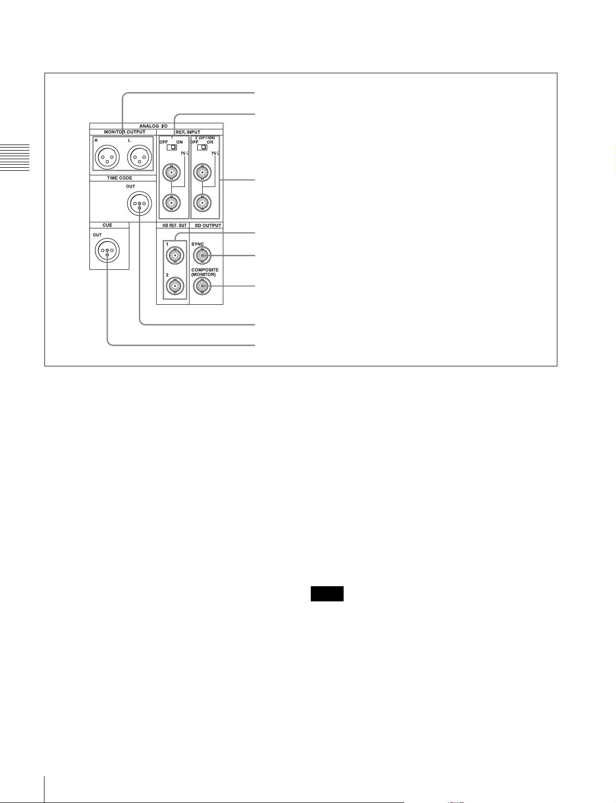
1 ANALOG I/O (input/output) section
2 REF. INPUT 1 connectors and 75Ω termination switch
1 MONITOR OUTPUT L/R connectors
Chapter 2 Locations and Functions of Parts
a MONITOR OUTPUT L/R connectors
(XLR-3-31, male)
These output the audio signals for monitoring L and R
channels. To select the signals to output, use the
MONITOR L and MONITOR R buttons on the lower
control panel.
For details, see “5-1-2 Selecting Audio Signals To Be
Monitored” on page 92.
b REF. (reference video) INPUT 1 connectors (BNC)
and 75Ω termination switch
Input a reference video signal of the selected field
frequency. Select HD or SD with the VTR SETUP menu
item 006 “EXTERNAL REFERENCE select”. When HD
is selected, input a tri-level SYNC signal. When SD is
selected, input a video signal with chroma burst (VBS) or
a monochrome video signal (VS).
A loop-through connection is possible. Set the 75Ω
termination switch to OFF if you are using a loop-through
connection and set it to ON if you are not using a loopthrough connection.
3 REF. INPUT 2 connectors and 75Ω termination switch
4 HD REF. OUT connectors
5 SD OUTPUT SYNC connector
6 SD OUTPUT COMPOSITE (MONITOR) connector
7 TIME CODE OUT connector
8 CUE OUT connector
c REF. (reference video) INPUT 2 connectors (BNC)
and 75Ω termination switch
Input a reference video signal of the field frequency
selected for the format converter output. Select HD or SD
with the VTR SETUP menu item A08 “FC REFERENCE
select”. When HD is selected, input an HD tri-level SYNC
signal for external synchronization. When SD is selected,
input a video signal with chroma burst (VBS) or a
monochrome video signal (VS). A loop-through
connection is possible. Set the 75Ω termination switch to
OFF if you are using a loop-through connection and set it
to ON if you are not using a loop-through connection.
d HD REF. OUT (sync signal output) connectors
(BNC)
Output an HD tri-level sync signal during tape playback.
Notes
• When the system is operated in 4:2:2/720P mode, no
signal is output from these connectors.
• When the system is operated in 4:2:2/1080/50P, 4:2:2/
1080/59.94P, or 4:2:2/1080/60P mode, the reference
signal that is identical to interlace signal is output from
these connectors.
24
2-2 Connector Panel
e SD OUTPUT SYNC connector (BNC)
This outputs an NTSC or PAL signal for external
synchronization.
Note
The output phase is the same as that of the composite
signal output from the SD OUTPUT COMPOSITE
(MONITOR) connector.
Because the output phase changes with the operation mode
of this unit, use this for synchronization with the video
monitor.
g TIME CODE OUT (time code output) connector
(XLR 3-31, male)
Outputs the playback time codes.
h CUE OUT (cue output) connector
(XLR 3-31, male)
Outputs cue track audio during HDCAM or Digital
Betacam playback.
f SD OUTPUT COMPOSITE (MONITOR)
connector (BNC)
Outputs an analog composite signal for a video monitor.
When the ALT/[F6] (CHARA SUPER) setting in the TC
menu is on, character signals such as time codes are
superimposed on the output.
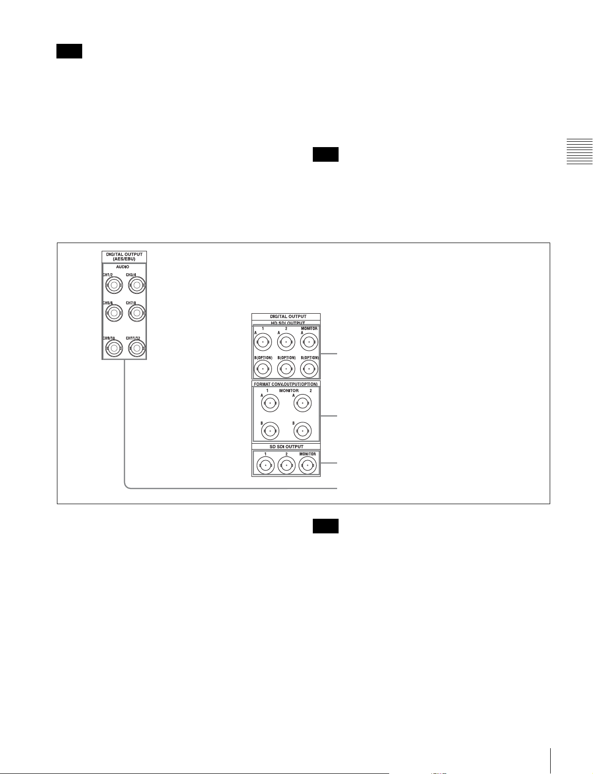
2 DIGITAL I/O (input/output) section
Note
Chapter 2 Locations and Functions of Parts
There is no cue track on an HDCAM-SR tape, and
therefore no output.
1 HD SDI OUTPUT A/B connectors
2 FORMAT CONV. OUTPUT (OPTION) A/B connectors
a HD SDI (SDI video/audio) OUTPUT A/B
connectors (BNC)
These output three sets of SDI video/audio signals.
When the ALT/[F6] (CHARA SUPER) buttons are set to
ON in the TC menu, time data or other text data is
superimposed on the signal output from the MONITOR
connector.
b FORMAT CONV. (format-converted video/audio)
OUTPUT (OPTION) A/B connectors (BNC)
These output two sets of format-converted video/audio
signals.
When the ALT/[F5] (FC CHARA) buttons are set to ON in
the TC menu, the output has time data or other text
superimposed on the signal.
3 SD SDI OUTPUT 1/2/MONITOR connectors
4 DIGITAL OUTPUT (AES/EBU) AUDIO connectors
Note
This is only valid when the optional HKSR-5001 format
converter board is installed.
c SD SDI OUTPUT 1/2/MONITOR connectors
(BNC)
These output three sets of video/audio signals. When the
ALT/[F6] (CHARA SUPER) buttons are set to ON in the
TC menu, time data or other text data is superimposed on
the output from the MONITOR connector.
d DIGITAL OUTPUT (AES/EBU) AUDIO
connectors (BNC)
These output digital audio signals in AES/EBU format for
channels 1 to 12.
2-2 Connector Panel
25
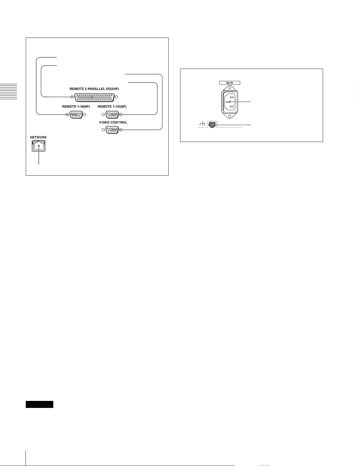
3 Remote input/output section
• When you connect the NETWORK cable of the unit to
peripheral device, use a shielded-type cable to prevent
malfunction due to radiation noise.
1 REMOTE1-IN(9P) connector
2 REMOTE 2 PARALLEL I/O(50P) connector
3 VIDEO CONTROL connector
4 REMOTE1-I/O(9P) connector
Chapter 2 Locations and Functions of Parts
5 NETWORK connector
a REMOTE 1-IN(9P) connector (D-sub 9-pin,
female)
Use this, with the supplied 9-pin remote control cable, to
connect the unit to a recorder (e.g., SRW-5800) or an HD
VTR unit to carry out editing with a BVE-series editor
BVE-900/910/2000/9000/9100.
4 Power supply
1 AC IN connector
2 U Ground terminal
a AC IN connector
Connects to an AC outlet using an appropriate power cord.
b U Ground terminal
b REMOTE 2 PARALLEL I/O(50P) connector (D-
sub 50-pin, female)
Inputs an external remote control signal.
For details, refer to the Maintenance Manual Volume 1.
c VIDEO CONTROL (Digital Video Processor
Control) connector (D-sub 9-pin, female)
Connects to the optional HKDV-900 HD Digital Video
Controller to enable remote control of the internal digital
video processor. Turn off the power before connecting the
remote controller.
d REMOTE 1-I/O(9P) connector (D-sub 9-pin,
female)
Use this, with the supplied 9-pin remote control cable, to
connect the unit to a recorder (e.g., SRW-5800) or an HD
VTR unit to carry out editing with a BVE-series editor
BVE-700/2000/9000/9100.
e NETWORK connector
Used for monitoring this unit by SNMP, or for setting or
changing settings of this unit by HTTP.
CAUTION
• For safety, do not connect the connector for peripheral
device wiring that might have excessive voltage to this
port. Follow the instructions for this port.
26
2-2 Connector Panel
Setting Up the Unit
Chapter
3
3-1 Connecting External Equipment
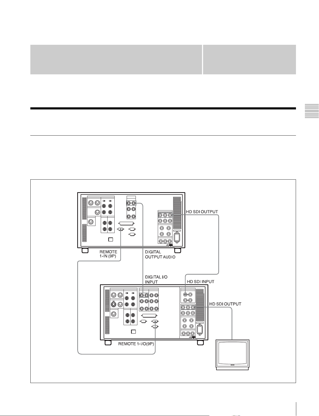
3-1-1 Making HD Digital Connections
This example shows the connections when using an SRW5100 as player and an SRW-5800 as recorder, in 59.94i or
60i mode.
SRW-5100 (Player)
9-pin remote control cable
For details on operation and settings of automatic editing,
refer to the Operation Manual supplied with the SRW-
5800.
Chapter 3 Setting Up the Unit
SRW-5800 (Recorder)
Video monitor
(HD serial monitor)
3-1 Connecting External Equipment
27
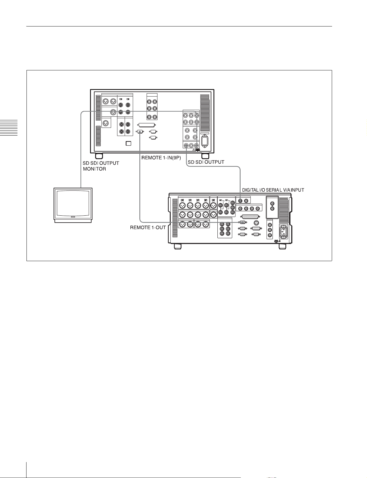
3-1-2 Making NTSC/PAL Digital Connections
This example shows how to connect two units, an SRW5100 as the player and a DVW-2000 D-1 Component
Digital VTR as the recorder.
SRW-5100 (Player)
Chapter 3 Setting Up the Unit
BNC cable
Video monitor
(NTSC/PAL monitor)
BNC cable
DVW-2000 (Recorder)
9-pin remote
control cable
28
3-1 Connecting External Equipment
3-2 Reference Signals
This section describes how reference signals for the video
output are selected.
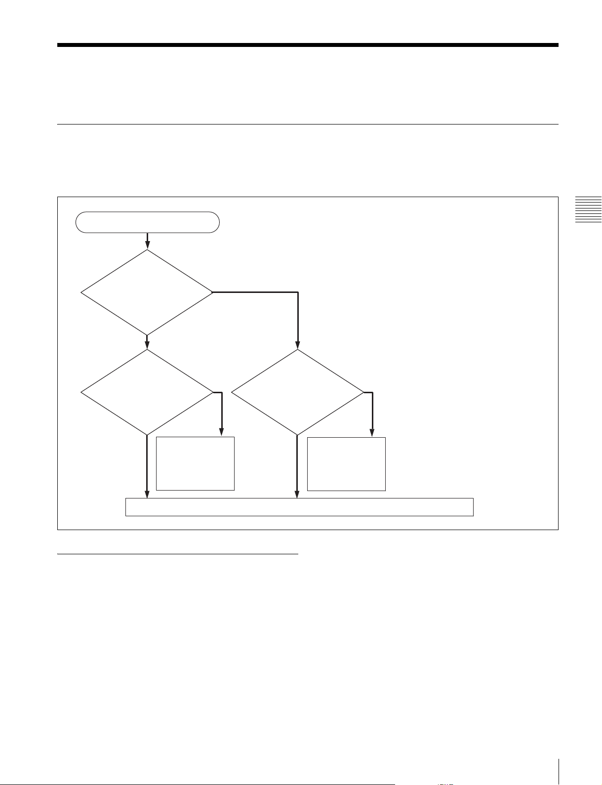
3-2-1 Reference Signals for Output Video
Depending on the operating condition, VTR SETUP menu
settings, the input signal, and the video output signal from
this unit can be synchronized as follows.
Start
What is the setting
of the VTR SETUP
menu item 006
“EXTERNAL
REFERENCE
select”?
extrn HD
Is there a signal of the
correct frequency on
the REF. INPUT 1 or
a)
connector?
2
No
Synchronization
with the reference
video signal input to
the REF. INPUT 1
a)
or 2
a) The signal on the REF. INPUT 2 connector is the signal for FORMAT CONV.
output. Use the “A08: FC REFERENCE select” menu item to switch between
HD and SD for the signal input to the REF. INPUT 2 connector.
extrn SD
Yes
connector
No external synchronization (synchronization is internal)
Is there a signal of the
correct frequency on
the REF. INPUT 1 or
a)
connector?
2
No
Synchronization
with the video signal
input to the REF.
INPUT 1 or 2
connector
Yes
a)
Chapter 3 Setting Up the Unit
3-2-2 Reference Signal Connections
Make the reference signal connection as follows,
according to your playback requirements.
3-2 Reference Signals
29
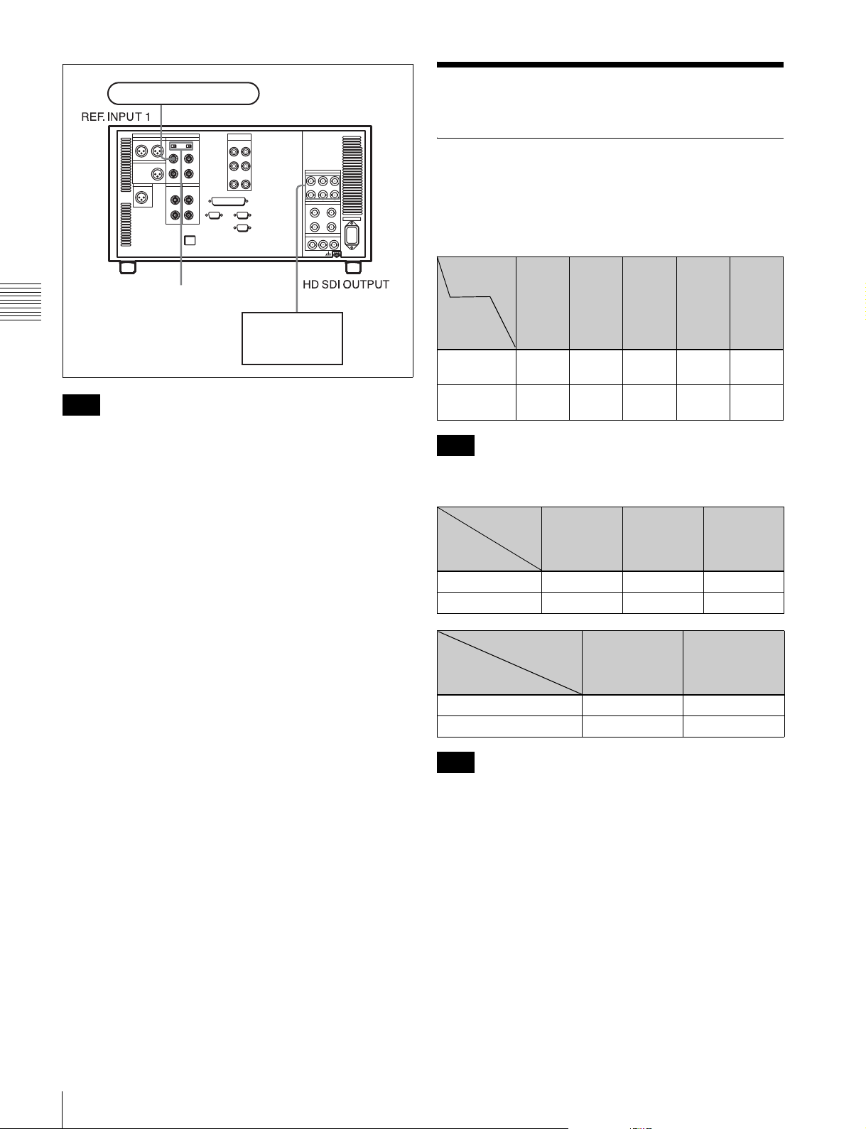
Reference signal
SRW-5100
75Ω termination switch: ON
Chapter 3 Setting Up the Unit
Note
HD serial input
monitor
The following signals can be used as a reference signal.
• HD trilevel SYNC signal of an appropriate field
frequency for external synchronization
• Black burst signal of 525/59.94 Hz
• Black burst signal of 625/50 Hz
Input the signal of the appropriate field frequency for your
system.
Sync signals in 720p mode
Synchronize to an external sync signal when you want to
play back 720p signals on this unit (including editing).
• When the 720/59.94p system is selected:
You can select the following reference signals from
menu item 006 “EXTERNAL REFERENCE select”.
extrn HD: 1080/59.94i tri-level SYNC signal
extrn SD: 525 black burst signal
• When the 720/50p system is selected:
You can select the following reference signals from
menu item 006 “EXTERNAL REFERENCE select”.
extrn HD: 1080/50i tri-level SYNC signal
extrn SD: 625 black burst signal
3-3 Handling Cassettes
3-3-1 Recommended Cassettes
Use 1/2 inch HDCAM-SR, HDCAM, or Digital Betacam
cassettes.
The maximum playback time is as shown in the following
tables.
System
frequency
HDCAM
SRcassette
S-size
cassette
L-size
cassette
Note
The playback time for RGB (4:4:4) HQ mode is one-half
those indicated in the table above.
System
frequency
HDCAM
cassette
S-size cassette 40 minutes 48 minutes 50 minutes
L-size cassette 124 minutes 149 minutes 155 minutes
Digital
Betacam cassette
S-size cassette 40 minutes 40 minutes
L-size cassette 124 minutes 124 minutes
Note
Playing back a Digital Betacam or HDCAM cassette
requires the optional HKSR-5802 Digital Betacam/
HDCAM Processor Board.
59.94/
60 Hz
20
minutes
62
minutes
System
frequency
50 Hz
24
minutes
74
minutes
29.97/30 Hz 25 Hz 23.98/24 Hz
29.97/
30 Hz
40
minutes
124
minutes
29.97 Hz 25 Hz
25 Hz
48
minutes
149
minutes
23.98/
24 Hz
50
minutes
155
minutes
30
3-3 Handling Cassettes
Storage of cassettes
Store your cassettes at room temperature and normal
humidity.
 Loading...