

Sony SRW-5001, SRW-5003, SRW-5002, SRW-5000 Operation Manual

HD DIGITAL VIDEOCASSETTE RECORDER
SRW-5000
FORMAT CONVERTER BOARD
HKSR-5001
DIGITAL BETACAM PROCESSOR BOARD
HKSR-5002
RGB PROCESSOR BOARD
HKSR-5003
Note
The supplied CD-ROM includes operation manuals for the SRW-5000 series of
digital camcorders (English, Japanese, French and German versions).
For more details, see page 1-6 “Using the CD-ROM Manual.”
OPERATION MANUAL
[English]
1st Edition
Serial No. 10101 and Higher

WARNING
To prevent fire or shock hazard, do not
expose the unit to rain or moisture.
To avoid electrical shock, do not open the
cabinet. Refer servicing to qualified
personnel only.
THIS APPARATUS MUST BE EARTHED.
AVERTISSEMENT
Afin d’éviter tout risque d’incendie ou
d’électrocution, ne pas exposer cet
appareil à la pluie ou à l’humidité.
This symbol is intended to alert the user to the
presence of uninsulated “dangerous voltage”
within the product’s enclosure that may be of
sufficient magnitude to constitute a risk of
electric shock to persons.
Afin d’écarter tour risque d’électrocution,
garder le coffret fermé. Ne confier
l’entretien de l’appareil qu’à un personnel
qualifié.
CET APPAREIL DOIT ÊTRE RELIÉ À LA
TERRE.
VORSICHT
Um Feuergefahr und die Gefahr eines
elektrischen Schlages zu vermeiden, darf
das Gerät weder Regen noch Feuchtigkeit
ausgesetzt werden.
Um einen elektrischen Schlag zu
vermeiden, darf das Gehäuse nicht
geöffnet werden. Überlassen Sie
Wartungsarbeiten stets nur qualifiziertem
Fachpersonal.
This symbol is intended to alert the user to the
presence of important operating and
maintenance (servicing) instructions in the
literature accompanying the appliance.
DIESES GERÄT MUSS GEERDET
WERDEN.

Important Safety Instructions
WARNING: THIS WARNING IS APPLICABLE FOR
OTHER COUNTRIES.
• Read these instructions.
• Keep these instructions.
• Heed all warnings.
• Follow all instructions.
• Do not use this apparatus near water.
• Clean only with dry cloth.
• Do not block any ventilation openings.
Install in accordance with the manufacturer’s instructions.
• Do not install near any heat sources such as radiators,
heat registers, stoves, or other apparatus (including
amplifiers) that produce heat.
• Do not defeat the safety purpose of the polarized or
grounding-type plug. A polarized plug has two blades with
one wider than the other. A grounding-type plug has two
blades and a third grounding prong. The wide blade or the
third prong are provided for your safety. If the provided
plug dose not fit into your outlet, consult an electrician for
replacement of the obsolete outlet.
• Protect the power cord from being walked on or pinched
particularly at plugs, convenience receptacles, and the
point where they exit from the apparatus.
• Only use attachments/accessories specified by the
manufacturer.
• Use only with the cart, stand, tripod, bracket, or
table specified by the manufacturer, or sold with
the apparatus.
When a cart is used, use caution when moving
the cart/ apparatus combination to avoid injury
from tip-over.
• Unplug this apparatus during lightning storms or when
unused for long periods of time.
• Refer all servicing to qualified service personnel. Servicing
is required when the apparatus has been damaged in any
way, such as power-supply cord or plug is damaged, liquid
has been spilled or objects have fallen into the apparatus,
the apparatus has been exposed to rain or moisture, does
not operate normally, or has been dropped.
WARNING: THIS WARNING IS APPLICABLE FOR USA
ONLY.
If used in USA, use the UL LISTED power
cord specified below.
DO NOT USE ANY OTHER POWER CORD.
Plug Cap Parallel Blade with ground pin
(NEMA 5-15P Configuration)
Cord Type SJT, three 16 or 18 AWG
wires
Length Minimum 1.5 m, less than
2.5 m (8 ft 3 in)
Rating Minimum 10 A, 125 V
Using this unit at a voltage other than 120V
may require the use of a different line cord or
attachment plug, or both. To reduce the risk
of fire or electric shock, refer servicing to
qualified service personnel.
1. Use the approved Power Cord (3-core mains lead)/
Appliance Connector/Plug with earthing-contacts that
conforms to the safety regulations of each country if
applicable.
2. Use the Power Cord (3-core mains lead)/Appliance
Connector/Plug conforming to the proper ratings
(Voltage, Ampere).
If you have questions on the use of the above Power Cord/
Appliance Connector/Plug, please consult a qualified
service personnel.
AVERTISSEMENT: CET AVERTISSEMENT EST
VALABLE POUR LES AUTRES PAYS.
1. Utiliser un cordon d’alimentation approuvé (conducteur
d’alimentation 3 âmes)/connecteur d’appareil/prise avec
contacts de mise à la terre conforme aux règles de
sécurité de chaque pays si applicable.
2. Utiliser un cordon d’alimentation approuvé (conducteur
d’alimentation 3 âmes)/connecteur d’appareil/prise
conforme aux valeurs nominales (tension, ampérage)
correctes.
S’adresser à un personnel de service qualifié pour toute
question concernant l’emploi du cordon d’alimentation/
connecteur d’appareil/prise ci-dessus.
WARNUNG: DIESE WARNUNG GILT FÜR ANDERE
LÄNDER.
1. Verwenden Sie Netzkabel (dreiadrig), Geräteanschlüsse
und Netzkabelstecker mit Masseleitung, die den
Sicherheitsrichtlinien des jeweiligen Landes entspricht.
2. Verwenden Sie Netzkabel (dreiadrig), Geräteanschlüsse
und Netzkabelstecker mit Masseleitung, die den vor Ort
herrschenden Spannungsanforderungen (Spannug,
Stromstärke) entsprechen.
Bei Frage über die Eignung und Sicherheit von Netzkabein
(dreiadrig), Geräteanschlüssen und Netzkabelsteckern
wenden Sie sich bitte an einen qualifizierten
Electrotechniker.
CAUTION
The apparatus shall not be exposed to dripping or splashing
and no objects filled with liquid, such as vases, shall be
placed on the apparatus.
ATTENTION
Eviter d’exposer l’appareil à un égouttement ou à des
éclaboussures et ne placer aucun objet rempli de liquide,
comme un vase, sur l’appareil.
ACHTUNG
Das Gerät ist nicht tropf- und spritzwassersicher, daher
dürfen keine mit Flüssigkeiten gefüllten Gegenstände, z. B.
Vasen, darauf abgestellt werden.

CAUTION
The unit is not disconnected from the AC power source
(mains) as long as it is connected to the wall outlet, even if
the unit itself has been turned off.
ATTENTION
Cet appareil n’est pas déconnecté de la source
d’alimentation secteur tant qu’il est raccordé à la prise
murale, même si l’appareil lui-même a été mis hors tension.
ACHTUNG
Solange das Netzkabel an eine Netzsteckdose
angeschlossen ist, bleibt das Gerät auch im
ausgeschalteten Zustand mit dem Strommetz verbunden.
For the customers in U.S.A.
This equipment has been tested and found to comply with
the limits for a Class A digital device, pursuant to Part 15 of
the FCC Rules. These limits are designed to provide
reasonable protection against harmful interference when the
equipment is operated in a commercial environment. This
equipment generates, uses, and can radiate radio frequency
energy and, if not installed and used in accordance with the
instruction manual, may cause harmful interference to radio
communications. Operation of this equipment in a
residential area is likely to cause harmful interference in
which case the user will be required to correct the
interference at his own expense.
You are cautioned that any changes or modifications not
expressly approved in this manual could void your authority
to operate this equipment.
For the customers in Europe
This product with the CE marking complies with both the
EMC Directive (89/336/EEC) and the Low Voltage Directive
(73/23/EEC) issued by the Commission of the European
Community.
Compliance with these directives implies conformity to the
following European standards:
• EN60065: Product Safety
• EN55103-1: Electromagnetic Interference (Emission)
• EN55103-2: Electromagnetic Susceptibility (Immunity)
This product is intended for use in the following
Electromagnetic Environment(s):
E1 (residential), E2 (commercial and light industrial), E3
(urban outdoors), E4 (controlled EMC environment, ex. TV
studio).
Pour les clients européens
Ce produit portant la marque CE est conforme à la fois à la
Directive sur la compatibilité électromagnétique (EMC) (89/
336/CEE) et à la Directive sur les basses tensions (73/23/
CEE) émises par la Commission de la Communauté
européenne.
La conformité à ces directives implique la conformité aux
normes européennes suivantes:
• EN60065: Sécurité des produits
• EN55103-1: Interférences électromagnétiques (émission)
• EN55103-2: Sensibilité électromagnétique (immunité)
Ce produit est prévu pour être utilisé dans les
environnements électromagnétiques suivants:
E1 (résidentiel), E2 (commercial et industrie légère), E3
(urbain extérieur) et E4 (environnement EMC contrôlé ex.
studio de télévision).
The shielded interface cable recommended in this manual
must be used with this equipment in order to comply with
the limits for a digital device pursuant to Subpart B of Part
15 of FCC Rules.
Für Kunden in Europa
Dieses Produkt besitzt die CE-Kennzeichnung und erfüllt
sowohl die EMV-Direktive (89/336/EEC) als auch die
Direktive Niederspannung (73/23/EEC) der EGKommission.
Die Erfüllung dieser Direktiven bedeutet Konformität für die
folgenden Europäischen Normen:
• EN60065: Produktsicherheit
• EN55103-1: Elektromagnetische Interferenz (Emission)
• EN55103-2: Elektromagnetische Empfindlichkeit
(Immunität)
Dieses Produkt ist für den Einsatz unter folgenden
elektromagnetischen Bedingungen ausgelegt:
E1 (Wohnbereich), E2 (kommerzieller und in beschränktem
Maße industrieller Bereich), E3 (Stadtbereich im Freien) und
E4 (kontrollierter EMV-Bereich, z.B. Fernsehstudio).

Table of Contents
Chapter 1
Overview
Chapter 2
Locations and Functions
of Parts
Chapter 3
Setting Up the VTR
1-1 Features ........................................................................................... 1-1
1-1-1 Features of the SRW-5000..................................................... 1-1
1-1-2 Features of the Control Panel................................................. 1-3
1-2 Optional Accessories ...................................................................... 1-5
1-3 Using the CD-ROM Manual.......................................................... 1-6
1-3-1 CD-ROM System Requirements............................................ 1-6
1-3-2 Preparations............................................................................ 1-6
1-3-3 To Read the CD-ROM Manual.............................................. 1-6
2-1 Control Panel .................................................................................. 2-1
2-1-1 Upper Control Panel............................................................... 2-2
2-1-2 Lower Control Panel.............................................................. 2-4
2-1-3 System Set-Up Panel............................................................ 2-11
2-2 Connector Panel ........................................................................... 2-12
3-1 Connecting External Equipment .................................................. 3-1
3-1-1 Making HD Digital Connections ........................................... 3-1
3-1-2 Making NTSC/PAL Digital Connections .............................. 3-2
3-1-3 Cascade Connection............................................................... 3-3
3-2 Reference Signals............................................................................ 3-4
3-2-1 Reference Signals for Output Video...................................... 3-4
3-2-2 Reference Signal Connections ............................................... 3-5
3-3 Handling Cassettes ......................................................................... 3-7
3-3-1 Recommended Cassettes........................................................ 3-7
3-3-2 Inserting and Ejecting Cassettes ............................................ 3-7
3-3-3 Preventing Accidental Erasure............................................... 3-8
3-4 Using a Memory Stick.................................................................... 3-9
3-4-1 Notes on Memory Stick ......................................................... 3-9
Chapter 4
Menu Settings
(Continued)
4-1 Registering and Storing Menu Settings........................................ 4-1
4-1-1 Menu Configuration............................................................... 4-1
4-1-2 Changing Menu Settings........................................................ 4-1
4-1-3 Registering Items to the VTR SETUP Menu......................... 4-2
4-1-4 VTR Memory Bank Function ................................................ 4-3
4-1-5 Memory Stick Function ......................................................... 4-5
4-1-6 Adding Titles to the Data..................................................... 4-11
4-1-7 Details on VTR Memory Bank and Memory Stick
Functions.............................................................................. 4-12
4-1-8 Memory Stick Data Compatibility....................................... 4-12
4-2 HOME Menu ................................................................................ 4-13
4-2-1 Selecting the Output Signals (PB/EE) ................................. 4-14
4-2-2 Record Inhibit Mode (REC INH)......................................... 4-14
4-2-3 Selecting the Edit Mode and Edit Channel (ASSEMBLE,
INS TC, INS VIDEO and INS AUDIO).............................. 4-15
4-2-4 Preread Settings (PRE READ)............................................. 4-15
4-2-5 Still-Picture Output (FREEZE)............................................ 4-15
4-2-6 Setting the Preroll Time (PREROLL TIME)....................... 4-16
4-2-7 Selecting DMC Playback (DMC) ........................................ 4-16
4-2-8 Setting the Stop Code (STOP CODE) ................................. 4-16
Table of Contents 5

Table of Contents
Chapter 4
Menu Settings
4-3 TC Menu ....................................................................................... 4-20
4-3-1 Setting the Time Data (TIMER SEL/RESET/SET/HOLD) 4-21
4-3-2 Setting the Time Code Reader (TCR SEL).......................... 4-24
4-3-3 Setting the Time Code Generator (TCG SOURCE/MODE) 4-24
4-3-4 Selecting the Time Code Running Mode (RUN MODE).... 4-25
4-3-5 Selecting the Drop Frame Mode (DF/NDF) ........................ 4-25
4-3-6 Selecting the Content of the Second Time Code Display
Area (TC2 SEL) ................................................................... 4-26
4-3-7 Selecting CTL Display Mode (TAPE TIMER) ................... 4-26
4-3-8 Presetting Pull Down Time Code (PDPSET MENU)
(when HKSR-5001 is installed) ........................................... 4-26
4-3-9 Presetting for Conversion From 24-frame Into 25-frame
Time Code (TCCONV MEMU) .......................................... 4-27
4-3-10 Conversion of Time Code During Playback in 25F Mode
(TC CONV).......................................................................... 4-29
4-3-11 Displaying the Pull Down Time Code (PDTC DISP)
(when HKDV-5001 is installed) .......................................... 4-29
4-3-12 Superimposition of Character Information (PD CHARA/
CHARA SUPER/H-POS/V-POS)........................................ 4-30
4-4 CUE Menu .................................................................................... 4-33
4-4-1 Selecting a Multi-Cue Mode................................................ 4-34
4-4-2 Registering Cue Points......................................................... 4-34
4-4-3 Erasing Cue Point Data........................................................ 4-36
4-4-4 Prerolling to a Cue Point...................................................... 4-37
4-4-5 Changing a Cue Point Into an Edit Point............................. 4-38
4-4-6 Backspace Editing................................................................ 4-38
4-4-7 TELE FILE Menu................................................................ 4-39
4-5 VIDEO Menu................................................................................ 4-57
4-5-1 Selecting the Reference Signal (SERVO REF) .................... 4-58
4-5-2 Adjusting the Output Video Signal (MASTER to FINE).... 4-58
4-6 AUDIO Menu................................................................................ 4-61
4-6-1 Selecting the Audio Input Signal (AUDIO IN) ................... 4-61
4-6-2 Digital Audio Output Signal Source Track Selection
(DIGOUT EXCHNG) .......................................................... 4-62
4-6-3 Analog Audio Output Signal Source Track Selection
(ANAOUT EXCHNG) ........................................................ 4-62
4-7 SET UP Menu ............................................................................... 4-63
4-7-1 VTR SETUP Menu.............................................................. 4-65
4-7-2 PANEL SETUP Menu ......................................................... 4-67
6 Table of Contents

Chapter 5
Recording/Playback
5-1 Preparing for Recording................................................................ 5-1
5-1-1 Setting Switches and Menus .................................................. 5-1
5-1-2 Selecting Audio Signals......................................................... 5-2
5-1-3 Adjusting the Recording Level .............................................. 5-3
5-1-4 Simultaneously Monitoring Playback of Video and Audio
Signals Being Recorded ......................................................... 5-4
5-2 Recording ........................................................................................ 5-5
5-3 Preparing for Playback.................................................................. 5-6
5-3-1 Setting Switches and Menus .................................................. 5-6
5-3-2 Adjusting the Audio Playback Level ..................................... 5-6
5-3-3 Selecting the HD-SD Conversion Mode................................ 5-7
5-4 Playback .......................................................................................... 5-8
5-4-1 Normal-Speed Playback......................................................... 5-8
5-4-2 Variable Speed Playback ....................................................... 5-8
5-4-3 Capstan Override Playback.................................................. 5-10
5-4-4 DMC Playback..................................................................... 5-11
5-4-5 Playing Back Non-audio Data.............................................. 5-12
Chapter 6
Editing
Appendix
(Continued)
6-1 Basic Automatic Editing ................................................................ 6-1
6-1-1 Overview of Automatic Editing............................................. 6-1
6-1-2 Setting Switches and Menus .................................................. 6-2
6-1-3 Selecting the Edit Mode......................................................... 6-3
6-1-4 Setting Edit Points.................................................................. 6-3
6-1-5 Editing Non-audio Data ......................................................... 6-7
6-1-6 Confirming Edit Points .......................................................... 6-7
6-1-7 Cuing Up and Prerolling ........................................................ 6-8
6-1-8 Previewing ............................................................................. 6-9
6-1-9 Modifying Edit Points............................................................ 6-9
6-1-10 Performing Automatic Editing ........................................... 6-11
6-2 Advanced Automatic Editing ...................................................... 6-13
6-2-1 DMC Editing........................................................................ 6-13
6-2-2 Animation Editing................................................................ 6-14
6-2-3 Preread Editing..................................................................... 6-15
6-3 Manual Editing ............................................................................. 6-17
Maintenance .......................................................................................... A-1
Head Cleaning ................................................................................. A-1
Moisture Condensation.................................................................... A-1
Specifications......................................................................................... A-2
Error Messages and Warning Messages ............................................ A-5
Error Messages ................................................................................ A-5
Warning Messages .......................................................................... A-6
Error Log Menu............................................................................... A-9
Glossary ............................................................................................... A-11
Table of Contents 7

Table of Contents
Appendix
Menu List ............................................................................................ A-13
Items Relating to VTR Operations (001~) .................................... A-14
Items Relating to Operation Panels (101~) ................................... A-19
Items Relating to Remote Interface (201~) ................................... A-22
Items Relating to Editing (301~)................................................... A-23
Items Relating to Prerolling (401~)............................................... A-25
Items Relating to Recording Protection (501~) ............................ A-26
Items Relating to the Time Code (601~)....................................... A-27
Items Relating to the Video Control (706~).................................. A-33
Items Relating to the Audio Control (807~) ................................. A-35
Items Relating to Digital Processing (902~) ................................. A-41
Items Relating to the Pull Down Control (A01~) ......................... A-46
Other Items (T01~)........................................................................ A-48
Index ........................................................................................................I-1
Table of Functions (Factory Default Settings) ......................... Last page
8 Table of Contents

1-1 Features
Chapter 1 Overview
Chapter 1 Overview
1-1-1 Features of the SRW-5000
The SRW-5000 is a high-definition digital video
cassette recorder using the HDCAM-SR format. It is a
small and light unit incorporating LSIs for signal
processing and is comparable to the HDCAM
HDW-F500 in size, weight and functionality.
HDCAM-SR Format
The HDCAM-SR format exploits technological
advances in signal processing and magnetic recording,
to provide functionality comparable to that of the
HDCAM format, while offering HD digital recording
and playback with high image and sound quality.
The technology incorporated in the SRW-5000
includes the following.
•Highly efficient and mild data compression using
newly developed MPEG-4 Studio Profile.
•Powerful error-correcting codes
•High-performance, high-accuracy heads and drum
with dynamic tracking (DT ™), together with a new
auto-tracking technique, yielding highly reliable
narrow track recording and playback.
These technologies allow 120 minutes of recording on
an HDCAM-SR cassette (L type), the same size as the
HDCAM cassette.
Digital Signal Processing
In the SRW-5000, 4:2:2 component video signals
obtained by quantization according to ITU-R709,
SMPTE 274M and BTA S-002B (SMPTE 260M) are
compressed using MPEG-4 Studio Profile. Audio
signals are processed uncompressed, according to the
AES/EBU format.
Input interface
The input interface is based on the HDSDI (HD Serial
Digital Interface) format BTA S-004B/S-005B/S-006B
(SMPTE 291M/292M/299M) and ARIB STD B-4,
allowing a single BNC coaxial cable to carry one
component video signal, twelve digital audio channels,
and time code in time division multiplex; this is
separated for conversion to parallel data.
Audio recording can be switched between the digital
audio signal multiplexed with the HD SDI signal and
the audio signal from an AES/EBU digital interface.
1)
model
Bit rate reduction encoder
The component video signal undergoes frame
shuffling. It is then compressed by a process in which
it is subjected to DCT (discrete cosine transform) or
DPCM (differential pulse code modulation),
quantization control, and variable length word
encoding. This is the core of the newly developed
MPEG-4 Studio Profile. Interlaced signals are
compressed in fields and progressive signals are
compressed in frames.
ECC encoder
The outer ECC (Error Correction Code) is added to the
compressed video and audio data, followed by the
inner ECC, ID data, and sync data. Reed-Solomon
codes are employed in this error correction system.
Channel coding
Video and audio data with the ECC added is recorded
in the form of serial data. The HDCAM format adopts
a scrambled i-NRZ channel coding system, giving
consideration to off-track and noise characteristics.
Playback signal processing
The playback digital signal is equalized by an
equalizer circuit. It then passes powerful inner and
outer ECCs which can correct dropouts in the
reproduced signal. It further goes through an error
concealment circuit to have errors still remaining in
the signal rectified.
Output interface
Component video data is converted into serial data and
multiplexed with audio data and time code, then output
in the HD SDI format.
With an HD-SD converter board installed, the unit can
output both D1 SDI and analog composite signals.
Besides audio data is output as digital data multiplexed
with the HD SDI signal, it is also output via an AES/
EBU digital interface. Analog data converted from
digital data is also provided.
..........................................................................................................................................................................................................
1) HDCAM is a trademark of Sony Corporation.
Chapter 1 Overview 1-1

Chapter 1 Overview
1-1 Features
Advanced Recording and Playback
Functions
High-quality digital recording
The SRW-5000 uses a component system to record
video signals. An AES/EBU format with a wide
dynamic range is used for 12-channel audio recording.
A unique and powerful error correction circuit and
concealment circuit are used in digital signal
processing.
Accurate and stable video signal output is made
possible by setting and adjusting the internal digital
video processor.
Record/playback modes
As the record/playback mode, you can select from the
following 10 modes.
1080×1920: 59.94i/60i/50i/23.98PsF/24PsF/25PsF/
29.97PsF/30PsF
720×1280: 59.94P/60P
Playback compatibility
You can select the following compatibility playback
functions.
•HDCAM
1080×1920:59.94i/60i/50i/23.98PsF/24PsF/25PsF/
29.97PsF/30PsF
•Digital Betacam
525/625×720 1080×1920 59.94i/50i
However, Digital Betacam playback requires the
HKSR-5002 (option).
HD pull down
By installing an optional HKSR-5001 HD Pull Down
Board, the HD SDI output (to which the audio signal
and VITC are multiplexed) in 59.94i or 60i mode is
also available when the unit is operated in the
23.98PsF or 24PsF mode. It is also possible to carry
out conversion between 1080×1920 mode and
720×1280 mode.
In 720×1280 mode, D1 SDI or analog composite
signals can be output.
Noiseless playback with DT heads
When using the HDCAM-SR or HDCAM format, the
dedicated playback DT heads allow you to perform
noiseless playback in the range from –1 to +2 times
normal speed, including still-picture playback. When
using the Digital Betacam format, the playback range
is from –1 to +3. However, Digital Betacam playback
requires the HKSR-5002 (option).
Video and audio confidence heads
Video and audio (channels 1 through 12) signals can
be recorded and simultaneously played back to check
the recording.
Internal time code generator and reader
The internal time code generator allows you to record
time code (LTC or user bits) together with video and
audio signals. Time codes (LTC or user bits) can be
read during playback using the time code reader.
Computer servo system
Computer-controlled servo motors provide direct drive
for the drum, capstan, and two reels, enabling quick
and accurate tape access.
Capstan override function
You can adjust the playback speed by ±15% to ensure
synchronization between, for example, two VTRs
playing back the same program.
Independent audio level control
It is possible to adjust the recording and playback
levels either independently on each channel or
simultaneously on all 12 channels while monitoring
the peak values.
Tele-File
1)
memory label system
The SRW-5000 incorporates the Tele-File memory
label system to allow users to read, write and update
videocassette management information, log data (IN/
OUT points) and cue point data on memory labels,
providing greater efficiency in cassette management
and editing.
..........................................................................................................................................................................................................
1) A contact-free system for writing, reading, and modifying
video cassette-related information on IC memory-bearing
labels. Tele-File is a trademark of Sony Corporation.
1-2 Chapter 1 Overview

Chapter 1 Overview
Features for Ease of Operation
Compact, lightweight, low power consumption
The VTR is small and light enough to be used in
outside broadcast vans or in EFP (Electronic Field
Production) assignments.
Remote control operation
The VTR has a serial RS-422A 9-pin connector to allow
control of the VTR by an external control unit.
The VTR also comes with 9-pin REMOTE 1-IN(9P)
and -I/O (9P) connectors to support bridge connection
of multiple SRW-5000 units or other VTRs equipped
with 9-pin remote connectors for simultaneous
operation. Furthermore, you can control the VTR from
an external control unit with a parallel (50-pin)
interface.
Digital hours meter
The meter can show the total elapsed time since the
VTR was turned on, total drum revolution time, total
tape running time and total number of threadings and
unthreadings.
Menu-driven operations for a variety of
purposes
Eight menus are displayed on the 130 × 95 mm (5 1/8
inches × 3 3/4 inches) color display and are set using
the 10 function buttons.
You can register desired items to the menus other than
the SET UP menu.
Pressing the [F4] (PF ASSIGN) button in the SET UP
menu displays the menu items that can be registered.
HOME menu
Use this menu to make the basic settings for recording,
playback, and editing operations, and to select
channels to be edited during insert editing.
TC menu
Use this menu to make time code settings.
VIDEO menu
Use the VIDEO menu to adjust the video signals. The
VIDEO menu screen shows the VTR operating mode,
current position time code, time code type, and so on.
Self-diagnosis
This function allows the VTR to perform self
diagnostics when a malfunction occurs. An error
message is displayed and a history of all errors that
have occurred is recorded.
Easy-to-maintain plug-in boards
The VTR uses plug-in circuit boards to simplify
servicing and inspection.
Mountable in standard 19-inch rack
The unit can be mounted in an EIA-standard 19-inch
rack.
For rack mounting, refer to the Installation Manual.
1-1-2 Features of the Control Panel
The control panel provides eight menu screens
corresponding to different operation modes to allow
fast and easy adjustment of necessary settings, as well
as the ability to store menu settings to a memory stick
for later recall.
AUDIO menu
Use the AUDIO menu to adjust the audio signals. The
AUDIO menu screen shows the VTR operating mode,
current position time code, time code type, and so on.
CUE menu
Use this menu to set up to 100 cue points. In page
mode, 10 cue points per page can be set on a total of
10 pages. In the TELE FILE menu, you can change
the setting for the memory label system Tele-File.
PF1/PF2 (Personal Function) menus
Use these menus to register up to 40 of the most
frequently used items from the other menus (up to ten
items each can be registered to PF1, ALT/PF1, PF2
and ALT/PF2).
SET UP menu
This menu enables the following settings.
•The VTR BANK menu allows up to eight pages of
menu settings to be saved.
•Use the MEMORY CARD menu to store current
settings of the VTR and up to 8 pages of the contents
of the VTR memory bank to a memory stick.
•Use the scrollable PF ASSIGN menu to display the
items that can be registered, and to select and register
the most frequently used menu items.
Chapter 1 Overview 1-3

Chapter 1 Overview
1-1 Features
•Use the scrollable VTR SETUP menu to display the
items necessary for making initial settings, and to
directly change settings without registering them with
the function buttons for each menu.
•Use the PANEL SETUP menu to set control panel
operations, such as the keyboard sound output.
MAINTENANCE menu
Use this menu to access the maintenance functions.
For details, refer to the Maintenance Manual Volume 1.
A full complement of storage/recall
functions
These functions allow you to use titles to store and
recall menu settings in either the VTR’s internal
memory banks or memory sticks.
VTR memory banks
These memory banks allow you to store up to eight
pages of VTR settings in addition to the current VTR
settings. Factory settings are also stored here,
allowing the VTR to be reset to these values at any
time.
Memory sticks
Each memory stick can hold the current VTR settings
as well as up to eight pages of settings. A single
memory stick thus allows you to store and recall the
entire contents of the VTR memory banks.
A full range of editing functions
Two SRW-5000 units can be connected allowing
automatic or manual assembly and insertion. The
VTR also features a full range of editing functions,
including preview, review, preroll, and the setting or
changing of edit points.
Quick access to edit points
The following methods are provided for the setting of
edit points:
•Multi-cuing for up to 100 edit points
•Search dial with shuttle and jog functions
•Direct input through numeric buttons
DMC (Dynamic Motion Control) editing
Using the DT
play back a section of an edit at speeds between –1 and
+2 times normal speed and store the speed variation in
memory for later use in automatic editing.
Split editing
In insert mode, audio and video edit points can be set
separately.
Preread editing
Video and audio signals that have been pre-read can be
externally processed and simultaneously re-recorded.
A variety of audio editing modes
You can select cut-in editing, cross-fade editing, and
fade in/out editing for the audio signals.
®
(Dynamic Tracking) heads, you can
Title function
This function allows you to add titles when storing
data to the VTR memory bank or memory stick, thus
facilitating data retrieval and management.
Write protect function
Setting pages stored in VTR memory banks or
memory sticks can be write protected on an individual
basis.
Display of duration between edit points
The duration between any two of IN, OUT, AUDIO
IN, or AUDIO OUT points can be displayed by
simultaneously pressing two buttons corresponding to
those edit points.
Digital time counter
The time counter display shows CTL and time codes
(LTC/VITC
1)
), or user bits data for precise setting of
edit points.
..........................................................................................................................................................................................................
1) LTC (Longitudinal Time Code)
Time code recorded on a longitudinal track
VITC (Vertical Interval Time Code)
Time code recorded on a video track during
the vertical blanking interval
1-4 Chapter 1 Overview

1-2 Optional Accessories
The following accessories can be used with the SRW-
5000.
HKSR-5001 Format Converter Board
This allows format conversion described below:
•2-3 pull-down (23.98PsF to 59.94i)
•Conversion between 1080 and 720p
•720p to 525i
HKSR-5002 Digital Betacam Playback Board
This allows you to play back Digital Betacam tapes
and output SD and HD (in case of 1080; for 720p,
HKSR-5001 is also required)
HKSR-5003 RGB Record Playback Board
This allows you to accept dual link HD SDI input, and
record and play back RGB (4:4:4).
HKDV-900 HD Digital Video Controller
This allows you to remotely control the parameters for
video signals and image enhancement.
Chapter 1 Overview
References
In addition to this Operation Manual, the following
manuals are available:
Maintenance Manual Volume 1 (sold
separately)
Provides detailed information necessary to maintain
the VTR.
Maintenance Manual Volume 2 (sold
separately)
Provides information on spare parts.
Maintenance Manual Volume 3 (sold
separately)
Contains circuit diagrams and block diagrams.
Installation Manual (supplied)
Provides necessary information to install and operate
the VTR.
9-pin Protcol Manual (sold separately)
Provides information on the 9-pin protocol.
Chapter 1 Overview 1-5

Chapter 1 Overview
1-1 Features
1-3 Using the CD-ROM Manual
The supplied CD-ROM includes operation manuals for
the SRW-5000 series of digital camcorders and players
(English, Japanese, French and German versions).
1-3-1
CD-ROM System
Requirements
The following are required to access the supplied CDROM disc.
•Computer: PC with MMX Pentium 166 MHz or
faster CPU, or Macintosh computer with PowerPC
CPU.
- Installed memory: 32 MB or more
- CD-ROM drive: × 8 or faster
•Monitor: Monitor supporting resolution of 800 × 600
dots or higher
When these requirements are not met, access to the
CD-ROM disc may be slow, or not possible at all.
1-3-2
The following software must be installed on your
computer in order to use the operation manuals
contained in the CD-ROM disc.
•Microsoft Internet Explorer Version 4.0 or higher, or
Netscape Navigator Version 4.0 or higher
•Adobe Acrobat Reader Version 4.0 or higher
Preparations
1-3-3
To Read the CD-ROM
Manual
To read the operation manual contained in the CDROM disc, do the following.
1 Insert the CD-ROM disc in your CD-ROM drive.
A cover page appears automatically in your
browser.
If it does not appear automatically in the browser,
double click the index.htm file on the CD-ROM
disc.
2 Select and click the operation manual that you
want to read.
A PDF file of the operation manual opens.
Note
If you lose the CD-ROM disc or become unable to
read its content, for example because of a hardware
failure, contact a Sony service representative.
Notes
•If Microsoft Internet Explorer is not installed, it may
be downloaded from the following URL:
http://www.microsoft.com/ie
•If Netscape Navigator is not installed, it may be
downloaded from the following URL:
http://home.netscape.com/
•If Adobe Acrobat Reader is not installed, it may be
downloaded from the following URL:
http://www.adobe.com/products/acrobat/
readstep.html
.........................................................................................................................................................................................................
• MMX and Pentium are registered trademarks of Intel
Corporation or its subsidiaries in the United States and
other countries.
• PowerPC is a registered trademark of International
Business Machines Corporation.
•Macintosh is a registered trademark of Apple Computer,
Inc.
•Microsoft is a registered trademark of Microsoft
Corporation in the United States and/or other countries.
• Netscape Navigator is a registered trademark of Netscape
Communications Corporation in the U.S. and other
countries.
• Adobe and Acrobat are registered trademarks of Adobe
Systems Incorporated in the United States and/or other
countries.
1-6 Chapter 1 Overview
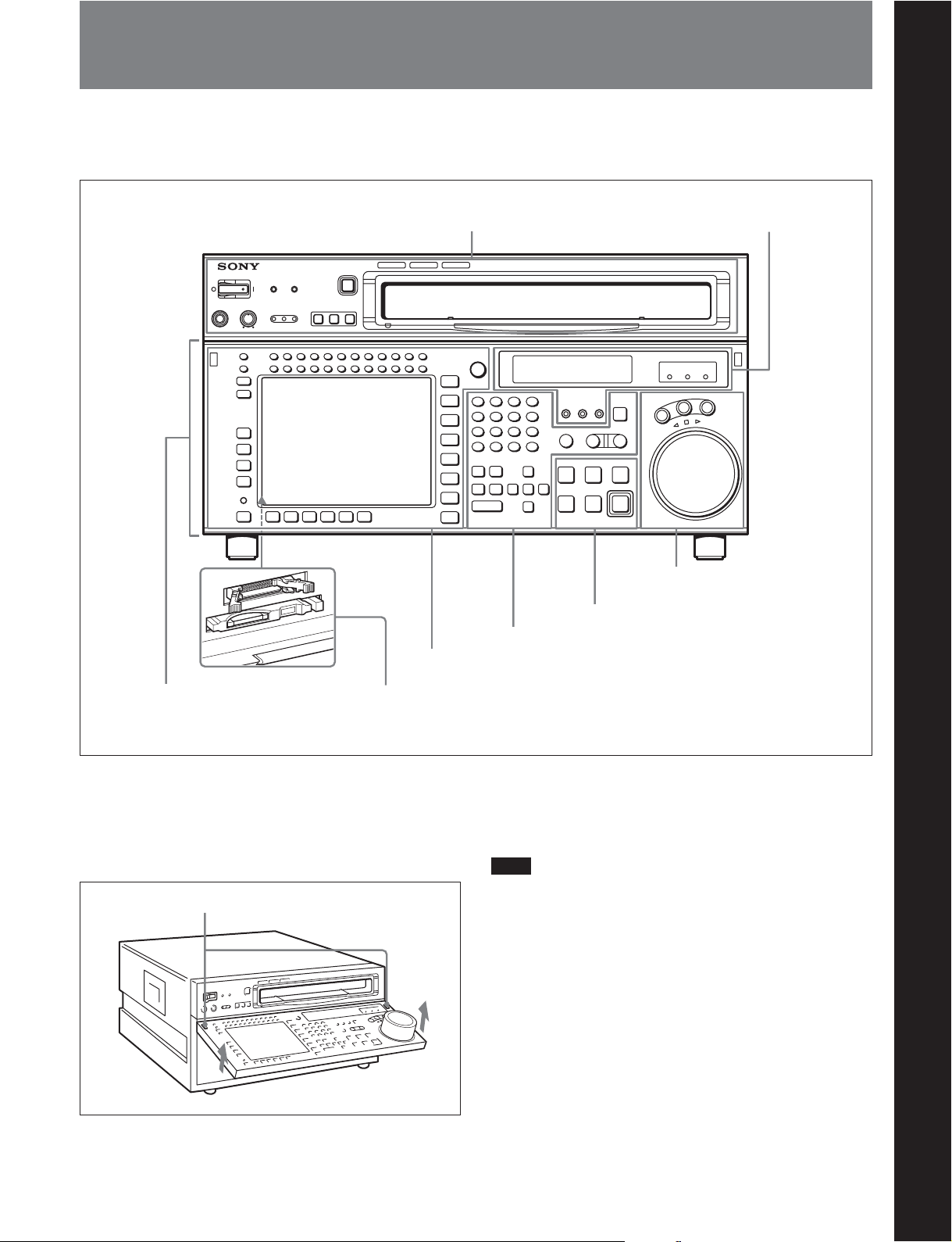
2-1 Control Panel
Chapter 2 Locations and Functions of Parts
The control panel consists of the following sections:
•Upper control panel
Upper control panel
1 Menu control section
•Lower control panel
•System set-up panel
HD DIGITAL VIDEO CASSETTE RECORDER
3 Tape transport control section
2 Editing control section
(see page 2-4)
Chapter 2 Locations and Functions of Parts
4 Display section
(see page 2-8)
SRW-5000
5 Search control section
(see page 2-9)
(see page 2-7)
(see page 2-6)
Lower control panel
System set-up panel: Access by opening the lower control panel
To open the lower control panel
Push in the lower control panel unlock buttons to open
the lower control panel. You can fix the lower control
panel in any of five positions between vertical and
horizontal.
Lower control panel unlock buttons
(see page 2-11)
To close the lower control panel
Push up the folding levers on both sides at the same
time allowing the lower control panel to close.
Note
When closing the lower control panel, be careful not to
catch your fingers in the panel.
Chapter 2 Locations and Functions of Parts 2-1
2-1 Control Panel
SRW-5000
HD DIGITAL VIDEO CASSETTE RECORDER
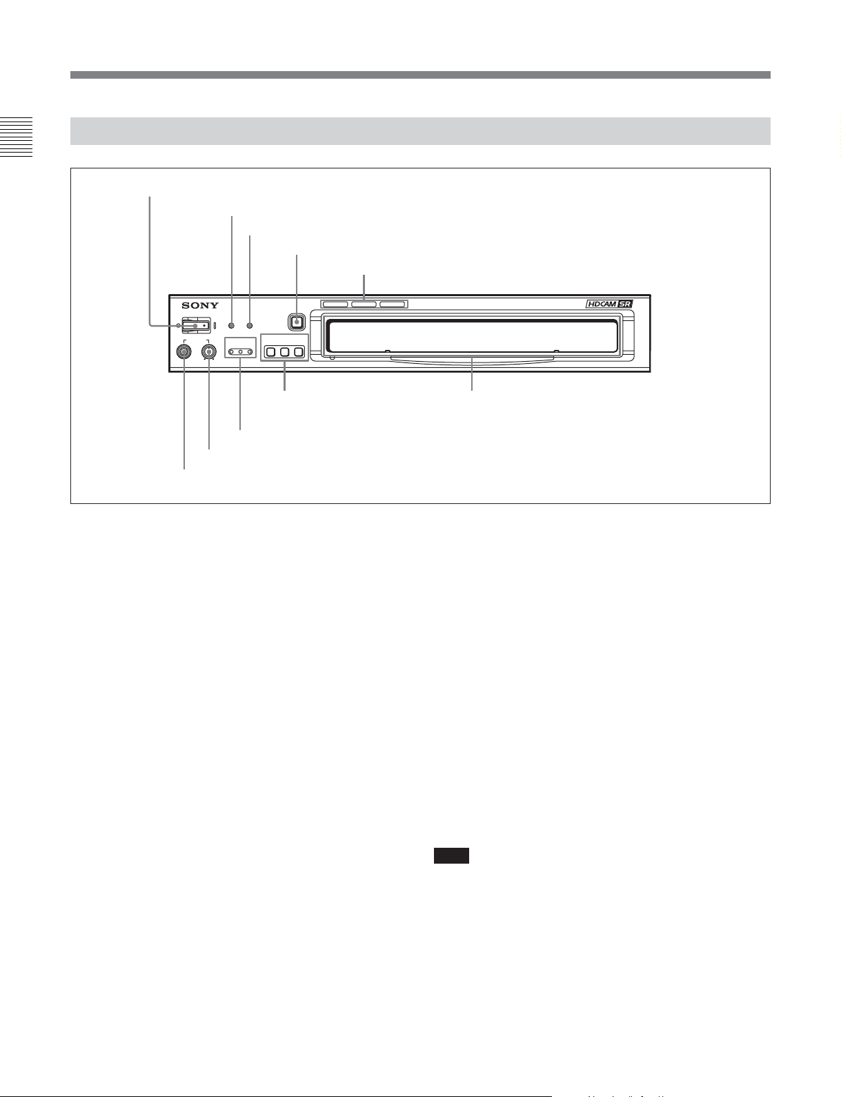
2-1-1 Upper Control Panel
Chapter 2 Locations and Functions of Parts
1 POWER switch
2 ERROR indicator
3 WARNING indicator
4 EJECT button
5 Format indicators
POWER
ERROR WARNING
PHONES
9 PHONES jack
CHANNEL
CONDITION
7 CHANNEL CONDITION indicators
8 PHONES level control
EJECT
REMOTE
ETHERNET
1(9P) 2(50P)
6 REMOTE buttons
1 POWER switch
Pressing on the ‘(’ side of this switch powers the unit
and lights up the OEL display (page 2-8) and color
display (page 2-5). To turn the unit off, press on the
‘a’ side of the switch.
2 ERROR indicator
This lights when a serious problem occurs, such as an
operational malfunction or system internal error.
You can check the details on the lower control panel.
For details, see “Error Messages and Warning Messages”
on page A-5.
3 WARNING indicator
This flashes when there is a fault in the unit. You can
check the details on the lower control panel.
Cassette compartment
5 Format indicators (Digital BETACAM/
HDCAM/HDCAM SR)
These show the format of the cassette loaded into the
unit.
6 REMOTE buttons
Press these buttons to select external equipment to be
used to remotely control the VTR.
ETHERNET: This button lights when access from
the network connected to the ETHERNET
connector on this unit is enabled.
1(9P): Press to select the unit connected to the
REMOTE 1-IN(9P) or REMOTE 1-I/O (9P)
connector. The button lights up.
2(50P): Press to select the unit connected to the
PARALLEL I/O (50P) connector (with optional
HKSR-5003). The button lights up.
For details, see “Error Messages and Warning Messages”
on page A-5.
4 EJECT button
Pressing this button automatically ejects the cassette
after several seconds.
2-2 Chapter 2 Locations and Functions of Parts
Note
When the VTR is being controlled by the external
equipment connected to the REMOTE1-IN (9P) or
REMOTE 2 PARALLEL I/O (50P) connector, all tape
transport buttons and edit operation buttons are
disabled, except the STOP and EJECT buttons. You
may also specify the disabling or enabling of all
buttons by setting the VTR SETUP menu item 008
“LOCAL FUNCTION ENABLE”.

7 CHANNEL CONDITION indicators
These show the status of the playback signal.
Blue: The playback signal status is satisfactory.
Yellow: The playback signal status is satisfactory.
However, if this indicator remains lit
continuously, head cleaning is required.
Red: The playback signal has deteriorated. However,
if this indicator remains lit continuously, head
cleaning or internal inspection is required.
8 PHONES level control
Adjusts the output level to the PHONES jack.
For details, see “5-1-2 Selecting Audio Signals” on page
5-2.
9 PHONES jack
Connect stereo headphones with 8 Ω impedance for
audio monitoring during recording, playback, and
editing. Adjust the headphone output level with the
PHONES level control.
Chapter 2 Locations and Functions of Parts
Chapter 2 Locations and Functions of Parts 2-3
2-1 Control Panel
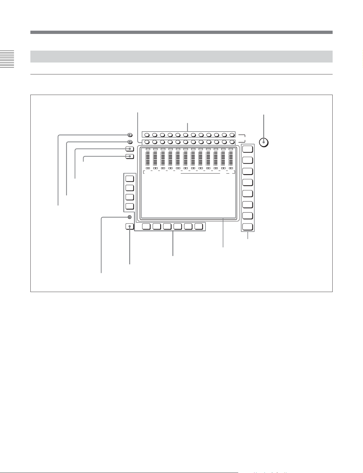
2-1-2 Lower Control Panel
Chapter 2 Locations and Functions of Parts
1 Menu Control Section
9 DISPLAY button
0 FULL/FINE button
qa PB LEVEL button
qs REC LEVEL button
8 DIAG button
1 MONITOR R buttons
OVER
OVER
dB
-10
-20
-30
-40
OVER
dB
dB
0
0
0
-10
-10
-20
-20
-30
-30
-40
-40
L R
L R
L R
CH1
CH2
CH3
EDIT PRESET VIDEO TC
F1
F2
F3
F4
DIAG
F5ALT F6 F7 F8 F9 F10
7 ALT button
2 MONITOR L buttons
OVER
OVER
OVER
dB
dB
0
-10
-10
-20
-20
-30
-30
-40
-40
L R
CH4
OVER
dB
dB
0
L R
CH5
dB
0
0
0
-10
-10
-10
-20
-20
-20
-30
-30
-30
-40
-40
-40
L R
L R
CH6
CH7
6 Function buttons
CH8
3 MULTI CONTROL knob
HOME
TC
VIDEO
AUDIO
CUE
PF1
PF2
SET UP
MULTI
CONTROL
L
MONITOR
CH12CH11CH10CH9CH8CH7CH6CH5CH4CH3CH2CH1
R
OVER
OVER
OVER
OVER
0
L R
CH10
OVER
dB
dB
0
0
-10
-10
-20
-20
-30
-30
-40
-40
L R
L R
CH11
CH12
dB
dB
0
-10
-10
-20
-20
-30
-30
-40
-40
L R
L R
CH9
4 Menu selection buttons
5 Color display
1 MONITOR R buttons
Select the audio signal output from the MONITOR
OUTPUT R connector. This assigns the desired
channel to the MONITOR OUTPUT R connector. If
you assign more than one channel to the same monitor
output connector, a mixed audio signal is output.
You can also make this setting using the VTR SETUP
menu item 808 “AUDIO MONITOR-R select”.
In the audio playback level adjustment mode, this is
used to select the channel to be adjusted.
2-4 Chapter 2 Locations and Functions of Parts
2 MONITOR L buttons
Select the audio signal output from the MONITOR
OUTPUT L connector. This assigns the desired
channel to the MONITOR OUTPUT L connector. If
you assign more than one channel to the same monitor
output connector, a mixed audio signal is output.
You can also make this setting using the VTR SETUP
menu item 807 “AUDIO MONITOR-L select”.
In the audio playback level adjustment mode, this is
used to select the channel to be adjusted.
3 MULTI CONTROL knob
Used to set the audio recording/playback level and
make settings in the SET UP menu (see page 4-63).

4 Menu selection buttons
These select the menu screen displayed on the display.
HOME button: Press this to go to the HOME menu
screen. The home menu provides settings for the
basic VTR operations and editing operations.
TC button: Press this to go to the TC (time code)
menu screen. In the time code menu, you can
Menu display:
This displays the menu screen selected by the menu
selection buttons.
Each menu screen shows the functions assigned to the
function buttons ([F1] to [F10]), and shows
simultaneously information required for time code
display settings and so on.
switch LTC/VITC, switch DF/NDF, set the time
code to be displayed on an external monitor, and
so on.
6 Function buttons
Activates the functions in each menu.
VIDEO button: Press this to go to the VIDEO menu
screen. Use it to make video related settings.
AUDIO button: Press this to go to the AUDIO menu
screen. Use it to make audio related settings.
7 ALT (alternative) button
Press to change the items displayed on the current
menu. Press again to return to the original items.
CUE button: Press this to go to the CUE menu
screen. The cue menu provides 10 pages to set cue
points. You can set up to 10 cue points per page.
You can also make settings for the Tele-File
memory label system.
PF1 button: Press this to go to the PF1 (personal
function 1) menu screen. You can register
frequently-used items in the PF1 menu. The
Note
The ALT button is frequently used in combination
with other buttons. In this manual, an operation
requiring you to press the [F1] (PRE READ) button
for example, after pressing the ALT button is
described as “Press the ALT/[F1] (PRE READ)
buttons”.
factory default setting is blank.
PF2 button: Press this to go to the PF2 (personal
function 2) menu screen. You can register
frequently-used items in the PF2 menu. The
factory default setting is blank.
8 DIAG (diagnostic) button
Hold down the SFT button (see page 2-6) in the
editing control section and press this switch to switch
to the DIAG menu.
SET UP button: Press this to go to the SET UP
menu screen. The setup menu provides functions
to save menu settings in VTR banks or save to a
memory stick, registration operations in the PF
9 DISPLAY button
This displays the down-converted output signal in the
whole color display.
buttons, VTR SETUP menu settings, and so on.
Notes
For details of menus, see “Chapter 4 Menu Settings” (page
4-1).
•Depending on the system settings, it may not be
possible to output some signals.
•This function is for a quick check of the output
5 Color display
signal, and cannot be used as a monitor.
This comprises principally the audio level display and
menu display.
Audio Level display:
In recording mode or E-E mode
1)
, this displays the
audio recording levels.
In playback mode or CONFI mode, this displays the
playback levels.
The display mode can be changed with the FULL/
FINE button. The factory default display is a reference
level of –20 dB, and peak level 0 dB.
..........................................................................................................................................................................................................
Chapter 2 Locations and Functions of Parts
1) E-E mode
An abbreviation for Electric-to-Electric mode. In this
mode, video or audio input signals are passed and output
only through the VTR’s internal circuitry, and not
through the magnetic conversion system comprising tape
and heads.
Chapter 2 Locations and Functions of Parts 2-5
2-1 Control Panel
0 FULL/FINE button
This selects the audio level meter display range.
Chapter 2 Locations and Functions of Parts
FULL: The audio level meter display is from –60 dB
to 0 dB, or –40 dB to +20 dB. Select which of
these ranges (peak level: 0 dB or +20 dB) is
displayed in the VTR SETUP menu item 814
“LEVEL METER SCALE”.
FINE: The audio level meter display range is
expanded, and displayed with a scale in steps of
0.25 dB. The reference marker LED at the center
of the level meter display range lights. When the
audio level exceeds the maximum display range,
the top OVER display flashes. When under the
minimum display range, the bottom line flashes.
qa PB (playback) LEVEL button
Press this button to enter the playback audio level
adjustment mode. In this mode, you can use the
MONITOR R button to select the adjustment target
channels from channels 1 to 12. While watching the
audio level meter, turn the MULTI CONTROL knob
for a desired audio level.
Clicking the MULTI CONTROL knob resets the
playback audio level to the factory set level (a
reference level of 0 dB is displayed for a +4 dBm
input). Clicking the MULTI CONTROL knob again
restores the adjusted level.
Press this button again to exit from the playback audio
level adjustment mode, and the MONITOR L and R
buttons return to the normal status (this status is called
the “MONITOR SELECT mode”).
qs REC (recording) LEVEL button
Press this button to enter the recording audio level
adjustment mode. In this mode, you can use the
MONITOR L button to select the adjustment target
channels from channels 1 to 12. While watching the
audio level meter, turn the MULTI CONTROL knob
for a desired audio level.
Clicking the MULTI CONTROL knob resets the
recording audio level to the factory set level (a
reference level of 0 dB is displayed for a +4 dBm
input). Clicking the MULTI CONTROL knob again
restores the adjusted level.
Press this button again to exit from the recording audio
level adjustment mode, and the MONITOR L and R
buttons return to the normal status (this status is called
the “MONITOR SELECT mode”).
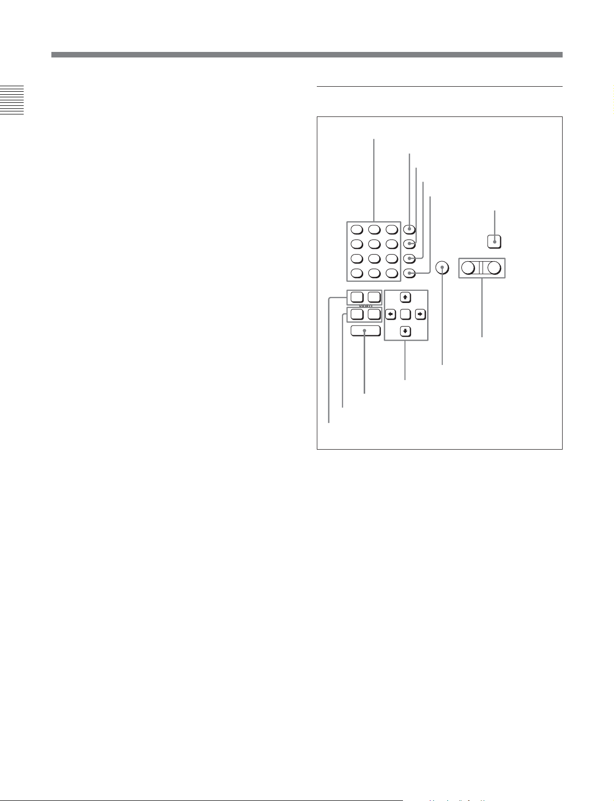
2 Editing Control Section
1 Numeric buttons and +/– buttons
2 SFT button
3 RCL button
4 CLR button
5 SET button
6 INPUT CHECK
button
8
7
F
E
5
4
C
B
2
1
A
+
0
AUDIO
IN OUT
VIDEO
IN OUT
ENTRY
0 ENTRY button
qa IN/OUT buttons
qs AUDIO IN/OUT buttons
SFT
9
RCL
6
D
CLR
3
SET
–
9 Cursor buttons
AUTO
8 AUTO button
1 Numeric buttons and +/– buttons
Press to input time data or edit points data at the cursor
position in menu display. Press buttons 0 to 5 while
holding down the SFT button to input hexadecimal A
to F for user bits. Use the +/– buttons to increase or
decrease settings.
2 SFT (shift) button
Press buttons 0 to 5 while holding down this button to
input hexadecimal A to F for user bits.
Use also in combination with other buttons to perform
other operations.
3 RCL (recall) button
Press to recall the previous setting, etc.
4 CLR (clear) button
Press to clear input data.
INPUT
CHECK
PLAYER RECORDER
7 PLAYER/
RECORDER
buttons
2-6 Chapter 2 Locations and Functions of Parts
5 SET button
Press to finalize input data.
6 INPUT CHECK button
While you hold down this button, the input signal is
output from the monitor output connector, so that you
can monitor the input video and audio.
When the LTC/VITC time code is shown on the
display, you can check the time code generator.
7 PLAYER/RECORDER buttons
Select which VTR is to be controlled by this VTR’s
control panel during editing when this VTR is used as
a recorder and an external VTR is connected to the
REMOTE 1-IN(9P) or REMOTE 1-I/O(9P) connector
as a player.
PLAYER: The tape transport buttons and editing
operation buttons on the control panel control the
external player VTR.
RECORDER: The tape transport buttons and
editing operation buttons on the control panel
control the recorder VTR (this VTR).
The PLAYER/RECORDER buttons have no effect
when using this VTR alone.
8 AUTO button
When this button is pressed, it lights up and auto edit
mode is activated.
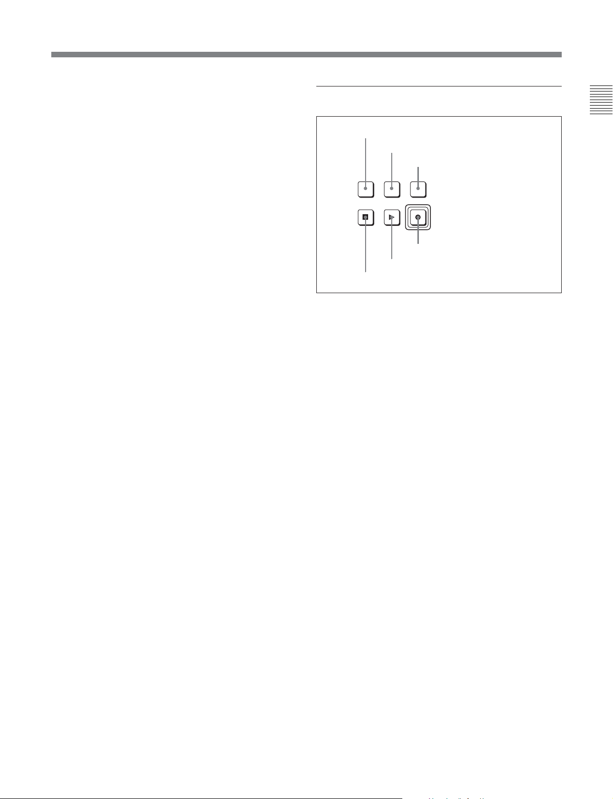
3 Tape Transport Control Section
1 STANDBY button
2 PREROLL button
3 PREVIEW/REVIEW button
PREVIEW/
REVIEW
PREROLLSTANDBY
REC/EDIT
PLAY
STOP
4 REC/EDIT button
5 PLAY button
6 STOP button
1 STANDBY button
Press this button in other than standby mode to make it
light up and place the VTR in standby mode. The
head drum rotates in standby mode, thereby shortening
the time required for the tape to start.
Press this button while in standby mode to turn the
button off and exit from standby mode. The head
drum stops rotating and the tape tension is released. If
the VTR remains in standby mode for more than eight
minutes (factory setting), standby mode is
automatically canceled in order to safeguard the tape.
Chapter 2 Locations and Functions of Parts
9 Cursor buttons
Use to move the cursor (shown in reverse video) on
the display. Also use to change menu settings.
0 ENTRY button
Press to enter an edit or cue point.
While holding down this button, press either the
AUDIO IN or AUDIO OUT button, or the IN or OUT
button.
qa IN/OUT buttons
To set a IN or OUT point during editing, press either
of these buttons while holding down the ENTRY
button.
qs AUDIO IN/AUDIO OUT buttons
To set an AUDIO IN or AUDIO OUT point during
insert editing, press either of these buttons while
holding down the ENTRY button.
2 PREROLL button
Press to run the tape to the preroll point (a position
factory set to five seconds before the IN point).
Press this button while holding down the IN, OUT,
AUDIO IN or AUDIO OUT button to cue up the tape
at the corresponding edit point.
For details on changing the preroll time, see “4-2-6 Setting
the Preroll Time (PREROLL TIME)” on page 4-16.
3 PREVIEW/REVIEW button
After the edit points are set, press this button to
preview, on the monitor connected to the recorder, the
effect of the edit before it is performed. In this
operation, the tape runs, but no editing is carried out.
If you press this button after carrying out an edit, the
results of the edit are played back on the monitor
connected to the recorder.
Chapter 2 Locations and Functions of Parts 2-7
2-1 Control Panel
4 REC/EDIT (recording/edit) button
Press this button while holding down the PLAY button
Chapter 2 Locations and Functions of Parts
to start recording.
If you press this button in play mode, manual editing
begins. After setting edit points, if you press this
button while the AUTO button is lit, automatic editing
is performed.
5 PLAY button
Press to start playback.
Press this button while holding down the REC/EDIT
button to start recording.
Pressing this button during recording or manual editing
changes the VTR to playback mode.
6 STOP button
Press this button to stop recording or playback.
When you insert the cassette, the VTR automatically
enters STBY OFF mode.
The STOP button flashes in the following cases.
•The [F2] (SERVO REF) button in the PF1 menu is set
to “input” but there is no video input signal.
•The [F2] (SERVO REF) button in the PF1 menu is set
to “ext” but there is no external reference video
signal.
•The input signal is out of synchronization with the
external reference video signal.
You can change the setting of the VTR SETUP menu
item 102 “REFERENCE SYSTEM ALARM” so that
the STOP button will not flash in these cases.
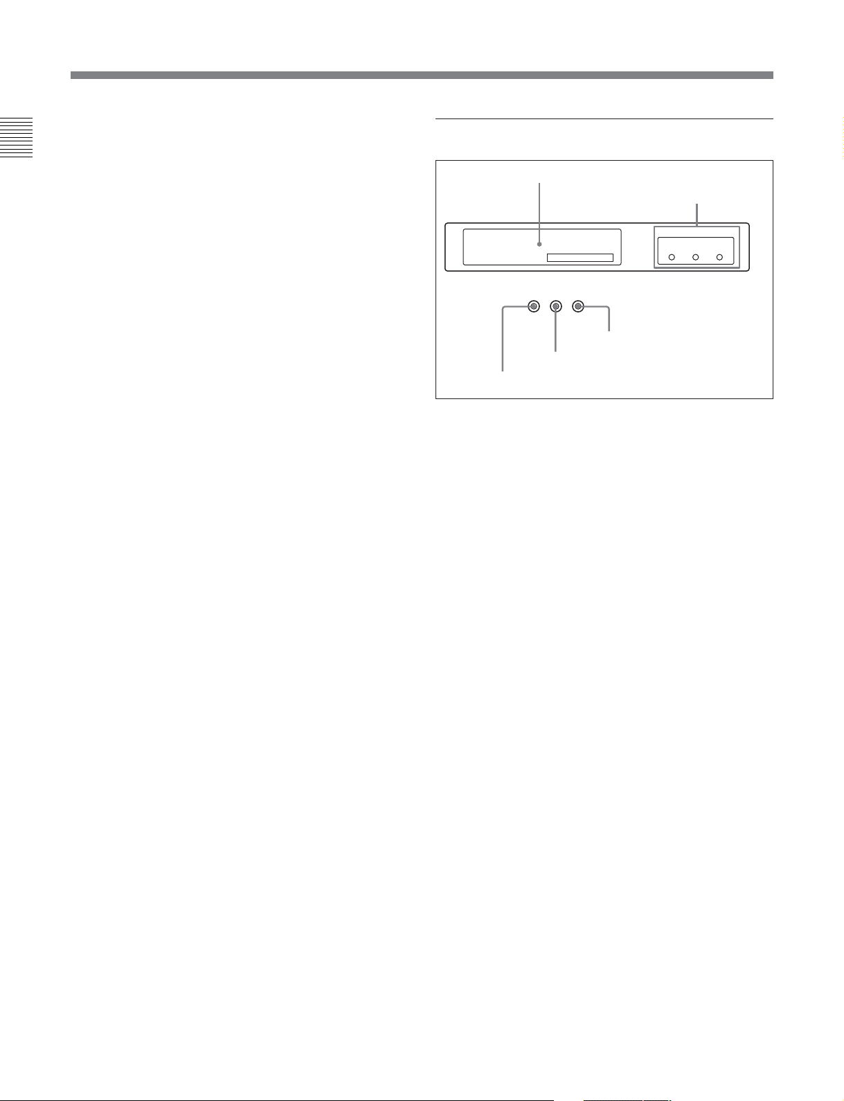
4 Display Section
1 OEL display
2 REF SYNC indicators
SYS: 59.94i 1080 4:2:2 HDCAM SR
PB :
_ _ _ _ _ _ _ _ _ _ _ _ _ _ _ _ _ _ _ _ _ _ _ _ _ _
5 REC INHIBIT indicator
TCR 00:12:37:28
REC
PREREAD
INHIBIT SERVO
4 SERVO indicator
3 PREREAD indicator
1 OEL display
This shows the following.
SYS: Shows the recording system information (signal
standard and tape format).
PB: Shows the information recorded on the tape
(signal standard and tape format) while being
played back.
FC: Shows the converted signal standard when an
HKSR-5001 board is installed.
TCX: Shows the LTC/VITC and DF/NDF settings,
or the time code sent to the external monitor.
2 REF SYNC (reference signal) indicators
These indicate the signal selected as the reference
signal. If there is no reference signal input to the
selected connector, the STOP button flashes.
EXT SD: Lights when “extern SD” is selected by the
VTR SETUP menu item 006 “EXTERNAL
REFERENCE select”.
EXT HD: Lights when “extern HD” is selected by
the VTR SETUP menu item 006 “EXTERNAL
REFERENCE select”.
INPUT VIDEO: Lights when “INPUT” is selected
by the VTR SETUP menu item 005 “SERVE/AV
REFERENCE select”.
REF SYNC
EXTSDEXT
INPUT
VIDEO
HD
2-8 Chapter 2 Locations and Functions of Parts
3 PREREAD indicator
Lights up during preread mode.
For more information about PREREAD, see “6-2-3 Preread
Editing” on page 6-15.
4 SERVO indicator
Lights up when the drum servo and capstan servo are
locked.

5 REC INHIBIT indicator
The status of this indicator depends on the setting of
the [F2] (REC INH) button in the HOME menu and the
state of the record-protect plug on the cassette.
Setting of the [F2]
(REC INH) button in
the HOME menu
all Recording disabled Lit/flashing
crash REC, video/
CTL, audio/CTL
off Recording disabled Lit/flashing
a) Toggling between lit/flashing settings is possible using
the VTR SETUP menu item 104 “REC INHIBIT LAMP
FLASHING”.
State of the recordprotect plug on the
REC INHIBIT
indicator
cassette
Recording allowed Lit
Recording disabled Lit/flashing
UnlitRecording allowed
Recording allowed Unlit
a)
a)
a)
a)
5 Search Control Section
1 SHUTTLE button
2 JOG button
3 VAR button
V
G
A
O
J
E
L
T
T
U
H
S
E
S
R
E
V
E
R
R
F
O
R
W
A
Chapter 2 Locations and Functions of Parts
R
D
Recording, editing, and selection of assemble and
insert modes are possible only when the indicator is
off.
4 Search dial
1 SHUTTLE button
Press to enter shuttle mode. In this mode, the button
lights and playback at the speed corresponding to the
angle of rotation of the search dial is possible. The
playback speed range depends on the frame frequency
of the unit. In this mode, the search dial clicks at the
positions for 0 (still picture), –10 and +10 times
normal playback speed.
Frame frequency Playback speed
23.98/24 Hz Ranging from ±50
25 Hz Ranging from ±48
29.97/30 Hz Ranging from ±40
2 JOG button
Press to select jog mode. In this mode, the button
lights up and playback at –1 to +1 or –2 to +2 times
normal playback speed (determined by the setting in
the VTR SETUP menu item 107 “JOG DIAL
RESPONSE”) is possible. In this mode, the search
dial does not click.
3 VAR (variable) button
Press to select variable speed playback mode for
noiseless playback in a maximum range of –1 to +2
times normal playback speed. Playback exceeding this
speed range is not possible. The search dial clicks at
the positions for still-picture and normal playback
speed.
Chapter 2 Locations and Functions of Parts 2-9

2-1 Control Panel
4 Search dial
Rotate to search for edit points. Rotate the dial
Chapter 2 Locations and Functions of Parts
clockwise for forward playback (the B indicator lights
up) or counterclockwise for reverse playback (the b
indicator lights up). The x indicator lights up while
the VTR is in stop mode.
Shuttle mode: The playback speed corresponds to
the angle of rotation of the search dial. The
playback speed range depends on the frame
frequency of the unit. (See item 1SHUTTLE
button.) The dial clicks at the positions
corresponding to 0 (still picture), –10 and +10
times normal playback speed.
Jog mode: The playback speed corresponds to the
rotational speed of the dial (–1 to +1 or –2 to +2
times normal playback speed depending on the
setting of the VTR SETUP menu item 107 “JOG
DIAL RESPONSE”). The dial does not click.
Variable speed playback mode: Noiseless playback
in the range –1 to +2 times normal speed is
possible. The speed settings can be changed using
the menu. The dial clicks at the positions for stillpicture and normal playback speed.
Capstan override mode: Rotating the dial while
holding down the PLAY button changes the
playback speed by up to ±15%.
2-10 Chapter 2 Locations and Functions of Parts
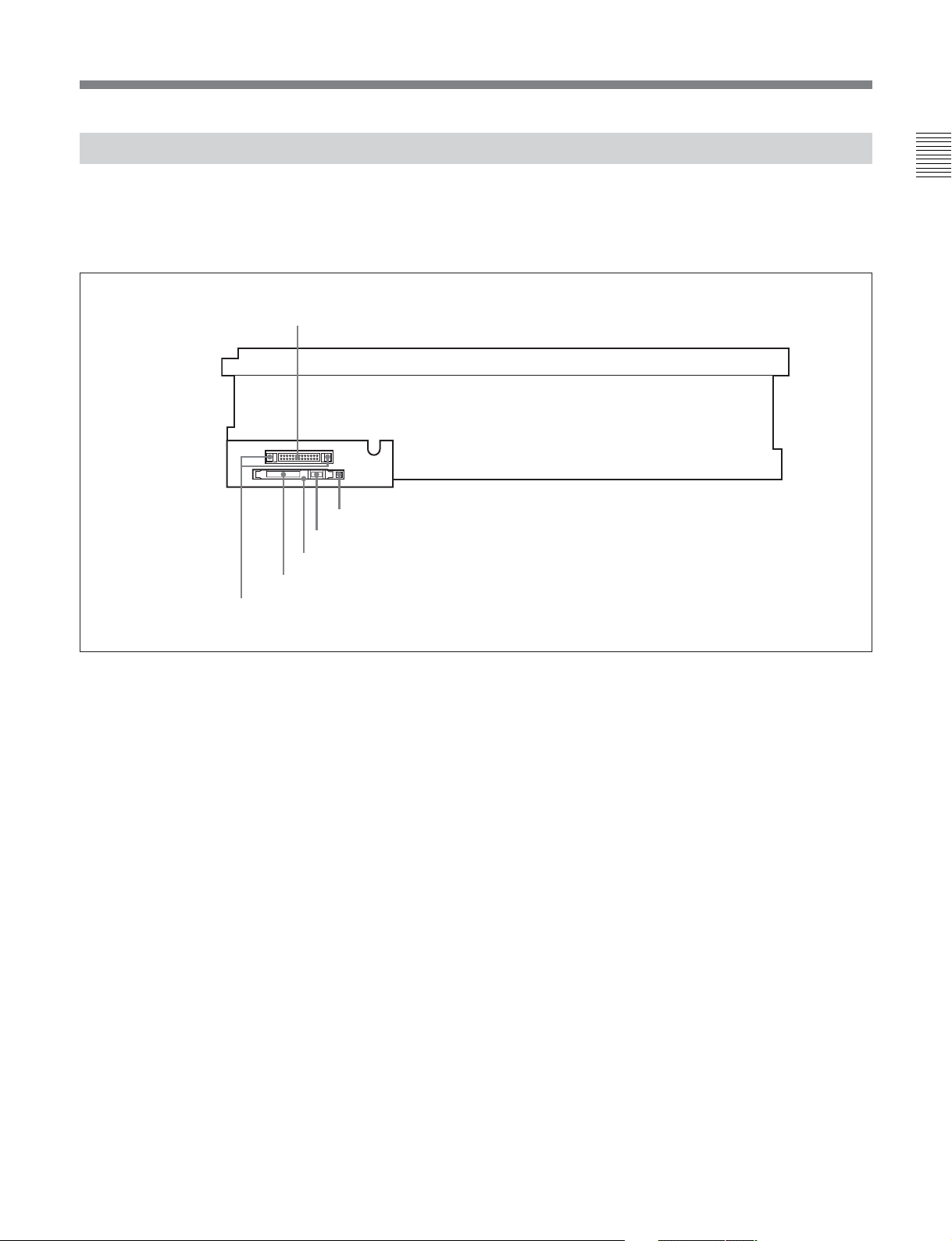
2-1-3 System Set-Up Panel
Lift the lower control panel up to its horizontal
position to access the system set-up panel.
CONTROL PANEL connector
CONTROL PANEL
Card slot eject button
Memory stick eject button
Memory stick receptacle
PCM CIA card slot
Harness restraint
Chapter 2 Locations and Functions of Parts
For details, see “3-4 Using a Memory Stick” on page 3-9.
Chapter 2 Locations and Functions of Parts 2-11
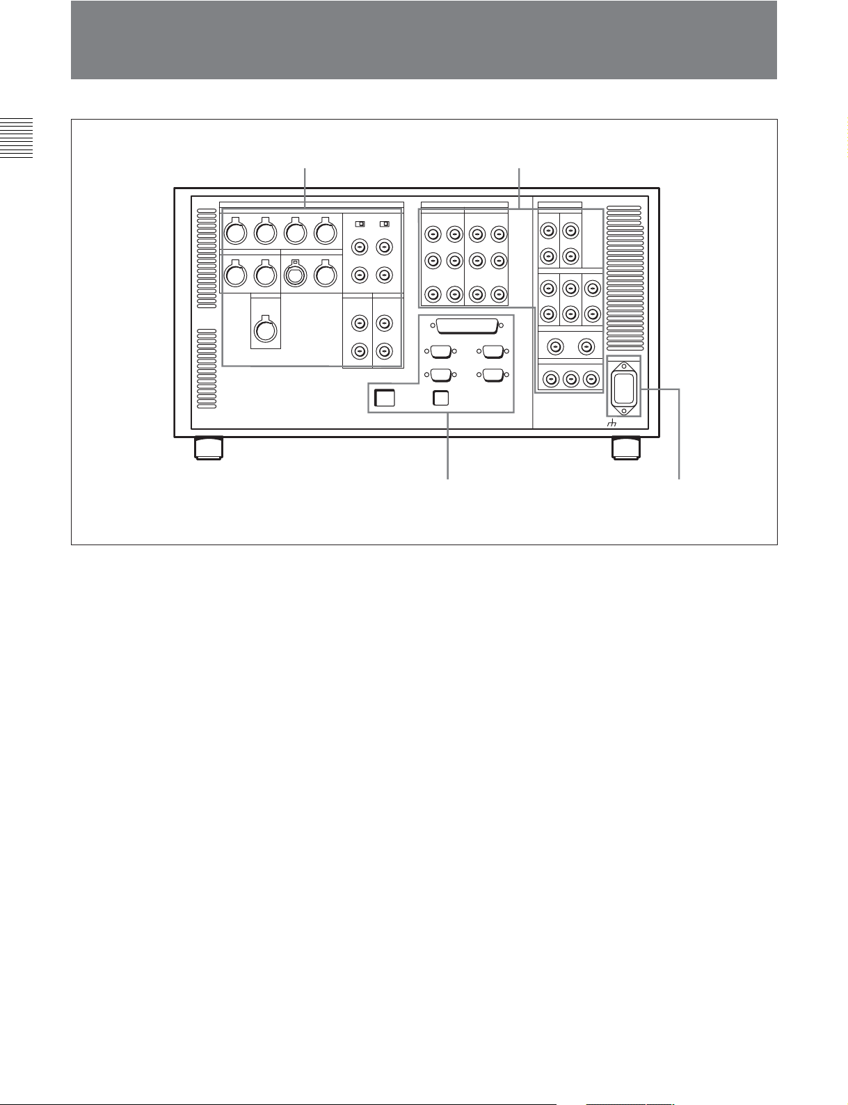
2-2 Connector Panel
2-2 Connector Panel
Chapter 2 Locations and Functions of Parts
1 ANALOG I/O section
(see page 2-13)
2 DIGITAL I/O section
3 Remote input/output section
(see page 2-16)
(see page 2-15)
4 Power supply
(see page 2-16)
2-12 Chapter 2 Locations and Functions of Parts
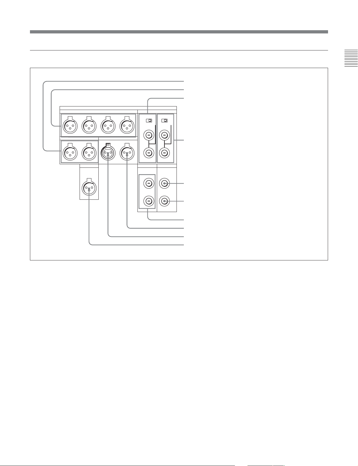
1 ANALOG I/O (input/output) section
ANALOG I/O
REF INPUT
1
OFF ON
CH1
AUDIO OUTPUT
CH2 CH3 CH4
2 (OPTION)
OFF ON
75Ω 75Ω
Chapter 2 Locations and Functions of Parts
1 MONITOR OUTPUT L/R connectors
2 AUDIO OUTPUT CH1 to CH4 connectors
3 REF. INPUT 1 connectors and 75 Ω termination switch
MONITOR OUTPUT
RLINOUT
CUE
OUT
TIME CODE
HD REF OUT SD OUT
SYNC
1
2
COMPOSITE
1 MONITOR OUTPUT L/R connectors (XLR-3-
31)
These output the audio signals for monitoring L and R
channels. To select the signals to output, use the
MONITOR R and MONITOR L buttons on the lower
control panel. A menu setting can be made so that
volume can be controlled with the PHONES level
control.
For details, see “5-1-2 Selecting Audio Signals”on page
5-2.
2 AUDIO OUTPUT CH1 to CH4 connectors
(XLR-3-31)
These output up to four analog audio signal lines
(channels 1 to 4).
4 REF. INPUT 2 connectors and 75 Ω termination switch
5 SD OUT SYNC connector
6 SD OUT COMPOSITE connector
7 HD REF. OUT connectors
8 TIME CODE OUT connector
9 TIME CODE IN connector
0 CUE OUT connector
3 REF. INPUT 1 connectors (BNC) and 75 Ω
termination switch
Input a reference video signal of the selected field
frequency. Select HD or SD with the VTR SETUP
menu item 006 “EXTERNAL REFERENCE select”.
When HD is selected, input a tri-level SYNC signal.
When SD is selected, input a video signal with chroma
burst (VBS) or a monochrome video signal (VS).
A loop-through connection is possible. Set the 75 Ω
termination switch to OFF if you are using a loopthrough connection and set it to ON if you are not
using a loop-through connection.
Chapter 2 Locations and Functions of Parts 2-13

2-2 Connector Panel
4 REF. INPUT 2 connectors (BNC) and 75 Ω
termination switch
Chapter 2 Locations and Functions of Parts
Input a reference video signal of the field frequency
selected for the format converter output. Select HD or
SD with the VTR SETUP menu item 006
“EXTERNAL REFERENCE select”. When HD is
selected, input a tri-level SYNC signal for external
synchronization. When SD is selected, input a video
signal with chroma burst (VBS) or a monochrome
video signal (VS). A loop-through connection is
possible. Set the 75 Ω termination switch to OFF if
you are using a loop-through connection and set it to
ON if you are not using a loop-through connection.
5 SD OUT SYNC connector (BNC)
This outputs an NTSC or PAL signal for external
synchronization.
Note
The output phase is the same as that of the composite
signal output from the SD OUT COMPOSITE
connector.
Because the output phase changes with the operation
mode of the VTR, use this for synchronization with the
video monitor.
6 SD OUT COMPOSITE connector (BNC)
Outputs an analog composite signal for a video
monitor. When the ALT/[F6] (CHARA SUPER)
setting in the TC menu is on, character signals such as
time codes are superimposed on the output.
8 TIME CODE OUT connector (XLR-3-31,
female)
Outputs the following time codes according to the
VTR operation mode.
In playback mode: Playback time code
In recording mode: Time code generated by the
internal time code generator, or time code input to
the TIME CODE IN connector.
To select the output signal, use the VTR SETUP menu
item 613 “TC OUTPUT SIGNAL IN REGEN
MODE.”
Setting Description
off tape In playback mode, playback time code signal
regene Only when the servo is locked in playback
through
is output. In recording mode, TCG time code
signal is output.
mode, playback time code signal is
regenerated and output. In all other cases,
output is the same as for the "off tape"
setting.
The time code signal from the TIME CODE
IN connector is output as is. (Used for
cascade connections.)
(For more information about cascade
connections, see 3-1-3 “Cascade
Connection” on page 3-3.)
9 TIME CODE IN connector (XLR-3-32, male)
Accepts external time code for recording to tape.
Connect to the time code output connector of the
external equipment.
7 HD REF. OUT connectors (BNC)
Output an HD tri-level sync signal during tape
playback.
2-14 Chapter 2 Locations and Functions of Parts
0 CUE OUT (cue output) connector (XLR-3-31,
female)
Outputs cue track audio during HDCAM or Digital
Betacam playback.
Note
There is no cue track on an HDCAM-SR tape, and
therefore no output.
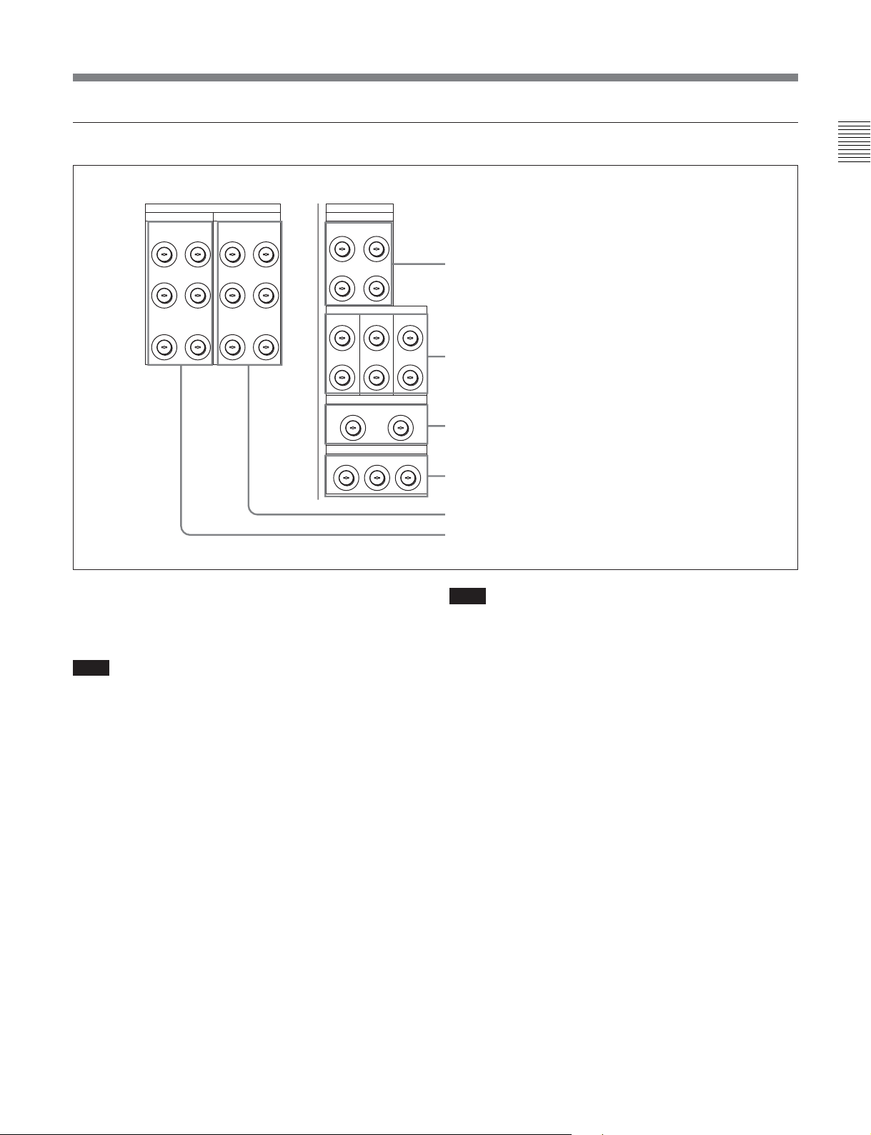
2 DIGITAL I/O (input/output) section
Chapter 2 Locations and Functions of Parts
DIGITAL I/O (AES/EBU)
AUDIO
CH1/2 CH3/4 CH1/2 CH3/4
CH5/6 CH7/8 CH5/6 CH7/8
CH9/10 CH11/12 CH9/10 CH11/12
OUTPUT
AUDIO
HD SDI INPUTINPUT
A
B(OPTION)
A
B(OPTION)AB(OPTION)AB(OPTION)
FORMAT CONV. OUT (OPTION)
12MONITOR
1 HD SDI (SDI video/audio) INPUT A/B
connectors (BNC)
These accept SDI video/audio signals.
DIGITAL I/O
INPUT
MONITOR
B INPUT
MONITOR
HD SDI OUTPUT
23 MONITOR
1
12
MONITOR
SD SDI OUT
1 HD SDI INPUT A/B connectors
2 HD SDI OUTPUT connectors
3 FORMAT CONV. OUT (OPTION) connectors
4 SD SDI OUT connectors
5 DIGITAL I/O (AES/EBU) OUTPUT connectors
6 DIGITAL I/O (AES/EBU) INPUT connectors
This is only valid when the optional HKSR-5001
format converter board is installed.
Note
Note
The INPUT MONITOR connectors are for use with an
input monitor and does not follow the standards for
output.
2 HD SDI (SDI video/audio) OUTPUT connectors
(BNC)
These output up to three sets of SDI video/audio
signals.
When the ALT/[F6] (CHARA SUPER) buttons are set
to ON in the TC menu, time data or other text data is
superimposed on the output signal.
3 FORMAT CONV. OUT (OPTION) connectors
(BNC)
These output two sets of format-converted video/audio
signals.
When the ALT/[F5] (PD CHARA) buttons are set to
ON in the TC menu, the output has time data or other
text superimposed on the signal.
4 SD SDI (1/2/monitor) OUT connectors (BNC)
These output up to three sets of video/audio signals.
When the ALT/[F6] (CHARA SUPER) buttons are set
to ON in the TC menu, time data or other text data is
superimposed on the output from the MONITOR
OUTPUT L/R connector.
5 DIGITAL I/O (AES/EBU) OUTPUT connectors
(BNC)
These output digital signals in AES/EBU format for
channels 1 to 12.
6 DIGITAL I/O (AES/EBU) INPUT connectors
(BNC)
These accept digital signals in AES/EBU format for
channels 1 to 12.
Chapter 2 Locations and Functions of Parts 2-15
2-2 Connector Panel
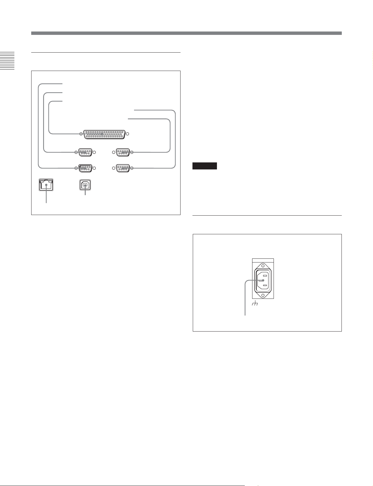
3 Remote input/output section
Chapter 2 Locations and Functions of Parts
1 RS232C connector
2 REMOTE1-IN connector
3 REMOTE 2 PARALLEL I/O connector
4 VIDEO CONTROL connector
5 REMOTE1-I/O connectors
REMOTE 1-IN(9P) REMOTE 1-I/O(9P)
ETHERNET
7 ETHERNET connector
1 RS232C connector (RS-232C serial interface)
(D-sub 9-pin)
This is used for manufacturing and services.
REMOTE 2 PARALLEL I/O(50P)
RS232C
USB
6 USB connector
VIDEO CONROL
5 REMOTE 1-I/O (9P) connectors
(D-sub 9-pin)
Use this, with the supplied 9-pin remote control cable,
to connect the unit to another SRW-5000 unit or
another HD VTR unit to carry out editing with a BVEseries editor BVE-900/2000/9000/9100.
6 USB connector
This is used for manufacturing and services.
7 ETHERNET connector
Used for monitoring the VTR by SNMP, or for setting
or changing VTR settings by HTTP.
Caution
When using a modular ETHERNET connector
For safety, do not connect to the connector for
peripheral device wiring that might have excessive
voltage.
4 Power supply
2 REMOTE 1-IN (9P) connector
Use this, with the supplied 9-pin remote control cable,
to connect the unit to another SRW-5000 unit or
another HD VTR unit to carry out editing with a BVEseries editor BVE-900/910/2000/9000/9100.
3 REMOTE 2 PARALLEL I/O connector (D-sub
50-pin)
Inputs an external remote control signal.
For details, refer to the Maintenance Manual Volume 1.
4 VIDEO CONTROL (Digital Video Processor
Control) connector (D-sub 9-pin)
Connects to the optional HKDV-503 HD Digital Video
Controller to enable remote control of the internal
digital video processor. Turn off the power before
connecting the remote controller.
AC IN
-AC IN connector
-AC IN connector (3-pin)
Connects to an AC outlet using an appropriate power
cord.
2-16 Chapter 2 Locations and Functions of Parts
 Loading...