

Page 1

HD PORTABLE DIGITAL RECORDER
SRW-1
HD VIDEO PROCESSOR
SRPC-1
OPTICAL INTERFACE UNIT
HKSR-101
OPERATION MANUAL [English]
1st Edition (Revised 2)
Page 2
WARNING
To prevent fire or shock hazard, do not
expose the unit to rain or moisture.
To avoid electrical shock, do not open the
cabinet. Refer servicing to qualified
personnel only.
For the customers in the USA
This equipment has been tested and found to comply with the
limits for a Class A digital device, pursuant to Part 15 of the
FCC Rules. These limits are designed to provide reasonable
protection against harmful interference when the equipment is
operated in a commercial environment. This equipment
generates, uses, and can radiate radio frequency energy and,
if not installed and used in accordance with the instruction
manual, may cause harmful interference to radio
communications. Operation of this equipment in a residential
area is likely to cause harmful interference in which case the
user will be required to correct the interference at his own
expense.
You are cautioned that any changes or modifications not
expressly approved in this manual could void your authority to
operate this equipment.
The shielded interface cable recommended in this manual
must be used with this equipment in order to comply with the
limits for a digital device pursuant to Subpart B of Part 15 of
FCC Rules.
For the customers in the USA and Canada
RECYCLING LITHIUM-ION BATTERIES
Lithium-Ion batteries are recyclable.
You can help preserve our environment
by returning your used rechargeable
batteries to the collection and recycling
location nearest you.
For more information regarding recycling of rechargeable
batteries, call toll free 1-800-822-8837, or visit
http://www.rbrc.org/
Caution: Do not handle damaged or leaking lithium-ion
batteries.
For the customers in Europe
This product with the CE marking complies with the EMC
Directive (89/336/EEC) issued by the Commission of the
European Community.
Compliance with these directives implies conformity to the
following European standards:
• EN55103-1: Electromagnetic Interference (Emission)
• EN55103-2: Electromagnetic Susceptibility (Immunity)
This product is intended for use in the following
Electromagnetic Environment(s):
E1 (residential), E2 (commercial and light industrial), E3
(urban outdoors) and E4 (controlled EMC environment, ex. TV
studio).
For HKSR-101 only
This Optical Interface Unit is classified as a CLASS 1
LASER PRODUCT.
Laser diode properties
Wave length: 1310±20 nm
Emission duration: Continuous
Laser output power: 10 mW (max.)
Daten der Laserdiode
Wellenlänge: 1310±20 nm
Emissionsdauer: Kontinuierlich
Laser-Ausgangsleistung: 10 mW (max.)
Laserdiode data
Bølgelængde: 1310±20 nm
Strålingsvarighed: Kontinuerlig
Lasereffekt: 10 mW (max.)
Laserdiodens egenskaper
Våglängd: 1310±20 nm
Strålningstid: utan avbrott
Laseruteffekt: 10 mW (max.)
Laserdiodens egenskaper
Bølgelengde: 1310±20 nm
Emisjonslengde: Kontinuerlig
Laser utgangseffekt: 10 mW (max.)
CAUTION
The use of optical instruments with this product will
increase eye hazard.
CAUTION
Use of controls or adjustments or performance of
procedures other than those specified herein may result in
hazardous radiation exposure.
This device complies with part 15 of the FCC Rules.
Operation is subject to the following two conditions: (1) this
device may not cause harmful interference, and (2) this
device must accept any interference received, including
interference that may cause undesired operation.
For customers in Canada
This Class A digital apparatus complies with Canadian
ICES-003.
Voor de Klanten in Nederland
Gooi de batterij niet weg maar lever deze in als klein chemisch
afval (KCA).
2
Page 3

VORSICHT
Um Feuergefahr und die Gefahr eines
elektrischen Schlages zu vermeiden, darf
das Gerät weder Regen noch Feuchtigkeit
ausgesetzt werden.
Pour plus d’informations sur le recyclage des accumulateurs,
téléphonez au numéro gratuit
1-800-822-8837 (Etats-Unis et Canada uniquement), ou
visitez http://www.rbrc.org/
Avertissment: Ne pas utiliser des accumulateurs aux ions de
lithium qui sont endommagés ou qui fuient.
Um einen elektrishen Schlag zu vermeiden,
darf das Gehäuse nicht geöffnet werden.
Überlassen Sie Wartungsarbeiten stets nur
qualifiziertem Fachpersonal.
Für Kunden in Europa
Dieses Produkt besitzt die CE-Kennzeichnung und erfüllt die
EMV-Richtlinie (89/336/EWG) der EG-Kommission.
Angewandte Normen:
• EN55103-1: Elektromagnetische Verträglichkeit
(Störaussendung)
• EN55103-2: Elektromagnetische Verträglichkeit
(Störfestigkeit),
für die folgenden elektromagnetischen Umgebungen:
E1 (Wohnbereich), E2 (kommerzieller und in beschränktem
Maße industrieller Bereich), E3 (Stadtbereich im Freien) und
E4 (kontrollierter EMV-Bereich, z.B. Fernsehstudio).
Für Kunden in Deutshland
Entsorgungshinweis: Bitte werfen Sie nur entladene Batterien
in die Sammelboxen beim Handel oder den Kommunen.
Entladen sind Batterien in der Regel dann, wenn das Gerät
abschaltet und signalisiert “Batterie leer” oder nach längerer
Gebrauchsdauer der Batterien “nicht mehr einwandfrei
funktioniert”. Um sicherzugehen, kleben Sie die Batteriepole
z.B. mit einem Klebestreifen ab oder geben Sie die Batterien
einzeln in einen Plastikbeutel.
Pour les utilisateurs au Canada (HKSR-101 seulement)
Cet appareil numérique de la classe A est comforme à la
norme NMB-003 du Canada.
Pour les clients européens
Ce produit portant la marque CE est conforme à la Directive
sur la compatibilité électromagnétique (EMC) (89/336/CEE)
émise par la Commission de la Communauté européenne.
La conformité à cette directive implique la conformité aux
normes européennes suivantes:
• EN55103-1: Interférences électromagnétiques (émission)
• EN55103-2: Sensibilité électromagnétique (immunité)
Ce produit est prévu pour être utilisé dans les environnements
électromagnétiques suivants:
E1 (résidentiel), E2 (commercial et industrie légère), E3
(urbain extérieur) et E4 (environnement EMC contrôlé, ex.
studio de télévision).
For the customers in Taiwan only
AVERTISSEMENT
Afin d’éviter tout risque d’incendie ou
d’électrocution, ne pas exposer cet
appareil à la pluie ou à l’humidité.
Afin d’écarter tout risque d’électrocution,
garder le coffret fermé. Ne confier
l’entretien de l’appareil qu’à un personnel
qualifié.
Pour les utilisateurs aux Etats-Unis et au Canada.
RECYCLAGE DES ACCUMULATEURS AUX IONS DE
LITHIUM
Les accumulateurs aux ions de lithium sont
recyclables.
Vous pouvez contribuer à préserver
l’environnement en rapportant les piles
usées dans un point de collection et
recyclage le plus proche.
3
Page 4

Table of Contents
Chapter 1 Overview
1-1 Features.................................................7
1-1-1 Principal Features ................................ 7
1-1-2 HDCAM-SR Format............................8
1-2 System Configuration.........................10
Chapter 2 Names and Functions of
Parts
2-1 SRW-1 ..................................................11
2-1-1 Principal Sections .............................. 11
2-1-2 Control Panel .....................................12
2-1-3 Display...............................................14
2-1-4 Connector Panel................................. 16
2-2 SRPC-1.................................................18
Chapter 3 Preparations
3-1 Assembly.............................................21
3-1-1 Joining the SRW-1 and SRPC-1........ 21
3-1-2 Using the Control Panel Extension
Cable ..................................................23
3-2 Connections ........................................25
3-2-1 Connections for Recording ................25
3-2-2 Connections for Playback ..................27
3-3 About Reference Sync Signals.......... 28
3-3-1 Reference Signals for Video Output
Signals................................................ 28
3-3-2 Connecting Reference Signals
(Examples for When External Sync Is
Required) ...........................................29
3-4 Power Supply Preparations ...............32
3-4-1 Using a Battery Pack .........................32
3-4-2 Using AC Power................................ 32
3-4-3 Powering On and Off.........................33
3-4-4 Checking the Power and Voltage ......33
3-5 Display Settings..................................34
3-6 Superimposed Text Information........ 34
3-7 Handling Cassettes.............................36
3-7-1 Usable Cassettes ................................ 36
3-7-2 Inserting and Ejecting Cassettes ........36
3-7-3 Preventing Accidental Erasure ..........37
Chapter 4 Menu Settings
4-1 Basic Menu Operations......................39
4-1-1 Displaying Menus..............................39
4-1-2 Changing Menu Settings....................39
4-2 TC Setup Menu....................................41
4-3 VIDEO Setup Menu .............................45
4-4 AUDIO Setup Menu.............................46
4-5 SYSTEM Setup Menu..........................48
Chapter 5 Recording and Playback
5-1 Signal Format Settings.......................51
5-1-1 Selecting the System Signal Format ..51
5-1-2 TeleFile Recording ............................52
5-2 Recording Preparations and
Operations ..........................................53
5-2-1 Selecting the Recording Source (When
Optional HKSR-101 Is Installed).......53
5-2-2 Selecting Signals to Output to the HD
Monitor ..............................................53
5-2-3 Making Audio Signal Settings...........54
5-2-4 Setting Recording Audio Levels........55
5-2-5 Making Timecode and User Bits
Settings...............................................55
5-2-6 Recording Operations ........................57
5-3 Playback Preparations and
Operations ..........................................59
5-3-1 Selecting the Conversion Mode of the
Downconverter...................................59
5-3-2 Making Audio Monitor Signal
Settings...............................................59
5-3-3 Adjusting Playback Audio Levels .....59
5-3-4 Selecting Time Data to Display During
Playback.............................................59
5-3-5 Playback Operations ..........................60
Appendixes
Maintenance and Inspections.................. 61
Head Cleaning .............................................61
Handling the Optical-Fiber Connector (When
Optional HKSR-101 Is Installed).......61
Condensation ...............................................61
Specifications............................................62
General ........................................................62
4
Table of Contents
Page 5

Digital Video System ..................................62
Digital Audio System ..................................62
Input Connectors .........................................62
Output Connectors.......................................63
Other Connectors.........................................63
Supplied Accessories...................................63
Optional Accessories...................................63
Recommended Accessories......................... 64
Error Messages and Warning
Messages...................................................64
About Error Messages .................................64
About Warning Messages ...........................67
Warning System........................................70
Index...........................................................73
Table of Contents
5
Page 6

6
Table of Contents
Page 7

Overview
1-1 Features
The SRW-1 is an HDCAM-SR
portable digital recorder. It is used together with the
SRPC-1 high-definition video processor.
1) HDCAM-SR is a trademark of Sony Corporation.
1-1-1 Principal Features
The SRW-1 and SRPC-1 have the following features.
1)
format high-definition
Chapter
Input interface
The input interface is based on the HD SDI (HD Serial
Digital Interface) format compliant to BTA S-004B/005B/
006B (SMPTE 291M/292M/299M) and ARIB STD B-4.
One component video signal, 12 channels of digital audio
signals, and a timecode signal are time-division
multiplexed and carried along a single (or a couple of)
coaxial cable(s) with BNC-type connectors. These signals
are separated and converted to parallel data.
Audio signals to record can be switched among the
following three: signals multiplexed into the HD SDI
signals described above, audio signals from the AES/EBU
digital interface, and analog audio signals from
microphones or other analog audio devices.
1
High-quality digital recording
The SRW-1 uses a Y/Pb/Pr component system and an
RGB component system to record video signals. An AES/
EBU format with a wide dynamic range is used for 12channel audio recording. Powerful error correction and
error concealment circuits unique to HDCAM-SR are used
in digital signal processing. Accurate and stable video
signal output can be obtained by adjusting the internal
video signal processor.
Recording and playback modes
You can select from the following recording and playback
modes.
1080 × 1920 (progressive): 23.98PsF, 24PsF, 25PsF,
29.97PsF
1080 × 1920 (interlaced): 59.94i / 50i
Double-speed recording
Drum rotation and tape transport can be increased to
double speed for high-speed data transfers, allowing twice
as much data to be recorded in the same time. 4:4:4 RGB
video can be recorded for even higher quality.
The output of two camera systems can be recorded
simultaneously on a single tape as 4:2:2 DUAL STREAM.
Output interface
Component video signals are converted into serial data,
multiplexed with audio signals and timecode, and output in
the HD SDI format. SD SDI output can also be obtained by
using the internal HD/SD converter board.
In addition to digital audio signals multiplexed into the HD
SDI signals described above, audio is output from the
AES/EBU digital interface, and analog audio is output
after D/A conversion.
Transmission over optical-fiber cable (with
optional HKSR-101 installed)
When the optional HKSR-101 Optical Interface Unit is
installed, this unit can be connected to an HDC-F950 HD
Color Video Camera by optical-fiber cable.
A single optical-fiber cable can receive HD 4:2:2
component video signals or HD 4:4:4 RGB video signals,
while simultaneously transmitting HD 4:2:2 component
video return signals to the camera. Audio signals and
control signals are multiplexed into video signals
transmitted over optical-fiber cable.
1-1 Features
7
Page 8

Note
Power cannot be supplied to a camera from this unit by
Chapter 1 Overview
optical-fiber cable.
• Highly reliable narrow track recoding and playback
through high-performance, high-accuracy, drummounted heads.
These technologies allow extended high-definition
recording times on HDCAM-SR cassettes of the same size
Format conversion
This unit supports the following format conversions.
• Pulldown (23.98PsF
• 4:4:4 RGB
t 4:2:2 YPbPr
t 59.94i)
as the HDCAM cassette: 40 minutes or more on S-size
HDCAM-SR cassettes.
Digital signal processing
4:2:2 component video signals or 4:4:4 RGB signals
Removable control panel
The control panel is independent of the SRW-1 (VTR main
unit), allowing it to be installed in the most convenient
location in your operating environment. It can be held in
the hand and operated like a remote controller.
obtained by quantization according to ITU-R709, SMPTE
274M, and BTA S-002B (SMPTE 260M) are compressed
according to the MPEG-4 Studio Profile. Audio signals are
processed uncompressed, according to the AES/EBU
format.
Internal timecode generator and reader
The internal timecode generator allows you to record
timecode (LTC
1)
and user bit data
and audio signals. The internal timecode reader reads the
recorded timecode (LTC and user bit data) during
playback.
1) LTC (Longitudinal Time Code):
Timecode recorded on longitudinal tracks of the tape. It may not be read
correctly when the tape speed is very slow or when the tape speed changes
suddenly.
2) User bit data:
Eight-digit hexadecimal numbers which can be recorded as auxiliary
information during recording of timecode.
2)
) along with the video
Computer servo system
Computer-controlled servo motors provide direct drive for
the drum, capstan, and S-side reel, enabling quick and
accurate tape access.
Independent audio level adjustment
You can adjust audio levels independently while checking
peaks on all 12 audio channels.
Self diagnostics
When an error occurs, the system performs self diagnostics
and displays the cause.
1-1-2 HDCAM-SR Format
The HDCAM-SR format exploits advances in signal
processing and magnetic recording technology to enable
HD digital recording and playback with high image and
sound quality, with functionality comparable to that of the
HDCAM format.
• Highly efficient mild data compression based on the new
MPEG-4 Studio Profile
• Powerful error correction system
Bit rate reduction encoder
Component video signal data is compressed to specified
data rates by a process in which it is subjected to frame
shuffling, DCT (discrete cosine transform) or DPCM
(differential pulse code modulation), quantizing
adjustment, and variable length word encoding. This
process forms the core of the new MPEG-4 Studio Profile
compression strategy. The process uses intra-frame
compression for progressive image capture and intra-field
compression for interlaced images.
ECC encoder
An outer ECC (error correction code) is interleaved with
the compressed data, followed by inner ECC, ID data, and
sync data. The error correction system uses standard ReedSolomon codes.
Channel coding
Video and audio with the addition of ECC data are
recorded in the form of serial data. The HDCAM-SR
format uses a scrambled NRZI (Non-Return-to-Zero
Inverted) channel coding system to ensure superior offtrack and noise tolerance characteristics.
Playback signal processing
Digital playback signals are equalized by equalizer circuits
and error corrected by powerful inner and outer ECC. This
process corrects most noise and dropout problems in the
reproduced signal. Data that cannot be completely
corrected in this way is corrected by error concealment
circuits.
Tele-File
The SRW-1 supports the Tele-File memory label system.
1) Tele-File:
A system in which non-contact memory ICs on the spines of cassettes
1)
memory label system
8
1-1 Features
Page 9

allow you to record and read data about the material on the cassettes. TeleFile is a trademark of Sony Corporation.
Chapter 1 Overview
1-1 Features
9
Page 10

1-2 System Configuration
Chapter 1 Overview
The following figure shows a system configured around
the SRW-1 and SRPC-1.
HD color video camera
BP-GL95/IL75
Switching
BATTERY/
DC IN
Microphone
HD VTR etc.
HD SDI video/
audio input
HD SDI video/
audio output
SRW-5000
HD DIGITAL VIDEO CASSETTE RECORDER
SRW-5000/5500
HD color video camera
(HDC-F950)
AC-DN10/DN2B
AC-550
FC2-PD50/PD250
Optical-Fiber Cable
HKSR-101 Optical Interface Unit
SRW-1 + SRPC-1
Earphones
Headphones
HD video output (HD SDI)
SD video output (SDI)
SD video monitor
Audio input
Analog: 4 channels
AES/EBU: 4 channels
HD video monitor
VTR etc.
VTR,
FPU etc.
10
1-2 System Configuration
Audio output
Analog: 2 channels
AES/EBU: 12 channels
Stereo amplifier
Speakers
Page 11
Names and Functions of
2-1 SRW-1
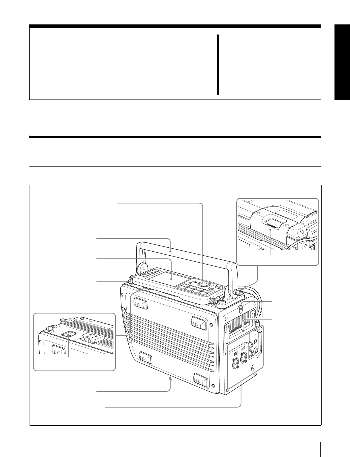
2-1-1 Principal Sections
Control panel (see page 12)
See 3-1-2 “Using the Control Panel
Extension Cable” (page 23) for more
information about using the control
panel apart from the recorder.
6 Top handle
Parts
Chapter
2
Display (see page 14)
5 Lock release button
(for control panel)
7 EJECT button
4 Processor connector
Connector panel (see page 16)
1 Cassette insertion slot
2 Tally indicator
3 Side handle
2-1 SRW-1
11
Page 12

a Cassette insertion slot
Insert cassettes.
d Processor connector
Connect the SRPC-1 HD video processor.
For details, see 3-7-2 “Inserting and Ejecting Cassettes”
(page 36).
b Tally indicator
Chapter 2 Names and Functions of Parts
Lights during recording.
Flashes when errors have occurred (see “About Error
Messages” (page 64)) or when warnings have occurred
(see “About Warning Messages” (page 67)).
e Lock release button (for control panel)
When removing the control panel, use this button.
For more information about using this button, see 3-1-2
“Using the Control Panel Extension Cable” (page 23).
f Top handle
Use to carry the SRW-1 or joined SRW-1/SRPC-1.
If you need to remove the top handle from the SRW-1
For more information about the tally indicator operation,
body, use a coin driver, etc. to loosen the four screws.
see “Warning System” (page 70).
g EJECT button
c Side handle
When the top handle is removed, use this handle to join
Pressing this button opens the lid of the cassette insertion
slot, allowing you to take out the inserted cassette.
and separate the SRW-1 and SRPC-1.
2-1-2 Control Panel
1 Menu selection buttons
2 Display
3 KEY INHI switch
4 LIGHT switch
5 ADJUST knob
6 SELECT/ENTER dial
7 BACK button
8 Control panel
connection cable
ANLG
ANLG
SDI
SDI
SDI
SDI
SDI
SDI
SDI
SDI
A/E
4:2:2
A/E
EMP
EMP
EMP
EMP
L R
L R
L R
L R
9
10
11
12
SRW-1
INHI
RECINHI
F
1080
LOCAL
- - -
21:46
HOME
TC
VIDEO
AUDIO
SYSTEM
dB
0
-10
-20
-30
-60
EMP
EMP
EMP
EMP
EMP
EMP
EMP
L R
L R
L R
1
2
3
PLAY LOCK
OOOO
TCR
LTC
INTRPDFEXT-LK KEY
L R
4
EMP
L R
L R
L R
L R
5
6
7
8
00H00M00S00
12.2V REMAIN CH.COND
46min
23.98PsF
qa EJECT button
a Menu selection buttons
Select the menu shown on the display.
HOME button: Displays the HOME screen. The HOME
screen displays audio levels, operating status,
warnings, time data, and other information.
TC button: Displays the TC (timecode) Setup menu (see
pages 41 to 44). This menu allows you to switch
KEY INHI
OFF ON
LIGHT
OFF ON
EJECT STOP PLAY
xZzB
REW F FWD PAUSE
FUNC
mXM
ADJUST
SELECT/ENTER
BACK
REC
9 Tape transport control buttons
0 FUNC button
between LTC and VITC, to switch between DF and
NDF, and to display timecode on an external monitor.
VIDEO button: Displays the VIDEO Setup menu (see
page 45). This menu allows you to make settings
related to video.
AUDIO button: Displays the AUDIO Setup menu (see
page 46). This menu allows you to make settings
related to audio.
12
2-1 SRW-1
Page 13

SYSTEM button: Displays the SYSTEM Setup menu
(see pages 48 to 50). This menu allows you to make
settings related to the entire systems, such as recording
format, power, and test signal output.
See Chapter 4 “Menu Settings” (page 39) for more
information about menus.
b Display
Displays menus, audio levels, warning, operating status,
time data, remaining tape time, and remaining battery
power.
For details, see 2-1-3 “Display” (page 14).
c KEY INHI (inhibit) switch
When the KEY INHI item (see page 49) in the SYSTEM
Setup menu is set to ALL, setting this switch to ON
disables operation buttons, to prevent misoperations due to
accidental button operations.
ON: All operation buttons are disabled.
OFF: During recording, only the STOP button and
PAUSE button are enabled. All buttons are enabled
when the system is not recording.
When the KEY INHI item in the SYSTEM Setup menu is
set to MAP, the operation buttons follow the settings of the
LOCAL KEYMAP item.
d LIGHT switch
The backlight comes on when this is set to ON.
e ADJUST knob
Use to adjust audio levels, etc.
f SELECT/ENTER dial
When a menu is displayed, you can rotate this dial to move
the cursor, and press it to change and confirm settings.
g BACK button
When a menu is displayed, you can press this button to
back up one level in the menu structure.
To start recording, press the button together with the
REC button.
REC button and indicator: Pressing the button together
with the PLAY button starts recording. The indicator
lights during recording.
If you press this button during stop, fast forward, or
rewind or when no cassette is inserted, the SRW-1
enters E-E mode
2)
signals
output from the HD SDI OUT A/B
1)
. In this mode you can monitor E-E
connectors or the MONITOR OUT HD SDI/SD SDI
connectors of the SRPC-1.
1) E-E mode:
A state in which E-E signals can be monitored. Commonly used to monitor
input signals before they are recorded.
2) E-E (electric to electric) signal:
A signal which passes solely through internal circuitry, and not through
pathways in which magnetic conversion takes place, such as magnetic
heads and tapes.
REW (rewind) button and indicator: Pressing the button
rewinds the tape. The indicator lights during
rewinding, and goes out when rewinding completes.
F FWD (fast forward) button and indicator: Pressing
the button fast forwards the tape. The indicator lights
during fast forwarding, and goes out when fast
forwarding completes.
PAUSE button and indicator: Pressing the button pauses
tape transport. The indicator flashes during pause.
To resume tape transport, press the button again.
j FUNC (function) button
Pressing this button together with another button selects
one of the following operations.
STOP button: Puts the SRW-1 into standby off mode.
HOME button: Switches the display at the bottom of the
HOME screen.
k EJECT button and indicator
Pressing the button opens the cover of the cassette
insertion slot so that you can remove a cassette. The
indicator lights during removal.
Chapter 2 Names and Functions of Parts
h Control panel connection cable
Connect to the SRW-1 CTRL PANEL connector.
i Tape transport control buttons
Use these buttons for tape transport operations.
STOP button: Stops tape transport.
Pressing this button with the FUNC button held down
puts the SRW-1 into standby off mode.
Pressing this button while in standby on mode resets
the still timer.
Pressing the button while in standby off mode puts the
SRW-1 into standby on mode.
PLAY button and indicator: Pressing the button starts
playback. The indicator lights during playback.
2-1 SRW-1
13
Page 14

2-1-3 Display
00H00M00S00
This manual refers to the screen shown below as the
HOME screen.
Chapter 2 Names and Functions of Parts
ANLG
dB
0
-10
-20
-30
-60
EMP
L R
1
OOOO
TCR
00H 00M 00S 00F
12.2V REMAIN CH.COND
1 Audio level meters
ANLG
SDI
SDI
SDI
EMP
EMP
EMP
L R
L R
3
4
PLAY LOCK
INTRP
46min
EMP
L R
5
L R
LTC
2
SDI
SDI
EMP
EMP
L R
L R
6
7
DF
EXT-LK KEY
SDI
SDI
EMP
EMP
L R
L R
8
9
1080
23.98PsF
4:2:2
SDI
EMP
L R
10
SRW-1
A/E
EMP
L R
11
INHI
LOCAL
- - -
21:46
A/E
EMP
L R
12
RECINHI
2 Operation status and warnings
When you press the HOME button with the FUNC
button held down, the sections 4 to 7 are united
into a section to display signal formats as shown
below by 9.
12.2V
SYS : 1080 23.98PsF 4:4:4 SQ
PB : 1080 23.98PsF 4:4:4 SQ
MON : 1080 23.98PsF/525 59.94I
F
9 Signal format
3 Time data
4 Status
5 Signal format
6 Channel condition/RF indicator
7 Remaining tape time
8 Battery level/external power supply voltage
a Audio level meters
Display recording audio levels in recording and E-E mode.
Display playback audio levels during playback.
The numbers 1 to 12 at the bottom are the numbers of
audio tracks on the tape.
b Operation status and warnings
Display the operation status of the system and warnings.
The principal information items are as follows.
TCR/TCG/UBR/UBG/CTL: Type of time data being
displayed.
LTC/VITC: When timecode is being displayed, whether
it is LTC or VITC.
1)
INTRP: Indicates that timecode could not be read
accurately, and has been interpolated.
DF/NDF: Whether the system is in DF (drop-frame) or
NDF (non-drop frame) mode.
KEY INHI: The KEY INHI switch is set to ON.
REC INHI: The cassette is record inhibited.
1) VITC (Vertical Interval Time Code):
Timecode that is inserted on two lines in the vertical blanking interval.
This type of timecode can be read even during very slow playback or still
picture playback.
For more information about warnings, see “About
Warning Messages” (page 67).
c Time data
1)
Displays the CTL signal
(tape running time), timecode,
or user bit data, as selected in the menu system.
1) CTL signal:
This is a control signal consisting of a pulse signal recorded longitudinally
on the tape for every frame of video.
d Status
Displays real time and status information.
e Signal format
Displays the format of recording signals.
f Channel condition/RF indicator
During playback, the letters “CH.COND” appear and one
of the three bars (green, yellow, and red) lights to indicate
the playback signal condition.
Green bar: Playback signal quality is good.
Yellow bar: Playback signal quality is degraded, but
playback is possible.
14
2-1 SRW-1
Page 15

Red bar: Playback signal quality is degraded. If this
continues, head cleaning or internal inspection is
needed.
During playback with tracking control, the “CH.COND”
indication in the HOME screen flashes in yellow (see page
60).
During recording, the letters “RF” appear and a green bar
or a red bar lights to indicate the recording signal
condition. Normally the green bar lights. If a recording
problem occurs, the red bar lights.
Green bar: Recording signal quality is good.
Red bar: Recording signal quality is degraded. If this
continues, head cleaning or internal inspection is
needed.
g Remaining tape time
Displays the time remaining on the tape. “Top” is
displayed at the start of the tape, and “End” is displayed at
the end. The time display flashes when the tape is within
three minutes of the end.
h Battery level/external power supply voltage
Displays the current power level of the battery pack. When
the battery pack is fully charged, all seven segments light
up. As the battery pack discharges, the segments go out
from left to right. When the battery pack is almost
exhausted, the voltage indication and the tally indicator
flash, and a warning tone sounds intermittently. When the
battery pack is completely exhausted, the tally indicator
flashes at a higher rate and the warning tone sounds
continuously.
Chapter 2 Names and Functions of Parts
For more information, see “Warning System” (page 70).
When an external power supply is connected, the voltage
of the external power supply is shown. However, the input
voltage to the DC IN connector is not shown in itself.
Rather the voltage actually used by the system is shown
(lower than the input voltage).
For more information about the relation between segments
and battery voltage, see 3-4-4 “Checking the Power and
Voltage” (page 33).
i Signal formats
This section displays the system signal format, playback
signal format, and monitor output signal format in this
order from the top.
2-1 SRW-1
15
Page 16
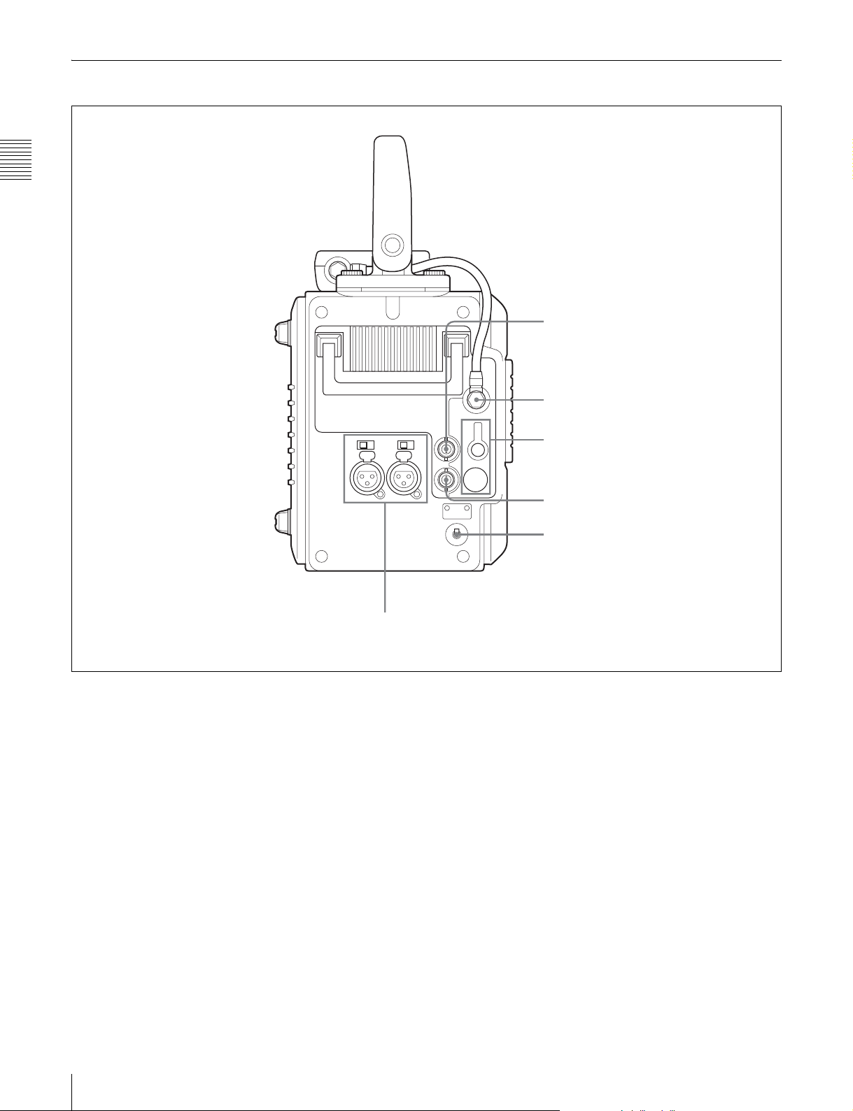
2-1-4 Connector Panel
Chapter 2 Names and Functions of Parts
1 TC IN connector
2 CTRL PANEL connector
3 EARPHONES jack and
LEVEL knob
6 AUDIO INPUT CH-1 and CH-2 connectors and input selection switches
a TC IN (timecode input) connector (BNC type)
Connect to the timecode output connector of an external
device such as a timecode generator or VTR. Use this
connector when locking the internal timecode generator to
external timecode.
b CTRL (control) PANEL connector
Connect the control panel. You can remove the short cable
connected when the SRW-1 is shipped from the factory
and replace it with the supplied extension cable.
For details, see 3-1-2 “Using the Control Panel Extension
Cable” (page 23).
c EARPHONES jack (stereo minijack) and LEVEL
knob
Use this connector to attach earphones or stereo
headphones equipped with a stereo miniplug, for use in
monitoring audio during recording and playback. Adjust
the audio level with the LEVEL knob.
4 TC OUT connector
5 POWER ON/OFF switch
A warning tone is output to the earphones/headphones
when a warning is lit on the control panel display.
d TC OUT (timecode output) connector (BNC type)
Connect to the timecode input connector of an external
device such as a timecode reader or VTR.
The timecode output is determined by the setting of
OTHERS (MAIN) >TC OUT in the TC Setup menu as
follows.
TCG (timecode generator): Timecode generated by the
timecode generator is output, delayed by 1 frame.
(This maintains synchronization with the output
video).
AUTO: During recording (including E-E mode), timecode
generated by the timecode generator is output, delayed
by 1 frame. (This maintains synchronization with the
output video).
During playback, the LTC signal read from the tape is
output.
16
2-1 SRW-1
Page 17

THRU: Timecode input to the TC IN connector is through
output.
TCG (No Delay): Timecode generated by the timecode
generator is output, with no delay. (The timecode is
out of synchronization with the output video, being 1
frame in advance of the video.) Select this setting
when you want to synchronize other devices, using the
timecode generator of this unit as the master.
e POWER ON/OFF switch
When the SRPC-1 power is on, push this switch up to the
ON side to power the SRW-1 on. To power the SRW-1 off,
push the switch down to the OFF side.
Normally leave this switch on the ON side since the SRW1 is powered on and off automatically by the SRPC-1
POWER ON/OFF switch.
f AUDIO INPUT CH-1 and CH-2 (analog audio
input channels 1 and 2) connectors (XLR 3-pin,
female) and input selection switches
These connectors allow up to two analog audio signals to
be input from microphones and other external audio
devices.
Set the input selection switches as follows, depending on
the type and level of the input audio.
LINE: For line input
MIC: For microphone input
+48V ON: For input from microphones with external
power supply
Chapter 2 Names and Functions of Parts
2-1 SRW-1
17
Page 18

2-2 SRPC-1
When optional HKSR-101 installed
Chapter 2 Names and Functions of Parts
1 Recorder connector
2 Lock lever
3 Release knob
4 B attery attachment
section
5 AUDIO INPUT CH-3 and
CH-4 connectors and input
selection switches
6 MONITOR OUT L and R
connectors
7 AES/EBU INPUT CH7/8 and CH9/10
connectors
8 AES/EBU OUTPUT CH1-12 connector
w; CAMERA connector
9 Assist lever
0 EARPHONES jack and
LEVEL knob
qa HD SDI OUT A and B
connectors
qs HD SDI IN A and B connectors
qd MONITOR OUT HD SDI
and SD SDI connectors
qf REF IN HD and SD connectors
qg POWER ON/OFF switch
qh REMOTE IN connector
qj CAMERA REMOTE IN
connector
qk EXT DC SELECT switch
ql DC IN connector
a Recorder connector
Connect the SRW-1 HD Portable Digital Recorder.
b Lock lever
After joining the SRW-1 and SRPC-1, rotate this lever to
lock the joint.
c Release knob
When separating the joined SRW-1 and SRPC-1, rotate the
assist lever while pulling out this knob.
Note
Once you have joined the SRW-1 and SRPC-1, do not pull
out the release knob except when you want to detach the
SRW-1 from the SRPC-1 because doing so results in
separation of these units.
d Battery attachment section
Attach a BP-GL95/IL75 Battery Pack or AC-DN10/DN2B
AC Adaptor.
18
2-2 SRPC-1
For details, see 3-4 “Power Supply Preparations” (page
32).
e AUDIO INPUT CH-3 and CH-4 (analog audio
input channels 3 and 4) connectors (XLR 3-pin,
female) and input selection switches
These connectors allow up to two analog audio signals to
be input.
Set the input selection switches as follows, depending on
the type and level of the input audio.
LINE: For line input
MIC: For microphone input
+48V ON: For input from microphones with external
power supply
f MONITOR OUT (audio monitor output) L and R
connectors (XLR 3-pin, male)
Output audio monitor signals.
Page 19

g AES/EBU INPUT CH7/8 and CH9/10 (digital
audio input channels 7/8 and 9/10) connectors
(BNC type)
These connectors allow up to four AES/EBU format
digital audio signals to be input.
Note
The AES/EBU signals must be locked to the video signal.
h AES/EBU OUTPUT CH1-12 (digital audio output
channels 1 to 12) connector (D-sub 15-pin)
Outputs up to 12 channels of AES/EBU format digital
audio signals.
This connector is specially designed for this system. For
details, refer to the Maintenance Manual Volume 1.
i Assist lever
Use this lever when joining or separating the SRW-1 and
SRPC-1.
n REF IN (reference signal input) HD and SD
connectors (BNC type)
Input a reference video signal with the correct frame
frequency.
HD connector: As an HD reference video signal, input a
tri-level bipolar sync signal.
SD connector: As an SD reference video signal, input a
video signal with a chroma burst signal (VBS) or black
and white video signal (VS).
When carrying out recording, set REFERENCE >MODE
in the SYSTEM Setup menu to “Input” so that the system
is synchronized with the input video signal.
To record the input video signal in synchronization with an
HD reference video signal, input an HD reference video
signal of the same phase as the input video signal.
Note
When using a reference video signal, its field frequency
must correspond to the system frame frequency set with
FORMAT >FRAME in the SYSTEM Setup menu.
Chapter 2 Names and Functions of Parts
j EARPHONES jack (stereo minijack) and LEVEL
knob
Use this connector to attach earphones or stereo
headphones equipped with a stereo miniplug, for use in
monitoring audio during recording and playback. Adjust
the audio level with the LEVEL knob.
A warning tone is output to the earphones/headphones
when a warning is lit on the control panel display.
k HD SDI OUT A and B connectors (BNC type)
Output HD SDI video and audio signals.
When the signal format is 4:2:2, the signals are output
from the “A” connector.
l HD SDI IN A and B connectors (BNC type)
Input HD SDI video and audio signals.
When the signal format is 4:2:2, input the signals to the
“A” connector.
m MONITOR OUT (video monitor output) HD SDI
and SD SDI connectors (BNC type)
Output SDI video and audio signals for monitoring.
HD SDI connector: Outputs HD SDI video and audio
signals for monitoring.
The PD(MON) item in the VIDEO Setup menu (see
page 45) allows you to select whether pull-down
conversion of this output is performed or not.
SD SDI connector: Outputs SD SDI video and audio
signals for monitoring.
Regardless of signal format settings, these connectors
always output signals in 4:2:2 format.
VTR operating status and timecode can be superimposed
on the output (see the CHAR(MON) item in the TC Setup
menu (page 43)).
o POWER ON/OFF switch
Powers the SRPC-1 on when pushed up to the ON side. To
power the SRPC-1 off, push the switch down to the OFF
side.
When the SRW-1 is joined to the SRPC-1, this switch
powers both the SRW-1 and SRPC-1 on and off.
p REMOTE IN (remote control input) connector (9-
pin)
Reserved for future expansion. Currently not used.
q CAMERA REMOTE IN (remote control input)
connector (8-pin)
When the optional HKSR-101 Optical Interface Unit is
installed, you can connect an RM-B750/B150 Remote
Control Unit to this connector.
r EXT DC SELECT (external power selection)
switch
Select the operating mode when an external power supply
is connected.
AUTO: Normally use the external power supply
connected to the DC IN connector, but when its
voltage declines, automatically switch to the power
supply attached to the battery attachment section.
EXT (external): Always use only the external power
supply connected to the DC IN connector.
s DC IN connector (XLR 4-pin, male)
When using the optional AC-550/DN2B/DN10 AC
Adaptor to connect to an AC power source, connect the
DC power cord of the adaptor to this connector.
Use only the DC power cord supplied with the AC adapter.
2-2 SRPC-1
19
Page 20

t CAMERA connector (optical-fiber connector)
(when HKSR-101 installed)
Connect the HDC-F950 HD Color Video Camera by FC2PD50/PD250 Optical-Fiber Cable (optional).
A single optical-fiber cable can send and receive audio and
control signals multiplexed into video signals.
Chapter 2 Names and Functions of Parts
Refer to the HKSR-101 Installation Manual for
information about installing the HKSR-101.
Notes
• Power cannot be supplied from this unit to a camera over
optical-fiber cable.
• Communications errors can occur if dust accumulates on
the surface of the connector of the optical-fiber cable.
Always clean the CAMERA connector before use.
Whenever the CAMERA connector is not in use, always
cover it with the cap supplied with the HKSR-101.
Refer to the HKSR-101 Installation Manual for
information about cleaning the optical-fiber connector.
20
2-2 SRPC-1
Page 21

3-1 Assembly
Preparations
Chapter
3
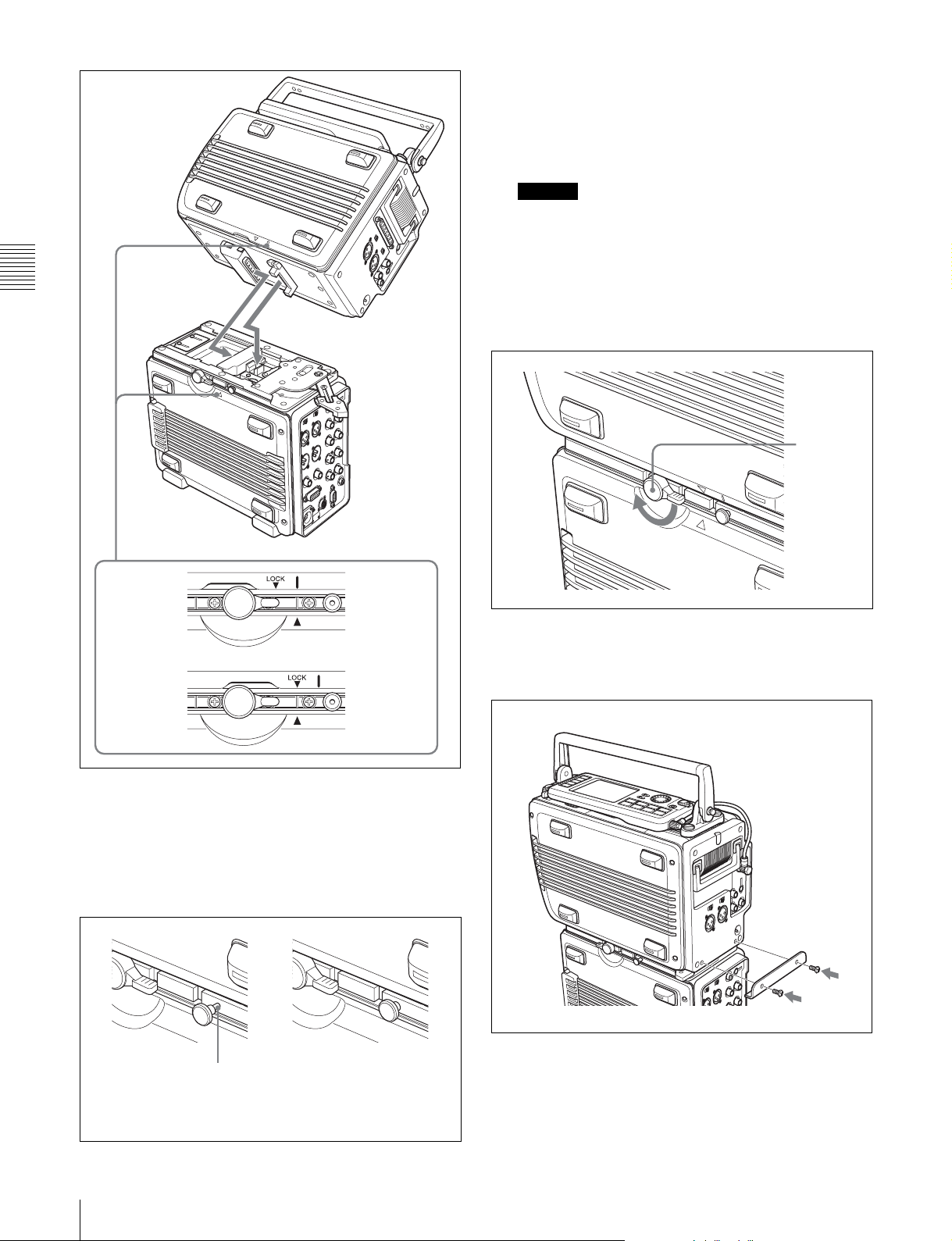
3-1-1 Joining the SRW-1 and SRPC-1
When using the optional HKSR-101 Optical Interface
Unit, refer to the HKSR-101 Installation Manual.
To mount the SRW-1 on the SRPC-1, proceed as follows.
1
Place the SRPC-1 on a flat, stable surface of a bench,
table or the like.
2
Rotate the lock lever counterclockwise (see the figure
for step 3) until it is almost horizontal.
3
Move the assist lever to the unlock position (rotate it in
the direction of the arrow as far as it will go).
Lock lever
Assist lever
Note
If the top handle is detached from the SRW-1, grasp
the side handle with one hand and mount the SRW-1
while supporting it with your other hand.
4
Grasp the top handle of the SRW-1, align the mark on
the SRW-1 with the v mark on the SRPC-1 (see “To
release” in the following figure), and then place the
SRW-1 on the top of the SRPC-1.
3-1 Assembly
21
Page 22
Next, by attempting to rotate the assist lever again to
the lock position, check to be sure that now the assist
lever will not go beyond half the way and that the
SRW-1 keeps joined to the SRPC-1.
Caution
The SRW-1 and SRPC-1 are not properly joined
unless the release knob is all the way in. They may
come apart, or the SRW-1 may fall off.
6
Chapter 3 Preparations
Rotate the lock lever on the side panel of the SRPC-1
in the direction of the arrow to lock the joint between
the SRPC-1 and SRW-1.
Lock lever
To release
To lock
5
Rotate the assist lever back to its original (lock)
SRW-1 side
SRPC-1 side
SRW-1 side
SRPC-1 side
position to align the LOCK V mark on the SRW-1
with the v mark on the SRPC-1. (See “To lock” in the
previous figure.)
When you do this, check to be sure that the release
knob (see the following figure) is all the way in.
7
Remove the two screws from the holes on the SRW-1,
and use these two screws to mount the supplied assist
lever holding bracket on the SRW-1.
Assist lever
holding bracket
Screws (×2)
22
Release knob is
not all the way in.
3-1 Assembly
This part is visible.
Release knob is
all the way in.
To detach the SRW-1 from the SRPC-1
1
Place the joined SRPC-1 and SRW-1 on a flat, stable
surface of a bench, table or the like.
Page 23
2
Unscrew the assist lever holding bracket from the
body of the SRW-1.
3
Rotate the lock lever on the side panel of the SRPC-1
in the direction of the arrow to unlock the joint
between the SRPC-1 and SRW-1.
Lock lever
4
While pulling out the release knob on the side panel of
the SRPC-1, rotate the assist lever in the direction of
arrow and then slide the SRW-1.
3-1-2 Using the Control Panel
Extension Cable
When they are shipped from the factory, the control panel
and SRW-1 are connected by a short cable. You can
replace this cable with the supplied extension cable, which
allows you to use the control panel apart from the SRW-1.
Proceed as follows.
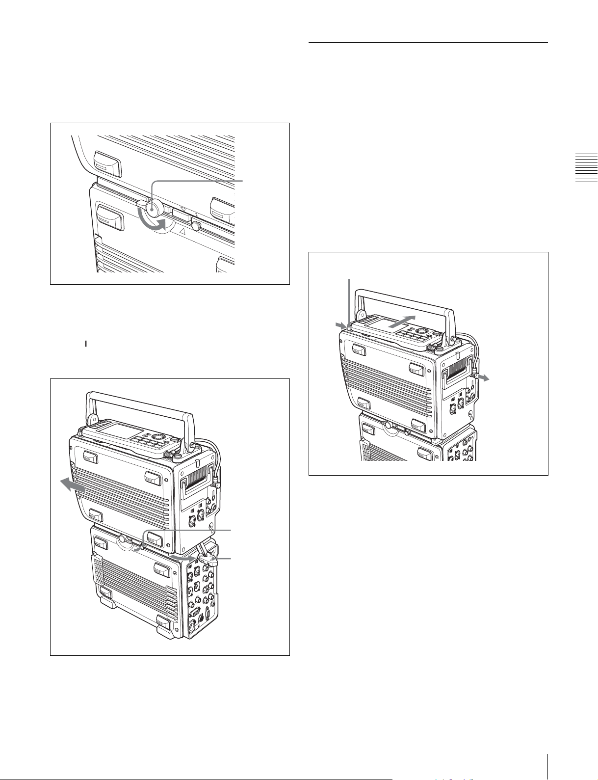
1
Disconnect the short cable from the CTRL PANEL
connector on the SRW-1. (See the following figure.)
2
While pressing the lock release button next to the
control panel, slide the control panel in the direction of
the arrow in the figure to separate the control panel
from the SRW-1 body.
Lock release button (for control panel)
Chapter 3 Preparations
The mark on the SRW-1 is aligned with the v mark
on the SRPC-1. (See “To release” in the figure on
page 22.)
Release knob
Assist lever
Remove cable
3
Remove the cable from the control panel and replace it
with the extension cable.
4
Connect the extension cable to the CTRL PANEL
connector on the SRW-1.
5
Lift the SRW-1 off the SRPC-1.
6
Move the assist lever to the lock position.
3-1 Assembly
23
Page 24

almost no slack, then fix the cable in groove A and
groove B. (See figure in step 2.)
4
While avoiding the cassette insertion slot, fix the slack
part of the rest of the cable in the clamp.
Cassette insertion slot
Chapter 3 Preparations
Clamp
To secure the extension cable with the cable
clamp
You can attach the cable clamp supplied with the SRW-1
to secure part of the extension cable. Proceed as follows.
1
Remove the two screws from the SRW-1. (See
following figure.)
2
Attach the supplied cable clamp to the SRW-1 using
the screws removed in step 1.
Groove A
Cable clamp
Screws
Groove B
24
3
Gently pull the part of the cable closest to the control
panel in the direction of the arrow so that there is
3-1 Assembly
Page 25

3-2 Connections
This section explains how to make connections for
recording and playback.
3-2-1 Connections for Recording
The following figures show connections between this unit
and a camera or camcorder.
About monitor connections, see the figures in 3-2-2
“Connections for Playback” (page 27).
To connect the HDW-F900 to record 4:2:2 signals
HD SDI OUT
HDW-F900 HD multi-format
camcorder (with HDCA-901)
To connect the HDC-F950 to record RGB 4:4:4 signals
Chapter 3 Preparations
HD SDI IN A
SRW-1 + SRPC-1
HDC-F950 multi-format
camera system
LINK A/B OUT HD SDI IN A
HD SDI IN B
SRW-1 + SRPC-1
3-2 Connections
25
Page 26

To record the output of 2 camera systems as 4:2:2 DUAL STREAM
Reference
signals
GENLOCK IN
Chapter 3 Preparations
LINK A OUT
HDC-F950 multi-format
camera system
HD SDI IN A
HD SDI IN B
SRW-1 + SRPC-1
GENLOCK IN
HD SDI OUT
HDW-F900 HD multi-format
camcorder (with HDCA-901)
Note
Synchronize the two cameras.
To record 4:2:2 or 4:4:4 signals using optical-fiber cable
26
CCU CAMERA
FC2-PD50/PD250 Optical-Fiber Cable (optional).
HDC-F950 multi-format
camera system
SRW-1 + SRPC-1 + HKSR-101 (optional)
Note
Set VIDEO I/O >VA INPUT in the VIDEO Setup menu to CAM(Optical).
3-2 Connections
Page 27

3-2-2 Connections for Playback
To connect an HD monitor
HD video input
MONITOR OUT HD SDI
SRW-1 + SRPC-1
To connect an NTSC monitor
To connect an HD monitor supporting RGB
4:4:4 (Dual Link)
HD monitor
BVM-F24 HD monitor
Chapter 3 Preparations
HD SDI
LINK A IN LINK B IN
HD SDI OUT A
HD SDI OUT B
SRW-1 + SRPC-1
NTSC monitor
SRW-1 + SRPC-1
SD video input
SD SDI
MONITOR OUT SD SDI
3-2 Connections
27
Page 28

3-3 About Reference Sync Signals
This section explains how to select reference signals for
video output signals.
3-3-1 Reference Signals for Video Output Signals
The video signals output from this system are
synchronized as shown below, depending on the operating
Chapter 3 Preparations
Start
SYSTEM Setup >
REFERENCE >
MODE setting?
SYSTEM Setup >
REFERENCE >
EXTERNAL setting?
state of the system, SYSTEM Setup menu settings (see
page 48), and input signals.
Input
External
HD&SDSD
Signals input to HD SDI
IN A/B connectors?
No
Sync to signals
input to HD SDI IN
A/B connectors
Yes
Signals with correct
frequency input to REF
IN SD connector?
No
Sync to reference
video signals input
to REF IN SD
connector
Yes
HD
Signals with correct
frequency input to REF
IN HD connector?
No
Sync to reference
video signals input
to REF IN HD
connector
No external sync (internal sync)
Yes
Signals with correct
frequency input to
REF IN HD and SD
connectors?
No
Sync to reference
video signals input
to REF IN HD and
SD connectors
Yes
28
3-3 About Reference Sync Signals
Page 29

3-3-2 Connecting Reference Signals (Examples for When External Sync Is
Required)
Connect reference signals as explained below, depending
on how you want to use the system.
Connections to record signals from cameras, switchers, signal generators, etc.
In the SYSTEM Setup menu, set REFERENCE >MODE
to “Input” (see page 48), and then connect as shown below.
HD SDI IN A/B
(A only or A/B)
In the SYSTEM Setup menu, set
REFERENCE >MODE to “Input.”
SRW-1 + SRPC-1
Connections to record using optical-fiber cable
To record using an optical-fiber connection between this
unit and the HDC-F950 camera, with the optional HKSR101 installed in the SRPC-1, the first step is to synchronize
by supplying reference signals from this unit to the HDCF950 over the optical-fiber cable. Next, output signals
from the synchronized HDC-F950 are input to this unit,
replacing the reference signals of this unit.
If you do not want to input external reference signals to
this unit, set REFERENCE >MODE (see page 48) in the
SYSTEM Setup menu to “Input”.
Reference signals
Camera, switcher, signal
generator, etc.
HD SDI OUT A/B
(A only or A/B)
REF IN, GENLOCK IN
When you need to input external reference
signals to this unit
Set REFERENCE >MODE in the SYSTEM Setup menu
to “External”, and set REFERENCE >EXTERNAL to the
appropriate value for the reference signals that you are
using (see page 48).
If you want to input an HD tri-level sync signal to the REF
IN HD connector, set REFERENCE >EXTERNAL to
“HD” and make the connections shown below.
Chapter 3 Preparations
HDC-F950 multi-format
camera system
CCU CAMERA
FC2-PD50/PD250 Optical-Fiber
Cable (optional).
SRW-1 + SRPC-1
+ HKSR-101 (optional)
REF IN HD
3-3 About Reference Sync Signals
Reference signals
In the SYSTEM Setup menu,
set REFERENCE
>EXTERNAL to “HD”.
29
Page 30

Connections to input playback signals to an external HD VTR
In the SYSTEM Setup menu, set REFERENCE >MODE
to “External,” set REFERENCE >EXTERNAL to “HD”
(see page 48), and then connect as shown below.
Reference signals
Chapter 3 Preparations
HD SDI OUT A/B
REF IN HD
In the SYSTEM Setup menu, set
REFERENCE >MODE to
“External,” and set REFERENCE
>EXTERNAL to “HD.”
SRW-1 + SRPC-1
(A only or A/B)
Note
When you make the menu settings described at left, always
input an HD tri-level sync signal to the REF IN HD
connector.
HD SDI INPUT A/B
(A only or A/B)
SRW-5000 HD Digital
Videocassette Recorder
Connections to output playback signals from this system (synchronized with both
23.98PsF and 59.94i)
When the frame frequency is 23.98PsF, you can
synchronize pulldown output signals and downconvert
output signals to a 59.94i reference signal input to the REF
IN SD connector.
In the SYSTEM Setup menu, set REFERENCE >MODE
to “External,” set REFERENCE >EXTERNAL to
“HD&SD”(see page 48), and then connect as shown
below.
Reference signal input
(HD 23.98PsF)
Synchronized
Reference signal input
(SD 59.94i)
REF IN HD
REF IN SD
SRW-1 + SRPC-1
In the SYSTEM Setup menu, set
REFERENCE >MODE to
“External”, and set REFERENCE
>EXTERNAL to “HD&SD”.
HD SDI OUT A/B
(A only, or A/B)
MONITOR OUT HD SDI
MONITOR OUT SD SDI
SD monitor
Notes
• These settings are valid only when the frame frequency
of this system is 23.98PsF.
• When you make the settings described at left, always
input the appropriate reference signals to the REF IN HD
and REF IN SD connectors. These reference signals
must be synchronized.
A warning message appears if they are not synchronized.
(HD 23.98PsF)
HD SDI INPUT A/B
(A only, or A/B)
SRW-5000 HD Digital Videocassette
Recorder
(HD 23.98PsF or 59.94i) (according to
the setting of PD(MON) in the Video
Setup menu)
HD monitor
(SD 59.94i)
30
3-3 About Reference Sync Signals
Page 31

Connections to output playback signals from this system (synchronized with SD59.94i or
SD50i)
When the frame frequency is 29.97 Hz/25 Hz, you can use
a VBS reference signal input to the REF IN SD connector
as the playback reference signal.
In the SYSTEM Setup menu, set REFERENCE >MODE
to “External,” set REFERENCE >EXTERNAL to “SD”
(see page 48), and then connect as shown below.
Notes
• These settings are valid only when the frame frequency
of this system is 29.97 Hz/25 Hz.
• Do not connect a reference signal to the REF IN HD
connector.
• Input a VBS signal conforming to the operating frame
frequency to the REF IN SD connector.
VBS reference signal
(SD 59-94i or 50i)
REF IN SD
SRW-1 + SRPC-1
In the SYSTEM Setup menu, set
REFERENCE >MODE to “External”, and set
REFERENCE >EXTERNAL to “SD”.
(HD 23.98PsF)
HD SDI OUT A/B
(A only, or A/B)
MONITOR OUT HD SDI
MONITOR OUT SD SDI
HD SDI INPUT A/B
(A only, or A/B)
SRW-5000 HD Digital Videocassette
Recorder
HD monitor
Chapter 3 Preparations
SD monitor
3-3 About Reference Sync Signals
31
Page 32

3-4 Power Supply
Preparations
This system can be used with a battery pack or AC power.
3-4-1 Using a Battery Pack
Arrow mark
The battery pack usable with this system is the BP-GL95/
Chapter 3 Preparations
IL75.
Before use, charge the battery pack with the special battery
charger.
Detach the battery pack if you will not be using the system
for an extended period of time.
Refer to the operation manual of the battery charger for
more information about how to charge battery packs.
To detach a battery pack
While pressing the lock release button on the battery
attachment section, slide the battery pack in the direction
opposite to the direction in which you attached it.
Line on SRPC-1
To attach a battery pack
1
While pressing in the lock release button on the battery
attachment section of SRPC-1, slide the battery
connector cover to remove it. (See the figure in the
next item, “To detach a battery pack”.)
2
Align the line on the battery attachment section of the
SRPC-1 with the line on the side of the battery pack.
Battery pack
Note
Compared to equipment such as the HDW-F900
camcorder, the battery attachment section of the SRPC-1 is
closer to the ground.
For this reason, you should be careful when moving the
system with a battery pack attached as shown in the above
figure, to prevent the bottom of the battery pack from
striking the ground, which may cause it to come off.
Lock release button
3
Slide the battery pack down until its LOCK arrow
points at the matching line on the SRPC-1.
32
3-4 Power Supply Preparations
Align these lines.
3-4-2 Using AC Power
The AC adaptors usable with this system are the AC-550
and the AC-DN10/DN2B.
Both adaptors are supplied with DC power cords, which
are connected to the DC IN connector on the rear panel of
the SRPC-1.
The AC-DN10/DN2B can also be attached to the battery
attachment section of the SRPC-1.
To attach the AC-DN10/DN2B
Refer to “To attach a battery pack” (page 32) and attach in
the same way.
Page 33

Note
If you are attaching an AC adaptor to the battery
attachment section, set BATTERY >BATT TYPE in the
SYSTEM Setup menu to “AC Adapter” (see page 50). If
you are connecting an AC adaptor to the DC IN connector,
set BATTERY >DC IN TYPE in the SYSTEM Setup
menu to “AC Adapter”.
3-4-3 Powering On and Off
3-4-4 Checking the Power and
Voltag e
To check the type of power being used
A battery mark appears in the lower left of the control
panel display when power is being supplied from the
battery attachment section.
A power plug mark appears when an AC adaptor is
selected as power supply.
To power on
To power the SRW-1 and SRPC-1 on, proced as follows.
1
If you are using an AC adaptor, turn the AC adaptor
on.
2
Turn the SRPC-1 POWER ON/OFF switch to ON.
The SRW-1 is powered on automatically when its
POWER ON/OFF switch is set to ON.
Powering on when the optional HKSR-101 is
installed
If you have installed the optional HKSR-101 in SRPC-1 to
connect this unit to a HDC-F950 camera via optical-fiber
cable, power on in the order this unit on t HDC-F950 on.
Signal transmission may not be conducted properly if this
power-on order is not observed.
To power off
Note
To protect tapes, do not power the SRW-1 off with a
cassette loaded. Always eject the cassette first, and then
use the following procedure to power the system off.
1
Turn the SRPC-1 POWER ON/OFF switch to OFF.
If the SRW-1 POWER ON/OFF switch is set to ON,
the SRW-1 is also powered off automatically.
2
If you are using an AC adaptor, turn the AC adaptor
off.
12.2V
Note that this mark does not reflect the actual type of
power being used, but reflects the settings of the following
menu items.
• SYSTEM Setup >BATTERY >BATT TYPE
• SYSTEM Setup >BATTERY >DCIN TYPE
To check the remaining battery power
You can check the remaining battery power with the
battery level display.
12.2V
As the battery pack discharges, the segments go out from
left to right. When the battery pack is almost exhausted
(NEAR END), the voltage indication and the tally
indicator start to flash, and an intermittent warning tone
sounds in the headphones. When the battery pack is
completely exhausted (END), the corresponding warning
indication lights, the tally indicator starts to flash at a
higher rate, and the headphones warning tone sounds
continuously.
The BATTERY item in the SYSTEM Setup menu (see
page 50) allows you to set the battery voltages for which
NEAR END and END warnings are issued.
Chapter 3 Preparations
If you should ever power off with a cassette still loaded in
the SRW-1, the unit does not power off immediately. To
protect the tape, the unit powers off after first returning the
tape to the unthread position.
3-4 Power Supply Preparations
33
Page 34

3-5 Display Settings
3-6 Superimposed Text
Information
If the display is hard to see because of low light conditions,
you can set the LIGHT switch to ON to turn on the
backlight.
LIGHT switch
ANLG
ANLG
SDI
SDI
SDI
SDI
SDI
SDI
SDI
SDI
A/E
Chapter 3 Preparations
dB
0
-10
HOME
-20
-30
-60
EMP
TC
L R
1
OOOO
VIDEO
TCR
AUDIO
00H00M00S00
SYSTEM
12.2V REMAIN CH.COND
EMP
EMP
EMP
EMP
EMP
L R
L R
L R
L R
L R
2
3
4
5
6
PLAY LOCK
LTC
INTRPDFEXT-LK KEY
46min
A/E
KEY INHI
EMP
EMP
L R
L R
7
8
1080
23.98PsF
4:2:2
OFF ON
EMP
EMP
EMP
EMP
L R
L R
11
12
INHI
RECINHI
F
LOCAL
- - -
21:46
LIGHT
OFF ON
EJECT STOP PLAY
xZzB
REW F FWD PAUSE
FUNC
mXM
L R
L R
9
10
SRW-1
SELECT/ENTER
BACK
ADJUST
REC
To make the backlight brighter
Select LCD >BRIGHT in the SYSTEM Setup menu (see
page 49) and adjust the brightness (0 to 31) in the
Backlight Brightness window.
Timecode, operating modes, warning/error messages, and
other text information can be superimposed on the video
signals output from the MONITOR OUT HD SDI and SD
SDI connectors of the SRPC-1.
Use the TC Setup menu to specify whether to superimpose
this information, and to select the position and type of the
superimposed text. Select the menu item CHAR(MON)
(see page 43) to make settings for text information output
from the MONITOR OUT HD SDI connector, and select
the menu item CHAR(SD) (see page 44) to make settings
for text information output from the MONITOR OUT SD
SDI connector.
Information displayed
1Monitor output format
Time data
2Tape remaining
To turn the backlight off after a specified
interval
Select LCD >LIGHT OFF in the SYSTEM Setup menu
(see page 49) and select the time that the backlight should
remain on (5 seconds to 5 minutes) in the Backlight Off
Timer window.
To keep the backlight on, select “Disable.”
To display a screen saver after a specified
interval
Select LCD >SAVER in the SYSTEM Setup menu (see
page 49) and select the time after which the screen saver
should appear (1 minute to 1 hour) in the Screen Saver
window.
Select “Disable” if you do not want to display a screen
saver.
See 4-1“Basic Menu Operations” (page 39) for more
information about menu operations.
1080 23 . 98PsF (
TCR.12:34.56.01*
PLAY LOCK
4Operating
mode of
this system
3Time data type
6Timecode generator drop-frame
A)
R1
13.5V
8Battery voltage
7VITC field mark
mark
5Timecode reader drop-frame mark
a Monitor output format
Displays the format of each video signal output from the
MON OUT HD SDI connector and the MON OUT SD SDI
connector. (This is not the system format.)
The display disappears after a few seconds whenever the
unit is in any of the following states.
• When the unit is powered on after changing the system
format
• Immediately after pressing the REC button to enter E-E
mode
• Immediately after changing the VIDEO >MON SEL(x2)
>TYPE setting to “Link A” or “Link B”
• Immediately after setting VIDEO >DC >PD(MON) to
“AUTO” or “THRU” (only when the operating frame
frequency is 23.98PsF)
34
3-5 Display Settings / 3-6 Superimposed Text Information
Page 35

b Tape remaining
The remaining tape capacity is displayed as follows.
Display of remaining tape time when it is 23 minutes or less
TCR.23:59:40:18 R23
Display of remaining tape time when it is 5 minutes or less
TCR.23:59:40:18 R5
c Time data type
Display Meaning
CTL CTL counter data
TCR LTC reader timecode data
UBR LTC reader user bit data
TCR. VITC reader timecode data
UBR. VITC reader user bit data
TCG Timecode generator timecode data
UBG Timecode generator user bit data
When timecode and user bit data cannot be read correctly,
asterisks (*) are displayed in these blocks, for example as
“T*R”, “U*R”, “T*R.”, and “U*R.”.
e Timecode reader drop-frame mark (525-line mode
only)
“ . ”: Drop-frame mode
“ : ”: Non-drop frame mode
f Timecode generator drop-frame mark (525-line
mode only)
“ . ”: Drop-frame mode
“ : ”: Non-drop frame mode
g VITC field mark
“ ” (blank): Displaying odd field
“ * ”: Displaying even field
h Battery voltage
Displays the battery or AC power voltage.
To display warning/error messages
Set TC Setup menu items CHAR(MON) > MODE and
CHAR(SD) > MODE to something other than “TIME”.
Next, to display both warnings and error messages, set
WARN to “W+E”. To display error messages only set
WARN to “ERR”.
The first 16 characters of messages are displayed as
flashing characters on the second line.
Chapter 3 Preparations
d Operating mode
The information displayed is divided as shown in the
following figure into blocks A and B.
Block A: Operating mode
Block B: Servo lock state or tape speed
AB
The following modes are shown in the operating mode
display.
“SYSTEM READY”
“CASSETTE OUT”
“STANDBY OFF”
“REC”
“REC LOCK”
“REC PAUSE”
“PLAY”
“PLAY LOCK”
“PLAY PAUSE”
“F.FWD”
“REW”
“TAPE UNTHREAD”
“STOP”
“STANDBY ON”
TCR.23:59:40:18
NO EXTERNAL REFE
The first 16 characters of a warning/error message
See page 67 for more information about warning
messages, and see page 64 for more information about
error messages.
When two or more warnings or error messages are issued
at the same time, each message is repeated twice in
flashing characters.
When there are no warnings or error messages, the
information selected with the CHAR(MON) > MODE and
CHAR(SD) > MODE menu items is displayed as flashing
characters on the second line.
To change the position of superimposed
text
You can move the position of superimposed text in 16
steps horizontally (0 to 15) and 24 steps vertically (0 to
23).
To set the values, use CHAR(MON) > HPOS/VPOS or
CHAR(SD) > HPOS/VPOS in the TC Setup menu.
3-6 Superimposed Text Information
35
Page 36

To insert cassettes
3-7 Handling Cassettes
1
3-7-1 Usable Cassettes
This system uses 1/2-inch width HDCAM-SR S-size
cassettes.
The maximum recording times are as follows.
System frequency Maximum recording time
Chapter 3 Preparations
29.97 Hz 40 minutes (20 minutes for
double-speed recording)
25 Hz 48 minutes
23.98 Hz/24Hz 50 minutes (25 minutes for
double-speed recording)
4
3
Note
Use this unit (SRW-1) or a SRW-5000/5500 unit to rewind
tapes. Do not use cassettes which have been rewound by
other units or by rewinders.
Storage of cassettes
Store your cassettes at room temperature and normal
humidity.
3-7-2 Inserting and Ejecting
Cassettes
Check to be sure that the system is powered on before
inserting and ejecting cassettes.
Note
To protect tapes, do not power the SRW-1 off with a
cassette loaded. Always eject the cassette first, and then
use the following procedure to power the system off.
2
1
Set the SRW-1 and SRPC-1 POWER ON/OFF
switches to ON.
2
Press the EJECT button.
The cover of the cassette insertion slot opens.
3
Check the following, and then insert the cassette.
• There is no slack in the tape. (If there is slack in the
tape, see “Removing slack in the tape”.)
• There is no error message in the display (see page
64).
36
3-7 Handling Cassettes
4
Press the cover of the cassette insertion slot to close it.
The tape is wound on the drum.
If “VTR 007F: HUMID ERROR” appears in the
display
Condensation was detected.
See “Condensation” (page 61) for the steps to take.
Page 37

Removing slack in the tape
Carefully rotate one of the reels in the direction of the
arrow until it stops.
3-7-3 Preventing Accidental Erasure
To prevent accidental erasure of material recorded on a
tape, push in the record-protect plug.
Push in the record-protect plug.
To restore the tape for recording,
return the plug to its original position.
Chapter 3 Preparations
To eject cassettes
With the system powered on, press the EJECT button on
the control panel.
The tape is unthreaded and the cassette is automatically
ejected. This operation takes a few seconds.
To cancel the ejection before it is finished, press any of the
other operation buttons before the cassette is completely
ejected. The cassette ejection operation is canceled and the
operation corresponding to the button you pressed starts.
To remove a cassette with the system powered
off
Proceed as follows if you need to remove a cassette with
the SRW-1 powered off, because the battery pack is
exhausted or for some other reason.
Cassette insertion slot
1 Power off the SRW-1 and
SRPC-1.
2 Open the rubber cover by
pressing the depression on the
left side of the cover with your
finger, pushing it toward the
right, and lifting up the left edge
of the cover.
3 Use a screwdriver to press in the
screw inside, and rotate the
screw in the clockwise direction
until the cassette insertion slot
cover opens.
When a cassette with the plug in this position is inserted
into the recorder, the REC INHI indicator lights up on the
control panel display and recording will not start, even if
you press the REC and PLAY buttons.
To restore the tape for recording, return the plug to its
original position.
There is no need to return the screw to its original position
after you remove the cassette. Normal operation resumes
again the next time you power the system on.
For the method of ejecting the cassette after a slack error
(forcible eject), refer to the Maintenance Manual.
3-7 Handling Cassettes
37
Page 38

Chapter 3 Preparations
38
3-7 Handling Cassettes
Page 39

Menu Settings
Chapter
4
4-1 Basic Menu
Operations
4-1-1 Displaying Menus
The menu system of the joined SRW-1/SRPC-1 consists of
four setup menus.
• TC Setup menu (see page 41)
• VIDEO Setup menu (see page 45)
• AUDIO Setup menu (see page 46)
• SYSTEM Setup menu (see page 48)
To display menus
Press the menu button (TC, VIDEO, AUDIO, or
SYSTEM) corresponding to the menu that you want to
display.
VIDEO button
HOME button
TC button
SELECT/ENTER dial
BACK button
4-1-2 Changing Menu Settings
1
Rotate the SELECT/ENTER dial to move the cursor to
the target item.
TC Setup
TIMER SEL
TIMER RESET
TIMER PRESET
TCR SEL
TCG MODE
REGEN SRC
RUN MODE
Cursor
2
Press the SELECT/ENTER dial.
TCG SET(MAIN)
OTHERS (MAIN)
PD TC
CHAR(MON)
CHAR (SD)
SRW-1
A submenu window opens for the selected item. If the
selected item is a command, the command is executed.
TC
LTC
PRST
INT L
R RUN
TCR
Submenu window
00:00:00:00CASS OUT
HOME
VIDEO
AUDIO
SYSTEM
TC Setup
TIMER SEL
TC
TIMER RESET
TIMER PRESET
TCR SEL
TCG MODE
REGENE SOURCE
RUN MODE
TCG SET(MAIN)
OTHERS (MAIN)
PD TC
CHAR(MON)
CHAR (SD)
SRW-1
LTC
PRST
INT L
R RUN
TCR
00:00:00:00CASS OUT
TC
KEY INHI
OFF ON
LIGHT
OFF ON
EJECT STOP PLAY
xZzB
REW F FWD PAUSE
FUNC
mXM
SELECT/ENTER
BACK
ADJUST
REC
SYSTEM button
AUDIO button
To return to the HOME screen
Press the HOME button or repeatedly press the BACK
button. (See the previous figure.)
TC Setup
TIMER SEL
TIMER RESET
TIMER PRESET
TCR SEL
TCG MODE
REGEN SRC
RUN MODE
TCG SET(MAIN)
OTHERS (MAIN)
PD TC
CHAR(MON)
CHAR (SD)
SRW-1
3
Rotate the SELECT/ENTER dial to select the desired
TC
LTC
PRST
INT L
R RUN
TCG Setting(Main)
DF/NDF
UBG SRC
12H/24H
TCR
00:00:00:00CASS OUT
DF
TCG
24H
setting in the submenu window.
4-1 Basic Menu Operations
39
Page 40

A setting window opens.
Setting window
Chapter 4 Menu Settings
TC Setup
TIMER SEL
TIMER RESET
TIMER PRESET
TCR SEL
TCG MODE
REGEN SRC
RUN MODE
TCG SET(MAIN)
OTHERS (MAIN)
PD TC
CHAR(MON)
CHAR (SD)
SRW-1
4
Rotate or press the SELECT/ENTER dial to select the
TC
LTC
PRST
INT L
R RUN
TCG Setting(Main)
DF/NDF
UBG SRC
12H/24H
12H/24H MODE
+/-12H
24H
TCR
00:00:00:00CASS OUT
DF
TCG
24H
desired setting.
To return to an upper level
Press the BACK button.
40
4-1 Basic Menu Operations
Page 41

4-2 TC Setup Menu
The TC (timecode) Setup menu allows you to make
settings related to timecode.
In the Settings column of the following table:
Item Settings
TIMER SEL Selects the type of time data to use.
TIMER RESET Resets the internal timecode generator. Time data is displayed as 00:00:00:00
TIMER PRESET Selects the type of time data to preset to an arbitrary value.
TCR SEL Selects the type of timecode which you want the internal timecode reader to
TCG MODE Selects the type of timecode to which the internal timecode generator
REGENE SOURCE Selects the timecode to be regenerated by the internal timecode generator.
RUN MODE Selects the timecode generator run mode.
CTL [CTL]: Display the tape running time in Hours:Minutes:Seconds format.
TC [TC]
UBIT [UBIT]: Display user bits.
(timecode) or 00 00 00 00 (user bits).
Notes
• The values read by the timecode reader cannot be reset.
• The timecode generator cannot be reset when it is locked to external timecode
TCG TC: Timecode generated by the timecode generator
TCG UBIT: User bits generated by the timecode generator
CTL: CTL signal count
read during playback.
AUTO [Auto]: Read VITC when the playback speed is less than ±1/2 times
LTC [LT C]
VITC [VITC]: Read VITC.
synchronizes.
PRST [Preset]
RGN [Regen]: Synchronizes to the timecode selected in the following item
INT L [Internal LTC]
EXT L [External LTC]: Timecode input to the TC IN connector
SDI-L [SDI LTC]: Video signal LTC time data input to the HD SDI IN A/B
SDI V [SDI VITC]: Video signal VITC input to the HD SDI IN A/B connectors
F RUN [Free Run]: Timecode advances without pause from the time that the
R RUN [Rec Run]
: Display timecode.
or to the values read by the internal timecode reader.
normal speed, and LTC when the playback speed is more than ±1/2 times
normal speed.
: Read LTC.
PRESET item to preset the initial value of the timecode generated by the
internal timecode generator.
REGENE SOURCE (regenerate).
connectors
system is powered on.
• Default settings are underlined.
• Square brackets indicate settings as displayed in setting
windows (see the figure for step 3 on page 51).
: Synchronizes to a preset value. You can use the TIMER
: Timecode recorded in the longitudinal direction on the tape
: Timecode advances only during recording.
Chapter 4 Menu Settings
4-2 TC Setup Menu
41
Page 42

Chapter 4 Menu Settings
Item Settings
TCG SET(MAIN)
Timecode generator
settings for the main
timecode
Note
These settings are
valid only when the
TCG MODE item is set
to PRST.
OTHERS(MAIN)
Other settings related
to main timecode
PD TC
Settings related to
pulldown timecode
DF/NDF
(Valid only when the
frame frequency of
this system is 29.97
Hz)
UBG SOURCE Selects the source timecode of user bits.
12H/24H Selects the CTL display mode.
TC OUT Selects the timecode output from the TC OUT connector.
RT REC Selects whether or not to record the real time in user bits (see page 57).
RT SET Sets the real time.
LTC Delay Sets the phase difference between the timecode generator and the LTC input
VITC Delay Sets the phase difference between the timecode generator and the LTC/VITC
TC PRESET Presets pulldown timecode.
DF/NDF Selects the frame count mode for pulldown timecode to preset.
Selects the frame count mode.
DF [Drop Frame]
NDF [Non Drop Frame]: Non-drop frame mode
TCG [TCG Source]
generator
INT [Internal]: Timecode generated by the timecode generator. Arbitrary user
bits settings (see page 57) are possible, regardless of the “TCG” setting.
12H [+/–12H]: 12-hour display mode
24H [24H]
Note
When +/–12H display is selected, the tens digit of the hours value is dropped for
values less than 10.
AUTO [Auto]
During recording (including E-E mode), timecode generated by the timecode
generator is output, delayed by 1 frame. (This maintains synchronization
with the output video).
TCG [TCG]: Timecode generated by the timecode generator is output, delayed
by 1 frame. (This maintains synchronization with the output video).
THRU [Through]: Through output of timecode input to the TC IN connector
TCG (No Delay): Timecode generated by the timecode generator is output, with
no delay. (The timecode is out of synchronization with the output video,
being 1 frame in advance of the video.) Select this setting when you want to
synchronize other devices, using the timecode generator of this unit as the
master.
OFF [Off]
VITC [VITC UB]: Record in VITC.
V+L [VITC UB+LTC UB]: Record in VITC and LTC.
LTC [LTC UB]: Record in LTC.
from the TC IN connector.
0 [NO Delay]
+1F [+1F Delay]: The generator is delayed by 1 frame
timecode of the video signal input from the HD SDI IN A/B connectors.
0 [NO Delay]
+1F [+1F Delay]: The generator is delayed by 1 frame
DF [Drop Frm]
NDF [Non Drop Frm]: Non-drop frame mode
: Drop-frame mode
: The same source as the source of the internal timecode
: 24-hour display mode
: During playback, timecode read by the internal timecode reader.
: Do not record.
: Same timing
: Same timing
: Drop-frame mode
42
4-2 TC Setup Menu
Page 43

Item Settings
CHAR(MON)
The style of text
information
superimposed on the
output of the
MONITOR OUT HD
SDI connector
ON/OFF Selects whether to output text information.
ON [On]
OFF [Off]: Do not output.
HPOS Sets the horizontal display position of text information.
VPOS Sets the vertical display position of text information.
TYPE Selects the character type.
SIZE Set the size of characters.
MODE Selects the content of text information.
WARN When the MODE item is set to other than TIME, selects whether to display
TAPE Selects whether to display tape remaining time.
BATT Selects whether to display remaining battery power.
0 to 15 (8
0 to 23 (21
W/O [Without BG]: White characters with no background
OUTL [Outline]: White characters outlined in black
TRNS [Translucent]: White characters on a gray screen background
BG [With BG]
×1 [×1]: Normal size
×
2 [×2]: Twice normal size
+STAT [Time + Status]
+UB [Time + User Bits]: Timecounter display information and user bit data
+CTL [Time + CTL]: Timecounter display information and CTL
+VITC [Time + VITC]: Timecounter display information and VITC
TIME [Time only]: Timecounter display information only
warning/error messages as flashing characters on the second line.
OFF [Off]: Do not display.
ERR [Error]: Display error messages.
W+E [Warn + Error]
OFF [Off]
ON [On]: Display.
OFF [Off]
ON [On]: Display.
: Output.
)
)
: White characters on a black background
: Timecounter display information and status information
: Display warning and error messages.
: Do not display.
: Do not display.
Chapter 4 Menu Settings
4-2 TC Setup Menu
43
Page 44

Chapter 4 Menu Settings
Item Settings
CHAR(SD)
The style of text
information
superimposed on the
output of the
MONITOR OUT SD
SDI connector
ON/OFF Selects whether to output text information.
ON [On]
OFF [Off]: Do not output.
HPOS Sets the horizontal display position of text information.
VPOS Sets the vertical display position of text information.
TYPE Selects the character type.
SIZE Set the size of characters.
MODE Selects the content of text information.
WARN When the MODE item is set to other than TIME, selects whether to display
TAPE Selects whether to display tape remaining time
BATT Selects whether to display remaining battery power.
0 to 15 (8
0 to 23 (21
W/O [Without BG]: White characters with no background
OUTL [Outline]: White characters outlined in black
TRNS [Translucent]: White characters on a gray screen background
BG [With BG]
×1 [×1]: Normal size
×
2 [×2]: Twice normal size
+STAT [Time + Status]
+UB [Time + User Bits]: Timecounter display information and user bit data
+CTL [Time + CTL]: Timecounter display information and CTL
+VITC [Time + VITC]: Timecounter display information and VITC
TIME [Time only]: Timecounter display information only
warning/error messages as flashing characters on the second line.
OFF [Off]: Do not display.
ERR [Error]: Display error messages.
W+E [Warn + Error]
OFF [Off]
ON [On:] Display.
OFF [Off]
ON [On]: Display.
: Output.
)
)
: White characters on a black background
: Timecounter display information and status information
: Display warning and error messages.
: Do not display.
: Do not display.
44
4-2 TC Setup Menu
Page 45

4-3 VIDEO Setup Menu
The VIDEO Setup menu allows you to make settings
related to video signals.
In the Settings column of the following table:
Item Settings
PD(MON) OUTPUT Selects whether to perform pulldown conversion of output to the MONITOR OUT HD SDI
DC TYPE Selects the downconvert mode.
POS(EC) When TYPE is set to EC, adjusts the H crop (horizontal width of extracted sections in Edge Crop
MON SEL(x2) TYPE When 4:2:2 DUAL STREAM is selected, selects the signal output from the MON OUT HD SDI
VIDEO I/O VA INPUT Selects the input interface.
connector
AUTO [Auto]
THRU [Through]: Do not convert.
LB [Letter Box]
EC [Edge Crop]: Edge Crop mode
SQ [Squeeze]: Squeeze mode
mode) of downconverter output.
–120 to 120 (0
connector.
LINKA [Link-A]
of the recorded signal
LINKB [Link-B]: E-E output of the signal input from the HD SDI IN B connector, or playback output
of the recorded signal
CAM [CAM(Optical): CAMERA connector (only when optional HKSR-101 is installed)
SDI [SDI Input]:HD SDI IN A/B connectors
: Convert when the frame frequency is 23.98 Hz. Otherwise, do not convert.
: Letter Box mode
)
: E-E output of the signal input from the HD SDI IN A connector, or playback output
• Default settings are underlined.
• Square brackets indicate settings as displayed in setting
windows (see the figure for step 3 on page 51).
Chapter 4 Menu Settings
4-3 VIDEO Setup Menu
45
Page 46

4-4 AUDIO Setup Menu
Chapter 4 Menu Settings
The AUDIO Setup menu allows you to make settings
related to audio signals.
In the Settings column of the following table:
Item Settings
INPUT SEL
Input signal selection
PHONE SEL Selects the audio signals output to the EARPHONES jack.
MIX MODE Selects the method of mixing audio signals output to the EARPHONES jack and the
REC LEVEL Adjusts the audio recording level. (This adjustment is impossible during playback.)
PB LEVEL Adjusts the audio playback level. (This adjustment is impossible during recording.)
METER TYPE Sets the audio level meter display range.
PEAK HOLD Selects whether to use the peak hold function.
BEEP(PHONE)
Level of beep tones
TRACK1 Selects the signal to assign to track 1.
TRACK2 Selects the signal to assign to track 2.
TRACK3 Selects the signal to assign to track 3.
TRACK4 Selects the signal to assign to track 4.
TRACK5 Selects the signal to assign to track 5.
TRACK6 Selects the signal to assign to track 6.
TRACK7 Selects the signal to assign to track 7.
TRACK8 Selects the signal to assign to track 8.
TRACK9 Selects the signal to assign to track 9.
TRACK10 Selects the signal to assign to track 10.
TRACK11 Selects the signal to assign to track 11.
TRACK12 Selects the signal to assign to track 12.
ALARM Determines whether to generate alarm tones.
WARN Determines whether to generate warning tones.
SDI1 [SDI CH1]
E7 [AES/EBU 7] to A/E10 [AES/EBU 10]
Same settings as TRACK1 (SDI2
Same settings as TRACK1 (SDI3
Same settings as TRACK1 (SDI4
Same settings as TRACK1 (SDI5
Same settings as TRACK1 (SDI6
Same settings as TRACK1 (SDI7
Same settings as TRACK1 (SDI8
Same settings as TRACK1 (SDI9
Same settings as TRACK1 (SDI10
Same settings as TRACK1 (SDI11
Same settings as TRACK1 (SDI12
MONITOR OUT L/R connectors.
ADD [Add]: Simple addition
RMS [RMS]
AVG [Average]: Simple average
PEAK [Full Peak]
REF [Full Ref]: Display the reference level (+4 dBu) as 0 dB.
FINE [Fine]: Display a scale with 0.25 dB steps centered around –20 dB.
ON [On]
OFF [Off]: Do not use.
OFF [Off]: Do not generate alarm tones.
HIGH [High]: Generate high-level alarm tones.
LOW [Low]
OFF [Off]: Do not generate warning tones.
HIGH [High]: Generate high-level warning tones.
LOW [Low]
: Use.
to SDI12 [SDI CH12], ANA1 [Analog CH1] to ANA4 [Analog CH4], A/
: Multiplied average (root mean square)
: Generate low-level alarm tones.
: Generate low-level warning tones.
• Default settings are underlined.
• Square brackets indicate settings as displayed in setting
windows (see the figure for step 3 on page 51).
)
)
)
)
)
)
)
)
)
)
)
: Display 0 dBFS as the peak value.
46
4-4 AUDIO Setup Menu
Page 47

Item Settings
INPUT DELAY Sets the audio signal phase recorded on the tape (the target is all audio signal input).
0 [NO Delay]: No audio signal delay (use when the phase of the audio signals is the
same as the phase of the video signals).
+1F [+1F Delay]: Record audio signal with a delay of 1 frame (use when the video
signals of external cameras and so on are input with a delay of 1 frame versus
audio signals).
Chapter 4 Menu Settings
4-4 AUDIO Setup Menu
47
Page 48

4-5 SYSTEM Setup Menu
Chapter 4 Menu Settings
The SYSTEM Setup menu allows you to make system
settings.
In the Settings column of the following table:
Item Settings
FORMAT
Signal format settings
REFERENCE
Reference signal
selection
TEST SG
Test signal output
settings
Note
Both VIDEO and
AUDIO settings
return to the default
OFF when you power
the system off.
LINE Sets the number of effective lines and the scanning system.
1080I [1080I]
1080P [1080PsF/P]
FRAME Sets the frame frequency.
23.98 [23.98]
24 [24]: Frame frequency 24 Hz
25 [25]: Frame frequency 25 Hz (field frequency 50 Hz)
29.97 [29.97]: Frame frequency 29.97 Hz (field frequency 59.94 Hz)
SIGNAL Sets the sampling method and video signal recording rate.
422 [4:2:2]
422x2 [4:2:2 Dual]: 4:2:2 (Y/Pb/Pr) DUAL STREAM, 880 Mbps
444SQ [4:4:4 SQ]: 4:4:4 (R/G/B), SQ mode, 440 Mbps
444HQ [4:4:4 HQ]: 4:4:4 (R/G/B), HQ mode, 880 Mbps
Note
Tapes recorded with the 444HQ setting cannot be played back on the SRW5000/5500.
MODE Selects the input signals to use as reference signal.
INP [Input]
EXT [External]: Signals selected with the next item EXTERNAL.
EXTERNAL When the previous item MODE is set to EXT, selects the signals to use as
reference signal.
HD [HD]
signal input to the REF IN HD connector.
SD [SD]: When the frame frequency is 29.97 Hz or 25 Hz, use a VBS signal
input to the REF IN SD connector.
HD&SD [HD&SD]: When the frame frequency is 23.98 Hz, use an HD tri-level
sync signal input to the REF IN HD connector, and a VBS signal input to
the REF IN SD connector.
VIDEO Determines whether to make the internal video signal generator generate a
test signal.
OFF [Off]
CB [Color Bar]: Generate a color bar signal.
BLK [Black]: Generate a black signal.
AUDIO Determines whether to make the internal audio signal generator generate a
test signal.
Settings for internal audio signal generator
OFF [Off]
1KHz [1KHz]: Generate a sine wave signal of 1 kHz.
NONE [Silence]: Generate a muted signal.
• Default settings are underlined.
• Square brackets indicate settings as displayed in setting
windows (see the figure for step 3 on page 51).
: Frame frequency 23.976 Hz
: 4:2:2 (Y/Pb/Pr), 440 Mbps
: Video signals input to the HD SDI IN A/B connectors.
: During playback and audio signal recording, use an HD tri-level sync
: Generate no test signal.
: Generate no test signal.
48
4-5 SYSTEM Setup Menu
Page 49

Item Settings
LCD
Display backlight
settings
KEYMAP
Key map settings
KEY INHI
Button inhibit settings
SERVO STBY OFF Sets the time after the tape stops until the system enters tape protect mode.
REC INHI
Record inhibit settings
LIGHT OFF Determines whether to turn the backlight off after a specified interval.
DIS [Disable]: Do not turn off.
5sec [5sec]: Turn off after 5 seconds.
10sec [10sec]: Turn off after 10 seconds.
30sec [30sec]: Turn off after 30 seconds.
1min [1min]: Turn off after 1 minute.
3min [3min]: Turn off after 3 minutes.
5min [5min]: Turn off after 5 minutes.
BRIGHT Sets the brightness of backlight.
SAVER Determines whether to display a screen saver after a specified interval.
SAVER MSG Sets a screen saver message.
EJECT
EJECT button function
STOP
STOP button function
PLAY
PLAY button function
REC
REC button function
REW
REW button function
FFWD
F FWD button function
PAU S E
PAUSE button function
TRACKING Unity [Unity]:
0 to 31 (20
DIS [Disable]:
1min [1min]: Display after 1 minute.
3min [3min]: Display after 3 minutes.
5min [5min]: Display after 5 minutes.
10min [10min]: Display after 10 minutes.
20min [20min]: Display after 20 minutes.
30min [30min]: Display after 30 minutes.
1hour [1hour]: Display after 1 hour.
DIS [Disable]:
ENA [Enable]: Enable the button.
ALL [ALL]: Lock all buttons.
MAP [MAP]:
1sec [1sec]: After 1 second
5sec [5sec]: After 5 seconds
10sec [10sec]: After 10 seconds
20sec [20sec]: After 20 seconds
30sec [30sec]:
40sec [40sec]: After 40 seconds
50sec [50sec]: After 50 seconds
1min [1min]: After 1 minute
2min [2min]: After 2 minutes
3min [3min]: After 3 minutes
4min [4min]: After 4 minutes
5min [5min]: After 5 minutes
6min [6min]: After 6 minutes
7min [7min]: After 7 minutes
8min [8min]: After 8 minutes
30min [30min]: After 30 minutes
VARI [Variable]: Tracking control functions during playback.
OFF [Off]:
ON [On]: Inhibit recording
)
Do not display.
Disable the button.
Lock only buttons which have been disabled with KEYMAP
settings.
After 30 seconds
Tracking control does not function during playback.
Do not inhibit recording.
Chapter 4 Menu Settings
4-5 SYSTEM Setup Menu
49
Page 50

Chapter 4 Menu Settings
Item Settings
BATTERY
Settings relating to
remaining battery
power display
OTHERS SOFT VERSION Displays the software version installed in the SRW-1 and SRPC-1.
BATT TYPE Selects the type of battery to attach to the battery attachment section.
AC [AC Adapter]
Li-ion [Li-ion Battery]
OTH1 [Other 1]
OTH2 [Other 2]
N-END(BATT) For the battery type selected with the previous item BATT TYPE, sets the
END(BATT) For the battery type selected with the previous item BATT TYPE, sets the
DCIN TYPE Selects the type of battery to connect to the DC IN connector.
N-END(DCIN) For the battery type selected with the previous item DCIN TYPE, sets the
END(DCIN) For the battery type selected with the previous item DCIN TYPE, sets the
HOURS METER Display count values of the digital hours meter (totals since the start of use, or
FORMAT LIST Displays a list of the supported formats.
OPTION LIST Displays a list of the installed options.
threshold voltage to issue a “near-end (almost exhausted)” warning.
11.0 to 15.0 (13.0V
threshold voltage to issue an “end (exhausted)” warning.
11.0 to 12.0 (11.0V
AC [AC Adapter]
Li-ion [Li-ion Battery]
OTH1 [Other 1]
OTH2 [Other 2]
threshold voltage to issue a “near-end (almost exhausted)” warning.
11.0 to 15.0 (11.9V
threshold voltage to issue an “end (exhausted)” warning.
11.0 to 12.0 (11.0V
SY
CP
SV
EQ
AU
totals during a certain period).
SYSTEM: Total system operation time
DRUM: Total drum revolution time
TAPE: Total tape running time
THREAD: Total number of threadings and unthreadings
)
)
)
)
50
4-5 SYSTEM Setup Menu
Page 51

Recording and Playback
Chapter
5
5-1 Signal Format
Settings
5-1-1 Selecting the System Signal
Format
Proceed as follows to select the signal format used by the
system.
Note
If a cassette is loaded in the SRW-1, be sure to eject it
before starting the following procedure.
2 - 7
ANLG
ANLG
SDI
SDI
SDI
SDI
SDI
SDI
SDI
SDI
A/E
dB
0
-10
HOME
-20
-30
-60
EMP
TC
L R
1
OOOO
VIDEO
TCR
AUDIO
00H 00M 00S 00F
SYSTEM
12.2V REMAIN CH.COND
1
EMP
EMP
EMP
EMP
EMP
L R
L R
L R
L R
L R
2
3
4
5
6
PLAY LOCK
LTC
INTRPDFEXT-LK KEY
46min
A/E
KEY INHI
EMP
EMP
EMP
L R
L R
L R
7
8
9
1080
23.98PsF
4:2:2
OFF ON
EMP
EMP
EMP
L R
L R
11
12
INHI
RECINHI
LOCAL
- - -
21:46
LIGHT
OFF ON
EJECT STOP PLAY
xZzB
REW F FWD PAUSE
FUNC
mXM
L R
10
SRW-1
SELECT/ENTER
BACK
ADJUST
REC
2
Submenu window
SYSTEM Setup
FORMAT
REFERENCE
TEST SG
LCD
KEYMAP
KEYINHI MAP
SERVO
REC INHI OFF
BATTERY
SOFT VERSION
HOURS METER
SRW-1
3
Rotate the SELECT/ENTER dial to select LINE in the
LINE
FRAME
SIGNAL
[SET]
TCR
FORMAT
00:00:00:00CASS OUT
submenu window.
A setting window appears.
Setting window
SYSTEM Setup
FORMAT
REFERENCE
TEST SG
LCD
KEYMAP
KEYINHI MAP
SERVO
REC INHI OFF
BATTERY
SOFT VERSION
HOURS METER
LINE
FRAME
SIGNAL
[SET]
FORMAT
LINE
1080I1080I
1080PsF/P1080PsF/P
1080I
1
Press the menu selection button “SYSTEM” on the
control panel.
The SYSTEM Setup menu appears.
2
Rotate the SELECT/ENTER dial to move the cursor to
FORMAT, and then press the dial.
A submenu window appears.
SRW-1
4
Select the desired value by rotating and pressing the
TCR
00:00:00:00CASS OUT
SELECT/ENTER dial.
This returns you to the submenu window, which is
activated again.
5
Repeat steps 3 and 4 to set the FRAME and SIGNAL
items.
5-1 Signal Format Settings
51
Page 52

6
In the submenu window, select [SET].
7
Make sure of the format, and then select [OK].
8
Power off the SRW-1 and SRPC-1, and then power
them on again.
video monitors for a few seconds after the REC button on
the control panel is pressed to output an E-E picture (see
page 34).
5-1-2 TeleFile Recording
Relation between recording and playback
signals and output signals to video
monitors
Signals in the formats shown in the following table are
output to the HD video monitor connected to the
MONITOR OUT HD SDI connector and to the SD
monitor connected to the MONITOR OUT SD SDI
This system records the following TeleFile data to cassette
labels with each recording operation.
• IN (recording start point)
• OUT (recording end point)
• Tape format
• Duration (time from In point to Out point)
• File name (automatically assigned file name in the
format HDCAMSR_00X)
connector.
Playback/recording
signal
1080/4:2:2 23.98PsF 1080/4:2:2 23.98PsF
Chapter 5 Recording and Playback
1080/4:4:4
SQ
(Standard
Quality)
1080/4:4:4
HQ (High
Quality)
1080/4:2:2
DUAL
STREAM
24PsF 24PsF
25PsF 25PsF 625/50i
29.97PsF 29.97PsF 525/59.94i
50i 50i 625/50i
59.94i 59.94i 525/59.94i
23.98PsF 23.98PsF
24PsF 24PsF
25PsF 25PsF 625/50i
29.97PsF 29.97PsF 525/59.94i
50i 50i 625/50i
59.94i 59.94i 525/59.94i
23.98PsF 23.98PsF
23.98PsF 23.98PsF
d)
59.94i 59.94i 525/59.94i
Output to HD monitor Output to
59.94i
59.94i
59.94i
59.94i
b)
c)
b)
c)
b)
b)
SD
monitor
a)
525/59.94i
No output
a)
525/59.94i
No output
a)
525/59.94i
a)
525/59.94i
Note
TeleFile data may not be saved correctly if the POWER
ON/OFF switch is set to the OFF position within one
second after the end of recording.
When the number of files exceeds 70
Old files are deleted before new files are added.
To delete all or selected files, use the SRW-5000/5500 to
format the memory label or carry out a file deleting
operation.
a) When PD(MON) > OUTPUT is set to THRU in the VIDEO Setup menu.
b) When PD(MON) > OUTPUT is set to AUTO in the VIDEO Setup menu.
c) Pulldown is not supported.
d) 1080/4:2:2 DUAL STREAM HD monitor output and SD monitor output
can be switched by selected “Link-A” or “Link-B” under MON SEL(x2)
in the VIDEO Setup menu.
To check the signals output to the video monitors
With the FUNC button on the control panel held down,
press the HOME button.
The display at the bottom of the HOME screen changes to
show the formats of the signals currently being output to
the HD and SD video monitors.
When superimposed text is displayed on the video
monitors, the signal formats are also displayed on the
52
5-1 Signal Format Settings
Page 53

5-2 Recording
Preparations and
Operations
Before recording, make the following preparations.
About connections for recording, see page 25.
Operation Menu item or
Select the recording
source input to the
SRPC-1 (when the
optional HKSR-101 is
installed).
Select whether or not
to perform pull-down
conversion for the
output to the HD
monitor.
Select the audio
signals to record.
Make settings for
audio signals to
monitor.
Set the audio level
meter display range.
Set the recording
audio level.
Adjust the level of
audio signals output
to the EARPHONES
jack.
Cancel record inhibit
if the system is set to
record inhibit mode.
Select the type of
time data to display.
Make settings for the
timecode generator
depending on
timecode and user bit
data to record.
a) This selection is possible only when the frame frequency is 23.98PsF.
a)
control
VIDEO I/O in the
VIDEO Setup menu
PD(MON) in the
VIDEO Setup menu
INPUT SEL in the
AUDIO Setup menu
PHONE SEL in the
AUDIO Setup menu
METER TYPE in the
AUDIO Setup menu
REC LEVEL in the
AUDIO Setup menu
Rotate the LEVEL
knob of the
EARPHONES jack.
REC INHI in the
SYSTEM Setup menu
TIMER SEL in the TC
Setup menu
RUN MODE, TCG
MODE, REGENE
SOURCE in the TC
Setup menu
Reference
Page 53
Page 53
Page 54
Page 54
Page 55
Page 55
Page 16
Page 19
Page 58
Page 56
Page 56
fiber connector) or the input from the HD SDI IN A/B
connectors.
1
Press the menu selection button “VIDEO”.
The VIDEO Setup menu appears.
2
Rotate the SELECT/ENTER dial to select “VIDEO I/
O”, and press the dial.
A settings window appears.
3
Rotate the SELECT/ENTER dial to select one of the
following, and press the dial.
CAM(Optical): Use the input signal from the
CAMERA connector.
SDI Input: Use the input signal from the HD SDI IN
A/B connectors.
5-2-2 Selecting Signals to Output to
the HD Monitor
Before recording video, first check it on the monitor.
When the frame frequency is 23.98PsF, in the VIDEO
Setup menu, select whether or not to perform pulldown
conversion for the output to the MONITOR OUT HD SDI
connector.
1
Press the menu selection button “VIDEO.”
The VIDEO Setup menu appears.
VIDEO Setup
PD(MON)
DC
SRW-1
2
Rotate the SELECT/ENTER dial to select PD(MON),
then press the dial.
AUTO
TCR
00:00:00:00CASS OUT
hapter 5 Recording and Playback
5-2-1 Selecting the Recording
Source (When Optional HKSR101 Is Installed)
When the optional HKSR-101 is installed in this unit,
select the input from the CAMERA connector (optical-
A setting window appears.
3
Rotate the SELECT/ENTER dial to select one of the
following, then press the dial.
AUTO: Pulldown conversion is performed if the
frame frequency is 23.98 Hz. Otherwise pulldown
conversion is not performed.
THRU: Pulldown conversion is not performed.
5-2 Recording Preparations and Operations
53
Page 54

5-2-3 Making Audio Signal Settings
Use the AUDIO Setup menu to make settings related to
audio signals.
4
Press the SELECT/ENTER dial.
5
Repeat steps 1 and 2 to select other tracks and steps 3
and 4 to select other signals.
To display the AUDIO Setup menu
Press the menu selection button “AUDIO.”
To select audio signals to monitor
The PHONE SEL item allows you to select the audio
signals to output to the MONITOR OUT L/R connectors
and the EARPHONES jacks for the individual channels.
Phone Select
1 2 3 4 5 6 7 8 9 10 11 12
CH1 CH5 CH9LLL--CH2 CH6 CH10---RRR
CH3 CH7 CH11-----CH4 CH8 CH12------
SRW-1
1
Rotate the SELECT/ENTER dial to select a channel (1
TCR
END
00:00:00:00CASS OUT
Cursor
Audio output
levels
Channel
numbers
L/R settings
to 12).
AUDIO Setup menu
AUDIO Setup
INPUT SEL
HOME
PHONE SEL
MIX MODE
RMS
REC LEVEL
TC
PB LEVEL
OUTPUT PHASE
METER TYPE
PEAK
PEAK HOLD
BEEP(PHONE)
SRW-1
ON
VIDEO
AUDIO
SYSTEM
ADJUST knob
KEY INHI
OFF ON
LIGHT
OFF ON
EJECT STOP PLAY
TCR
00:00:00:00CASS OUT
FUNC
SELECT/
ENTER dial
SELECT/ENTER
ADJUST
xZzB
REW F FWD PAUSE
mXM
BACK
REC
Control panel
AUDIO button
Chapter 5 Recording and Playback
To select audio signals to record
The INPUT SEL item allows you to select the audio
signals to record on each track.
2
Press the SELECT/ENTER dial.
AUDIO Setup
INPUT SEL
PHONE SEL
MIX MODE
REC LEVEL
PB LEVEL
OUTPUT PHASE
METER TYPE
PEAK HOLD
BEEP(PHONE)
RMS
PEAK
ON
INPUT Select
TRACK1
TRACK2
TRACK3
TRACK4 SDI4
SDI1
SDI2
SDI3
The L/R setting of the selected channel changes in the
order L t R t LR t none.
Select “none” if you do not want to output the selected
channel to the EARPHONES jack. Select LR if you
want to output the channel from both sides.
3
Repeat steps 1 and 2 to select other channels and steps
3 and 4 to make L/R settings for those channels.
SRW-1
1
Rotate the SELECT/ENTER dial to select a track
(TRACK1 to TRACK12).
2
Press the SELECT/ENTER dial.
3
Rotate the SELECT/ENTER dial to select the signal to
record on the track selected in steps 1 and 2.
SDI1 to SDI12: SDI signal input to the HD SDI IN A
connector
ANA1 to ANA4: Analog audio signal input to the
AUDIO INPUT CH-1and CH-2 connectors on the
SRW-1 or the AUDIO INPUT CH-3 and CH-4
connectors on the SRPC-1
A/E7 to A/E10: Digital audio signal input to the AES/
EBU INPUT CH7/8 and CH9/10 connectors
54
5-2 Recording Preparations and Operations
TCR
00:00:00:00CASS OUT
4
When you are finished, rotate the SELECT/ENTER
dial to select END, and press the dial.
To select the digital audio signal mixing
method
AUDIO Setup
INPUT SEL
PHONE SEL
MIX MODE
REC LEVEL
PB LEVEL
OUTPUT PHASE
METER TYPE
PEAK HOLD
BEEP(PHONE)
SRW-1
RMS
PEAK
ON
TCR
MIX MODE
AddAdd
RMSRMS
AverageAverage
00:00:00:00CASS OUT
Page 55

1
Rotate the SELECT/ENTER dial to select the mixing
method.
ADD: Simple addition
RMS: Multiplied average (room mean square)
Average: Simple average
2
Press the SELECT/ENTER dial.
5-2-4 Setting Recording Audio
Levels
To check recording audio levels, use the audio level meters
in the control panel display. The display switches
automatically between recording audio levels during
recording and playback audio levels during playback.
To set the display range of the audio level
meters
The METER TYPE item allows you to set the display
range of the audio level meters.
AUDIO Setup
INPUT SEL
PHONE SEL
MIX MODE
REC LEVEL
PB LEVEL
OUTPUT PHASE
METER TYPE
PEAK HOLD
BEEP(PHONE)
RMS
PEAK
ON
PEAKPEAK
REFREF
FINEFINE
METER TYPE
Rec Level
1 2 3 4 5 6 7 8 9 10 11 12
CH1 CH5 CH94040 4040 4000
CH2 CH6 CH104040 4040 4000
CH3 CH7 CH11UNI 4040 4000
CH4 CH8 CH12UNI 4040 4000
SRW-1
1
Rotate the SELECT/ENTER dial to select a channel (1
UNI/VAR
TCR
ENDRESET
00:00:00:00CASS OUT
Cursor
Recording
levels
Channel
numbers
Recoding level
settings
to 12).
2
Press the SELECT/ENTER dial.
The current recording level of the selected channel is
shown as a hexadecimal number. UNI is shown for
channels whose recording levels have not been
changed.
3
Rotate the SELECT/ENTER dial to select UNI/VAL,
and press the dial.
If you do not need to change the recording level, set the
recoding level of the channel selected in steps 1 and 2
to UNI and proceed to step 5. If you do need to change
the recording level, set the recoding level of the
channel selected in steps 1 and 2 to VAR and proceed
to step 4.
hapter 5 Recording and Playback
SRW-1
1
Rotate the SELECT/ENTER dial to select the scale to
TCR
00:00:00:00CASS OUT
display.
Full Peak: Display 0 dBFS as the peak value.
Full Ref: Display the reference level (+4 dBu) as 0 dB.
Fine: Display a scale with steps of 0.25 dB centered
around −20 dB.
2
Press the SELECT/ENTER dial.
To set recording audio levels
The REC LEVEL setting window allows you to set
recording audio levels for the individual channels.
Note
Recording levels cannot be set during playback.
4
Rotate the ADJUST knob to set the recording level.
Rotate clockwise to raise the level and rotate
counterclockwise to lower it.
To reset the setting
Rotate the SELECT/ENTER dial to move the cursor to
RESET, and press the dial.
5
Press the SELECT/ENTER dial.
6
Repeat steps 1 and 2 to select other channels and steps
3 and 4 to set the recording levels of those channels.
7
When you are finished, rotate the SELECT/ENTER
dial to select END, and press the dial.
5-2-5 Making Timecode and User
Bits Settings
Use the TC Setup menu to make timecode and user bits
settings.
5-2 Recording Preparations and Operations
55
Page 56

To display the TC Setup menu
Press the menu selection button “TC.”
TC button
TC Setup menu
SELECT/
ENTER dial
Menu item Timecode
TCG MODE REGENE
SOURCE
RGN INT L Timecode in synchronization
with the timecode recorded in
the longitudinal direction on
HOME
VIDEO
AUDIO
SYSTEM
TC Setup
TIMER SEL
TC
TIMER RESET
TIMER PRESET
LTC
TCR SEL
TC
TCG MODE
REGENE SOURCE
RUN MODE
TCG SET(MAIN)
OTHERS (main)
PD TC
SD TC
CHAR(MON)
CHAR (SD)
SRW-1
PRST
INT L
R RUN
TCR
00:00:00:00CASS OUT
KEY INHI
OFF ON
LIGHT
OFF ON
EJECT STOP PLAY
xZzB
REW F FWD PAUSE
FUNC
mXM
ADJUST
SELECT/ENTER
REC
BACK
EXT L Timecode in synchronization
SDI L Timecode in synchronization
the tape.
with the timecode input to the
TC IN connector.
with the LTC timecode of the
video signal input to the HDI
Control panel
SDI IN A/B connectors.
SDI V Timecode in synchronization
with the VITC timecode of the
To select the type of time data to display
video signal input to the HDI
SDI IN A/B connectors.
Use the TIMER SEL item.
To select user bits to record
TC Setup
Chapter 5 Recording and Playback
1
TIMER SEL
TIMER RESET
TIMER PRESET
TCR SEL
TCG MODE
REGENE SOURCE
RUN MODE
TCG SET(MAIN)
OTHERS (MAIN)
PD TC
CHAR(MON)
CHAR (SD)
SRW-1
Rotate the SELECT/ENTER dial to select CTL, TC
TC
LTC
PRST
INT L
R RUN
CTLCTL
TCTC
UBITUBIT
TCR
TIMER Select
00:00:00:00CASS OUT
(timecode), or UBIT (user bits).
CTL: Display CTL signals.
TC: Display timecode.
UBIT: Display user bit data.
2
Press the SELECT/ENTER dial.
To select timecode to record
You can select the following types of timecode.
Menu item Timecode
TCG MODE REGENE
PRST — An arbitrary initial timecode
SOURCE
value can be preset (R RUN/F
RUN and DF/NDF menu items
can be set to any values).
You can select the following types of user bits.
Menu item User bits
Other
(MAIN) >
RT REC
TCG SET
(Main) >
UGB
TCG
MODE
SOURCE
OFF TCG PRST Arbitrary user bits can be
preset (TIMER PRESET
> TCG UBIT).
RGN Regenerate the user bits
of the timecode selected
with REGEN SOURCE.
INT — Arbitrary user bits can be
preset, regardless of the
setting of TCG MODE
(TIMER PRESET > TCG
UBIT).
VITC — — Record real time in the
user bits of VITC only
(LTC user bits follow the
setting of UGB
SOURCE).
V+L — — Record real time in the
user bits of both VITC
and LTC.
LTC Record real time in the
user bits of LTC only
(VITC user bits follow the
setting of UGB
SOURCE).
To record timecode
You can use either of the following methods to record
timecode.
• Initialize the internal timecode generator with an
arbitrary initial value, and record the output of the
timecode generator.
56
5-2 Recording Preparations and Operations
Page 57

• Record the output of the timecode generator
synchronized with external timecode or timecode
recorded in the longitudinal direction on the tape.
To preset an arbitrary initial timecode value
Set the TCG MODE menu item to PRST, then proceed as
follows.
1
Select TIMER PRESET > TCG TC.
A preset value setting screen appears.
Cursor
To synchronize the internal timecode generator
to external timecode
Use the following method to synchronize the timecode
generators of multiple VTRs.
Set the TCG MODE menu item to RGN, then use
REGENE SOURCE to select the signal which the
timecode generator should regenerate.
To record user bits
By setting user bits, you can record up to eight
hexadecimal digits of information (date, time, etc.) in
timecode tracks.
TC Setup
TIMER SEL
TIMER RESET
TIMER PRESET
TCR SEL
TCG MODE
REGENE SOURCE
RUN MODE
TCG SET(MAIN)
OTHERS (MAIN)
PD TC
CHAR(MON)
CHAR (SD)
SRW-1
2
Rotate the SELECT/ENTER dial to select the digit
TC
LTC
PRST
INT L
R RUN
TIMER Preset
TCG TC
TCG UB
CTL
TCG TC Preset
00 00 00 00
TCR
00:00:00:00CASS OUT
SET
that you want to modify, then press the dial.
3
Rotate the SELECT/ENTER dial to modify the value
of the selected digit, then press the dial.
TC Setup
TIMER SEL
TIMER RESET
TIMER PRESET
TCR SEL
TCG MODE
REGENE SOURCE
RUN MODE
TCG SET(MAIN)
OTHERS (MAIN)
PD TC
CHAR(MON)
CHAR (SD)
TC
LTC
PRST
INT L
R RUN
TIMER Preset
TCG TC
TCG UB
CTL
TCG TC Preset
00 30 00 00
To record user bits after setting an arbitrary value
Set Others (MAIN) > RT REC to OFF.
To initialize user bits to an arbitrary value, set the TCG
SET (MAIN) > UBG SOURCE menu item to INT. (The
TCG MODE menu item can be set to any value.)
Alternatively, set the TCG MODE menu item to PRSET.
(The TCG SET (MAIN) > UBG SOURCE menu item can
be set to any value.) (See the table in “To select user bits
to record” (page 56).)
To set the user bit value, proceed as described in “To preset
an arbitrary initial timecode value”. As with timecode, all
digits in user bit values can be set to 0 by using the TIMER
RESET menu item.
To record real time in user bits
Select the recording method with Others (MAIN) > RT
REC (VITC only, both VITC and LTC, or LTC only).
Regardless of the setting of TCG SET (MAIN) > UBG
SOURCE, real time is recorded in the specified location.
To set the real time to record, proceed as follows.
1
Rotate the SELECT/ENTER dial to select RT SET,
and press the SELECT/ENTER dial.
The real time setting window appears.
hapter 5 Recording and Playback
SET
SRW-1
4
Repeat steps 2 and 3 to set the values of all digits.
5
Rotate the SELECT/ENTER dial to move the cursor to
TCR
00:00:00:00CASS OUT
SET, then press the dial.
If RUN MODE is set to F RUN, the timecode starts
advancing immediately.
To set all digits to 0
Reset the timecode value with the TIMER RESET
menu item. Rotate the SELECT/ENTER dial to select
TIMER RESET, then press the dial.
2
Rotate the SELECT/ENTER dial to move the cursor to
the digit you want to change, and press the dial.
3
Rotate the SELECT/ENTER dial to change the value
of the selected digit, and press the dial.
4
Repeat steps 2 and 3 until the desired value is
displayed.
5
Rotate the SELECT/ENTER dial to move the cursor to
SET, and press the SELECT/ENTER dial.
5-2-6 Recording Operations
Proceed as follows.
5-2 Recording Preparations and Operations
57
Page 58

1
With the REC button held down, press the PLAY
button to start recording.
2
Press the PAUSE button at the position where you
want to pause.
3
To restart the recording, press the PAUSE button
again.
4
Repeat steps 2 and 3.
ANLG
dB
0
-10
HOME
-20
-30
-60
EMP
TC
L R
1
OOOO
VIDEO
TCR
AUDIO
00H00M00S00
SYSTEM
12.2V REMAIN CH.COND
ANLG
SDI
SDI
SDI
SDI
EMP
EMP
EMP
EMP
EMP
L R
L R
L R
L R
L R
2
3
4
5
6
PLAY LOCK
LTC
INTRPDFEXT-LK KEY
46min
2
SDI
SDI
SDI
SDI
A/E
A/E
KEY INHI
EMP
EMP
EMP
L R
L R
L R
7
8
1080
23.98PsF
4:2:2
OFF ON
EMP
EMP
EMP
L R
L R
11
12
INHI
RECINHI
F
LOCAL
- - 21:46
LIGHT
OFF ON
EJECT STOP PLAY
xZzB
REW F FWD PAUSE
FUNC
mXM
L R
9
10
SRW-1
SELECT/ENTER
BACK
ADJUST
REC
3
1
Check that the record-protect plug on the cassette is in
the position to enable recording.
For details, see 3-7-3 “Preventing Accidental
Erasure” (page 37).
2
Check that the REC INHI indicator is not lit, then
Chapter 5 Recording and Playback
insert the cassette.
For details, see 3-7-2 “Inserting and Ejecting
Cassettes” (page 36).
If the REC INHI indicator is lit
It indicates that the cassette is record-protected.
Set the REC INHI item in the SYSTEM Setup menu
(see page 49) to OFF.
3
With the REC button held down, press the PLAY
button.
Recording starts, and REC LOCK appears when the
servos lock.
Press the STOP button to stop recording.
Sequential Recording
The system is capable of frame-accurate sequential
recording, which allows you to maintain continuity in the
recording across pause points.
1
ANLG
ANLG
SDI
SDI
SDI
SDI
SDI
SDI
SDI
SDI
A/E
dB
0
-10
HOME
-20
-30
-60
EMP
TC
L R
1
OOOO
VIDEO
TCR
AUDIO
00H00M00S00
SYSTEM
12.2V REMAIN CH.COND
EMP
EMP
EMP
EMP
EMP
L R
L R
L R
L R
L R
2
3
4
5
6
PLAY LOCK
LTC
INTRPDFEXT-LK KEY
46min
A/E
KEY INHI
EMP
EMP
EMP
L R
L R
L R
7
8
1080
23.98PsF
4:2:2
OFF ON
EMP
EMP
EMP
L R
L R
11
12
INHI
RECINHI
F
LOCAL
- - -
21:46
LIGHT
OFF ON
EJECT STOP PLAY
xZzB
REW F FWD PAUSE
FUNC
mXM
L R
9
10
SRW-1
SELECT/ENTER
BACK
ADJUST
REC
58
5-2 Recording Preparations and Operations
2,3
Page 59

5-3 Playback
Preparations and
Operations
This section describes preparations for playback.
About connections for playback, see page 27.
To select the conversion mode
In the VIDEO Setup menu (see page 45), set DC >TYPE
to one of the following.
LB: Letterbox mode
EC: Edge crop mode
When this is selected, you can use DC > POS(EC) to
adjust the H crop (horizontal position of the cropped
sections).
SQ: Squeeze mode
5-3-2 Making Audio Monitor Signal
5-3-1 Selecting the Conversion Mode
of the Downconverter
The following three modes are available for the internal
HD-SD downconverter.
• Letterbox mode
HD SD
Convert while maintaining the 16:9 aspect ratio.
• Edge crop mode
HD SD
Crop 1/4 from both the left and right sides of the HD picture.
Settings
The AUDIO Setup menu (see page 46) allows you to make
various settings related to audio monitor signals for
playback.
The procedures are basically the same as those for making
settings related to audio monitor signals for recording.
To adjust the level of audio output to the
EARPHONES jack
Rotate the LEVEL knob.
5-3-3 Adjusting Playback Audio
Levels
The PB LEVEL item in the AUDIO Setup menu (see page
46) allows you to adjust audio levels separately for each
channel.
Note
Playback audio levels cannot be adjusted during recording.
The PB LEVEL settings window appears when you select
the PB LEVEL item. The subsequent procedure is the
same as steps 1 to 5 in “To set recording audio levels”
(page 55).
hapter 5 Recording and Playback
• Squeeze mode
HD SD
Convert the 16:9 picture to a full 4:3 picture.
To set the display range of the audio level
meters
See page 55.
5-3-4 Selecting Time Data to Display
During Playback
Proceed as follows to select the type of time data to display
during playback.
1
Display the TC Setup menu. (See “To display the TC
Setup menu” (page 56).)
2
Select TIMER SEL.
5-3 Playback Preparations and Operations
59
Page 60

The TIMER SEL settings window appears. (See “To
select the type of time data to display” (page 56).)
3
Rotate the SELECT/ENTER dial to select CTL, TC
(timecode), or UBIT (user bits).
CTL: Display CTL signals recorded on the tape.
TC: Display TC or VITC read by the internal
timecode reader.
The TCR SEL item in the TC Setup menu allows
you to determine whether the timecode reader is to
read LTC or VITC.
UBIT: Display user bit values inserted into the
playback timecode.
4
Press the SELECT/ENTER dial.
SYSTEM Setup
FORMAT
REFERENCE
TEST SG
LCD
KEYMAP
KEYINHI MAP
SERVO
REC INHI OFF
BATTERY
SOFT VERSION
HOURS METER
SRW-1
Servo Config
STBY OFF
TRACKING Unity
ADJUST 0
TCR
30sec
00:00:00:00CASS OUT
A setting window opens.
3
Rotate the SELECT/ENTER dial to select “VARI”,
and press the dial.
5-3-5 Playback Operations
Proceed as follows.
Chapter 5 Recording and Playback
ANLG
ANLG
SDI
SDI
SDI
SDI
SDI
SDI
SDI
SDI
A/E
dB
0
-10
HOME
-20
-30
-60
EMP
TC
L R
1
OOOO
VIDEO
TCR
AUDIO
00H00M00S00
SYSTEM
12.2V REMAIN CH.COND
EMP
EMP
EMP
EMP
EMP
L R
L R
L R
L R
L R
2
3
4
5
6
PLAY LOCK
LTC
INTRPDFEXT-LK KEY
46min
A/E
KEY INHI
EMP
EMP
EMP
L R
L R
L R
7
8
1080
23.98PsF
4:2:2
OFF ON
EMP
EMP
EMP
L R
L R
11
12
INHI
RECINHI
F
- - -
21:46
LIGHT
OFF ON
EJECT STOP PLAY
xZzB
REW F FWD PAUSE
FUNC
mXM
L R
9
10
SRW-1
4:4:4 SQ
SELECT/ENTER
BACK
ADJUST
REC
FORMAT
REFERENCE
TEST SG
LCD
KEYMAP
KEYINHI MAP
SERVO
REC INHI OFF
BATTERY
SOFT VERSION
HOURS METER
SRW-1
SYSTEM Setup
Servo Config
STBY OFF
TRACKING VARI
ADJUST 0
TCR
30sec
00:00:00:00CASS OUT
The “CH.COND” indication in the HOME screen
flashes in yellow.
2
4
Select ADJUST and press the SELECT/ENTER dial.
The Tracking Adjust window appears.
1
Insert the cassette to play back.
For details, “To insert cassettes” (page 36).
2
Press the PLAY button.
Playback starts, and PLAY LOCK appears when the
servos lock.
SYSTEM Setup
FORMAT
REFERENCE
TEST SG
LCD
KEYMAP
KEYINHI MAP
SERVO
REC INHI OFF
BATTERY
SOFT VERSION
HOURS METER
Servo Config
STBY OFF
TRACKING VARI
ADJUST 0
30sec
Tracking Adjust
-15 15
0
Press the STOP button to stop playback.
SRW-1
TCR
00:00:00:00CASS OUT
To play back with tracking control
5
While viewing the channel condition display, rotate
1
Insert the cassette to play back and press the PLAY
button.
the ADJUST knob or SELECT/ENTER dial to adjust
so that the channel condition display lights in green.
2
In the SYSTEM Setup menu select SERVO
>TRACKING, and press the SELECT/ENTER dial.
60
5-3 Playback Preparations and Operations
To release tracking control
Eject the cassette, or power the system off.
The setting of SERVO >TRACKING in the SYSTEM
Setup menu returns to “Unity”.s
Page 61

Appendixes
Maintenance and Inspections
Head Cleaning
Use the BCT-HD12CL Cleaning Cassette to clean the
video and audio heads. Read the instructions included with
the cleaning cassette carefully, as improper usage can
damage the heads.
When you insert the cleaning cassette, it is automatically
ejected after a cleaning operation which lasts for about five
seconds.
Note
Do not run the cleaning tape more than six times in
succession to avoid damaging the heads.
Refer to the instructions of the cleaning cassette for
detailed information about cleaning the video and audio
heads.
Handling the Optical-Fiber
Connector (When Optional HKSR101 Is Installed)
Communications errors can occur if dust accumulates on
the surface of the connector of the optical-fiber cable.
Always clean the optical-fiber connector before use.
Whenever the optical-fiber connector (CAMERA
connector) is not in use, always cover it with the cap
supplied with the HKSR-101 so that no dust accumulates.
Condensation
If you suddenly move the VTR (SRW-1) from a cold
location to a warm one, or use the VTR in a very humid
place, moisture in the air can collect on the head drum or
tape guide. This is called condensation.
If you play a tape under these conditions, the tape may
adhere to the drum where moisture has collected and
become damaged. To prevent this, the SRW-1 has a
condensation detection mechanism.
When condensation is detected
If the condensation detection mechanism detects
condensation on the head drum during use, a popup
window appears in the display of the control panel,
displaying the message “VTR: 007F HUMID ERROR”
(see page 64).
See the figure under “About Error Messages”(page 64)
for more information about this and other error messages.
When condensation is detected, the VTR enters tape
protection mode (see page 65).
If “VTR: 007F HUMID ERROR” appears
immediately after you power the system on
Leave the system powered on, and wait for the message to
disappear. Cassettes cannot be inserted while the message
is visible.
When you suddenly move the VTR from a cold
location to a warm one
Leave the VTR powered off for about 10 minutes, since
some time is needed for the condensation detection
mechanism to work.
Refer to the HKSR-101 Installation Manual for
information about cleaning the optical-fiber connector.
Maintenance and Inspections
61
Page 62

Specifications
Digital Video System
Sampling frequency
Y: 74.25 MHz, Pb/Pr: 37.125 MHz
General
Power requirements
12 V DC +5.0/–1.0 V
(The power for SRW-1 is supplied via
SRPC-1.)
Power consumption
SRW-1 Approx. 60 W
SRPC-1 Approx. 35 W
Operating temperature
0ºC to 40ºC (32ºF to 104ºF)
Storage temperature
–20ºC to +60ºC (–4ºF to +140ºF)
Operating relative humidity
25% to 80%
Mass
SRW-1 5.9 kg (13 lb)
SRPC-1 3.0 kg (6 lb 9 oz)
External dimensions (w/h/d, excluding projections)
SRW-1 283 × 206 × 139 mm (11
Appendixes
SRPC-1 266 × 193 × 139 mm (10
When SRW-1 and SRPC-1 are joined
Recording format
Tape speed (normal speed)
Recording/playback time
At normal speed
At double speed
Fast forward/rewind time
Fast forward/rewind speed
Search speed Maximum 11 times normal playback
Usable cassette
1
× 5
/2 inches)
1
× 5
/2 inches)
283 × 399 × 139 mm (11
1
× 5
/2 inches)
HDCAM-SR
94.1 mm/s (with the frame frequency of
24 Hz)
98.1 mm/s (with the frame frequency of
25 Hz)
117.6 mm/s (with the frame frequency of
30 Hz)
Maximum 50 minutes (with BCT-40SR
cassette, in 24P mode)
Maximum 25 minutes (with BCT-40SR
cassette, in 24P mode)
5 minutes or less
Maximum 11 times normal playback
speed
speed
HDCAM-SR cassette (S-size)
1
/4 × 8 1/8
1
/2 × 7 5/8
1
/4 × 15 3/4
Quantization 10 bits/sample
Compression MPEG-4 Studio Profile
Channel coding
Error correction
Error concealment
Digital Audio System
Digital audio signal format (channels 1 to 12)
Sampling frequency
Quantization 24 bits/sample
Wow and flutter
Headroom 20 dB
Analog output
D/A quantization
Frequency response
Dynamic range
Distortion Less than 0.05% (at 1 kHz, reference
Crosstalk Less than –80 dB (at 1 kHz, between any
Input Connectors
SRW-1
AUDIO INPUT CH-1, CH-2
TC IN BNC type (×1)
SRPC-1
HD SDI IN A, B
R/G/B: 74.25 MHz
S-NRZ
Reed-Solomon code
Adaptive three dimensional
48 kHz (synchronized with video)
Below measurable level
24 bits/sample
20 Hz to 20 kHz +0.5dB/–1.0 dB (at
reference level)
More than 100 dB (at 1 kHz)
level)
two channels)
XLR 3-pin (×2), female
Switchable between –44 dB and +4 dB,
high impedance, balanced
0.5 to 18 Vp-p, 10 kΩ
BNC type (×2)
HD Serial Digital Interface signal
(1.485 Gbps), conforming to SMPTE
292M / SMPTE 372M / BTA S004 /
ITU-R.BT709
62
Specifications
Page 63

REF IN HD, SD
BNC type (×2)
HD: Tri-level sync, 0.6 Vp-p, 75 Ω, sync
negative
SD: Black burst, 0.286 Vp-p, 75 Ω, sync
negative
AES/EBU INPUT CH7/8, CH9/10
BNC type (×2)
AES/EBU format, unbalanced
AUDIO INPUT CH3, CH4
XLR 3-pin (×2), female
Switchable between –44 dB and +4 dB,
high impedance, balanced
DC IN XLR 4-pin (×1), male
SRPC-1
CAMERA (when optional HKSR-101 installed)
Optical-fiber connector (×1)
HD Serial Digital Interface signal
Supplied Accessories
SRW-1
Control panel extension cable (1)
Shoulder strap (1)
Assist lever holding bracket (1)
Cable clamp (1)
Operation Manual (1)
Output Connectors
SRW-1
EARPHONES Stereo minijack (×1)
TC OUT BNC type (×1)
1.0 Vp-p (75 Ω), 2.2 Vp-p (10 kΩ)
SRPC-1
HD SDI OUT A, B
BNC type (×2)
HD Serial Digital Interface signal
(1.485 Gbps), conforming to SMPTE
292M / SMPTE 372M / BTA S004 /
ITU-R.BT709
MONITOR OUT HD SDI, SD SDI
BNC type (×2)
HD: HD Serial Digital Interface signal
(1.485 Gbps), character
superimposition possible, conforming
to SMPTE 292M / SMPTE 372M /
BTA S004 / ITU-R.BT709
SD: D1 Serial Digital Interface signal
(270 Mbps), character superimposition
possible, conforming to SMPTE 259M
AES/EBU OUTPUT (CH 1-12)
D-sub 15-pin (×1)
AES/EBU format, unbalanced
MONITOR OUTPUT L, R
XLR 3-pin (×2), male
+4 dBu (600 Ω), low impedance,
balanced
EARPHONES Stereo minijack (×1)
Other Connectors
SRW-1
CTRL PANEL Control panel connector
SRPC-1
Splash guard caps (1 set)
Operation Guide (1)
Optional Accessories
AC-550 AC Adaptor
AC-DN10/DN2B AC Adaptor
BP-GL95/IL75 Battery Pack
BC-M150/M50 Battery Charger
BCT-6/33/40SR HDCAM-SR videocassette tape
BCT-HD12CL Cleaning Cassette
HKSR-101 Optical Interface Unit
FC2-PD50/PD250 Optical-Fiber Cable
RM-B750/B150 Remote Control Unit
Connectors for optical/electric composite cables:
• LEMO (R) PUW.3K.93C.TLCC96
(to the “CAMERA” connector on VCR)
• LEMO (R) FUW.3K.93C.TLMC96
(to the “VCR” connector on CAMERA)
Caution on the optical/electric composite cable:
For connection between the videocassette recorder and a
camera, be sure to use an optical/electric signal composite
cable with the connectors specified in this manual in order
to comply with the limit for EMC regulations.
Connecteurs pour les câbles optiques/électriques
composites:
• LEMO (R) PUW.3K.93C.TLCC96
(au connecteur « CAMERA » du magnétoscope)
• LEMO (R) FUW.3K.93C.TLMC96
(au connecteur « VCR » de la caméra)
Précaution concernant le câble optique/
électrique composite:
Pour la connexion entre le magnétoscope et une caméra,
utilisez un câble optique/électrique composite avec
connecteurs spécifiés dans ce manuel pour assurer la
conformité avec la réglementation EMC.
Appendixes
Specifications
63
Page 64

Anschlüsse für optische/elektrische FBAS-Kabel:
V T R : 0 0 7 F
HUM ID E RR OR
• LEMO (R) PUW.3K.93C.TLCC96
(an „CAMERA“-Anschluss am Videorecorder)
• LEMO (R) FUW.3K.93C.TLMC96
Error Messages and Warning Messages
(an „VCR“-Anschluss an der KAMERA)
Vorsichtsmaßregeln für optische/elektrische
FBAS-Kabel:
About Error Messages
Für Verbindung zwischen Videorecorder und Kamera
verwenden Sie immer ein optisches/elektrisches FBASKabel mit Steckern, wie in dieser Anleitung beschrieben,
um die Grenzwerte der geltenden EMV-Vorschriften zu
erfüllen.
When the system stops operating incorrectly because of an
internal error, a warning tone sounds and a popup window
appears in the display of the control panel with an error
message.
Only one message is displayed at one time, even if
Recommended Accessories
AES/EBU digital audio signal output cable (D-sub 15-pin)
For more information about recommended accessories,
multiple errors occur. But the number of current errors
appears at the bottom of the popup window.
Example:
Popup window displaying error message “VTR:
007F HUMID ERROR” (condensation detected)
contact your Sony service representative.
ANA
ANA
SDI
SDI
SDI
SDI
SDI
SDI
SDI
SDI
A/E
EMP
L R
11
INHI
A/E
EMP
L R
12
RECINHI
dB
0
Design and specifications are subject to change without
notice.
Appendixes
-10
-20
-30
-60
TCR
EMP
L R
1
OOOO
EMP
EMP
L R
L R
2
3
PLAY LOCK
LTC
ERROR
EMP
EMP
L R
L R
4
5
VTR:007F
HUMID ERROR
INTRP
DF
EMP
EMP
L R
6
EMP
L R
L R
7
8
EXT-LK KEY
L R
EMP
9
EMP
L R
10
VTR OOOOO
Humid Error
00H00M00S00
12.2V REMAIN CH.COND
1 Error(s)/ 2 Warning(s)
1080
46min
23.98PsF
4:2:2
F
LOCAL
PB
21:46
There is one current error.
There are two current warnings (see page 67).
To view the other messages, rotate the SELECT/ENTER dial
on the control panel.
When an error message appears
Eliminate the cause of the error, and power the system off
and on again. If the same error message appears again
when the system is powered on, contact your Sony service
representative.
To close the error message popup window
Press the HOME button or the BACK button on the control
panel.
If you press the HOME button, an error code appears in the
operation status and warnings section of the control panel
display (see page 14).
64
Error Messages and Warning Messages
Page 65

If you press the BACK button, the same error code appears
in the operation status and warnings section of the display
when you move back as far as the HOME screen.
The error code remains visible until the cause of the error
is eliminated.
Tape protection mode
To protect the tape and the mechanical parts of the SRW1, the servo control system automatically stops tape
transport and the drum motor and enters tape protection
mode when an error occurs.
Cassettes may not be inserted or ejected while the SRW-1
is in tape protection mode.
Note
If a cassette is stuck in the SRW-1 because of tape
protection mode, remove the tape manually, making sure
to power the system off before doing so.
See “To remove a cassette with the system powered off”
(page 37) for more information about how to remove a
cassette manually.
Appendixes
Error Messages and Warning Messages
65
Page 66

Error messages
Code Message Description
SRW-1 error
a)
SRPC-1 error
0010 0110 FAN STOP A cooling fan stopped.
0011 0111
0012 —
0014 0114 DC VOLTAGE DOWN Decline in DC voltage was detected.
— 0115 BATT TEMPERATURE NG Abnormal battery temperature was detected.
0050 — NO REC RF Recording error occurred. Could not detect RF
0057 — EQ NVRAM SUM ERROR EQ NVRAM operating error was detected.
005F — EQ TEMP NG Abnormal EQ temperature was detected.
0060 — SLACK-10 Drum drive voltage error was detected.
0061 — SLACK-11 Drum FG error was detected.
0062 — SLACK-12 Drum PG error was detected.
0065 — SLACK-75 It is necessary to check the cassette.
0066 — SLACK-70 Servo NVRAM communications error was detected.
0067 — SLACK-71 System control initialization command error was
0068 — SLACK-20 Capstan drive voltage error was detected.
Appendixes
0069 — SLACK-21 Capstan FG error was detected.
006B — SLACK-23 Capstan rotation direction error was detected.
006C — SLACK-24 Capstan speed error was detected.
0071 — SLACK-61 Function cam forward rotation time-out error was
0072 — SLACK-62 Function cam reverse rotation time-out error was
0073 — SLACK-63 Tape top detection time-out error was detected.
0074 — SLACK-64 Full top detection time-out error was detected.
0075 — SLACK-65 Tape end detection time-out error was detected.
0076 — SLACK-66 Cassette ejection error was detected.
0078 — SLACK-32 S-reel FG error was detected.
0079 — SLACK-42 T-reel FG error was detected.
007A — SLACK-33 S-reel direction error was detected.
007C — SLACK-34 S-reel speed error was detected.
007D — SLACK-44 T-reel speed error was detected.
007F — HUMID ERROR Condensation detector detected condensation.
b)
(Exchange the battery.)
signal.
detected.
detected.
detected.
a) When an SRW-1 error is detected, the error code is displayed following
the indication “VTR:”.
b) When an SRPC-1 error is detected, the error code is displayed following
the indication “VA:”.
66
Error Messages and Warning Messages
Page 67

About Warning Messages
V T R : 0 0 1 0
TEL EF IL E FU LL
If one of the conditions described in the table of warning
messages (see page 68) is detected, a warning message
code appears in the operation status and warnings section
of the control panel display (see page 14). This section is
visible when the display is showing the HOME screen.
Note
Warning messages do not appear unless the display is
showing the HOME screen. To display the HOME screen,
press the HOME button on the control panel.
To check the content of warning messages
Press the SELECT/ENTER dial on the control panel. A
popup window appears to display messages for the current
warnings.
Only one message is displayed at one time, even if
multiple warnings occur. But the number of current
warnings appears at the bottom of the popup window.
Example:
Popup window displaying warning message
“VTR: 0010 TELEFILE FULL”
ANA
ANA
SDI
SDI
SDI
SDI
SDI
SDI
SDI
SDI
A/E
EMP
L R
11
INHI
LOCAL
PB
21:46
A/E
EMP
L R
12
RECINHI
F
dB
0
-10
-20
-30
-60
TCR
EMP
L R
1
OOOO
EMP
EMP
L R
L R
2
3
PLAY LOCK
LTC
INTRP
WARNING
EMP
EMP
EMP
L R
L R
4
5
VTR:0010
L R
EMP
L R
6
7
TELEFILE FULL
DF
EXT-LK KEY
L R
EMP
EMP
EMP
L R
L R
8
9
10
VTR OOOOO
Telefile Memory is Full
00H00M00S00
12.2V REMAIN CH.COND
O Error(s)/ 3 Warning(s)
1080
46min
23.98PsF
4:2:2
There is no current error (see page 64).
There are three current warnings.
To view the other messages, rotate the SELECT/ENTER dial
on the control panel.
When a warning message appears
Take any action that may be needed to eliminate the cause
of the warning.
Appendixes
Error Messages and Warning Messages
67
Page 68

Warning messages
Code Message Description
SRW-1 warning
0001 — PB FREQ MISMATCH System frequency of this system does not match
0004 — NO PB LTC Playback LTC cannot be detected.
0005 — NO PB VITC Playback VITC cannot be detected.
0007 — REC INHIBIT MODE The system cannot record because of a record
0008 — INVALID FMT CONV Format conversion is not possible with the current
000C 010C DC VOLTAGE LOW DC voltage has fallen below the specified level.
000E 010E TEMPERATURE HIGH The temperature inside the unit has risen.
000F — VA MISSING SRPC-1 is not connected.
— 010F VTR MISSING SRW-1 is not connected.
0010 — TELEFILE FULL Telefile memory is almost full. The next recording will
0011 — TELEFILE NO ROOM Free memory in a Telefile has been completely
0013 — TELEFILE FMT NG Telefile format is invalid in 1 or more locations.
0014 — TELEFILE RD FAIL Telefile read failure occurred.
Appendixes
0015 — TELEFILE WR FAIL Telefile write failure occurred.
0016 — TELEFILE WR INHI Attempt to record was made when entire Telefile is
0017 — NO TELEFILE LABE Telefile could not be recognized.
— 0121 PD PLL UNLOCK The pull-down PLL could not be locked on the
0022 0122 AUDIO PLL UNLOCK Audio clock generator PLL is not locked to reference
— 0124 NO HD REF No HD reference signal is being input, even though
— 0125 NO SD REF No SD reference signal is being input, even though
— 0126 HD&SD REF ASYNC HD reference signal and SD reference signal are not
— 0128 REF SEL NOT GOOD Reference signal selection is invalid.
— 012C BAD HD REF HD reference signal is invalid.
— 012D BAD SD REF SD reference signal is invalid.
0030 0130 NO SDI INPUT When the optional HKSR-101 is installed, there is no
0032 0132 INVALID SDI DATA SDI input signal data is invalid.
0034 0134 SDI A-B PHASE NG Signals input to HD SDI IN A and B connectors are
a)
SRPC-1 warning
b)
system frequency on the tape.
inhibit menu setting. Or the tape is not formatted for
recording.
settings.
erase existing data, beginning with oldest.
exhausted.
write inhibited.
selected reference signal. Input a correct reference
signal. Pull-down output is not supported for the
24PsF format. In this case, set REFERENCE
>MODE in the SYSTEM Setup menu to “Input”, or
after setting it to “EXT” set REFERENCE
>EXTERNAL to “HD”.
video signal.
REFERENCE >EXTERNAL in the SYSTEM Setup
menu is set to HD or HD&SD.
REFERENCE >EXTERNAL in the SYSTEM Setup
menu is set to HD&SD or SD.
synchronized, even though REFERENCE
>EXTERNAL in the SYSTEM Setup menu is set to
HD&SD.
valid input to the selected VIDEO I/O connector.
out of phase.
68
Error Messages and Warning Messages
Page 69

Code Message Description
SRW-1 warning
a)
SRPC-1 warning
b)
0036 0136 SDI FMT MISMATCH Format of signals input to HD SDI IN A and B
connectors does not match system setting.
0037 0137 SDI I/P MISMATCH I/P of signals input to HD SDI IN A and B connectors
does not match system setting.
— 0138 NO EXT SDI INPUT There is no HD SDI input signal, or the correct signal
is not being input.
— 013A INVALID SDI DATA EXT SDI input signal data is invalid.
— 013C SDI A-B PHASE NG During SDI DUAL input, the phase difference
between SDI input A and B is outside the allowable
range.
— 013E SDI FMT MISMATCH The format of the SDI input signal does not match
the system setting.
— 013F SDI I/P MISMATCH The Interlaced/progressive format of the SDI input
signal does not match the settings of this unit.
Audio signal processing circuits are not active.
004F 014F AUDIO DSP UNLOCK Audio signal processing circuitry is not operating.
0050 — NO PB RF Playback head is not reading digital data from tape.
0051 — BAD CH CONDITION Playback signal quality is bad.
— 0156 OPM IN LEVEL LOW When the optional HKSR-101 is installed, the optical
signal level of the signal input to the CAMERA
connector is low.
0060 — LOST LOCK Capstan servo lock lost during playback or recording.
(This message remains even after servo lock is
restored. You can erase it by pressing the PLAY
button.)
0067 — CASSETTE REC INHI The cassette is record-protected.
Appendixes
a) When an SRW-1 warning occurs, the warning code is displayed following
the indication “VTR:”.
b) When an SRPC-1 warning occurs, the warning code is displayed following
the indication “VA:”.
Error Messages and Warning Messages
69
Page 70

Warning System
When an error is detected immediately after the system is
powered on, or during operation, the control panel display
and the tally indicator (see page 11) alert you to the error.
• Alarm tones are not output unless BEEP(PHONE)
>ALARM in the AUDIO Setup menu (see page 46) is
set to HIGH or LOW.
In addition, warning and alarm tones are output from the
EARPHONES jack.
The following table lists the types of warning and alarm
tones, and the state of the tally indicator, for warnings,
Notes
• Warning tones are not output unless BEEP(PHONE)
>WARN in the AUDIO Setup menu (see page 46) is set
to HIGH or LOW.
Warning tones
: 1 beep/
second
: 4 beeps/
second
:
Continuous
tone
———A warning message
Appendixes
a)
a)
Alarm tones
: 1 beep/
second
: 4 beeps/
second
:
Continuous
tone
—
— An error occurred
—
Tally indicator
: 1 flash/second
: 4 flashes/
second
b)
b)
errors, and other conditions which require your attention,
such as tape end, near tape end, battery exhausted, and
battery almost exhausted, along with the steps to take when
they occur.
Description VTR (SRW-1)
condition occurred.
(Exepting “Servo
lock lost during
recoring” described
below.)
Servo lock lost
during recording.
(Excepting “0050
NO REC RF”).
“0050 NO REC RF”
error occurred. RF
signals cannot be
detected. Video
head clogging or
failure in recording
system.
behavior
Continues
operation.
Recording
continues, but the
results may be
invalid.
Continues
operation or stops,
depending on the
type of error.
Recording
continues, but the
results may be
invalid.
Steps to take
Check the warning
message, and
resolve the
condition, referring
to the “Description”
column in the table
of “Warning
messages” (page
68).
Turn off the power
and contact a Sony
service
representative.
Check the warning
message, and
resolve the
condition, referring
to the “Description”
column in the table
of “Error
messages” (page
66). Or contact a
Sony service
representative.
If a slack error
occurs, refer to the
maintenance
manual and remove
the cassette, or
contact a Sony
service
representative.
Clean the video
heads. If recording
fails after head
cleaning, turn off
the power and
contact a Sony
service
representative.
70
Warning System
Page 71

Warning tones
: 1 beep/
second
: 4 beeps/
second
:
Continuous
tone
—
Alarm tones
: 1 beep/
second
: 4 beeps/
second
Continuous
tone
a)
Tally indicator
: 1 flash/second
Description VTR (SRW-1)
behavior
: 4 flashes/
second
:
Near tape end. Operation
continues.
— Tape end. Recording,
playback, and fast
forward stop.
—
a)
— Battery is
a) Output only during recording.
b) Flashes only during recording.
c) You can use the battery level/external power display on the display screen
to check the state of the battery. (See pages 14 and 33.)
Battery is almost
exhausted.
exhausted.
c)
c)
Operation
continues.
Operation stops. Exchange the
Steps to take
Prepare an
exchange cassette.
Exchange the
cassette, or rewind
the tape.
Exchange the
battery.
battery.
Appendixes
Warning System
71
Page 72

Appendixes
72
Warning System
Page 73

Index
A
AC power 32
AC-550 32
AC-DN10/DN2B 32
ADJUST knob 13
AES/EBU INPUT CH7/8 and CH9/10
connectors 19
AES/EBU OUTPUT CH1-12
connector 19
Assembly 21
Assist lever 19
AUDIO button 12
AUDIO INPUT CH-1 and CH-2
connectors 17
AUDIO INPUT CH-3 and CH-4
connectors 18
Audio level meters 14
display range 55
Audio monitor signals
setting 59
AUDIO Setup menu 46
Audio signals
mixing 54
monitoring 54
recording 54
recording level 55
B
BACK button 13
Backlight 34
BATTERY 50
Battery attachment section 18
Battery level 15
Battery pack 32
attaching 32
Battery voltage 35
BEEP(PHONE) 46
BP-GL95/IL75 32
CHAR(SD) 44
Condensation 61
Connections 25
for playback 27
for recording 25
optical-fiber cable 26
reference signals 29
Connector panel 16
Control panel 12
Control panel connection cable 13
Control panel extension cable 23
CTRL PANEL connector 16
D
DC 45
DC IN connector 19
Detaching the SRW-1 from the SRPC-
1 22
Display 14
Double-speed recording 7
Downconverter 59
Drop-frame mode 35
DUAL STREAM 26
E
EARPHONES jack
on SRPC-1 19
on SRW-1 16
ECC encoder 8
Edge crop mode 59
EJECT button 12, 13
Error messages
display 35
examples 66
overview 64
EXT DC SELECT switch 19
External power supply voltage 15
F
F FWD button 13
FORMAT 48
FUNC button 13
I
Input interface 7
INPUT SEL 46
Input selection switches 17, 18
J
Joining the SRW-1 and SRPC-1 21
K
KEY INHI 49
KEY INHI switch 13
KEYMAP 49
L
LCD 49
Letterbox mode 59
LEVEL knob
on SRPC-1 19
on SRW-1 16
LIGHT switch 13
Lock lever 18
Lock release button
for battery pack 32
for control panel 12
M
Maintenance and inspections 61
Menu selection buttons 12
Menus
AUDIO Setup 46
basic operations 39
displaying 39
SYSTEM Setup 48
TC Setup 41
VIDEO Setup 45
METER TYPE 46
MIX MODE 46
MONITOR OUT connectors 18
MONITOR OUT HD SDI and SD SDI
connectors 19
Index
C
Cable clamp 24
CAMERA connector 20
CAMERA REMOTE IN connector 19
Cassette insertion slot 12
Cassettes 36
inserting and ejecting 36
preventing accidental erasure 37
usable cassettes 36
Channel coding 8
Channel condition indicator 14
CHAR(MON) 43
H
HD monitor 27
pulldown conversion 53
HD SDI IN A and B connectors 19
HD SDI OUT A and B connectors 19
HDCAM-SR format 8
HDC-F950 25
HDW-F900 25
Head cleaning 61
HOME button 12
HOURS METER 50
N
Names and functions of parts
SRPC-1 18
SRW-1 11
Non-drop frame mode 35
NTSC monitor 27
O
Operating mode 35
Operation status and warnings 14
Optical-fiber cable connection 26
reference signal 29
Index
73
Page 74

Optical-fiber connector 20
handling 61
OTHERS(MAIN) 42
Output interface 7
P
PAUSE button 13
PB LEVEL 46
PD TC 42
PD(MON) 45
PEAK HOLD 46
PHONE SEL 46
PLAY button 13
Playback audio levels
adjusting 59
Playback operations 60
POWER ON/OFF switch
on SRPC-1 19
on SRW-1 17
Power supply 32
Power, checking 33
Processor connector 12
Pulldown conversion 53
R
REC button 13
REC INHI 49
REC LEVEL 46
Recorder connector 18
Index
Recording operations 57
Recording source selection 53
REF IN HD and SD connectors 19
REFERENCE 48
Reference signals for video output
signals 28
Reference sync signals 28
REGENE SOURCE 41
Release knob 18
Remaining battery power 33
Remaining tape time 15
REMOTE IN connector 19
REW button 13
RF indicator 14
RUN MODE 41
SOFT VERSION 50
Specifications 62
Squeeze mode 59
Status 14
STOP button 13
Submenu window 39
Superimposed text 34
position 35
System configuration 10
SYSTEM Setup menu 48
T
Tally indicator 12
Tape protection mode 65
Tape remaining 15, 35
Tape transport control buttons 13
TC button 12
TC IN connector 16
TC OUT connector 16
TC Setup menu 41
TCG MODE 41
TCG SET(MAIN) 42
TCR SEL 41
TeleFile 52
TEST SG 48
Time data 14
selecting the type 56
slecting time data to display during
playback 59
Timecode
recording 56
selecting timecode to record 56
Timecode generator 8
Timecode reader 8
TIMER PRESET 41
TIMER RESET 41
TIMER SEL 41
Top handle 12
Tracking control 60
U
User bits
recording 57
selecting 56
display 35
examples 68
overview 67
Warning system 70
S
Screen saver 34
SELECT/ENTER dial 13
Sequential recording 58
SERVO 49
Setting window 40
Side handle 12
Signal formats 14, 15
menu settings 48
settings 51
Signal processing 8
74
Index
V
VIDEO button 12
Video monitor
output signals 34, 52
VIDEO Setup menu 45
VITC data 35
Voltage, checking 33
W
Warning messages
Page 75

The material contained in this manual consists of information
that is the property of Sony Corporation and is intended solely
for use by the purchasers of the equipment described in this
manual.
Sony Corporation expressly prohibits the duplication of any
portion of this manual or the use thereof for any purpose other
than the operation or maintenance of the equipment described
in this manual without the express written permission of Sony
Corporation.
Page 76

SRW-1
(SY)
3-854-913-03 (1)
Sony Corporation
http://www.sony.net/
Printed on 100% recycled paper
Printed in Japan
2005.07.13
© 2004
 Loading...