

Sony SRSZP-100, SRSZP-1000 Service manual
SRS-ZP1000
SERVICE MANUAL
Ver. 1.0 2005.01
L-CH
SPECIFICATIONS
Speaker section
Speaker system 2 way
Speaker units 10 cm, cone type
2.5 cm, cone type
Enclosure type Bass reflex
Impedance 4 Ω
Amplifier section
Rated output 25 W + 25 W (10 % T.H.D., 1 kHz, 4 Ω)
Input impedance 4.7 kΩ (at 1kHz)
Input Stereo mini jack x 2
(INPUT 1, INPUT 2)
General
Dimensions (w/h/d) Approx. 140 x 330 x 203 mm
(5 5⁄8 x 13 x 8 in.)
Mass Approx. 4,500 g (9 lb. 15 oz.) (L ch),
approx. 2,800 g (6 lb. 3 oz.) (R ch)
Cord length Approx. 1.5 m (L to R)
Power consumptions 31 W
Cord length Approx. 2 m (power cord)
US Model
AEP Model
UK Model
R-CH
9-879-378-01
2005A02-1
© 2005.01
Design and specifications are subject to change without notice.
ACTIVE SPEAKER SYSTEM
Sony Corporation
Personal Audio Company
Published by Sony Engineering Corporation
SRS-ZP1000
SAFETY CHECK-OUT
After correcting the original service problem, perform the
following safety checks before releasing the set to the customer:
Check the antenna terminals, metal trim, “metallized” knobs, screws,
and all other exposed metal parts for AC leakage. Check leakage as
described below.
LEAKAGE
The AC leakage from any exposed metal part to earth ground
and from all exposed metal parts to any exposed metal part having
a return to chassis, must not exceed 0.5 mA (500 microampers).
Leakage current can be measured by any one of three methods.
1. A commercial leakage tester, such as the Simpson 229 or RCA
WT-540A. Follow the manufacturers’ instructions to use these
instruments.
2. A battery-operated AC milliammeter. The Data Precision 245
digital multimeter is suitable for this job.
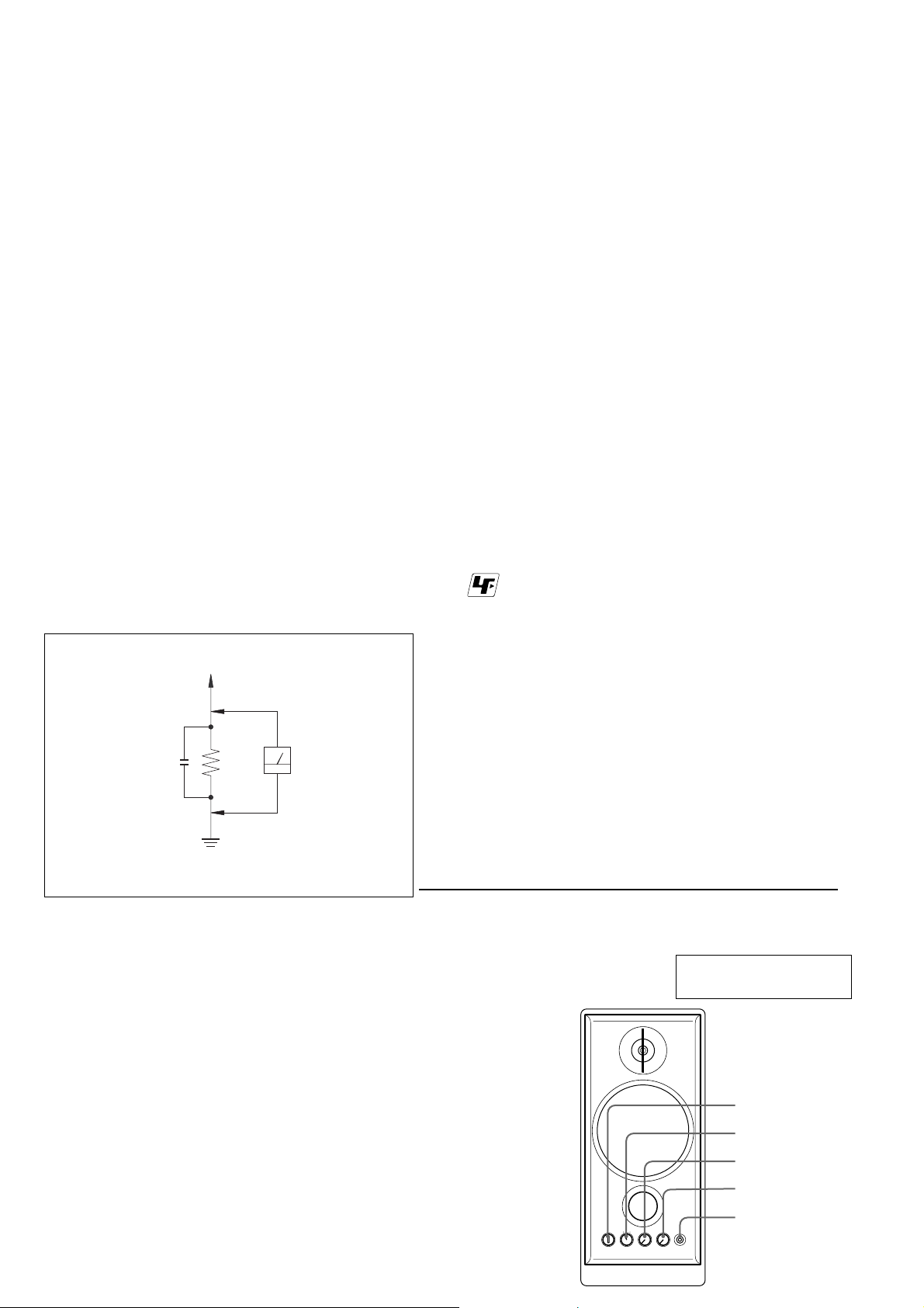
3. Measuring the voltage drop across a resistor by means of a
VOM or battery-operated AC voltmeter. The “limit” indication
is 0.75 V, so analog meters must have an accurate low-voltage
scale. The Simpson 250 and Sanwa SH-63Trd are examples of
a passive VOM that is suitable. Nearly all battery operated
digital multimeters that have a 2V AC range are suitable. (See
Fig. A)
To Exposed Metal
Par ts on Set
AC
0.15 µF
Fig. A. Using an AC voltmeter to check AC leakage.
1.5 kΩ
Earth Ground
Voltmeter
(0.75 V)
TABLE OF CONTENTS
Specifications ............................................................................ 1
1. GENERAL ................................................................... 2
2. DIAGRAMS
2-1. Schematic Diagram – Amp Board – ................................ 3
2-2. Printed Wiring Boards – Amp Board (Side A) – ............. 4
2-3. Printed Wiring Boards – Main Board (Side B) – ............ 5
2-4. Printed Wiring Boards – Control Board (Side A) –......... 6
2-5. Printed Wiring Boards – Control Board (Side B) –......... 7
2-6. Schematic Diagram – Control Board – ........................... 8
3. EXPLODED VIEWS
3-1. L-CH Section ................................................................... 10
3-2. R-CH Section .................................................................. 11
4. ELECTRICAL PARTS LIST .................................. 12
r
UNLEADED SOLDER
Boards requiring use of unleaded solder are printed with the lead-
free mark (LF) indicating the solder contains no lead.
(Caution: Some printed circuit boards may not come printed with
the lead free mark due to their particular size.)
: LEAD FREE MARK
Unleaded solder has the following characteristics.
• Unleaded solder melts at a temperature about 40°C higher than
ordinary solder.
Ordinary soldering irons can be used but the iron tip has to be
applied to the solder joint for a slightly longer time.
Soldering irons using a temperature regulator should be set to
about 350°C.
Caution: The printed pattern (copper foil) may peel away if
the heated tip is applied for too long, so be careful!
• Strong viscosity
Unleaded solder is more viscous (sticky, less prone to flow)
than ordinary solder so use caution not to let solder bridges
occur such as on IC pins, etc.
• Usable with ordinary solder
It is best to use only unleaded solder but unleaded solder may
also be added to ordinary solder.
Notes on chip component replacement
• Never reuse a disconnected chip component.
• Notice that the minus side of a tantalum capacitor may be
damaged by heat.
Flexible Circuit Board Repairing
• Keep the temperature of soldering iron around 270˚C
during repairing.
• Do not touch the soldering iron on the same conductor of the
circuit board (within 3 times).
• Be careful not to apply force on the conductor when soldering
or unsoldering.
SAFETY-RELATED COMPONENT WARNING!!
COMPONENTS IDENTIFIED BY MARK 0 OR DOTTED LINE WITH
MARK 0 ON THE SCHEMATIC DIAGRAMS AND IN THE PARTS
LIST ARE CRITICAL TO SAFE OPERATION. REPLACE THESE
COMPONENTS WITH SONY PARTS WHOSE PART NUMBERS
APPEAR AS SHOWN IN THIS MANUAL OR IN SUPPLEMENTS
PUBLISHED BY SONY.
2
LEFT SPEAKER
(FRONT)
SECTION 1
GENERAL
MOVIE MUSIC
MIN MAX
POWER SOUND MODE BASS VOLUME PHONES
MIN MAX
This section is extracted
from instruction manual.
POWER
SOUND MODE
BASS
VOLUME
PHONES
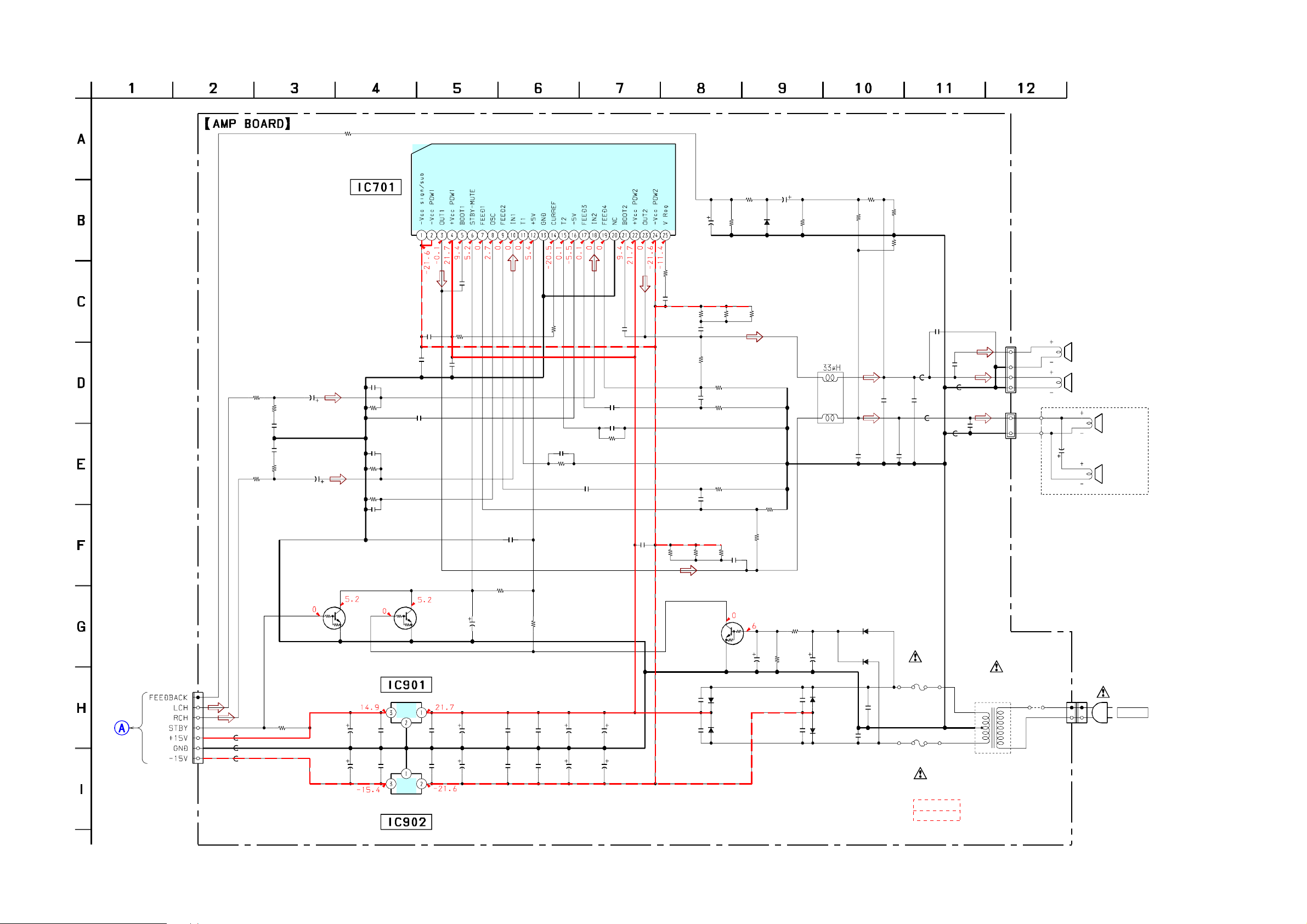
2-1. SCHEMATIC DIAGRAM – AMP BOARD –
R511
1k
R512
2.2k
C513
0.1
C611
0.1
R612
R611
2.2k
1k
DTC144EUA
MUTE SWITCH
CN701
7P
R712
22k
CONTROL
BOARD
(1/2)
(Page8)
FB903
FB902
FB901
C501
0.33
50V
Q702
SECTION 2
DIAGRAMS
R713
100
C502
1000p
C602
1000p
C601
0.33
50V
R705
10k
C909
47
25V
C910
47
25V
IC701
TDA7490
POWER AMP
C907
0.01
C908
0.01
C711
0.1
C718
1000p
C708
R510
0.1
10k
R610
10k
C710
24p
Q703
DTC144EUA
MUTE SWITCH
IC901
TA78M15S
+15V REG
C905
0.1
C906
0.1
R706
100k
C719
1000p
C603
0.033
C903
100
35V
C904
100
35V
C707
1
50V
R704
33k
C709
0.1
C717
1000p
C716
1000p
R703
4.7k
C703
C704
0.1
0.1
C605
330p
R601
22k
33k
R707
C701
C702
C604
470p
470
35V
470
35V
C503
C504
470p
C505
330p
R501
22k
C901
6800
C902
6800
C712
0.1
35V
35V
0.033
R605
33
R708
6.8
C713
0.1
C715
47
25V
R505
33
C507
470p
R502
47k
C506
470p
C606
470p
R606
33
Q701
DTC144EUA
AC DETECT
C914
0.1
C912
0.1
R504
4.7k
R503
68k
R603
68k
R607
R506
33
33
C607
470p
D904
1N5402
D901
1N5402
R710
10k
R711
10k
1SS355TE-17
R507
33
C706
0.1
50V
D703
R604
4.7k
R602
47k
C714
10
50V
R709
R702
47k
C913
0.1
C911
0.1
1k
R701
47k
L701
C705
0.1
50V
D903
1N5402
D902
1N5402
R609
3.3k
C608
0.22
1SS355TE-17
1SS355TE-17
C916
0.68
100V
R509
3.3k
C508
0.22
D701
D702
R608
4.7k
C915
0.68
100V
C510
1000p
C609
1000p
FH904
FH902
R508
4.7k
F901
*
F902
*
C511
1000p
FB501
FB601
FH903
FH901
FB503
FB603
C509
3.3
50V
C610
1000p
TRANSFORMER
T901
POWER
SRS-ZP1000
CN101
4P
1
4
CN201
2P
2
1
JW901
0
CN901
2P
TWEETER
SPEAKER
C1
3.3
50V
SP902
(L-CH)
SP901
(L-CH)
SP904
SPEAKER
(R-CH)
SP903
TWEETER
(R-CH)
AC IN
SRS-ZP1000
IC902
TA79015S
-15V REG
* F901, 902
T2.5AL/125V
T2.5AL/250V
US
AEP, UK
33
SRS-ZP1000
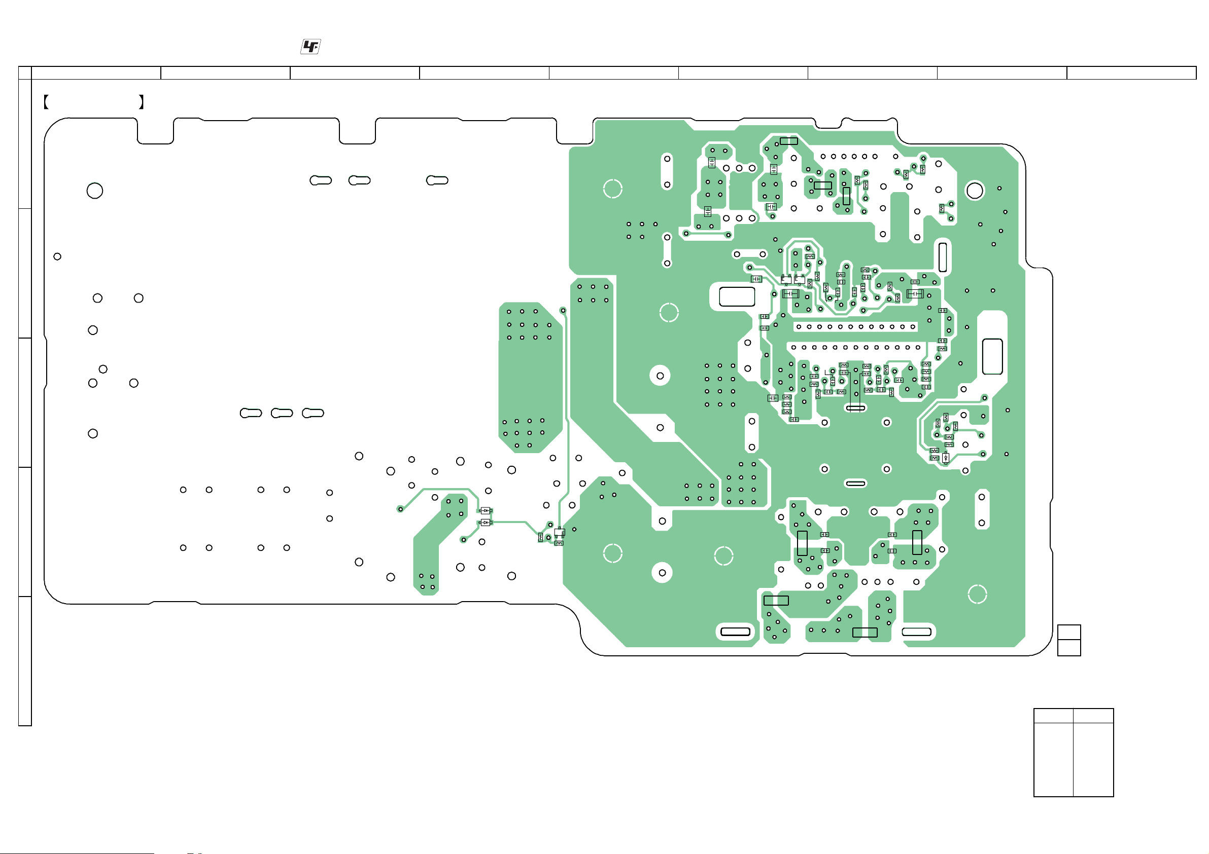
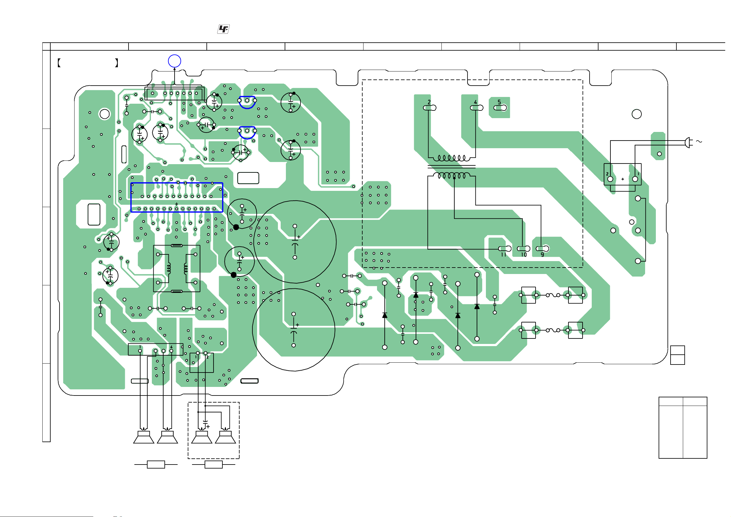
2-2. PRINTED WIRING BOARD – AMP BOARD (SIDE A) –
1
AMP BOARD
(SIDE A)
2
A
B
C
: Uses unleaded solder.
3 4 5 6 7
C906
C905
C703
C717
C716
C907
C704
C908
R607
FB901
Q703
C603
R602
C607
C712
R605
R606
FB902
R712
Q702
R704
R703
R705
C604
C606
R604
FB903
R610
C710
R601
R603
R611
R510
C709
C602
R501
C605
C502
C708
R503
C505
R612
C504
C506
C719
R706
C711
R707
R502
C503
R504
R511
R710
R512
C718
R507
R506
R505
C507
R608
R711
R713
C713
R708
R508
R609
R709
R509
8
9
D703
D702
R701
Q701
R702
FB603
FB601
C609
C610
C510
C511
FB501
D
D701
12
FB503
E
1-863-744-
(12)
• Semiconductor
Location
Ref. No. Location
D701 D-4
D702 D-4
D703 C-8
Q701 D-5
Q702 B-6
Q703 B-6
SRS-ZP1000
44
SRS-ZP1000
3-3. PRINTED WIRING BOARD – AMP BOARD (SIDE B) –
TP501
TP701
2
CONTROL BOARD
A
TP601
TP903
(Page 7)
TP902
1
AMP BOARD
(SIDE B)
A
C513
C501
1
C611
TP502
CN701
C601
TP602
7
TP702
TP712
B
TP707
IC701
TP704
TP706
TP711
TP708
24
C909
TP901
C910
2
: Uses unleaded solder.
3 4 5 6 7
T901
POWER TRANSFORMER
13
IC902
C904
IC901
TP703
C707
C701
13
TP904
C903
TP914
C901
TP913
CN901
8
9
AC IN
25
TP503
TP603
C715
C
L701
TP505
C714
TP506
C509
C508
TP604
13
TP709
64
C608
D
TP507
TP508
CN101
TP710
CN201
TP605
TP606
TP607
1
TP911
TP909
JW901
C702
TP905
TP906
C915
C706
C705
TP705
D903
C914
D902
C911
C912
TP908
TP907
D904
D901
TP912
FH902
F902
C916
FH904
F901
TP910
FH901
FH903
C913
12
1-863-744-
C902
(12)
• Semiconductor
Location
E
C1
Ref. No. Location
D901 D-6
D902 D-5
D903 D-5
D904 D-6
SRS-ZP1000
SP902
TWEETER
SPEAKER
L CH
SP901
SP903
TWEETER
R CH
SP904
SPEAKER
IC701 B-2
IC901 B-3
IC902 A-3
55
 Loading...