

Sony SRSZ-050-V Service manual
SRS-Z050V
SECTION 1
GENERAL
This section is extracted
from instruction manual.
SERVICE MANUAL
Ver 1.0 1999. 05
This product is marked in combination
with the VAIO Digital Studio Computer.
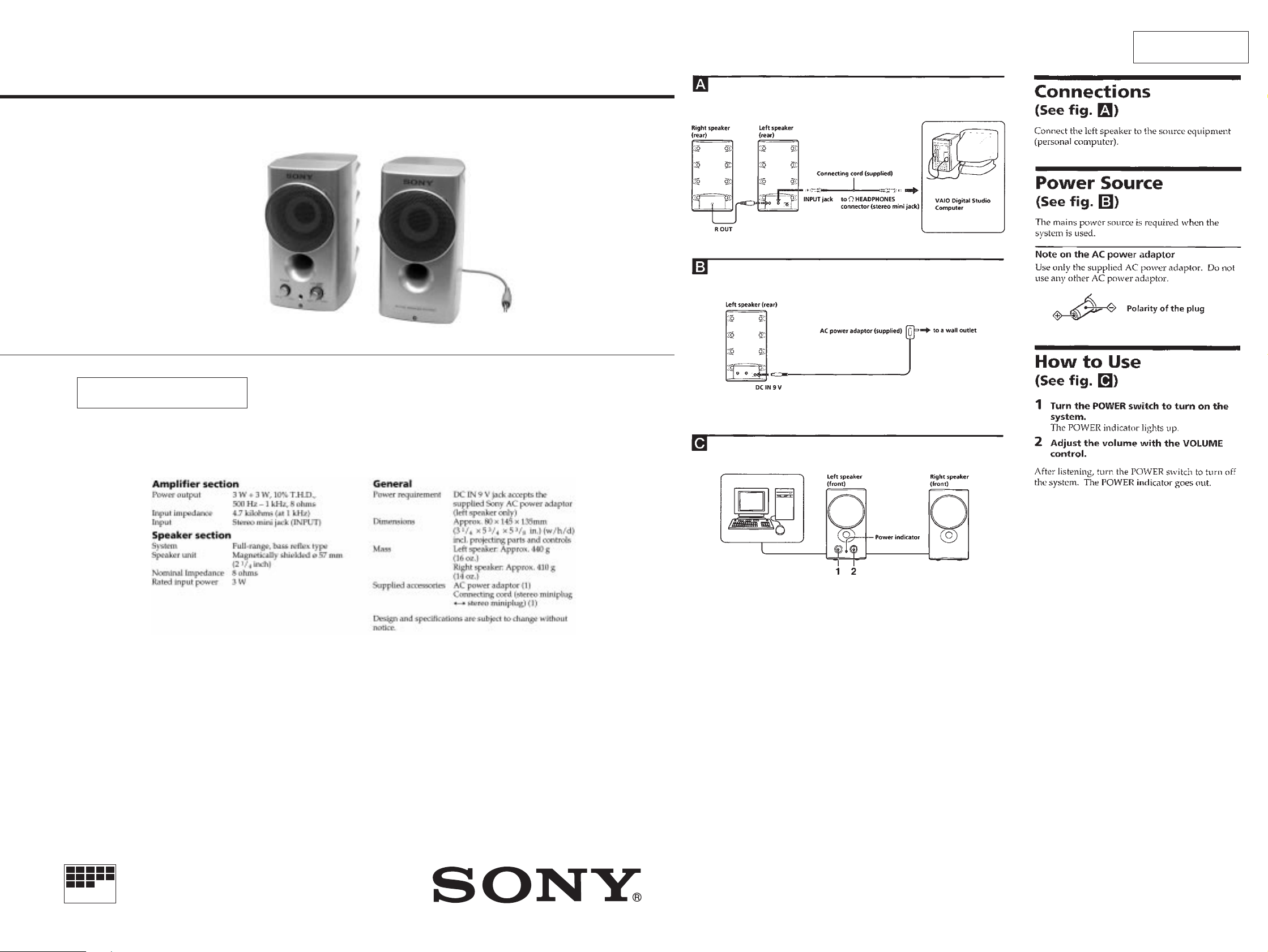
SPECIFICATIONS
US Model
MICROFILM
SAFETY-RELATED COMPONENT WARNING!!
STEREO ACTIVE SPEAKER SYSTEM
COMPONENTS IDENTIFIED BY MARK ! OR DOTTED LINE WITH
MARK ! ON THE SCHEMATIC DIAGRAMS AND IN THE PARTS
LIST ARE CRITICAL TO SAFE OPERATION. REPLACE THESE
COMPONENTS WITH SONY PARTS WHOSE PART NUMBERS
APPEAR AS SHOWN IN THIS MANUAL OR IN SUPPLEMENTS
PUBLISHED BY SONY .
— 2 —
SRS-Z050V
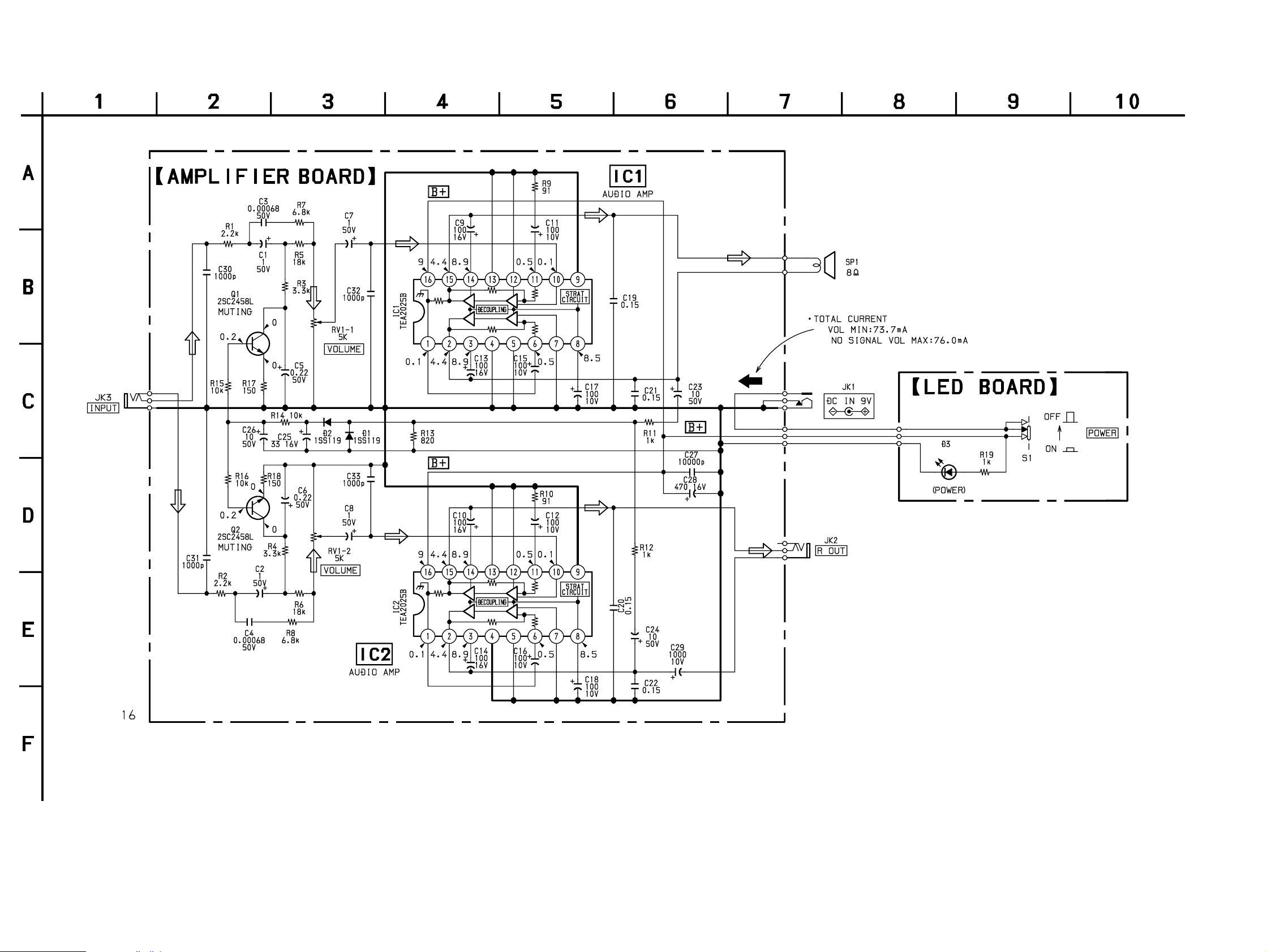
2-1. SCHEMATIC DIAGRAM
SECTION 2
DIAGRAMS
204GD
Note on Schematic Diagram:
• All capacitors are in µF unless otherwise noted. pF: µµF
50 WV or less are not indicated except for electrolytics
and tantalums.
• All resistors are in Ω and 1/
specified.
• % : indicates tolerance.
• C : panel designation.
• U : B+ Line.
4
W or less unless otherwise
• Power voltage is dc 9 V and fed with regulated dc power supply
from external power voltage jack.
• Voltages and waveforms are dc with respect to ground under nosignal (detuned) conditions.
• Voltages are taken with a VOM (Input impedance 10 MΩ).
Voltage variations may be noted due to normal production tolerances.
• Signal path.
F : AUDIO
— 3 — — 4 —
 Loading...