

Page 1

SRF-PSY04
SERVICE MANUAL
Ver 1.0 1999. 06
Photo: Blue model
SPECIFICATIONS
US Model
MICROFILM
FM STEREO/AM PLL
SYNTHESIZED RADIO
Page 2

TABLE OF CONTENTS
3
1. GENERAL ................................................................... 3
2. DISASSEMBLY ......................................................... 4
3. ELECTRICAL ADJUSTMENTS......................... 5
4. DIAGRAMS
4-1. Block Diagram ................................................................ 7
4-2. Printed Wiring Boards..................................................... 9
4-3. Schematic Diagram ......................................................... 11
4-4. IC Pin Function Description ........................................... 15
5. EXPLODED VIEW................................................... 16
6. ELECTRICAL PARTS LIST ............................... 17
HOW TO CHANGED THE CERAMIC FILTERS
This model is used two ceramic filters of CF1 and CF3.
Y ou must use same type of color marked cer amic filters in order to
meet same specifications.
Therefore, the ceramic filter must be changed two pieces together
since it’s supply two pieces in one package as a spare parts.
Mark Center frequency
CF
mark
CF1
Notes on chip component replacement
• Never reuse a disconnected chip component.
• Notice that the minus side of a tantalum capacitor may be damaged by heat.
red 10.70 MHz
blue 10.67 MHz
orange 10.73 MHz
black 10.64 MHz
white 10.76 MHz
– 2 –
Page 3

SECTION 1
GENERAL
This section is extracted from
instruction manual.
– 3 –
Page 4

SECTION 2
DISASSEMBLY
Note: Follow the disassembly procedure in the numerical order given.
FRONT CABINET
3
two claws
4
front cabinet
3
two claws
2
MAIN BOARD, KEY BOARD
two screws
(P2
×
8)
2
KEY board
2
MAIN board
1
lid, battery case
1
two claws
– 4 –
Page 5

SECTION 3
r
d
µ
)
ELECTRICAL ADJUSTMENTS
0 dB=1 µV
[AM]
Setting:
BAND switch: AM
AM RF signal
generator
30% amplitude
modulation by
400 Hz signal
Output level: as low as possible
[FM]
Setting:
BAND switch: FM
FM SENS switch: DX
FM RF signal
generator
22.5 kHz frequency
deviation by 400 Hz
signal
Output level: as low as possible
• Repeat the procedures in each adjustment several times, and the
tracking adjustments should be finally done by the trimmer capacitors.
MAIN board
TP (VT)
Put the lead-wire
antenna close to
the set.
MAIN board
TP (ANT)
0.01 µF
digital voltmete
+
–
set
set
level meter
16
Ω
+
–
(headphones) jack (J1)
2
level meter
16
Ω
+
–
2
(headphones) jack (J1)
AM IF ADJUSTMENT
Adjust for a maximum reading on level meter
T1 450 kHz
AM FREQUENCY COVERAGE ADJUSTMENT
Adjustment Part Frequency Display Reading on Digital Voltmeter
L5 530 kHz 2.7 ± 0.1V
Confirmation 1,710 kHz 8.9 ± 1V
AM TRACKING ADJUSTMENT
Adjust for a maximum reading on level meter
L2 580 kHz
CT1 1,490 kHz
FM VCO VOLT A GE CONFIRMATION
Frequency Display Reading on Digital Voltmeter
87.5 MHz 2.7 ± 0.1V
108 MHz 8.9 ± 1V
FM TRACKING ADJUSTMENT
Adjust for a maximum reading on level meter
L3 87.5 MHz
CT2 108 MHz
FM STEREO (76 kHz) Adjustment
Setting:
BAND switch: FM
FM SENS switch: DX
FM RF signal
generator
0.01 µF
MAIN boar
TP (ANT)
set
Adjustment Location: Main Board (See page 6)
Carrier frequency : 98 MHz
Modulation : 1 kHz, 22.5 kHz deviation
Output level : 562
V (55 dB
Procedure:
1. Connect the frequency counter to TP (76 kHz) as shown the
figure below.
2. Tune the set to 98 MHz.
3. Adjust RV1 for 76 kHz reading on the frequency counter.
Specification: 75.5 to 76.5 kHz
frequency
counter
MAIN board
TP (76 kHz)
1 µF
+
+
–
Adjustment Location: MAIN board (See page 6)
– 5 –
Page 6
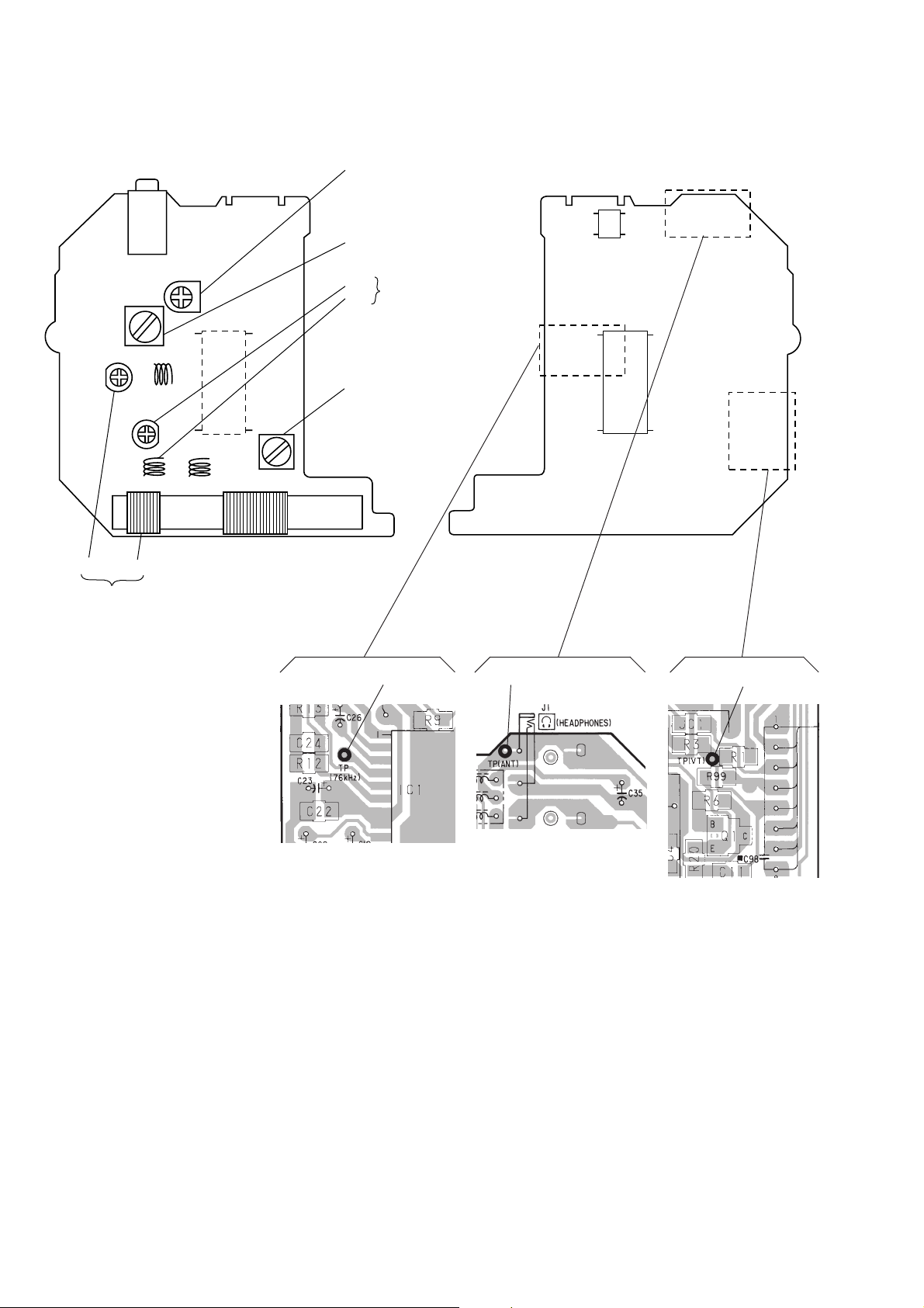
Adjustment Location:
– MAIN BOARD (Component Side) –
J1
IC1
L4
L1
CT1
L2
AM T rac king Adjustment
RV1
FM Stereo (76 kHz)
Adjustment
L5
AM Frequency Coverage
Adjustment
CT2
FM T rac king
L3
Adjustment
T1
AM IF Adjustment
– MAIN BOARD (Conductor Side) –
IC2
IC1
TP (76 kHz) TP (ANT) TP (VT)
– 6 –
Page 7

4-1. BLOCK DIAGRAM
SRF-PSY04
SECTION 4
DIAGRAMS
FM SENS
LOCAL
L2
AM FERRITE-ROD
ANTENNA
CT1, L2
AM TRACKING
CF1
10.7MHz
BAND
SELECT
15
Q2
26
FM DISCRI
FM IF AMP/
DISCRI
TUNING
INDICATOR
AM IF AMP/
DET
FM/AM FRONT-END,
FM/AM DET, MPX
S1
B.P.F.
DX
CT1
FM RF
CT2, L3
FM TRACKING
D1-1
L3
L5
AM FREQUENCY
COVERAGE
CT2
LOW-PASS
FILTER
Q101, 102
D2
L5
AM OSC
IC1
FM OSC
MIX OUT
FM VCO
BUFFER
Q1
FM/AM
16
L4
FM OSC
AM IF
FM RF
IN
18
FM
RF
20
AM RF
IN
19
FM
FRONT-END
AM
FRONT-END
AM OSC
24 22
D1-2 D3
CF3
10.7MHz
T1
CF2
450kHz
FM
IF IN
13
AM
IF IN
14
FM/AM BAND
SELECT SWITCH
VREF
REG
TUNE IND9AFC1/AGC
12
+
REGULATOR
PD1
PD2
PILOT DET
LPF2
PILOT DET
LPF1
+
721
VCC
1/2
COUNTER
1/2
COUNTER
PLL
LPF1
123
B+
DECODER
AMP
SWITCH
L.P.F.
VCO
PLL
LPF2
29
FM STEREO
L-CH
OUT
R-CH
OUT
ST IND
VCO
27
RV1
(76kHz)
HEADPHONE AMP
IN2
IN1
IC2
POWER
AMP
POWER
AMP
MUTE
CONTROL
MT/SW
10
OUT2
OUT1
7
J1
9
2
(HEADPHONE)
RV2
VOL
6
5
4
–1
–2
4
2
• SIGNAL PATH
05
: FM
: AM
EO
PC0 – PC3 PB0 – PB2
KEY MATRIX
S101 – 111
VCOL
37, 38, 12 – 5
181916
VCOH
7
BAND
XIN
COM0 – COM3
32 – 29
LIQUID CRYSTAL DISPLAY
XOUT
12 13 9 11
X1
75kHz
LCD0 – LCD8
28 – 20
LCD101
SYSTEM CONTROLLER,
LIQUID CRYSTAL DISPLAY DRIVER,
KEY CONTROL
IC101
POWER
SYSTEM CONTROLLER (IC101) B+
FM/AM TUNER (IC1),
HEADPHONE AMP (IC2) B+
PLL LOW-PASS FILTER CIRCUIT B+
D102
DC/DC
CONVERTER
Q106, 107, T101
10
MUTE
B+ SWITCH
Q103, 104
VOLTAGE
DETECT
IC102
CE
6
BEEP
DRY BATTERY
SIZE “AAA”
(IEC DESIGNATION R03)
2PCS. 3V
– 7 –
– 8 –
Page 8

Page 9
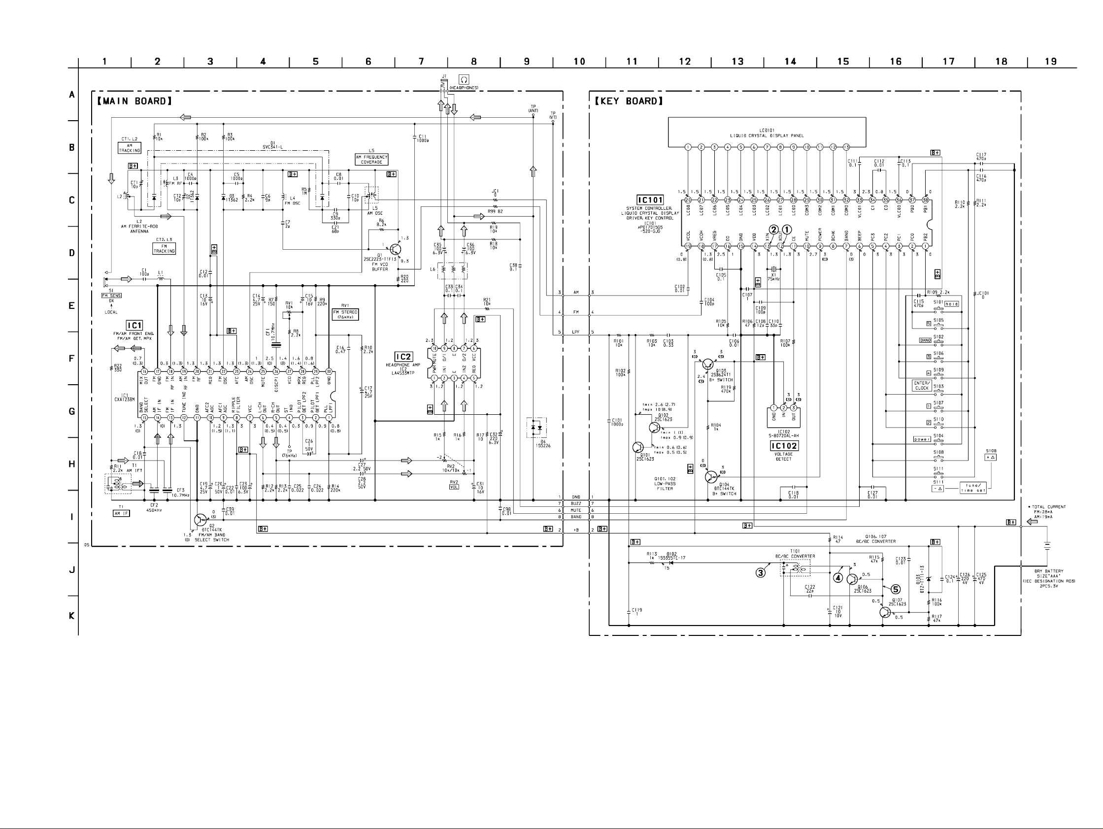
4-3. SCHEMATIC DIAGRAM • See page 13 for Waveforms. • See page 14 for IC Block Diagrams.
SRF-PSY04
– 11 –
Note on Schematic Diagram:
• All capacitors are in µF unless otherwise noted. pF: µµF
50 WV or less are not indicated except for electrolytics
and tantalums.
• All resistors are in Ω and 1/
specified.
¢
•
• C : panel designation.
• U : B+ Line.
• H : adjustment for repair .
• P ower voltage is dc 3 V and fed with regulated dc power
• Voltages and waveforms are dc with respect to ground
: internal component.
supply from battery terminal.
under no-signal (detuned) conditions.
4
W or less unless otherwise
no mark : FM
( ) : AM
〈〈 〉〉 : POWER OFF
• Voltages are taken with a VOM (Input impedance 10 MΩ).
Voltage variations may be noted due to normal production tolerances.
• Waveforms are taken with a oscilloscope.
Voltage variations may be noted due to normal production tolerances.
• Circled numbers refer to waveforms.
• Signal path.
F : FM
f : AM
– 12 –
Page 10

• Waveforms
– KEY Board –
1 IC101 !™ XOUT
500 mV/DIV, 10 µs/DIV
• IC Block Diagrams
– MAIN Board –
IC1 CXA1238M-T6
GND
PLL LPF2
MPX REG
28
2930 242526 212223 181920 1617
27
VCO
MUTE
FM DISCRI
AM OSC
AFC
REG
FM OSC
FM RF
FM RF IN
AM RF IN
FM GND
FM/AM FE OUT
13.3 µs
2 IC101 !£ XIN
500 mV/DIV, 10 µs/DIV
13.3 µs
3 T101
10 V/DIV, 200 ns/DIV
1.2 Vp-p
2 Vp-p
34 Vp-p
FM FRONT-END
AM FRONT-END
REGULATOR
MPX
VCO
MONO/STEREO
SELECT
1
2 3 4 5 6 7 8 9
PLL LPF1
PILOT DET LPF2
PILOT DET LPF2
ST IND/VCO CHECK
REGULATOR
1/2
COUNTER
1/2
COUNTER
MUTING
DECORD
AMP
R-CH OUT
PD1
L-CH OUT
PD2
AUTO
BLEND
RIPPLE
FILTER
VCC
AGC AFC1
RIPPLE FILTER
BAND-PASS
MUTE
10
AGC AFC2
FM IF/
DISCRI
AM IF/
DET
TUNING
INDICATOR
11
12
GND
TUNE IND
13
FM IF IN
14
AM IF IN
15
BAND SELECT
424 ns
4 Q106 Collector
2 V/DIV, 200 ns/DIV
320 ns
5 Q106 Base, Q107 Collector
200 mV/DIV, 200 ns/DIV
5.2 Vp-p
616 mVp-p
IC2 LA4533M
POWER
1
P/SW
IN1
PRE GND
IN2
REF
SWITCH
2
3
4
BIAS
5
POWER
AMP
POWER
AMP
MUTE
CONTROL
MT/SW
10
OUT1
9
8
POWER GND
OUT2
7
6
VCC
320 ns
– 13 –
– 14 –
Page 11

4-4. IC PIN FUNCTION DESCRIPTION
•
KEY BOARD IC101 µPD17015GS-520-GJG
(SYSTEM CONTROLLER, LIQUID CRYSTAL DISPLAY DRIVER, KEY CONTROL)
Pin No. Pin Name I/O Description
1 PB2 I
2 to 5 PC0 to PC3 O
6 BEEP O
7 BAND O
8 BCHK —
9 POWER O
10 MUTE O
11 CE I
12 XOUT O
13 XIN I
14 VDD —
15 GND —
16 EO O
17 VREG —
18 VCOH I
19 VCOL I
20 to 28 LCD8 to LCD0 O
29 to 32 COM3 to COM0 O
33 VLCD1 —
34 C1 —
35 C0 —
36 VLCD0 —
37, 38 PB0, PB1 I
Key return signal input for the key matrix
Key scan signal output for the key matrix
Beep sound drive signal output terminal
FM/AM band selection signal output terminal “L”: FM, “H”: AM
Not used (open)
Power on/off control signal output for the radio system power supply “H”: power on
Muting on/off control signal output to the headphone amplifier (IC2) “L”: muting on
Power failure detection signal input from the voltage detect (IC102) Normally: “H”
System clock output terminal (75 kHz)
System clock input terminal (75 kHz)
Power supply terminal (+3V)
Ground terminal
PLL error signal output terminal
Power supply terminal (connected to the coupling capacitor)
FM VCO input terminal
AM VCO input terminal
Segment drive signal output to the liquid crystal display (LCD101)
Common drive signal output to the liquid crystal display (LCD101)
Terminal for doubler circuit capacitor connection to develop liquid crystal display drive voltage
Key return signal input for the key matrix
– 15 –
Page 12
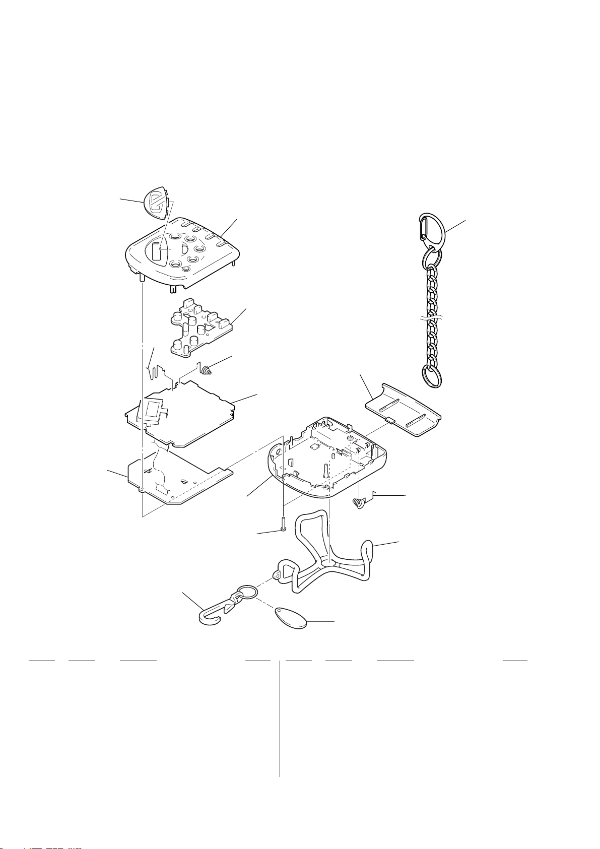
SECTION 5
EXPLODED VIEW
NOTE:
• -XX and -X mean standardized parts, so they
may have some difference from the original
one.
• Color Indication of Appearance Parts
Example:
KNOB, BALANCE (WHITE) . . . (RED)
↑↑
Parts Color Cabinet's Color
4
3
• Items marked “*” are not stocked since they
are seldom required for routine service. Some
delay should be anticipated when ordering
these items.
• The mechanical parts with no reference number in the exploded views are not supplied.
• Accessories and packing materials are given
in the last of the electrical parts list.
5
6
7
9
14
8
2
1
11
13
Ref. No. Part No. Description Remark
1 3-925-196-21 CABINET (REAR) (BLUE)
1 3-925-196-31 CABINET (REAR) (VIOLET)
2 A-3679-692-A MAIN BOARD, COMPLETE
3 3-925-201-01 SPRING (+), BATTERY
4 3-925-198-11 PLATE, TRANSPARENT (for BLUE)
10
12
not supplied
Ref. No. Part No. Description Remark
7 3-925-192-01 SPRING (–), BATTERY
8 A-3679-693-A KEY BOARD, COMPLETE
9 3-925-197-11 LID, BATTERY CASE (BLUE)
9 3-925-197-21 LID, BATTERY CASE (VIOLET)
10 3-925-193-01 SPRING (+/–), BATTERY
4 3-925-198-21 PLATE, TRANSPARENT (for VIOLET)
5 3-925-195-11 CABINET (FRONT) (BLUE)
5 3-925-195-21 CABINET (FRONT) (VIOLET)
6 1-762-412-21 SWITCH, RUBBER KEY (BLUE)...(VIOLET)
6 1-762-412-31 SWITCH, RUBBER KEY (VIOLET)...(BLUE)
11 7-685-105-14 TAPPING +P 2X8 NON-SLIT
12 3-037-724-01 GUARD (YELLOW)... (BLUE)
12 3-037-724-11 GUARD (BLUE)... (VIOLET)
13 3-028-093-01 CLIP
14 3-036-709-01 CHAIN
– 16 –
Page 13

SECTION 6
ELECTRICAL PARTS LIST
KEY MAIN
NOTE:
• Due to standardization, replacements in the
parts list may be different from the parts specified in the diagrams or the components used
on the set.
• -XX and -X mean standardized parts, so they
may have some difference from the original
one.
• RESISTORS
All resistors are in ohms.
METAL: Metal-film resistor.
METAL OXIDE: Metal oxide-film resistor.
F: nonflammable
Ref. No. Part No. Description Remark Ref. No. Part No. Description Remark
* A-3679-693-A KEY BOARD, COMPLETE
********************
< CAPACITOR >
C101 1-163-009-11 CERAMIC CHIP 0.001uF 10% 50V
C102 1-163-031-11 CERAMIC CHIP 0.01uF 50V
C103 1-164-336-11 CERAMIC CHIP 0.33uF 25V
C104 1-163-251-11 CERAMIC CHIP 100PF 5% 50V
C105 1-163-038-00 CERAMIC CHIP 0.1uF 25V
C106 1-163-031-11 CERAMIC CHIP 0.01uF 50V
C107 1-164-346-11 CERAMIC CHIP 1uF 16V
C108 1-163-229-11 CERAMIC CHIP 12PF 5% 50V
C109 1-163-251-11 CERAMIC CHIP 100PF 5% 50V
C110 1-163-239-11 CERAMIC CHIP 33PF 5% 50V
C111 1-163-038-00 CERAMIC CHIP 0.1uF 25V
C112 1-163-031-11 CERAMIC CHIP 0.01uF 50V
C113 1-163-038-00 CERAMIC CHIP 0.1uF 25V
C115 1-163-133-00 CERAMIC CHIP 470PF 5% 50V
C116 1-163-133-00 CERAMIC CHIP 470PF 5% 50V
C117 1-163-133-00 CERAMIC CHIP 470PF 5% 50V
C118 1-163-031-11 CERAMIC CHIP 0.01uF 50V
C119 1-164-346-11 CERAMIC CHIP 1uF 16V
C121 1-124-261-00 ELECT 10uF 20% 50V
C122 1-163-235-11 CERAMIC CHIP 22PF 5% 50V
C123 1-163-031-11 CERAMIC CHIP 0.01uF 50V
C124 1-163-038-00 CERAMIC CHIP 0.1uF 25V
C125 1-126-518-11 ELECT 470uF 20% 4V
C126 1-124-434-00 ELECT 220uF 20% 4V
C127 1-163-031-11 CERAMIC CHIP 0.01uF 50V
< DIODE >
D102 8-719-988-61 DIODE 1SS355TE-17
D103 8-719-977-40 DIODE DTZ-TT11-13
< IC >
IC101 8-759-343-08 IC uPD17015GS-520-GJG
IC102 8-759-542-36 IC S-80720AL-AH-T1
< SHORT >
JC101 1-216-295-00 SHORT 0
< LIQUID CRYSTAL DISPLAY >
LCD101 1-810-932-11 DISPLAY PANEL, LIQUID CRYSTAL
• Items marked “*” are not stocked since they
are seldom required for routine service.
Some delay should be anticipated when ordering these items.
• SEMICONDUCTORS
In each case, u: µ, for example:
uA. . : µA. . uPA. . : µPA. .
uPB. . : µPB. . uPC. . : µPC. .
uPD. . : µPD. .
• CAPACITORS
uF: µF
• COILS
uH: µH
< TRANSISTOR >
Q101 8-729-120-28 TRANSISTOR 2SC1623-L5L6
Q102 8-729-120-28 TRANSISTOR 2SC1623-L5L6
Q103 8-729-141-48 TRANSISTOR 2SB624-BV345
Q104 8-729-027-60 TRANSISTOR DTC144TKA-T146
Q106 8-729-120-28 TRANSISTOR 2SC1623-L5L6
Q107 8-729-120-28 TRANSISTOR 2SC1623-L5L6
< RESISTOR >
R101 1-216-073-00 METAL CHIP 10K 5% 1/10W
R102 1-216-097-00 RES, CHIP 100K 5% 1/10W
R103 1-216-073-00 METAL CHIP 10K 5% 1/10W
R104 1-216-049-11 RES, CHIP 1K 5% 1/10W
R105 1-216-073-00 METAL CHIP 10K 5% 1/10W
R106 1-216-017-00 RES, CHIP 47 5% 1/10W
R107 1-216-097-00 RES, CHIP 100K 5% 1/10W
R109 1-216-057-00 METAL CHIP 2.2K 5% 1/10W
R110 1-216-057-00 METAL CHIP 2.2K 5% 1/10W
R111 1-216-057-00 METAL CHIP 2.2K 5% 1/10W
R113 1-216-049-11 RES, CHIP 1K 5% 1/10W
R114 1-216-017-00 RES, CHIP 47 5% 1/10W
R115 1-216-089-00 RES, CHIP 47K 5% 1/10W
R116 1-216-097-00 RES, CHIP 100K 5% 1/10W
R117 1-216-089-00 RES, CHIP 47K 5% 1/10W
R119 1-216-113-00 METAL CHIP 470K 5% 1/10W
< TRANSFORMER >
T101 1-449-138-11 TRANSFORMER, DC-DC CONVERTER
< VIBRATOR >
X1 1-567-769-11 VIBRATOR, CRYSTAL (75kHz)
**************************************************************
* A-3679-692-A MAIN BOARD, COMPLETE
*********************
< CAPACITOR >
C1 1-163-251-11 CERAMIC CHIP 100PF 5% 50V
C4 1-163-141-00 CERAMIC CHIP 0.001uF 5% 50V
C5 1-163-141-00 CERAMIC CHIP 0.001uF 5% 50V
C6 1-163-092-00 CERAMIC CHIP 9PF 0.25PF 50V
C7 1-163-085-00 CERAMIC CHIP 2PF 50V
– 17 –
Page 14

MAIN
Ref. No. Part No. Description Remark
C8 1-163-031-11 CERAMIC CHIP 0.01uF 50V
C9 1-163-129-00 CERAMIC CHIP 330PF 5% 50V
C10 1-163-227-11 CERAMIC CHIP 10PF 0.5PF 50V
C11 1-163-009-11 CERAMIC CHIP 0.001uF 10% 50V
C12 1-101-004-00 CERAMIC 0.01uF 50V
C13 1-104-396-11 ELECT 10uF 20% 16V
C14 1-126-163-11 ELECT 4.7uF 20% 50V
C15 1-104-396-11 ELECT 10uF 20% 16V
C16 1-164-005-11 CERAMIC CHIP 0.47uF 25V
C17 1-126-163-11 ELECT 4.7uF 20% 50V
C18 1-163-031-11 CERAMIC CHIP 0.01uF 50V
C19 1-126-163-11 ELECT 4.7uF 20% 50V
C20 1-104-942-11 ELECT 1uF 20% 50V
C21 1-163-113-00 CERAMIC CHIP 68PF 5% 50V
C22 1-163-031-11 CERAMIC CHIP 0.01uF 50V
C23 1-126-382-11 ELECT 100uF 20% 6.3V
C24 1-163-033-00 CERAMIC CHIP 0.022uF 50V
C25 1-163-033-00 CERAMIC CHIP 0.022uF 50V
C26 1-104-942-11 ELECT 1uF 20% 50V
C27 1-124-257-00 ELECT 2.2uF 20% 50V
C28 1-124-257-00 ELECT 2.2uF 20% 50V
C31 1-104-396-11 ELECT 10uF 20% 16V
C32 1-124-635-00 ELECT 220uF 20% 6.3V
C33 1-164-004-11 CERAMIC CHIP 0.1uF 10% 25V
C34 1-164-004-11 CERAMIC CHIP 0.1uF 10% 25V
C35 1-126-382-11 ELECT 100uF 20% 6.3V
C36 1-126-382-11 ELECT 100uF 20% 6.3V
C38 1-163-038-00 CERAMIC CHIP 0.1uF 25V
C39 1-163-031-11 CERAMIC CHIP 0.01uF 50V
C98 1-101-004-00 CERAMIC 0.01uF 50V
< FILTER >
CF1 1-577-324-11 FILTER, CERAMIC (10.7MHz)
CF2 1-577-072-21 FILTER, CERAMIC (450kHz)
CF3 1-577-324-11 FILTER, CERAMIC (10.7MHz)
< TRIMMER >
CT1 1-141-304-21 CAP, TRIMMER 10PF
CT2 1-141-304-21 CAP, TRIMMER 10PF
Ref. No. Part No. Description Remark
< COIL >
L1 1-428-772-11 COIL, AIR-CORE
L2 1-501-781-11 ANTENNA, FERRITE-ROD (AM)
L3 1-411-529-11 COIL, AIR-CORE (FM RF)
L4 1-428-817-11 COIL, AIR-CORE (FM OSC)
L5 1-406-485-11 COIL (AM OSC)
L6 1-411-393-11 COIL, TRAP
< TRANSISTOR >
Q1 8-729-102-07 TRANSISTOR 2SC2223-F13
Q2 8-729-027-60 TRANSISTOR DTC144TKA-T146
< RESISTOR >
R1 1-216-073-00 METAL CHIP 10K 5% 1/10W
R2 1-216-097-00 RES, CHIP 100K 5% 1/10W
R3 1-216-097-00 RES, CHIP 100K 5% 1/10W
R4 1-216-057-00 METAL CHIP 2.2K 5% 1/10W
R5 1-216-121-00 RES, CHIP 1M 5% 1/10W
R6 1-216-071-00 METAL CHIP 8.2K 5% 1/10W
R7 1-216-029-00 METAL CHIP 150 5% 1/10W
R8 1-216-057-00 METAL CHIP 2.2K 5% 1/10W
R9 1-216-105-00 RES, CHIP 220K 5% 1/10W
R10 1-216-057-00 METAL CHIP 2.2K 5% 1/10W
R11 1-216-057-00 METAL CHIP 2.2K 5% 1/10W
R12 1-216-057-00 METAL CHIP 2.2K 5% 1/10W
R13 1-216-057-00 METAL CHIP 2.2K 5% 1/10W
R14 1-216-105-00 RES, CHIP 220K 5% 1/10W
R15 1-216-049-11 RES, CHIP 1K 5% 1/10W
R16 1-216-049-11 RES, CHIP 1K 5% 1/10W
R17 1-216-001-00 METAL CHIP 10 5% 1/10W
R18 1-216-073-00 METAL CHIP 10K 5% 1/10W
R19 1-216-073-00 METAL CHIP 10K 5% 1/10W
R20 1-216-033-00 METAL CHIP 220 5% 1/10W
R21 1-216-073-00 METAL CHIP 10K 5% 1/10W
R22 1-216-037-00 METAL CHIP 330 5% 1/10W
R99 1-216-023-00 METAL CHIP 82 5% 1/10W
< VARIABLE RESISTOR >
< DIODE >
D1 8-719-945-31 DIODE SVC341-L
D2 8-713-100-11 DIODE 1T362
D3 8-713-100-11 DIODE 1T362
D4 8-719-800-76 DIODE 1SS226
< IC >
IC1 8-752-062-48 IC CXA1238M-T6
IC2 8-759-802-75 IC LA4533M
< JACK >
J1 1-770-894-11 JACK (2 (HEADPHONES))
< SHORT >
JC1 1-216-295-00 SHORT 0
RV1 1-228-994-00 RES, ADJ, METAL 10K
RV2 1-223-939-11 RES, VAR, CARBON 10K/10K (VOL)
< SWITCH >
S1 1-572-552-11 SWITCH, SLIDE (FM SENS)
< TRANSFORMER >
T1 1-404-790-11 TRANSFORMER, IF (AM IFT)
**************************************************************
MISCELLANEOUS
***************
6 1-762-412-21 SWITCH, RUBBER KEY (BLUE)...(VIOLET)
6 1-762-412-31 SWITCH, RUBBER KEY (VIOLET)...(BLUE)
************************************************************
– 18 –
Page 15

Ref. No. Part No. Description Remark
ACCESSORIES & PACKING MATERIALS
********************************
3-028-093-01 CLIP
3-036-709-01 CHAIN
3-037-724-01 GUARD (YELLOW)... (BLUE)
3-037-724-11 GUARD (BLUE)... (VIOLET)
3-867-370-11 MANUAL, INSTRUCTION (ENGLISH) (US)
8-953-342-99 HEADPHONE, STEREO MDR-24
Ref. No. Part No. Description Remark
– 19 –
Page 16

SRF-PSY04
Sony Corporation
Personal Audio Company9-927-137-11
– 20 –
Printed in Japan © 1999. 6
99F0520-1
Published by General Engineering Dept.
 Loading...