

Sony SPP-888 Service Manual
SPP-888
SERVICE MANUAL
Base phone Cordless
SPECIFICATIONS
General
Dial signal
Tone, 10 PPS (pulse) selectable
Supplied accessories
See page 3.
Cordless handset
Power source
Rechargeable battery pack BP-T16
Battery life
Standby: Approx. 8 days
Talk: Approx. 6 hours
Battery charging time
Approx. 12 hours
Dimensions
Approx. 54 × 195 × 49 mm (w/h/d),
antenna excluded
(approx. 2 1/4 × 7 3/4 × 1 15/16 inches)
Antenna: Approx. 285 mm
(approx. 11 1/4 inches)
Mass
Approx. 255 g (approx. 8 oz), battery
included
E Model
handset
Base phone
Power source
DC 9V from AC power adaptor
Dimensions
Approx. 185 × 95 × 215 mm (w/h/d),
antenna excluded
(approx. 7 3/8 × 3 3/4 × 8 1/2 inches)
Antenna: Approx. 700 mm
(approx. 27 5/8 inches)
Mass
Approx. 755 g (approx. 27 oz)
Cordless handset charge cradle
Power source
DC 9V from AC power adaptor
Dimensions
Approx. 68 × 90 × 220 mm (w/h/d)
(approx. 2 3/4 × 3 5/8 × 8 3/4 inches)
Mass
Approx. 180 g (approx. 6 oz), wall bracket
included
Design and specifications are subject to
change without notice.
MICROFILM
CORDLESS TELEPHONE
1

TABLE OF CONTENTS
1. GENERAL
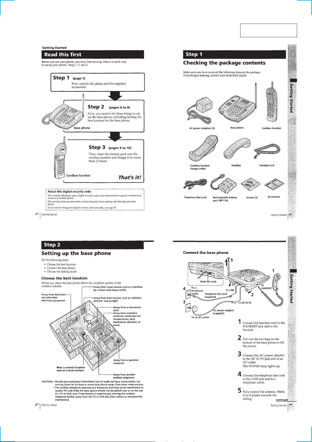
Read this first........................................................................... 3
Checking the package contents ...............................................3
Setting up the base phone ........................................................ 3
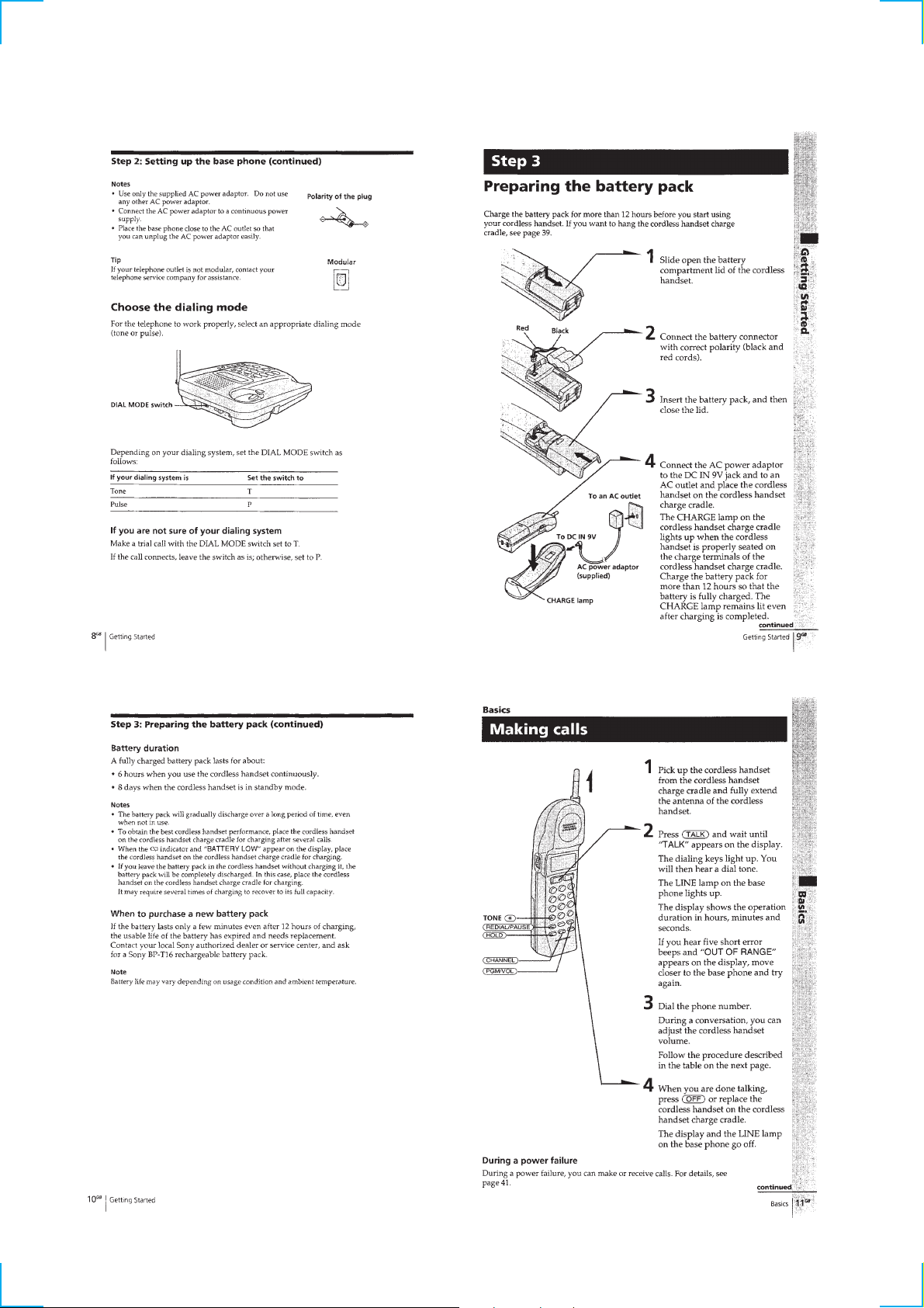
Preparing the battery pack ....................................................... 4
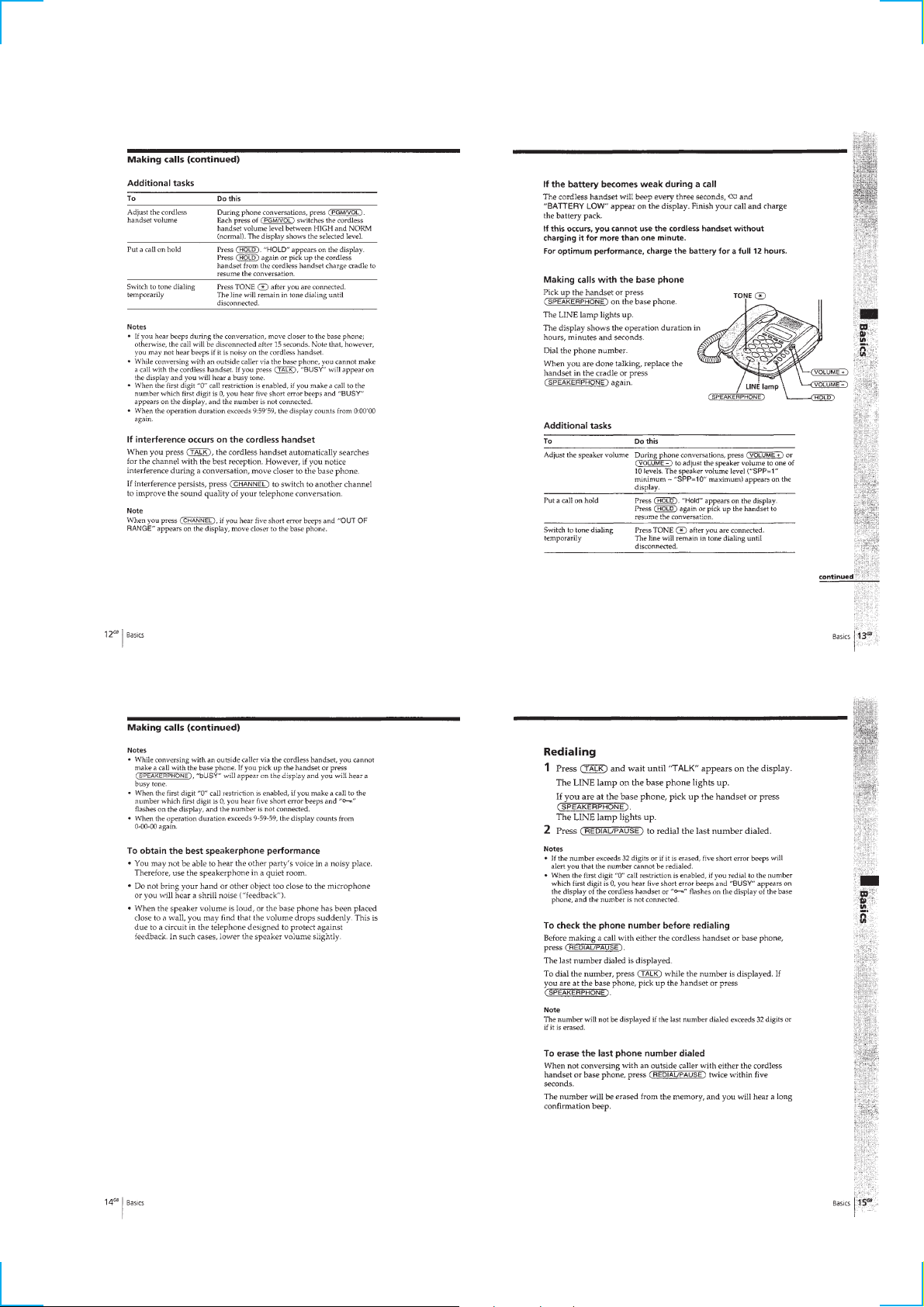
Making calls ............................................................................ 4
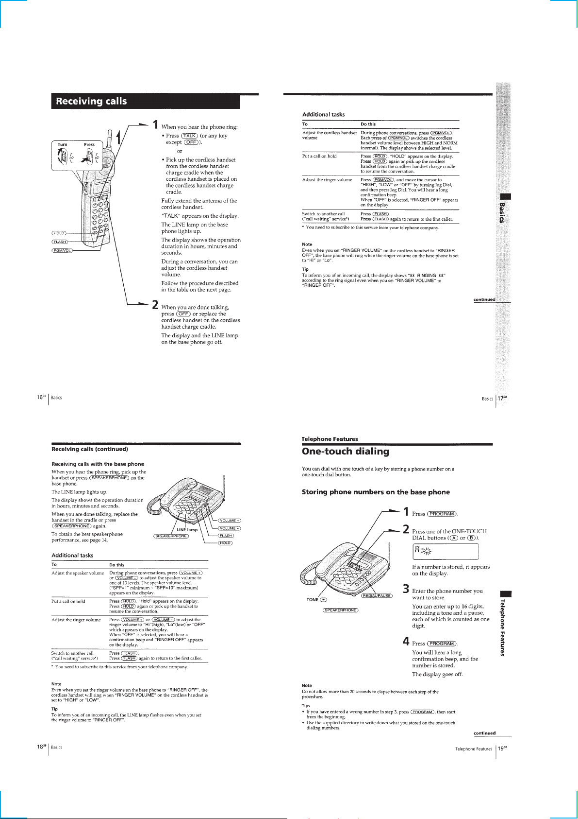
Receiving calls......................................................................... 6
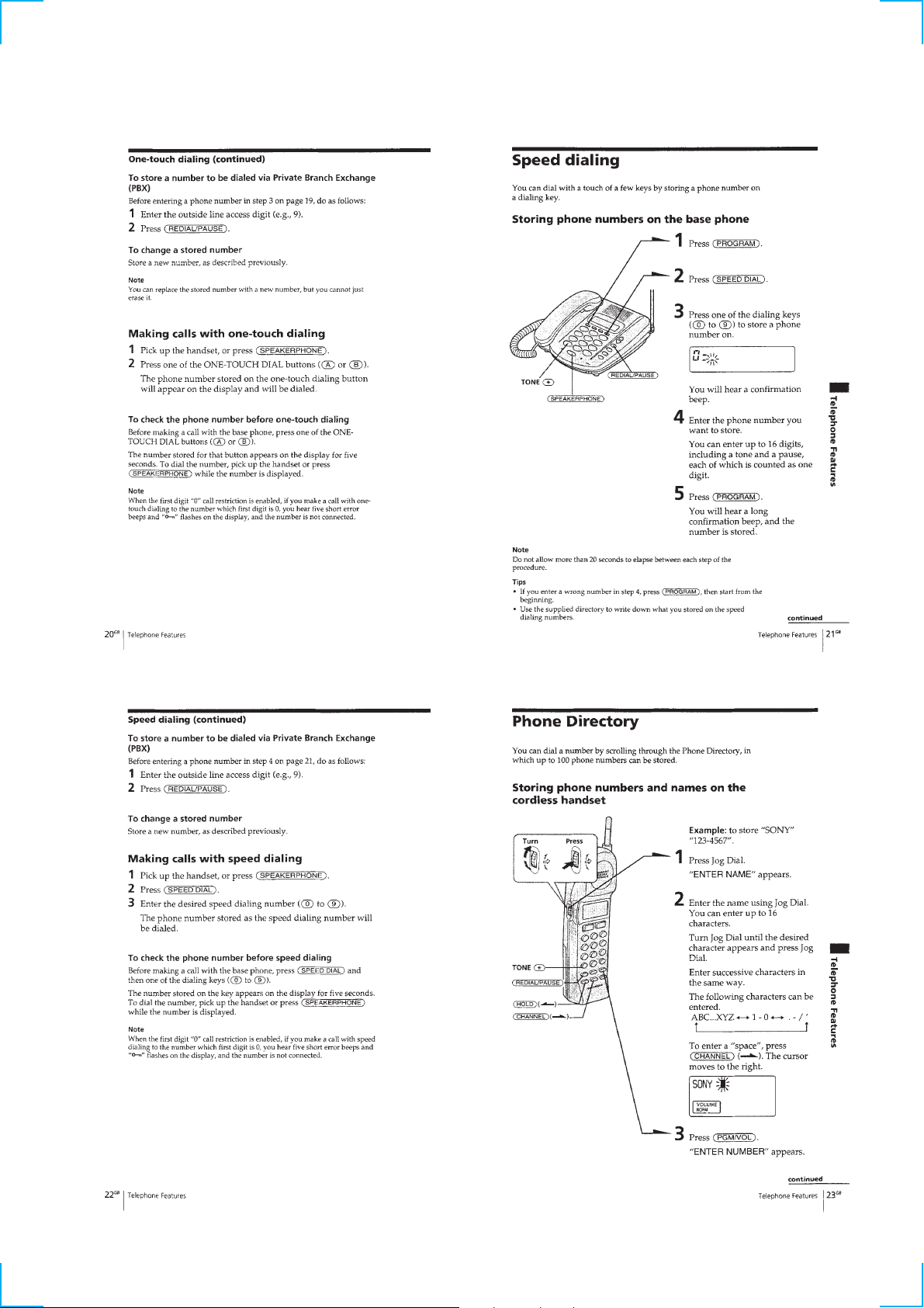
One-touch dialing .................................................................... 6
Speed dialing ........................................................................... 7
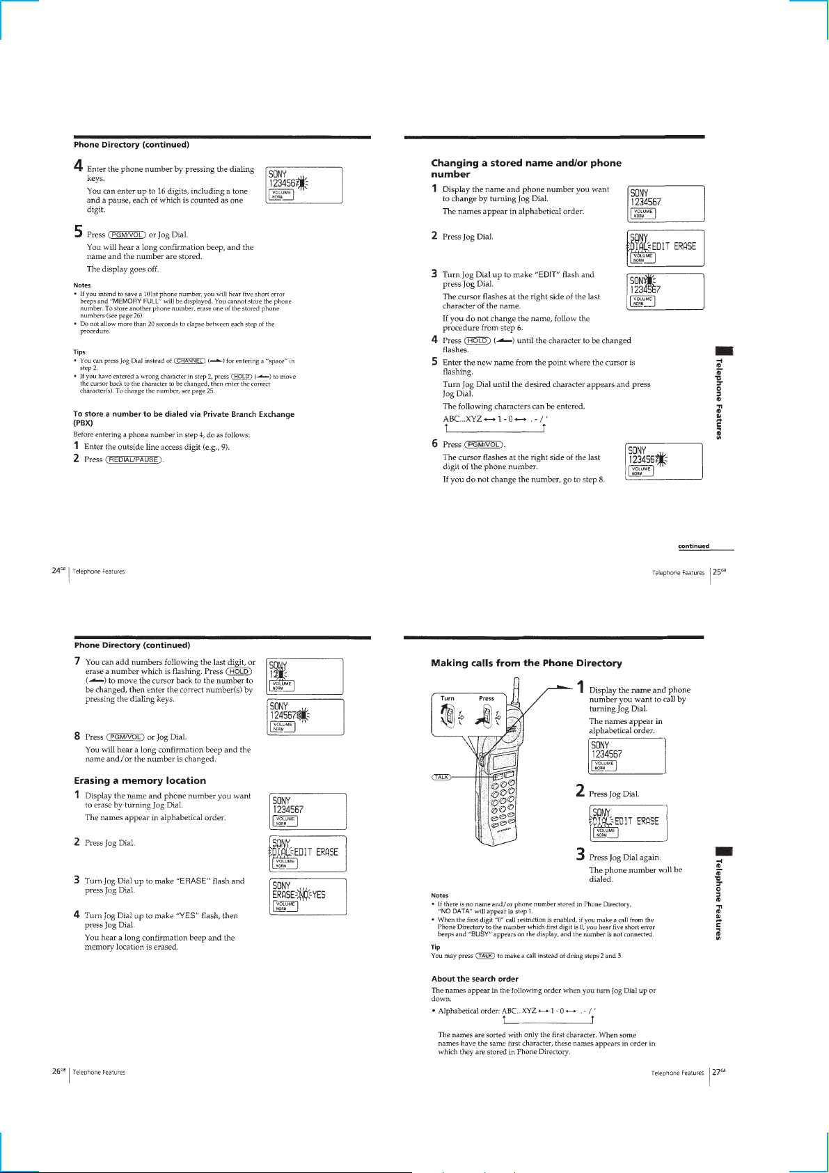
Phone Directory....................................................................... 7
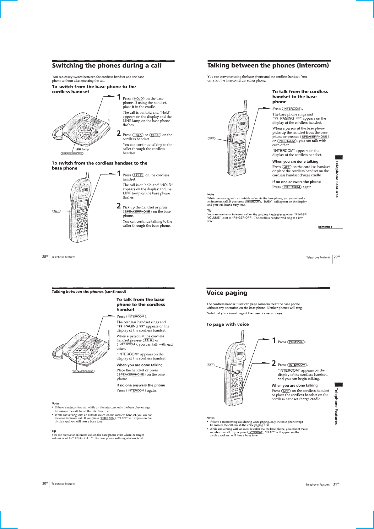
Switching the phones during a call.......................................... 9
Talking between the phones (Intercom) .................................. 9
Voice paging ............................................................................ 9
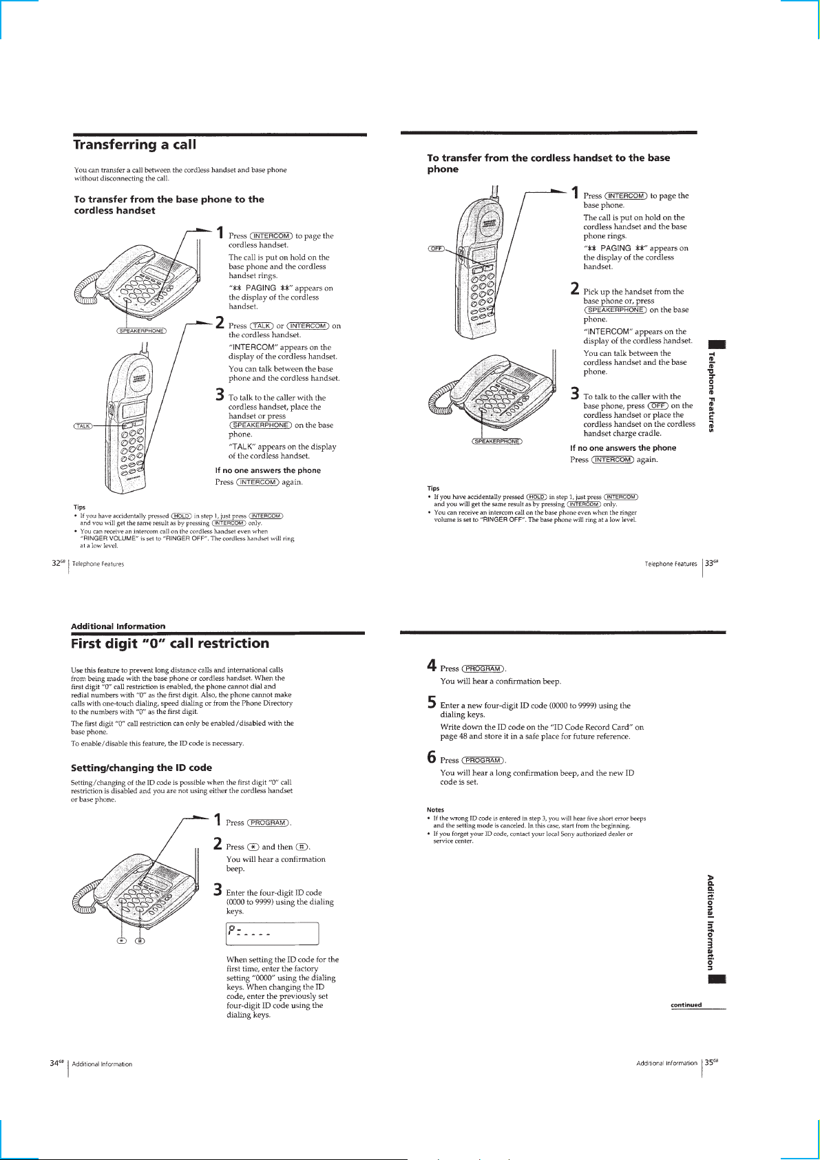
Transferring a call..................................................................10
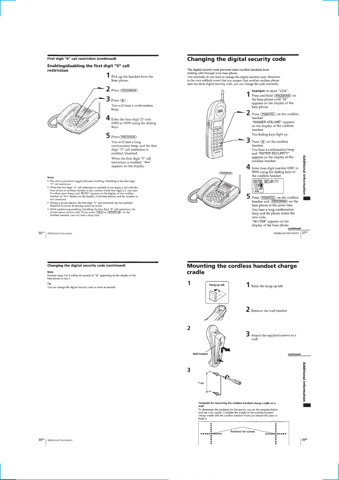
First digit “0” call restriction ................................................. 10
Changing the digital security code ........................................ 11
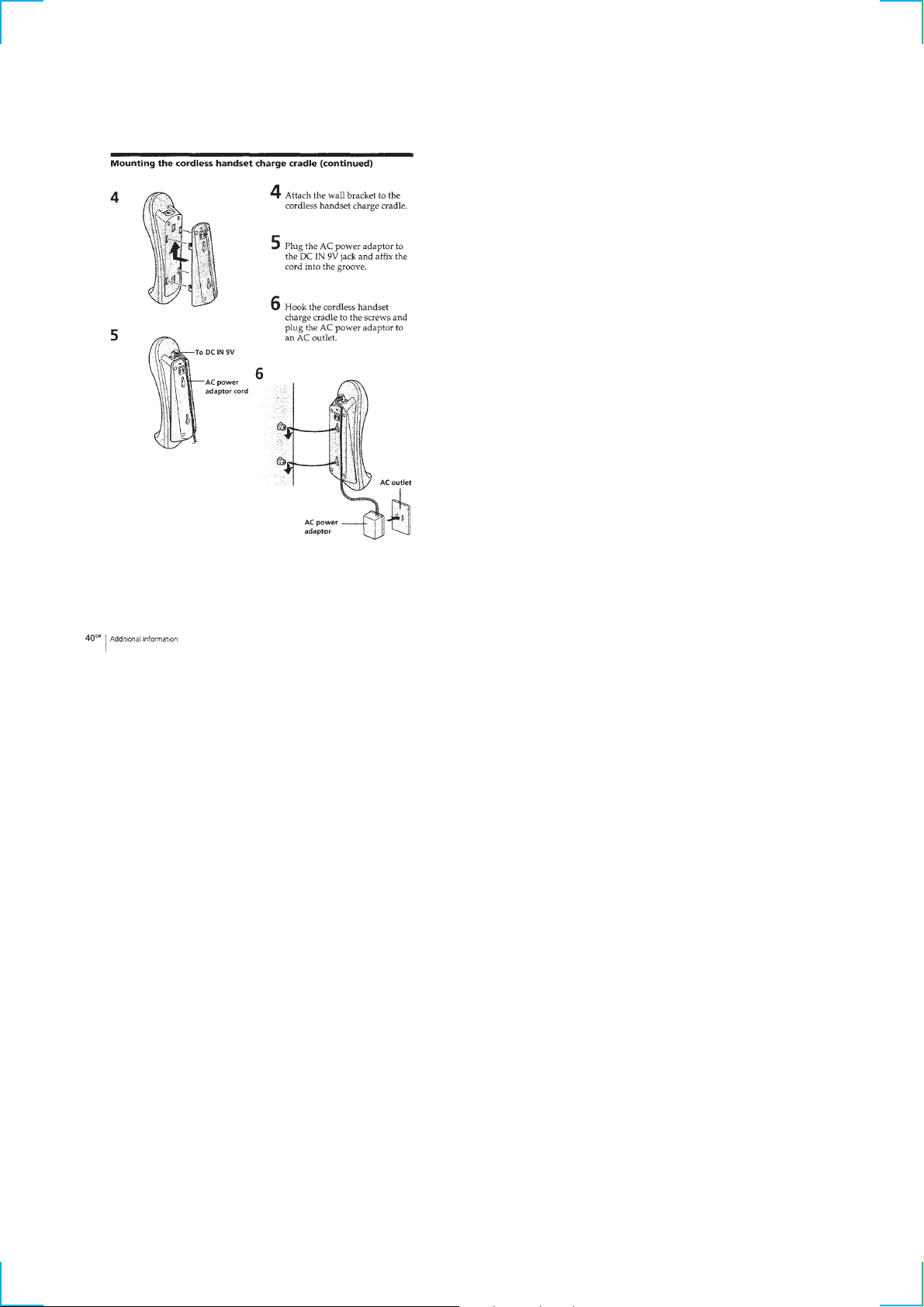
Mounting the cordless handset charge cradle........................ 11
2. DISASSEMBLY
2-1. Cabinet (Lower) ................................................................ 13
2-2. Base LCD Board ............................................................... 13
2-3. Base Key Board................................................................. 14
2-4. Base Mic Board................................................................. 14
2-5. Base Main Board............................................................... 15
2-6. Cabinet (Rear) ................................................................... 15
2-7. Hand Main Board .............................................................. 16
4. ELECTRICAL ADJUSTMENTS
Base Phone Section ............................................................... 22
Handset Section ..................................................................... 24
5. DIAGRAMS
5-1. IC Pin Description............................................................. 26
5-2. Block Diagram –Base Phone Section– ............................. 27
5-3. Block Diagram –Handset Section– ................................... 28
5-4. Printed Wiring Board –Base Key Section– ....................... 29
5-5. Schematic Diagram –Base Key Section–.......................... 29
5-6. Printed Wiring Boards –Base Main Section–.................... 30
5-7. Schematic Diagram –Base Main (1/3) Section– ............... 31
5-8. Schematic Diagram –Base Main (2/3) Section– ............... 32
5-9. Schematic Diagram –Base Main (3/3) Section– ............... 33
5-10. Printed Wiring Board –Base LCD Section–...................... 34
5-11. Schematic Diagram –Base LCD Section– ........................ 35
5-12. Printed Wiring Board –Hand Main Section– .................... 36
5-13. Schematic Diagram –Hand Main Section– ....................... 37
5-14. Printed Wiring Board –Hand Key Section– ...................... 38
5-15. Schematic Diagram –Hand Key Section–......................... 39
6. EXPLODED VIEWS
6-1. Base Phone Section ........................................................... 44
6-2. Handset Section................................................................. 45
7. ELECTRICAL PARTS LIST ........................................ 46
3. TEST MODE
Base Phone Section ............................................................... 17
Handset Section ..................................................................... 19
Notes on Chip Component Replacement
• Never reuse a disconnected chip component.
• Notice that the minus side of a tantalum capacitor may be dam-
aged by heat.
SAFETY-RELATED COMPONENT WARNING!!
COMPONENTS IDENTIFIED BY MARK ! OR DOTTED LINE
WITH MARK ! ON THE SCHEMATIC DIAGRAMS AND IN
THE PARTS LIST ARE CRITICAL TO SAFE OPERATION.
REPLACE THESE COMPONENTS WITH SONY PAR TS WHOSE
P ART NUMBERS APPEAR AS SHOWN IN THIS MANUAL OR
IN SUPPLEMENTS PUBLISHED BY SONY.
2
SECTION 1
GENERAL
This section is extracted
from instruction manual.
3
456789101112
0
SECTION 2
DISASSEMBLY
Note : Follow the disassembly procedure in the numerical order given.
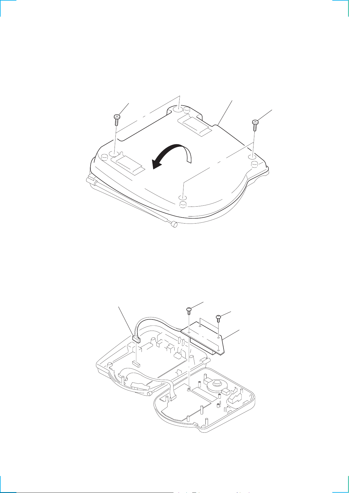
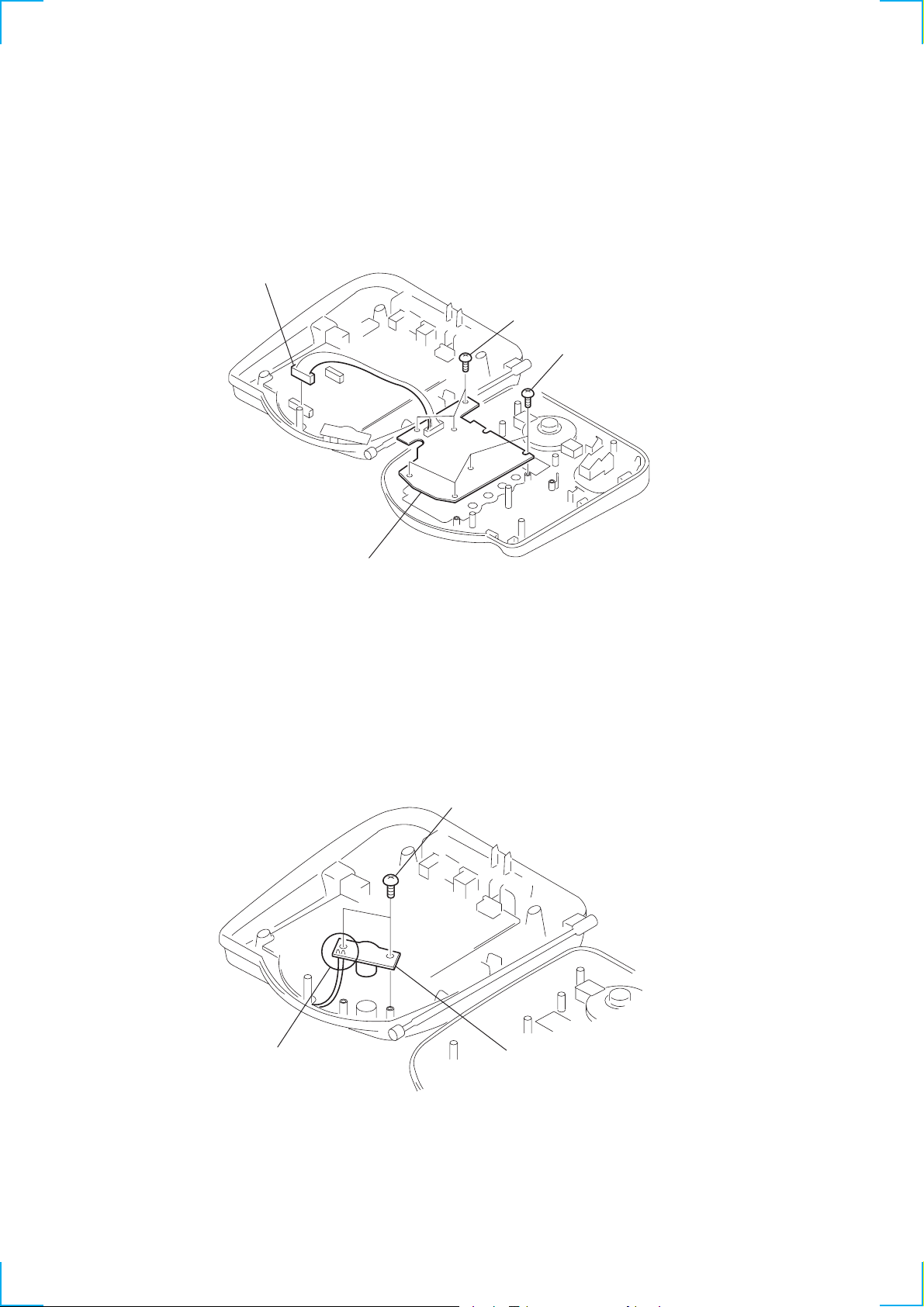
2-1. CABINET (LOWER)
2
P3x10
3
4
cabinet (lower)
1
P3x1
2-2. BASE LCD BOARD
1
CN301
2
BTP2.6x8
3
BTP2.6x8
4
BASE LCD board
13
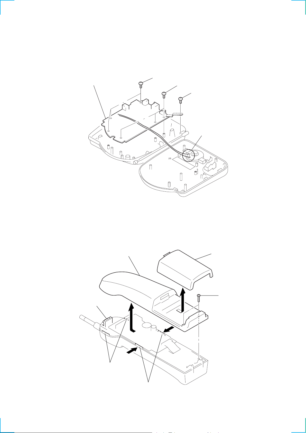
2-3. BASE KEY BOARD
1
CN302
4
BASE KEY board
2
BTP2.6x8
3
BTP2.6x8
2-4. BASE MIC BOARD
1
Unsolder the 2 places.
2
BTP2.6x8
3
BASE MIC board
14
2-5. BASE MAIN BOARD
5
BASE MAIN board
4
BTP2.6x8
3
BTP2.6x8
2
BTP2.6x8
1
Unsolder the 2 places.
2-6. CABINET (REAR)
5
claw
6
cabinet (rear)
4
claws
1
battery case lid (hand)
2
BTP 2.6x10
3
claws
15
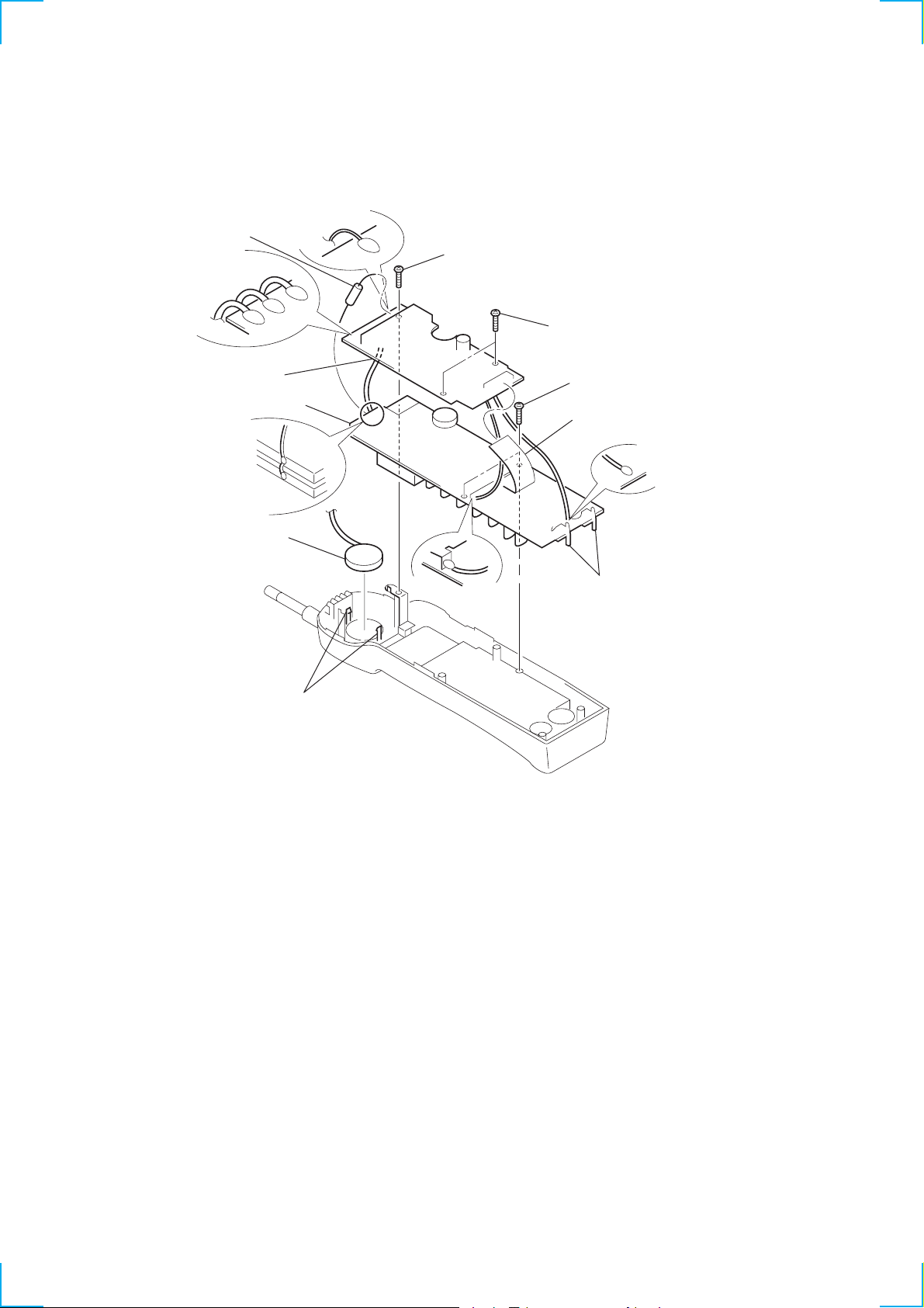
2-7. HAND MAIN BOARD
discharge gap (CP101)
4
Unsolder the
3 places.
9
HAND MAIN board
!™
HAND KEY board
8
Unsolder.
!¢
speaker
5
Unsolder.
3
BTP 2x8
2
BTP 2x8
0
1 CN3
BVTP 2x8
6
Unsolder.
!£
claws
7
Unsolder.
!¡
charge terminals (hand)
16
SECTION 3
TEST MODE
BASE PHONE SECTION
MANUAL TEST MODE
Set the Test Mode:
1. Set the DIAL MODE switch to “P” (pulse).
2. While pressing the INTERCOM key, insert the AC adaptor
(Reset start).
3. With the INTERCOM key, still held down, switch the
DIAL MODE switch “T” (tone) n “P” (pulse).
4. When the INTERCOM key is released, test mode starts.
Release the Test Mode:
1. Pull out the AC adaptor or turn off the power.
MACHINE TEST MODE
Set the Test Mode:
1. Connect between TP306 (TEST SW) and GND.
2. Set the Channel Setting terminal (See page 18.)
3. Turn on the power to start the test mode.
Release the Test Mode:
1. Pull out the AC adaptor or turn off the power.
2. Remove the short plug and turn on the power again.
OPERATION AT START OF TEST MODE
• The ringer sounds for 500 msec.
• Setting of channel: CH1 for manual test mode and the Channel
Setting terminal for machine test mode. (See page 18.)
• TX is set ON and the handset is allowed to call outside.
RSSI is set to Hi sensitivity.
• Liquid crystal display panel is turned ON for 1 sec. and then the
channel is displayed (for example, Ch1 CH1=01). LINE LED
and back light are to be still ON. The pulse dial “0” is output
once.
OPERATION IN TEST MODE
• In test mode, RSSI is continuously monitored. LINE LED is turned
ON with RSSI (Low) and OFF without RSSI (High).
• In test mode, any key input is continuously monitored. Each key
input causes the set to switch to the state as listed below.
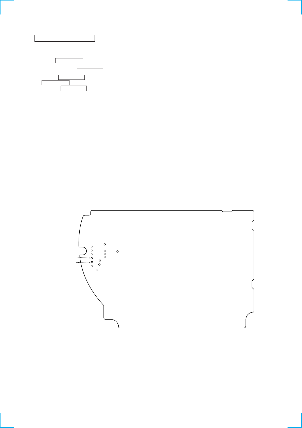
TP337
TP335
– base main board (conductor side) –
TP320
TP306
TP336
TP334
17
 Loading...