

Sony SPP-801, SPP-811, SPP-851, SPP-861 Service Manual
SPP-801/811/851/861
MICROFILM
SERVICE MANUAL
Ver 1.1 2000. 11
With SUPPLEMENT-1
(9-927-610-81)
Photo: SPP-851
SPECIFICATIONS
General
Frequency control Crystal-controlled PLL
Operation mode FM, duplex
Operation channel 10 channels
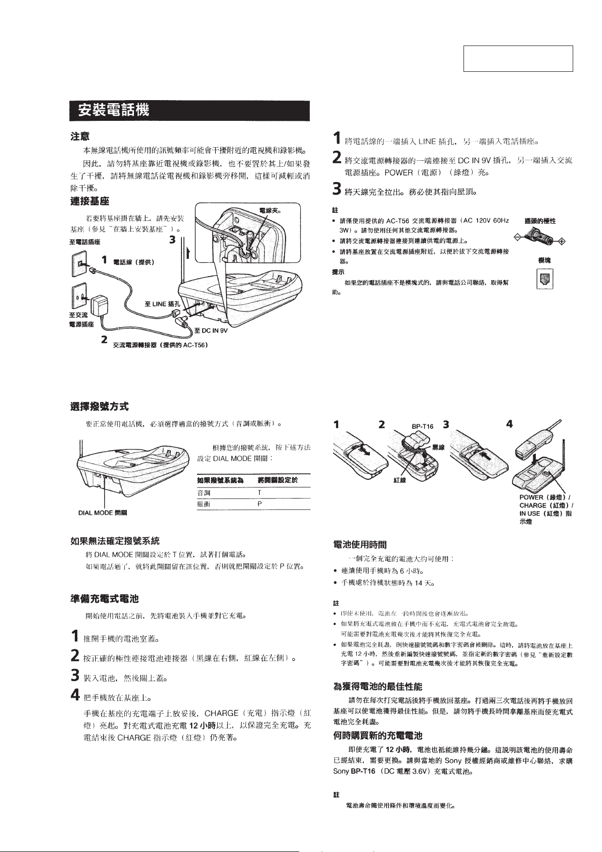
Supplied accessories AC power adaptor AC-T56 (1)
Telephone line cord (1)
Rechargeable battery pack BP-T16 (1)
Screws (2)
Directories (2 sheets)
Taiwan Model
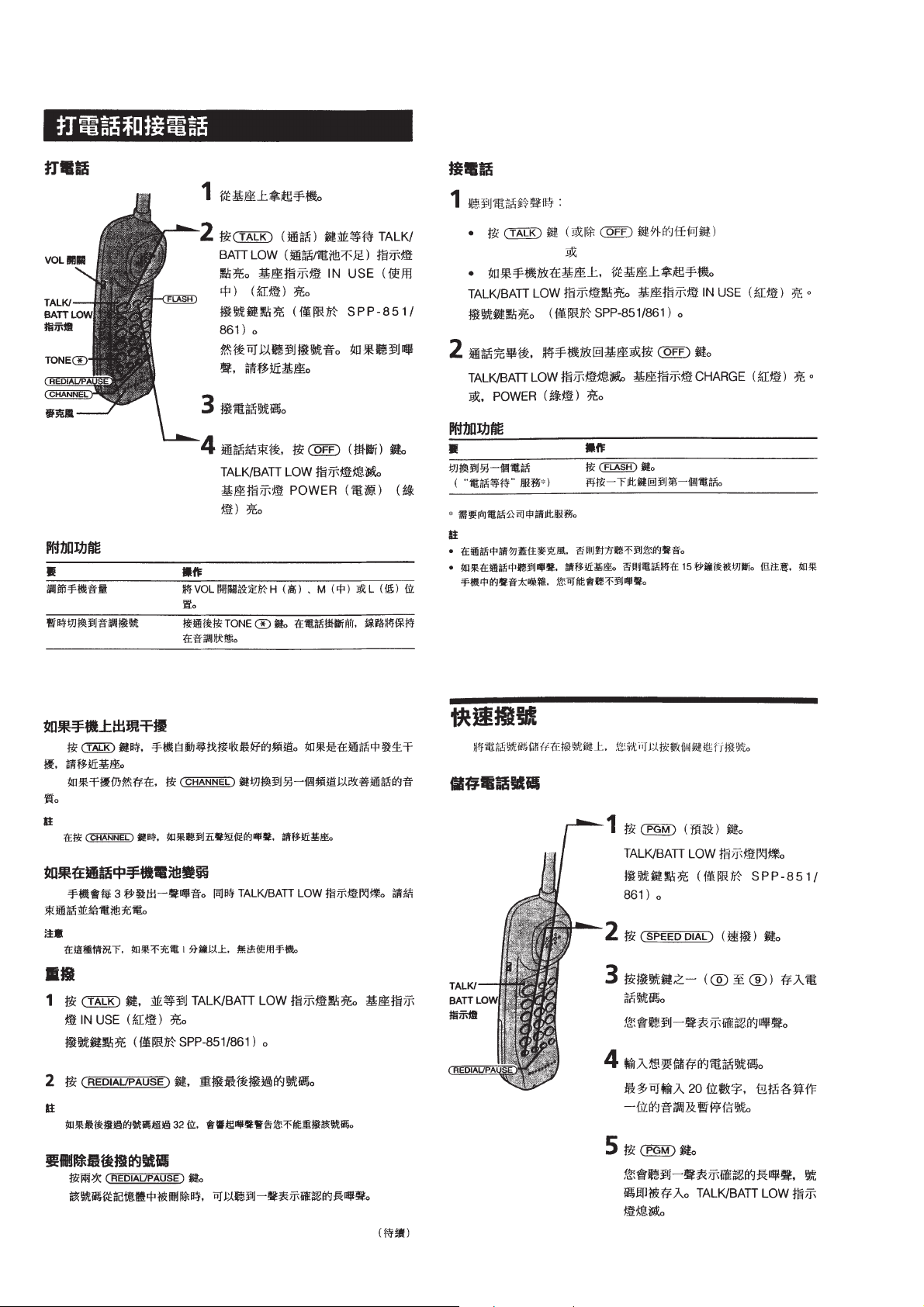
Handset
Power source Rechargeable battery pack BP-T16
Battery life Standby: Approx. 14 days
Dimensions Approx. 58 × 194 × 47
Mass Approx. 220 g, battery included
Base unit
Power source DC 9V from AC power adaptor
Battery charging time Approx. 12 hours
Dimensions Approx. 132 × 56 × 220 mm (w/h/d), antenna
Mass Approx. 310 g
Design and specifications are subject to change without notice.
Talk: Approx. 6 hours
excluded
Antenna: Approx. 110 mm
excluded
Antenna: Approx. 310 mm
mm (w/h/d), antenna
CORDLESS TELEPHONE
– 1 –

TABLE OF CONTENTS
1. GENERAL ........................................................................... 3
2. DISASSEMBLY
2-1. Cabinet (Lower) (Base Unit)............................................... 6
2-2. Cabinet (Rear) (Handset) ....................................................6
3. TEST MODE
Base Unit Section ....................................................................7
Handset Section ....................................................................... 9
4. ELECTRICAL ADJUSTMENTS
Base Unit Section ..................................................................12
Handset Section ..................................................................... 14
5. DIAGRAMS
5-1. IC Pin Descriptions ...........................................................16
5-2. Block Diagram –Base Unit Section– ................................19
5-3. Block Diagram –Handset Section– ................................... 21
5-4. Printed Wiring Board –Base Unit Section– ......................23
5-5. Schematic Diagram –Base Unit Section– .........................25
5-6. Printed Wiring Board –Handset Section– ......................... 27
5-7. Schematic Diagram –Handset Section– ............................ 29
6. EXPLODED VIEWS
6-1. Base Unit Section .............................................................. 32
6-2. Handset Section................................................................. 33
7. ELECTRICAL PARTS LIST ........................................ 34
Notes on Chip Component Replacement
• Never reuse a disconnected chip component.
• Notice that the minus side of a tantalum capacitor may be dam-
aged by heat.
SAFETY-RELATED COMPONENT WARNING!!
COMPONENTS IDENTIFIED BY MARK ! OR DOTTED LINE
WITH MARK ! ON THE SCHEMATIC DIAGRAMS AND IN
THE PARTS LIST ARE CRITICAL TO SAFE OPERATION.
REPLACE THESE COMPONENTS WITH SONY PARTS WHOSE
P AR T NUMBERS APPEAR AS SHO WN IN THIS MANUAL OR
IN SUPPLEMENTS PUBLISHED BY SONY.
– 2 –
SECTION 1
GENERAL
This section is extracted
from instruction manual.
– 3 –
– 4 –
– 5 –
)
)
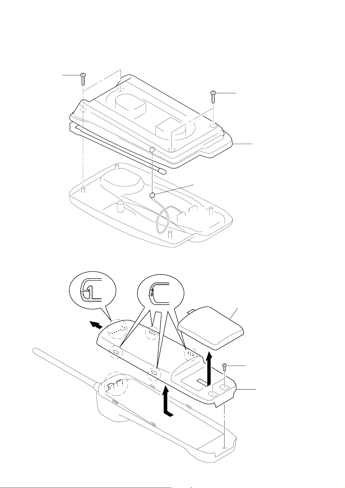
SECTION 2
DISASSEMBLY
Note : Follow the disassembly procedure in the numerical order given.
2-1. CABINET (LOWER) (BASE UNIT)
1
P 3x10
3
connector (CN301)
2
P 3x10
4
cabinet (lower
2-2. CABINET (REAR) (HANDSET)
4
claw
3
claws
1
battery case lid assy
2
BTP 2.6x10
5
cabinet (rear
– 6 –
SECTION 3
TEST MODE
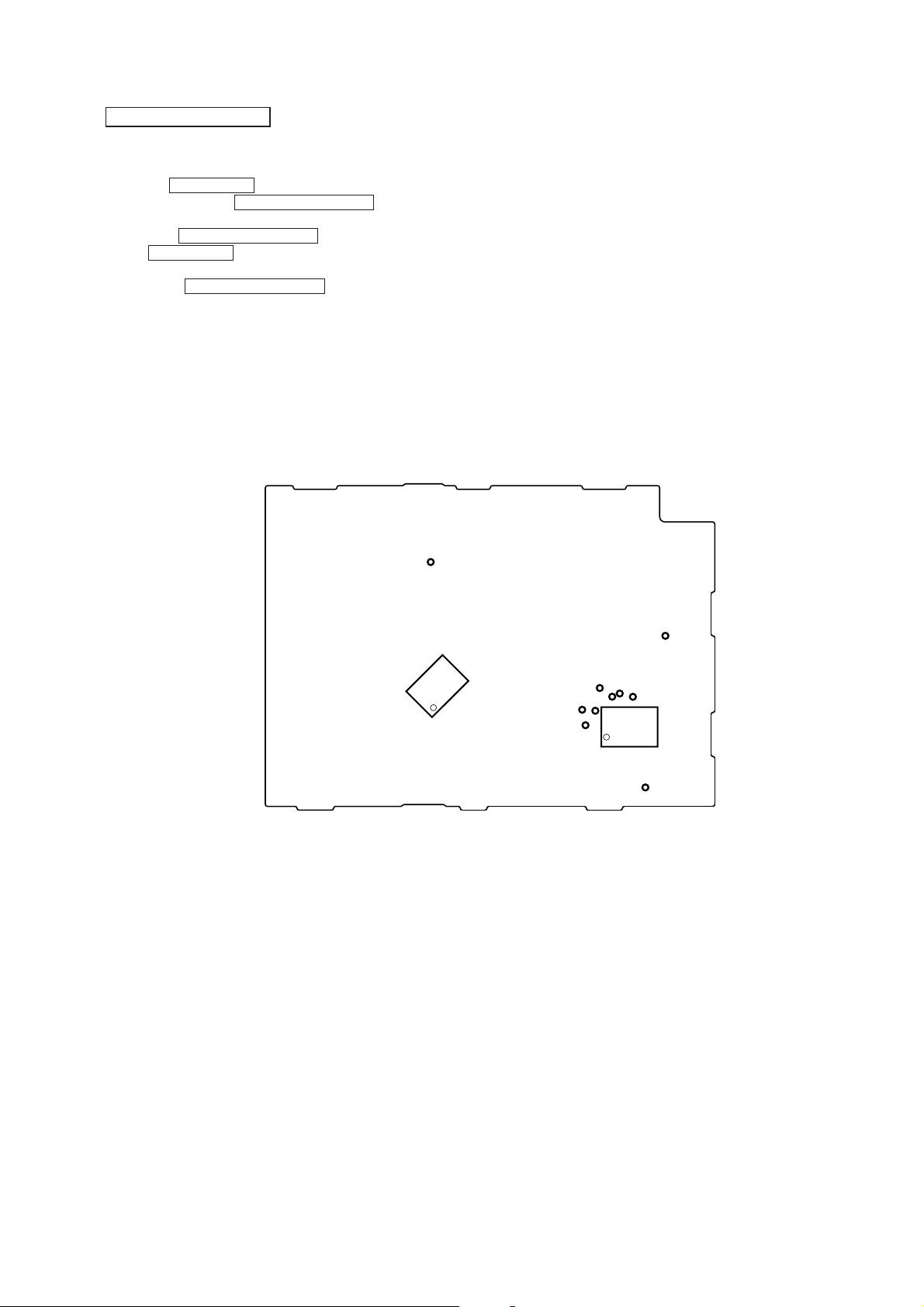
BASE UNIT SECTION
MANUAL TEST MODE
Set the Test Mode:
1. Set the DIAL MODE switch to “P” (pulse).
2. While pressing the HANDSET LOCATOR key, insert the AC
adaptor (Reset start).
3. With the HANDSET LOCATOR key, still held down, switch
the DIAL MODE switch “P” (pulse) n “T” (tone) n
“P” (pulse).
4. When the HANDSET LOCATOR key is released, test mode
starts.
5. Firstly, “0” will be dialled out at 10 pps. Then “1”, “4”, “8”
and “#” will be sent out by DTMF.
6. Set to TX ON. Goes to external line state in 1 CH.
Release the Test Mode:
1. Pull out the AC adaptor or turn off the power.
– base main board (conductor side) –
TP46
MACHINE TEST MODE
Set the Test Mode:
1. With one of the CH setting terminals in “H” input state,cause
Reset of Power ON. Equipment enters machine test mode.
2. Setting of CH according to logic input with CH setting
terminal.
3. ON/OFF of TX is according to the input logic of the DIAL
MODE terminal.
Release the Test Mode:
1. Pull out the AC adaptor or turn off the power.
2. Remove the short plug and turn on the power again.
IC101
TP65
TP64
TP66
TP63
TP47
TP62
TP61
TP67
IC501
TP106
– 7 –
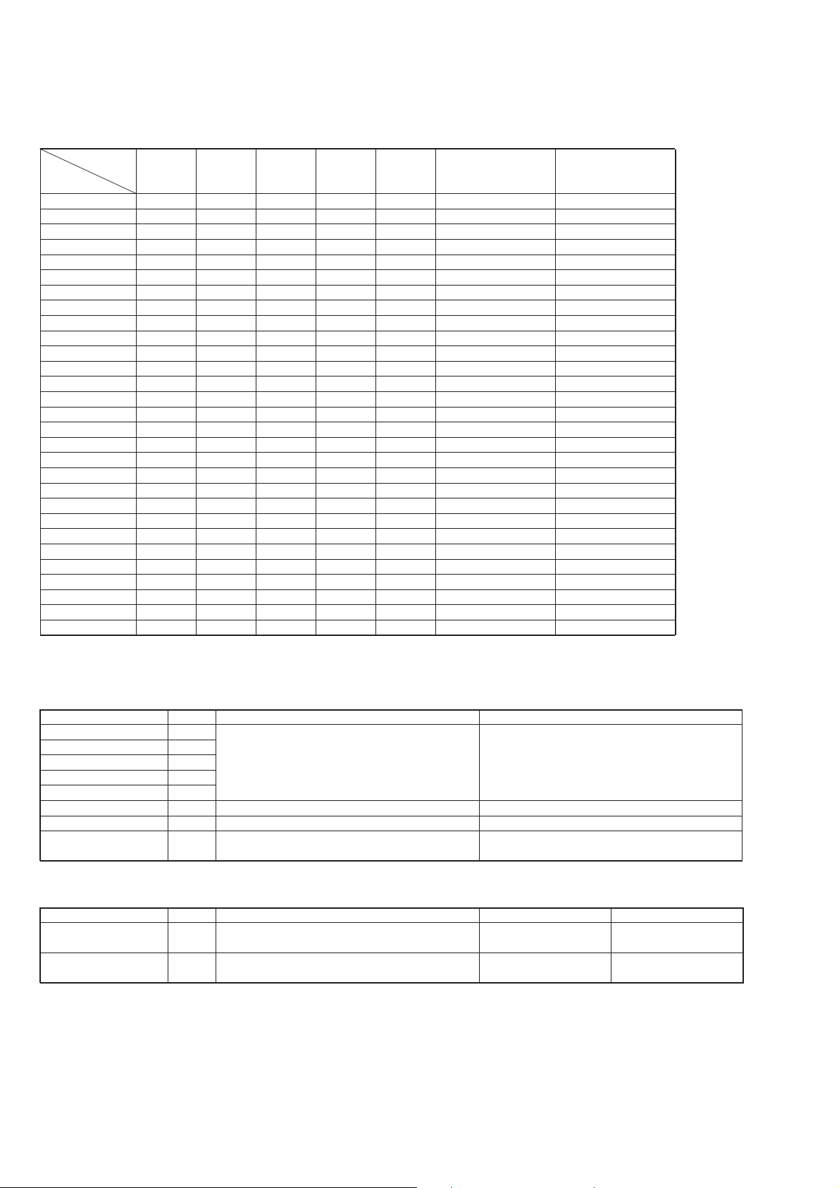
Channel Setting:
During startup in machine test mode, make the following channel
settings by loading the terminal input data.
Pin No.
Channel
CH1 H L L L 43.720 48.760
CH2 L H L L 43.740 48.840
CH3 H H L L 43.820 48.860
CH4 L L H L 43.840 48.920
CH5 43.920 49.020
CH6 43.960 49.080
CH7 44.120 49.100
CH8 44.160 49.160
CH9 44.180 49.200
CH10 44.200 49.240
CH11 44.320 49.280
CH12 44.360 49.360
CH13 44.400 49.400
CH14 H L H L 44.460 49.460
CH15 L H H L 44.480 49.500
CH16 H H H L 46.610 49.670
CH17 L L L H 46.630 49.845
CH18 46.670 49.860
CH19 46.710 49.770
CH20 46.730 49.875
CH21 46.770 49.830
CH22 46.830 49.890
CH23 H L L H 46.870 49.930
CH24 L H L H 46.930 49.990
CH25 H H L H 46.970 49.970
TEST1 L L H H 43.780 48.800
TEST2 H L H H 43.890 48.970
TEST3 L H H H 46.800 49.910
TEST4 H H H H 46.900 49.950
23 24 25 26
M1 M2 M3 M4
(TP61) (TP62) (TP63) (TP64)
TX frequency RX frequency
(MHz) (MHz)
Machine Test Mode Input / Output:
1. Input (Input ports for other than main tasks)
Pin Name Pin No. Function Logic
M1 (TP61) 23
M2 (TP62) 24
M3 (TP63) 25
M4 (TP64) 26
DIAL MODE
(TP47)
HANDSET LOCATOR
(TP46)
29 28 27
TEST1 TEST2 TEST3 Operation with CHARGE LED Operation with TX ON
(TP67) (TP66) (TP65)
L L L If RSSI (H) is detected : Light ON If RSSI (H) is detected : Light ON
L L H If RSSI (L) is detected : Light ON If RSSI (L) is detected : Light ON
L H L If TX LOCK is detected : Light OFF If TX LOCK is detected : Light OFF
L H H If RX LOCK is detected : Light OFF If RX LOCK is detected : Light OFF
H L L BEEP output
H L H ID CODE output
H H L If RING is detected : Light ON If RING is detected : Light ON
H H H If HANDSET LOCATOR key is input : Light ON If HANDSET LOCATOR key is input : Light ON
Setting the CH (channel) Refer to channel setting
17 Setting the TX ON/OFF TONE : open, PULSE : short
Manual : Channel increment Incrementing of channels in order from 1 to 10.
16 Machine : Dial data “5” is output to Key input with “L” input.
DTMF/DP exchange The first time there is output of “5” with DTMF.
2. Output (Output ports for other than main tasks)
Pin Name Pin No. Function H Logic L Logic
CHARGE DET (TP21) 18 State in section 1. Input Refer to section 1. Input
– 8 –
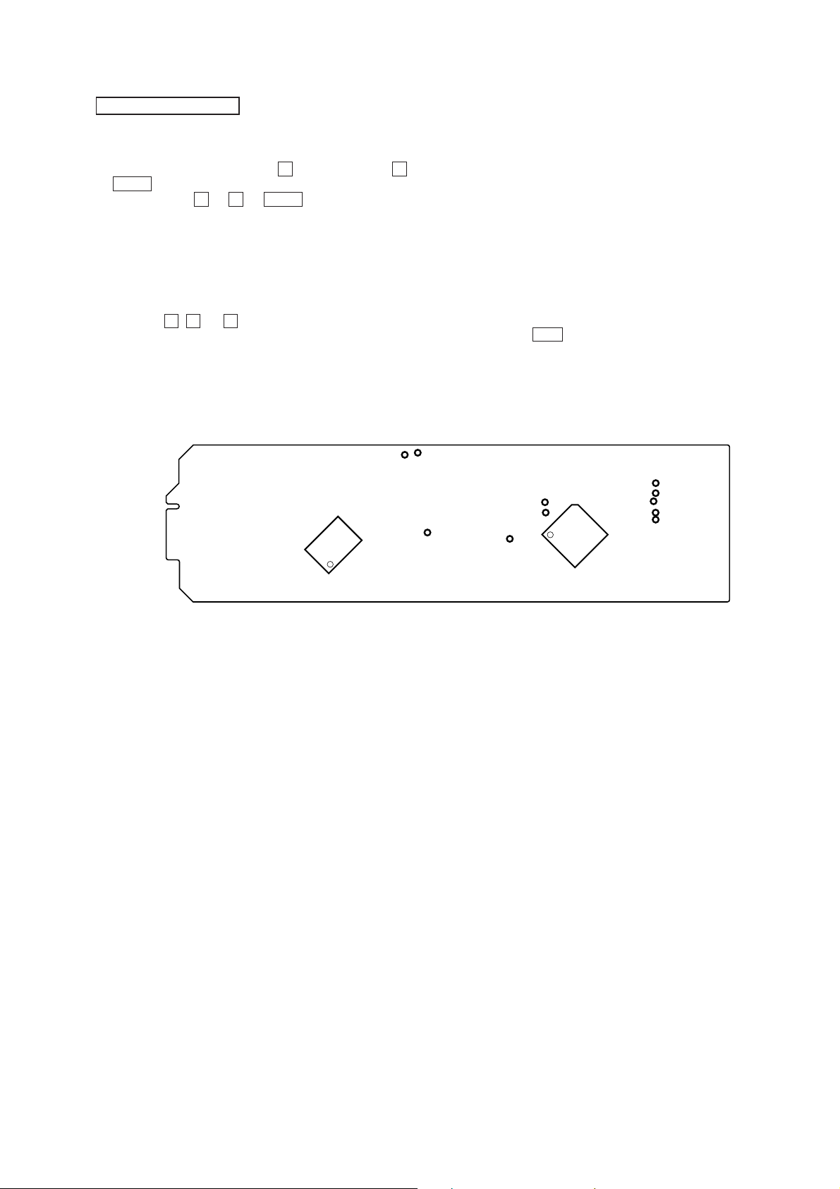
HANDSET SECTION
MANUAL TEST MODE
Set the Test Mode:
1. Enter the test mode by pressing 0 key while pressing 1 and
TALK keys when in idle condition.
(Key operation 0 n 1 n TALK )
2. The RINGER will ring for 500 msec. when the test mode is
started.
3. Measurement mode of consumption current. (42# state)
4. Use key input to carry out the various settings.
5. Use port inputs to set output from LED terminals.
Release the Test Mode:
1. Press the 0 , 0 and # keys.
2. Turn off the power. (Remove the battery and replace them.)
– hand main board (side B) –
TP35
TP55
IC101
MACHINE TEST MODE
Set the Test Mode:
1. When power on reset is applied while a “H” (high) is input the
TEST SW (TP43) terminal (IC501 $º pin), the RING (Level
H, 500 msec) sounds.
2. Following that, at timing in which the TEST SW terminal has
“H” (high) input, there is output of “L” (low) by the CH
(channel) setting control terminal. Then there is PLL setting to
the CH which was read to with the CH setting terminal
according to that “L” (low) output.
3. Set the TX setting to TX OFF.
4. The channel is set by voice not by data.
5. Use port inputs to set output from LED terminals.
Release the Test Mode:
1. Press the OFF key.
2. Remove the short plug and turn on the power.
TP36
TP13
TP43
TP44
TP33
IC501
TP14
TP16
TP15
TP17
– 9 –
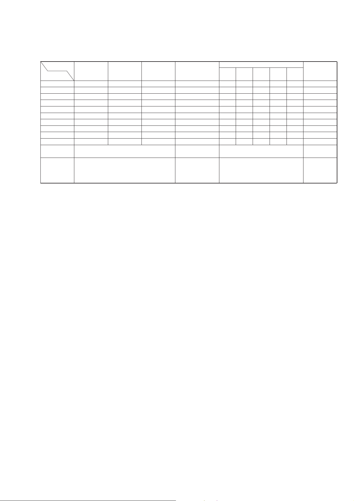
Channel Setting:
During startup in machine test mode, make the following channel
settings by loading the terminal input data.
Pin No.
Channel
CH1 H L L L L 48.760 43.720
CH2 H L L L H 48.840 43.740
CH3 H L L H L 48.860 43.820
CH4 H L L H H 48.920 43.840
CH5 H L H L L 49.020 43.920
CH6 H L H L H 49.080 43.960
CH7 H L H H L 49.100 44.120
CH8 H L H H H 49.160 44.160
CH9 H H L L L 49.200 44.180
CH10 H H L L H 49.240 44.200
CH11 H H L H L 49.280 44.320
CH12 H H L H H 49.360 44.360
CH13 H H H L L 49.400 44.400
CH14 H H H L H 49.460 44.460
CH15 H H H H L 49.500 44.480
CH16 L L H H L 49.670 46.610
CH17 L L H H H 49.845 46.630
CH18 L H L L L 49.860 46.670
CH19 L H L L H 49.770 46.710
CH20 L H L H L 49.875 46.730
CH21 L H L H H 49.830 46.770
CH22 L H H L L 49.890 46.830
CH23 L H H L H 49.930 46.870
CH24 L H H H L 49.990 46.930
CH25 L H H H H 49.970 46.970
TEST1 L L L H L 48.800 43.780
TEST2 L L L H H 48.970 43.890
TEST3 L L H L L 49.910 46.800
TEST4 L L H L H 49.950 46.900
34 33 32 31 29
ROW5 ROW4 ROW3 ROW2 ROW1
(TP13) (TP14) (TP15) (TP16) (TP17)
TX frequency RX frequency
(MHz) (MHz)
Machine Test Mode Input / Output:
1. Input (Input ports for other than main tasks)
Pin Name Pin No. Function Logic
ROW1 (TP17) 29
ROW2 (TP16) 31
ROW3 (TP15) 32 Setting the CH (channel) Refer to channel setting
ROW4 (TP14) 33
ROW5 (TP13) 34
TEST CH (TP33) 1 Control terminal for setting the CH (channel) H : OFF, L : ON
TEST SW (TP43) 40 Start up of the test mode H : Start, L : Not start
TEST ACK (TP44) 44
2. Output (Output ports for other than main tasks)
Pin Name Pin No. Function H Logic L Logic
T ALK LED (TP35) 48
KEY LED (TP55) 2
During the test mode, causes start of intermittent
operation with external input.
Various input/output monitor output
(default : RSSI (H) detection).
During test mode : All light lit. However, does
not include measurment of consumption current.
H : Intermittent start
No detection Detection
No light Light
– 10 –
Key Processing (Setting the Manual Test Mode) :
1. (Upper position) (Lower position) Set with #.
2. 3X# can be substituted with X .
Upper position
Lower position
0 QUIT 10 ch 20 ch Batt Alarm H A L T G KEY TEST
1 1 ch 11 ch 21 ch CHARGE DET GgGGG
2 2 ch 12 ch 22 ch GggGG
3 3 ch 13 ch 23 ch ggGGG
4 4 ch 14 ch 24 ch RX LOCK gggGG
5 5 ch 15 ch 25 ch TX LOCK ggggG
6 6 ch 16 ch T1 ch RSSI (H) ggggg
7 7 ch 17 ch T2 ch RSSI (L) —————
8 8 ch 18 ch T3 ch DATA TX —————
9 9 ch 19 ch T4 ch —————
Purpose CH setting only SIGOUT control
Application
• By pressing the CH key there is increment of the channel.
However, this does not include the test channel.
• Control of the power source during 38# DATA TX is (TX & RX
RF & RX AF=ON) in 44# state.
• Control of the power source during the 70# key check mode is
41# state (TX OFF).
• For CH setting, SIGOUT control and power source control (with
the exception of above-mentioned 38# state) the state can be set
independently.
Example : In 15 ch, the order for carrying out TX modulation
level and RSSI (H) sensitivity setting is as follows :
The following are possible :15# n 44# n 36#
012 3TXRX RX
The standard is external communication
state.
State for standard electrical adjustment
process.
*
36# n 15# n 44#
44# n 36# n 15#
Condition
surveillance with
T ALK LED.
4
RF AF
Measurement mode of
consumption current.
g : ON, G : OFF
MIC Lk
7
General
operation
– 11 –
)
)
SECTION 4
ELECTRICAL ADJUSTMENTS
BASE UNIT SECTION
Note:
• Apply 9V dc from regurated DC power supply.
• Perform the adjustment at TEST3CH (28CH: 49.910 MHz) as a
rule.
• Set to base unit manual test mode. (Refer to page 7)
• Switch position :
S302 (DIAL MODE) : P (pulse)
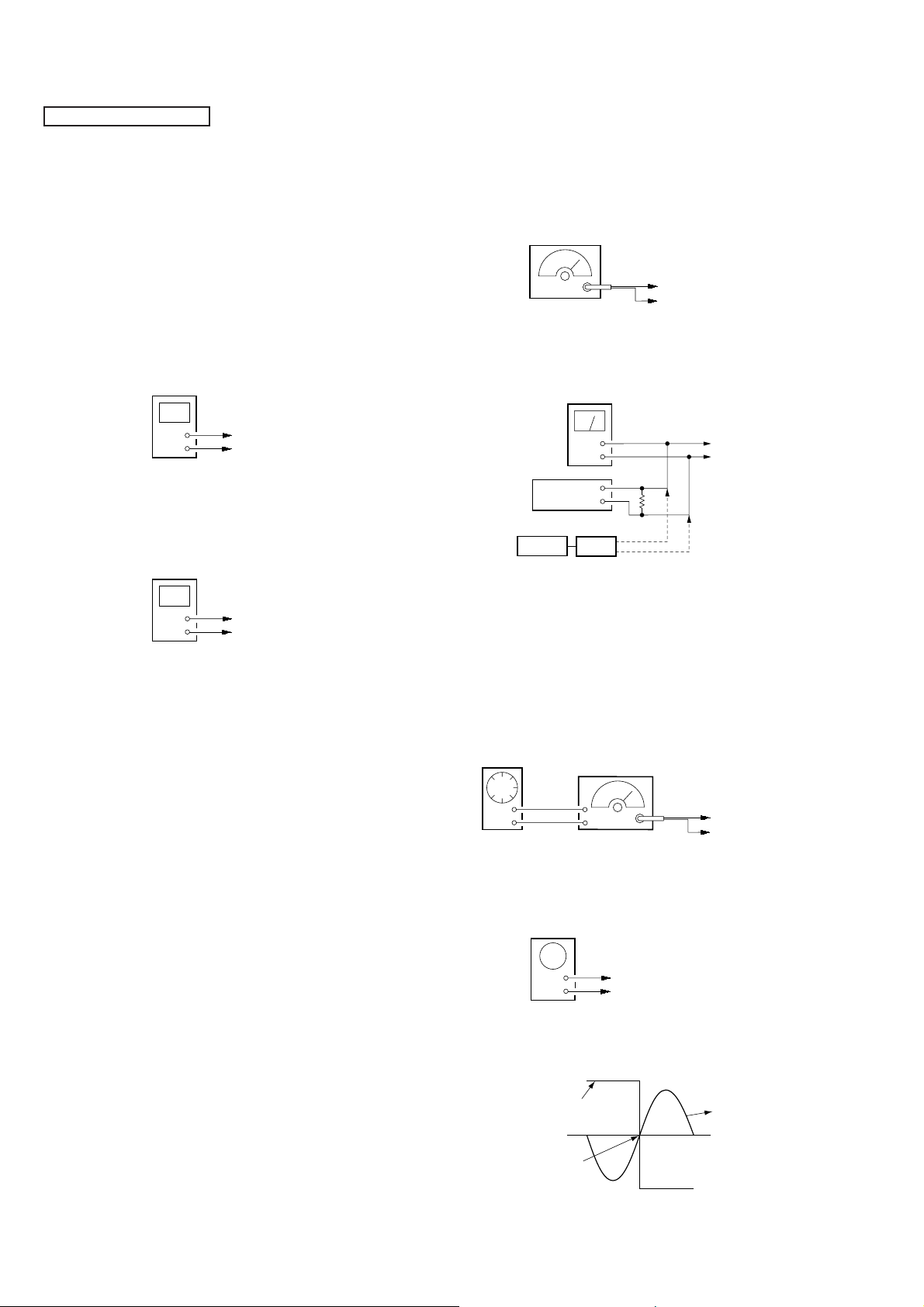
TX SECTION ADJUSTMENT
• The electrolytic capacitor (10 µF/10 V) connected TP23 (DET
OUT) to TP19 (GND). (Only TX section adjustment)
TX VT Adjustment
Setting :
Procedure :
1. The digital voltmeter connected TP6 (TX VT) to TP19 (GND).
2. Adjust the L52 for 2.2 ± 0.05 V reading on the digital voltmeter.
RX VT Adjustment
Setting :
Procedure :
1. The digital voltmeter connected TP5 (RX VT) to TP3
(RX GND).
2. Adjust the L101 for 2.4 ± 0.05 V reading on the digital voltmeter .
digital voltmeter
+
–
digital voltmeter
+
–
TP6 (TX VT)
TP19 (GND)
TP5 (RX VT)
TP3 (RX GND)
RX SECTION ADJUSTMENT
RX LEVEL Adjustment
Note:
• Perform the adjustment at TEST3CH (28CH: 49.910 MHz) as a
rule.
Setting :
FM RF
signal generator
TP2
TP3 (RX GND
Carrier frequency : 49.910 MHz
Modulation : 1 kHz
Deviation : FM 3 kHz
Output level : 60 dBµV (1 mV) (EMF)
level meter
PBX tester
DC 48V
+
–
Ω
600
or
F.B.
TP105
TP104
Procedure :
1. Adjust the FL101 for the maximam reading on the level meter.
Also check that the output level is the specified values.
Specified V alue : –1.4 to –9.6 dBV
RSSI Hi Adjustment
Note:
• Perform the adjustment at TEST3CH (28CH: 49.910 MHz) as a
rule.
Setting :
AF oscillator
FM RF
signal generator
TP2
Output: 20 Hz
oscilloscope
(DC range)
Carrier frequency : 49.910 MHz
Modulation : 20 Hz (EXT)
Deviation : AM 50%
Output level : 17 dBµV (7.1 µV) (EMF)
+
–
TP9 (SIG OUT)
TP19 (GND)
TP3 (RX GND
Procedure :
1. Use the oscilloscope to confirm the FM RF signal generator
input (AF) signal waveform and RSSI signal, and use the R V101
so that they are synchronized (duty is synchronized).
RSSI output waveform
0 V
Adjust so that they
synchronize at 0 V.
RSSI WAVEFORM
AF oscillator
EXT signal
20 Hz
Adjustment Location : base main board (See page 13)
– 12 –
 Loading...