

Sony SNT-V304 User Manual

Video Netw ork
Station
3-204-941-11(1)
User’s Guide Page 2
Guide de l’utilisateur Page 46
GB
FR
SNT-V304
2000 Sony Corporation
English
WARNING
To prevent fire or shock hazard, do not
expose the unit to rain or moisture.
To avoid electrical chock, do not open the
cabinet. Refer servicing to qualified
personnel only.
For the customers in the USA
This equipment has been tested and found to comply with
the limits for a Class B digital device, pursuant to Part 15 of
the FCC Rules. These limits are designed to provide
reasonable protection against harmful interference in a
residential installation. This equipment generates, uses, and
can radiate radio frequency energy and, if not installed and
used in accordance with the instructions, may cause harmful
interference to radio communications. However, there is no
guarantee that interference will not occur in a particular
installation. If this equipment does cause harmful
interference to radio or television reception, which can be
determined by turning the equipment off and on, the user is
encouraged to try to correct the interference by one or more
of the following measures:
— Reorient or relocate the receiving antenna.
— Increase the separation between the equipment and
receiver.
— Connect the equipment into an outlet on a circuit different
from that to which the receiver is connected.
— Consult the dealer or an experienced radio/TV technician
for help.
You are cautioned that any changes or modifications not
expressly approved in this manual could void your authority
to operate this equipment.
Voor de klanten in Nederland
• Dit apparaat bevat een MnO2-Li batterij voor memory back-up.
• De batterij voor memory back-up van het geheugen is
bevestigd op Z5601 van platt PW-1.
• Raadpleeg uw leverancier over de verwijdering van de
batterij op het moment dat u het apparaat bij einde
levensduur afdankt.
• Gooi de batterij niet weg, maar lever hem in als KCA.
• Bij dit produkt zijn batterijen geleverd. Wanneer deze leeg
zijn, moet u ze niet weggooien maar inleveren als KCA.
CAUTION
Danger of explosion if battery is incorrectly replaced.
Replace only with the same or equivalent type
recommended by the manufacturer.
Discard used batteries according to the manufacturer’s
instructions.
ADVARSEL!
Lithiumbatteri - Eksplosionsfare ved fejlagtig håndtering.
Udskiftning må kun ske med batteri af samme fabrikat og type.
Levér det brugte batteri tilbage til laverandøren.
ADVARSEL
Eksplosjonsfare ved feilaktig skifte av batteri.
Benytt samme batteritype eller en tilsvarende type
anbefalt av apparatfabrikanten.
Brukte batterier kasseres i henhold til fabrikantens
instruksjoner.
This device requires shielded interface cable to comply with
FCC emission limits.
Explosionsfara vid felaktigt batteribyte.
Använd samma batterityp eller en ekvivalent typ som
rekommenderas av apparattillverkaren.
Kassera använt batteri enligt fabrikantens instruktion.
VARNING
VAROITUS
Paristo voi räjähtää, jos se on virheellisesti asennettu.
Vaihda paristo ainoastaan laitevalmistajan suosittelemaan
tyyppiin.
Hävitä käytetty paristo valmistajan ohjeiden mukaisesti.
The operating system in the video network station is based upon the Linux 2.0 kernel, the source code of which is available at
http://developer.axis.com/download/elinux.
Microsoft, MS-DOS, Windows, Windows NT and ActiveX are registered trademarks of Microsoft Corporation in the USA and
other countries.
The names of other companies and products mentioned in this document are trademarks or registered trademarks of their
respective companies.

Table of Contents
Video Network Station Features ...................................... 4
Part Names and Functions ............................................... 5
Front Panel ..............................................................................5
Rear Panel ...............................................................................6
System Application Examples ......................................... 7
Installation.......................................................................... 8
Connections.............................................................................8
IP Address Assignment...........................................................8
Confirming Installation ...........................................................9
Settings ............................................................................ 11
Basic Settings with the First Time Installation Wizard ........11
Accessing the Administration Overview Page......................12
Monitor Screen and Alarm Function Setup ..........................13
Network Settings...................................................................14
System Administration and Security.....................................15
Serial Port Settings................................................................18
Video Input Setup .................................................................23
Accessing the Monitor Screen ..............................................25
Operation.......................................................................... 25
Camera View Operations ......................................................26
Pan/Tilt/Zoom Control..........................................................28
Viewing Alarm Event Images...............................................29
HSR View Mode...................................................................33
Basic Administration....................................................... 36
Log File Information.............................................................36
Resetting to Factory Defaults................................................37
Simultaneous Alarm Input to the HSR-1/1P/2/2P and Video
Network Station Alarm Memory .....................................38
If You Suspect a Problem .....................................................40
Lithium Battery Replacement ...............................................40
GB
English
Basic Specifications........................................................ 41
Settings List ..................................................................... 44
Warranty Card and After Sales Service......................... 45
Warranty Card.......................................................................45
After Sales Service................................................................45
Table of contents 3

Video network station Features
Video Network Station Features
This unit is a video network station that distributes real-time CCTV images over a LAN or the Internet.
Simple monitoring over a network
•By assigning an IP address to this unit, live video can
be monitored using standard Web browsers on client
PCs.
•The unit can be set up and controlled from a Web
page.
Compatible with existing networks
•Supports standard network environments and
connects with LAN, WAN and telephone circuits.
•Accessible from any client on the network.
Remote control of video sources
•The video network station can set up and control the
pan, tilt and zoom (PTZ) of the EVI-D30/D31/G20/
G21 Color Video Cameras (sold separately).
•The video network station can set up and control the
HSR-1/1P/2/2P Digital Surveillance Recorders (sold
separately).
Flexible, high-performance display
functions
•Up to four inputs can be displayed in 2- and 4division split screens, or by sequential switching.
•Very high-quality images are made possible by
support for Y/C signals from the EVI-D30/D31/G20/
G21 or HSR-1/1P/2/2P.
•Supports low video frame rates ideal for live
monitoring.
Alarm functions complement monitoring
applications
•Four alarm inputs are provided to allow easily
checking images on the screen at the moment an
alarm event occurs.
•The screen image at the moment of an alarm is stored
in JPEG format, and can be transferred to a prespecified host computer or sent to an e-mail address.
•A built-in image buffer allows reviewing images
from before and after an alarm event occurs.
4

Part Names and Functions
Front Panel
67
S VIDEO VIDEO 1
POWER
ST ATUS
NETWORK
1234 5
1 S VIDEO Input Terminal (4 pins)
Video sources that provide separate Y/C signals are
input here. The VIDEO 1 input terminal is not usable
when this terminal is used.
2 STATUS Indicator
Indicates the operating status of the unit.
Color
Orange
(blinking)
Green
Red
Server Status
The self-test is executing after turning power on.
Normal operation
Fault. Refer to “If You Suspect a Problem” on
page 40 for remedies.
VIDEO 2
VIDEO 3 VIDEO 4
75Ω OFF
4321
75Ω ON
5 VIDEO 1 to VIDEO 4 BNC Input Terminals
Composite video signals can be connected here using
coaxial video cable. The video signal format is
automatically detected when an NTSC or PAL video
source is connected. However, the VIDEO 1 and S
VIDEO terminals cannot both be used at the same
time.
6 75-Ω Termination Switches
The termination resistance of each VIDEO input
terminal can be set on or off with these switches.
When the unit is shipped from the factory, all
termination switches are ON.
3 NETWORK Indicator
After the self-test is complete, this indicator shows the
connection status of the network.
Color
Orange
(blinking)
Green
(blinking)
Red
Network Connection Status
A 10-Mbps Ethernet connection has been
established.
A 100-Mbps Ethernet connection has been
established.
No network connection could be established.
4 POWER Indicator
This indicator remains lit while power is on. If this
indicator blinks or fails to light, a problem is occurring
with the video network station’s power supply. Refer
to “If You Suspect a Problem” on page 40 for
remedies.
Note
When this server is connected in parallel with other
devices, turn the corresponding termination switch off.
7 RESET Switch
This switch returns the server settings to factory
default state. Refer to “Resetting to Factory Defaults”
on page 37 for details.
5
Part Names and Functions
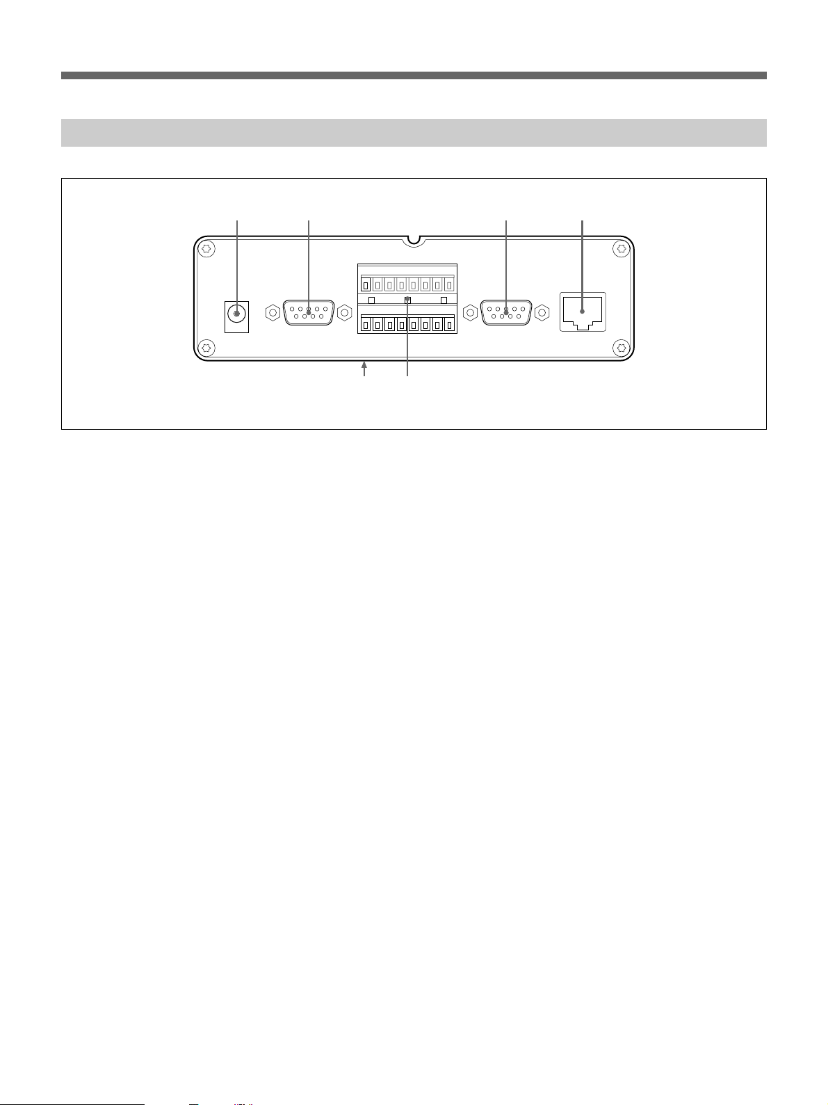
Rear Panel
1432
AC IN
(12V)
COM 1
~~
A3 C3 A4 C4 B A
12345678
+ – A1 C1 A2 C2 RELAY
67
COM 2
ETHERNET
10/100
1 AC IN (12 V) Input Terminal
The supplied AC adapter connects here.
2 COM 1 Terminal (9-Pin D-Sub)
The EVI-D30/D31/G20/G21 or HSR-1/1P/2/2P can be
connected to here. The EVI-D30/D31/G20/G21
connects using VISCA cable, and the HSR-1/1P/2/2P
connects with RS-232C cable.
3 COM 2 Terminal (9-Pin D-Sub)
The EVI-D30/D31/G20/G21 or a modem can be
connected to here. The EVI-D30/D31/G20/G21
connects using VISCA cable, and the modem connects
with RS-232C cable.
4 ETHERNET 10/100 Terminal (RJ-45)
Using Category 5 twisted-pair cable, connect this
terminal of the server to the network as a 10-Mbps
Ethernet or 100-Mbps Fast Ethernet device.
5 I/O Terminal Block Connector
This is an accessory input/output connector, used for
alarm inputs. Refer to “Basic Specifications” on page
41 for details.
6 MAC Address
The MAC address is shown on the label on the bottom.
6
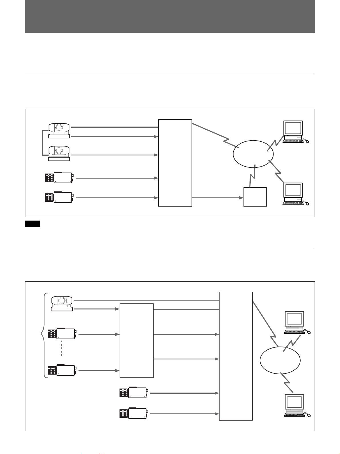
System Application Examples
•Up to four video sources can be connected to the server.
•Highest image quality can be distributed by using S-video.
Using the EVI-D30/D31
Connecting an EVI-D30/D31 to the video network station using the COM1 or COM2 terminal allows control of
pan, tilt and zoom from a computer on the network.
VISCA
Cable
EVI-D30/D31
EVI-D30/D31
Video Camera
Video Camera
VISCA Cable
S VIDEO
NTSC/PAL
NTSC/PAL
NTSC/PAL
COM1 Terminal
S-VIDEO Input Terminal
VIDEO 2 Input Terminal
SNT-V304
VIDEO 3 Input Terminal
VIDEO 4 Input Terminal
Ethernet 10/100 Terminal
COM2
Terminal
RS-232C
Cable
LAN or Internet
Modem
Note
Modem and Ethernet connections cannot both be used at the same time.
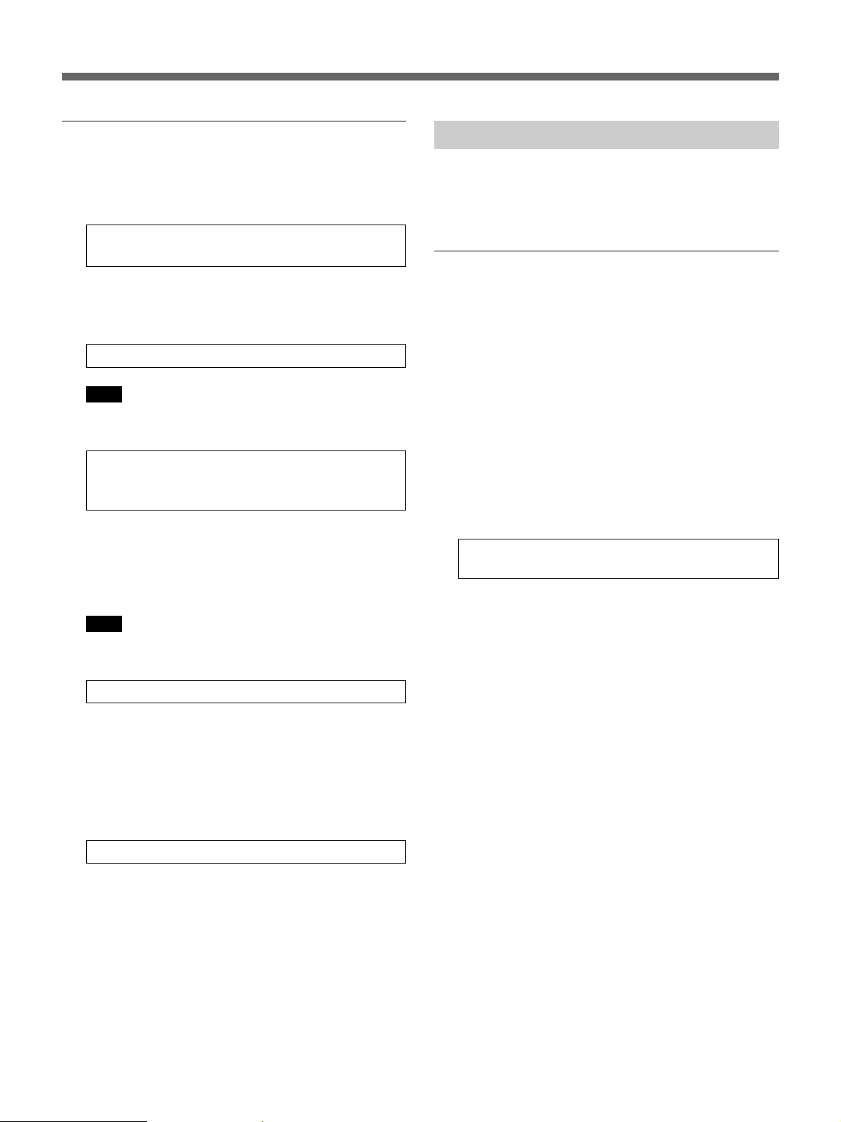
Using the HSR-1/1P/2/2P
By connecting an HSR-1/1P/2/2P to the COM1 terminal of the video network station, it can be set up and operated
by a computer on the network.
Up to
16
devices
EVI-D30/D31
Video Camera
Video Camera
VIDEO IN
NTSC/PAL
VIDEO IN
NTSC/PAL
VIDEO IN
NTSC/PAL
VISCA Cable
HSR-1/1P/
2/2P
Video Camera
Video Camera
RS-232C
VIDEO OUT
S VIDEO
VIDEO OUT B
Composite Video
NTSC/PAL
NTSC/PAL
COM2 Terminal
COM1 Terminal
S-VIDEO Input
Terminal
VIDEO 2 Input
Terminal
VIDEO 3 Input
Terminal
VIDEO 4 Input
Terminal
SNT-V304
Ethernet 10/100 Terminal
LAN or Internet
7

Installation
Installation
After connecting the video sources and the network to
the video network station, turn on the power switch
and set the IP address.
About the Operating Environment
The following operating environment is required to set
up the server and view the images.
•Computer: 400-MHz Pentium III with 64-MB RAM
or more
•Operating System: Windows 95/98, Windows NT 4.0
SP5 or later, or Windows 2000
•Web browser: Internet Explorer 5 (only)
Note
Before connecting an HSR-1/1P to the video network
station, verify that the HSR-1/1P software version is
2.01 or later. An HSR-1/1P with software version 1.xx
cannot be used with this device, so contact your Sony
Service Center for an upgrade, if needed.
Connections
Connect the video source, network and power to the
video network station as follows. Refer as needed to
the operating manuals of the devices to be connected.
IP Address Assignment
The video network station must be assigned an IP
address to allow access from computers on the
network.
Here we describe IP address assignment using the
ARP protocol.
z Hint
•ARP requires that an IP address be downloaded for
each new device.
•ARP cannot be used beyond the router.
•This device supports BOOTP.
Preparation
Before assigning the IP address, make the following
preparations.
•Obtain an unused IP address from your network
administrator
•Make a note of the MAC address shown on the label
on the bottom of the video network station.
•If the video network station is to be assigned a host
name, refer to your system manual or contact your
network administrator.
1 Turn off any devices to be connected.
2 Connect any devices required to the input and
output terminals of the video network station.
Note
The S VIDEO terminal and the VIDEO 1 terminal
cannot both be connected at the same time.
3 Connect the supplied AC adapter to a power outlet
and to the AC IN terminal of the video network
station.
Confirm that the POWER indicator lights steadily.
Note
Check with your network administrator before
assigning the IP address to the video network station.
8
Assigning the IP Address
Confirming Installation
1 Enter the following commands at an MS-DOS
prompt (or command prompt) on a computer on
the network:
arp -s <video network station IP
address> <MAC address>
z Hint
For example, your entries could be similar to the
following:
arp -s 192.36.253.80 08-00-46-08-14-da
Note
To use ARP with Windows 95, enter the
following:
arp -s <video network station IP
address> <MAC address> <Windows 95 host
IP address>
2 Disconnect the power cord to the video network
station briefly, then reconnect it and enter the
following at the MS-DOS prompt (or command
prompt) from a computer on the network.
Note
This command should be executed within two
minutes after reconnecting the power cord.
ping <video network station IP address>
The video network station reboots and a “Request
time out” message is returned.
3 Enter the following at the MS-DOS prompt (or
command prompt) from a computer on the
network.
ping <video network station IP address>
To confirm the connection, access the video network
station using a Web browser on a computer on the
network.
Web Browser Preparation
Internet Explorer 5 must be installed on a computer to
set up the video network station and to view images.
The “Sony ActiveX Camera Control” (ActiveX
component) is installed by the following procedure.
1 Launch Internet Explorer.
2 In the [Tools] menu, select [Internet Options],
click the [Security] tab, set the [Security level of
this zone] to “Low”, and click [OK].
3 Enter the following in the [Address] box, and press
the Enter key.
http://<host name or IP address of the
video network station>/
A message appears asking to “Install and execute
“http://<video network station IP address>/activex/
ATLCamImage.ocx” ”.
z Hint
If a message appears requesting that you download
and install the Microsoft Virtual Machine, this
component was not installed when Internet
Explorer was installed. In this case, download and
install the Microsoft Virtual Machine according to
the screen instructions.
4 Select “Yes” to install the “SONY ActiveX
Camera Control” according to the screen
instructions.
When the video network station IP address has
been entered and communications established, the
“Reply from ...” message appears.
5 When installation is finished, again select [Internet
Options] in the [Tools] menu, click the [Security]
tab, return the [Security level of this zone] to its
original setting, and click [OK].
9
Installation
Accessing the Video Network Station
1 Run the Web browser.
2 Enter the following in the [Address] box, and press
the Enter key:
http://<host name or IP address of the
video network station>/
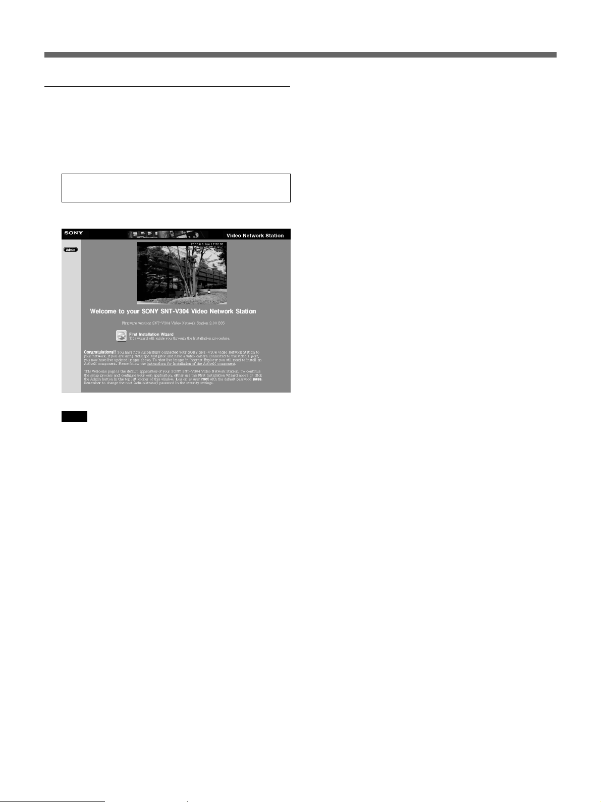
The “Welcome” page appears.
Note
Response may be slow depending on the condition
of the network. If screen display is delayed, stop
the URL loading, and try accessing again.
z Hints
•If the “Layout and Application Wizard” (page 13)
has been used to make settings when the server
was accessed in the past, a monitor screen
appears instead of the “Welcome” page.
•The image of the video camera connected to the
VIDEO 1 terminal is displayed on the
“Welcome” page. If no video camera is
connected to this terminal, “NO VIDEO” appears
instead.
•Data is stored in the cache so that it can be
quickly displayed by the Web browser. If the
server has been accessed before, data saved in the
cache may be displayed, in which case pressing
the [Refresh] button in the browser will cause the
latest data to appear.
10
Settings
This chapter describes how to set up the video network
station for various system types and applications.
Video network station settings are made using Internet
Explorer 5.
Note
If the computer used for making video network station
settings or viewing the monitor screen is shared with
other users, we recommend closing the Web browser
when finished operations. Until the browser has been
closed, even after moving to another Web page, the
password-protected video network station’s Web page
remains accessible, for example, by clicking the
[Back] button.
z Hints
•The IP address must be assigned according to the “IP
Address Assignment” procedure on page 8 before
setting the video network station.
•Items that can be set are listed in the “Settings List”
on page 44.
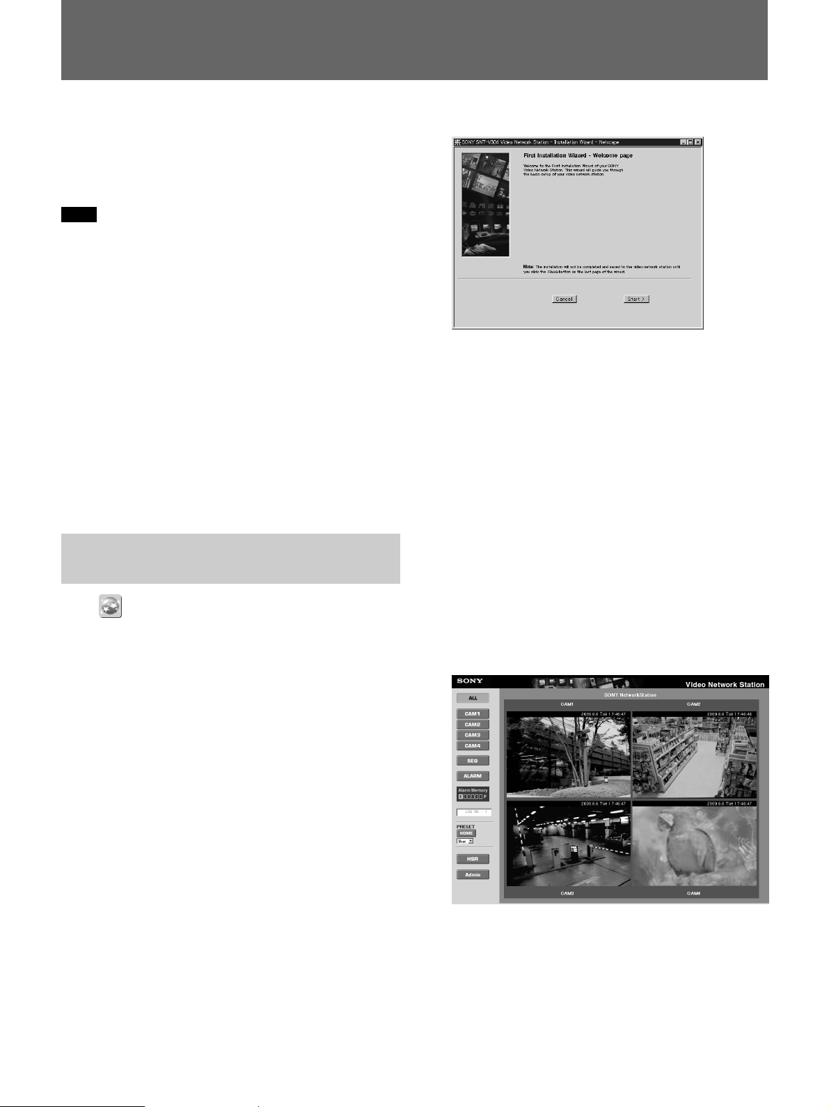
Basic Settings with the First Time Installation Wizard
Click (First Time Installation Wizard) to make the
basic video network station settings with interactive
instructions.
The “First Time Installation Wizard” icon appears on
the “Welcome” page.
The Wizard appears.
2 Follow the Wizard’s on-screen instructions to
make the settings.
z Hint
For details of particular settings, refer to the
corresponding page in the Settings List information
beginning on page 44.
3 Click the [Finish] button when you reach the end
of the Wizard.
A server reboot confirmation message appears.
4 Click [OK].
The settings are saved.
5 Click the Browser’s [Refresh] button.
The monitor screen appears with the new settings
applied.
z Hints
•Settings can be made without the Wizard. In this
case, click the [Admin] button on the “Welcome”
page, and refer to “Accessing the Administration
Overview Page” on page 12.
•If the “Layout and Application Wizard” (page 13) has
been used to make settings when the server was
accessed in the past, the “Welcome” page does not
appear. In this case, click the Admin button on the
“Welcome” page, and refer to “Accessing the
Administration Overview Page” on pege 12.
•The “First Time Installation Wizard” can be accessed
from the Administration Overview page.
1 Click the “First Time Installation Wizard” icon on
the “Welcome” page, and click [OK] when the
confirmation message appears.
To change settings in the future, or to set
parameters not available in the Wizard, refer to the
following “Accessing the Administration
Overview Page” section.
11

Installation
Accessing the Administration Overview Page
Click the (Admin) button to display the
“Administration overview” page. After basic settings
have been made with the “First Time Installation
Wizard”, all video network station settings and
management are performed from the “Administration
overview” page.
1 Launch the Web browser and enter the following
in the [Address] box, and press Enter.
http://<host name or IP address of the
video network station>/
The monitor screen appears.
2 Click the [Admin] button.
The “Enter User Name and Password” dialog box
appears.
3 Enter “root” as the system user name, and the
password that was set previously, and click [OK].
The “Administration overview” page appears.
Note
•The factory-default administrator (root) password
is “pass”. Unless the administrator’s password
has been changed, enter “pass” for the password.
However, as all units are programmed with the
same settings at shipping time, you should change
the password as soon as possible. Refer to
“Changing Passwords and User Registration” on
page 16 for the procedure.
•A message such as There is no Data may appear
when changing the window size from the
“Administration overview” page. In this case,
click the right mouse button, and select [Refresh].
1
2
1 Menu
(Admin Overview): Click to return to the
initial “Administration overview” page.
(View Application): Click to open a monitor
screen window. Changes to settings related to the
monitor mode can be confirmed in this window.
2 Items
The system’s structural elements are indicated by the
icons. Clicking on an item displays related settings that
can be changed in the Settings area at the right.
3
3 Settings Area
Text boxes and icons are displayed for setting the
selected item.
The “First Time Installation Wizard” icon is displayed
on the initial screen. Refer to “Basic Settings with the
First Time Installation Wizard” on page 11 for details.
12
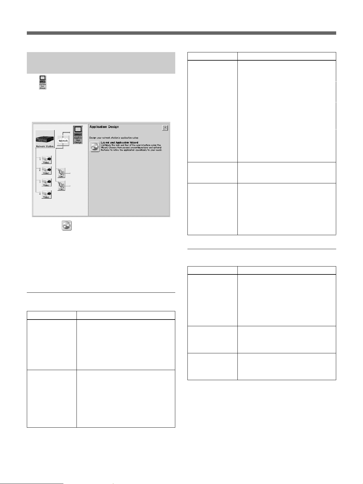
Monitor Screen and Alarm Function Setup
The (Application Design) icon is used to configure
the monitor screen display and to determine the
operation of the video network station when an alarm
event occurs. Clicking the “Application Design” icon
displays the following screen.
Clicking the (Layout and Application Wizard)
icon displays the “Layout and Application Wizard”.
When the wizard is first run, a screen appears on
which to select either [Layout] or [Application]
settings. Select [Layout] to configure the monitor
screen, or select [Application] to set alarm inputs and
alarm event responses.
Layout Settings
Setting
Which view do you
want to display as
default when
opening the Web
interface?
What type of
image do you want
to show in Web
pages?
Description
Select which image is to be initially
displayed when the user accesses the
monitor screen:
• Camera View
Displays the video camera image
• HSR View
Displays the HSR-1/1P/2/2P image
Select the image size for the monitor
screen from the following:
• Fullsize
Display 352 × 240 NTSC or 352 ×
288 PAL
• Hugesize
Display 704 × 480 NTSC or 704 ×
576 PAL
Setting
What format do
you want ALL in
camera view to be
in?
Woud you like to
display the Sony
logo?
Please enter the
time for sequential
switching:
Description
Select the images and layout to be
displayed on the monitor in the ALL
mode from the following:
• All cameras
All video camera images are
displayed.
• Camera 1 and 2 horisontally aligned
Images of the video cameras
connected to VIDEO 1 and 2
terminals are displayed side by side.
• Camera 1 and 2 vertically aligned
Images of the video cameras
connected to VIDEO 1 and 2
terminals are displayed one above
the other.
Select whether to display the Sony
logo at the top of the page: either [Yes]
(display) or [No] (no logo).
Enter an image display interval for
each of the four video sources. Setting
0 for a video source causes it to not be
displayed on sequential mode. Also, if
a short interval is set, the image may
not be displayed, depending on
network conditions and processing
speed of the computer.
Application Settings
Setting
Alarm Buffer,
Overwrite
Alarm Pop-Up
Window
Switch image
when Alarm is ON
Description
A pre-determined amount of memory
is used to store images before and
after an alarm event. If the quantity of
images exceeds the allotted amount,
select whether to overwrite previously
stored contents, oldest first. Select
either [ON] (overwrite) or [OFF] (no
overwrite).
Select whether a pop-up window
should appear when an alarm event
occurs: either [Enable] (display popup) or [Disable] (no pop-up).
Select whether to switch the display to
the alarm-detecting camera when an
alarm event occurs: either [Enable] or
[Disable] switching.
13
Installation
Dialog boxes relating to [Input 1] (Alarm Input 1) to
[Input 4] (Alarm Input 4) are displayed for the
following items.
Setting
Alarm Enabled
Always
Restricted
Between
Start
Stop
Mon to Sun
Alarm ON at:
Positive-edge
Alarm ON at:
Negative-edge
Image every X
second(s)
Number of PRE
alarm images
Number of POST
alarm images
Alarm duration
No Upload
Upload Via FTP
Host Name
User Name
Password
Upload Via e-mail
(one image only)
To Email
Subject
Text
Camera Link
Description
Alarm input is enabled when this box is
checked.
Alarm input is always enabled when
this radio button is selected.
Alarm input is enabled for a specific
time of day when this radio button is
selected.
When the [Restricted Between] radio
button is selected, enter the start time
here.
When the [Restricted Between] radio
button is selected, enter the stop time
here.
Check the boxes to specify particular
days on which the alarm input should
be enabled.
Check this box to have a rising alarm
input signal indicate the occurrence of
an alarm event.
Check this box to have a falling alarm
input signal indicate the occurrence of
an alarm event.
Select the storage interval for images
during an alarm event.
Enter the number of images (0 to 10)
to be saved prior to an alarm event.
Enter the number of images (0 to 50)
to be saved after an alarm event.
Enter the time (seconds) from an
alarm occurrence until the alarm mode
is cleared.
Select this radio button to disable
transfer of saved images.
Select this radio button to transfer
saved images by ftp.
Enter the host name of the transfer
destination.
Enter the user’s name on the host at
the transfer destination.
Enter the password of the above user.
Select this button to send a saved
image as an e-mail attachment.
Enter the mail address of the
destination for image files. Multiple
addresses may be entered by
separating with commas. Up to 100
characters may be entered.
Enter the title text for the e-mail.
Enter the body text for the e-mail.
Check this box to include in the e-mail
a link to the real-time image on the
camera where an alarm event occurs.
Setting
Upload Path: (FTP
only)
Base File Name
Date/Time Suffix
Sequence
Number
Suffix set to
Maximum
Sequence
Number
Suffix up to:
Note
Description
Enter the path of the save destination
for image files sent by ftp to a host.
Enter the base file name for image
files to be sent.
Select this radio button to have the
date and time appended to the base
file name.
Select this radio button to have a
sequential number appended to the
base file name.
When a sequential number is attached
to the base file name, to set an upper
limit to the numbering, select this radio
button and enter the upper limit.
•Alarm events that occur while writing to alarm
memory are not saved in the memory.
•When an alarm event occurs immediately after
writing to the alarm memory, the image stored may
not comply with the settings applied to images prior
to the alarm.
•When an alarm event occurs while the pop-up
window is displayed, the time set for the [Alarm
duration] is extended. A second pop-up window will
not appear.
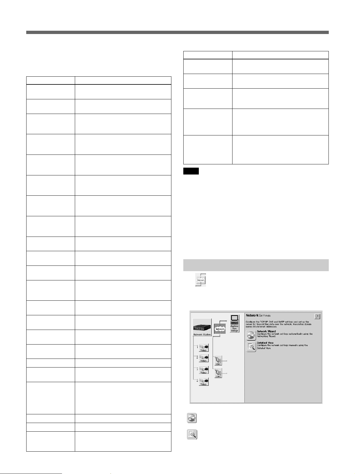
Network Settings
The (Network Settings) icon is used for settings
related to the supporting network protocol. Clicking
the “Network Setting”s icon displays the following
screen.
Settings can be made with the following procedures.
•
(Network Wizard) icon: click to display Wizard
instructions for making the settings.
•
(Detailed View) icon: click to display a dialog
box with [TCP/IP], [DNS] and [SMTP EMail] tabs
that you can select to make corresponding settings.
14
Settable contents are shown in the following table.
Setting Description
TCP/
IP
DNS
SMTP
BOOTP*
Internet
Address
Default
Router
Subnet
Mask
Host Name
Bandwidth
Control
Domain
Name
Primary
DNS Server
Secondary
DNS Server
Primary
Mail Server
Secondary
Mail Server
Return
Email
Address
Enable the BOOTP protocol to
automatically download the IP
address.
Enter the video network station IP
address.
Enter the network default router
address.
Enter the network subnet mask. This
parameter is used to determine
whether communication is passed
through the router.
Enter the video network station’s host
name.
Network bandwidth to be assigned to
the video network station is selected
from the drop-down list.
Enter the network domain name.
Enter the IP address of the primary
DNS server. The DNS server is used
to recognize computers by domain
names instead of IP addresses.
Enter the IP address of the secondary
DNS server. The secondary DNS
server is used when the primary DNS
server is unusable or unavailable.
Enter the IP address or name of the
primary mail server.
Enter the IP address or name of the
secondary mail server. The secondary
mail server is used when the primary
mail server is unusable or unavailable.
Enter the return address of email sent
from the video network station, which
is the mail address you wish to appear
in the “FROM” field of email send from
the video network station.
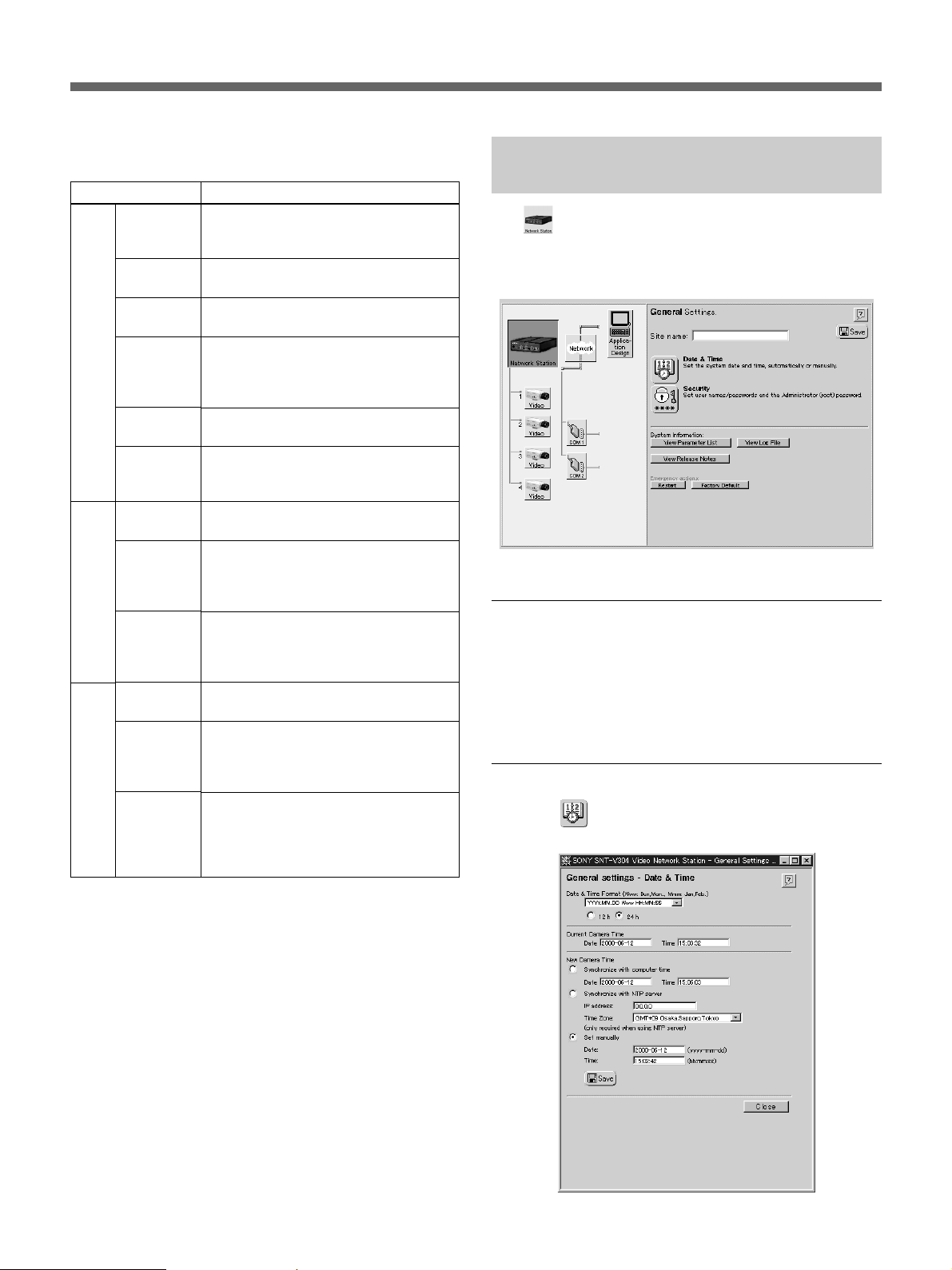
System Administration and Security
The (Network Station) icon is used to configure
the security of the video network station or system
administrator. Clicking “Network Station” displays the
following screen.
Setting a Site Name
Enter the site name in the [Site name] text box that you
wish to have displayed at the top of the monitor screen,
and click the “Save” icon to save the new name. The
site name may consist of up to 40 characters.
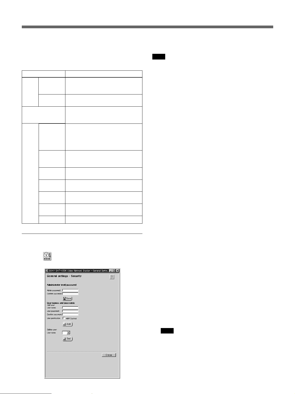
Set Date and Time
Click the (Date & Time) icon to display the
“General settings – Date & Time” dialog box.
*This setting cannot be changed with the “Network
Wizard”.
15
Installation
The setting items are shown in the following table.
When finished setting, click the “Save” Icon. The
accuracy of the internal clock is ±120 seconds/month
or less.
Setting
Date &
Time
Format
12h/24h
Current Camera
Time
New
Camera
Time
Synchronize
with
computer
time
Synchronize
with NTP
server
IP address
Time Zone
Set
manually
Date
Time
Description
Select the display format for date and
time on the monitor screen from the
drop-down list.
Select either [12h] or [24h] for 12- or
24-hour time display.
Displays the current date and time.
The displayed date and time cannot
be edited.
Turn this on to synchronize the video
network station clock with the
computer’s internal clock. The
displayed date and time cannot be
edited.
Turn this on to synchronize the video
network station clock with an NTP
server.
Enter the IP address of the NTP
server.
Select your time zone from the dropdown list.
Enable this if you need to set the
date and time manually.
Enter the date (yyyy-mm-dd), from
1970-01-01 to 2031-12-31.
Enter the time (hh:mm:ss)
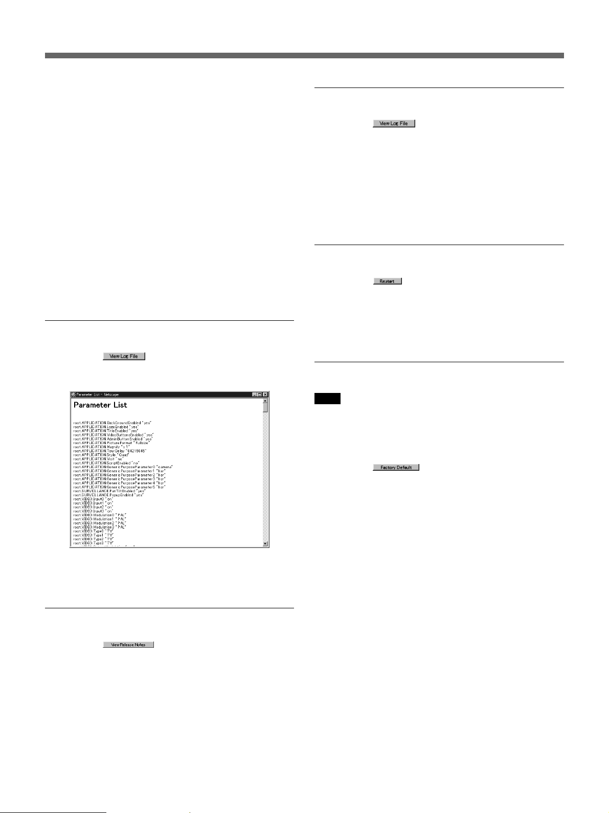
Changing Passwords and User
Registration
Changing the System Administrator Password
Note
When the video network station is shipped from the
factory, the system administrator’s user name and
password are set to “root” and “pass”. As all units are
programmed with the same settings at shipping time,
you should change the password as soon as possible.
Enter the new administrator’s password in the [Admin
password] field and again in the [Confirm password]
field, then click the “Save” icon. A valid password
consists of up to eight characters, consisting of a-z, AZ and 0-9.
Registering a User
With the default setup as shipped from the factory, any
user on the network can access the video network
station. There is no need to register users if access is to
be permitted to anonymous users. However, if access
is to be limited to specific users, register the users by
the following procedure. If more than one user is
registered, video network station connections are
password protected.
1 Enter a user name to be registered in the [User
name] field of the [Add user] item, and enter their
password in the [User password] and [Confirm
password] fields. A user name may be up to ten
characters long, and a password up to eight
characters long, both consisting of a-z, A-Z and
0-9.
Click the (Security) icon to display the “General
settings – Security” dialog box.
16
2 Place a check in the [HSR Control] checkbox if the
user has permission to control the HSR-1/1P and
HSR-2/2P.
z Hint
The [CTR] button appears in the HSR view to
users for whom this box is checked. Clicking the
[CTR] button accesses the “HSR CONTROL”
page. Refer to “HSR View Mode” on page 33 for
information about controls for HSR View and the
HSR-1/1P/2/2P.
Note
HSR-1/1P/2/2P password-protected functions such
as Key Lock on/off are accessible from the “HSR
CONTROL” page. Access permission to the “HSR
CONTROL” page should be considered very
carefully.
3 Click the “Add” icon.
4 Repeat the above steps to add more users.
Up to 20 users can be registered.
Displaying the Log File
5 Click the [Close] button to close the dialog box.
Unregistering a User
1 Select the name of the user to be unregistered from
the [User name] drop-down list in the [Delete user]
area, and click the “Del” icon.
The registration of the selected user is deleted.
2 To delete another user registration, repeat step 1.
3 Click the [Close] button to close the dialog box.
Displaying the Parameter List
Clicking the (View Parameter List) button
opens a new window to display the “Parameter
Settings List” page.
Clicking the (View Log File) button opens a
new window to display the “Log file Events” page.
Recently executed commands are displayed on the
“Log file Events” page. The log file is used to check
whether a special event was executed, such as whether
a command was issued before or after an alarm
occurred. The log also serves as a diagnostic tool to
resolve operational problems.
Restarting the Video network station
Clicking the (Restart) button displays a
confirmation message for you to restart the video
network station. If you click [OK], the “General
Settings” page will be redisplayed after the server
restarts.
Reverting to Factory Default Settings
Note
This operation returns all settings, including the video
network station IP address, to their factory-default
values.
All settings except passwords can be viewed in this
list.
Displaying Release Notes
Clicking the (View Release Notes) button
opens a new window to display the “Release Notes”
page.
The “Release Notes” page shows the video network
station firmware and software version information.
Clicking the
displays a confirmation message. If you click [OK], all
settings in the video network station are returned to
their original shipped state.
(Factory Default) button
17
Installation
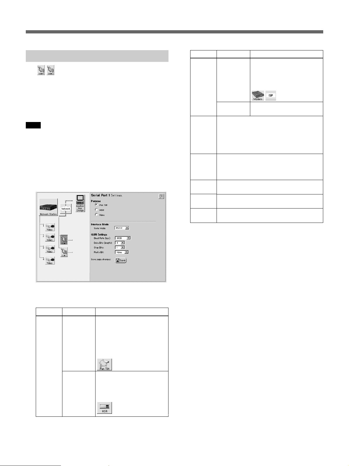
Serial Port Settings
The (COM1 and COM2) icons represent the
serial ports of the video network station. Use these
icons when an EVI-D30/D31/G20/G21 or HSR-1/1P/
2/2P is connected to the “COM1” or “COM2” ports to
set up serial port function and communications
parameters.
Note
If a serial port has the Click “Save” icon enabled, the
video network station reboots and alarm memory
contents are erased, so check the alarm memory
contents, if necessary, before setting.
1 Click the “COM1” (or “COM2”) icon.
The screen displays the “Serial Port 1 Settings” (or
“Serial Port 2 Settings”).
Setting
Purpose
Serial
Mode
(only
displayed
for
COM1)
Baud
Rate
(bps)
Data Bits
(length)
Stop Bits
Parity Bit
Options
Modem
(only
displayed for
COM2)
None
Select the appropriate interface type:
[RS232] for the EVI-D30/D31/G20/G21 and
HSR-1/1P/2/2P.
Select the transfer speed: Select [9600] for
the EVI-D30/D31/G20/G21, or [9600] to
[38400] as the HSR setting to match that of
the HSR-1/1P/2/2P.
Select [8] data bits for the EVI-D30/D31/
G20/G21 and HSR-1/1P/2/2P.
Select [1] stop bit for the EVI-D30/D31/G20/
G21 and HSR-1/1P/2/2P.
Select [None] for the EVI-D30/D31/G20/
G21 and HSR-1/1P/2/2P.
Description
Select this if a modem is
connected to the port.
When selected, the “Modem”
and “ISP” icons shown below
are displayed.
Select this if no device is
connected to a port.
2 Make the required settings. Available settings are
as follows.
Setting
Purpose
Options
Pan Tilt
HSR (only
displayed for
COM1)
Description
Select this if an EVI-D30/
D31/G20/G21 is connected to
the port.
When selected, the “Pan Tilt”
icon shown below is added
next to the “COM1” or
“COM2” icon.
Select this if an HSR-1/1P/2/
2P is connected to the port.
When selected, the “HSR”
icon shown below is added
next to the “COM1” icon.
3 Click the “Save” icon when finished with the
settings.
The new settings are saved, the video network
station reboots, and the display changes as follows
depending on the selected usage.
•When [Pan Tilt] is selected, the “Pan Tilt
Settings” page appears. Refer to “Pan/Tilt Driver
and Video Camera ID Setup” below.
•When [HSR] is selected, the “Sony HSR
Settings” page appears. Refer to “HSR-1/1P/2/2P
Setup” on page 20.
•When “Modem” is selected, the “Modem
Settings” page appears. Refer to “Modem Setup”
on page 22. Also, to set up dial-up connection via
modem, refer to “ISP (Internet Service Provider)
Setup” on page 22.
18
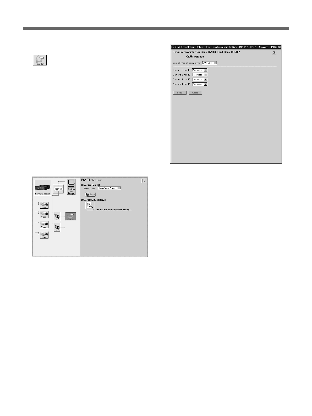
Pan/Tilt Driver and Video Camera ID Setup
The (Pan Tilt) icon is displayed when a Pan/Tilt
device is selected for the serial port usage. If the “Pan
Tilt” icon is not displayed next to the icon of the
applicable serial port, refer to “Serial Port Settings” on
page 18 to reset the serial port usage.
Up to seven VISCA-compliant video cameras can be
connected by daisy chaining to the two serial ports on
the video network station, with pan/tilt/zoom
controlled by the ID number of each video camera.
The “Pan Tilt” icon is used to set the driver, video
camera ID number and video camera preset position
for each connected device.
The following example describes connection of an
EVI-D30/D31/G20/G21.
1 Click the “Pan Tilt” icon in the Items area.
The “Pan Tilt Settings” screen appears.
4 Select the connected video camera from the [Select
type of Sony driver] drop-down list.
5 Select an ID number in one of the [Camera 1] to
[Camera 4] drop-down lists.
2 Verify that [Sony Visca Driver] is selected in the
[Select Driver] drop-down list.
3 Click the Driver Specific Settings icon to change
the ID number of the video camera.
The “Specific parameters for Sony G20/G21 and
Sony D30/D31” page appears.
z Hint
•The ID number must be unique from other
devices.
•Set the number according to the daisy-chain
connection sequence.
•When an HSR-1/1P/2/2P is connected to the
COM1 terminal, an ID number can be set for
each camera connected to the HSR-1/1P/2/2P.
6 Click the [Apply] button.
Settings are applied, and a “Preset Positions” icon
is added to the video camera for which the ID
number was set.
7 If setting video camera preset positions, go to
“Setting Pan/Tilt Camera Preset Position” below.
Otherwise, click the [Close] button to finish with
settings.
19
Installation
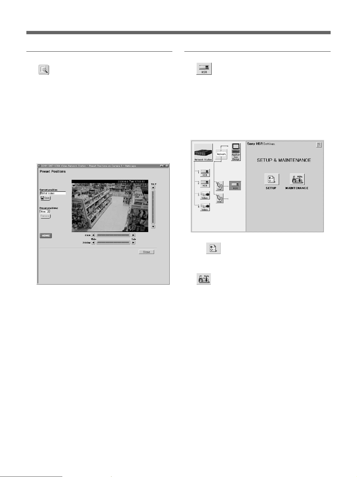
Setting Pan/Tilt Camera Preset Position
The (Preset Positions) icon is used to set preset
positions for a pan/tilt camera.
The administrator can set and name up to 20 preset
positions for a video camera. Users can then position
the video camera quickly and accurately by merely
recalling a preset position.
1 Click the “Preset Positions” icon on the “Specific
parameter for Sony G20/G21 and Sony D30/D31”
page.
The “Preset Positions” page appears in a new
window.
HSR-1/1P/2/2P Setup
The (HSR) icon is displayed when HSR-1/1P/2/
2P is selected for the serial port usage. When an HSR1/1P/2/2P is connected to the video network station’s
COM1 terminal, if the “HSR” icon does not appear
next to the “COM1” icon, reset the serial port usage by
referring to “Serial Port Settings” on page 18.
Click the “HSR” icon to display the “Sony HSR
Settings” page.
2 Observe the sample video camera image while
adjusting the camera position using the [Pan],
[Tilt] and [Zoom] control bars. Refer to “Pan/Tilt/
Zoom Control” on page 28 for details.
3 Enter a name (up to 16 characters) for the preset
position in the [Current position] text box.
4 Click the “Save” icon.
The name of the preset position is added to the
[Preset positions] drop-down list.
5 To delete an existing preset position, select the
name of the position in the [Preset positions] dropdown list, and click the [Remove] button.
6 Click the [Close] button when finished with the
settings.
The “Preset Positions” page closes.
Use the (SETUP) icon to make HSR-1/1P/2/2P
settings from the Web page. Clicking the “Setup” icon
displays the “SETUP MENU”.
The
information for servicing an HSR-1/1P/2/2P unit.
Clicking the “MAINTENANCE” icon displays the
“MAINTENANCE MENU”. Refer to the HSR-1/1P/2/
2P Users Guide for details of HSR-1/1P/2/2P settings.
Before making any settings, see the following “HSR-1/
1P/2/2P Setting Precautions”.
HSR-1/1P/2/2P Setting Precautions
•Always click the [SET] button after making a
setting.
To apply changed settings, the [SET] button must be
clicked on each page. Changes to settings will not be
saved unless you click the [SET] button.
•Display response may slow briefly while settings
are being saved.
Some display slow-down is normal while settings are
being stored in the HSR-1/1P/2/2P: this does not
indicate a problem with the video network station.
(MAINTENANCE) icon is used to display
20

•Available settings differ according to the type of
HSR connected.
Some settings are different for the HSR-1/1P and
HSR-2/2P, which are automatically detected by the
video network station.
•Recording Mode Setting Procedure
To set the recording mode, open the “RECORDING
MODE 1” - “RECORDING MODE 5” pages from
the “RECORDING FUNCTION” page, and set the
following items:
– [CAMERAS]
– [TAPE LENGTH]
– [IMAGE QUALITY]
– Either [TIME MODE] or “RECORDING
CYCLE”
The HSR-1/1P/2/2P automatically calculates the
value of either [TIME MODE] or “RECORDING
CYCLE” that was not entered when you click the
“SET” button. If the entered value is outside of the
valid setting range, an error message appears, so you
can enter a valid value. To verify the settings, display
the “RECORDING MODE 1” through
“RECORDING MODE 5” pages again.
•Relationship between HSR-1/1P/2/2P Passwords
and Video Network Station Password
The password entered for “PASSWORD SETTING”
on the “FUNCTION CONTROL” page restricts
operation of the HSR-1/1P/2/2P (which is different
from the “Security” password set for the video
network station – see page 16). However, the system
manager (root user) of the video network station can
change the passwords for any connected HSR-1/1P/2/
2P. The system manager’s password should therefore
be handled carefully.
•Time Display Format
The following four display formats are available on
the HSR-1/1P/2/2P “INDICATION CONTROL”
page, which are independent of the video network
server’s “Date & Time” (see page 15).
– “SETUP MENU” - “TIME ADJUSTMENT”
– “SETUP MENU” - “RECORDING FUNCTION”
- [TIMER RECORDING]
– HSR View - “HSR CONTROL” - [TIME
SEARCH]
– HSR View - “HSR CONTROL” - [ALARM
SEARCH] - [ALARM LIST]
To change these display formats, change the [DATE
FORMAT] and [TIME FORMAT] on the
“INDICATION CONTROL” page.
•Setting the HSR-1/1P/2/2P Communications Speed
to Match the Video Network Station
When changing the [RS-232C] communications
speed on the “REMOTE CONTROL” page, be sure
to also set the video network station communications
speed on the “Serial Port 1 Settings” page (see page
18) to the same value. If these settings are not the
same, the video network station will be unable to
control the HSR-1/1P/2/2P.
•The “SERVICE USE” Page is for Maintenance
Service
The “SERVICE USE” page in the
“MAINTENANCE MENU” is for maintenance
service. It is password protected to prevent display to
users.
•Setting and Canceling HSR-1/1P/2/2P Passwords
The password entered for “PASSWORD SETTING”
on the “FUNCTION CONTROL” page may consist
of up to four characters. Asterisks (*) are displayed
when the HSR-1/1P/2/2P password has been set. To
cancel a password, delete the displayed asterisks (*)
and click the Set button with both [USER
PASSWORD] and [CONFIRM PASSWORD] boxes
empty.
21
Installation
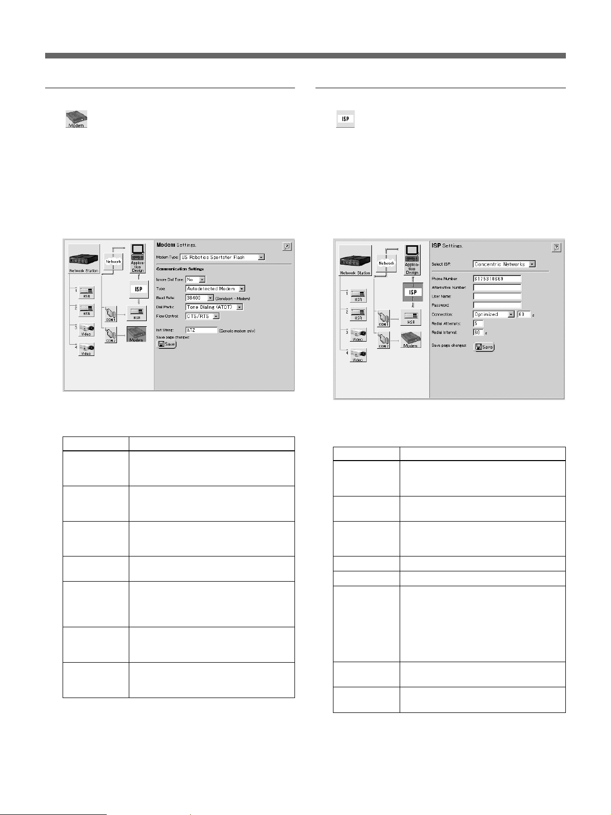
Modem Setup
The (Modem) icon is displayed when [Modem] is
selected for the serial port usage. When a modem is
connected to the video network station, if the
“Modem” icon does not appear next the “COM2” icon,
refer to “Serial Port Settings” on page 18 to reset the
serial port usage.
1 Click the “Modem” icon.
The “Modem Settings” page appears.
ISP (Internet Service Provider) Setup
The (ISP) icon is displayed when [Modem] is
selected for the serial port usage. The “ISP” icon is
used to set up connection with an “ISP” (Internet
Service Provider). If the “ISP” icon is not displayed,
reset the serial port usage according to “Serial Port
Settings” on page 18.
1 Click the “ISP” icon.
The “ISP Settings” page appears.
2 Set the necessary items. Settable items are shown
in the table below.
Setting
Modem Type
Ignore Dial
Tone
Type
Baud Rate
Dial Prefix
Flow Control
Init String
Description
Select the connected modem. If a
matching modem type cannot be
found, select [Generic].
Select [NO] to start connecting after
detecting a dial tone, or select [YES] to
start connecting without a dial tone.
Select [Null] if the modem is connected
with a null-modem (crossed) cable, or
[Autodetected Modem] otherwise.
Select the communication speed
between the serial port and modem.
Select either [Tone Dialing (ATDT)] or
[Pulse Dialing (ATDP)] according to
the type of telephone circuit used for
the modem connection.
Select [CTS/RTS] if flow control is
available, or [OFF] to disable flow
control.
If [Modem Type] is set to [Generic
Modem], enter the required modem
initialization string.
3 Click the “Save” icon to save your settings when
finished.
2 Set the necessary items. Settable items are shown
in the table below.
Setting
Select ISP
Phone
Number
Alternative
Number
User Name
Password
Connection
Redial
Attempts
Redial Interval
Description
Select the destination ISP. If a
matching ISP cannot be found, select
[Generic].
Enter the telephone number of the
connection destination.
Enter the alternate telephone number
to be used if connection cannot be
established with the above number.
Enter the user name for ISP host login.
Enter the password.
Select [Always Open] to allow
unlimited connection to the ISP. Select
[Close after] to limit the connection
time, and enter the time limit (in
seconds). To have the ISP connection
cut automatically after transferring
images, select [Optimized].
Enter the number of times to attempt
redialing when a connect attempt fails.
Enter the interval (in seconds)
between redial attempts.
3 Click the “Save” icon to save your settings when
finished.
22
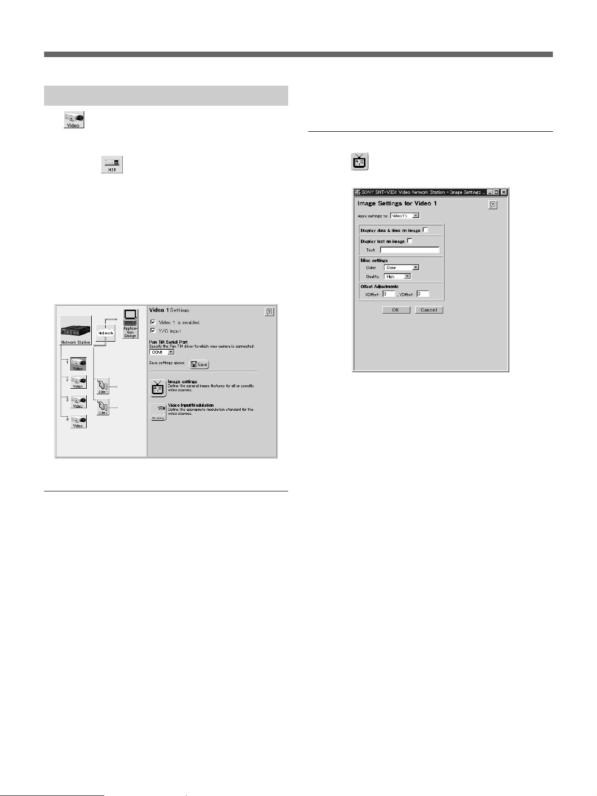
Video Input Setup
The (Video) icons indicate the video sources
connected to the VIDEO 1 to VIDEO 4 input
terminals. If the serial port usage is set for an HSR-1/
1P/2/2P, the
and [2] video input terminals.
An “×” appears to the left of an icon if no video signal
is present at the corresponding input terminal.
This example describes the video input setup
procedure for an EVI-D30/D31/G20/G21 connected to
the S VIDEO input terminal. Set up the other input
terminals similarly.
Clicking the “Video” icon of video input [1] displays
the following screen.
(HSR) icon is displayed at the [1]
3 Click the “Save” icon.
The settings are saved.
Video Image Settings
Click the (Image settings) icon to display the
“Image Settings for Video 1” dialog box.
Enabling and Disabling Video Inputs
1 Confirm the [Video 1 is enabled.] box is checked.
z Hint
•For optimum performance, we recommend
clearing the checkboxes for any input terminals
that are not being used.
•When unchecked, the input terminal is displayed
as [Disabled].
2 Check the [Y/C input is disabled.] checkbox.
z Hint
•When the EVI-D30/D31/G20/G21 is connected to
the VIDEO 1 input terminal, this setting is off
(unchecked).
•This setting is not available for video inputs [2] to
[4].
If only the current video source is to be set, select
[Video 1’s] in the [Apply settings to] drop-down list.
Otherwise, if all video sources are to be set together,
select [All Videos’]. Click [OK] to save the settings.
23
Installation
Items that can be set are as follows:
Setting
Display date & time
on image
Display text
on image
Text
Misc settings Color
Quality
Offset Adjustments
Description
Check this box to display the date
and time with the video image.
Check this box to display text such
as the camera title with the video
image.
Enter the text to display to be
displayed (up to 16 characters).
Select whether the video image is to
be displayed as color or
monochrome.
Select one of the five video image
compression ratios. The highest
image quality is [Hyper], but this
requires the largest image file size
and network bandwidth.
Enter the horizontal display position
of an image as the [X Offset], and
the vertical position as the [Y Offset].
The usable range for [X Offset] is –4
to +4 (pixels), and for [Y Offset], –2
to +2 (pixels). The [Y Offset] setting
is valid only when the image display
is [Fullsize]. Verify the monitor
screen after changing settings, and
correct the setting values if the
image does not display correctly.
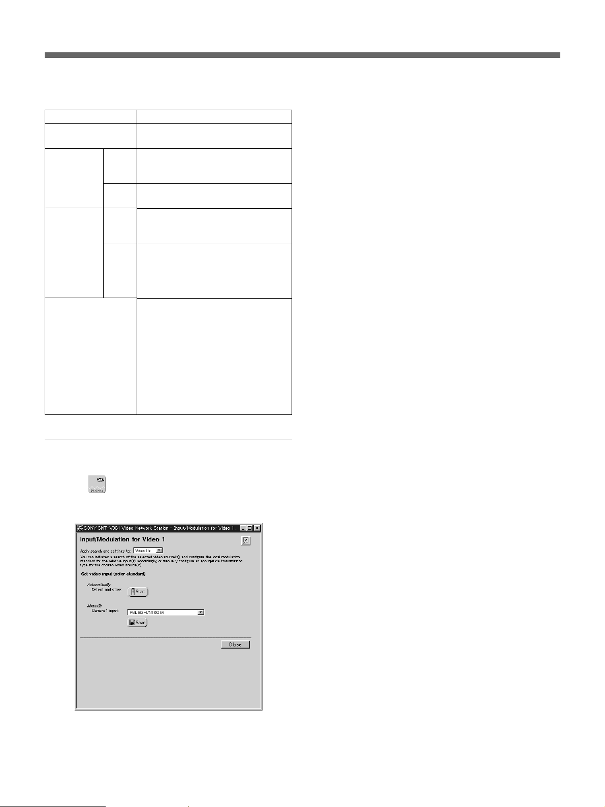
Setting the Video Input Modulation
Method
If only the current video source is to be set, select
[Video 1’s] in the [Apply detection and settings to]
drop-down list. Otherwise, if all video sources are to
be set together, select [All Videos’]. Then select the
modulation method for the video input: either by
manual setting or automatic detection.
Automatic Setting
Clicking the [Start] button initiates testing of the video
source to detect the modulation type to be assigned to
the selected source.
Manual Setting
Select a modulation type from the [Camera 1 input]
drop-down list, and click the “Save” icon to save the
selection.
z Hint
Several different video modulation standards are
currently used in different regions. The NTSC video
format, generally used in Japan and North America,
consists of images composed of 525 lines of resolution
displayed at 60 fields per second. The PAL (Phase
Alternating Line) video format, which is the common
European television standard, consists of images
composed of 625 lines displayed at 50 fields per
second. The video network station supports NTSC,
PAL and several other standards derived from them.
Click the (Video Input/Modulation) icon to
display the “Input/Modulation for Video 1” dialog
box.
24
Operation
This chapter describes how to monitor the images
distributed from the server.
z Hint
•The functions of the video network station and the
views and operation of the monitor screen are set by
the system administrator according to the
requirements of the surveillance system. So the
functions and screens shown in this chapter may
differ from those of the actual system you use.
•If you discover a problem with the monitor screen
views or operation, please report it to your system
administrator.
About the Operating Environment
The following operating environment is required to
view video network station images.
•Computer: 400-MHz Pentium III with 64-MB RAM
or more
•Operating System: Windows 95/98, Windows NT 4.0
SP5 or later, or Windows 2000
•Web browser: Internet Explorer 5 (only)
Note
The Web browser cache size should be set to 1 MB.
Larger cache size settings may cause delayed screen
display, or display of old data. In the [Tools] menu of
Internet Explorer 5, click [Internet Options], then click
the Settings button under [Temporary internet files],
and set the [Amount of disk space to use] to 1 MB.
Accessing the Monitor Screen
The monitor screen is accessed by a standard Web
browser.
1 Launch the Web browser.
2 Enter the following in the [Address] box of the
Web browser, and press the Return key.
http://<host name or IP address of the
video network station>/
The “Enter User Name and Password” dialog box
appears. Depending on the system settings, a
monitor screen may also appear now.
3 Enter your user name and password, and click
[OK]. If you don’t know your user name and
password, ask your system administrator.
The monitor screen appears.
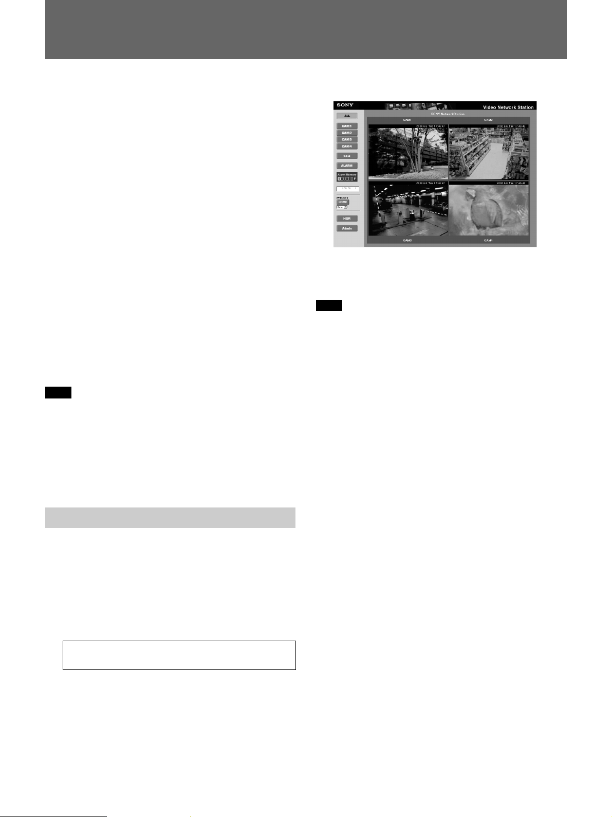
The monitor screen shows either the Camera view or
HSR view (the above example is the Camera view). A
system setting determines which is displayed initially.
Note
•Up to eight users can be logged on at the same time.
•If the network bandwidth setting is too slow, all
images in the four-screen display of the ALL mode of
the Camera view may not display properly. In this
case, either increase the network bandwidth, or
change the All mode setting to two-screen display.
•When a proxy server is present on the network, old
data stored in the proxy server may be displayed. In
this case, change settings to bypass the proxy server.
•A large volume of data is sent to the video network
station while monitoring images. When accessing the
video network station using a modem, images should
be monitored only under the following conditions.
Settings on the Administration Overview page are not
accessible by modem.
– Set the [Baud Rate] for the modem to 38 kbps or
higher.
– Set video input [Quality] to [High] or less.
– Set the image size to [Fullsize].
– Set the image display to one image only.
– Do not control the EVI-D30/D31/G20/G21 from
the PC.
– The pop-up window display is disabled when
reviewing alarm events.
– Automatic display switching to the alarm camera
when an alarm event occurs is disabled.
•Modem and Ethernet connections cannot both be
used at the same time.
•If the computer used for viewing the monitor screen
is shared with other users, we recommend closing the
Web browser when finished operations. Until the
browser has been closed, even after moving to
another Web page, the password-protected video
network station’s Web page remains accessible, for
example, by clicking the [Back] button.
25
Operation
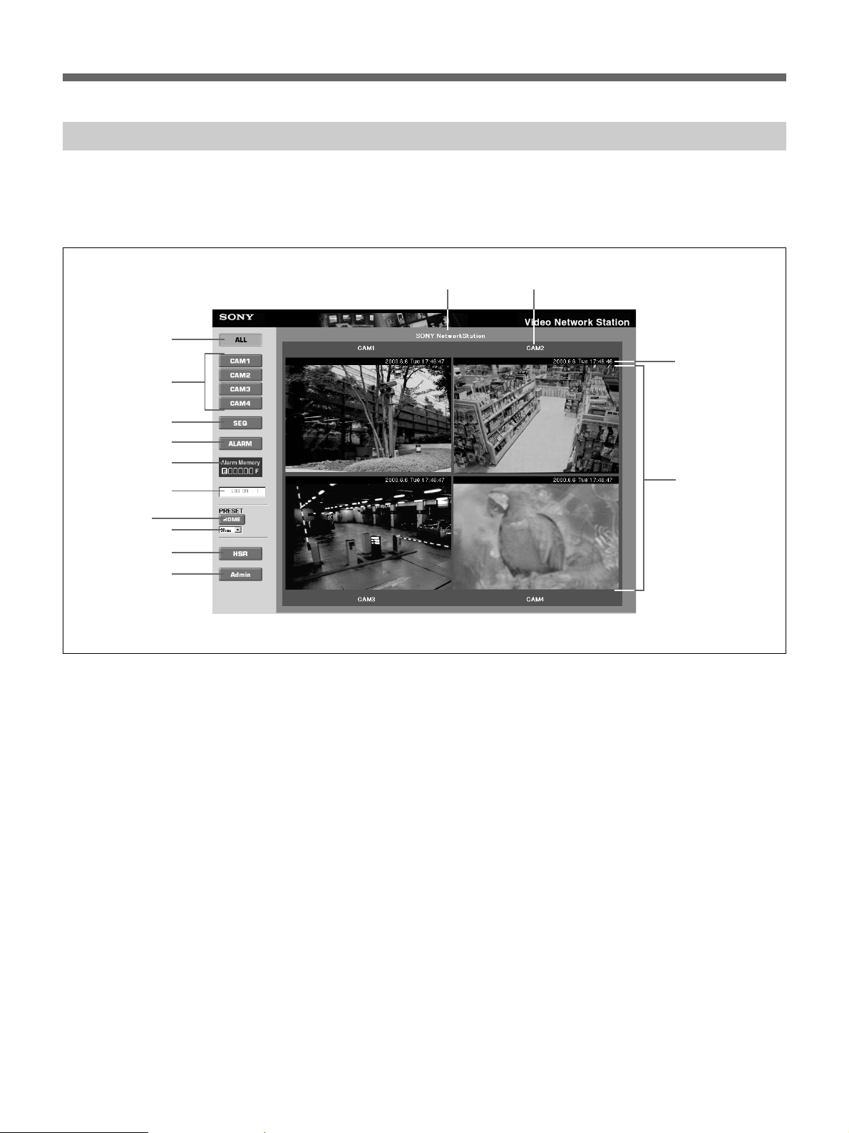
Camera View Operations
The Camera View displays the video camera images.
Use the screen buttons and icons to switch between
cameras and display modes.
1
2
3
4
5
6
qa qs
qd
qf
7
8
9
0
1 [ALL] Button
Clicking this button switches the monitor screen to the
ALL mode (as shown in the above example). In this
mode, images from the video cameras connected to the
video network station are displayed in two or four
partitions.
2 [CAM1] to [CAM4] Buttons
Clicking one of these buttons changes the monitor
screen to the Single mode, in which only one video
camera image is displayed. Each button corresponds to
one of the video input terminals (“VIDEO 1” to
“VIDEO 4”) on the video network station. Buttons
corresponding to disabled video input terminals are not
displayed.
3 [SEQ] Button
Clicking this button changes the monitor screen to the
Sequential mode, in which the image from each video
camera is displayed one at a time, switching from one
camera to the next at preset intervals.
4 [ALARM] Button
Clicking this button changes the monitor screen to the
Alarm mode, which allows searching images or
replaying video when an alarm has occurred. Refer to
“Viewing Alarm Event Images” on page 29 for details.
5 [ALARM MEMORY] Indicator
Images acquired when alarm events occur are stored in
the memory of the video network station. The amount
of available memory is indicated in seven steps from
“E” (empty) to “F” (full).
6 Users Logged On
Shows the number of users logged on to the video
network station. The value for the number of users
logged on is only an approximation.
7 [HOME] Button
Returns the video camera to the home position.
26

8 [PRESET] Drop-Down List
Select a preset camera position by name from this list
to set the camera to that fixed position (previously set
by the system administrator).
9 [HSR] Button
Clicking this button changes to the HSR view, in
which images of video cameras connected to an HSR1/1P/2/2P can be monitored, and the HSR-1/1P/2/2P
can be controlled. Refer to the “HSR View Mode” on
page 33 for details.
0 [Admin] Button
Clicking this button displays the “Administration
overview” page, where video network station settings
and management can be performed. Access to this
page is normally restricted to the system administrator.
qa Site Name
This is the name assigned to the overall video network
station system.
qs Camera Title
This is the title of the video camera.
qd Date and Time
This is current date and time.
qf Video Camera Images
Clicking at a point in an image causes the video
camera to pan and tilt so that the clicked point
becomes the center of the image.
27
Operation
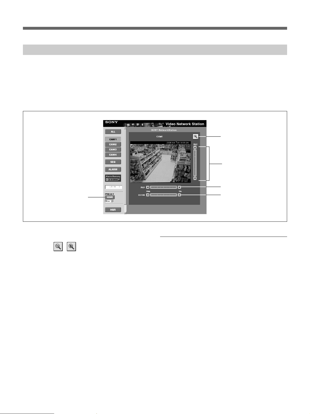
Pan/Tilt/Zoom Control
When an EVI-D30/D31/G20/G21 is connected to a
serial port on the video network station, camera pan,
tilt and zoom can be controlled from the Web page.
The monitor screen must be set to the Single mode
Camera View: click one of the [CAM1] to [CAM4]
buttons, if necessary, to change to the Single mode
5
Camera View. The Pan/Tilt/Zoom control bars are
displayed around the video source image in the Single
mode.
z Hint
The Pan/Tilt/Zoom functions described here are not
available if disabled by the system administrator.
1
2
3
4
1 Image Resize Icons
Clicking this
between [Fullsize] and [Hugesize].
2 Tilt Control Bar
Controls tilt (up/down movement) of the video camera.
3 Pan Control Bar
Controls pan (left/right movement) of the video
camera.
4 Zoom Control Bar
Controls zooming of the video camera.
5 [HOME] Button
Returns the video camera to the home position.
/ icon switches the image size
Pan/Tilt/Zoom Control Operation
Video camera pan, tilt and zoom can be controlled by
the following methods.
Step
Clicking a triangle at the top, bottom, left or right of
the Pan or Tilt control bar causes the video camera to
move by a single step, equal to about five degrees of
angle.
Positioning
Clicking a position on the Pan/Tilt/Zoom control bar
causes the video camera to be repositioned in a
corresponding manner. In the case of zooming, the
video camera zooms as directed.
Target
Clicking at a point in an image causes the video
camera to pan and tilt (so the clicked point becomes
the center of the image).
28
 Loading...