

Page 1

C-357-100-11 (1)
Network Camera
Installation Manual
Before operating the unit, please read this manual thoroughly
and retain it for future reference.
SNC-VB770
© 2016 Sony Corporation
Page 2

Table of Contents
About the Manuals
About the Manuals .................................................... 2
Location and Functions of Part ............................... 3
Installation ................................................................. 7
Mounting the lens .................................................. 7
Mounting the wire rope ......................................... 8
Adjustment of shooting area and focus ................. 8
Connection ................................................................. 9
Connection to the network ..................................... 9
Connection to the power supply ............................ 9
Connection to DC 12 V or AC 24 V ...................... 9
Connection to PoE power supply equipment ......... 9
Assigning the IP address .......................................... 9
Specifications ........................................................... 10
Safety Regulations (supplied)
The Safety Regulations describes the secure usage of
camera. Be sure to read it.
Installation Manual (this document)
This Installation Manual describes the names and
functions of parts and controls of the Network Camera,
gives connection examples and explains how to set up the
camera. Be sure to read the Installation Manual before
operating.
User’s Guide/Application Guide/SNC
toolbox mobile Application Guide (Web)
• How to control the camera via a web browser
• How to setup the camera
• How to adjust the view angle of the camera using a
smartphone or tablet
Operate the camera referring to the guide above after
having installed and connected the camera properly based
on the Installation manual.
2
Page 3
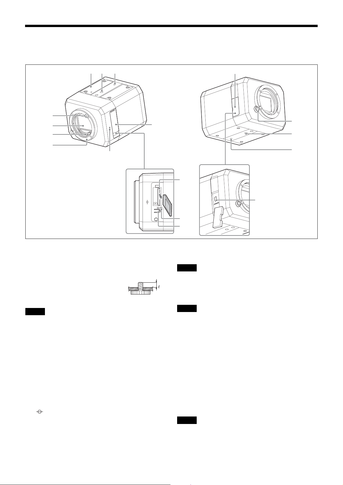
Location and Functions of Part
9
8
7
6
5
3
4
qf
2
3
q;
qg
qa
qs
1 2qd
a Rating label
This label shows the name of the device and its electric
rating.
b
Tripod mounting screw holes
Use this to fix the camera on the
camera tripod.
Note
1/4"-20 UNC
4= 4.5 mm to 7 mm
(with screw tightened)
Using screws other than 4.5 mm - 7 mm may cause a
malfunction due to faulty mounting or internal damage of
the camera.
c Screw hole to attach anti-drop wire rope
Attach supplied wire rope with supplied screws.
d SD memory card cover
When using the SD memory card slot, insert an SD
memory card by opening the card slot.
e Image sensor position mark
The mark describes the position on the image sensor.
Use the position of this line to measure the distance from
the camera to objects correctly.
f Mount
Mount the E-mount lens.
g Lens contacts
Note
Do not touch directly with your hands.
h Image sensor
Note
Do not touch directly with your hands.
i Mount index
j SD memory card slot
SD memory card (sold separately) can be attached.
You can record the images stored on the camera to the SD
memory card by attaching the SD memory card.
Insert it with the terminal facing the rear side as indicated
in the illustration. Then press it down softly until it clicks
to attach firmly.
The camera only supports memory cards with
SDXC standards and SDHC standards.
Note
Please contact the Sony inquiry counter for verified SD
memory cards.
3
Page 4

k SD MOUNT (SD mount) indicator
Lights on while an SD memory card is mounted.
l SD OFF switch
You can remove the SD memory card safely by pressing
the switch.
Remove the card after the SD MOUNT indicator goes off.
Notes
• The card may be damaged if you remove it while the
indicator is on.
• If you press the SD OFF switch while writing to the SD
memory card, the data written just before could be lost.
m HDMI cover
When using a commercially available HDMI cable,
connect the cable to the HDMI connector by opening.
n Lens release button
To remove the lens, rotate the lens by pressing the button.
When you mount the lens, do not press the button.
o HDMI connector (Type D)
Connect a commercial HDMI cable.
Notes
• It is recommended to secure the HDMI cable to prevent
it from disconnecting from the camera due to its weight
or from external force.
• Do not wire the HDMI cable with the cable routed
outdoors. Also, in case you wire indoors, do not make
the cable longer than 30 m.
4
Page 5
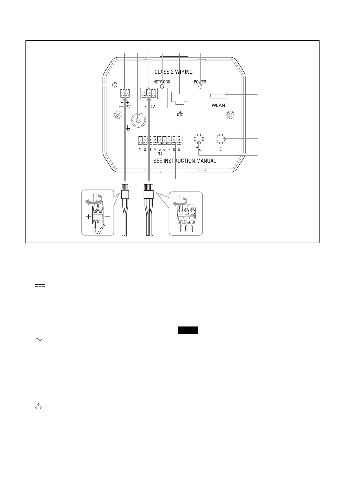
Rear side
1
24
3567
qa
8
9
q;
a Reset switch
When you supply power while pressing this switch with
pointed things, it is reset to the factory setting.
b 12 V (DC power input) terminal
Connects to a DC 12 V power supply.
c U Screws for ground wire
If you supply the power via DC 12 V or PoE, make sure to
connect the ground wire to the screw for the ground wire.
d 24 V (AC power input) terminal
Connects to the AC 24 V power supply.
Make sure to connect the ground earth to the center (U) of
the 3-pin terminal.
e NETWORK (network) indicator
Lights or blinks when it is connected to the network. It is
off when it is not connected to the network.
f LAN (network) port (RJ-45)
Perform PoE* power supply or network communication
using commercial network cables (UTP, category 5).
For details on the connection, please refer to the operating
instructions on the power supply equipment.
(*PoE: abbreviation of Power over Ethernet. PoE is
compliant with IEEE802.3af)
g POWER (power) indicator (green)
When the power is supplied to the camera, system check is
performed within the camera.
Lights up in green, when the camera is operating normally.
h WLAN (wireless LAN terminal)
Attach Sony USB wireless LAN module IFU-WLM3
(WLAN module, sold separately).
Use this to adjust the view angle on installation.
Notes
• Wired LAN doesn’t work when a WLAN module is
attached.
• If the output mode is set to 4K Multi streaming, 4K
25fps, or 4K 30fps, it will be automatically switched to
Full HD when the WLAN module is attached. Make sure
to reset the output mode to the original setting after the
WLAN module is removed.
For details on settings, please refer to the User Guide.
• Using devices other than those specified may lead to
faults or malfunctions.
• Use WLAN in an environment with outside temperature
between 0 °C (32 °F) and 40 °C (104 °F).
• If the WLAN module is covered by metal such as
housing while WLAN is being used, the radio wave
reception becomes poor and may not work.
5
Page 6
i 5 (line output) terminal (mini-jack, monaural)
This is not used in this version.
If the speaker is connected, noise may sometimes occur.
This is not a fault, but it is due to the electromagnetic
block.
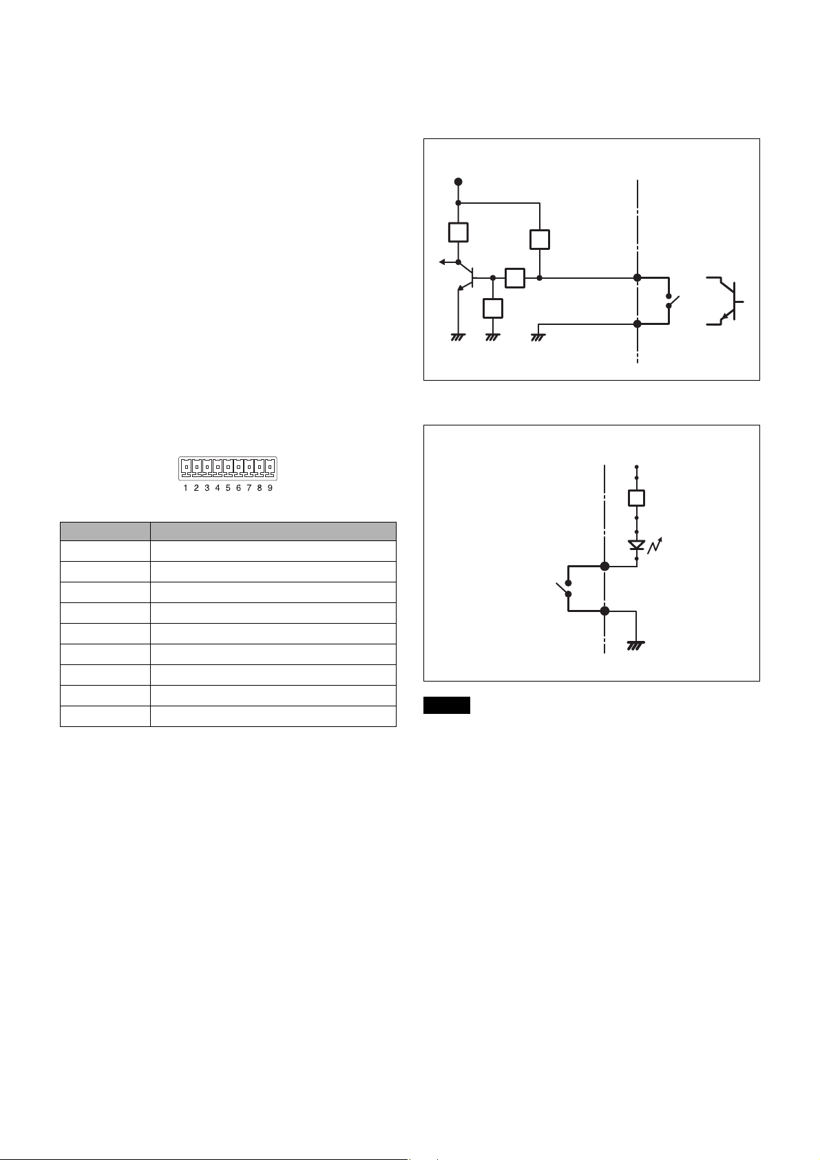
Connection to I/O cable
Mechanical switch/open collector output
equipment
j
m (microphone/line input) terminal (mini-jack,
monaural)
Switch between
m (microphone/line) terminal (mini jack,
monaural) microphone input and line input in the Video/
Audio menu.
For details on settings, please refer to the User Guide.
• Microphone input terminal
Connect the commercial microphone.
This terminal supports plug-in power system (basic
voltage: 2.5 VDC).
k I/O (input/output) port
Equipped with 2-system sensor inputs, 2-system alarm
outputs.
Each pin supports the signals below.
Pin No. Name
1 Alarm input 1
2 Alarm input 2
3 GND
4 Alarm output 1+
5 Alarm output 1–
6 Alarm output 2+
7 Alarm output 2–
8 Extended terminal
9 Extended terminal
◆
Refer to the User’s Guide for details on each function
and setting.
Wire as shown below for each wire of the I/O cable.
3.1 V
10 kΩ
GND GND GND
Inside of the camera
2.2 kΩ
10 kΩ
10 kΩ
Sensor input+ Mechanical switch
Sensor input –
(GND)
Outside
or
Open collector
Output equipment
Connection diagram
Inside of the camera 5 V
Alarm output +
Alarm output –
GND
Note
Outside
R
Line example
Cables should be connected without routing to the outside
when 2, q;, or qa is connected.
When you wire the cable with the cable routed indoors,
2, q;, or qa should be wired under 30 m.
6
Page 7
Installation
Warning
• Do not leave the lens facing the sun.
The sunlight will focus inside the camera and might
cause a fire.
• When installing the camera, make sure there is space
between the camera and the surface, such as the ceiling,
etc., where the camera is installed. If there is no space
between the camera and the surface, the temperature
inside gets high and may lead to failure or accident.
• Make sure to attach the supplied wire rope to prevent
accidents due to falling.
• Attach the lens in the exact way described in this
document. Loose attachment may lead to injury due to
the lens falling off.
• Check that the attachment is not loose at least once a
year. Perform more frequent checks depending on the
usage.
• Full performance may not be achieved depending on the
installed circumstance or lens. Please contact Sony for
details.
2
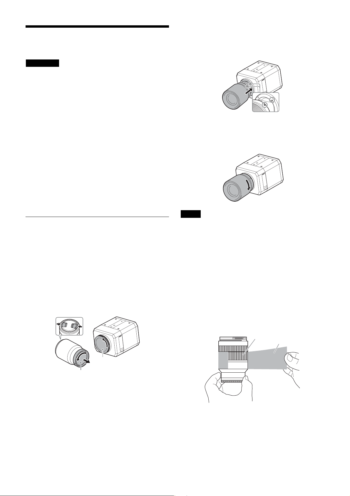
Align the white dots on the lens and camera, then
attach.
• Face the mount downward, to prevent dust from
getting in.
3
Push the lens against the camera lightly then rotate it
in the direction of the arrow until it clicks.
• Do not insert the lens at a tilted angle.
Mounting the lens
Mounting/removing of the lens should be performed after
turning the camera “OFF”.
1
Remove the body cap from the camera and the lens
rear cap from the lens.
• Perform this operation in a non-dusty place in a
quick manner to prevent dust from getting into the
camera.
• Remove the lens front cap on the front side of the
lens when you shoot.
Lens front cap
Body cap
Lens rear cap
Notes
• When you mount the lens, do not press the Lens release
button.
• Do not apply excessive force on the lens.
• Securely hold both the camera and lens when you carry
the camera with lens mounted.
• Do not hold the camera by holding the lens part when it
is protruding when zooming or focusing.
• Zoom lens use
Zoom position may be changed depending on the
installation circumstances.
Make sure to fix it by applying tape on the zoom ring.
Recommended tape: 3M Scotch
Model No. 471 BLA 50 equivalents
Apply tape on the zoom ring full circle to fix.
®
Zoom ring
plastic film tape
Ta p e
7
Page 8
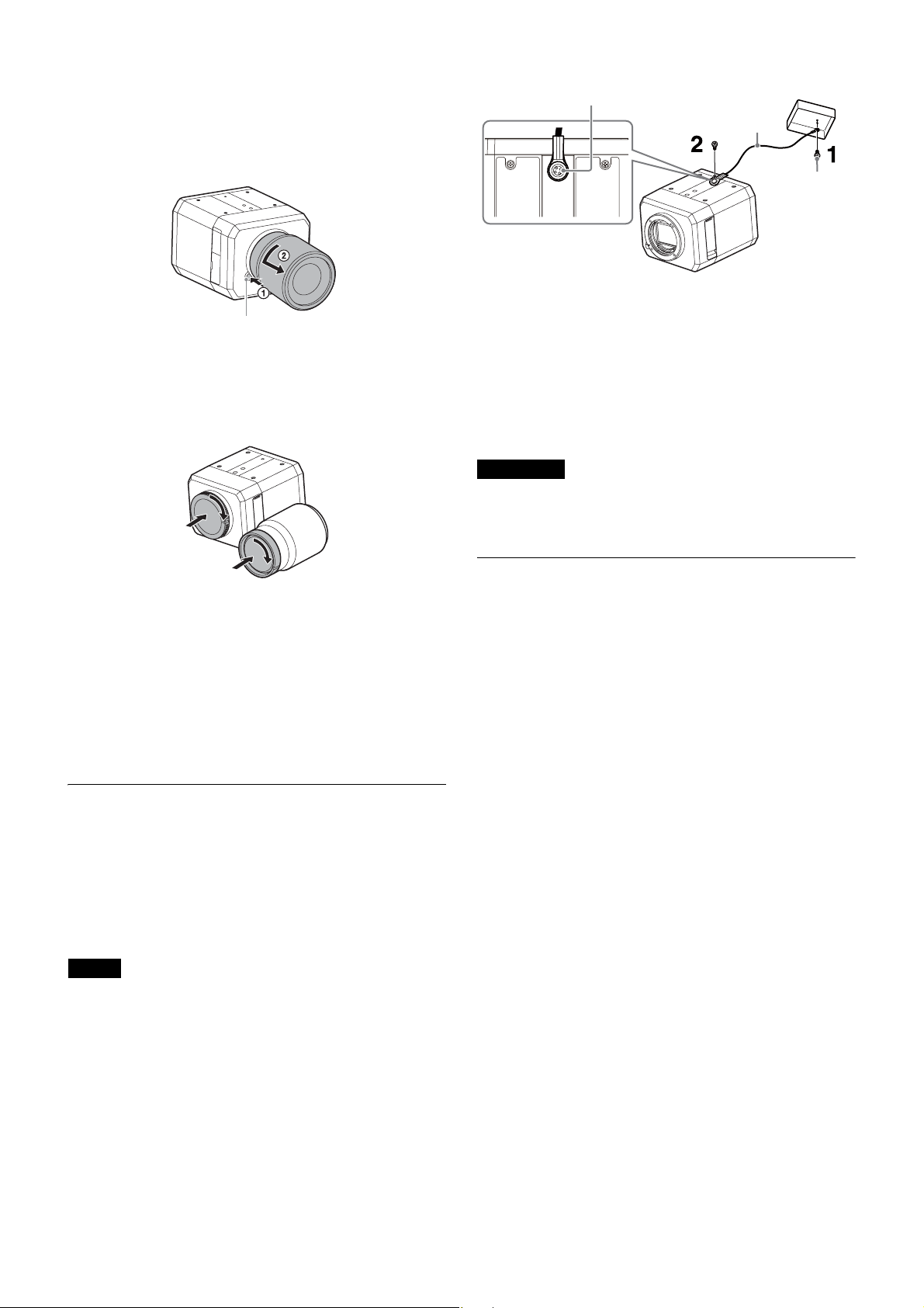
To remove the lens
1
Rotate the lens in the direction of the arrow until it
stops while pressing the Lens release button, then
remove.
Lens release button
2
Mount the body cap on the camera, and the cap on the
front and back of the lens.
• Mount the cap after removing dust.
Mounting screw (supplied)
Wire rope (supplied)
Screw
(not supplied)
1
Mount the wire rope to the junction box on the ceiling.
Use screws which fit the screw holes on the junction
box (not supplied).
2
Mount the wire rope with the supplied wire rope
mounting screws to the wire rope mounting screw
holes on the camera.
Warning
Use the supplied screws for mounting. Otherwise, the wire
rope may not function effectively.
Notes on lens exchange
If dust get into the camera and is stuck to the surface of the
image sensor (a part to convert the light to electrical
signals) upon the lens exchange, the dust may appear in the
image.
Mount/remove the lens at a location with little or no dust
in a quick manner.
Mounting the wire rope
Make sure to attach the supplied wire rope to prevent
falling accidents when you install the camera on the ceiling
or at substantial heights.
Attach the wire rope with supplied mounting screws
(illustrated in below) to the wire rope mounting screw
holes on the rear side of the camera.
Note
When you mount the wire rope, be careful when wiring to
prevent wire rope from short circuiting with a power
source terminal or cable.
Adjustment of shooting area and focus
Determine the shooting area by adjusting the view angle
and focus while reviewing the image.
Adjust the view angle following the operating instructions
of the mounted lens.
Adjust the focus with SNC toolbox or SNC toolbox
mobile.
Adjustment by using SNC toolbox mobile
You can adjust the view angle easily by installing SNC
toolbox mobile on your smartphone or tablet.
If you insert IFU-WLM3 (sold separately), select the SSID
shown below under Wi-Fi settings on your smartphone.
SNC-[Mac address of IFU-WLM3]
Example:
Display with SSID with IFU-WLM3, when the Mac
address is 00-11-22-33-44-55:
SNC-001122334455
The default value of the password is shown below.
Password: T8qUDTUuFyb8a
Please refer to the SNC toolbox mobile application guide
on the Web site.
8
Page 9

Connection
Connection to the network
Assigning the IP address
1
Download the installer of “SNC toolbox” to a folder
from the following URL:
Connect the LAN port on the camera to the router or hub
of the network, using a commercial network cable.
Connection to the power supply
The camera can connect the power supply in 3 ways as
shown below.
• DC 12 V
•AC 24 V
• PoE* (Compliant with IEEE802.3af)
(*PoE: an abbreviation of Power over Ethernet)
Notes
• Supply either DC 12 V, AC 24 V, or PoE.
• Do not connect AC 24 V to the DC power input terminal.
Otherwise it will lead to failure.
Connection to DC 12 V or AC 24 V
Connect the camera’s power input cable to the DC 12 V or
AC 24 V power supply equipment.
• Use the power insulated from the AC 100V for DC 12 V
or AC 24 V. The power usage range for each power
supply is shown below. (warranty scope of the power
received on the camera, voltage at receiving end)
DC 12 V: 9 V to 15 V
AC 24 V: 19.2 V to 28.8 V
• Use UL cable (VW-1 style 10368) for wiring for
DC 12 V or AC 24 V.
• Recommended power cable
Voltage at receiving end on the camera is DC 12 V
www.sony.net/CameraSystem
2
Install the SNC toolbox.
Unzip the ZIP file of the downloaded installer.
Double-click “SncToolbox_Setup.exe.”
For details on installing and use refer to the
Application Guide.
3
Assign an IP address to the camera.
Assign an IP address to the camera using the installed
SNC toolbox.
For details, see “Using SNC toolbox” - “Assign an IP
address” in the Application Guide.
Tip
SNC toolbox stands for Sony Network Camera
toolbox.
Cable (AWG) #20 #18 #16
The maximum cable
length (m)
Voltage at receiving end on the camera is AC 24 V
Cable (AWG) #20 #18 #16
The maximum cable
length (m)
10 20 30
60 110 180
Connection to PoE power supply equipment
PoE (Compliant with IEEE802.3af) power supply
equipment supplies power via commercial network cables.
Please refer to the operating instructions on the power
supply equipment.
9
Page 10

Specifications
Camera
Image sensor 35 mm full frame Exmor® CMOS sensor
Number of Effective Pixels Approx. 12.2 Megapixels
Lens type E-mount lens (option)
Sync System Internal synchronization
Minimum Illumination (30 IRE) 0.004 lx (1/30s, F1.4)
Video
Image Compression Format H.264 (High/Main Profile), JPEG
H.264 (B-picture) supports the resolution below.
3,840 × 2,160
2,880 × 2,160
Maximum Frame Rate H264: 30 fps (3,840 × 2,160)/30 fps (1,920 × 1,080)
JPEG: 2.5 fps (4,240 × 2,832)
Audio
Compression Format G.711 (bit rate: 64 kbps, sampling frequency: 8 kHz)
G.726 (bit rate: 40, 32, 24, 16 kbps, sampling frequency: 8 kHz)
AAC-LC (bit rate: 64 kbps, sampling frequency: 16 kHz)
AAC-LC (bit rate: 128 kbps, sampling frequency: 48 kHz)
Interface
Digital Video Output HDMI (type D) × 1
Microphone Input Mini jack (monaural, 2.2 kΩ, plug-in-power)
Line Input Mini jack (monaural)
Network port 10BASE-T/100BASE-TX (RJ-45)
Alarm input (sensor input) 2 ports (MAKE contact, BREAK contact)
Alarm output 2 ports (solid-state relay Max. AC 12 V/DC 24 V, 0.4 A) (electrically isolated
from the camera)
Wireless LAN terminal Supports the accessory IFU-WLM3 (sold separately)
Memory card slot SD memory card slot (supports SDHC/SDXC memory cards) × 1
General
Power Requirements PoE (Compliant with IEEE802.3af)
DC 12 V ± 25 %, AC 24 V ± 20 %, 50/60 Hz
Power Consumption Max. approx. 16W (including lens)
Operating temperature
When power is turned on
While on
Storage Temperature –20°C to +60°C
Operating Humidity 20 % to 80 % (no condensation)
Storage Humidity 20 % to 80 % (no condensation)
0°C to 50°C
–5°C to +50°C
10
Page 11
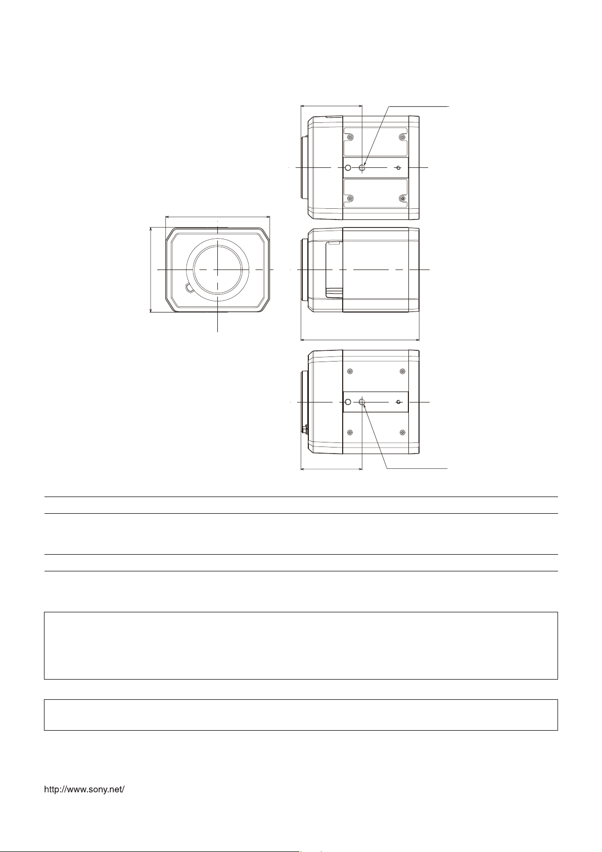
Outer dimensions (W × H × D) 104 mm × 84.6 mm × 118 mm (without projection)
[The values for dimensions are approximate.]
61 (2 1/2) 1/4"-20 UNC
104 (4 1/8)
84.6 (3 3/8)
118 (4 3/4)
61 (2 1/2)
1/4"-20 UNC
Unit: mm (inches)
Mass Approx. 720 g (Camera itself only)
Supplied Accessories Wire rope (1), Screws (M4×8) (1), 9-pin connector for I/O terminal (1), 2-pin
connector for DC power supply (1), 3-pin connector for AC power supply (1),
Safety Regulations (1)
Optional Accessories IFU-WLM3 (USB wireless LAN module)
Design and specifications are subject to change without notice.
Recommendation of Periodic Inspections
If you are using this device for over an extended period of time, please have it inspected periodically for safe use.
It may appear flawless, but the components may have deteriorated over time, which may cause a malfunction or
accident.
For details, please consult the store of purchase or an authorized Sony dealer.
Note
The Network Camera is to be connected only to PoE networks without routing to the outside plant.
11
 Loading...