

Page 1

Network Camera
3-990-921-11 (1)
User’s Guide
Software Version 1.0
SNC-RZ50N/RZ50P
© 2005 Sony Corporation
Page 2

Owner’s Record
The model and serial numbers are located on the bottom.
Record these numbers in the spaces provided below.
Refer to these numbers whenever you call upon your
Sony dealer regarding this product.
Model No. ____________________
Serial No. ____________________
For customers in the U.S.A. (SNC-RZ50N
only)
This device complies with Part 15 of the FCC Rules.
Operation is subject to the following two conditions:
(1) This device may not cause harmful interference,
and (2) this device must accept any interference
received, including interference that may cause
undesired operation.
WARNING
To reduce a risk of fire or electric shock,
do not expose this product to rain or
moisture.
To avoid electrical shock, do not open the
cabinet. Refer servicing to qualified
personnel only.
AC power adaptor
Model No.: MPA-AC1 (Sony)
CAUTION: This unit is for use only with the supplied
AC power adaptor. Use with other AC
power adaptors may cause hazards such as
a fire.
WARNING
This installation should be made by a qualified service
person and should conform to all local codes.
WARNING
A readily accessible disconnect device shall be
incorporated in the building installation wiring.
WARNING (for Installers only)
Instructions for installing the equipment on the ceiling:
After the installation, ensure the connection is capable
of supporting five times the weight of the equipment
downwards.
CAUTION
The rating label is located on the bottom.
CAUTION for LAN port
For safety reason, do not connect the LAN port to any
network devices that might have excessive voltage.
NOTE: This equipment has been tested and found to
comply with the limits for a Class A digital device,
pursuant to part 15 of the FCC Rules. These limits are
designed to provide reasonable protection against
harmful interference when the equipment is operated in
a commercial environment. This equipment generates,
uses, and can radiate radio frequency energy and, if not
installed and used in accordance with the instruction
manual, may cause harmful interference to radio
communications. Operation of this equipment in a
residential area is likely to cause harmful interference in
which case the user will be required to correct the
interference at his own expense.
You are cautioned that any changes or modifications not
expressly approved in this manual could void your
authority to operate this equipment.
The shielded interface cable recommended in this
manual must be used with this equipment in order to
comply with the limits for a digital device pursuant to
Subpart B of Part 15 of FCC Rules.
For customers in Canada (SNC-RZ50N
only)
This Class A digital apparatus complies with Canadian
ICES-003.
Cet appareil numérique de la classe A est conforme à la
norme NMB-003 du Canada.
For customers in other countries
WARNING
This is a Class A product. In a domestic environment,
this product may cause radio interference in which case
the user may be required to take adequate measures.
In the case that interference should occur, consult your
nearest authorized Sony service facility.
2
Page 3

ATTENTION
The electromagnetic fields at specific frequencies may
influence the picture of the unit.
For the customers in Netherlands
Voor de klanten in Nederland
Gooi de batterij niet weg, maar lever
hem in als KCA.
NOTICE TO USERS
© 2005 Sony Corporation. All rights reserved. This
manual or the software described herein, in whole or in
part, may not be reproduced, translated or reduced to
any machine readable form without prior written
approval from Sony Corporation.
SONY CORPORATION PROVIDES NO
WARRANTY WITH REGARD TO THIS MANUAL,
THE SOFTWARE OR OTHER INFORMATION
CONTAINED HEREIN AND HEREBY EXPRESSLY
DISCLAIMS ANY IMPLIED WARRANTIES OF
MERCHANTABILITY OR FITNESS FOR ANY
PARTICULAR PURPOSE WITH REGARD TO THIS
MANUAL, THE SOFTWARE OR SUCH OTHER
INFORMATION. IN NO EVENT SHALL SONY
CORPORATION BE LIABLE FOR ANY
INCIDENTAL, CONSEQUENTIAL OR SPECIAL
DAMAGES, WHETHER BASED ON TORT,
CONTRACT, OR OTHERWISE, ARISING OUT OF
OR IN CONNECTION WITH THIS MANUAL, THE
SOFTWARE OR OTHER INFORMATION
CONTAINED HEREIN OR THE USE THEREOF.
Sony Corporation reserves the right to make any
modification to this manual or the information contained
herein at any time without notice.
The software described herein may also be governed by
the terms of a separate user license agreement.
• “IPELA” and are trademarks of Sony
Corporation.
• “VISCA” is a trademark of Sony Corporation.
• Microsoft, Windows, Internet Explorer and MS-DOS
are registered trademarks of Microsoft Corporation in
the United States and/or other countries.
• Java is a trademark of Sun Microsystems, Inc. in the
United States and other countries.
• Intel and Pentium are registered trademarks of Intel
Corporation or its subsidiaries in the United States and
other countries.
• Adobe, Acrobat and Adobe Reader are trademarks of
Adobe Systems Incorporated in the United States and/
or other countries.
• CompactFlash and CF are trademarks of SanDisk
Corporation, registered in the United States and other
countries.
All other company and product names are trademarks or
registered trademarks of the respective companies or
their respective makers.
3
Page 4

Table of Contents
Controlling Day/Night Function .........................26
Playing the Audio File Stored in the Camera ....27
Switching TCP/UDP Transmission Mode ..........27
Overview
Features .................................................................. 6
How to Use This User’s Guide .............................. 7
Precautions ............................................................. 7
Operating precautions ........................................ 7
System Requirements ............................................ 8
Preparation
Assigning the IP Address to the Camera ............ 9
Assigning an IP address using the Setup
Program ............................................................ 9
Accessing the Camera Using the Web Browser 11
Basic Configuration by the Administrator ....... 13
Operating the Camera
Administrator and User ...................................... 14
Logging in to Homepage — Welcome Page ...... 15
Logging in as a user ......................................... 15
Displaying the Administrator menu directly .... 16
About viewers .................................................. 16
Configuration of Main Viewer ........................... 17
Main menu ....................................................... 18
Camera control section ..................................... 18
Monitor image .................................................. 19
Controlling the Monitor Image .......................... 20
Monitoring the camera image .......................... 20
Zooming in the monitor image ......................... 20
Capturing a Monitor Image ............................... 21
Capturing a monitor image .............................. 21
Saving the captured image ............................... 21
Operating the Camera ........................................ 22
Controlling via the control panel ..................... 22
Panning and tilting by clicking the monitor
image .............................................................. 22
Panning, tilting and zooming by specifying the
area ................................................................. 22
Zooming an image by the camera zoom bar .... 23
Moving the camera to a preset position ........... 23
Controlling the Camera on a Panorama Image 24
Facing the camera toward a specified point ..... 24
Sending an Image File ......................................... 25
Sending a monitor image via e-mail ................ 25
Sending a monitor image to an FTP server ...... 25
Recording a Still Image in the Memory ............ 25
Controlling Alarm Output 1, 2 ........................... 26
Administrating the Camera
Basic Operations of Administrator Menu .........29
How to setup the Administrator menu ..............29
Configuration of Administrator menu ..............30
Configuring the System — System Menu ..........32
System Tab ........................................................32
Date & time Tab ................................................33
Initialize Tab .....................................................34
System log Tab .................................................35
Access log Tab ..................................................35
Setting the Camera Image and Audio
— Camera Menu ..................................................36
Common Tab ....................................................36
Picture Tab ........................................................37
Day/Night Tab ..................................................38
Video codec Tab ...............................................39
Streaming Tab ...................................................40
Configuring the Network — Network Menu .....41
Network Tab ..................................................... 41
Wireless Tab — Setting of wireless
connection .......................................................42
Dynamic IP address notification Tab — Notifying
the IP Address .................................................44
Setting the User — User Menu ...........................45
Setting the Security — Security Menu ...............46
Saving the Camera Position and Action — Preset
position Menu .......................................................47
Position Tab — Saving pan/tilt/zoom position .47
Tour Tab — Setting a tour ................................48
Sending an Image via E-mail — e-Mail (SMTP)
Menu .....................................................................50
Common Tab — Setting the e-Mail (SMTP)
Function ..........................................................50
Alarm sending Tab — Setting the e-mail sending
mode when detecting the alarm ......................51
Periodical sending Tab — Setting the periodical e-
mail sending mode ..........................................52
Sending Images to FTP Server — FTP client
Menu .....................................................................53
Common Tab — Setting the FTP client
function ...........................................................53
Alarm sending Tab — Setting the FTP client
action when detecting the alarm .....................53
Periodical sending Tab — Setting the periodical
FTP client activity ..........................................54
Recording Images in Memory — Image memory
Menu .....................................................................55
4
Table of Contents
Page 5

Common Tab — Setting the image memory
function .......................................................... 55
Alarm recording Tab — Setting the Image
memory function when detecting the alarm ... 56
Periodical recording Tab — Setting the periodical
recording mode ............................................... 57
Folder structure of image memory ................... 58
Downloading Images from the Camera — FTP
server Menu .........................................................59
Setting the Alarm Output — Alarm output
Menu ..................................................................... 59
Alarm out 1, 2 Tab ............................................ 59
Outputting Audio Linked to Alarm Detection
— Voice alert Menu ............................................. 60
Setting the Operations from the Viewer — Trigger
Menu ..................................................................... 61
Setting the Schedule — Schedule Menu ............ 63
Setting the Alarm Buffer — Alarm buffer
Menu ..................................................................... 64
Setting the Object Detection Function
— Object detection Menu ................................... 65
What is unattended object detection? ............... 65
Common Tab .................................................... 66
Unattended object setting Tab .......................... 71
Configuration Tab .............................................71
Transmitting with External Equipment Using the
External Serial Terminal — Serial Menu .......... 72
Using the Custom Homepage Installer ..............82
Uploading the homepage to the camera using the
Custom Homepage Installer ...........................82
Assigning the IP Address to the Camera Using
ARP Commands ...................................................84
Using the SNMP ...................................................85
1. Inquiry Commands ......................................85
2. Setting Commands .......................................85
Specifications ........................................................87
When You Discard the Camera ..........................88
Glossary ................................................................89
Index ......................................................................91
Others
Using the Supplied Setup Program .................... 73
Starting the Setup Program .............................. 73
Bandwidth control Tab ..................................... 73
Date time Tab ................................................... 74
Rebooting the Camera ...................................... 74
Using the SNC audio upload tool — Transmitting
Audio to Camera .................................................. 75
Installing the SNC audio upload tool ............... 75
Connecting the Camera to the Computer ......... 75
Using the SNC audio upload tool .....................76
Using the SNC video player — Playing Video/
Audio File Recorded with Camera ..................... 78
Installing the SNC video player ....................... 78
Using the SNC video player ............................. 79
Using the SNC panorama creator
— Creating a Panorama Image .......................... 80
Installing the SNC panorama creator ............... 80
Using the SNC panorama creator ..................... 80
Preparing connection to the camera ................. 81
Creating and transmitting a panorama image ... 81
Saving a custom image to the camera .............. 81
Table of Contents
5
Page 6

Overview
• You should keep in mind that the images or audio
you are monitoring may be protected by privacy
and other legal rights, and the responsibility for
making sure you are complying with applicable
laws is yours alone.
• Access to the images and audio is protected only
by a user name and the password you set up. No
further authentication is provided nor should you
presume that any other protective filtering is done
by the service. Since the service is Internet-based,
there is a risk that the image or audio you are
monitoring can be viewed or used by a third-party
via the network.
Overview
Features
If you use the CF card slot, insert the Sony wireless card
SNCA-CFW1 (optional) in it. If you use the PC card
slot, use with a commercially available Compact Flash
Type II-PCMCIA converting adaptor.
Image transmission using an e-mail or
FTP
You can send a still image from the camera as an e-mail
or FTP server, attachment by setting off a trigger using
an external sensor input, built-in object detection
function or manual trigger button. You can also send still
images sequentially for a determined period before and
after the trigger to an FTP server, or send them
periodically.
Preset positions and Tour programs
You can save up to 16 preset positions (pan, tilt and
zoom positions) of the camera, and up to 5 tour
programs composed from the preset positions. You can
activate the preset positions by synchronizing them with
an external sensor input or built-in object detection
function.
High-quality monitoring via the network
You can monitor a high-quality live image from the
camera using the Web browser on a computer connected
to a 10BASE-T or 100BASE-TX network. The
maximum frame rate is 30 fps for SNC-RZ50N and 25
fps for SNC-RZ50P.
Up to 20 users can view an image from one camera at the
same time.
The camera supports JPEG and MPEG4 video
compression (video codecs) and can operate in either the
“Single codec” or “Dual codec” mode. The “Single
codec” mode allows monitoring in one of the two video
codecs, and the “Dual codec” mode allows monitoring
in JPEG and MPEG4 simultaneously.
Remote-controllable high-speed pan/tilt
mechanism and high magnification autofocus zoom lens
The camera is provided with a high-speed (300°
rotation/second) pan/tilt mechanism, which allows
–170° to +170° panning and –90° to +25° tilting. The
camera is also provided with a high-magnification zoom
lens with optical zoom of 26 magnifications and digital
zoom of 12 magnifications, for a total of 312
magnifications.
Intelligent object detection function
The camera is provided an intelligent object detection
function to watch images. This function combines
“Moving object detection” that detects moving objects
in camera images with “Unattended object detection”
that detects objects that do not move for a specified
period in camera images.
Alarm output
The camera is equipped with two sets of alarm outputs.
You can use the alarms to control peripheral devices by
synchronizing them with the external sensor inputs,
built-in object detection function, manual trigger button,
Day/Night function or timer.
Direct panning/tilting
Clicking on a desired point in the viewer allows you to
pan and tilt the camera in the direction of that point.
Dragging a desired area in the viewer allows you to
zoom in the dragged area as well as pan and tilt the
camera.
Wireless LAN
Inserting the optional SNCA-CFW1 wireless card into
the CF card slot or PC card slot enables you to transmit
images from the camera via wireless LAN (802.11b).
6
Features
Page 7

How to Use This User’s
Precautions
Guide
This User’s Guide explains how to operate the SNCRZ50N/RZ50P Network Camera from a computer.
The User’s Guide is written to be read on the computer
display.
As this section gives tips on using the User’s Guide, read
it before you operate the camera.
Jumping to the related page
When you read the User’s Guide on the computer
display, click on the sentence to jump to the related page.
Software display examples
Note that the displays shown in the User’s Guide are
explanatory examples. Some displays may be different
from the ones which appear as you operate the
application software.
Printing the User’s Guide
Depending on your system, certain displays or
illustrations in the User’s Guide, when printed out, may
differ from those as portrayed on your screen.
Installation Manual (printed matter)
The supplied Installation Manual describes the names
and functions of parts and controls of the Network
Camera, connecting examples and how to set up the
camera. Be sure to read the Installation Manual before
operating.
This Sony product has been designed with safety in
mind. However, if not used properly electrical products
can cause fires which may lead to serious body injury.
To avoid such accidents, be sure to heed the following.
Heed the safety precautions
Be sure to follow the general safety precautions and the
“Operating Precautions.”
In case of a breakdown
In case of system breakdown, discontinue the use and
contact your authorized Sony dealer.
In case of abnormal operation
• If the unit emits smoke or an unusual smell,
• If water or other foreign objects enter the cabinet, or
• If you drop the unit or damage the cabinet:
1
Disconnect the camera cable and the connecting
cables.
2
Contact your authorized Sony dealer or the store
where you purchased the product.
Operating precautions
Operating or storage location
Avoid operating or storing the camera in the following
locations:
• Extremely hot or cold places (Operating temperature:
0°C to +40°C [32°F to 104°F])
• Exposed to direct sunlight for a long time, or close to
heating equipment (e.g., near heaters)
• Close to sources of strong magnetism
• Close to sources of powerful electromagnetic
radiation, such as radios or TV transmitters
• Locations subject to strong vibration or shock
Overview
Ventilation
To prevent heat buildup, do not block air circulation
around the camera.
Transportation
When transporting the camera, repack it as originally
packed at the factory or in materials of equal quality.
Cleaning
• Use a blower to remove dust from the lens or optical
filter.
• Use a soft, dry cloth to clean the external surfaces of
the camera. Stubborn stains can be removed using a
soft cloth dampened with a small quantity of detergent
solution, then wipe dry.
• Do not use volatile solvents such as alcohol, benzene
or thinners as they may damage the surface finishes.
How to Use This User’s Guide / Precautions
7
Page 8

Overview
System Requirements
These are the requirements for the computer that
displays the image or controls the camera.
Processor
Intel Pentium 4, 1.5 GHz or higher (Pentium 4, 2.4 GHz
or higher recommended)
RAM
256 MB or more
OS
Microsoft Windows 2000, Windows XP
Web browser
Microsoft Internet Explorer Ver.6.0 or later
8
System Requirements
Page 9
Preparation
The Preparation section explains what the administrator
has to prepare for monitoring images after installation
and connection of the camera.
Assigning the IP
Address to the Camera
To connect the camera to a network, you need to assign
a new IP address to the camera when you install it for the
first time.
You can assign an IP address in two ways:
• Using the setup program stored in the supplied CDROM (see this page)
• Using the ARP (Address Resolution Protocol)
commands (see page 84)
This section explains how to assign an IP address to the
camera using the supplied setup program and how to
configure the network.
Before starting, connect the camera to a local network,
referring to “Connecting the Camera to a Local
Network” in the supplied Installation Manual.
Consult the administrator of the network about the
assigned IP address.
Assigning an IP address using the
Setup Program
1
Insert the supplied CD-ROM disc into your CDROM drive.
After a short time a window will open displaying
the files on the CD-ROM.
2
Click the Setup icon of IP Setup Program.
The “File Download” dialog opens.
3
Click Open.
Note
If you click “Save this program to disk” on the “File
Download” dialog, you will not be able to perform
set up correctly. Delete the downloaded file, and
click the Setup icon again.
4
Install the IP Setup Program on your computer
using the wizard.
If the Software License Agreement is displayed,
read it carefully and click Accept to continue with
the installation.
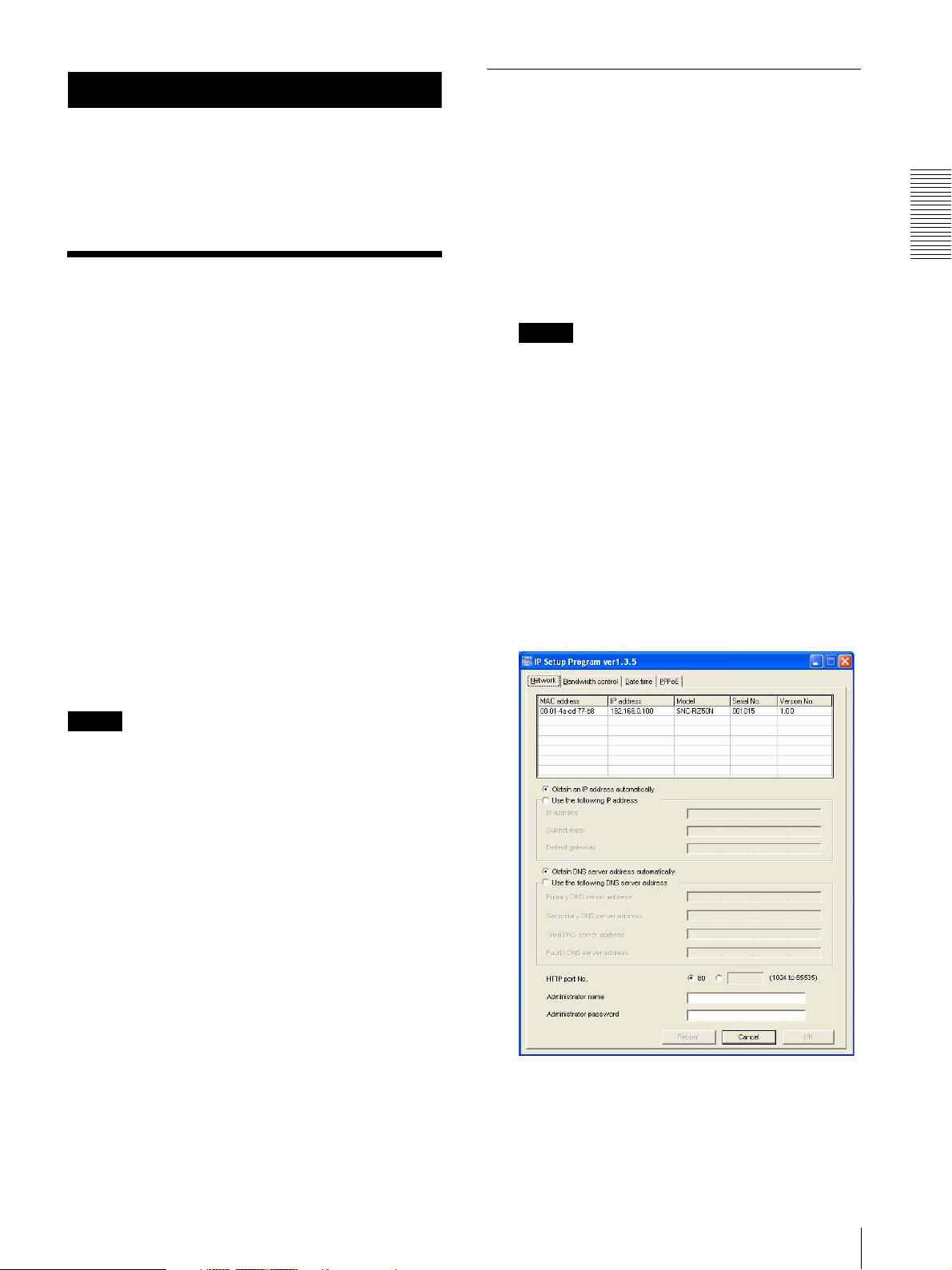
5
Start the IP Setup Program.
The program detects the network cameras
connected to the local network and lists them on the
Network tab window.
Preparation
Notes
• The Setup Program may not operate correctly if you
use a personal firewall or antivirus software in your
computer. In that case, disable the software or assign
an IP address to the camera using another method. For
example, see “Assigning the IP Address to the Camera
Using ARP Commands” on page 84.
• It you are using Windows XP Service Pack 2, disable
the Windows Firewall function. Otherwise the IP
Setup Program will not operate correctly.
To disable Windows Firewall, operate as follows:
1
Open Windows Firewall from Control Panel.
With the category display, you can find Windows
Firewall in Security Center.
2
Select Off, and click OK.
Assigning the IP Address to the Camera
9
Page 10
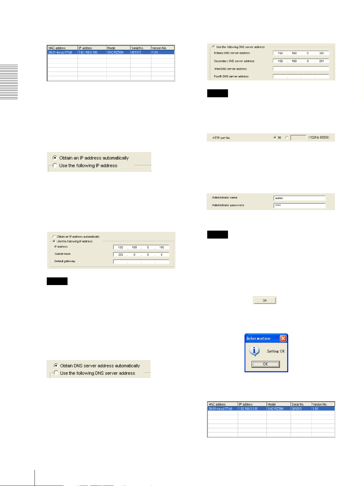
6
Click on the camera in the list to which you want to
assign a new IP address.
Secondary DNS server address in the relevant
boxes.
Preparation
The network settings for the selected camera are
displayed.
7
Set the IP address.
To obtain the IP address automatically from a
DHCP server:
Select Obtain an IP address automatically.
The IP address, Subnet mask and Default gateway
are assigned automatically.
To specify the IP address manually:
Select Use the following IP address, and type the
IP address, Subnet mask and Default gateway in the
relevant boxes.
Note
The Third DNS server address and Fourth DNS
server address are invalid for this camera.
9
Set the HTTP port No.
Normally, select 80 for the HTTP port No. To use
another port number, type the port number between
1024 and 65535 in the text box.
10
Type the Administrator name and Administrator
password.
The factory settings of both items are “admin.”
Note
You cannot change the Administrator name and
Administrator password in this step. To change
these items, see “Setting the User — User Menu”
on page 45.
Note
When you select Obtain an IP address
automatically, make sure that the DHCP server is
operating on the network.
8
Set the DNS server address.
To obtain the DNS server addresses
automatically:
Select Obtain DNS server address automatically.
To specify the DNS server addresses manually:
Select Use the following DNS server address, and
type the Primary DNS server address and
11
Confirm that all items are correctly set, then click
OK.
If “Setting OK” is displayed, the IP address is
correctly assigned.
12
To access the camera directly, double-click the
camera name in the list.
10
Assigning the IP Address to the Camera
Page 11
Tip
The factory setting of the camera network is as
follows.
IP address: 192.168.0.100
Subnet mask: 255.0.0.0
Wireless LAN setting
Type: Adhoc
SSID: snc-rz50
Channel: 11 ch
WEP: Nothing
IP address: 10.0.0.100
Subnet mask: 255.0.0.0
The welcome page of the network camera is
displayed on the web browser.
Accessing the Camera
Using the Web Browser
After the IP address has been assigned to the camera,
check that you can actually access the camera using the
Web browser installed on your computer.
Use Internet Explorer as the Web browser.
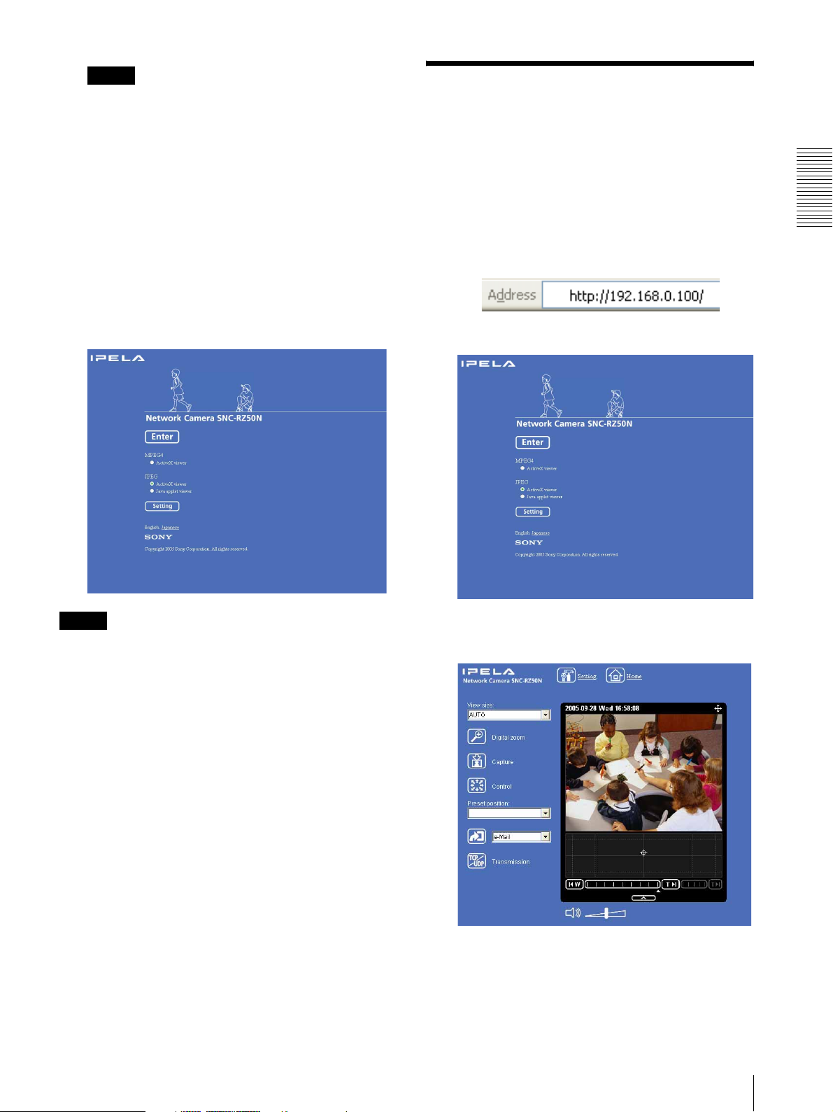
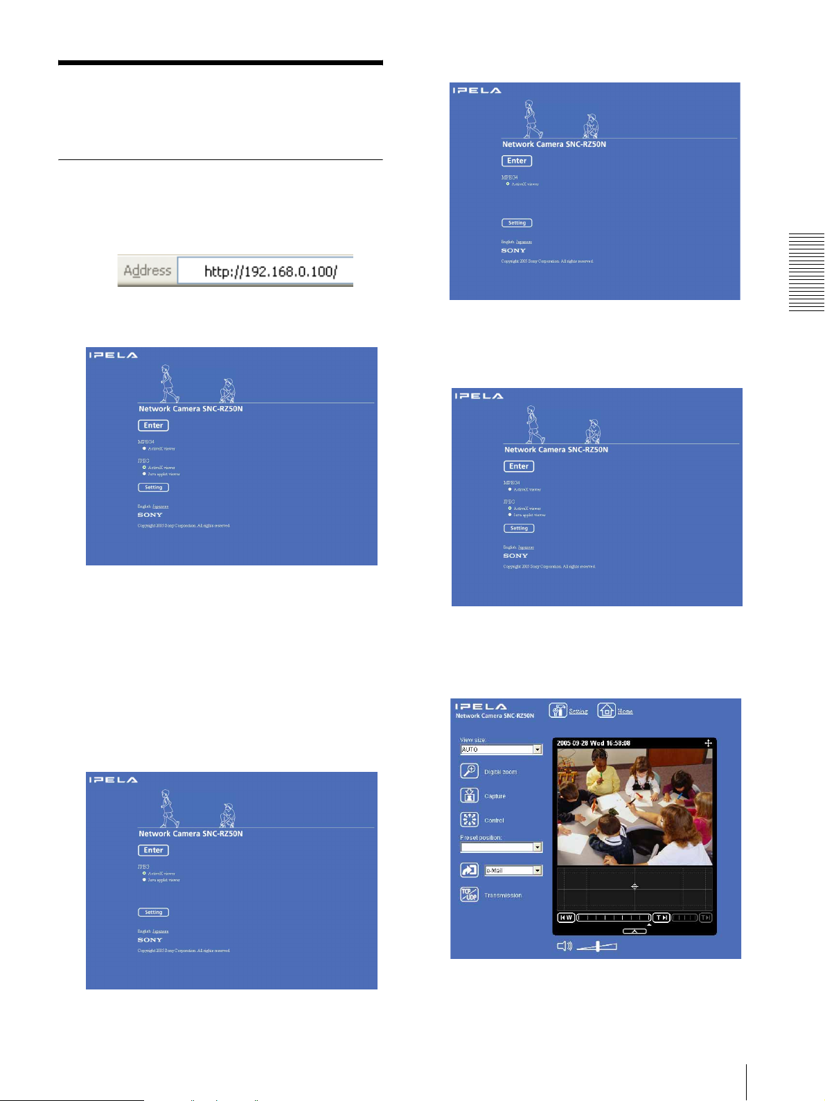
1
Start the Web browser on the computer and type the
IP address of the camera in the URL box.
The welcome page is displayed.
Preparation
Note
If the IP address is not set correctly, the welcome page
does not appear after step 12. In that case, try to set the
IP address again.
2
Click Enter.
The main viewer is displayed.
If the main viewer is displayed correctly, accessing
the camera is confirmed.
Accessing the Camera Using the Web Browser
11
Page 12
Preparation
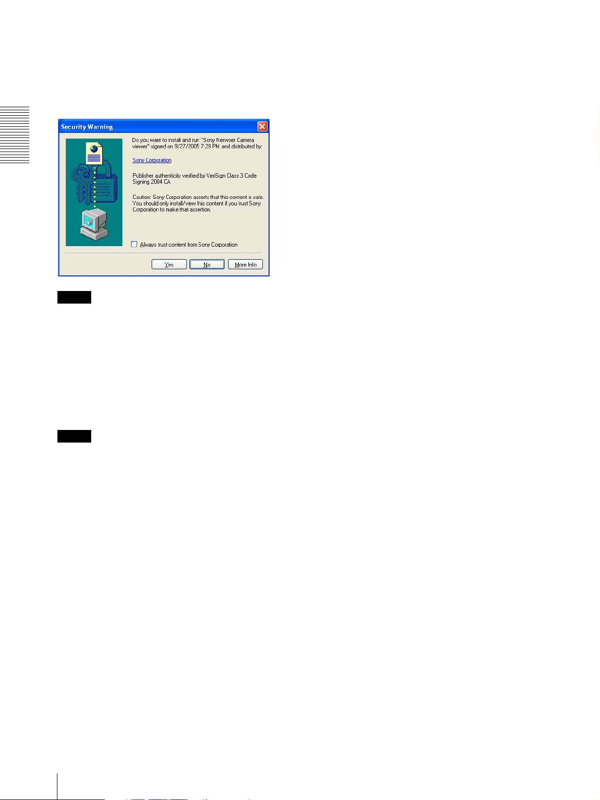
When the main viewer of the camera is
displayed for the first time
When you click Enter, “Security Warning” is displayed.
When you click Ye s, ActiveX control is installed and the
main viewer is displayed.
Notes
• If Automatic configuration is enabled in the Local
Area Network (LAN) Settings of Internet Explorer,
the image may not be displayed. In that case, disable
Automatic configuration and set the Proxy server
manually. For the setting of the Proxy server, consult
your network administrator.
• When you install ActiveX viewer on Windows 2000
or Windows XP, you should be logged in to the
computer as Administrator.
When using antivirus software, etc. on
the computer
• When you use antivirus software, security software,
personal firewall or pop-up blocker on your computer,
the camera performance may be reduced, for example,
the frame rate for displaying the image may be lower.
• The Web page displayed when you log in to the
camera uses JavaScript. The display of the Web page
may be affected if you use antivirus software or other
software described above on your computer.
Tip
Every page of this software is optimized as display
character size Medium for Internet Explorer.
To display the welcome page and the
main viewer correctly
To operate the welcome page and the main viewer
correctly, set the security level of the Internet Explorer
to Medium or lower, as follows:
1
Select Too ls from the menu bar for Internet
Explorer, then select Internet Options and click
the Security tab.
2
Click the Internet icon (when using the camera via
the Internet) or Local intranet icon (when using
the camera via a local network).
3
Set the slider to Medium or lower. (If the slider is
not displayed, click Default Level.)
12
Accessing the Camera Using the Web Browser
Page 13

Basic Configuration by
the Administrator
You can monitor the camera image by logging in with
the initial conditions set for this network camera. You
can also set various functions according to the installing
position, network conditions or purpose of the camera.
We recommend you configure the following items
before monitoring images from the camera.
Setting contents Setting menu
Flip the image according to the installation position (desk top or ceiling). E. flip (page 36)
Set the format of the image sent from the camera. Video codec Tab (page 39)
Preparation
Select the white balance mode according to the installing position (indoor or
outdoor).
Select the brightness of the image sent from the camera. Exposure mode (page 37)
Select the quality of the image sent from the camera. Video codec Tab (page 39)
Select the view size of the image. View size (page 18)
Select whether the audio from the external microphone is sent or not. Microphone (page 36)
Synchronize the date and time of the camera with those of the computer. Date & time Tab (page 33)
Make the setting for sending the monitor image attached to an e-mail. e-Mail (SMTP) Menu (page 50)
Set the user access right for the camera. User Menu (page 45)
Set a place to be watched beforehand. Preset position Menu (page 47)
Prepare a panorama image. Creating a Panorama Image (page 80)
White balance (page 37)
Brightness (page 38)
Basic Configuration by the Administrator
13
Page 14

Operating the Camera
The Operating the Camera section explains how to
monitor the image from the camera using your Web
browser. Use Internet Explorer as the Web browser.
The functions of the camera should be set by the
Administrator. For the setting of the camera, see
“Administrating the Camera” on page 29.
Administrator and User
This network camera identifies the people who log in as
the Administrator or User.
The Administrator can use all the functions of this
network camera including camera setting. The User can
use the functions for monitoring the image and audio
from the camera, and controlling the camera. The
Viewer mode setting is used to restrict the user's access
rights. There are five types of users.
Each type of user can use the corresponding functions
below.
Operating the Camera
Function Administrator
Monitor a live image z zzzzz
View the date and time z zzzzz
Control the frame rate (Available in JPEG mode only) zz––––
Control the image view size z zzzz –
Zoom an image using the digital zoom z zzzz –
Save a still image in the computer z zzzz –
Send an image file to the FTP server zz––––
Send an image attached to an e-mail zz––––
Record an image in the memory zz––––
Control the alarm output of the I/O port on the camera zz––––
Switch the Day/Night function mode zz––––
Play an audio file (Voice alert) zz––––
Switch the TCP/UDP transmission mode (Available in
MPEG4 mode only)
Call the Preset position z zzz ––
Perform the pan/tilt/zoom operation zzz–––
Receive the audio z zzzzz
Control the setting menu z –––––
z Usable function
2)
z
Full Pan/Tilt Preset
2)
z
––––
User
Light View
position
1)
– Not usable function
1) This function is usable with the Java applet viewer.
2) This function is not usable with the Java applet
viewer.
The access rights of the administrator and the user can
be set in “Setting the User — User Menu” of the
Administrator menu on page 45.
14
Administrator and User
Page 15
Logging in to Homepage
— Welcome Page
Logging in as a user
1
Start the web browser on your computer and type
the IP address of the camera you want to monitor.
When MPEG4 is selected
The welcome page of Network Camera is
displayed.
2
Select the viewer.
The usable codecs and viewers are displayed
depending on the Mode setting in the Video Codec
Tab in the Camera menu (page 39).
When Mode is set to Single codec
You can monitor the image of the selected video
codec (JPEG or MPEG4). For JPEG, you can
select Java applet viewer.
When Mode is set to Dual codec
You can monitor JPEG and MPEG4. For JPEG,
you can select Java applet viewer.
3
Click Enter.
The main viewer appears.
With the ActiveX viewer (MPEG4)
Operating the Camera
When JPEG is selected
Logging in to Homepage — Welcome Page
15
Page 16
With the Java applet viewer
Operating the Camera
Control the camera from the main viewer.
Note
If the welcome page does not start correctly, the security
level of the Internet Explorer may be set to higher than
Medium. See “To display the welcome page and the
main viewer correctly” on page 12 and check the
security level.
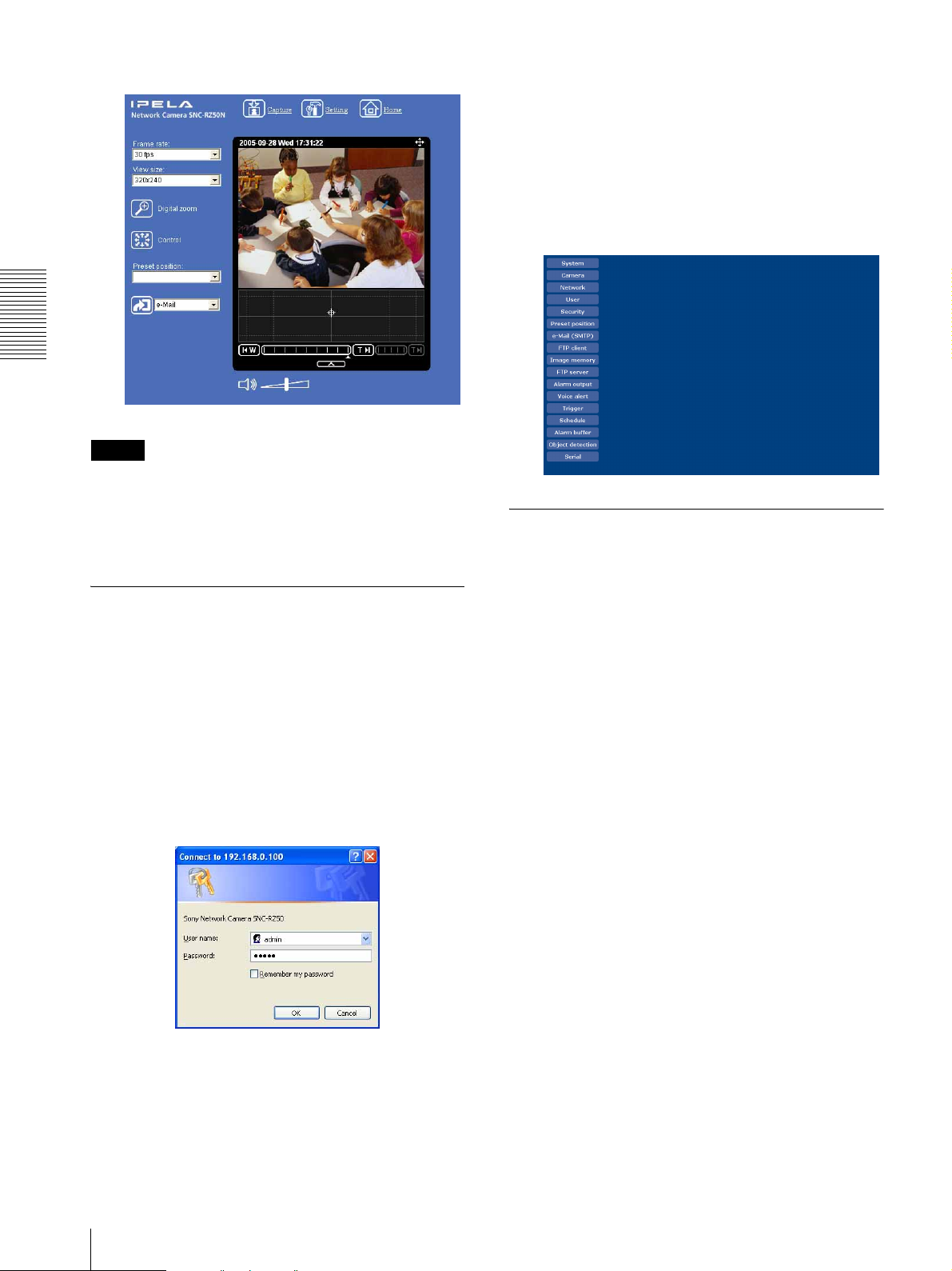
3
Enter the user name and password for
Administrator, then click OK.
The user name “admin” and the password “admin”
are set at the factory for the Administrator. You can
change them using the User menu of the
Administrator menu (see page 45).
The Administrator menu appears in other window.
About viewers
You can use the following viewers.
Displaying the Administrator menu
directly
When the administrator sets the camera functions, the
Administrator menu can be opened directly from the
welcome page.
1
Select the viewer language on the welcome page.
Click English or Japanese at the bottom of the
welcome page.
2
Click Setting on the welcome page.
The following dialog appears.
ActiveX viewer
This viewer can monitor the camera image in either the
JPEG or MPEG4 video codec.
You must install this viewer when you access the main
viewer for the first time.
When you display the main viewer of the
camera for the first time
When you log in the network camera using ActiveX
viewer for the first time (by clicking Enter to enter the
main viewer), the Security Warning appears. Click Ye s
and install ActiveX Control. You can use all the
functions of the viewer with ActiveX Control.
16
Logging in to Homepage — Welcome Page
Page 17
Java applet viewer
You can select this viewer when the camera image is in
JPEG. The frame rate is lower than the ActiveX viewer.
The Java applet viewer operates only when Java is
installed and Java (Sun) is enabled. If it does not operate
correctly, check whether the specified Java version has
been installed successfully and Java (Sun) is enabled.
To check the Java version
Select Tools from the menu bar of Internet Explorer,
then select Internet Options and click the Advanced
mode tab. Check whether the version of Java displayed
for Java (Sun) is one of the versions specified below. If
Java (Sun) is not displayed, it means that Java is not
installed. You need to install Java.
Java Plug-in Ver. 1.5.0_04, Ver. 1.5.0_05
To enable Java Plug-in
Check “Use Java 2 v1.5.0_xx for <applet> (requires
restart)” in “Java (Sun)”.
To install Java Plug-in
Download Java 2 Runtime Environment, Standard
Edition (JRE) from the website of Sun Microsystems,
Inc., and install it by following the instructions on the
installer.
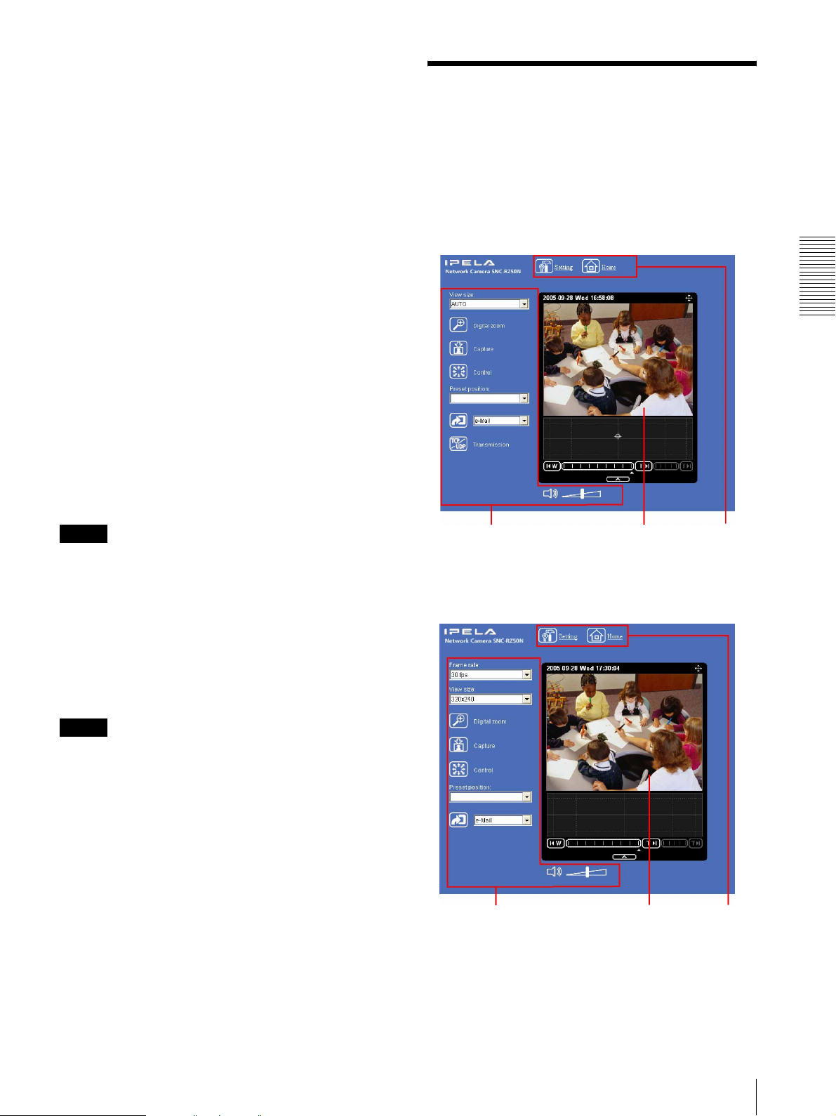
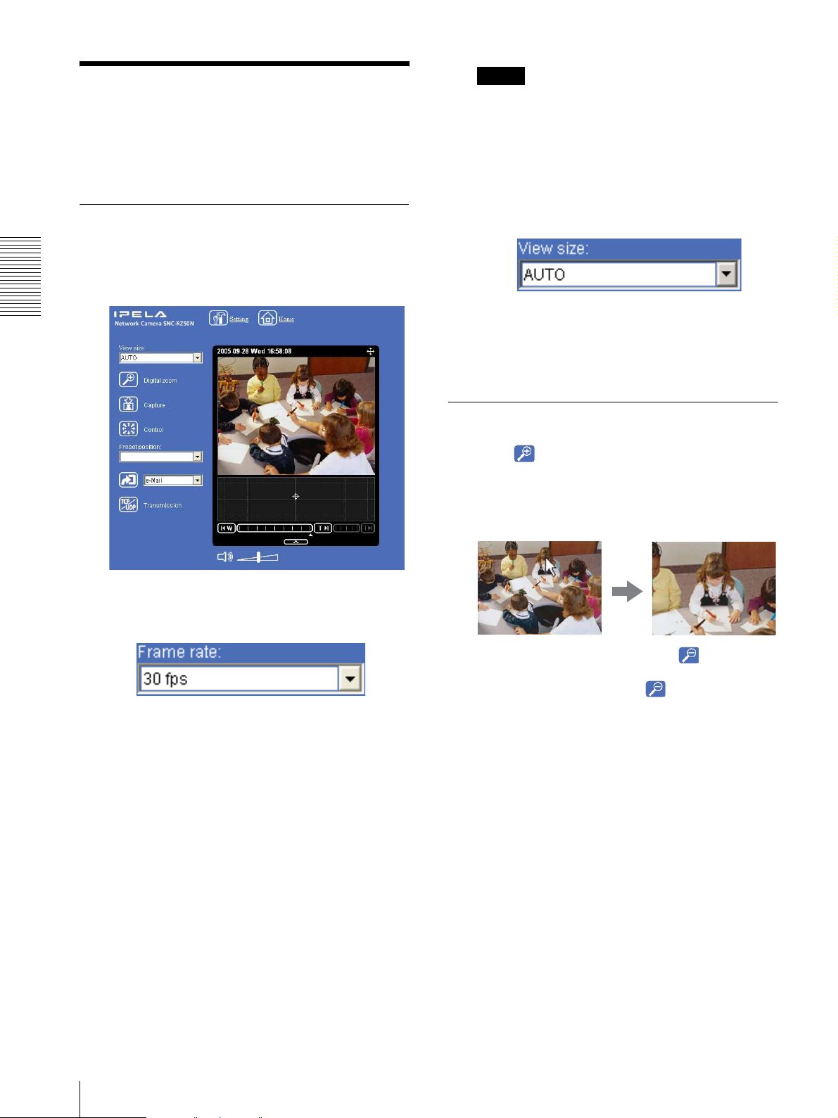
Configuration of Main
Viewer
This section explains the functions of the parts and
controls of the main viewer. For a detailed explanation
on each part or control, see the specified pages.
Main viewer
With the MPEG4 image
Operating the Camera
Notes
• If Automatic configuration is enabled in the Local
Area Network (LAN) Settings of Internet Explorer,
the camera image may not be displayed. In that case,
disable Automatic configuration and set the Proxy
server manually. For the setting of the Proxy server,
consult your network administrator.
• When you install ActiveX viewer on Windows 2000
or Windows XP, you should be logged in to the
computer as the Administrator.
Tip
Every page of this software is optimized for display
character size Medium for Internet Explorer.
Camera control
section
With the JPEG image
Camera control
section
Monitor image
section
Monitor image
section
Main menu
Main menu
Configuration of Main Viewer
17
Page 18
Main menu
Setting
Click to display the Administrator menu. (page 29)
You can operate this function only when logging in as
the administrator.
Preset position
(Displayed only when one or more preset positions are
stored in memory.)
Home
Displays the welcome page.
Camera control section
Operating the Camera
Frame rate
Select the Preset position name from the drop-down
list. The camera will move to the preset position that
you have stored in memory using the Preset position
menu.
Note
If you use Windows 2000, the preset position name of
Japanese may be shown in unreadable characters.
Control panel
(Displayed only when the camera image is in JPEG.)
Selects the frame rate to transmit images. (page 20)
Click to display the following control panel.
View size
Selects the view size to be displayed. (page 20)
Digital zoom
Click to change the size of the digital zoom. (page 20)
Capture
(Displayed in the main menu when the Java applet
viewer is used.)
Click to capture a still image shot by the camera and to
store it in the computer. (page 21)
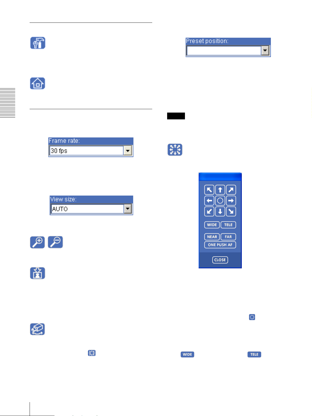
Control
Click to operate the camera using the pan, tilt and zoom
functions.
When you click this icon, appears and enables you
to control pan, tilt and zoom functions from the main
viewer. (page 22)
You can control pan, tilt, zoom, and focus of the camera.
(page 22)
Pan/Tilt control
Click the arrow button of the direction in which you
want to move the camera. Keep it pressed to move the
camera continuously.
To return to the home position, click .
You can select the operation mode of the 8-direction
arrow buttons for panning and tilting in PTZ mode of
the System menu.
Zoom control
Press to zoom out, and press to zoom in.
Zooming continues while the button remains pressed.
18
Configuration of Main Viewer
Page 19
Focus control
To focus on a nearby object, press . To focus on a
distant object, press .
By pressing , the focus is set to the
optimum position.
Note
To control the focus manually, set Focus mode of the
Camera menu to Manual. (page 36)
Note
If does not appear when the Java applet
viewer is used, Audio codec may not be set to G.711 (64
kbps) (page 36), Codec in the Alarm buffer menu is set
to MPEG4, or Java may not be installed correctly.
To check if Java is installed correctly, refer to “Java
applet viewer” of “About viewers” on page 16.
Trigg er
(Displayed only when the camera Viewer mode
(page 46) is set to Full and one or more triggers are
enabled in the Trigger menu (page 61).)
Select the function you want to use from the drop-down
list and click . The selected function is activated.
The selectable functions are as follows:
– send the still images to an FTP server (page 25)
– send the still images attached to an e-mail (page 25)
– record the still images on a CF memory card (not
supplied) or an ATA memory card (not supplied)
(page 25)
– switch the alarm output on/off (page 26)
– switch the Day/Night function on/off (page 26)
– play the audio file stored in the camera (page 27)
Transmission (TCP/UDP
transmission mode)
(Displayed only when the camera image is in MPEG4
and the ActiveX viewer is used.)
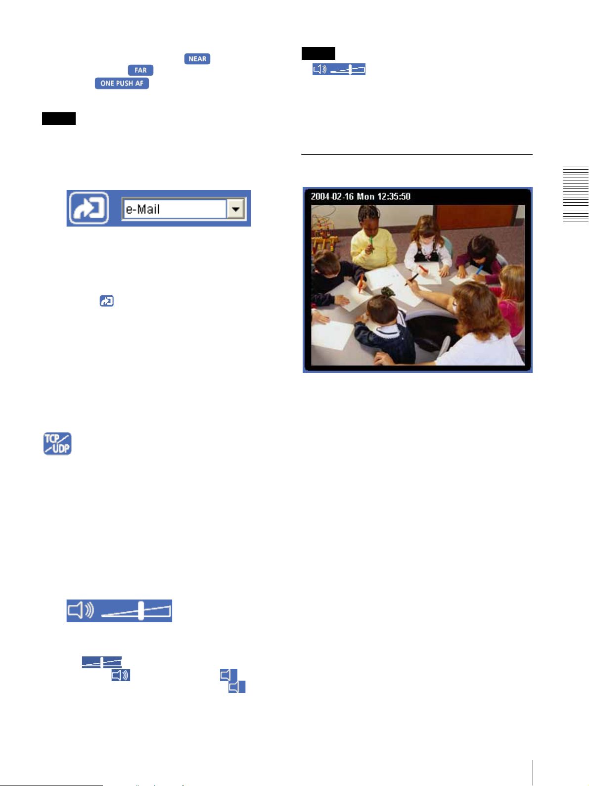
Monitor image
Operating the Camera
The image shot by the camera is shown here. The date
and time is displayed at the top of the window.
Each click switches the transmission mode of the video/
audio data between TCP mode, UDP (Unicast) mode,
and UDP (Multicast) mode. (page 27)
The last selected mode is saved in the computer, and will
stay selected for the next startup.
Volume
(Displayed when Microphone (page 36) is set to On.)
Drag the bar to adjust the volume.
When you click , the icon changes to and the
audio output stops. To output the audio, click again.
Configuration of Main Viewer
19
Page 20
Controlling the Monitor
Image
You can monitor the camera image on the monitor
window of the main viewer.
Monitoring the camera image
1
Log in to the homepage to display the main viewer.
To log in, see “Logging in as a user” on page 15.
Note
The selected value indicate the maximum number
of frame rate that can be transmitted.
The number of frames actually transmitted may
vary depending on network environments and
camera settings (image size and image quality
settings).
3
Select the view size.
Operating the Camera
Click View size list box to select the view size from
Aut o, 640 × 480, 320 × 240, or 160 × 120.
Aut o is determined by the image size specified in
the Camera menu (page 36)
Zooming in the monitor image
1
Click .
2
Click the point you want to zoom in.
The image is magnified by about 1.5 times with the
clicked point at the center.
2
Select the frame rate (only when the camera image
is in JPEG).
The digital zoom icon changes to .
3
To cancel zooming in, click .
Click the Frame rate list box to select the frame
rate for transmitting the image. Selectable frame
rates are as follows.
SNC-RZ50N
1, 2, 3, 4, 5, 6, 8, 10, 15, 20, 25, 30 fps
SNC-RZ50P
1, 2, 3, 4, 5, 6, 8, 12, 16, 20, 25 fps
The number refers to the frame number transmitted
per second.
For example, if you select 30 fps for SNC-RZ50N,
the image is sent at the maximum speed of the
connected line (30 fps maximum).
20
Controlling the Monitor Image
Page 21
Capturing a Monitor
Saving the captured image
Image
You can capture an image being monitored as a still
image and save it in the computer.
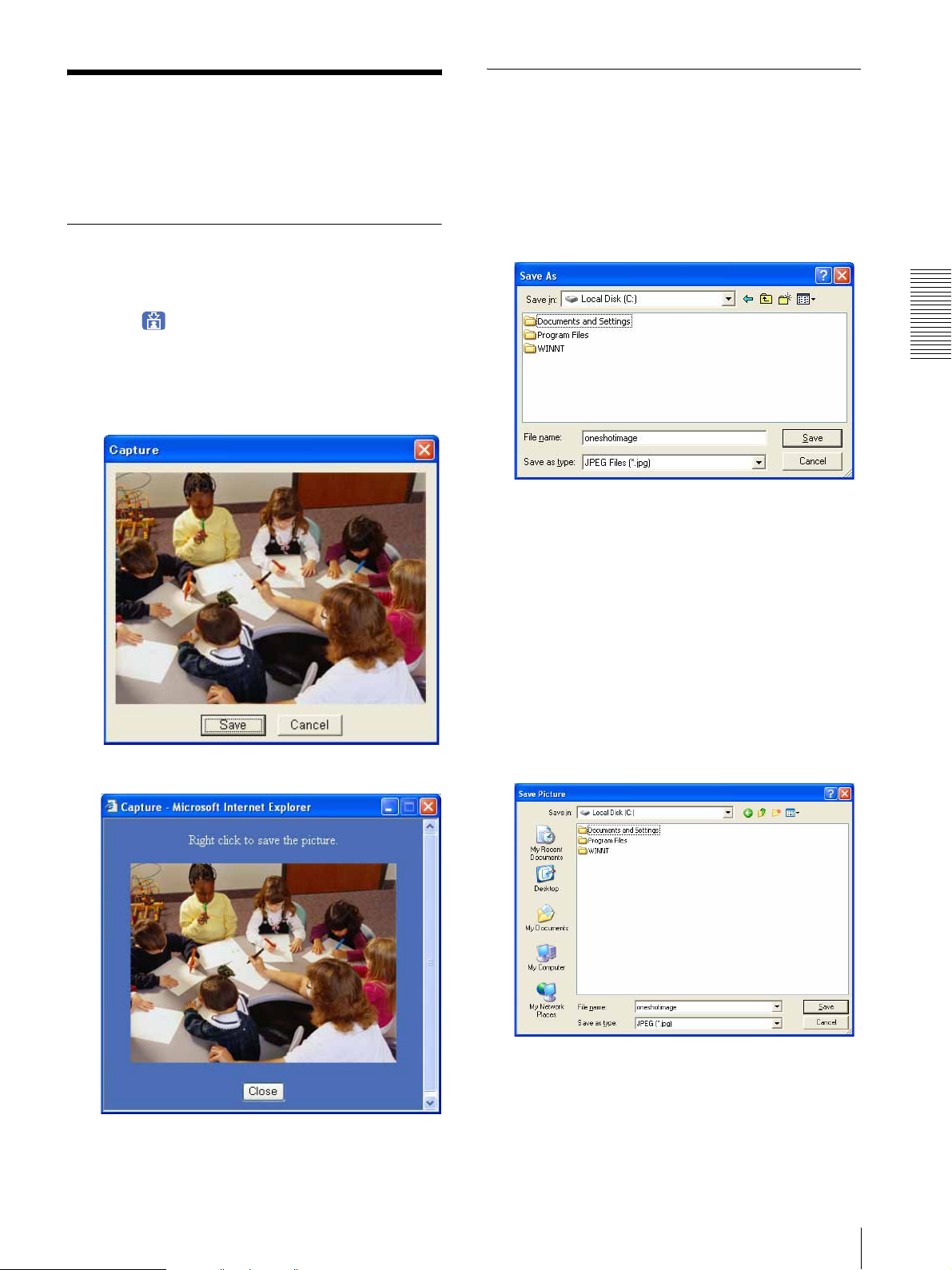
Capturing a monitor image
1
Display the camera image in the monitor window.
2
Click .
The still image of the moment you click is captured,
and this still image is displayed in the capture
window.
With the ActiveX viewer
With the ActiveX viewer
1
Capture the monitor image.
2
Click Save.
The Save As dialog appears.
3
Select JPEG Files or Windows Bitmap Files as
Save as type.
4
Type the File name and specify Save in, then click
Save.
Operating the Camera
With the Java applet viewer
With the Java applet viewer
1
Capture the monitor image.
2
Right-click the mouse to display the menu and
select Save with a new name.
The Save Picture dialog appears.
3
Select JPEG or Bitmap as Save as type.
3
To close the capture window, click Cancel or
Close.
4
Type in File name and specify Save in, then click
Save.
Capturing a Monitor Image
21
Page 22
Pan/Tilt control
Operating the Camera
You can operate the camera from the main viewer.
When you click , the display switches to . Next,
and Preset position list box are displayed on the
upper right of the window.
When is displayed in white on the upper right of the
window, you can use the Pan/Tilt control function. If you
execute the digital zoom when you can control Pan/Tilt,
turns gray and you can no longer control the camera
in the monitor window or in the panorama window, nor
can you control zoom in the zoom bar.
When you cancel the digital zoom, returns to white.
Operating the Camera
Notes
•The Preset position list box is not displayed when no
preset position is memorized.
•When Exclusive control mode of the System menu is
set to On and you click , the remaining time that
you are authorized to operate the camera is displayed.
If you cannot get the control, the icon switches to
and the waiting time is displayed.
Click the arrow button of the direction in which you
want to move the camera. Keep it pressed to move the
camera continuously.
To return to the home position, click .
Zoom control
Click to zoom out, and click to zoom in.
Zooming continues while the button remains pressed.
Focus control
To focus on a nearby object, click . To focus on a
distant object, click .
By clicking , the focus is set to the
optimum position.
Note
To control the focus manually, set Focus mode of the
Camera menu to Manual. (page 36)
Panning and tilting by clicking the
monitor image
Click on the monitor image, and the camera moves so
that the clicked portion is positioned at the center of the
display.
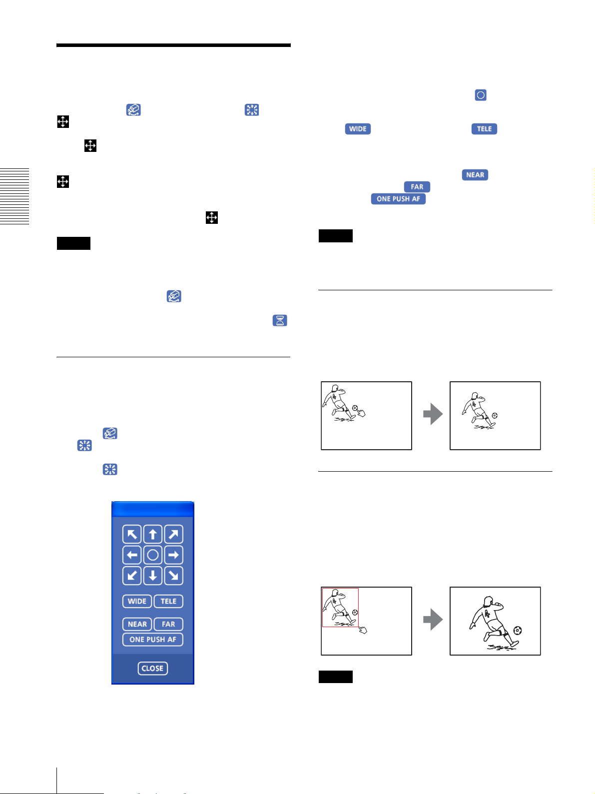
Controlling via the control panel
You can operate the camera direction, zoom, and focus
by using the control panel for the monitor image
currently displayed.
1
Click .
is displayed.
2
Click .
The control panel is displayed.
Panning, tilting and zooming by
specifying the area
Click and hold the left button of the mouse on the
monitor image, and drag the mouse diagonally to draw a
red frame around the portion you want to enlarge. The
camera moves so that framed portion is positioned at the
center of the display and is zoomed in.
3
22
Operating the Camera
Control each function using the displayed control
panel.
Notes
• When Zoom mode in the Camera menu is set to Full
(see page 36), zooming of the specified area stops at
the TELE end of the optical zoom. If you want to
Page 23
zoom in further using the digital zoom, specify the
area again.
• When the specified area is zoomed in, the center may
be shifted. In this case, click the point you want to
move to the center.
Zooming an image by the camera
zoom bar
When you have the authorization to control this
function, the zoom bar is displayed below the window.
You can specify a location to be zoomed by clicking the
zoom bar.
The zoom bar is either displayed or turned off by
clicking below the image frame.
Optical WIDE end icon: Click to move the zoom
to optical WIDE end (same magnification).
Optical TELE end icon: Click to move the zoom
to optical TELE end (26 × magnification).
Digital TELE end icon: Click to move the zoom to
digital TELE end (312 × magnification)
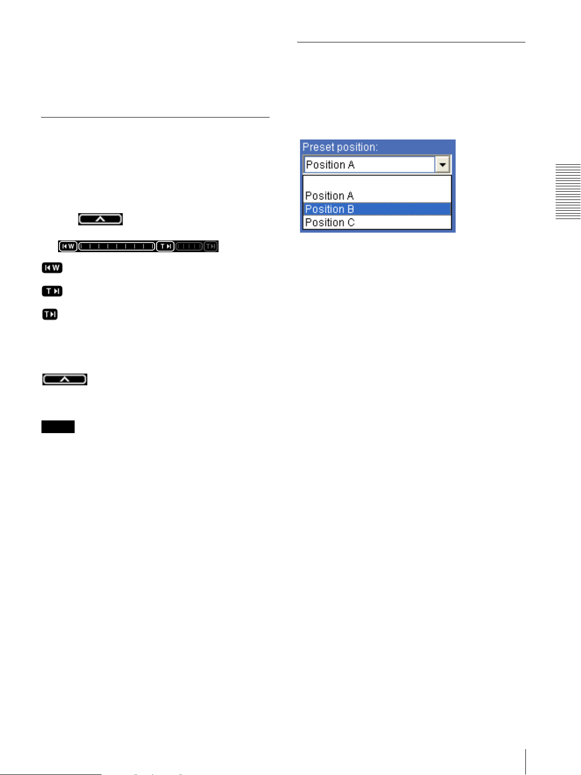
Moving the camera to a preset
position
Select a preset position name from the Preset position
drop-down list. The camera will move to the preset
position that you have stored in memory using the Preset
position menu (page 47).
Operating the Camera
Turning off the zoom bar
When you are not going to use the zoom bar, click
under the panorama window to turn off the
panorama window. Click it again to turn off the zoom
bar.
Note
The zoom bar of the digital area is not displayed when
Zoom mode of the Camera menu is not set to Full.
Operating the Camera
23
Page 24
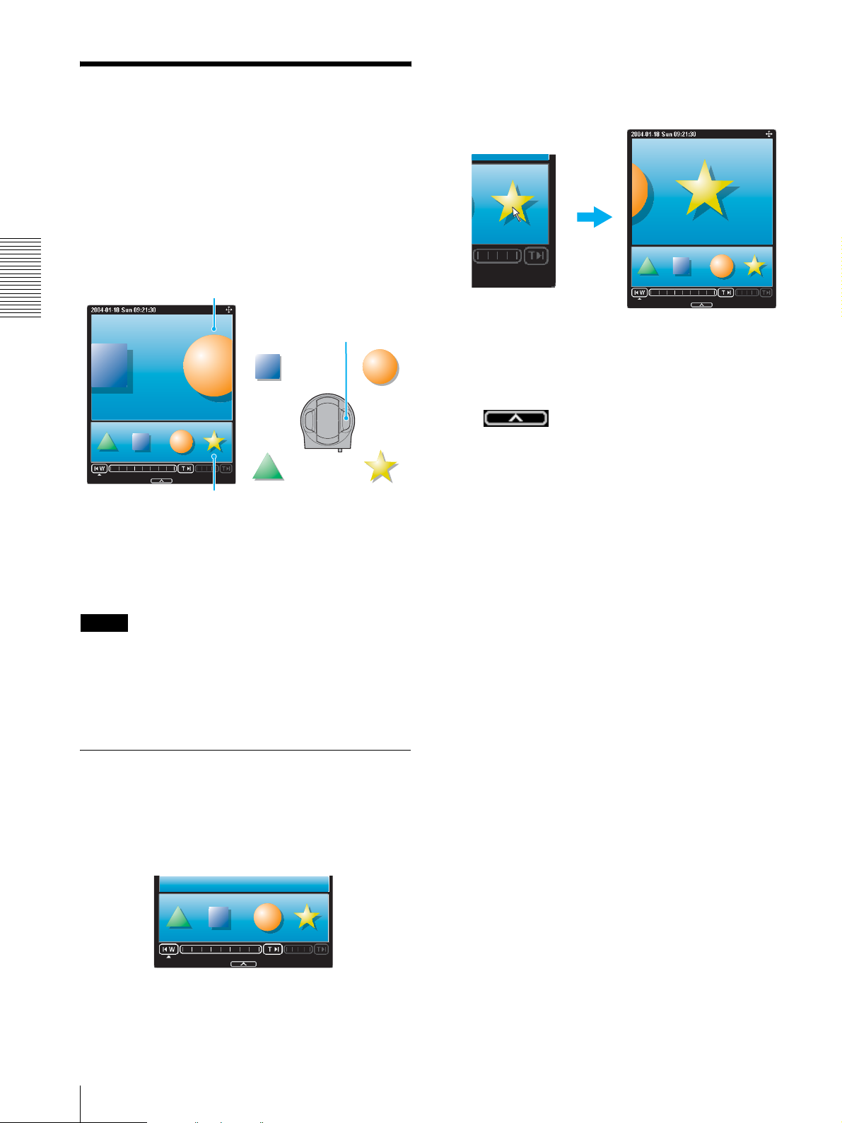
Controlling the Camera
on a Panorama Image
When you have the authorization to control the camera,
the panorama window is displayed under the monitor
window.
In the panorama window, a 360° view around the camera
is displayed as a panorama image. When you click on
the displayed panorama image, the camera faces the
clicked area.
Monitor window
The camera is moved to face toward the clicked
point, and the present image at the point is
displayed in the normal camera window.
Operating the Camera
SNC-RZ50N/RZ50P
Click the point you
want to watch.
The present situation is
displayed at the clicked point.
To turn off the panorama window
When you are not going to use the panorama image,
click under the panorama window to turn off
the panorama window.
Panorama window
To create the panorama image
Create the panorama image with the supplied SNC
panorama creator. Refer to page 80 for details.
Tip
The panorama image is a still picture converted from the
image taken when you were going to create it with the
SNC panorama creator. When the camera is moved or
when the layout around the camera is changed, you
should create the panorama image again.
Facing the camera toward a
specified point
1
Create a panorama image with the SNC panorama
creator and display it.
2
Click the point you want to watch on the panorama
image.
24
Controlling the Camera on a Panorama Image
Page 25
Sending an Image File
Recording a Still Image
You can send a captured still image by attaching it to an
e-mail, or to the FTP server.
To use this function, you need to make e-Mail (SMTP)
or FTP client active and set the address properly in the
Trigger menu of the Administrator menu (page 62).
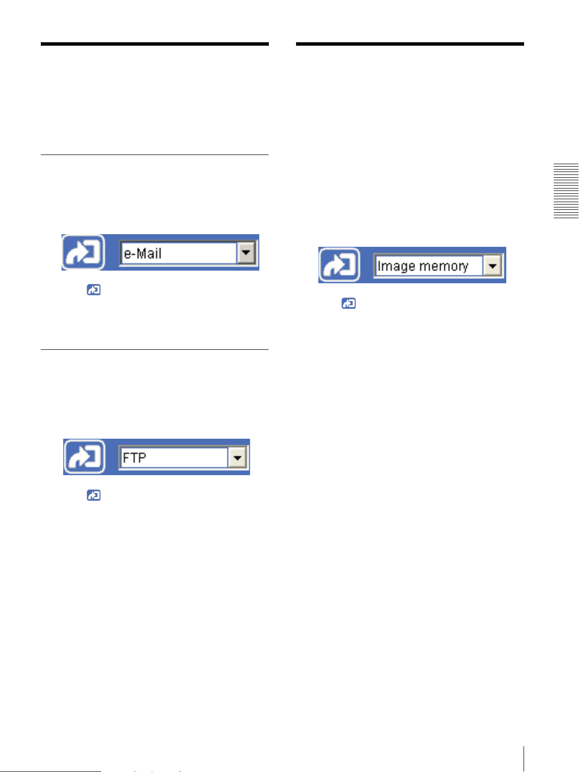
Sending a monitor image via e-mail
1
Display the image on the monitor window.
2
Select e-Mail from the trigger drop-down list.
3
Click .
The still image of the moment you click is captured,
and your e-mail with the image file attached is sent
to the specified mail address.
Sending a monitor image to an FTP
in the Memory
You can capture a camera image as a still picture and
record on in a CF memory card (not supplied) or an ATA
memory card (not supplied).
To use this function, you need to insert the CF memory
card or ATA memory card into the camera, make Image
memory active and set the details in the Trigger menu of
the Administrator menu (page 62).
1
Display the image on the monitor window.
2
Select Image memory from the trigger drop-down
list.
3
Click .
The still image of the moment you click is captured,
and the image file is recorded on the CF memory
card or ATA memory card.
Operating the Camera
server
1
Display the image on the monitor window.
2
Select FTP from the trigger drop-down list.
3
Click .
The still image of the moment you click is captured,
and the image file is sent to the FTP server.
Sending an Image File / Recording a Still Image in the Memory
25
Page 26
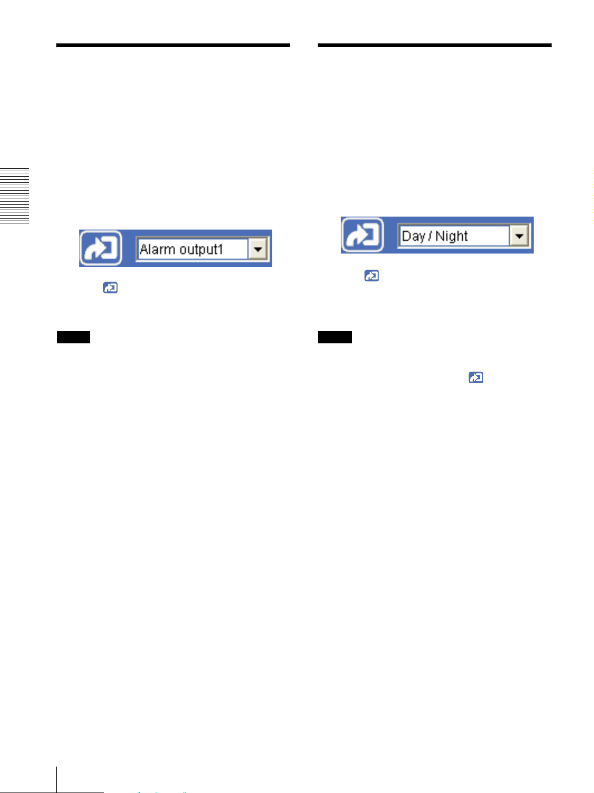
Controlling Alarm
Controlling Day/Night
Output 1, 2
You can control On (short-circuit) and Off (open) of
Alarm Output 1, 2.
To use this function, you need to make Alarm output 1
or Alarm output 2 active in the Trigger menu of the
Administrator menu (page 62).
1
Display the image on the monitor window.
2
Select Alarm output1 or Alarm output2 from the
trigger drop-down list.
Operating the Camera
3
Click .
Each click switches the alarm output alternately
between On (short-circuit) and Off (open).
Tip
For the connection of peripheral devices to the alarm
output of the I/O port, see the supplied Installation
Manual.
Function
You can control the Day/Night function On (night mode)
and Off (day mode).
To use this function, you need to make Day/Night active
in the Trigger menu of the Administrator menu
(page 62).
1
Display the image on the monitor window.
2
Select Day/Night from the trigger drop-down list.
3
Click .
Each click switches the Day/Night function
alternately between On (night mode) and Off (day
mode).
Note
If Day/Night mode in the Trigger-Day/Night menu
(page 62) is set to Disable or Auto, you cannot control
the Day/Night function by clicking .
26
Controlling Alarm Output 1, 2 / Controlling Day/Night Function
Page 27
Playing the Audio File
Switching TCP/UDP
Stored in the Camera
You can play the audio file stored in the camera using the
SNC audio upload tool.
To use this function, you need to make Voice alert
active in the Trigger menu of the Administrator menu
(page 63).
1
Display the image on the monitor window.
2
Select Voice alert from the trigger drop-down list.
3
Click .
Playback of the audio file starts and the playback
sound is output from the speaker connected to the
camera.
Transmission Mode
You can select TCP or UDP as the communication port
for the video/audio data.
This function can be used when Mode (video codec
mode) (page 39) is set to MPEG4 and the ActiveX
viewer is used.
Notes
• The function may not operate correctly when you use
personal firewall software or antivirus software on
your computer. In that case, disable the software or
select the TCP mode.
• If you are using Windows XP Service Pack 2, disable
“Windows Firewall” (see page 9).
1
Open the main viewer.
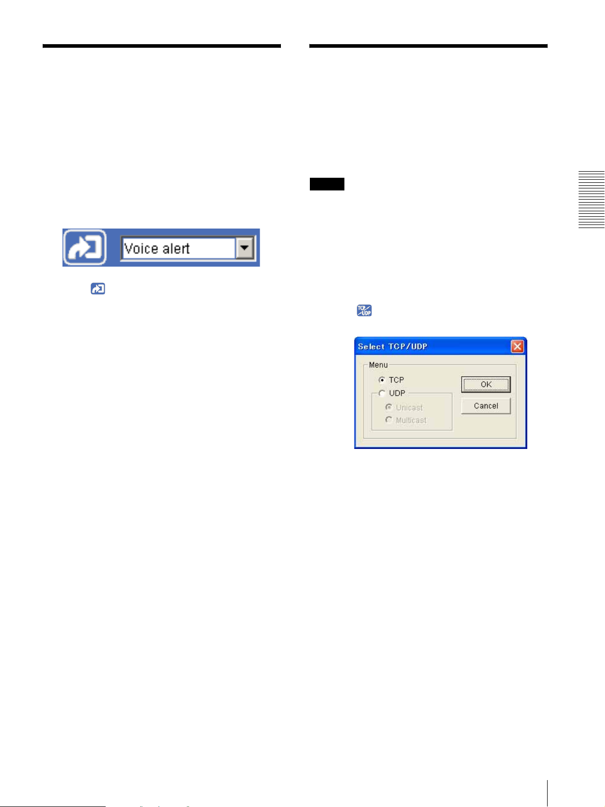
2
Click TCP/UDP Transmission.
The Select TCP/UDP dialog appears.
Operating the Camera
3
Click one of the buttons TCP, UDP (Unicast) or
UDP (Multicast).
TCP: This is normally selected.
When TCP is selected as the communication port,
HTTP communication is adopted for video/audio
communications.
HTTP is the protocol used for reading the usual
Web page.
In an environment capable of reading Web pages,
you can watch or listen to the video/audio by
selecting the TCP port.
UDP (Unicast): When UDP (Unicast) is selected
as the communication port, RTP (Real-time
Transport Protocol) is adopted for video/audio
communications. Since RTP is the protocol for
running video/audio data, the video/audio playback
is smoother than when TCP (HTTP) is selected. If
a firewall is installed between the camera and the
computer, or depending on the network
environment, the video/audio may not play back
Playing the Audio File Stored in the Camera / Switching TCP/UDP Transmission Mode
27
Page 28

properly when UDP (Unicast) is selected. In that
case, select TCP.
UDP (Multicast): This protocol is selectable when
Multicast streaming (page 41) is On. When UDP
(Multicast) is selected as the transmission port,
RTP (Real-time Transport Protocol) and UDP
multicast techniques are adopted for video/audio
transmission. By selecting it, the network
transmission load of the camera can be reduced. If
a router that does not correspond to the multicast or
a firewall is installed between the camera and the
computer, the video/audio may not play back
properly. In that case, select TCP or UDP
(Unicast).
Operating the Camera
4
Click OK to close the dialog.
If you do not change the transmission setting, click
Cancel.
28
Switching TCP/UDP Transmission Mode
Page 29

Administrating the Camera
Basic Operations of
The Administrating the Camera section explains how to
set the functions of the camera by the Administrator.
For the monitoring of the camera image, see “Operating
the Camera” on page 14.
This section explains the basic operations and each
option of the Administrator menu.
Note on the display of menu options
The setting menus of this unit will clearly display only
the setting options that you can currently select. The
grayed out options cannot be selected.
Administrator Menu
You can use the Administrator menu to set all functions
to suit the user's needs.
Click Setting in the welcome page or in the main
viewer to display the Administrator menu.
How to setup the Administrator
menu
1
Log in the homepage to display the welcome page.
You can learn how to log in on page 15 “Logging in
as a user”.
2
Select the viewer language on the welcome page.
Click English or Japanese at the bottom of the
welcome page.
3
Click Setting on the welcome page.
The authentication dialog appears. Enter the user
name and password for Administrator.
The user name “admin” and password “admin” are
set at the factory for the Administrator.
Administrating the Camera
Administrator menu appears.
The following steps also display the Administrator
menu.
1 Click Enter in the welcome page to display the
main viewer.
2 Click in the main viewer.
3 Enter the user name and password for
Administrator.
4
Click the menu name (example: System) on the left
side of the Administrator menu.
The clicked menu appears.
Basic Operations of Administrator Menu
29
Page 30

Example: “System” menu
General notes on menus
• After changing a setting on a menu, wait at least 10
seconds before turning off the power of the camera.
If the power is turned off immediately, the changed
setting may not be stored correctly.
• When the camera settings are changed while watching
the main viewer, some settings cannot be restored. To
reflect the change on the opening main viewer, click
Refresh of the web browser.
Configuration of Administrator menu
5
Select the required tab above the menu, and set each
setting option in the tab.
Example: “Date & time” tab of “System” menu
Administrating the Camera
See pages 32 to 72 for details of the menu tabs and
setting options.
6
After setting, click OK.
The settings you have made become active.
Click Cancel to invalidate the set values and return
to the previous settings.
Buttons common to every menu
The following buttons are displayed on all the menus.
The functions of the buttons are the same on every
menu.
Click this button to validate the settings.
System
Displays the System menu.
(“Configuring the System — System Menu” on page 32)
Camera
Displays the Camera menu for setting the camera image
and audio. (“Setting the Camera Image and Audio —
Camera Menu” on page 36)
Network
Displays the Network menu for setting the network
connection. (“Configuring the Network — Network
Menu” on page 41)
User
Displays the User menu for setting the log in user name
and password. (“Setting the User — User Menu” on
page 45)
Security
Displays the Security menu for specifying a computer
that is allowed to connect to the camera. (“Setting the
Security — Security Menu” on page 46)
Click this button to invalidate the set values and return to
the previous settings.
30
Basic Operations of Administrator Menu
Preset position
Displays the Preset position menu to register a position
you want to save.
“Tour function”, which rotates the registered positions,
is also set here. (“Saving the Camera Position and
Action — Preset position Menu” on page 47)
Page 31

e-Mail (SMTP)
Displays the e-Mail (SMTP) menu for sending an email. (“Sending an Image via E-mail — e-Mail (SMTP)
Menu” on page 50)
FTP client
Displays the FTP client menu for sending an image/
audio file, etc. to an FTP server. (“Sending Images to
FTP Server — FTP client Menu” on page 53)
Image memory
Displays the Image memory menu for recording an
image/audio file, etc. on a CF memory card (not
supplied) or an ATA memory card (not supplied)
inserted into the camera. (“Recording Images in
Memory — Image memory Menu” on page 55)
FTP server
Displays the FTP server menu for setting the FTP server
function of the camera.
(“Downloading Images from the Camera — FTP server
Menu” on page 59)
Alarm output
Displays the Alarm output menu for setting the alarm
out terminal of the camera. (“Setting the Alarm Output
— Alarm output Menu” on page 59)
Object detection
Displays the Object detection menu for the object
detection function built into the camera. (“Setting the
Object Detection Function — Object detection Menu”
on page 65)
Serial
Displays the Serial menu for communications with
external equipment through the external serial terminal.
(“Transmitting with External Equipment Using the
External Serial Terminal — Serial Menu” on page 72)
Administrating the Camera
Voice alert
Displays the Voice alert menu for playing the audio file
stored in the camera in synchronization with alarm
detection by the sensor input or the object detection
function. (“Outputting Audio Linked to Alarm
Detection — Voice alert Menu” on page 60)
Trigger
Displays the Trigger menu for operations when you
click the trigger button in the main viewer. (“Setting the
Operations from the Viewer — Trigger Menu” on page
61)
Schedule
Displays the Schedule menu for the Day/Night function,
Preset position function, e-Mail (SMTP) function, FTP
client function, Image memory function and Alarm out
function, Voice alert function and so on. (“Setting the
Schedule — Schedule Menu” on page 63)
Alarm buffer
Displays the Alarm buffer menu for the buffer that
records the image and audio related to alarm detection.
(“Setting the Alarm Buffer — Alarm buffer Menu” on
page 64)
Basic Operations of Administrator Menu
31
Page 32

Homepage
Configuring the System
Select the homepage to be displayed when you enter the
camera IP address in your browser’s web address box.
— System Menu
Default: Displays the homepage stored in the camera.
When you click System in the Administrator menu, the
System menu appears.
Use this menu to perform the principal settings of the
software.
The System menu has five tabs: System, Date & time,
Initialize, System log and Access log.
System Tab
Administrating the Camera
Custom: Displays your individual homepage.
You can display your favorite homepage stored in the
built-in flash memory, a CF memory card (not
supplied) or an ATA memory card (not supplied).
To store the HTML file of the homepage in the builtin flash memory, use the Custom Homepage Installer
included in the supplied CD-ROM.
To learn how to use of the Custom Homepage
Installer, see page 82.
For the verified cards, contact your authorized Sony
dealer.
To display your individual homepage, perform the
following operation:
1
Select Custom.
2
Type the path of the HTML file using up to 64
characters in the text box on the right of Path.
Title bar name
Type a name of up to 32 characters to be displayed on the
title bar. The characters typed here are displayed on the
title bar of the Web browser.
Welcome text
Type any text of up to 1024 characters in HTML format
to show on the welcome page. Use the <BR> tag for a
line break. (A line break is equivalent to 2 characters.)
Serial number
The serial number of the camera is displayed.
Software version
The software version of this camera is displayed.
3
In Selected memory, select the memory in which
the homepage is stored.
You can select Flash memory, CF memory card
or ATA memory card.
The directory displayed in the text box on the right
of Path changes according to the selected memory.
Tip
Even when you select Custom, the homepage inside the
camera can be displayed by typing the following URL in
the address box of your web browser.
Example: When the IP address of the camera is set to
192.168.0.100
http://192.168.0.100/en/index.html
Exclusive control mode
Controls the authority to operate pan, tilt, zoom and
some other functions of the camera.
On: Only one user has control authority. Set the
operation time for one user in Operation time.
If a user tries to operate a function during operation
by another user, the authority is controlled by the
settings of Operation time and Maximum wait
number.
Off: Multiple users can control pan, tilt and zoom at the
same time. When multiple users control these
functions at the same time, the last operation has
priority.
32
Configuring the System — System Menu
Page 33

Operation time
Sets the time length for a user who has control authority.
The selectable range is from 10 to 600 seconds. This is
effective when Exclusive control mode is On.
Maximum wait number
Sets the number of users who are permitted to wait for
their turn for control authority during operation by one
user. The selectable number is from 0 to 10. This is
effective when Exclusive control mode is On.
Notes
• To use Exclusive control mode, the date and time of
the camera and the connected computer must be set
correctly at first.
• To use Exclusive control mode, do not disable the
web browser Cookie. When it is disabled, this mode
cannot be used.
• When you change the Exclusive control mode
setting, click Refresh on the web browser to reflect
the change when opening the main viewer.
PTZ mode
Select the pan/tilt control mode using the 8-direction
arrow buttons (page 22) and the zoom control mode
using the TELE/WIDE button (page 22).
Select Normal or Step.
Normal: When you click the mouse button, the camera
starts panning, tilting or zooming operation, and the
operation continues while you hold down the
mouse button. To stop the operation, release the
mouse button.
Step: Each time you click the mouse button, the camera
moves (panning, tilting or zooming). If you keep the
mouse button held down for more than 1 second, the
operation mode is temporarily changed to Normal.
When you release the mouse button, the camera
operation stops and the Step mode is restored.
Level
Select the transition level of camera operation by
clicking the mouse button once. This section is effective
when PTZ mode is set to Step.
Pan/Tilt: Select the camera transition level from 1 to 10
by clicking the 8-direction arrow button for panning/
tilting. Selecting 10 provides the maximum
transition level.
Zoom: Select the camera transition level from 1 to 10 by
clicking or for zooming. Selecting 10
provides the maximum transition level.
OK/Cancel
See “Buttons common to every menu” on page 30.
Date & time Tab
Current date & time
Displays the date and time set on the camera.
Note
After you have purchased the camera, be sure to check
the date and time of the camera and set them if
necessary.
PC clock
Displays the date and time set on your computer.
Date & time format
Select the format of date and time to be displayed in the
main viewer from the drop-down list.
You can select the format between yyyy-mm-dd
hh:mm:ss (year-month-day hour:minute:second), mm-
dd-yyyy hh:mm:ss (month-day-year
hour:minute:second), and dd-mm-yyyy hh:mm:ss
(day-month-year hour:minute:second).
Adjust
Select how to set the day and time.
Keep current setting: Select if you do not need to set
the date and time.
Synchronize with PC: Select if you want to
synchronize the camera’s date and time with those of
the computer.
Manual setting: Select if you want to set the camera’s
date and time manually.
Select the year, month, date, hour, minutes and
seconds from each drop-down list.
Synchronize with NTP: Select if you want to
synchronize the camera’s date and time with those of
the time server called NTP server (Network Time
Protocol). Set the NTP server name and the
Interval.
NTP server name
Type the host name or IP address of the NTP server,
using up to 64 characters.
Administrating the Camera
Configuring the System — System Menu
33
Page 34

Interval
Select an interval between 1 and 24 hours at which you
want to adjust the camera’s time referring to the NTP
server’s time. The set interval is a guide, and does not
indicate the exact time.
Note
Click Factory default, and the message “Setup data will
be initialized. Are you sure?” appears. When you click
OK, the network indicator on the camera starts to blink.
After adjustments of the default settings have finished,
the camera reboots automatically. Do not turn off the
camera until the camera reboots.
The setting time may not match with the exact time
according to the network environment.
Time zone
Set the time difference from Greenwich Mean Time in
the area where the camera is installed.
Select the time zone in the area where the camera is
installed from the drop-down list.
Automatically adjust clock for daylight saving
time changes
When you select it, the clock is automatically adjusted
according to the daylight saving time of the selected
Administrating the Camera
time zone.
Note
If the time zone selected in Time zone is different from
that set on the computer, the time is adjusted using the
time zone difference and set on the camera.
Tip
The camera can also be reset to the factory settings by
turning on the power of this unit while pressing the reset
switch on the camera. For details, see the supplied
Installation Manual.
Backup setting data
Saves the setting data of the camera in a file.
Click Save, and follow the instructions on the browser to
specify the folder and save the setting data of the
camera. The file name preset at the factory is “sncrz50.cfg.”
Restore setting
Loads the stored setting data of the camera.
Click Browse and select the file in which the setting data
is stored. Then, click OK, and the camera is adjusted
according to the loaded data and restarted.
OK/Cancel
See “Buttons common to every menu” on page 30.
Initialize Tab
Restore preset position data
When you select it, the stored setting data of the camera
and the preset position data are loaded.
Notes
•With Restore setting, some items in the Network
menu (page 41) cannot be restored.
• When Restore preset position data is selected, it may
take a long time to load the setting data.
Reboot
Reboots the camera.
Click Reboot, and the message “The Camera will be
rebooted. Are you sure?” appears. Click OK to reboot
the camera. It takes about two minutes to start again.
Factory default
Resets the camera to the factory settings.
34
Configuring the System — System Menu
Format CF memory card
Click Format to format the CF memory card (not
supplied) inserted into the CF card slot of the camera.
The files and folders stored in the CF memory card are
deleted while formatting.
Format ATA memory card
Click Format to format the ATA memory card (not
supplied) inserted into the PC card slot of the camera.
The files and folders stored in the ATA memory card are
deleted while formatting.
Notes
• Before formatting, disable the image memory
function and the FTP server function to protect the CF
memory card or ATA memory card against writing.
Page 35

• Do not activate the Format CF memory card or
Format ATA memory card function when no card is
inserted into the each card slot.
Delete custom homepage
By pressing Delete, you can delete the homepage
recorded in the flash memory of the camera with
Custom Homepage Installer (page 82).
Delete panorama image
By pressing Delete, you can delete the panorama image
recorded in the camera with SNC panorama creator
(page 80).
Delete voice alert file
Click Delete to delete the audio file stored in the camera
using SNC audio upload tool (page 75).
Note
Before deleting the audio file, set Voice alert to Off in
the Voice alert menu (page 60).
Access log Tab
The access record of the camera is displayed.
Click Reload to reload the latest data.
Administrating the Camera
System log Tab
The data of the software activity of the camera is
recorded in this log. It includes data that is useful when
a problem occurs.
Click Reload to reload the latest data.
Configuring the System — System Menu
35
Page 36

Setting the Camera
Optical: An image can be zoomed up to 26× optical
zoom.
Image and Audio
— Camera Menu
When you click Camera in the Administrator menu, the
Camera menu appears.
Use this menu to set the functions of the camera.
The Camera menu consists of five tabs: Common,
Picture, Day/Night, Video codec and Streaming.
Common Tab
Administrating the Camera
Focus mode
Selects the focus mode.
Auto: The focus is automatically adjusted.
Manual: The focus can be adjusted by using the NEAR,
FAR and ONE PUSH FOCUS buttons of the
control panel displayed from the main viewer.
Stabilizer
Select the stabilizer to compensate for oscillation. Select
On to activate the stabilizer when the camera is affected
by oscillation.
Notes
• The view angle of the camera is reduced by
approximately 10 % when Stabilizer is set to On.
• The frame rate lowers half when Stabilizer is set to
On.
• The stabilizer may not be effective depending on the
degree of oscillation.
Microphone
Select whether you are going to send the audio from the
m microphone input connector. Select On to send the
audio from this network camera.
Image mode
Selects the mode of the image output from the camera.
Field: Select this option when shooting a moving image.
Frame: Select this option when shooting a still image.
With this setting, the vertical resolution increases but
the edge of a moving object may be jagged.
Auto: The Frame or Field mode process is
automatically performed depending on movement in
the image. Frame is performed for an area without
movement, and Field is performed for an area with
movement.
Color
Select Color or Monochrome for the image.
E. flip
The image can be displayed upside down. Select Off
when you fix the camera to the ceiling. Select On when
you install the camera on the rack or the desk.
Zoom mode
Selects the zoom mode.
Note
When you change the Microphone setting, click
Refresh on the browser to reflect the change when
opening the main viewer.
Mic volume
Set the volume level of the audio input from the m
microphone input connector. It is adjustable from –10 to
+10.
Audio codec
Select the bit rate when you send the audio from the m
microphone input connector. G.711 (64kbps), G.726
(40kbps), G.726 (32kbps), G.726 (24kbps) or G.726
(16kbps) can be selected.
Full: An image can be zoomed up to 26× optical zoom
and 12× digital zoom, 312× zoom in total.
36
Setting the Camera Image and Audio — Camera Menu
Page 37

Notes
• If the bit rate is set to other than G.711(64kbps), no
audio is output when you use the Java applet viewer.
•When MPEG4 is selected for Codec in the Alarm
buffer menu, no audio is output when you use Java
applet viewer.
Audio upload
Using the SNC audio upload tool stored in the supplied
CD-ROM, you can output the audio that is input to the
computer’s audio input terminal from the speaker
connected to the line output jack of the camera.
Select Enable to output the audio from the speaker.
Reset camera menu
Click Reset, and the message “Camera menu setting is
reset to default. Are you sure?” is displayed. To reset to
default, click OK.
OK/Cancel
See “Buttons common to every menu” on page 30.
Picture Tab
You can set the color condition, exposure, etc. of the
camera.
Outdoor: Adjusts the white balance for shooting
outdoors. (about 5800 K)
One push WB: The One push trigger button becomes
active. Click the button to adjust the white balance
instantly.
ATW: Makes the subject lighter and automatically
adjusts to re-create the original color. (approximately
2000 K to 10000 K)
Manual: When this option is selected, R gain and B
gain become active.
Selectable gain values are from 0 to 255.
Exposure mode
Select the exposure mode of the camera.
The setting items required for the selected mode become
active.
Full auto: The camera performs the gain adjustment
and iris adjustment automatically. In this case, the
shutter speed is fixed. (1/60 sec. for NTSC or 1/50
sec. for PAL).
When this option is selected, Slow shutter and
Backlight compensation become active.
Shutter priority: The camera performs the gain
adjustment and iris adjustment automatically and
you can select the shutter speed. When this option is
selected, Shutter speed becomes active.
Iris priority: The camera performs the gain adjustment
and shutter speed adjustment automatically, and you
can select the iris. When this option is selected, Iris
becomes active.
Manual: You can set the exposure manually. When this
option is selected, Shutter speed, Iris and Gain
become active.
Administrating the Camera
White balance
Select the white balance mode.
Auto: Automatically adjusts the color to be closest to
the image you are viewing. (approximately 3000 K
to 7500 K)
Indoor: Adjusts the white balance for shooting indoors
under an incandescent lamp. (about 3200 K)
Set the following items as required, according to the
selected exposure mode.
Backlight compensation
You can set On or Off for backlight compensation.
When you select On, the backlight compensation
function starts to work.
Exposure compensation
The exposure compensation function adjusts the
brightness for AE. When you select On, you can select
the exposure compensation values.
Selectable values are as follows:
-10.5, -9, -7.5, -6, -4.5, -3, -1.5, 0, +1.5, +3, +4.5, +6,
+7.5, +9, +10.5 (dB)
Slow shutter
Set the slow shutter. When On is selected, the auto
exposure setting including the long time exposure is set
to adjust to the brightness of the scene.
Setting the Camera Image and Audio — Camera Menu
37
Page 38

Shutter speed
Select the shutter speed of the camera from the dropdown list.
Selectable values of the shutter speed are as follows:
SNC-RZ50N: 1/10000, 1/6000, 1/4000, 1/3000,
1/2000, 1/1500, 1/1000, 1/725, 1/500, 1/350, 1/250,
1/180, 1/125, 1/100, 1/90, 1/60, 1/30, 1/15, 1/8, 1/4,
1/2, 1 (sec.)
SNC-RZ50P: 1/10000, 1/6000, 1/3500, 1/2500,
1/1750, 1/1250, 1/1000, 1/600, 1/425, 1/300, 1/215,
1/150, 1/120, 1/100, 1/75, 1/50, 1/25, 1/12, 1/6, 1/3,
1/2, 1 (sec.)
User preset
You can save the present settings in the camera as
custom settings, or you can load the settings saved in the
camera.
This function is useful when you temporarily change the
settings for the image or reset them to the previous
settings.
Save: Click to save the present settings of the Picture
tab.
Load: Click to load the saved settings. To use them,
click OK.
Iris
Select the iris from the drop-down list.
Selectable values of the iris are as follows:
Close, F28, F22, F19, F16, F14, F11, F9.6, F8, F6.8,
F5.6, F4.8, F4, F3.4, F2.8, F2.4, F2, F1.6
Administrating the Camera
Gain
Select the gain from the drop-down list.
Selectable values of the gain are as follows:
-3, 0, +2, +4, +6, +8, +10, +12, +14, +16, +18, +20, +22,
+24, +26, +28 (dB)
OK/Cancel
See “Buttons common to every menu” on page 30.
Day/Night Tab
Use this tab to set the day/night function of the camera.
Brightness
Tweaks the exposure set in the exposure mode. It is
brighter when a larger value is selected, and it is darker
when a smaller value is selected. A value from –5 to +5
can be set.
Saturation
Select the saturation in 7 steps, from –3 to +3.
Selecting +3 provides the image with the highest
saturation.
Day/Night mode
Sharpness
Select the sharpness in 7 steps, from –3 to +3.
Selecting +3 provides the image with the highest
sharpness.
Contrast
Select the contrast in 7 steps, from –3 to +3.
Selecting +3 provides the image with the highest
contrast.
Note
The Brightness, saturation and contrast settings are
effective for the images from a computer. They are not
effective for the video output.
Select the day/night mode from among five modes.
Disable: Always works in day mode.
Auto: Normally works in day mode. It switches
automatically to night mode in a dark place.
This mode is active when Full auto of Exposure
mode in Picture tab is selected.
Manual: Switch the day/night mode manually. When
you select Manual, On and Off become active.
When you select On, the camera works in night
mode. When you select Off, it works in day mode.
Timer: Normally the camera works in day mode. It
switches to night mode at the time that you have you
set in the Schedule menu.
38
Setting the Camera Image and Audio — Camera Menu
Page 39

Click Schedule and the setting menu for the effective
period is displayed. (“Setting the Schedule —
Schedule Menu” on page 63)
Sensor: Controls the day/night mode by synchronizing
it with the sensor input. Select the sensor input with
which you want to synchronize the mode: Sensor
input 1 or Sensor input 2.
While a sensor input is detected, the camera works in
night mode.
JPEG setting/MPEG4 setting
Set the details of the video codecs.
Selectable items become active according to the Mode
setting. Set the active items in JPEG setting or MPEG4
setting as required.
Image size
You can select the image size to be sent from the camera.
640 × 480 (VGA), 320 × 240 (QVGA) or 160 × 120
(QQVGA) can be selected.
When 640 × 480 (VGA) is selected and Cropping is set
to On, you can crop a portion of the image and display
the cropped image on the computer.
Cropping
When the image size is set to 640 × 480 (VGA), you can
crop a portion of the image and display the cropped
image on the computer. Cropping reduces the
transmitting data size and thus the network load, and a
higher frame rate is achieved.
Administrating the Camera
Select On to crop the image, or Off.
OK/Cancel
See “Buttons common to every menu” on page 30.
Video codec Tab
Use this tab to set the items for the video codec.
Mode
Select the operation mode of the camera.
Note
Object detection (page 65) operates for an image in the
image size that is not cropped even if
Cropping
is set to On.
To crop an image
1
Set the Image size to 640 × 480 (VGA).
Cropping becomes active.
2
Set Cropping to On and click the Area setting
button.
The area setting window appears.
3
Click on the still image to specify the trimming
portion.
A red frame that appears when you clicked
indicates the trimming portion.
The trimming portion is determined as shown below:
Point rotated by 180° around the
axis of the center of the still image
Still image
Single codec: Select the video codec JPEG or MPEG4.
The camera supports the selected video codec.
Dual codec: The camera supports both JPEG and
MPEG4 video codecs simultaneously. When you
select this option, select the priority codec from
JPEG or MPEG4.
Red trimming
frame
Center of the
still image
Clicked point
To change the trimming portion, click on another
point on the image.
Setting the Camera Image and Audio — Camera Menu
39
Page 40

4
Click OK at the bottom of the window.
The cropped image is displayed on the main viewer.
simultaneously. Use the following table as a guide for
the settings.
5
To close the image, click in the upper-right
corner.
Frame rate
Set the frame rate of the image.
Selectable values of the frame rates are as follows.
SNC-RZ50N: 1, 2, 3, 4, 5, 6, 8, 10, 15, 20, 25, 30 (fps)
SNC-RZ50P: 1, 2, 3, 4, 5, 6, 8, 12, 16, 20, 25 (fps)
The number refers to the frame number transmitted per
second.
Image quality (for JPEG only)
Set the quality of JPEG image.
Selectable values are from Level 1 to Level 10.
Capacity to manage two video codecs
simultaneously
JPEG MPEG4
SNCRZ50N
VGA 15 fps 12 fps VGA 15 fps 12 fps
VGA 20
VGA 10 fps 8 fps QVGA 30 fps 25 fps
VGA 15 fps 12 fps QVGA 20 fps 16 fps
QVGA 30 fps 25 fps QVGA 30 fps 25 fps
SNCRZ50P
SNCRZ50N
SNCRZ50P
fps 16 fps VGA 10 fps 8 fps
OK/Cancel
See “Buttons common to every menu” on page 30.
When Level 10 is selected, the best image quality is
Administrating the Camera
achieved.
Bandwidth control (for JPEG only)
Limits the network bandwidth for the JPEG image data
Streaming Tab
Use this tab to set the items for the transmission by
unicast or multicast.
output from the camera. Selectable bandwidths are as
follows:
0.5, 0.6, 0.7, 0.8, 0.9, 1.0, 2.0, 3.0, 4.0 (Mbps), and
Unlimited
Note
Audio may be interrupted depending on the selected
bandwidth. In that case, select a wider bandwidth.
Bit rate (for MPEG4 only)
Set the bit rate of MPEG4 image transmission for a line.
Selectable values are as follows:
64, 128, 256, 384, 512, 768, 1024, 1536, 2048 (kbps)
Notes
• The actual frame rate and bit rate may be different
according to the image size, the shooting scene, or the
network condition.
•When MPEG4 is selected, the image size is set to 640
× 480 (VGA) and the frame rate is set to 30 fps.
The frame rate may be decreased when the bit rate is
more than 512 kbps or while the object detection
function is operating.
• When the camera operation mode is set to Dual codec
and the image size is set to 640 × 480 (VGA) in
MPEG4 setting, the maximum frame rate at which
the camera can transmit data will be 20 fps.
• When the camera operation mode is set to Dual codec,
the actual values set in MPEG4 setting and JPEG
setting may not be obtained, due to the limitation in
the capacity to manage two video codecs
Unicast streaming
Specify the transmission port numbers of the MPEG 4
video data and audio data to be used when UDP
(Unicast) is selected with in the main viewer.
Video port number
Specify the transmission port number of the MPEG4
video data. It is initially set to 50000. Specify an even
number from 1024 to 65534. Two port numbers (the
number specified here and an odd number with 1 added
to the specified number) are actually used for video data
communication and control.
Audio port number
Specify the transmission port number of the audio data.
It is initially set to 50002. Specify an even number from
1024 to 65534. Two port numbers (the number specified
40
Setting the Camera Image and Audio — Camera Menu
Page 41

here and an odd number with 1 added to the specified
number) are actually used for audio data communication
and control.
Note
Specify different numbers for the video port number and
the audio port number.
Multicast streaming
Set whether the camera uses multicast streaming for
MPEG4 video data and audio data or not. It reduces the
transmission load on the camera by making the
computer of the same segment network receive the same
transmitting data.
Select On to allow and Off not to allow multicast
sending.
When you select On, set Multicast address, Video port
number and Audio port number properly.
Configuring the Network
— Network Menu
When you click Network in the Administrator menu,
the Network menu appears.
Use this menu to configure the network to connect the
camera and the computer.
The Network menu consists of three tabs: Network,
Wireless and Dynamic IP address notification.
Network Tab
This section provides the menus for connecting the
camera through the network cable.
Multicast address
Type the multicast address used on the Multicast
streaming.
Video port number
Specify transmission port number of the MPEG4 video
data used for the Multicast streaming. It is initially set to
60000. Specify an even number from 1024 to 65534.
Two port numbers (the number specified here and an
odd number with 1 added to the specified number) are
actually used for video data communication and control.
Audio port number
Specify the audio transmission port number used for the
Multicast streaming. It is initially set to 60002. Specify
an even number from 1024 to 65534. Two port numbers
(the number specified here and an odd number with 1
added to the specified number) are actually used for
audio data communication and control.
Note
Specify different numbers for the video port number and
the audio port number.
OK/Cancel
See “Buttons common to every menu” on page 30.
Administrating the Camera
MAC address
Displays the MAC address of the camera.
IP address
Configure the IP address.
Obtain an IP address automatically (DHCP): Select
this option when a DHCP server is installed on the
network to allow IP address assignment. With this
setting, the IP address is assigned automatically.
Use the following IP address: Select this option when
you set a fixed IP address. With this setting, specify
the IP address, Subnet mask and Default gateway
manually.
Note
When you select Obtain an IP address automatically
(DHCP), make sure that a DHCP server is operating on
the network.
IP address
Type the IP address of the camera.
Subnet mask
Type the subnet mask.
Configuring the Network — Network Menu
41
Page 42

Default gateway
Type the default gateway.
Wireless Tab — Setting of wireless
connection
DNS server
Configure the DNS server address.
Obtain DNS server address automatically: Select this
option to obtain the IP address of DNS server
automatically. It can be set only when Obtain an IP
address automatically (DHCP) is selected.
Use the following DNS server address: Select this
when you set a fixed address as the IP address of the
DNS server. With this setting, specify the addresses
on Primary DNS server and Secondary DNS
server manually.
Note
When you select Obtain DNS server address
automatically, make sure that a DHCP server is
operating on the network.
Administrating the Camera
Primary DNS server
Type the IP address of the primary DNS server.
Secondary DNS server
Type the IP address of the secondary DNS server, if
necessary.
HTTP port number
Normally select 80. If you want to use a port number
other than 80, select the text box and type a port number
between 1024 and 65535.
Insert the specified wireless card into the CF card slot or
PC card slot of the camera, and set the items for
connecting to the wireless network.
Before setting, read the operation manual and
installation manual supplied with the wireless card
together with this guide.
When you use the CF card slot, insert the Sony wireless
card SNCA-CFW1 (optional) in it. When you use the PC
card slot, use with the Compact Flash Type II-PCMCIA
converting adaptor which is commercially available.
Verified wireless cards
Sony Wireless Card SNCA-CFW1 (not supplied) with a
commercially available CompactFlash type II-PCMCIA
adaptor
Notes
• Before removing the wireless card from the camera,
turn off the power of the camera.
• The throughput of the data transmission/reception via
the network cable may decrease when the wireless
card is in use.
• If two wireless cards are inserted, the second card is
invalid. Also, if the camera is turned on with two cards
inserted, only the wireless card inserted in the CF card
slot is valid.
Note
When you have set the HTTP port number to a number
other than 80 in the Network menu or in the Setup
Program, access the camera by typing the IP address of
the camera on your web browser as follows:
Example: when the HTTP port number is set to 8000
OK/Cancel
See “Buttons common to every menu” on page 30.
MAC address
Displays the MAC address of the wireless card inserted
to the CF card slot or PC card slot.
If a wireless card is not inserted, “00:00:00:00:00:00” is
displayed.
42
Configuring the Network — Network Menu
Page 43

IP address
Configure the IP address for a wireless network.
Infrastructure mode: Select this when connecting to a
computer via an access point or a wireless router.
Obtain an IP address automatically (DHCP): Select
this option when a DHCP server is installed on the
network to allow IP address assignment. With this
setting, the IP address is assigned automatically.
Use the following IP address: Select this option when
you set a fixed IP address. With this setting, specify
the IP address, Subnet mask and Default gateway
manually.
Note
When you select Obtain an IP address automatically
(DHCP), make sure that a DHCP server is operating on
the network.
IP address
Type the IP address of the camera.
Subnet mask
Type the subnet mask.
Default gateway
Type the default gateway.
DNS server
Configure the DNS server address.
Obtain DNS server address automatically: Select this
option to obtain the address of DNS server
automatically. It can be set only when Obtain an IP
address automatically (DHCP) is selected.
Use the following DNS server address: Select this
option when you set a fixed address as the IP address
of DNS server. With this setting, specify the
addresses on Primary DNS server and Secondary
DNS server manually.
Note
The setting of the HTTP port number is common to the
setting in the Network tab.
Antenna
Select one of the following antenna settings when you
use the SNCA-CFW1 wireless card (optional) or the
SNCA-AN1 wireless LAN antenna (optional)
connected to the SNCA-CFW1.
Internal: Select this when you perform
communications using the antenna built in the
SNCA-CFW1. This setting is suitable for a shortrange and omnidirectional antenna.
External: Select this when you perform long-range
communications using the SNCA-AN1 antenna
connected to the SNCA-CFW1.
Diversity: Select this when you perform both short-
range and long-range communications using the
SNCA-AN1 antenna connected to the SNCACFW1. The antenna that has higher sensitivity is
selected automatically.
SSID
Type the ID to identify the wireless network you want to
access using up to 32 ASCII characters (alphanumeric).
For your security, be sure to change the factory setting.
WEP
Select On when you use the WEP (Wired Equivalent
Privacy) keys, or Off when you do not use them.
When On is selected, the WEP key setting boxes
become active. Up to 4 WEP keys can be set in the
following manner.
Administrating the Camera
Note
When you select Obtain DNS server address
automatically, make sure that a DHCP server is
operating on the network.
Primary DNS server
Type the IP address of the primary DNS server.
Secondary DNS server
Type the IP address of the secondary DNS server, if
necessary.
Type
Select the network connection type.
Ad hoc mode: Select this when connecting to a
computer directly. With this setting, specify a
wireless channel.
1
Select one of the WEP key numbers.
2
Type the same information in the WEP key and
Retype WEP key text boxes.
The length of a WEP key is 40 or 104 bit. A 104-bit
WEP key has a higher security level than a 40-bit
key. You can type the WEP key either in
hexadecimal numbers (0 to 9 and A to F) or ASCII
characters (alphanumeric).
When Type is set to Infrastructure mode, the
WEP key should be the same as that of the access
point. When Ty pe is set to Ad hoc mode, the WEP
key should be the same as that of the
communication client.
OK/Cancel
See “Buttons common to every menu” on page 30.
Configuring the Network — Network Menu
43
Page 44

Dynamic IP address notification
Tab — Notifying the IP Address
When Obtain an IP address automatically (DHCP) is
selected in the Network tab or Wireless tab, you can
send notification of completion of the network settings
using the SMTP or HTTP protocol.
POP server name
It is necessary when POP before SMTP is selected for
Authentication.
Type the POP (receiving mail) server name using up to
64 characters. Or type the IP address of the POP server.
This setting is necessary when the SMTP server that
sends e-mails performs authentication using the POP
user account.
User name, Password
Type the user name and password of the user who owns
the mail account using up to 64 characters. This setting
is necessary when the SMTP server that sends e-mails
performs authentication.
Recipient e-mail address
Type the recipient e-mail address using up to 64
characters. You can specify only one recipient e-mail
address.
Administrating the Camera
Administrator e-mail address
Type the e-mail address of the camera administrator
using up to 64 characters. This is used as the reply
address or the address for a system mail from the mail
server.
Subject
Type the subject/title of the e-mail using up to 64
e-Mail (SMTP) notification
Select On to send an e-mail when the DHCP setting is
completed.
SMTP server name
Type the name or IP address of the SMTP server for
sending an e-mail, using up to 64 characters.
characters.
Message
Type the text of the e-mail using up to 384 characters. (A
line break is equivalent to 2 characters.) You can
describe the information of the acquired IP address, etc.
using the special tags mentioned below.
HTTP notification
Authentication
Select the authentication required when you send an email.
Off: Select if no authentication is required when an e-
mail is sent.
On: Select if authentication is required when an e-mail
is sent. Select one of the authentication methods
from the following and specify the POP server
name, User name and Password as required.
SMTP: Select when SMTP authentication is
required.
POP before SMTP: Select when POP before SMTP
authentication is required.
Note
When you set Authentication to On, make sure to select
either or both SMTP or/and POP before SMTP.
Select On to output a command to the HTTP server
when the DHCP setting is completed. Using this
function, you can configure a useful system, for
example, to view the access log stored in the HTTP
server or start an external CGI program.
URL
Specify the URL to send HTTP requests, using up to 256
characters. The URL is normally written as follows:
http://ip_address[:port]/path?parameter
ip_address: Type the IP address or host name of the host
to which you want to connect.
[:port]: Specify the port number to which you want to
connect. If you want to use the established port
number 80, you do not need to input this value.
path: Type the command.
44
Configuring the Network — Network Menu
Page 45

parameter: Type the command parameter if necessary.
You can use the special tags mentioned below for the
parameters.
Proxy server name
When you send HTTP requests via a proxy server, type
the name or IP address of the proxy server, using up to
64 characters.
Proxy port number
Specify the port number when you send HTTP requests
via the proxy server. Set a port number between 1024
and 65535.
Method
Select the HTTP method GET or POST.
OK/Cancel
See “Buttons common to every menu” on page 30.
About the special tags
You can use the following five special tags to allow
notification of the settings acquired by DHCP, such as an
IP address. Type the tags in the parameter section of the
URL that you described in the Message field of the
HTTP.
Setting the User
— User Menu
When you click User in the Administrator menu, the
User menu appears.
Use this menu to set the user names and passwords of
Administrator and up to 9 kinds of users (User 1 to User
9), and the access right of each user.
Administrating the Camera
Administrator
Specify User name, Password and Re-type password.
<IP>
Use this tag to embed the IP address acquired by DHCP
in the text or parameter.
<HTTPPORT>
Use this tag to embed the specified HTTP server port
number in the text or parameters.
<MACADDRESS>
Use this tag to embed the MAC address of the interface
whose IP address was acquired by DHCP, in the text or
parameter.
<MODELNAME>
Use this tag to embed the camera's model name in the
text or parameter.
<SERIAL>
Use this tag to embed the camera's serial number in the
text or parameter.
User 1 to 9
Specify User name, Password, Re-type password,
FTP, Audio and Viewer mode for each user ID.
User name
Type a user name between 5 and 16 characters.
Password
Type a password between 5 and 16 characters.
Re-type password
To confirm the password, retype the password that you
typed in the Password box.
FTP
Set whether this user is allowed to log in to an FTP
server or not. Check the box if the user is allowed to log
in to an FTP server.
Audio
Select whether audio output to a speaker connected to
the line output jack of the camera is allowed or not by
using the SNC audio upload tool stored in the supplied
CD-ROM. Check this box to allow audio output.
Setting the User — User Menu
45
Page 46

Note
To output audio using the SNC audio upload tool, set
Audio upload to Enable in the Common tab of the
Camera menu (page 37).
Viewer mode
When the user is authenticated for logging in the main
viewer, select the viewer mode to be displayed after
authentication.
Full: The user can operate all functions in this mode.
Pan/Tilt: In addition to the Light mode, the user can
operate pan/tilt/zoom.
Preset position: In addition to the Light mode, the user
can perform the camera’s preset position settings.
Light: In addition to the View mode, the user can select
the image size of the main viewer, control digital
zoom, and capture a still image.
View: The user can only monitor the camera image.
Setting the Security
— Security Menu
When you click Security in the Administrator menu, the
Security menu appears.
Use this menu to limit the computers that can access the
camera.
Administrating the Camera
For the functions available for each viewer mode, see
“Administrator and User” on page 14.
Viewer authentication
Set whether the user is authenticated or not when the
main viewer is displayed.
On: The main viewer is displayed in accordance with
the viewer mode of the authenticated user.
Off: Select the viewer mode of the main viewer which is
displayed without authentication from Full, Pan/
Tilt, Preset position, Light or View.
Security function
To activate the security function, select On.
Default policy
Select the basic policy of the limit from Allow and Deny
for the computers specified in the Network address/
Subnet 1 to Network address/Subnet 10 menus below.
Network address/Subnet 1 to Network
OK/Cancel
See “Buttons common to every menu” on page 30.
address/Subnet 10
Type the network addresses and subnet mask values that
you want to allow or deny access to the camera.
You can specify up to 10 network addresses and subnet
mask values. For a subnet mask, type 8 to 32.
Select Allow or Deny from the drop-down list on the
right for each network address/subnet mask .
Tip
The subnet mask value represents the bit number from
the left of the network address.
For example, the subnet mask value for “255.255.255.0”
is 24.
If you set 192.168.0.0/24 and Allow, you can allow
access from computers having an IP address between
“192.168.0.0” and “192.168.0.255”.
46
Setting the Security — Security Menu
Note
You can access the camera even from a computer having
an IP address whose access right is set to Deny, if you
enter the user name and password set for the
Administrator boxes in the User menu.
Page 47

OK/Cancel
See “Buttons common to every menu” on page 30.
Saving the Camera
Position and Action
—
Preset position Menu
When you click Preset position in the Administrator
menu, the Preset position menu appears. Use this menu
to save camera’s pan, tilt and zoom positions and set
tours (programmed action of the camera).
The Preset position menu consists of 2 tabs: Position
and Tou r.
Position Tab — Saving pan/tilt/
zoom position
You can set up to 16 camera positions (pan, tilt and zoom
positions).
Administrating the Camera
Home position setting
Set the current camera position as the home position.
Set
Click to save the current pan, tilt and zoom positions as
the home position. To move the camera to the home
position, click in the control panel (page 18).
Reset
Click to reset the home position to the factory-set
position.
Saving the Camera Position and Action — Preset position Menu
47
Page 48

Preset
Configure and save preset positions.
No.
Select a preset number from 1 to 16 from the drop-down
list.
Preset position table
Lists the preset positions and alarms assigned for each
position currently saved in the camera.
You can move the camera to the preset position by
clicking Preset call, or delete the preset position data by
clicking Clear.
Name
Type the preset position name of the selected preset
number using up to 32 characters.
Set
Click to save the current camera position to the selected
preset number.
To save a preset position, operate as follows:
1
Move the camera to the position to be saved while
you are checking the image with the main viewer.
2
Administrating the Camera
Select a preset number for saving, and type the
preset position name.
3
Click the Set button.
The camera position is saved.
Position at alarm
The camera can synchronize the preset position with
Sensor input 1 or 2 or with the object detection function.
If an alarm is detected by the sensor input or the object
detection function, the camera automatically moves to
the corresponding preset position.
If you do not want to synchronize with any preset
number, select none.
No.
Shows the preset number.
Name
Shows the name of the preset position assigned to each
preset number.
Alarm
Shows the alarm(s) synchronized with each preset
position. S1, S2 and OD represent Sensor input 1,
Sensor input 2 and Object detection respectively.
Preset call
Click to move the camera to the preset position.
Clear
Click to delete the preset position data.
OK/Cancel
See “Buttons common to every menu” on page 30.
Note
The OK/Cancel can be effective in the operation of
Position at alarm with this tab.
Sensor input 1 (S1)
Select a preset position to synchronize with the alarm
from Sensor input 1.
Sensor input 2 (S2)
Select a preset position to synchronize with the alarm
from Sensor input 2.
Object detection (OD)
Select a preset position to synchronize with the alarm
from the object detection.
Click Detection, and the Object detection menu is
displayed to allow you to set the object detection
function (page 65).
Note
In the case where the synchronized preset position is
specified, the alarm event that happens when the camera
moves to the preset position will be invalid.
Tour Tab — Setting a tour
Up to 16 positions can be programmed, and the camera
moves to the programmed positions sequentially (Tour).
Up to five programs can be set as Tours A to E.
Tour
Select On to enable the tour function.
48
Saving the Camera Position and Action — Preset position Menu
Page 49

Resume time on inactivity
This item becomes active when Tour is set to On.
With this item, you can select whether you restart or stop
the tour after it has stopped by manual pan, tilt or zoom
operation or by camera movement to the preset position
triggered by an alarm.
On: Specify the wait time before the tour restarts,
between 5 and 600 seconds. The tour restarts
automatically after the specified time has elapsed.
Off: The tour does not restart.
Tour A to Tour E
Configure Tour A to Tour E respectively.
Each tour setting consists of 5 items: On/Off, Effective
period, Stay time, Speed and Sequence.
On: The tour operates.
Off: The tour does not operate.
Note
The tour cannot be set to On if no preset position is
added in the Sequence list.
OK/Cancel
See “Buttons common to every menu” on page 30.
Effective period
Select the period during which the tour in activated.
Always: The tour can be activated any time.
Schedule: The tour is activated according to the
schedule you have set.
Click Schedule, and the menu for the effective
period is displayed. (“Setting the Schedule —
Schedule Menu” on page 63.)
Note
You cannot set tours if the effective periods overlap each
other.
Stay time
Type a period of time during which the camera is to stay
at each preset position, between 1 and 3600 seconds.
Speed
Select the speed of camera movement between 1 and 23,
or Fastest from the drop-down list. The camera moves
faster with a higher number setting. The fastest speed is
obtained with Fastest.
Administrating the Camera
Sequence
Set the sequence of the tour.
The preset positions saved using the Position tab are
displayed in the drop-down list at the bottom.
Select the preset position from the drop-down list, then
click Add. The selected preset position is added in the
Sequence list. Repeat this procedure to specify the
preset positions in sequence.
If you specified an unnecessary preset position, click to
select it in the list and click then Delete.
To change the order in the list, click to select the preset
position and then click Up or Down.
Saving the Camera Position and Action — Preset position Menu
49
Page 50

Sending an Image via Email
When you click SMTP in the Administrator menu, the
e-Mail (SMTP) menu appears.
Using e-Mail (SMTP) function, you can send an e-mail
with attached image file that has been shot linked with
an external sensor input or with the built-in object
detection function. The image file can also be sent
periodically.
The e-Mail (SMTP) menu consists of three tabs:
Common, Alarm sending and Periodical sending.
Common Tab — Setting the e-Mail
(SMTP) Function
— e-Mail (SMTP) Menu
from the following and specify the POP server
name, User name and Password as required.
SMTP: Select when SMTP authentication is
required.
POP before SMTP: Select when POP before SMTP
authentication is required.
Note
When you set Authentication to On, be sure to select
either or both SMTP or/and POP before SMTP.
POP server name
It is necessary when POP before SMTP is selected for
Authentication.
Type the POP (receiving mail) server name using up to
64 characters, or type the IP address of the POP server.
This setting is necessary when the SMTP server that
sends e-mails performs authentication using the POP
user account.
Administrating the Camera
User name, Password
Type the user name and password of the user who owns
the mail account using up to 64 characters. This setting
is necessary when the SMTP server that sends e-mails
performs authentication.
Recipient e-mail address
Type the recipient e-mail address using up to 64
characters.
You can specify up to three recipient e-mail addresses.
Administrator e-mail address
e-Mail (SMTP)
Select On when you use the e-Mail (SMTP) function.
Notes
• You cannot send an audio file by using the e-mail
sending function.
• The frame rate and operability on the main viewer
may be reduced while a file is being transmitted by the
e-Mail (SMTP) function.
SMTP server name
Type the SMTP server name using up to 64 characters,
or the IP address of the SMTP server.
Type the Administrator e-mail address using up to 64
characters.
This address is used for reply e-mails and sending
system messages from the mail server.
Subject
Type the subject/title of the e-mail using up to 64
characters.
When Alarm sending of the Alarm sending tab is set to
On, an e-mail sent in response to the alarm detection
will indicate the type of alarm in the subject. S1 is added
for sensor input 1 detection, S2 is added for sensor input
2 detection, MD is added for moving object detection
and UD is added for unattended object detection.
Authentication
Select the authentication required when you send an email.
Off: Select if no authentication is required when an e-
mail is sent.
On: Select if authentication is required when an e-mail
is sent. Select one of the authentication methods
50
Sending an Image via E-mail — e-Mail (SMTP) Menu
Message
Type the text of the e-mail using up to 384 characters. (A
line break is equivalent to 2 characters.)
OK/Cancel
See “Buttons common to every menu” on page 30.
Page 51

Alarm sending Tab — Setting the email sending mode when detecting
the alarm
Set to send an e-mail linked with alarm detection by the
external sensor input or by the built-in object detection
function.
Sequence number clear
Click Clear to reset the Sequence number suffix to 1.
Alarm
Select the alarm to be linked with e-mail notification.
Sensor input 1: The external sensor that is connected to
sensor input1 of the camera I/O port.
Sensor input 2: The external sensor that is connected to
sensor input 2 of the camera I/O port.
Object detection: The alarm detected by the object
detection function.
Click Detection, and the Object detection menu is
displayed to allow you to set the object detection
function (page 65).
Note
In the case that the synchronized preset position is
specified in Position at alarm in the Preset position
menu, an alarm event that happens when the camera
moves to the preset position will be invalid.
Administrating the Camera
Alarm sending
Select On to set sending an e-mail linked with alarm
detection.
File attachment
Set whether an image file (JPEG file) is to be attached to
the e-mail or not.
When On is selected, the image file made using the
settings below is attached. When Off is selected, only
the message is sent.
Image file name
Type the file name you want to assign to the image to be
attached to an e-mail. You can use up to 10
alphanumeric characters, - (hyphen) and _ (underscore)
for naming.
Suffix
Select a suffix to be added to the file name.
None: No suffix is added. The image file name is
assigned to the image to be sent via e-mail.
Date & time: The date & time suffix is added to the
image file name.
The date/time suffix consists of lower two-digits of
the year (2 digits), month (2 digits), date (2 digits),
hour (2 digits), minute (2 digits), second (2 digits),
and consecutive number (2 digits), thus adding 14digit number to the image file name.
Sequence number: A consecutive number of 10 digits
between 0000000001 and 4294967295 and two fixed
digits 00 are added to the image file name.
Effective period
Set the period during which the alarm detection is
effective.
Always: The alarm detection is always effective.
Schedule: You can specify the period during which the
alarm detection is effective.
Click Schedule and the menu for the effective period
is displayed. (“Setting the Schedule — Schedule
Menu” on page 63)
OK/Cancel
See “Buttons common to every menu” on page 30.
Sending an Image via E-mail — e-Mail (SMTP) Menu
51
Page 52

Periodical sending Tab — Setting
the periodical e-mail sending mode
You can set to send e-mails periodically.
Effective period
Set the period during which periodical sending will be
effective.
Always: Periodical sending is always effective.
Schedule: You can specify the period during which
periodical sending is effective.
Click Schedule and the menu for the effective period
is displayed. (“Setting the Schedule — Schedule
Menu” on page 63)
OK/Cancel
See “Buttons common to every menu” on page 30.
Periodical sending
Administrating the Camera
Select On when you want to use periodical e-mail
sending.
Image file name
Type the file name of the image attached to the e-mail
using up to 10 alphanumeric characters, - (hyphen) and
_ (under score).
The actual image file name will be the specified image
file name with a suffix and the extension .jpg.
Suffix
Select a suffix to be added to the file name used when the
e-mail is sent.
None: The name of the sent file will be the image file
name.
Date & time: The date & time suffix is added to the
image file name.
The date & time suffix consists of lower two-digits of
the year (2 digits), month (2 digits), date (2 digits),
hour (2 digits), minute (2 digits) and second (2
digits), and consecutive number (2 digits), thus
adding a 14-digit number to the image file name.
Sequence number: A consecutive number of 10 digits
between 0000000001 and 4294967295 and two fixed
digits 00 are added to the image file name.
Sequence number clear
Click Clear to reset the Sequence number suffix to 1.
Interval
Type the interval at which you want to send an e-mail
periodically. You can set the hour (H) and minutes (M)
between 30 minutes and 24 hours (one day).
52
Sending an Image via E-mail — e-Mail (SMTP) Menu
Page 53

Sending Images to FTP
Server
— FTP client Menu
When you click FTP client in the Administrator menu,
the FTP client menu appears.
Use this menu to set up for capturing and sending still
images to an FTP server. Using FTP client function, you
can send an image and audio file that has been shot and
recorded linked with the external sensor input or with
the built-in object detection function to an FTP server.
The image file can also be sent periodically.
The FTP client menu consists of three tabs: Common,
Alarm sending and Periodical sending.
Password
Type the password for the FTP server using up to 64
characters.
Re-type password
To confirm the password, type the same characters as
you typed in the Password box.
Passive mode
Set whether you use the passive mode of FTP server or
not when connecting to the FTP server. Select On to
connect to the FTP server using the passive mode.
OK/Cancel
See “Buttons common to every menu” on page 30.
Common Tab — Setting the FTP
client function
FTP client function
To activate the FTP client function, select On.
Note
The frame rate and operability on the main viewer may
be reduced while a file is being transmitted by the FTP
client function.
FTP server name
Type either the FTP server name to upload still images
using up to 64 characters, or the IP address of the FTP
server.
User name
Type the user name for the FTP server using up to 64
characters.
Alarm sending Tab — Setting the
FTP client action when detecting
the alarm
Set to forward an image and audio file to the specified
FTP server linked with alarm detection by the external
sensor input or by the built-in object detection function.
Alarm sending
Select On to send the image and audio file to the FTP
server linked with alarm detection.
Remote path
Type the path to the destination using up to 64
characters.
Image file name
Type the file name you want to assign to the images
when sending to the FTP server. You can use up to 10
alphanumeric characters, - (hyphen) and _ (underscore)
for naming.
Administrating the Camera
Sending Images to FTP Server — FTP client Menu
53
Page 54

Suffix
Select a suffix to be added to the file name.
Date & time: The date & time suffix is added to the
image file name.
The date/time suffix consists of lower two-digits of
the year (2 digits), month (2 digits), date (2 digits),
hour (2 digits), minute (2 digits) and second (2
digits), and consecutive number (2 digits), thus
adding a 14-digit number to the image file name.
Sequence number: A consecutive number of 10 digits
between 0000000001 and 4294967295 and an
consecutive 2 digits number are added to the image
file name.
Alarm buffer
Select Use alarm buffer when you are going to forward
the image/audio of before and after alarm detection (prealarm, post-alarm).
If you do not select the alarm buffer, only the image at
the moment of the alarm detection is forwarded.
Click Alarm buffer to display the Alarm buffer menu.
For details, see “Setting the Alarm Buffer — Alarm
buffer Menu” on page 64.
OK/Cancel
See “Buttons common to every menu” on page 30.
Tip
A consecutive number added to Date & time and
Sequence number is used to identify each of multiple
files created with one alarm event.
Administrating the Camera
Sequence number clear
Click Clear to reset the Sequence number suffix to 1.
Periodical sending Tab — Setting
the periodical FTP client activity
You can set to send image files (JPEG files) to an FTP
server periodically.
Alarm
Select the alarm to be linked with file forwarding to the
FTP server.
Sensor input 1: The external sensor that is connected to
sensor input 1 of the camera I/O port.
Sensor input 2: The external sensor that is connected to
sensor input 2 of the camera I/O port.
Object detection: The alarm detected by the object
detection function.
Click Detection, and the Object detection menu is
displayed to allow you to set the object detection
function (page 65).
Note
In the case that the synchronized preset position is
specified in Position at alarm in the Preset position
menu, an alarm event that happens when the camera
moves to the preset position will be invalid.
Effective period
Set the period during which the alarm detection is
effective.
Always: The alarm detection is always effective.
Schedule: You can specify the period during which the
alarm detection is effective.
Click Schedule and the menu for the effective period
is displayed. (“Setting the Schedule — Schedule
Menu” on page 63)
Periodical sending
Select On when you want to use periodical sending.
Remote path
Type the remote path using up to 64 characters.
Image file name
Type the file name of the image sent to the FTP server
using up to 10 alphanumeric characters, - (hyphen) and
_ (under score).
The actual image file name will be the specified image
file name with a suffix and the extension .jpg.
Note
You cannot send the audio file using the periodical
sending of the FTP client function.
Suffix
Select a suffix to be added to the file name sent to the
FTP server.
54
Sending Images to FTP Server — FTP client Menu
Page 55

None: The name of the sent file will be the image file
name.
Date & time: The date & time suffix is added to the
image file name.
The date & time suffix consists of lower two-digits of
year (2 digits), month (2 digits), date (2 digits), hour
(2 digits), minute (2 digits) and second (2 digits), and
consecutive number (2 digits), thus adding a 14-digit
number to the image file name.
Sequence number: A consecutive number of 10 digits
between 0000000001 and 4294967295 and two fixed
digits 00 are added to the image file name.
Sequence number clear
Click Clear to reset the Sequence number suffix to 1.
Mode
Select the periodical sending mode.
Periodical mode: An image file is sent periodically
according to the specified Interval and Effective
period.
Tour mode : An image file is sent each time the camera
is moved to a preset position during the tour.
Interval
Type the interval at which you want to send images to
the FTP server periodically. You can set the hour (H),
minutes (M) and seconds (S) between 1 second and 24
hours (one day).
Note
The actual interval may be longer than the set value,
depending on the image size, image quality setting, bit
rate and the network environments.
Recording Images in
Memory
— Image memory Menu
When you click Image memory in the Administrator
menu, the Image memory menu appears.
By using the image memory function, you can record the
image and audio file, which has been shot being linked
with the external sensor input or with the built-in object
detection function, to a CF memory card (not supplied)
or ATA memory card (not supplied) inserted into the
camera. The image file can also be recorded
periodically.
The recorded image and audio files can be found or
downloaded to the computer using the FTP server
function. (See “Downloading Images from the Camera
— FTP server Menu” on page 59.)
The Image memory menu consists of three tabs:
Common, Alarm recording and Periodical recording.
For the verified cards, contact your authorized Sony
dealer.
Notes
• The frame rate and operability on the main viewer
may be reduced during image storage.
•Set Image memory to Off when you remove the CF
memory card or ATA memory card from the camera or
turn off the power of the camera with the CF memory
card or ATA memory card inserted.
• When you remove or insert a card, wait at least 10
seconds.
• Before using a CF memory card or ATA memory card,
format it using the computer, or using Format CF
memoroy card or Format ATA memory card in the
Initialize tab of the System menu (page 34).
Administrating the Camera
Effective period
Set the period during which the periodical sending is
effective.
Always: The periodical sending is always effective.
Schedule: You can specify the period during which the
periodical sending is effective.
Click Schedule and the menu for the effective period
is displayed. (“Setting the Schedule — Schedule
Menu” on page 63)
OK/Cancel
See “Buttons common to every menu” on page 30.
Common Tab — Setting the image
memory function
Image memory
To use the image memory function, select On.
Recording Images in Memory — Image memory Menu
55
Page 56

Selected root directory
Select a memory in which you want to save an image.
The current memory space is displayed on the right.
CF memory card: CF memory card inserted into the
CF card slot of the camera.
ATA memory card: ATA memory card inserted into
the PC card slot of the camera.
Note
Use the CF memory card when you record images using
periodical recording with a short interval or record them
frequently.
Note
When you set Authentication to On, be sure to select
either or both SMTP or/and POP before SMTP.
POP server name
This is necessary when POP before SMTP is selected
for Authentication.
Type a POP (receiving mail) server name using up to 64
characters, or type the IP address of the POP server. This
setting is necessary when the SMTP server that sends emails performs authentication using the POP user
account.
Overwrite
Select On to overwrite the file or not when there is
insufficient memory space to record the image on the CF
memory card or ATA memory card.
On: Overwrite is enabled and old files will be
Administrating the Camera
overwritten in the order of date.
Off: Overwrite is prohibited. No recording will be
performed.
User name, Password
Type the user name and the password of the user who
owns the e-mail account. This setting is necessary when
the SMTP server that sends e-mails performs
authentication.
Administrator e-mail address
Type the e-mail address of the recipient of a warning
mail (e-mail address of the camera Administrator),
using up to 64 characters.
Capacity warning
Select On to send a warning mail to the Administrator
when the memory space of the CF memory card or ATA
memory card is low or the memory is full. Select Off if
you do not want to send a warning mail.
Note
When Overwrite is set to On, a warning mail is not sent
to the Administrator.
SMTP server name
Type the name of the SMTP server for sending an email, using up to 64 characters.
Otherwise type the IP address of the SMTP mail server.
OK/Cancel
See “Buttons common to every menu” on page 30.
Alarm recording Tab — Setting the
Image memory function when
detecting the alarm
You can set to record the image and audio file to the
memory linked with the external sensor input or with the
built-in object detection function.
Authentication
Select the authentication required when you send an email.
Off: Select if no authentication is required when an e-
mail is sent.
On: Select if authentication is required when an e-mail
is sent.
Select one of the authentication methods from the
following and specify the POP server name, User
name and Password as required.
SMTP: Select when SMTP authentication is
required.
POP before SMTP: Select when POP before SMTP
authentication is required.
56
Recording Images in Memory — Image memory Menu
Alarm recording
Select On to set recording of the image and audio file to
a CF memory card or ATA memory card linked with
alarm detection.
Page 57

Image file name
Type the file name you want to assign to the images to
be recorded. You can use up to 10 alphanumeric
characters, - (hyphen) and _ (underscore) for naming.
Suffix
Select a suffix to be added to the file name.
Date & time: The Date & time suffix is added to the
image file name.
The Date & time suffix consists of lower two-digits
of the year (2 digits), month (2 digits), date (2 digits),
hour (2 digits), minute (2 digits), second (2 digits)
and consecutive number (2 digits), thus adding a 14digit number to the image file name.
Sequence number: A consecutive number of 10 digits
between 0000000001 and 4294967295 and an
consecutive 2 digits number is added to the image
file name.
Click Schedule and the setting menu for the effective
period is displayed. (“Setting the Schedule —
Schedule Menu” on page 63)
Alarm buffer
Select Use alarm buffer when you record the image/
audio of before and after alarm detection (pre-alarm,
post-alarm).
If you do not select the alarm buffer, only the image at
the moment of the alarm detection is recorded.
Click Alarm buffer to display the Alarm buffer menu.
For details, see “Setting the Alarm Buffer — Alarm
buffer Menu” on page 64.
OK/Cancel
See “Buttons common to every menu” on page 30.
Periodical recording Tab — Setting
Tip
A consecutive number added to Date & time and
Sequence number is used to identify each of the
multiple files created with one alarm event.
Sequence number clear
Click Clear to reset the Sequence number suffix to 1.
Alarm
Select the alarm to be linked with the recording of image
and audio files.
Sensor input 1: The external sensor that is connected to
sensor input 1 of the camera I/O port.
Sensor input 2: The external sensor that is connected to
sensor input 2 of the camera I/O port.
Object detection: The alarm by the object detection
function.
Click Detection, and the Object detection menu is
displayed to allow you to set the object detection
function (page 65).
Note
In the case that the synchronized preset position is
specified in Position at alarm in the Preset position
menu, the alarm event that happens when the camera
moves to the preset position will be invalid.
Effective period
Set the period during which alarm detection is effective.
Always: The alarm detection is always effective.
Schedule: You can specify the period during which
alarm detection is effective.
the periodical recording mode
You can set to record the image file (JPEG file) to a CF
memory card or ATA memory card periodically.
Periodical recording
Select On when you want to use periodical recording.
Image file name
Type the file name of the image to be recorded to the
memory using up to 10 alphanumeric characters, (hyphen) and _ (under score).
The actual image file name will be the specified image
file name with the a suffix and the extension .jpg.
Note
You cannot record the audio file using the periodical
recording function.
Administrating the Camera
Recording Images in Memory — Image memory Menu
57
Page 58

Suffix
Select a suffix to be added to the file name.
None: The recording file name will be the image file
name.
Date & time: The date & time suffix is added to the
image file name.
The date/time suffix consists of lower two-digits of
the year (2 digits), month (2 digits), date (2 digits),
hour (2 digits), minute (2 digits), second (2 digits),
and consecutive number (2 digits), thus adding a 14digit number to the image file name.
Sequence number: A consecutive number of 10 digits
between 0000000001 and 4294967295 and two fixed
digits 00 are added to the image file name.
Folder structure of image memory
When the image memory function is used, the images
are recorded with the following tree structure of folder.
FTP root
Date_No.
Date_No.
xxxxxxx.jpf
yyyyyyy.jpf
aaaaaaa.jpg
bbbbbbb.jpf
ccccccc.jpf
zzzzzzz.m4f
qqqqqqq.m4f
Sequence number clear
Click Clear to reset the Sequence number suffix to 1.
A represents a folder created automatically.
The Date_No. folder has a 11-digit name consisting of
the last two digits of the year (2 digits), month (2 digits),
Mode
Administrating the Camera
Select the periodical recording mode.
Periodical mode: An image file is recorded periodically
according to the specified Interval and Effective
period.
day (2 digits), underscore and sequence number (4
digits).
Note
The folder size varies depending on the capacity of the
CF memory card or ATA memory card.
Tour mode: An image file is recorded when the camera
is moved to each preset position during the tour.
Interval
Type the interval at which you want to record an image
in the memory periodically. You can set the hour (H),
minutes (M) and seconds (S) between 1 second and 24
hours (one day).
Note
The actual interval may be longer than the set value
depending on the image size, image quality, bit rate, or
recording media.
About the extension of a file
A file to be recorded/sent using the image memory
function or the FTP client function has one of the
following three extensions depending on the video mode
setting and the recording/sending settings of the camera.
.m4f: A file of this type is created when Use alarm
buffer is selected in the Alarm recording or Alarm
sending tab and MPEG4 is selected on Codec in the
Alarm buffer menu. The file may include audio data
depending on the microphone setting of the camera.
.jpf: A file of this type is created when Use alarm
buffer is selected in the Alarm recording or Alarm
Effective period
Set the period during which the periodical recording is
effective.
Always: The periodical recording is always effective.
Schedule: You can specify the period during which the
periodical recording is effective.
Click Schedule and the menu for the effective period
is displayed. (“Setting the Schedule — Schedule
Menu” on page 63)
sending tab and JPEG is selected on Codec in the
Alarm buffer menu. The file may include audio data
depending on the microphone setting of the camera.
.jpg: A file of this type is created when Use alarm
buffer is not selected in the Alarm recording or
Alarm sending tab or when a periodical sending or
periodical recording is performed.
The SNC video player (page 78) allows playing of
“.m4f” and “.jpf” files.
OK/Cancel
See “Buttons common to every menu” on page 30.
58
Recording Images in Memory — Image memory Menu
Page 59

Downloading Images
Setting the Alarm Output
from the Camera
— FTP
server Menu
When you click FTP server in the Administrator menu,
the FTP server menu appears. Use this menu to set up for
the FTP server function that finds a specified image and
audio file stored in a CF memory card (not supplied) or
ATA memory card (not supplied) or downloads a file
from the camera.
— Alarm output Menu
When you click Alarm output in the Administrator
menu, the Alarm output menu appears.
You can perform setting in this menu to control the
alarm output of the I/O port on the rear of the camera
linked to the alarm detection, the timer and the Day/
Night function.
The Alarm output menu consists of two tabs: Alarm
out 1 and Alarm out 2.
Tip
For the connection of peripheral devices to the alarm
output of the I/O port, see the supplied Installation
Manual.
Alarm out 1, 2 Tab
Administrating the Camera
FTP server function
To activate the FTP server function, select On.
Selected root directory
Select the memory that contains the file you want to
download.
The current memory space is displayed on the right.
CF memory card: CF memory card inserted into the
CF card slot of the camera.
ATA memory card: ATA memory card inserted into the
PC card slot of the camera.
OK/Cancel
See “Buttons common to every menu” on page 30.
Note
The frame rate and operability on the main viewer may
be reduced when you logged in to the FTP server of this
unit using the FTP client software installed in the
computer.
Alarm output
To activate the alarm output function, select On.
Mode
Select the mode of the alarm output function.
Alarm: Controls alarm output by synchronizing it with
an external sensor input or the built-in object
detection function.
When Alarm is selected, the items Sensor input 1,
Sensor input 2, Object detection, Alarm duration
and Effective period become active.
Timer: Controls alarm output using the timer.
Click Schedule and the menu for the effective period
is displayed. (“Setting the Schedule — Schedule
Menu” on page 63)
Day/Night: Controls the alarm output linked to the day/
night function.
Downloading Images from the Camera — FTP server Menu / Setting the Alarm Output — Alarm output Menu
59
Page 60

Sensor input 1
Select this option when you link the alarm output to an
external sensor that is connected to sensor input 1 of the
camera I/O port.
Outputting Audio Linked
to Alarm Detection
Sensor input 2
Select this option when you link the alarm output to an
external sensor that is connected to sensor input 2 of the
camera I/O port.
Object detection
Select this option when you link the alarm output to the
object detection function.
Click Detection, and the Object detection menu is
displayed to allow you to set the object detection
function (page 65).
Note
In the case that the synchronized preset position is
specified in Position at alarm in the Preset position
Administrating the Camera
menu, the alarm event that happens when the camera
moves to the preset position will be invalid.
Alarm duration
Select the duration for which the alarm output is shortcircuited between 1 and 60 sec.
Effective period
This item becomes active when Mode is set to Alarm.
Set the period during which the alarm detection is
effective.
— Voice alert Menu
Click Voice alert in the Administrator menu to display
the Voice alert menu.
Use this menu to set the voice alert function to output
audio from the line output jack of the camera when an
alarm is detected by the sensor input or object detection
function.
You can output the audio from the speaker connected to
the camera in synchronization with an alarm event
triggered by the sensor input or the object detection
function.
Note
Before using the voice alert function, you need to save
the audio file to the camera using the SNC audio upload
tool stored in the supplied CD-ROM.
For the use of the SNC audio upload tool, see page 75.
Always: The alarm detection is always effective.
Schedule: You can specify the period during which
alarm detection is effective.
Click Schedule and the menu for the effective period
is displayed. (“Setting the Schedule — Schedule
Menu” on page 63)
OK/Cancel
See “Buttons common to every menu” on page 30.
Voice alert
To use the voice alert function linked with the sensor
input or the object detection function, select On.
File
Displays whether an audio file is saved in the camera or
not.
Uploaded: The audio file is saved in the camera.
Not uploaded: The audio file is not saved in the camera.
Test
When the audio file is saved in the camera, you can
check it by playing it back.
Click Play to play back the audio file once.
60
Outputting Audio Linked to Alarm Detection — Voice alert Menu
Page 61

Repeat
Select playback repeat time from 1 to 3.
Setting the Operations
Alarm
Select the alarm to be linked with the voice alert
function.
Sensor input 1: The external sensor that is connected to
sensor input 1 of camera I/O port.
Sensor input 2: The external sensor that is connected to
sensor input 2 of camera I/O port.
Object detection: The alarm detected by the object
detection function.
Click Detection, and the Object detection menu is
displayed to allow you to set the object detection
function (page 65).
Note
In the case where a preset position is specified in
Position at alarm in the Preset position menu, the alarm
event that happens when the camera moves to the preset
position will be invalid.
Effective period
Set the period during which the alarm detection is
effective.
Always: The alarm detection is always effective.
Schedule: You can specify the period during which the
alarm detection is effective.
Click Schedule, and the menu for the effective
period is displayed. (“Setting the Schedule —
Schedule Menu” on page 63)
OK/Cancel
See “Buttons common to every menu” on page 30.
from the Viewer
— Trigger
Menu
Click Trigger in the Administrator menu to display the
Trigger menu.
In this menu, you will select the activities that can be
performed when is clicked on the main viewer.
e-Mail (SMTP)
Checking this box allows you to select e-Mail from the
trigger drop-down list in the main viewer.
By selecting e-Mail and clicking , a still image of the
moment you click is captured, and your e-mail with the
image file attached is sent to the specified mail address.
When you click e-Mail (SMTP), the Trigg er-e- Mail
(SMTP) menu is displayed. You can set the necessary
options here. The setting options and setting procedures
are the same as those of the e-Mail (SMTP) menu
(page 50).
Administrating the Camera
Setting the Operations from the Viewer — Trigger Menu
61
Page 62

Image memory
Checking this box allows you to select Image memory
from the trigger drop-down list in the main viewer.
By selecting Image memory and clicking , a still
image of the moment you click is captured, and the
image file is recorded on the CF memory card (optional)
or ATA memory card (optional).
For the verified cards, contact your authorized Sony
dealer.
When you click Image memory, the Trigger-Image
memory menu is displayed. You can set the necessary
options here. The setting options and setting procedures
are the same as those of the Image memory menu
(page 55).
Administrating the Camera
FTP client
Checking this box allows you to select FTP from the
trigger drop-down list in the main viewer.
By selecting FTP and clicking , a still image of the
moment you click is captured, and the image file is sent
to the FTP server.
When you click FTP client, the Trigger-FTP client
menu is displayed. You can set the necessary options
here. The setting options and setting procedures are the
same as those of the FTP client menu (page 53).
Alarm output 1, 2
Checking this box allows you to select Alarm output 1
or Alarm output 2 from the trigger drop-down list in the
main viewer. You can control On (short circuit) or Off
(open) by selecting Alarm output 1 or Alarm output 2
and clicking .
Day/Night
Checking this box allows you to select Day/Night from
the trigger drop-down list in the main viewer. You can
control On (night mode) or Off (day mode) of the day/
night function by selecting Day/Night and clicking .
62
Setting the Operations from the Viewer — Trigger Menu
When you click the Day/Night button, the Trigger-Day/
Night menu is displayed. You can set the necessary
options here. The setting options and setting procedures
are the same as those in the Day/Night tab of the Camera
menu (page 38).
Page 63

Note
The day/night function is invalid when Day/Night mode
is set to Disable or Auto in the Trigger-Day/Night
menu, even if you click .
Voice alert
Checking this box allows you to select Voice alert from
the trigger drop-down list in the main viewer. You can
output audio from the audio file saved in the camera by
selecting Voice alert and clicking .
Setting the Schedule
— Schedule Menu
When you click Schedule in the Administrator menu,
the Schedule menu appears.
The Schedule menu consists of seven tabs.
This is the same menu as the Schedule menu that is
displayed when you click Schedule to set the Effective
period in the following menus.
Day/Night: Schedule in the Day/Night tab of the
Camera menu
Preset position: Schedule in the Tour tab of the Preset
position menu
e-Mail: Schedule in the Alarm sending or Periodical
sending tab of the e-Mail (SMTP) menu
FTP: Schedule in the Alarm sending or Periodical
sending tab of the FTP client menu
Image memory: Schedule in the Alarm recording or
Periodical recording tab of the Image memory menu
Alarm out: Schedule in the Alarm out 1 or Alarm out 2
tab of the Alarm output menu
Voice alert: Schedule in the Voice alert menu
Example: When setting e-Mail (SMTP) (Periodical
sending) in the Schedule menu
Administrating the Camera
File
Displays whether an audio file is saved in the camera or
not.
Uploaded: The audio file is saved in the camera.
Not uploaded: The audio file is not saved in the camera.
OK/Cancel
See “Buttons common to every menu” on page 30.
Use the same time schedule every day
When this item is checked, the same Start time and End
time are applied to all days. In that case, the Start time
and End time of the day from Mon (Monday) to Sun
(Sunday) cannot be input.
Mon (Monday) to Sun (Sunday)
The time period on the right of the checked day is the
effective period of the schedule.
Start time, End time
Specify the start time and the end time.
Setting the Schedule — Schedule Menu
63
Page 64

OK/Cancel
See “Buttons common to every menu” on page 30.
Setting the Alarm Buffer
— Alarm buffer Menu
When you click Alarm buffer in the Administrator
menu, the Alarm buffer menu appears.
You can set the Pre-alarm image and audio (the image
and audio before the alarm detection) and the Post alarm image and audio. These can be set when Alarm
sending of FTP client menu or Alarm recording of
Image memory menu is set to On, besides when Use
alarm buffer is selected.
Administrating the Camera
Mode
Displays the video codec selected in the Video codec tab
of the Camera menu.
Codec
Only the currently available codec(s) are active. Select
the video codec to be used for the alarm buffer.
Note
When Dual codec is selected in the Video codec tab of
the Camera menu and if you select here a video codec
different from the priority video codec specified for
Dual codec, the bit rate and frame rate for sending/
recording via the alarm buffer may be lower than the set
values.
Recording capacity
Displays the maximum recording capacity of the alarm
buffer in the present camera setting of the video mode,
image size, bit rate and frame rate.
Pre-alarm period: Displays the maximum recording
capacity of image/audio before alarm detection.
Post-alarm period: Displays the maximum recording
capacity of image/audio after alarm detection.
64
Setting the Alarm Buffer — Alarm buffer Menu
Page 65

Recording time
Set the recording time for the Pre-alarm image/audio
and Post alarm image/audio.
Pre alarm period: Type the recording time of the
image/audio before alarm detection.
Post alarm period: Type the recording time of the
image/audio after alarm detection.
Notes
• The value of Recording capacity differs depending
on the image size and image quality settings in the
Camera menu.
• When the Java applet viewer is used and Codec is set
to MPEG4 in the Alarm buffer menu, audio cannot be
output.
OK/Cancel
See “Buttons common to every menu” on page 30.
Setting the Object
Detection Function
— Object detection Menu
When you click Object detection in the Administrator
menu, the Object detection menu appears.
Using this menu, you can set the conditions for
activating the built-in “Moving object detection” and the
“Unattended object detection” functions. Moving object
detection detects moving objects in the camera image
and outputs an alarm. Unattended object detection
detects difference between the previously shot
background image and the image being shot currently
and outputs an alarm when the difference continues
recognized for more than the specified period.
The Object detection menu consists of three tabs:
Common, Unattended object setting and
Configuration.
What is unattended object
detection?
Administrating the Camera
The unattended object detection function of this unit
compares the reference background image with the
current image to detect an unattended object. The unit
can perform “Abandoned object detection” of an object
that did not exist and appears now as an unattended
object. The unit can also perform “Removed object
detection” of an object that existed before and now has
disappeared as an unattended object.
Abandoned object detection
The camera first stores in memory the background
image for reference. If an object that did not exist before
appears on the background and stops, the camera detects
the object as an unattended object. If the unattended
object stays in camera image for more than the specified
time, it is marked with a red frame and an alarm linked
to unattended object detection is output. you can activate
alarm sending of the FTP client function, alarm
recording of the image memory function and playback
of an audio file in synchronization with the alarm.
Background image
m
Setting the Object Detection Function — Object detection Menu
65
Page 66

A car appears in the foreground.
m
After the detection time, the location
where the car was parked is detected
as an unattended object.
After the detection time, the car in the
foreground is detected as an
unattended object.
Administrating the Camera
Removed object detection
The camera first stores in memory the background
image for reference. If an object that existed before
moves and disappears, the camera detects the location
where the object existed as an unattended object. If there
are no changes in the unattended object (location) for
more than the specified time, that location is marked
with a red frame and an alarm linked to unattended
object detection is output. You can activate alarm
sending of the FTP client function, alarm recording of
the image memory function and playback of an audio
file in synchronization with the alarm.
Background image
Notes
• The colors and red frames shown in the monitor
display to indicate prospective unattended objects are
not displayed on the image files that are sent or
recorded linked to the unattended object detection
function.
• You can view an image in the main viewer during the
setting of the object detection function only when
MPEG4 is selected for Dual codec in the Video codec
tab.
• The unattended object detection may not work
correctly if the brightness of a scene changes
significantly, for example, when you shoot an outdoor
scene continuously from day to night.
• Unattended object detection may not work correctly if
the image is of flat scene such as a monochrome wall
or floor.
• Before actual use, perform an operation test and
confirm that the object detection function works
correctly.
Common Tab
Use this tab to select moving object detection or
unattended object detection, and set the conditions for
detection while observing a camera image. You can
perform the settings for each of up to 16 preset positions
and the current position.
This is the same menu as that displayed when you click
Detection on Alarm sending of the e-Mail (SMTP)
menu, or on Alarm recording of the Image memory
menu.
m
The car in the foreground moves out.
m
66
Setting the Object Detection Function — Object detection Menu
Page 67

Moving object detection setting section
Unattended object detection setting section
Mode setting section
Position setting sectionMode setting section
See “Setting items for moving object detection” on
page 67.
Unattended object: Select when you want to perform
unattended object detection. When this option is
selected, the unattended object setting menu appears.
See “Setting items for unattended object detection”
on page 69.
Setting items for moving object detection
The following setting items appear when Detection is
set to Moving object.
Monitor display
Set the active/inactive window while monitoring a
moving image.
Active or inactive window
PTZ position
Select whether object detection is performed under the
individual conditions for each preset position or always
under the same conditions.
Current position: Regardless of the camera position,
object detection always works under the same
conditions.
Preset position: You can set object detection for each
preset position. When Preset position is selected, an
object will not be detected if the camera is not
directed to the preset position.
Note
You cannot select Preset position if no preset position is
stored in the Position tab of the Preset position menu.
Position setting section
Position
Select the preset position you want to set from the dropdown list. The camera automatically moves to the
selected preset position.
Note
This item is disabled when PTZ position is set to
Current position.
Detection
Select either moving object detection or unattended
object detection for the selected position.
Moving object: Select when you want to perform
moving object detection. When this option is
selected, the moving object setting menu appears.
Administrating the Camera
Note
The image displayed on the monitor display has low
resolution.
Window1 to Window4 check boxes
When you check a check box, the corresponding
window (active or inactive window) appears on the
monitor display. You can change the position and size of
the window.
Active: To use the window as an active area in which
moving object detection is performed.
Inactive: To use the window as an inactive area in which
any moving object is ignored. Select Inactive to set
an inactive area inside an active window.
Note
You cannot set all four windows as Inactive windows.
Be sure to set one or more windows as Active
window(s).
Setting the Object Detection Function — Object detection Menu
67
Page 68

Moving object detection indicator
To set the moving object detection
function
Set the moving object detection function as follows:
This indicator shows the threshold level for outputting
1
an alarm and a graph of the motion level in the window.
An alarm is output when motion that exceeds the
threshold level is detected in the window.
Note
You can change the threshold level using the Threshold
setting slide bar at the bottom of the display, but you
cannot set the threshold level individually for each
window.
Threshold setting slide bar
Set the threshold level of moving object detection that is
Administrating the Camera
common to all the windows.
The threshold level is used to judge whether or not there
has been any motion in the camera image. When the
level shown in the moving object detection indicator has
exceeded the threshold level, the camera judges that
there has been a motion.
An alarm is output when there is a motion exceeding the
set threshold level in one of the active windows.
Set the PTZ position.
Select Preset position for PTZ position when you
activate moving object detection linked with a
preset position. Select Current position when you
activate this function regardless of the camera
position.
2
Select the camera position where you want to
activate the detection function.
When you select Preset position for PTZ position,
select the desired preset position from the Position
drop-down list, and the camera will move to the
selected preset position automatically.
3
Select Moving object for Detection.
The setting items for moving object detection
appear.
4
Check the Window 1 check box.
The Window 1 frame appears on the monitor
display.
5
Adjust the position and size of Window 1.
Drag Window 1 to move it and change its size.
Object size
Select the minimum size of a detectable object from L
(Large), M (Medium) and S (Small).
Each option represents the corresponding size below:
L: 64 × 64 dots
M: 32 × 32 dots
S: 8 × 8 dots
Tip
The monitor display is 640 × 480 dots. Size L is 1/10 the
width of the monitor display.
OK button
Click to confirm the settings and send the set values for
the selected position to the camera.
Note
Although the indicator quickly responds to the setting
being performed as you change the size of a window or
a parameter, you need to click the OK button to confirm
the setting. The setting will be cancelled if you do not
click the OK button.
6
Set the active or inactive windows.
Select Active to set Window 1 as an active area, or
Inactive to set it as an inactive area.
Note
If an active window and inactive window overlap,
the overlapped portion will be regarded as an
inactive area.
7
Set the function for Window 2 to Window 4.
Repeat steps 4 to 6 for each window.
8
Select the object size for Object size.
Select a larger size if a small noise may be detected
as a motion by mistake.
9
Adjust the Threshold setting slide bar to set the
threshold level at which the camera executes
detection.
Adjust the detection level while observing the
moving object detection indicator and actually
shooting a moving object.
10
Click OK.
The moving object detection settings for the
selected position are confirmed.
68
Setting the Object Detection Function — Object detection Menu
Page 69

Note
Be sure to click the OK button to confirm the
settings. The setting will be cancelled if you do not
click the OK button.
11
When Preset position is selected for PTZ position,
perform settings for other preset positions.
Repeat steps 2 to 10 for each preset position.
Setting items for unattended object
detection
The following setting items appear when Detection is
set to Unattended object.
Monitor display
Set the active/inactive window while monitoring a
moving image.
Gray: Unattended object detection is not operating
because it is in the process of acquiring the
background image. When unattended object
detection starts, it acquires the background image.
Unattended objects are not detected during this
period.
Green: Unattended object detection is operating
because the background image has been acquired.
Window1 to Window4 check boxes
When you check the check box, the corresponding
window (active or inactive window) appears on the
monitor display. You can change the position and size of
the window.
Active: To use the window as an active window in which
unattended object detection is performed.
Inactive: To use the window as an inactive window in
which any unattended object is ignored. Select
Inactive to set an inactive area inside an active
window.
Administrating the Camera
When a prospective unattended object is detected on the
monitor display, it will be colored. The object’s color
will be changed from blue to green, yellow, and red in
sequence, as the possibility of it being an unattended
object increases. This change of color shows that
unattended object detection is in progress. When the
camera finally regards the object as an unattended
object, a red frame is displayed.
Notes
• The colors and red frames shown in the monitor
display to indicate prospective unattended objects are
not displayed on the image files that are sent or
recorded linked to the object detection function.
• The image displayed on the monitor display has low
resolution.
Note
You cannot set all four windows as Inactive windows.
Be sure to set one or more windows as Active
window(s).
Object size
Select the minimum size of the detectable unattended
object from L (Large), M (Medium) and S (Small),
Each option represents the corresponding size below:
L: 64 × 64 dots
M: 32 × 32 dots
S: 8 × 8 dots
Tip
The monitor display is 640 × 480 dots. Size L is 1/10 the
width of the monitor display.
Note
When you change the Object size setting, the camera
starts acquiring a background image and the status lamp
turns gray. Therefore, unattended object detection does
not work for a while
Status lamp
Displays whether or not unattended object detection is
operating.
Restart button
Click this button to initialize the unattended object
detection function. A new background image will be
acquired from the current image.
Setting the Object Detection Function — Object detection Menu
69
Page 70

OK button
Click to confirm the settings and send the set values for
the selected position to the camera.
Notes
• Unattended object detection does not operate until the
status lamp turns green.
• Although the indicator quickly responds to the setting
being performed as you change the size of a window
or a parameter, you need to click the OK button to
confirm the setting. The setting will be cancelled if
you do not click the OK button.
To set the unattended object detection
function
Set the unattended object detection function as follows:
1
Administrating the Camera
Set the PTZ position.
Select Preset position for PTZ position when you
activate unattended object detection linked with a
preset position. Select Current position when you
activate it regardless of the camera position.
6
Adjust the position and size of Window 1.
Drag Window 1 to move it and change its size.
7
Set the active or inactive windows.
Select Active to set Window 1 as an active area, or
Inactive to set it as an inactive area.
Note
If an active window and inactive window overlap,
the overlapped portion will be regarded as an
inactive area.
8
Set the function for Window 2 to Window 4.
Repeat steps 5 to 7 for each window.
9
Select the object size for Object size.
Select a larger size if a small noise may be detected
as an object by mistake.
10
Check whether an unattended object is detected
properly.
Place an object in the window and confirm that
unattended object detection works correctly.
The object regarded as an unattended object is
marked with a red frame.
2
Select the camera position where you want to
activate detection.
When you select Preset position for PTZ position,
select the desired preset position from the Position
drop-down list, and the camera will move to the
selected preset position automatically.
3
Select Unattended object on Detection.
The setting items for unattended object detection
appear.
4
Wait until the status lamp turns green.
When the status lamp is gray, the camera is in the
process of acquiring a background image.
Unattended object detection does not work during
this period.
The status lamp turns green when the background
image has been acquired.
Note
When you acquire a background image, use an
image with as little motion as possible. If you use
an image with a lot of motion, it will take a long
time to complete acquiring of the background
image.
Note
It may take a long time until an unattended object is
detected, depending on the image being shot.
11
Click OK.
The unattended object detection settings for the
selected position are confirmed.
Note
Be sure to click the OK button to confirm the
settings. The setting will be cancelled if you do not
click the OK button.
12
When Preset position is selected for PTZ position,
perform settings for other preset positions.
Repeat steps 2 to 11 for each preset position.
13
Set Detection time, Alarm interval and Release
time in the Unattended object setting tab.
5
Check the Window 1 check box.
The Window 1 frame appears on the monitor
display.
70
Setting the Object Detection Function — Object detection Menu
Page 71

Unattended object setting Tab
Note
Use this tab to set the alarm time for unattended object
detection.
Time setting
Unattended object detection requires the following three
kinds of time settings.
Detection time
Set the period of time from when an object enters a
detection window (active window) and stops until when
it is regarded as an unattended object. An alarm will be
output if the specified period has elapsed.
You can set the time between 40 seconds and 12 hours.
Note
Set Release time to a larger value than Detection time.
Configuration Tab
Administrating the Camera
Setting list
Lists the settings for each position: Moving object
detection, Unattended object detection, None.
Note
If you select Moving object or Unattended object in
the Common tab when no window is set to Active, None
is displayed in the list.
If Stay time for the tour function specified in the Preset
position menu (page 49) is shorter than Detection time,
the camera will move to the next preset position before
the object is regarded as an unattended object.
Alarm interval
You can repeat the alarm output in an interval of the
preset time after an object has been regarded as an
unattended object.
If you set Alarm interval to 5 minutes, for example, so
that an alarm will be output every 5 minutes repeatedly
after an unattended object is detected.
You can set the time between 1 and 6 hours.
Release time
Set the period of time required when the object once
regarded as an unattended object is regarded as a
background.
An alarm will no longer be output if the specified period
has elapsed as the object once regarded as an unattended
object is regarded as a background.
You can set the time between 1 and 12 hours.
Setting the Object Detection Function — Object detection Menu
71
Page 72

Transmitting with
External Equipment
Using the External Serial
Baud rate
Select a baud rate that corresponds to the peripheral
device of serial interface. Selectable baud rates are
shown below.
38400, 19200, 9600, 4800, 2400, 1200 (bps)
Terminal
When you click Serial in the Administrator menu, the
Serial menu is displayed.
Using this menu, you can input data into the camera
from the computer via a network and output them to the
external serial interface to control a peripheral device.
You can also input data from a peripheral device via an
external serial interface and output them to the computer
via a network.
— Serial Menu
Parity bit
Select a parity that corresponds to the peripheral device
of serial interface from among none, odd or even.
Character length
Select the character length that corresponds to the
peripheral device connected to the serial interface from
7 or 8 (bits).
Stop bit
Select the stop bit that corresponds to the peripheral
device connected to the serial interface from 1 or 2
Administrating the Camera
(bits).
OK/Cancel
See “Buttons common to every menu” on page 30.
Mode
Select the mode of data transmission/reception via a
network: TCP port or VISCA protocol.
TCP: Select when you use the TCP port to input and
output data through the external serial interface.
Using this method, you can easily check data
communications through the serial port by DOS
command “telnet [host name] [port number].”
When TCP is selected, TCP port No. box becomes
active. Type the port number corresponding to the
TCP port. Specify a port number (1024 to 65535)
other than established port numbers.
VISCA: Select when you control the camera with
VISCA protocol. As for the command list of VISCA
protocol, refer to the dealer of your camera or Sony
professional products service counter nearby.
Notes
• When you execute serial control with VISCA
protocol, match the transmission setting with the
connected controller.
• This camera does not correspond to the daisy chain
connection of a VISCA device. Use the camera and
the controller one-on-one.
72
Transmitting with External Equipment Using the External Serial Terminal — Serial Menu
Page 73

Others
This section explains how to use the application
software and commands, including the supplied CDROM.
Using the Supplied
Setup Program
Explains the functions except those of the Network tab
in the IP Setup Program.
To install the Setup Program, to assign an IP address and
to set the network, see “Assigning the IP Address to the
Camera” on page 9 in “Preparation”.
Notes
• The Setup Program may not operate correctly if you
use a personal firewall or antivirus software in your
computer. In that case, disable the software or assign
an IP address to the camera using another method. For
example, see “Assigning the IP Address to the Camera
Using ARP Commands” on page 84.
• It you are using Windows XP Service Pack 2, disable
the Windows Firewall function. Otherwise the IP
Setup Program will not operate correctly.
To disable Windows Firewall, operate as follows:
Bandwidth control Tab
You can set the communication bandwidth for the JPEG
image.
Note
The bandwidth cannot be controlled for the MPEG4
image.
1
Click the Bandwidth control tab to display the
bandwidth setting window.
The current bandwidth is displayed in Current
bandwidth.
Others
1
Open Windows Firewall from Control Panel.
With the category display, you can find Windows
Firewall in Security Center.
2
Select Off, and click OK.
Starting the Setup Program
Select Program from the Start menu of Windows, then
select Program, IP Setup Program and IP Setup
Program in sequence.
The IP Setup Program starts.
Network tab appears. The IP Setup Program detects
cameras connected to the local network and lists them
on the Network tab window.
2
Click to select the camera to set the bandwidth from
the list box.
3
Click to select the desired bandwidth from the
Setting bandwidth list box.
4
Type the Administrator name and Administrator
password in each box.
The factory settings of both items are “admin.”
5
Click OK.
If “Setting OK” is displayed, the bandwidth setting
is completed.
Using the Supplied Setup Program
73
Page 74

Date time Tab
Note
You can set the date and time on the camera.
1
Click the Date time tab to display the date/time
setting window.
Due to network properties, there may be a slight
difference between the displayed computer's date and
time and those set on the camera.
Rebooting the Camera
Click Reboot on the Network tab to reboot the camera.
It will take about two minutes to start again.
Others
2
Click to select the camera that you want to set the
date and time for.
You can select multiple cameras and set the date
and time simultaneously.
3
Select the date/time format from the Date time
format drop-down list.
4
Select the area where the camera is installed from
the Time zone selecting drop-down list.
5
Set the date and time.
You can set the date and time in two ways.
Manual current date time setting
Set the current date and time on the Manual
current date time setting boxes, and click OK.
The setting boxes are for the year (last two digits),
month, date, hour, minutes and seconds from left to
right.
PC current date time setting
The date and time set on the computer is displayed
in the PC current date time setting box.
Click OK on the right to set the camera’s date and
time to coincide with the displayed computer's date
and time.
74
Using the Supplied Setup Program
Page 75

Using the SNC audio
upload tool
Audio to Camera
— Transmitting
Connecting the Camera to the
Computer
1
Connect a speaker to the 5 (line output) jack on the
camera.
The supplied SNC audio upload tool allows you to
transmit sound from the computer to the camera.
This section explains the setup and operations of the
SNC audio upload tool.
The SNC audio upload tool supports the following audio
data to be transmitted.
Audio CODEC Transmission rate
G711 (µ-LAW) 64 kbps
G.726 40 kbps
G.726 32 kbps
G.726 24 kbps
G.726 16 kbps
Note
Only one user can transmit sound to the camera.
Meanwhile, another user will not be able to transmit
sound to the camera.
Installing the SNC audio upload
tool
1
Insert the supplied CD-ROM disc into your
computer CD-ROM drive.
After a short time a window will open displaying
the files on the CD-ROM.
2
Connect a microphone to the microphone input jack
on the computer.
Note
If the microphone input jack of the computer is not set
correctly, no sound is transmitted from the computer and
nothing is output from the speaker connected to the
camera.
Set the microphone input jack from the control panel of
Windows.
On Windows 2000
1 Select Sounds and Multimedia from Control Panel.
2 Click Vo lum e in the Sound Recording section on
the Audio tab.
The Recording Control window opens
3 Check Select in the Microphone section.
On Windows XP
1 Select Sounds and Audio Device from Control
Panel.
2 Click Vo lum e in the Sound Recording section on
the Audio tab.
The Recording Control window opens.
3 Check Select in the Microphone section.
Others
2
Click the Setup icon of SNC audio upload tool.
The “File Download” dialog opens.
3
Click Open.
Note
If you click “Save this program to disk” on the “File
Download” dialog, you cannot install the tool
correctly. Delete the downloaded file, and click the
Setup icon again.
4
Install the SNC audio upload tool following the
wizard displayed.
If the Software License Agreement is displayed,
read it carefully and accept the agreement to
continue with the installation.
Using the SNC audio upload tool — Transmitting Audio to Camera
75
Page 76

Using the SNC audio upload tool
When you start the SNC audio upload tool, the
following window is displayed.
Audio upload tab
Use this menu to transmit audio from the computer to
the camera.
Before transmitting, set Audio upload to Enable on the
Common tab of the Camera menu.
Sound adjustment and indicators
Adjust the microphone input volume by moving the
slide bar. You can adjust the volume even
during transmission.
Click to enable/disable sound muting. The
microphone input volume is displayed at the Level.
The transmission rate is displayed in the Bitrate box.
Voice alert tab
Use this menu to record the sound through the
microphone connected to the computer and upload the
recorded audio file to the camera.
Others
N (start)/x(stop)
Click N (start) to start audio transmission. The
transmission speed is displayed in the Bitrate box during
transmission. You can adjust the microphone volume
and enable/disable the muting, if necessary.
To stop the audio transmission, click x(stop).
Note
If you change Proxy Address, Proxy Port, Codec on
the Setting tab during an audio transmission, the
changed settings will become effective after the
transmission.
Recording/playback progress bar
You can check recording or playback progress with this
bar.
During recording, the right end of the bar represents 30
seconds and the remaining recording time is displayed
below the bar.
During playback, the maximum time of the bar depends
on the recorded time.
(playback)
To start playback, open the recorded file or another
audio file and click this icon.
You can check the recorded sound or the contents of the
selected audio file. During playback, the progress bar
shows playback progress.
76
Using the SNC audio upload tool — Transmitting Audio to Camera
Page 77

(stop)
Click to stop recording or playback.
When you click it during recording, recording stops, and
you can review the recorded sound or upload the
recording to the camera.
When you click it during playback, playback stops and
the progress bar display returns to the start position.
(recording)
Click to start recording of the sound input to the
computer microphone. The maximum recording time is
30 seconds.
The codec specified in the Setting tab is used for the
recording.
Note
You cannot upload an audio file to the camera during
recording.
(file open)
Click to select a previously saved audio file. You can
play the selected audio file or upload it to the camera.
(save)
Click to save the recorded audio file to the computer.
3
Click (save).
The Save as dialog appears. Type the file name and
save it.
Uploading the saved audio file to the
camera
1
Click (file open) and select the audio file to be
uploaded.
2
Click (upload) to transmit the audio file to the
camera.
Setting tab
Use this menu to set the camera for audio uploading.
Others
(upload)
Click to upload the recorded or selected audio file to the
camera specified in the Setting tab. Only one audio file
can be uploaded to the camera.
Uploading the recorded audio file to the
camera
Tip
Before operating, create an audio file and set the camera
for audio uploading. Set the camera using the Setting
tab.
1
Click (recording) to start recording.
2
Click (stop) to stop recording.
Recording will stop automatically in 30 seconds.
3
Click (upload) to transmit the audio file to the
camera.
Saving the recorded audio file to the
computer
User
Set the User ID and Password for the administrator.
The factory setting of the User ID for the Administrator
is “admin,” and the Password is “admin.”
Camera address
Type the IP address or host name of the camera you want
to transmit audio to.
1
Click (recording) to start recording.
2
Click (stop) to stop recording.
Recording will stop automatically in 30 seconds.
Camera port
Set the port of the camera you want to transmit audio to.
The default port is “HTTP” (80).
Using the SNC audio upload tool — Transmitting Audio to Camera
77
Page 78

Codec
Select the audio mode (Codec) from the drop-down list.
Using the SNC video
Proxy
Check this item when you use a proxy server for
communications. When it is not checked, direct
communications with the camera is performed.
player
— Playing Video/
Audio File Recorded with
Camera
Auto detect
The proxy setting is obtained automatically from
Internet Explorer.
Proxy address
Type the proxy server IP address or host name.
Proxy port
Type the port number used for communications with the
proxy server.
Others
The supplied SNC video player allows you to play
video/audio data recorded with the camera on your
computer.
This section explains the setup and operations of the
SNC video player.
Installing the SNC video player
1
Insert the supplied CD-ROM disc into your
computer CD-ROM drive.
After a short time a window will open displaying
the files on the CD-ROM.
2
Click the Setup icon of SNC video player.
The “File Download” dialog opens.
3
Click Open.
Note
If you click “Save this program to disk” on the “File
Download” dialog, you cannot install the player
correctly.
Delete the downloaded file, and click the Setup
icon again.
4
Install the SNC video player following the wizard
displayed.
If the Software License Agreement is displayed,
read it carefully and accept the agreement to
continue installation.
78
Using the SNC video player — Playing Video/Audio File Recorded with Camera
Page 79

Using the SNC video player
1
Start the SNC video player.
2
Click the (browse) icon.
The Select File dialog opens.
Playing from a specified point
Move the slide bar below the image display, and
playback will start from the position of the slide bar.
Adjusting the sound
Adjust the playing sound volume by moving the
slide bar. Move it to the left end for the
minimum volume, and to the right end for the maximum
volume.
Click (speaker) to enable/disable the sound
muting.
When sound muting is on, no sound is heard even if you
move the slide bar.
Saving an image
Click (capture) icon during playing or pause and the
captured image is displayed in a pop-up dialog. To save
the image, click Save on the dialog. You can specify the
destination to which the image is to be stored and select
the JPEG or Bitmap format.
3
Select the file you want to play.
Information boxes on the selected file are displayed
on the left side of the window as follows:
Each click on the (information) icon switches
between “display” and “Not to display” of the file
information.
File information
Model name: Model name of the camera with
which the file is recorded.
IP address: IP address of the camera with which
the file is recorded.
Serial number: Serial number of the camera with
which the file is recorded.
Record event: Type of event used for the
recording: Sensor input, Moving object
detection or Unattended object detection.
Date&time: Recording date and time
Movie: Video Codec
Audio: Audio Codec
Playing a video/audio file
Click (start) to start playing from the beginning of
the selected file.
To freeze the movie temporarily, click (pause).
Click again to restart playing from the frozen point.
To stop playing, click (stop).
To restart playing from the beginning, click (start)
again.
Play stops when the file is played to the end.
Others
Using the SNC video player — Playing Video/Audio File Recorded with Camera
79
Page 80

Using the SNC panorama creator
Using the SNC
panorama creator
— Creating a Panorama Image
The supplied SNC panorama creator allows you to
create a panorama image to be displayed on the main
viewer.
Using the panorama image, you can move the camera to
the desired position simply by clicking on the image.
This section explains the setup and operations of the
SNC panorama creator.
The SNC panorama creator consists of the Main tab to
create a panorama image and the Setting tab to prepare
for connection to the camera.
When you start the SNC panorama creator, the Main tab
is displayed.
Main tab
Installing the SNC panorama
creator
1
Insert the supplied CD-ROM disc into your
computer CD-ROM drive.
After a short time a window will open displaying
the files on the CD-ROM.
2
Click the Setup icon of SNC panorama creator.
Others
The “File Download” dialog opens.
3
Click Open.
Note
If you click “Save this program to disk” on the “File
Download” dialog, you cannot install the creator
correctly. Delete the downloaded file, and click the
Setup icon again.
4
Install the SNC panorama creator following the
wizard displayed.
If the Software License Agreement is displayed,
read it carefully and accept the agreement to
continue installation.
Viewer
The created panorama image is displayed in the upper
viewer.
Angle setting
Set the view angle within the created 360-degree
panorama image.
Select the angle (degrees) from among 90 Deg, 180 Deg,
270 Deg or 360 Deg.
If you want to limit camera movement to the selected
view angle, check the Lock check box. The camera
moves only within the selected panorama view angle.
Note
The edges of the panorama image may not be displayed
correctly when the camera is zoomed in.
Make
Starts shooting to create a panorama image (a complete
360-degree panorama image). It takes about two
minutes to create a complete panorama image.
Note
80
Using the SNC panorama creator — Creating a Panorama Image
The exposure and white balance settings are fixed while
a panorama image is being created. To create a clear
panorama image, set Exposure mode to Full auto and
White balance to Auto in the Camera menu and point
the camera to the main subject before starting shooting.
Page 81

File open
Allows use of a Bitmap or JPEG image file in spite of a
panorama image.
Note
The size of the image in the file should be 320 × 90
pixels (horizontal/vertical). Other image sizes are not
supported.
Send
Transmits a panorama image converted into a JPEG file
to the camera.
Setting tab
Administrator name: Type the ID of the administrator
of the camera to be connected.
Administrator password: Type the password of the
administrator of the camera to be connected.
Tip
The factory settings of both items are “admin.”
Camera address: Type the IP address or host name of
the camera to be connected.
Camera port No.: Type the port number of the camera
to be connected.
When you use a proxy server for camera connection,
check the Use proxy check box and set the following
items.
Proxy server address: Type the IP address or host name
of the proxy server.
Proxy server port No.: Type the port number of the
proxy server.
Preparations for connecting to the camera are now
completed.
Administrator name: Type the ID of the administrator
of the camera.
Administrator password: Type the password of the
administrator of the camera.
Camera address: Type the IP address or host name of
the camera.
Camera port No.: Type the port number of the camera.
Proxy setting
Use proxy: Check this item when you use a proxy
server.
Proxy server name: Type the IP address or host name
of the proxy server.
Proxy server port No.: Type the port number of the
proxy server.
Creating and transmitting a
panorama image
1
Click Make on the Main tab to start shooting.
A panorama image will be created in about two
minutes.
Note
Do not perform settings of the camera or move the
camera during shooting.
2
Select the view angle for a panorama image on
Angle Setting.
To limit the pan/tilt range of the camera to the
selected view angle, check the Lock check box.
3
Click Send to transmit the panorama image to the
camera.
The panorama image is saved in the camera.
You can use the saved panorama image when you
control panning and tilting from the main viewer.
Others
Preparing connection to the
camera
Before creating a panorama image, set the following
items in the Setting tab to allow connection to the
camera.
Saving a custom image to the
camera
You can save a custom image to the camera in spite of
the panorama image shot by the camera.
Prepare the image to conform to the following
requirements:
• File format: JPEG or Bitmap
• Image size: 320 × 90 pixels (horizontal/vertical)
Using the SNC panorama creator — Creating a Panorama Image
81
Page 82

The camera does not support use of images that do not
conform to the above conditions.
1
Click File open on the Main tab.
The File dialog opens.
2
Select the image you have prepared.
3
Select the view angle of the image to be created in
Angle setting.
To limit the pan/tilt range of the camera to the
selected view angle, check the Lock check box.
4
Click Send to transmit the prepared image to the
camera.
The image is saved in the camera.
You can use the saved image when you control panning
and tilting from the main viewer.
Tip
The panorama image is the still image converted from
the image taken when you were going to create a
panorama image with “SNC panorama creator”. When
the camera is moved or when the layout around the
camera is changed, create the panorama image again.
Others
Using the Custom
Homepage Installer
The supplied Custom Homepage Installer allows you to
store the homepage that you have created in the camera
and watch it.
Notes on creating the homepage
When you are creating the homepage, note the following
points.
• The file name should be typed using up to 24
characters including the extension.
• The file size of the homepage should be 2.4 MB or
less.
• To see the created homepage, set the Homepage in the
System menu.
Uploading the homepage to the
camera using the Custom
Homepage Installer
1
Insert the supplied CD-ROM disc into your
computer CD-ROM drive.
After a short time a window will open displaying
the files on the CD-ROM.
2
Click the Setup icon of Custom Homepage
Installer.
The “File Download” dialog opens.
3
Click Open.
The installer starts and notes are displayed.
82
Using the Custom Homepage Installer
Page 83

Note
If you click “Save this program to disk” on the “File
Download” dialog, the
CustomHomepageInstaller.exe file will be saved on
the computer. Double-click the saved file to start it.
4
Read the notes carefully, and click Next.
The Software License Agreement is displayed.
8
When you use a proxy server, set the following:
For the proxy server of your environments, consult
your network administrator.
When using an HTTP proxy server:
Select Use HTTP proxy server, and type your
settings in the Proxy server address and Proxy
server port No. boxes.
When using an FTP proxy server:
Select Use FTP proxy server, and type your
settings in the Proxy server address and Proxy
server port No. boxes.
Note
If you cannot establish communications with the
camera using the proxy server being used, connect
the camera to the local network and run the installer
without using the proxy server.
9
Type the Administrator name and Administrator
password of the camera to be uploaded.
The factory settings of both items are “admin.”
5
Read the agreement carefully, select Agree if you
accept it, then click Next.
10
Confirm that all items are correct, then click Next.
11
Type the path for the folder in which your
homepage is stored in the Source folder box, then
click Next.
Others
6
Type the IP address of the camera to be uploaded in
the IP address box.
7
Specify the HTTP port No. of the camera.
Initial HTTP port No. is set to 80.
12
Click OK.
Uploading of the homepage file starts.
Using the Custom Homepage Installer
83
Page 84

Note
Do not turn off the camera until the camera is
rebooted after uploading the homepage file.
Assigning the IP
Address to the Camera
Using ARP Commands
This section explains how to assign an IP address to the
camera using ARP (Address Resolution Protocol)
commands without using the supplied setup program.
Note
When you turn on the camera, execute the ARP and
PING commands within 5 minutes. Also when you
restart the camera, execute the operation within 5
minutes.
1
Open the command prompt on the computer.
2
Enter the IP address and the MAC address of the
camera to assign a new IP address, using the
following ARP commands.
The following page will appear after a while.
Others
After displaying this page, the camera will be
adjusted and rebooted automatically in two
minutes.
13
Click Finish to exit the program.
arp -s <Camera's IP address> <Camera's MAC address>
ping -t <Camera's IP address>
Example:
arp -s 192.168.0.100 08-00-46-21-00-00
ping -t 192.168.0.100
3
When the following line is displayed on the
command prompt, hold down Ctrl and press C.
The display stops.
Reply from 192.168.0.100:bytes=32 time...
You will normally receive a reply after about 5
repetitions of “Request time out.”
4
Wait until the execution of PING finishes, then
input the following code.
arp -d 192.168.0.100
Note
If you do not receive a reply, check the following:
– Did you enter the ARP commands within 5 minutes
after it was turned on?
If not, turn off the camera and restart the operation.
– Is the NETWORK indicator on the camera flashing?
If the indicator goes off, the network connection has a
problem. Connect the network correctly.
– Did you enter the IP address previously used for
another device?
Assign a new IP address to the camera.
– Do the computer and the camera have the same
network address?
If not, set the same network address on the computer
and the camera.
84
Assigning the IP Address to the Camera Using ARP Commands
Page 85

Using the SNMP
This unit supports SNMP (Simple Network
Management Protocol). You can read MIB-2 objects
and write some MIB-2 objects using software such as
SNMP manager software. This unit also supports the
coldStart trap which occurs when the power is turned on
or the unit restarts, and the Authentication failure trap
which informs of an illegal access using SNMP.
Using CGI commands, you can set community name
and access limitation, reading/writing right, host to send
traps, and some MIB-2 objects. To allow these settings,
you need authentication by the camera administrator.
4 describes the case of “mib-2.system. sysContact.0”.
This field is used to describe the information on
administrator of this camera. Nothing is set at the
factory.
5 describes the case of “mib-2.system. sysName.0”.
This field is used to describe administration node of
this camera. Nothing is set at the factory.
6 describes the case of “mib-2.snmpEnable
AuthenTraps.0”. This example shows when “1”
(enable) is set. With this setting, a trap occurs when
there is an Authentication failure. When “2”
(disable) is set, no Authentication failure trap
occurs.
1. Inquiry Commands
You can check the SNMP Agent settings using the
following CGI commands.
<Method>
GET, POST
<Command>
http://ip_adr/snmpdconf/inquiry.cgi?inqjs=snmp
(JavaScript parameter format)
http://ip_adr/snmpdconf/inquiry.cgi?inq=snmp
(standard format)
With the above inquiry, you can obtain the following
setting information. The following explains the setting
information using the inqjs=snmp (JavaScript
parameter) format.
var sysDescr=“SONY Network Camera SNC-RZ50”
...1
var sysObjectID=“1.3.6.1.4.1.122.8501” ...2
var sysLocation=“” ...3
var sysContact=“” ...4
var sysName=“” ...5
var snmpEnableAuthenTraps=“1” ...6
var community=“public,0.0.0.0,read,1” ...7
var community=“private,192.168.0.101,write,2” ...8
var trap=“public,192.168.0.101.1” ...9
1 describes the case of “mib-2.system. sysDescr.0”.
You cannot change this parameter.
7 describes the community name and the reading/
writing attributes. This example shows the
identification number “ID=1”, the community
name public, and enables read from any IP address
(0.0.0.0).
8 describes the community name and the reading/
writing attributes, similarly to 7. This example
shows the identification number ID=2, the
community name “private”, and enables “read/
write” by the SNMP request packet from the host
“192.168.0.101”.
9 describes the host name to send a trap. This
example shows the identification number “ID=1”,
the community name “public”, and enables sending
of traps to the host having the IP address
“192.168.0.101”.
2. Setting Commands
The unit supports the following setting commands of
SNMP.
<Method>
GET, POST
<Command>
http://ip_adr/snmpdconf/snmpdconf.cgi?
<parameter>=<value>&<parameter>=...&...
First, perform the settings of the following parameters.
Others
2 describes the case of “mib-2.system.
sysObjectID.0”. You cannot change this parameter.
3 describes the case of “mib-2.system.
sysLocation.0”. This field is used to describe
information on the location of this camera. Nothing
is set at the factory.
1) sysLocation=<string>
Set the case of “mib-2.system.sysLocation.0” in the
<string> position. The maximum length of
<string> is 255 characters.
2) sysContact=<string>
Set the case of “mib-2.system.sysContact.0” in the
<string> position. The maximum length of
<string> is 255 characters.
Using the SNMP
85
Page 86

3) sysName=<string>
Set the case of “mib-2.system.sysName.0” in the
<string> position. The maximum length of
<string> is 255 characters.
4) enaAuthTraps=<value>
Set the case value of “mib-2.snmp.snmp
EnableAuthenTraps.0” in the <string> position.
Type “1” (enable) or “2” (disable) in the <value>
position.
5) community=<ID>,<rwAttr>,
<communityName>,<IpAddressString>
Set the community name and the reading/writing
attributes. <ID> describes the setting identification
number (1 to 8), <rwAttr> describes a character
representing the reading/writing attribute (“r”, “R”,
“w or “W”), <communityName> describes the
community name to be set, and <IpAddressString>
describes the IP address of the host you allow
access (0.0.0.0 for any host).
Example: To allow reading/writing by any host in the
“private” community and having the ID number “2”.
community=2,w,private,0.0.0.0
<Command>
http://ip_adr/snmpdconf/snmpdconf.cgi?
snmpd=restart
Others
6) trap=<ID>,<communityName>,
<IpAddressString>
Set the host you want to send traps to. <ID>
describes the setting identification number (1 to 8),
<communityName> describes the community
name to send traps to, and <IpAddressString>
describes the IP address of the host to send traps to.
Example: To specify the destination of traps as the
public community and the ID number “1”.
trap=1,public,192.168.0.101
7) delcommunity=<ID>
This parameter is used to delete the previous
community setting. <ID> describes the community
setting identification number (1 to 8).
8) deltrap=<ID>
This parameter is used to delete the previous setting
of the host to send traps to. <ID> describes the trap
setting identification number (1 to 8).
When you have finished changing the SNMP setting
information using the above parameters 1) to 8), check
the changed settings using an inquiry commands. If the
changed settings are OK, restart the SNMP using the
following CGI command.
SNMP restart command
<Method>
GET, POST
86
Using the SNMP
Page 87

Specifications
Network
Protocol TCP/IP, ARP, ICMP, HTTP, FTP
(server/client), SMTP (client),
DHCP (client), DNS (client), NTP
(client), SNMP (MIB-2), RTP/
RTCP
Compression
Video compression format
JPEG/MPEG4
Audio compression format
G.711/G.726 (40,32,24,16 kbps)
Image size 640 × 480 (VGA), 320 × 240 (QVGA),
160 × 120 (QQVGA)
Maximum frame rate
SNC-RZ50N: 30 fps
SNC-RZ50P: 25 fps
Web browser Internet Explorer Ver. 6.0 or later
(Available OS: Microsoft Windows
2000, Windows XP)
Computer environments
CPU: Pentium 4, 1.5 GHz or higher
(Pentium 4, 2.4 GHz or higher
recommended)
RAM: 256 MB or more
Display size: 1024 × 768
Maximum user access
20 users
Network security
Password (basic authentication), IP
filtering
Homepage customization
Starting from a homepage in the built-
in flash memory, a CF memory card
or an ATA memory card possible.
Other functions
Detection, image trimming, built-in
clock, etc.
Camera
Signal system SNC-RZ50N: NTSC color system
SNC-RZ50P: PAL color system
Image device
1/4 type color CCD
Total picture elements:
SNC-RZ50N: Approx. 630,000
SNC-RZ50P: Approx.740,000
Effective picture elements:
SNC-RZ50N: Approx. 340,000
SNC-RZ50P: Approx. 400,000
Lens 26 × (Optical), 12 × (Digital)
f=3.5 to 91 mm, F1.6 to F3.8
Horizontal angle: 1.7° to 42.0°
Minimum object distance
TELE end: 1,500 mm (59
WIDE end: 320 mm (12
1
/8 inches)
5
/8 inches)
Minimum illumination
2.2 lx (F1.6/50 IRE)
Shutter speed
1 to 1/10,000 s
Horizontal resolution
SNC-RZ50N: 450 TV (WIDE end)
SNC-RZ50P: 450 TV (WIDE end)
Video S/N 50 dB or more
Mechanism
Pan –170º to +170º Maximum speed:
300° / s
Tilt –90º to +25º Maximum speed: 300° / s
Interface
Network port 10BASE-T/100BASE-TX (RJ-45)
I/O port Sensor input : × 2, make contact
Alarm output : × 2, 24 V AC/DC, 1 A
(mechanical relay outputs
electrically isolated from the
camera)
Serial interface RS-232C: ×1
Video output VIDEO OUT: BNC, 1.0 Vp-p, 75
ohms, unbalanced, sync negative
PC card slot PCMCIA Type II
CF card slot CF Type I/II
Microphone input
Minijack (monaural)
Plug-in-power supported (rated
voltage: 2.5 V DC)
Recommended load impedance 2.2
khoms
Line output Minijack (monaural), Maximum
output level: 1 Vrms
Others
Power supply 12 V DC ± 10%
Power consumption
20 W max.
Operating temperature
0 °C to +40 °C (32°F to 122 °F)
Storage temperature
–20 °C to +60 °C (–4 °F to +140 °F)
Operating humidity
20 to 80 %
Storage humidity
20 to 95 %
Dimensions 166 × 140 × 142 mm (6
5
5
/8 inches) (h/w/d)
5
/8 × 5 5/8 ×
not including the projecting parts
Mass Approx. 1.2 kg (2 lb 10 oz)
Others
Specifications
87
Page 88

Supplied accessories
CD-ROM (User’s Guide and supplied
programs) (1)
AC power adaptor (1)
Power cord (1)
Upper ceiling bracket (1)
Lower ceiling bracket (1)
Cable cover (1)
Mounting bracket cover (1)
Screws 3M 3 × 6 (9)
Shoulder screw 3M 4 (1)
Plug retainer (1)
Rubber feet (4)
Fall-prevention wire rope (1)
Installation Manual (1)
B&P Warranty Booklet (1) (SNC-
RZ50N only)
Optional accessories
In-ceiling bracket
YT-ICB550 (clear type/tinted type)
Mounting adaptor
YT-MA550
Wireless card SNCA-CFW1
Wireless LAN antenna
Others
SNCA-AN1
When You Discard the
Camera
For environmental reasons, take out the lithium battery
from the camera and discard it appropriately.
1
Remove the four screws illustrated below and
detach the bottom panel.
Design and specifications are subject to change without
notice.
Regular parts replacement
Some of the parts that make up this product
(electrolytic condenser, for example) need replacing
regularly depending on their life expectancies.
The lives of parts differ according to the environment or
condition in which this product is used and the length
of time it is used, so we recommend regular checks.
Consult the dealer from whom you bought it for details.
2
Hold the board on which the lithium battery is
attached using long-nose pliers. Then, bend it in
the direction of the arrow illustrated below to
detach the battery.
Lithium
battery
88
When You Discard the Camera
WARNING (for service personnel only)
There is danger of explosion if batteries are mishandled.
Dispose of batteries properly in accordance with the
manufacturer’s instructions and all applicable local
regulations.
Page 89

Glossary
ActiveX control
A component program object that can be used with web
pages or other application programs. The technology for
creating ActiveX control is part of software developed
by Microsoft.
ARP commands
The commands for checking the entry of the IP address
and MAC address in a host computer, or for updating
them.
Bandwidth control
To limit the amount of transmitted data.
Bit rate
The rate at which data bits are transmitted.
Capture
To display the audio and video digital data from the
video equipment on a computer.
Codec
Software/hardware for coding/decoding video and audio
data.
Contrast
The difference in tone between the lightest and darkest
portions of the image.
Default gateway
Device that can be used to access the other network.
DHCP server
Abbreviation for Dynamic Host Configuration Protocol
server. The IP address of a terminal without an
individual IP address can be automatically distributed by
the Dynamic Host Configuration Protocol (DHCP). The
DHCP server assigns the IP addresses to the terminals.
Digital zoom
Zooming in/out function of an image without using an
optical zooming function.
DNS server
Abbreviation for Domain Name System server. As an IP
address required for connecting to the device on an IP
network is numerical and difficult to remember, the
Domain Name System was established. A domain name
is alphabetic and is easier to remember. When a client
computer uses a domain name to connect to another
computer, it asks a DNS server to translate the name into
the corresponding IP address. Then the client computer
can obtain the IP address of the computer to be
connected.
Frame rate
The number of frames of a moving image that can be
transmitted per a second.
FTP client
Software to be used for accessing the FTP server.
FTP server
A server to be used to transfer files via a network.
HTTP port
A port used to communicate between the web server and
the web client such as a web browser.
IP address
Abbreviation for Internet Protocol Address. An
individual IP address is basically assigned to each piece
of equipment connected to the Internet.
Java applet
A program written in Java language that can be used in
the web browser.
Java Virtual Machine
Software that transfers the Java applet's byte code to the
native code of your system to execute it.
JPEG
Abbreviation for Joint Photographic Expert Group. The
still image compression technology or standards of the
ISO (International Organization for Standardization)
and ITU-T. Popularly used as image compression format
on the Internet, etc.
MAC address
A network address that uniquely identifies each LAN
card.
Others
Glossary
89
Page 90

MPEG4
Abbreviation for Moving Picture Experts Group4. One
of the MPEG standards for image compression format
aiming to transmit images at a high compression rate
with lower picture quality.
Multicast
The class D IP address assigned between 224.0.0.0 and
239.255.255.255. Using this IP address enables you to
transmit the same data to multiple equipment.
Network address
The portion that identifies the local network (subnet) in
an IP address.
Network bandwidth
Bit rate that can be used for networking.
NTP server
Network time server that transmits and receives time
information over the networks.
Passive mode
Others
The mode whereby a client FTP allows TCP connection
for data transmission to the FTP server.
SMTP server
A server for sending or relaying e-mail messages
between servers.
SNMP
A protocol for monitoring and managing network
devices.
Subnet mask
32-bit stream used to decide how many upper bits will
be used for the network address within the IP address so
as to distinguish the network.
TCP
Abbreviation for Transmission Control Protocol. A
standard protocol used for the Internet connection.
Compared with the other protocol, UDP, TCP provides
reliable communication but the communication speed is
slower.
UDP
Abbreviation for User Datagram Protocol. A standard
protocol used for the Internet connection. Compared
with the other protocol, TCP, UDP can transmit data
faster, but reliable communication is not guaranteed.
POP server
A server for storing incoming e-mail until you have read
it.
Primary DNS server
One of the DNS servers that can first reply to a request
by connected devices or other DNS servers.
Proxy server
A server or software that acts as an intermediary
between a local network and the Internet so that it can
connect to the Internet in place of a computer on a local
network
Saturation
The degree to which the color is pure.
Secondary DNS Server
Subsidiary DNS server used when a primary DNS server
cannot be used.
Sharpness
The degree to which the boundary of two portions is
clearly distinguished.
Unicast
Transmission of the data to the specified equipment on a
network by specifying a single address.
90
Glossary
Page 91

Index
A
abandoned object detection............ 65
Access log ...................................... 35
Active....................................... 67
ActiveX control.............................. 12
ActiveX viewer .............................. 16
Adjust............................................. 33
Administrator ........................... 14
administrator .................................. 14
Administrator e-mail address
..........................................44
Administrator menu ................. 16
Alarm ............................51
alarm ...................................51
Alarm buffer........................31
alarm buffer.........................54
Alarm buffer Menu ........................ 64
alarm detection....................51
Alarm duration...............................60
Alarm interval ................................ 71
Alarm out ....................................... 59
Alarm output .................26
alarm output ............................. 26
Alarm output Menu........................ 59
Alarm recording............................. 56
Alarm sending.......................... 51
Antenna.......................................... 43
ARP commands ............................. 84
ATA memory card ...............34
Audio ............................................. 45
audio......................................... 36
Audio codec ................................... 36
audio output ................................... 60
Audio port number................... 40
Audio upload.................................. 37
Authentication.....................44
authentication......................44
Automatically adjust clock for
daylight saving time changes....... 34
B
Backlight compensation................. 37
backlight compensation ................. 37
Backup setting data........................ 34
bandwidth....................................... 73
, 69
, 45
, 50, 56
, 29
, 54, 57, 61
, 54, 57
, 54, 57
, 57, 64
, 53, 56
, 31, 59, 62
, 59
, 53
, 56, 59
, 37
, 41
, 50, 56
, 50, 56
Bandwidth control.................... 40
, 73
Baud rate ........................................72
baud rate......................................... 72
Bit rate............................................40
bit rate ............................................40
Brightness ......................................38
C
Camera ...........................................30
camera ............................................ 36
Camera Menu................................. 36
camera position .............................. 47
Cancel button ................................. 30
Capacity warning ........................... 56
Capture...........................................18
capture...................................... 18
CF memory card ...................... 56
, 21
, 59
CGI commands .............................. 85
Character length.............................72
character length.............................. 72
Clear...............................................48
Codec ............................................. 64
Color ..............................................36
Common..................36
, 50, 53, 55, 66
Configuration .................................71
Contrast.......................................... 38
contrast...........................................38
control authority............................. 32
Control panel..................................18
control panel............................. 18
, 22
Control ........................................... 18
Cropping ........................................39
cropping ......................................... 39
Current date & time ....................... 33
Custom Homepage Installer........... 82
custom settings............................... 38
D
Date & time.................................... 33
date and time............................ 33
Date and time format ..................... 33
Date time........................................ 74
Date_No. ........................................58
Day/Night............................26
day/night ........................................26
Day/Night mode............................. 38
day/night mode............................... 38
daylight saving time....................... 34
Default gateway ....................... 42
, 74
, 38, 62
, 43
default gateway ........................ 42
, 43
Default policy.................................46
delete ..............................................35
Delete custom homepage ............... 35
Delete panorama image.................. 35
Delete voice alert file ..................... 35
Detection ........................................67
Detection time................................71
DHCP server ............................ 41
, 43
Digital zoom...................................18
digital zoom.............................. 18
DNS server............................... 42
, 20
, 43
downloading images.......................59
Dual codec................................ 15
, 39
Dynamic IP address notification....44
E
E. flip.............................................. 36
Effective period
.......49
, 51, 52, 54, 55, 57, 58, 60, 61
e-Mail ............................................. 25
e-mail ....................................... 44
e-Mail (SMTP)................... 31
, 50
, 50, 61
e-Mail (SMTP) Menu.....................50
e-Mail (SMTP) notification............44
e-mail address ................................ 44
End time .........................................63
Exclusive control mode.................. 32
Exposure compensation ................. 37
exposure compensation..................37
Exposure mode...............................37
exposure mode ............................... 37
extension ........................................58
F
Factory default ............................... 34
factory settings ...............................34
File ........................................... 60
File attachment...............................51
file name..................51
, 52, 53, 54, 57
focus......................................... 19
Focus mode ....................................36
focus mode .....................................36
Folder structure of image memory. 58
format.............................................34
Format ATA memory card..............34
Format CF memory card................34
format of date and time ..................33
Frame rate .......................... 18
, 63
, 22
, 20, 40
Others
Index
91
Page 92

frame rate ........................... 18, 20, 40
FTP...........................................25
FTP client .................................31
FTP client function.........................53
FTP client Menu.............................53
FTP server ................................31
FTP server function........................59
FTP server Menu............................59
FTP server name.............................53
, 45
, 62
, 53
G
Gain ................................................38
gain.................................................38
Glossary..........................................89
H
Home .............................................. 18
home position.................................47
Home position setting ....................47
Homepage ......................................32
homepage ....................................... 32
Others
HTTP method.................................45
HTTP notification .......................... 44
HTTP port number .........................42
HTTP requests................................44
HTTP server ...................................44
I
Image file name............ 51, 53, 54, 57
Image memory ............. 25
image memory................................31
Image memory Menu .....................55
Image mode....................................36
image mode ....................................36
Image quality..................................40
image quality..................................40
Image size.......................................39
image size.......................................39
Inactive..................................... 67
Initialize..........................................34
Internet Explorer ............................11
Interval ......................... 34
IP address ............................. 9
IP Setup Program ....................... 9
Iris ..................................................38
iris...................................................38
, 31, 55, 62
, 69
, 52, 55, 58
, 41, 43
, 73
J
Java.................................................17
Java applet viewer ....................16
JPEG...............................................15
JPEG setting ...................................39
L
Level...............................................33
logging in........................................15
M
MAC address............................41, 42
main viewer........................ 11
Maximum wait number ..................33
memory............................... 55
Message.................................... 44
Method ...........................................45
Mic volume.....................................36
Microphone ....................................36
microphone.....................................36
Mode..................39
monitor image ................................19
monitoring ......................................20
Moving object................................. 67
moving object detection ........... 67
Moving object detection indicator..68
MPEG4...........................................15
MPEG4 setting ...............................39
Multicast address............................41
multicast address ............................41
Multicast streaming........................41
multicast streaming ........................ 41
, 55, 58, 59, 64, 72
N
Name .............................................. 48
Network.................................... 30
network...........................................41
Network address/Subnet.................46
network bandwidth......................... 40
network connection type ................43
Network Menu................................41
No. ..................................................48
NTP server......................................33
NTP server name............................33
O
Object detection.................. 31, 48, 60
object detection .............................. 65
Object detection Menu ...................65
Object size ................................68
OK button....................................... 30
, 17
, 15, 17
, 56, 59
, 50
, 68
, 41
, 69
operation mode...............................39
Operation time................................33
Overwrite........................................56
overwrite.........................................56
P
Pan/Tilt ........................................... 33
pan/tilt.......................................18
pan/tilt control mode ......................33
panorama image .............................24
parity...............................................72
Parity bit .........................................72
passive mode ..................................53
Passive mode ..................................53
Password..................44
password..................44, 45, 50, 53, 56
PC clock .........................................33
periodical e-mail sending ...............52
periodical recording........................57
Periodical recording .......................57
Periodical sending ....................52
periodical sending........................... 54
Picture.............................................37
Play.................................................60
playing audio ..................................27
POP server.......................... 44
POP server name ................ 44
port number ....................................45
Position..................................... 47
Position at alarm.............................48
Post alarm period............................65
Pre alarm period .............................65
Preset ..............................................48
Preset call .......................................48
Preset position .......................... 18
preset position...........................18
Preset position Menu......................47
preset position name.......................48
Preset position table........................48
Primary DNS server .................42
Proxy port number..........................45
proxy server....................................45
Proxy server name..........................45
PTZ mode.......................................33
PTZ position...................................67
, 45, 50, 53, 56
, 22
, 54
, 50, 56
, 50, 56
, 67
, 30
, 23
, 43
R
Reboot ...................................... 34, 74
reboot........................................34
, 74
92
Index
Page 93

Recipient e-mail address.......... 44, 50
recipient e-mail address ........... 44
, 50
Recording capacity ........................ 64
recording capacity of the alarm
buffer............................................ 64
recording images...................... 25
, 55
Recording time............................... 65
Release time................................... 71
Remote path ............................. 53
, 54
remote path .................................... 54
removed object detection ............... 66
Repeat ............................................ 61
Reset............................................... 47
reset................................................ 37
Reset camera menu ........................ 37
Restart ............................................ 69
Restore setting................................ 34
Resume time on inactivity ............. 49
Re-type password..................... 45
, 53
S
Saturation ....................................... 38
saturation........................................ 38
saves the setting data...................... 34
Schedule......................................... 31
schedule ................................... 31
Schedule Menu .............................. 63
Secondary DNS server............. 42
Security .......................................... 30
security........................................... 46
Security function............................ 46
Security Menu................................ 46
Selected root directory ............. 56
sending images............................... 25
Sensor input 1 .......................... 48
Sensor input 2 .......................... 48
Sequence ........................................ 49
Sequence number clear
........................ 51
, 52, 54, 55, 57, 58
Serial .............................................. 31
serial interface................................ 72
Serial Menu.................................... 72
Serial number................................. 32
serial number.................................. 32
serial terminal ................................ 72
Set ............................................ 47
Setting ............................................ 18
Setup Program............................ 9
Sharpness ....................................... 38
sharpness........................................ 38
, 63
, 43
, 59
, 60
, 60
, 48
, 73
Shutter speed.................................. 38
shutter speed................................... 38
Single codec............................. 15
, 39
Slow shutter.................................... 37
slow shutter ....................................37
SMTP server .......................44
SMTP server name..............44
, 50, 56
, 50, 56
SNC audio upload tool................... 75
SNC panorama creator................... 80
SNC video player........................... 78
SNMP.............................................85
Software version ............................ 32
software version............................. 32
special tags..................................... 45
Specifications................................. 87
Speed.............................................. 49
SSID...............................................43
Stabilizer ........................................ 36
stabilizer......................................... 36
Start time........................................ 63
Status lamp..................................... 69
Stay time ........................................49
Stop bit ........................................... 72
Streaming .......................................40
Subject...................................... 44
Subnet mask ............................. 41
subnet mask.............................. 41
Suffix.......................51
suffix ....................... 51
, 52, 54, 57, 58
, 52, 54, 57, 58
System...................................... 30
, 50
, 43
, 43
, 32
system ............................................32
System log......................................35
System Menu ................................. 32
T
TCP .......................................... 27, 72
TCP/UDP ................................. 19
TCP/UDP Transmission................. 27
Test................................................. 60
threshold.........................................68
Threshold slide bar.........................68
time difference ............................... 34
Time setting.................................... 71
Time zone....................................... 34
time zone........................................ 34
title bar ........................................... 32
Title bar name ................................32
Tour ................................................ 48
tour .................................................48
, 27
transmission port number............... 40
Trigger............................................ 31
trigger.............................................19
Trigger Menu ................................. 61
Type................................................43
U
UDP................................................40
UDP (Multicast).............................28
UDP (Unicast)................................ 27
Unattended object .......................... 67
unattended object detection
....................................65
, 69, 70, 71
Unattended object setting............... 71
Unicast ...........................................40
Unicast streaming...........................40
URL................................................ 44
Use the same time schedule every
day................................................ 63
User .................................... 14
user........................................... 14
, 30, 45
, 45
User Menu...................................... 45
User name ...............44
user name ................44
, 45, 50, 53, 56
, 45, 50, 53, 56
User preset...................................... 38
V
Video codec....................................39
video codec .............................. 39
Video port number ................... 40
View size .................................. 18
view size................................... 18
, 64
, 41
, 20
, 20
Viewer authentication..................... 46
Viewer mode ............................14
, 46
viewer mode................................... 46
VISCA............................................72
Voice alert .....................27
, 31, 60, 63
Voice alert Menu ............................ 60
volume...................................... 19
, 36
W
warning mail .................................. 56
welcome page..................... 11
Welcome text..................................32
WEP ...............................................43
WEP keys....................................... 43
White balance.................................37
white balance..................................37
Window.................................... 67
, 15, 32
, 69
Others
Index
93
Page 94

Wireless..........................................42
wireless cards .................................42
Z
Zoom ..............................................33
zoom.........................................18
zoom bar.........................................23
Zoom mode ....................................36
zoom mode .....................................36
, 22
Sony Corporation
 Loading...