

Page 1

Network Camera
3-869-482-11 (1)
User’s Guide
Software Version 1.0
SNC-P1
© 2005 Sony Corporation
Page 2

Owner's Record
The model and serial numbers are located on the bottom.
Record the serial number in the space provided below.
Refer to these numbers whenever you call upon your
Sony dealer regarding this product.
Model No. SNC-P1
Serial No. ____________________
WARNING
To prevent fire or shock hazard, do not
expose the unit to rain or moisture.
To avoid electrical shock, do not open the
cabinet. Refer servicing to qualified
personnel only.
AC power adaptor
Model No.: MPA-AC1 (Sony)
CAUTION:This unit is for use only with the supplied
AC power adaptor. Use with other AC
power adaptors may cause hazards such as a
fire.
Caution
This installation should be made by a qualified service
personnel and should conform to all local codes.
Caution
The apparatus shall not be exposed to dripping or
splashing and no objects filled with liquid, such as vases,
shall be placed on the apparatus.
For customers in the U.S.A.
This equipment has been tested and found to comply
with the limits for a Class B digital device, pursuant to
Part 15 of the FCC Rules. These limits are designed to
provide reasonable protection against harmful
interference in a residential installation. This equipment
generates, uses, and can radiate radio frequency energy
and, if not installed and used in accordance with the
instructions, may cause harmful interference to radio
communications. However, there is no guarantee that
interference wll not occur in a particular installation. If
this equipment does cause harmful interference to radio
or television reception, which can be determined by
turning the equipment off and on, the user is encouraged
to try to correct the interference by one or more of the
following measures:
– Reorient or relocate the receiving antenna.
– Increase the separation between the equipment and
receiver.
– Connect the equipment into an outlet on a circuit
different from that to which the receiver is connected.
– Consult the dealer or an experienced radio/TV
technician for help.
If you have any questions about this product, you may
call:
Sony's Business Information Center (BIC) at
1-800-686-SONY (7669)
or Write to: Sony Customer Information Services
Center
6900-29, Daniels Parkway, PMB 330
Fort Myers, Florida 33912
Declaration of Conformity
Trade Name: SONY
Model No: SNC-P1
Responsible Party: Sony Electronics Inc.
Address: 16450 W. Bernardo Dr., San
Diego, CA 92127 U.S.A.
Telephone No: 858-942-2230
This device complies with Part 15 of the FCC Rules.
Operation is subject to the following two conditions:
(1) This device may not cause harmful interference,
and (2) this device must accept any interference
received, including interference that may cause
undesired operation.
You are cautioned that any changes or modifications not
expressly approved in this manual could void your
authority to operate this equipment.
The shielded interface cable recommended in this
manual must be used with this equipment in order to
2
Page 3
comply with the limits for a digital device pursuant to
Subpart B of Part 15 of FCC Rules.
For customers in Canada
This Class B digital apparatus complies with Canadian
ICES-003.
NOTICE TO USERS
© 2005 Sony Corporation. All rights reserved. This
manual or the software described herein, in whole or in
part, may not be reproduced, translated or reduced to
any machine readable form without prior written
approval from Sony Corporation.
ATTENTION
The electromagnetic fields at specific frequencies may
influence the picture of the unit.
Voor de klanten in Nederland
• Dit apparaat bevat een vast ingebouwde batterij die
niet vervangen hoeft te worden tijdens de levensduur
van het apparaat.
• Raadpleeg uw leverancier indien de batterij toch
vervangen moet worden. De batterij mag alleen
vervangen worden door vakbekwaam
servicepersoneel.
• Gooi de batterij miet weg maar lever deze in als klein
chemisch afval (KCA).
• Lever het apparaat aan het einde van de levensduur in
voor recycling, de batterij zal dan op correcte wijze
verwerket worden.
• The Network Camera system and related service is
not a security service. When monitoring the image
and audio of the purchased Network Camera, there
is a risk that the monitoring image or audio may be
viewed or used by a third-party via the network. It
is provided only as a convenience for people to
easily access their cameras via the internet.
When you use the Network Camera, please take
into account and ensure the privacy and portrait
right of the object at your own responsibility.
• Access to the camera or system is limited to the
user setting up a user name and password only. No
further authentication is provided nor should the
user presume that such filtering is done by the
service.
• Sony assumes no liability should the service
related to the Network Camera goes down or
interrupted for whatever reason.
SONY CORPORATION PROVIDES NO
WARRANTY WITH REGARD TO THIS MANUAL,
THE SOFTWARE OR OTHER INFORMATION
CONTAINED HEREIN AND HEREBY EXPRESSLY
DISCLAIMS ANY IMPLIED WARRANTIES OF
MERCHANTABILITY OR FITNESS FOR ANY
PARTICULAR PURPOSE WITH REGARD TO THIS
MANUAL, THE SOFTWARE OR SUCH OTHER
INFORMATION. IN NO EVENT SHALL SONY
CORPORATION BE LIABLE FOR ANY
INCIDENTAL, CONSEQUENTIAL OR SPECIAL
DAMAGES, WHETHER BASED ON TORT,
CONTRACT, OR OTHERWISE, ARISING OUT OF
OR IN CONNECTION WITH THIS MANUAL, THE
SOFTWARE OR OTHER INFORMATION
CONTAINED HEREIN OR THE USE THEREOF.
Sony Corporation reserves the right to make any
modification to this manual or the information contained
herein at any time without notice.
The software described herein may also be governed by
the terms of a separate user license agreement.
• “IPELA” and are trademarks of Sony
Corporation.
• Microsoft, Windows, Internet Explorer and MS-DOS
are registered trademarks of Microsoft Corporation in
the United States and/or other countries.
• Java is a trademark of Sun Microsystems, Inc. in the
United States and other countries.
• Intel and Pentium are registered trademarks of Intel
Corporation or its subsidiaries in the United States and
other countries.
• Adobe, Acrobat and Adobe Reader are trademarks of
Adobe Systems Incorporated in the United States and/
or other countries.
All other company and product names are trademarks or
registered trademarks of the respective companies or
their respective makers.
3
Page 4

Table of Contents
Overview
Features .................................................................. 6
How to Use This User’s Guide .............................. 7
Precautions ............................................................. 7
Operating Precautions ........................................ 7
System Requirements ............................................ 8
Preparation
Assigning the IP Address to the Camera ............ 9
Assigning the IP Address Using the Setup
Program ............................................................ 9
Accessing the Camera Using the Web Browser 11
Basic Configuration by the Administrator ....... 12
Operating the Camera
Administrator and User ..................................... 13
Logging in to Homepage — Welcome Page ...... 14
Logging in as a User ........................................ 14
Displaying the setting window for the
administrator directly ..................................... 14
About Viewers .................................................. 15
Configuration of Main Viewer ........................... 16
Main menu ....................................................... 16
Camera Control Section ................................... 16
Monitor Image .................................................. 17
Controlling the Monitor Image .......................... 17
Monitoring the camera image .......................... 17
Zooming in the monitor image ......................... 18
Capturing a Monitor Image ............................... 18
Capturing a monitor image .............................. 18
Saving the captured image ............................... 19
Sending an Image File ......................................... 19
Sending a Monitor Image via e-Mail ............... 19
Sending a Monitor Image to an FTP Server ..... 19
Recording a Still Image in the Built-in Memory of
the Camera ........................................................... 20
Controlling Alarm output ................................... 20
Switching TCP/UDP Transmission Mode ......... 21
Administrating the Camera
Basic Operations of Easy mode .......................... 22
How to set Easy mode ...................................... 22
Setting Options of Easy mode .......................... 22
Easy mode (e-Mail) .......................................... 23
Basic Operations of Advanced mode Menu ...... 25
How to set Advanced mode ............................. 25
Configuration of Advanced mode Menu ..........26
Configuring the System — System setting
menu ......................................................................27
System Tab ........................................................27
Date & time Tab ................................................27
Initialize Tab .....................................................28
System log Tab .................................................29
Access log tab ...................................................29
Setting the Camera Image and Audio — Camera
setting Menu .........................................................29
Common Tab ....................................................29
Picture Tab ........................................................31
MPEG4 Tab ......................................................32
JPEG Tab ..........................................................32
Reset Tab ..........................................................33
Configuring the Network — Network setting
Menu .....................................................................33
Network Tab ..................................................... 33
PPPoE Tab - Setting of PPPoE Connection ......34
Dynamic IP address notification Tab — Notifying
the IP Address .................................................35
Setting the User — User setting Menu ...............37
Setting the Security — Security setting Menu ..38
Sending an Image via mail — e-Mail (SMTP)
setting Menu .........................................................39
Common Tab — Setting the SMTP Function ...39
Alarm sending Tab — Setting the mail sending
mode when detecting the alarm ......................40
Periodical sending Tab — Setting the periodical
mail sending mode ..........................................41
Sending Images to FTP Server — FTP client
setting Menu .........................................................42
Common Tab — Setting the FTP Client
Function ..........................................................42
Alarm sending Tab — Setting the FTP client
action when detecting the alarm .....................42
Periodical sending Tab — Setting the Periodical
FTP Client Activity ........................................43
Recording Images in Memory — Image memory
setting Menu .........................................................44
Common Tab — Setting the Image memory
Function ..........................................................44
Alarm recording Tab — Setting the Image
Memory Function when Detecting the Alarm 45
Periodical recording Tab — Setting the Periodical
recording mode ...............................................46
Directory Structure of Image Memory .............47
Downloading Images from the Camera — FTP
server setting Menu ............................................. 48
Setting the Alarm Output — Alarm output setting
Menu .....................................................................48
Setting the Operations from the Viewer Page —
Trigger setting Menu ...........................................49
Setting the Schedule — Schedule setting Menu 51
4
Table of Contents
Page 5

Setting the Alarm Buffer — Alarm buffer setting
Menu ..................................................................... 51
Setting the Motion Detection Function — Motion
detection setting Menu ........................................ 52
Setting the Motion Detection Area, Sensitivity and
Threshold level ...............................................53
Others
Using the Supplied Setup Program .................... 54
Starting the Setup Program .............................. 54
Bandwidth Control Tab .................................... 54
Date time Tab ................................................... 55
PPPoE Tab ........................................................55
Rebooting the Camera ...................................... 56
Using the SNC audio upload tool — Transmitting
Audio to Camera .................................................. 56
Installing the SNC audio upload tool ............... 56
Connecting the Camera to the Computer ......... 57
Using the SNC audio upload tool .....................57
Using the SNC video player — Playing Video/
Audio File Recorded on Camera ........................58
Downloading the SNC video player ................. 58
Using the SNC video player ............................. 58
Using the Custom Homepage Installer .............. 59
Uploading the Custom Homepage Installer to the
Camera ........................................................... 59
Assigning the IP Address to the Camera Using
ARP Commands .................................................. 61
Using the SNMP ...................................................62
1. Inquiry Commands ...................................... 62
2. Setting Commands ...................................... 62
Index ..................................................................... 64
Table of Contents
5
Page 6

Overview
Image flip function
The image flip function allows rotation of images from
the camera by 180 degrees according to the installation
location of the camera.
Overview
Features
The SNC-P1 is a network camera equipped with a builtin Web server.
The camera has the following features:
Monitoring using the Web browser
Real-time monitoring of the image and sound from the
camera is possible using the Web browser on the
computer.
MPEG4 video compression
MPEG4 video compression allows a smooth streaming
of motion pictures with 30 fps (QVGA size). Motion
JPEG video streaming is also possible by selecting the
JPEG video compression format.
Offering video streaming in VGA size
The 1/4 type CCD supporting VGA offers high-quality
video streaming in VGA size. (The frame rate in VGA
size is less than 30 fps.)
Supplied IP Setup Program
The camera is supplied with the IP Setup Program for
easy performance of the network setting.
Built-in microphone
A microphone (monaural) is built in the camera. Also,
the built-in microphone jack (minijack, monaural)
accepts a commercially available plug-in-power
microphone (rated voltage: 2.0V DC).
External speaker system can be
connected
The line output jack (minijack, monaural) allows
connection of a commercially available speaker system
with the built-in amplifier so that the sound transmitted
via the network can be output from the connected
speaker system.
Sending the image and controlling
peripheral devices by synchronizing with
the alarm
The camera is equipped with the motion detection
function (in MPEG4 mode), a sensor input terminal and
an alarm output terminal. You can send images from the
camera as an E-mail attachment or to an FTP server by
synchronizing with motion detection or external sensor
input, or control peripheral devices connected to the
alarm output terminal.
6
Features
Page 7

How to Use This User’s
Precautions
Guide
This User’s Guide explains how to operate the SNC-P1
Network Camera from a computer.
The User’s Guide is written to be read on the computer
display.
As this section gives tips on using the User’s Guide, read
it before you operate the camera.
Jumping to the related page
When you read the User’s Guide on the computer
display, click on the sentence to jump to the related page.
Software display examples
Note that the displays shown in the User’s Guide are
explanatory examples. Some displays may be different
from the ones which appear as you operate the
application software.
Printing the User’s Guide
Depending on your system, certain displays or
illustrations in the User’s Guide, when printed out, may
differ from those as portrayed on your screen.
Installation Manual (printed matter)
The supplied Installation Manual describes the names
and functions of parts and controls of the Network
Camera, connecting examples and how to set up the
camera. Be sure to read the Installation Manual before
operating.
This Sony product has been designed with safety in
mind. However, if not used properly electrical products
can cause fires which may lead to serious body injury.
To avoid such accidents, be sure to heed the following.
Heed the safety precautions
Be sure to follow the general safety precautions and the
“Operating Precautions.”
In case of a breakdown
In case of system breakdown, discontinue the use and
contact your authorized Sony dealer.
In case of abnormal operation
• If the unit emits smoke or an unusual smell,
• If water or other foreign objects enter the cabinet, or
• If you drop the unit or damage the cabinet:
1
Disconnect the camera cable and the connecting
cables.
2
Contact your authorized Sony dealer or the store
where you purchased the product.
Operating Precautions
Operating or storage location
Avoid operating or storing the camera in the following
locations:
• Extremely hot or cold places
• Exposed to direct sunlight for a long time, or close to
heating equipment (e.g., near heaters)
• Close to sources of strong magnetism
• Close to sources of powerful electromagnetic
radiation, such as radios or TV transmitters
• Locations subject to strong vibration or shock
Overview
Ventilation
To prevent heat buildup, do not block air circulation
around the camera.
Transportation
When transporting the camera, repack it as originally
packed at the factory or in materials of equal quality.
Cleaning
• Use a blower to remove dust from the lens or optical
filter.
• Use a soft, dry cloth to clean the external surfaces of
the camera. Stubborn stains can be removed using a
soft cloth dampened with a small quantity of detergent
solution, then wipe dry.
• Do not use volatile solvents such as alcohol, benzene
or thinners as they may damage the surface finishes.
How to Use This User’s Guide / Precautions
7
Page 8

Overview
System Requirements
These are the requirements for the computer that
displays the image or controls the camera.
Processor
Pentium III 1 GHz or higher (Pentium IV, 2 GHz or
higher recommended)
RAM
256 MB or more
OS
Windows 2000/XP
Web browser
Internet Explorer Ver. 5.5 or Ver.6.0
8
System Requirements
Page 9
Preparation
The Preparation section explains what the administrator
has to prepare for monitoring the images after
installation and connection of the camera.
Assigning the IP Address to the Camera
To connect the camera to a network, you need to assign
a new IP address to the camera when installing the
camera for the first time.
You can assign an IP address in two ways:
• Using the setup program stored in the supplied CDROM (see page 9)
• Using the ARP (Address Resolution Protocol)
commands (see page 61)
This section explains how to assign an IP address to the
camera using the supplied setup program and how to
configure the network.
4
Install the IP Setup Program to your computer
following the wizard displayed.
If the Software License Agreement is displayed,
read it carefully and accept the agreement to
continue the installation.
5
Start the IP Setup Program.
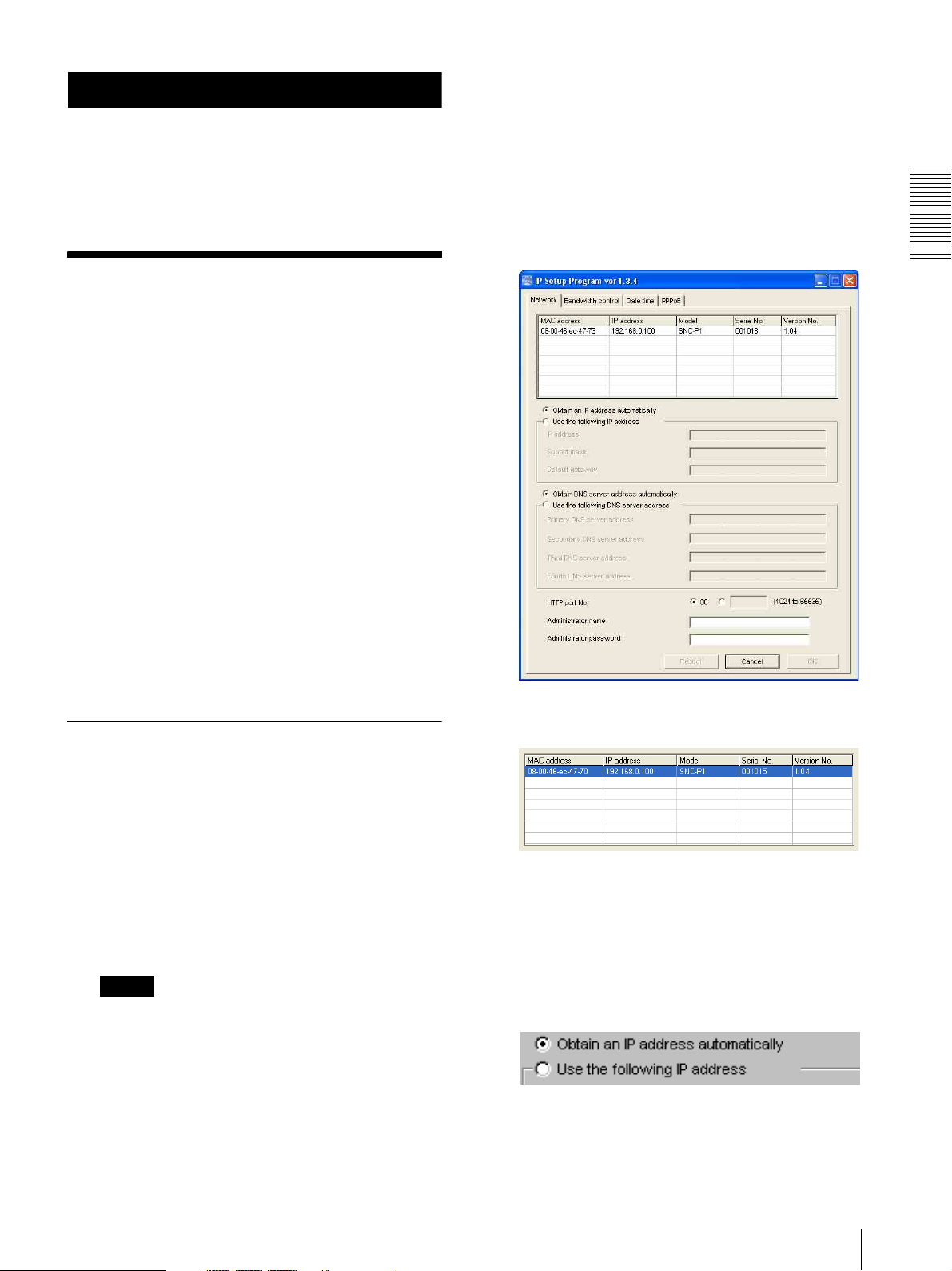
The program detects the SNC-P1 cameras
connected to the local network and lists them on the
Network tab window.
Preparation
Before starting, connect the camera to a local network,
referring to “Connections” in the supplied Installation
Manual.
Consult the administrator of the network about the
assigned IP address.
Assigning the IP Address Using the Setup Program
1
Insert the supplied CD-ROM disc into your CDROM drive.
After a short time a window will open displaying
the files on the CD-ROM.
2
Click the Setup icon of IP Setup Program.
The “File Download” dialog opens.
3
Click Open.
Note
If you click “Save this program to disk” on the “File
Download” dialog, you cannot install correctly.
Delete the downloaded file, and click Setup icon
again.
6
Click on the camera to which you want to assign a
new IP address in the list.
The network settings for the selected camera are
displayed.
7
Set the IP address.
To obtain the IP address automatically from a
DHCP server:
Select Obtain an IP address automatically.
The IP address, Subnet mask and Default gateway
are assigned automatically.
Assigning the IP Address to the Camera
9
Page 10
Preparation
To specify the IP address manually:
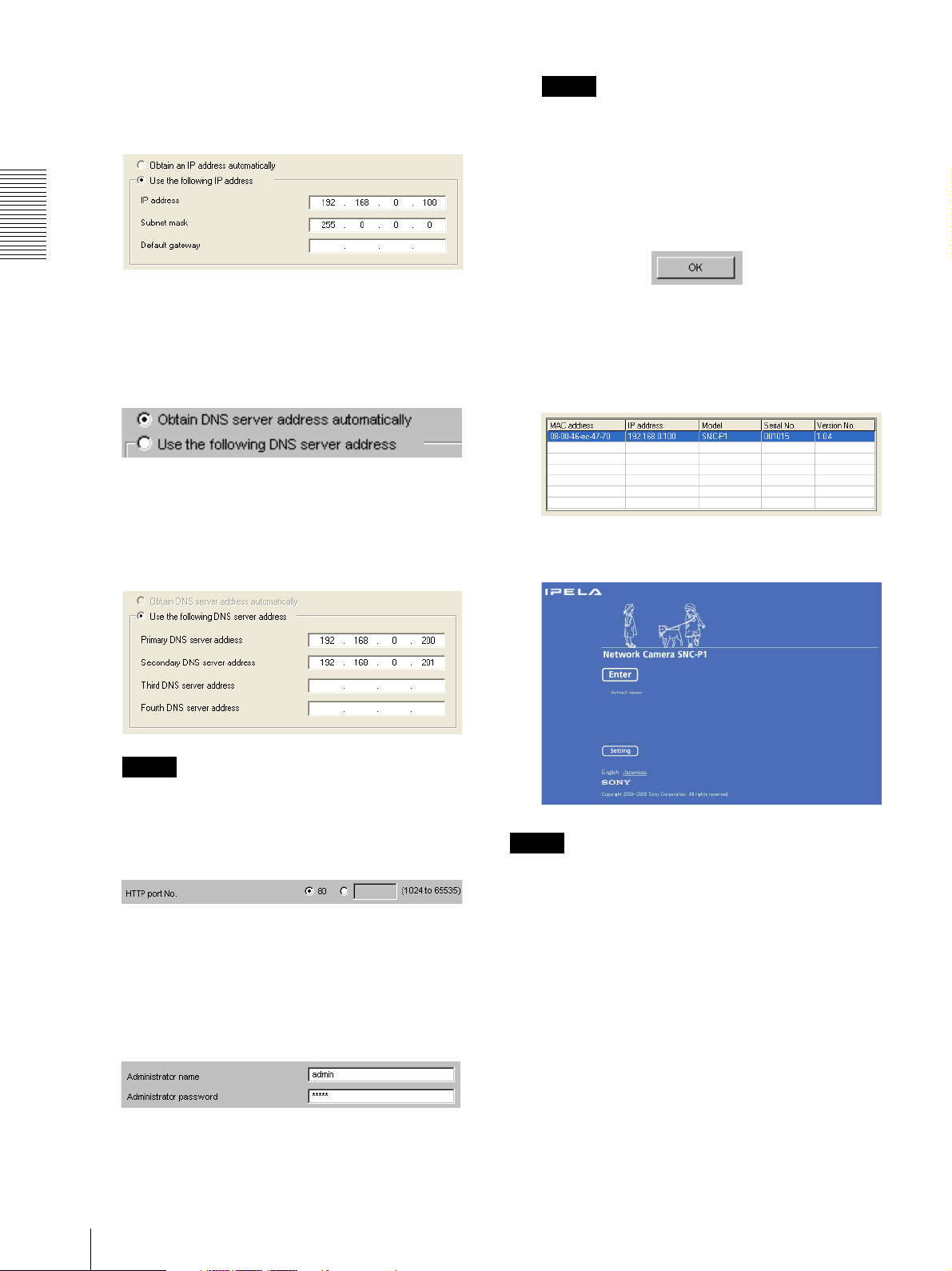
Select Use the following IP address, and type the
IP address, Subnet mask and Default gateway in the
relevant boxes.
8
Set the DNS server address.
To obtain the DNS server addresses
automatically:
Select Obtain DNS server address automatically.
To specify the DNS server addresses manually:
Select Use the following DNS server address, and
type the Primary DNS server address and
Secondary DNS server address in the relevant
boxes.
Note
You cannot change the Administrator name and
Administrator password in this step. To change
these items, See “Setting the User — User setting
Menu” on page 37.
11
Confirm that all items are correctly set, then click
OK.
If “Setting OK” is displayed, the IP address is
correctly assigned.
12
To access the camera directly, double-click the
camera name on the list.
The welcome page of the network camera SNC-P1 is
displayed.
Note
The Third DNS server address and Fourth DNS
server address are invalid for this camera.
9
Set the HTTP port No.
For usual case, select 80 for the HTTP port No. To
use another port number, type the port number
between 1024 and 65535 in the text box.
10
Type the Administrator name and Administrator
password.
The default settings of both items are “admin.”
Note
If the IP address is not set correctly, the welcome page
does not appear after step 12. In this case, try to set the
IP address again.
10
Assigning the IP Address to the Camera
Page 11
Accessing the Camera Using the Web Browser
When the IP address has been assigned to the camera,
check that you can actually access the camera using the
Web browser installed in your computer.
Use Internet Explorer as the Web browser.
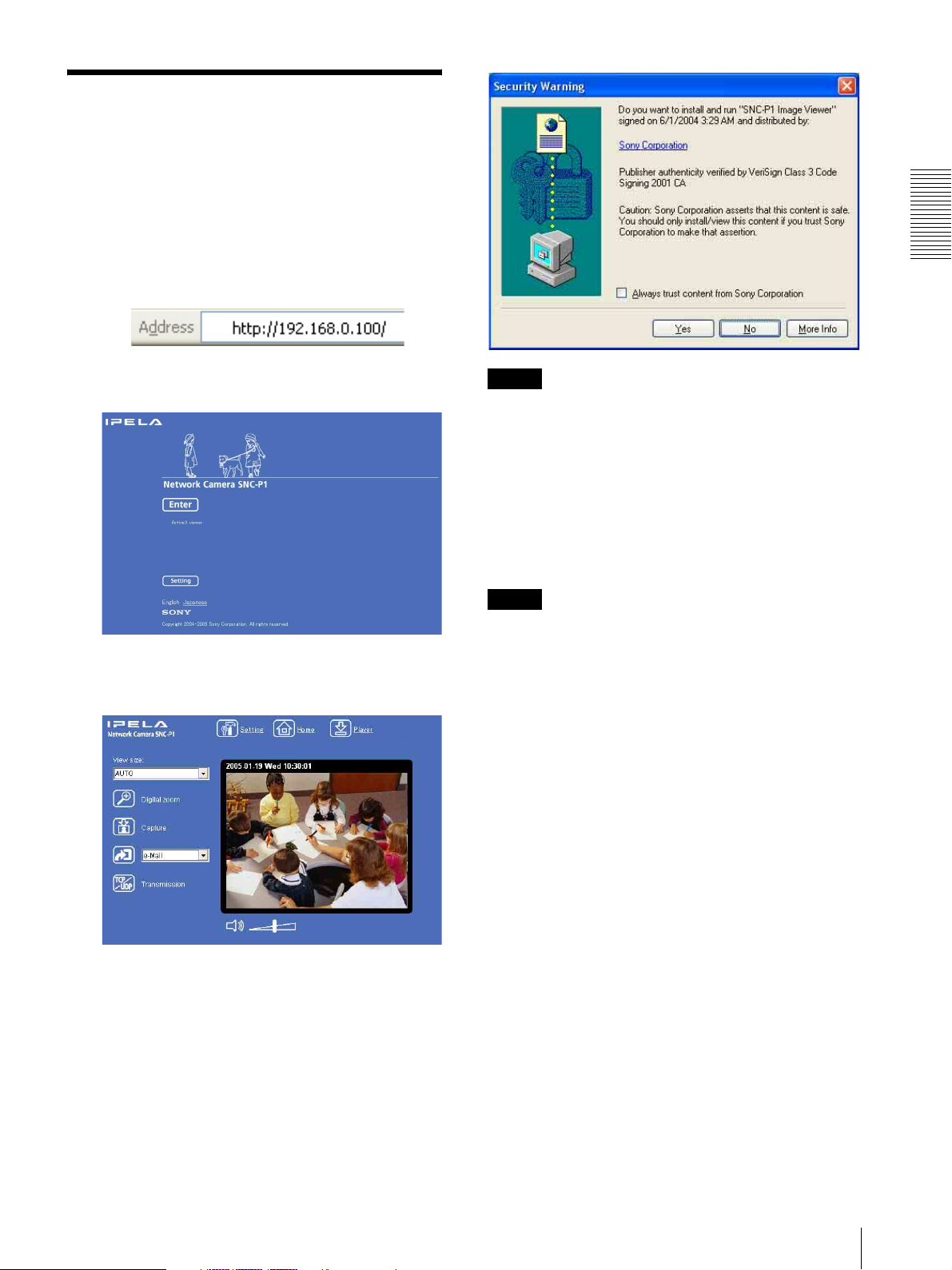
1
Start the Web browser on the computer and type the
IP address of the camera in the URL box.
The welcome page of “Network Camera SNC-P1”
is displayed.
2
Click Enter.
The main viewer is displayed.
Preparation
Notes
• If Automatic configuration is enabled in the Local
Area Network (LAN) Settings on Internet Explorer,
the image may not be displayed. In this case, disable
Automatic configuration and set the Proxy server
manually. For setting the Proxy server, consult your
network administrator.
• When you install ActiveX viewer on Windows 2000
or Windows XP, you should have logged in the
computer as the Administrator.
Tip
Every page of this software is optimized as display
character size Medium for Internet Explorer.
To display the Welcome page correctly
To operate the welcome page correctly, set the security
level of the Internet Explorer to Medium or lower, as
follows:
When the main viewer is correctly displayed, the IP
address assignment is completed.
When the main viewer of the camera is
displayed for the first time
When you click Enter, “Security warning” is displayed.
When you click OK, the ActiveX control is installed and
the main viewer is displayed.
1
Select Too l from the menu bar for Internet
Explorer, then select Internet Options and
Security tab in sequence.
2
Click the Internet icon (when using the camera via
the Internet) or Local intranet icon (when using
the camera via a local network).
3
Set the slider to Medium or lower. (If the slider is
not displayed, click Default Level.)
When using antivirus software in the
computer
• When you use antivirus software in your computer, the
camera performance may be reduced, for example, the
frame rate for displaying the image may be lower.
• The Web page displayed when you log in to the
camera uses Java Script. The display of the Web page
may be affected if you use antivirus software in your
computer.
Accessing the Camera Using the Web Browser
11
Page 12
Preparation
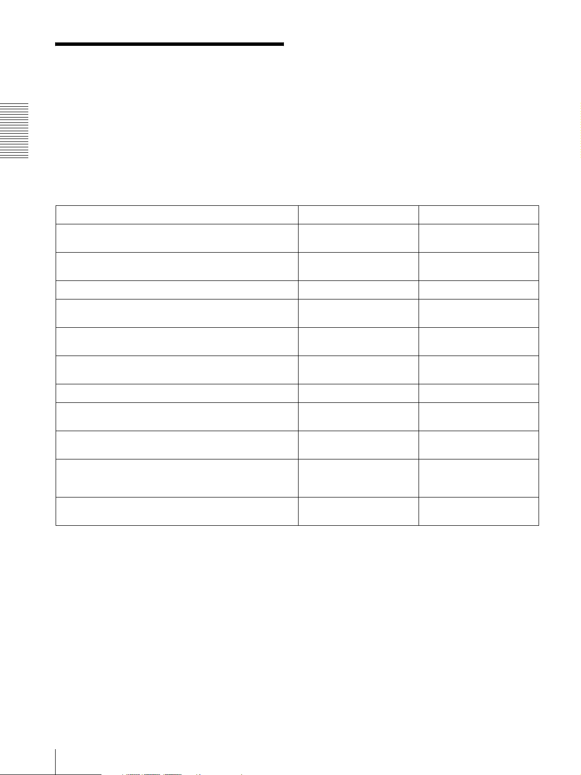
Basic Configuration by the Administrator
You can monitor the image of the camera by logging in
with the initial condition of this network camera. You
can also set various functions according to the install
position, network condition or purpose of the camera.
We recommend you configure the following items
before monitoring the image from the camera.
Setting contents Easy mode menu Advanced mode menu
Select the white balance mode according to the installing
position (indoor or outdoor).
Flip the image according to the installation position (desk top or
ceiling).
Select the brightness of the blue LED on the top of the camera. Blue LED (page 23) Blue LED (page 27)
Set the format of the image sent from the camera (MPEG 4 or
JPEG).
Select the brightness of the image sent from the camera. Brightness (page 23) Exposure mode (page 31)
Select the quality of the image sent from the camera. Image quality (page 23) MPEG4 Tab (page 32)
Select the size of the image sent from the camera. Image size (page 23) Image size (page 30)
Select weather the audio from the camera microphone is sent or
not.
Accord date and time of the camera with those of the computer. Date & time setting
Make the setting for sending the monitor image attached to a
mail.
Set the access right of the user for the camera. – Security setting Menu
White balance (page 22) White balance (page 31)
Mount (page 22) Image flip (page 30)
– Video mode (page 29)
Brightness (page 31)
JPEG Tab (page 32)
Microphone (page 23) Microphone (page 30)
(page 23)
e-Mail (SMTP) (page 23)
Easy mode (e-Mail)
(page 23)
Date & time Tab (page 27)
e-Mail (SMTP) setting Menu
(page 39)
(page 38)
12
Basic Configuration by the Administrator
Page 13

Operating the Camera
The Operating the Camera section explains how to
monitor the image from the camera using the Web
browser. Use Internet Explorer as the Web browser.
The functions of the camera should be set by the
Administrator. For setting the camera, see
“Administrating the Camera” on page 22.
Function Administrator
Switch the TCP/
UDP transmission
mode (Available in
MPEG4 mode
only)
Control the audio z zzz
Control the setting
menu
z Usable function
zz––
z –––
Full Light View
User
– Not usable function
Administrator and User
This network camera classifies the people who log in as
the Administrator and the User.
The Administrator can use all functions of this network
camera including camera setting. The functions the
User can use are monitoring the image and audio from
the camera, and controlling the camera. The Viewer
mode setting restricts the user's access right, and the
user is classified as the one of three types.
Each type of the user can use the following functions.
Function Administrator
Monitor a live
image
Watch date and
time
Control the frame
rate (Usable only
when JPEG mode
is selected)
Control the image
view size
Zoom a image by
the digital zoom
Save the still image
in the computer
Send an image file
to the FTP server
Send an image
attached to a mail
Record an image
on the inside
memory of the
camera
Control the Alarm
out of the I/O port
on the camera main
unit
z zzz
z zzz
zz––
zzz–
zzz–
zzz–
zz––
zz––
zz––
zz––
Full Light View
User
The access rights of the administrator and the user can
be set in “Setting the User — User setting Menu” on the
Advanced mode menu for the administrator on page 37.
Operating the Camera
Administrator and User
13
Page 14
Logging in to Homepage
— Welcome Page
Logging in as a User
1
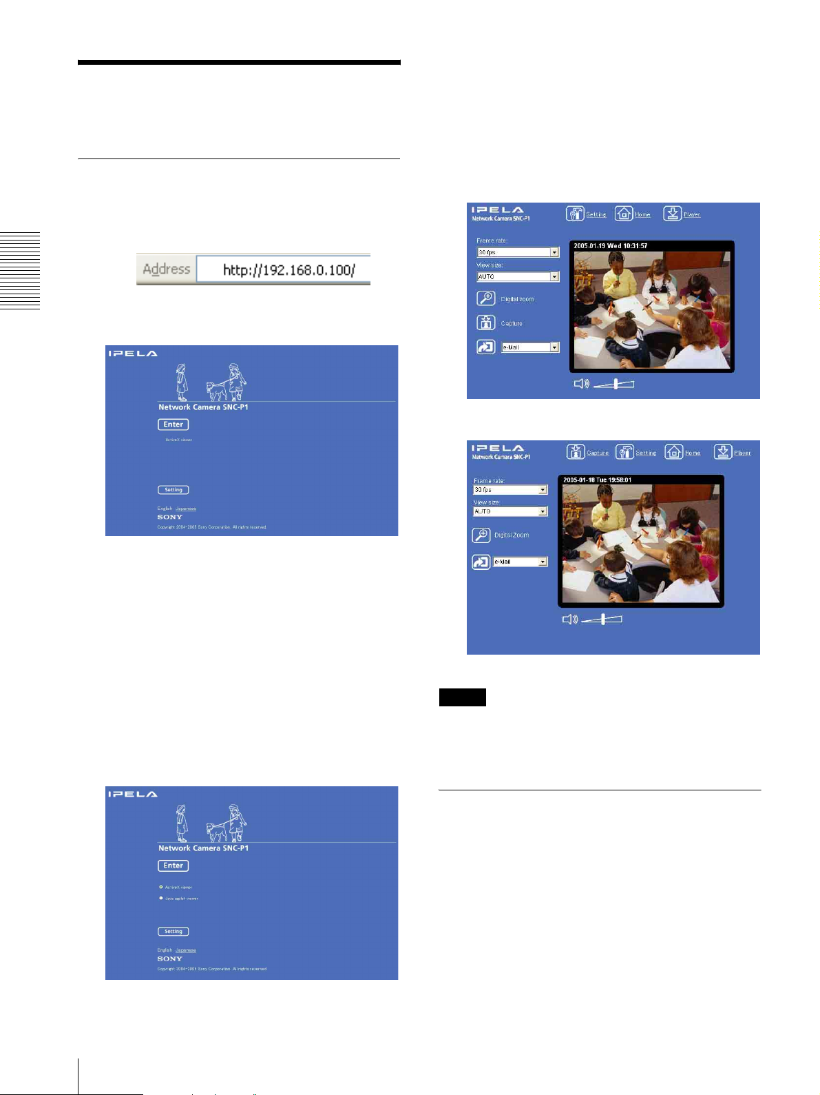
Start the web browser on the computer and type the
IP address of the camera you want to monitor.
3
Select the viewer language.
Click English or Japanese at the bottom of the
welcome page.
4
Click Enter.
The main viewer appears.
With the ActiveX viewer
Operating the Camera
The welcome page of Network Camera SNC-P1
is displayed.
2
Select the viewer.
The usable viewers differ depending on the video
mode (page 29) of the camera.
When the video mode is set to MPEG4, you can
only select ActiveX viewer, and may not select
other viewers. (MPEG4 is default. See illustration
on Step 1 above.)
When the video mode is set to JPEG, you can
select ActiveX viewer or Java applet viewer.
For details, see “About Viewers” on page 15.
Welcome page when the video mode is
JPEG
With the Java applet viewer
Control the camera from the main viewer.
Note
If the Welcome page does not activate correctly, the
security level of the Internet Explorer may be set to
Medium or higher. See “To display the Welcome page
correctly” on page 11 and check the security level.
14
Logging in to Homepage — Welcome Page
Displaying the setting window for the administrator directly
When the administrator sets the camera functions, the
setting window can be displayed directly from the
welcome page.
Page 15

1
Click Setting on the welcome page.
The following dialog appears.
2
Enter the user name and password for
Administrator, then click OK.
The user name “admin” and the password “admin”
are set at the factory for the Administrator. You can
change them in the User setting menu of the
Advanced mode menu (see page 37).
Java applet viewer
You can select this viewer when the camera video mode
is set to JPEG. The frame rate is lower than the ActiveX
viewer.
The Java applet viewer operates only when Java is
installed and Java (Sun) is enabled. If it does not
operated correctly, check if the specified Java version
has been installed successfully and Java (Sun) is
enabled.
To check the Java version
Select Tool from the menu bar of Internet Explorer, then
select Internet Option and the Advanced mode tab in
sequence, and check the version of Java displayed in
Java (Sun) is one of the versions specified below. If the
item Java (Sun) is not displayed, Java is not installed.
You need to install Java.
Java Plug-in Ver. 1.4.2_01, Ver. 1.4.2_02, Ver. 1.4.2_03,
Ver. 1.4.2_04
Operating the Camera
The Advanced mode menu appears.
About Viewers
You can use the following viewer according to the Video
mode setting in the camera setting menu of the
Advanced mode menu (page 29).
ActiveX viewer
This viewer can monitor the image in both MPEG4 and
JPEG video modes.
You must install this viewer when you access to the main
viewer at the first time.
To enable Java Plug-in
Check “Use Java2v1.4.2_xx for <applet> (requires
restart)” in “Java (Sun)”.
To install Java Plug-in
Download Java 2 Runtime Environment, Standard
Edition (JRE) from the homepage of Sun Microsystems,
Inc., and install it by following the instructions on the
installer.
Notes
• If Automatic configuration is enabled in the Local
Area Network (LAN) Settings of Internet Explorer,
the image may not be displayed. In this case, disable
Automatic configuration and set the Proxy server
manually. For setting the Proxy server, consult your
network administrator.
• When you install ActiveX viewer on Windows 2000
or Windows XP, you should have logged in to the
computer as the Administrator.
Tip
Every page of this software is optimized to display
character Medium size for Internet Explorer.
When you display the main viewer of the
camera for the first time
When you log in the network camera using ActiveX
viewer for the first time (clicking Enter to enter the
main viewer), the Security Warning appears. Click Ye s
and install ActiveX Control. You can use all the
functions of the viewer by using ActiveX Control.
Logging in to Homepage — Welcome Page
15
Page 16
Configuration of Main
Camera Control Section
Viewer
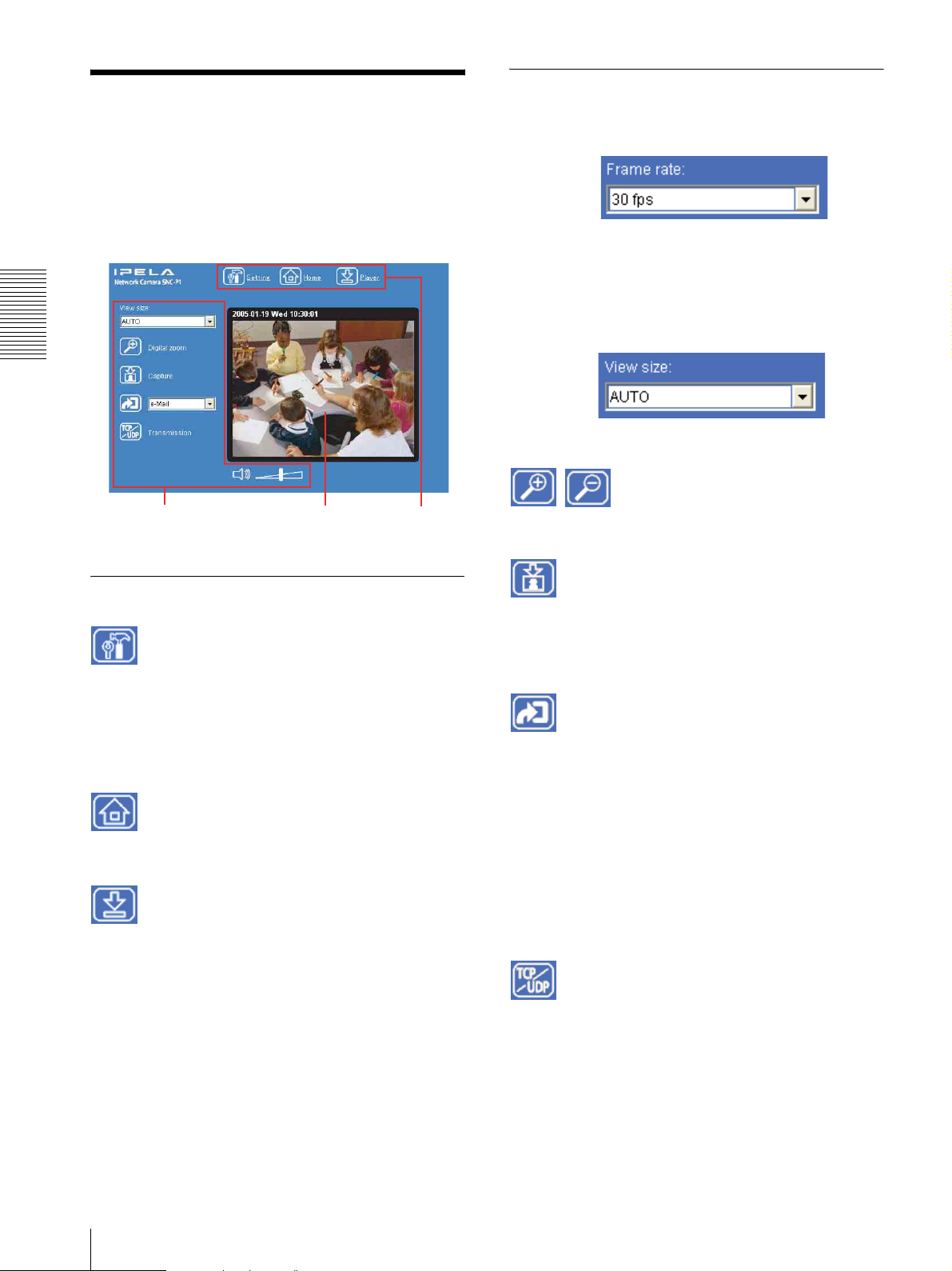
This section explains the functions of the parts and
controls of the main viewer. For a detailed explanation
on each part or control, see the specified pages.
Main viewer
Frame rate
(Displayed only when the camera Video mode (page 29)
is set to JPEG.)
Selects the frame rate to transmit images.
View size
Operating the Camera
Selects the view size to be displayed. (page 18)
Camera control
section
Monitor image
section
Main menu
Main menu
Setting
Click to display the Easy mode menu for Administrator
menu. (See “Basic Operations of Easy mode” on page
22.)
You can operate this function only when logging in as
the administrator.
Click to change the size of the digital zoom. (page 18)
Capture
Click to capture a still image shot by the camera and to
store it in the computer. (See “Capturing a Monitor
Image” on page 18.)
Trigg e r
(Displayed only when the camera Viewer mode
(page 37) is set to Full and one or more triggers are
enabled on the Trigger Setting menu (page 49).)
Digital zoom
Home
Displays the Welcome page.
Player
Click to download the “SNC video player” application
program built in the camera. The SNC video player
allows you to play video/audio data recorded on the
camera with your computer. (See “Using the SNC video
player — Playing Video/Audio File Recorded on
Camera” on page 58.)
16
Configuration of Main Viewer
Select the function you want to use from the list box and
click the icon. Then you can send the monitor image of
the camera to an FTP server (page 19), send it attached
to a mail (page 19), record the image on the built-in
memory (page 20) and switch the Alarm out to On/Off
(page 20).
Transmission (Switching the TCP/
UDP transmission mode)
(Displayed only when the camera Video mode (page 29)
is set to MPEG4 and using the ActiveX viewer.)
Each click switches the transmission mode of the video/
audio data among TCP mode, UDP (Unicast) mode and
UDP (Multicast) mode. (page 21)
The last selected mode is saved in the computer, and will
stay selected for the next starting.
Page 17
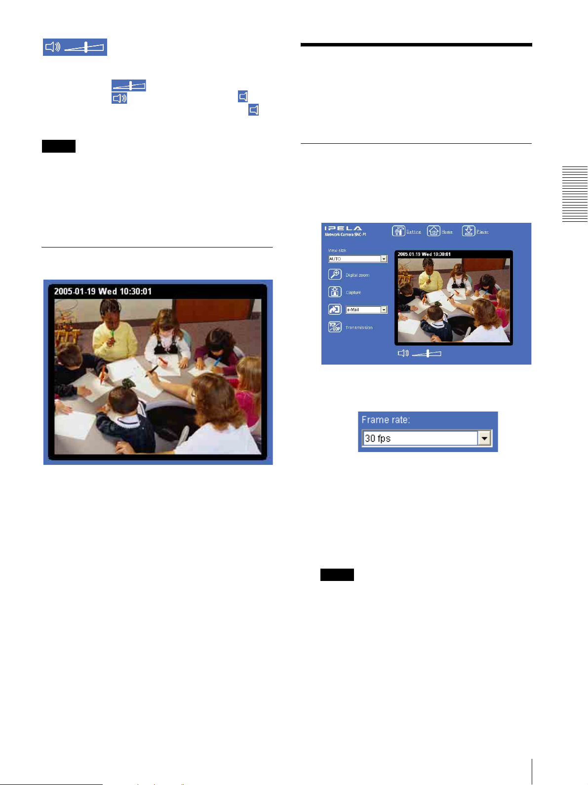
(Volume)
(Displayed when the Microphone (page 30) is set to
On.)
Drag the bar of icon to adjust the volume.
When you click icon, the icon changes to and
the audio output stops. To output the audio, click
again.
Controlling the Monitor Image
You can monitor the camera image on the monitor
window of the main viewer.
Note
If the volume icon is not displayed due to the use of
using Java applet viewer, Audio codec may not be set
G.711(64kbps) (page 30) or Java may not be installed
correctly.
To check if Java is installed correctly, refer to “Java
applet viewer” of “About Viewers” on page 15.
Monitor Image
Monitoring the camera image
1
Log in to the home page to display the main viewer.
You can see how to log in on page 14, “Logging in
as a User”.
2
Select the frame rate (only when the camera Video
mode is set to JPEG).
Operating the Camera
The image shot by the camera is shown here. Date and
time is displayed at the top of the window.
Click the Frame rate list box to select the frame
rate for transmitting the image. Selectable frame
rates are 1, 2, 3, 4, 5, 6, 8, 10, 15, 20, 25 and 30 fps.
The number means the frame number transmitted
per 1 second.
If you select 30 fps, the image is sent at the
maximum speed of the connected line (30 fps
maximum).
Note
The frame rate options indicate the maximum
number of frames that can be transmitted.
The number of frames actually transmitted may
vary depending on network environments and
camera settings (image size and image quality
settings).
Controlling the Monitor Image
17
Page 18
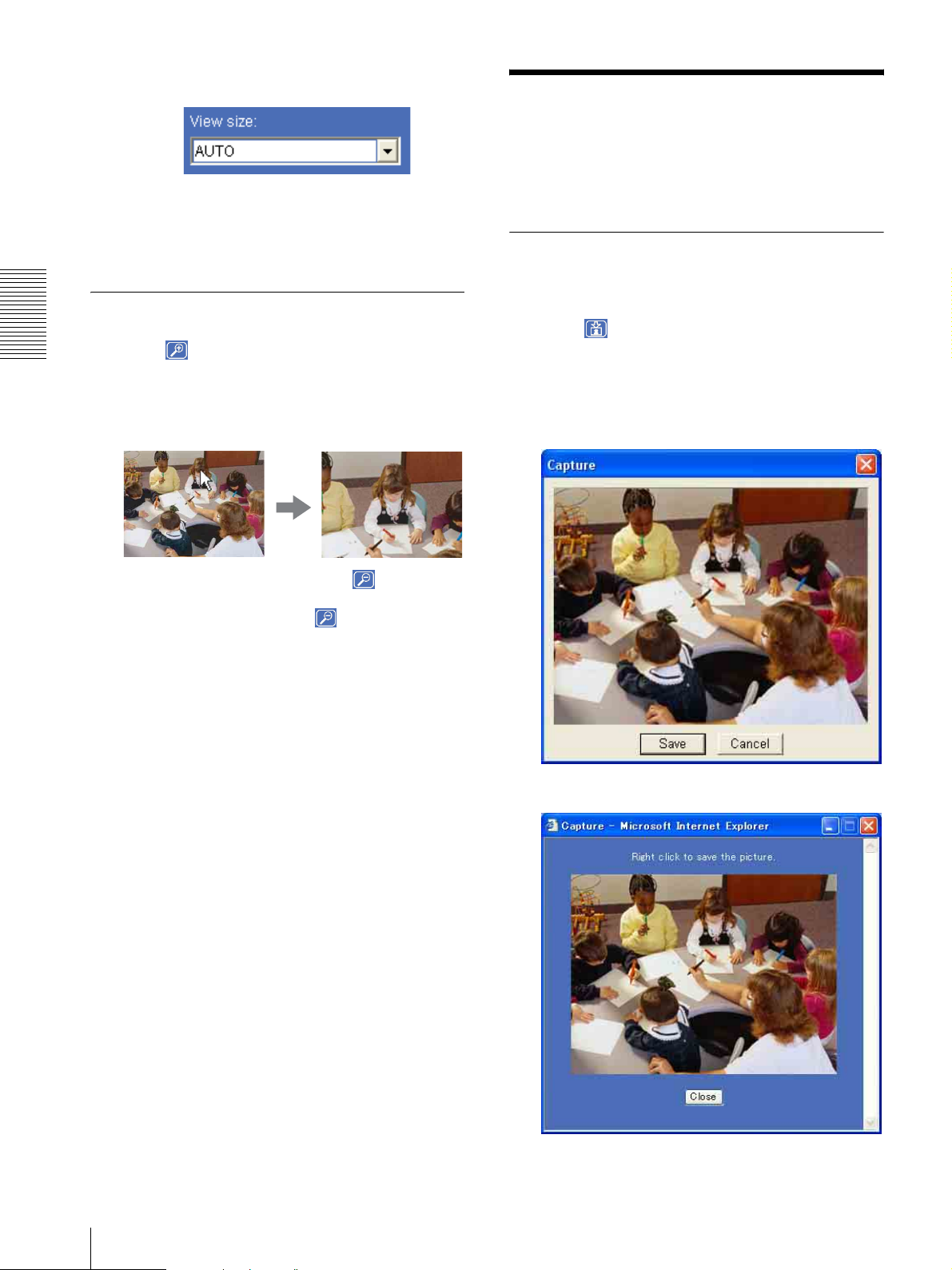
3
Select the view size.
Capturing a Monitor Image
You can capture a monitoring image as a still image and
Click View size list box to select the view size from
among Auto, 640 × 480, 320 × 240 and 160 × 120.
Aut o is determined by the image size specified in
the Camera setting page (page 30).
Zooming in the monitor image
1
Operating the Camera
Click Digital zoom icon.
2
Click the point you want to zoom in.
The image is expanded by about 1.5 times with the
clicked point at the center.
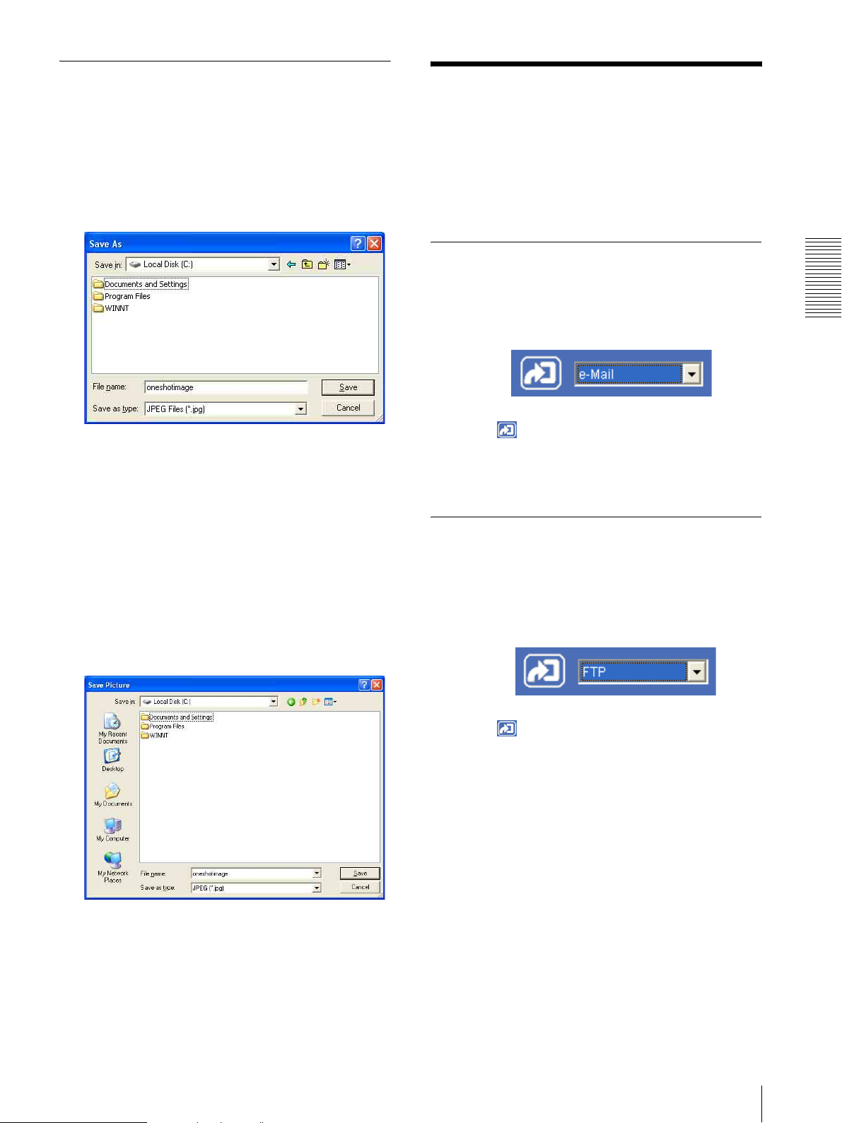
save it in the computer.
Capturing a monitor image
1
Monitor the camera image in the monitor window.
2
Click Capture icon.
The still image of the moment you click is captured,
and the still image is displayed in the monitor
window.
With the ActiveX viewer
The digital zoom icon changes to .
3
To cancel zooming in, click icon.
With the Java applet viewer
18
Capturing a Monitor Image
3
To cancel the still image, click Cancel or Close.
Page 19
Saving the captured image
Sending an Image File
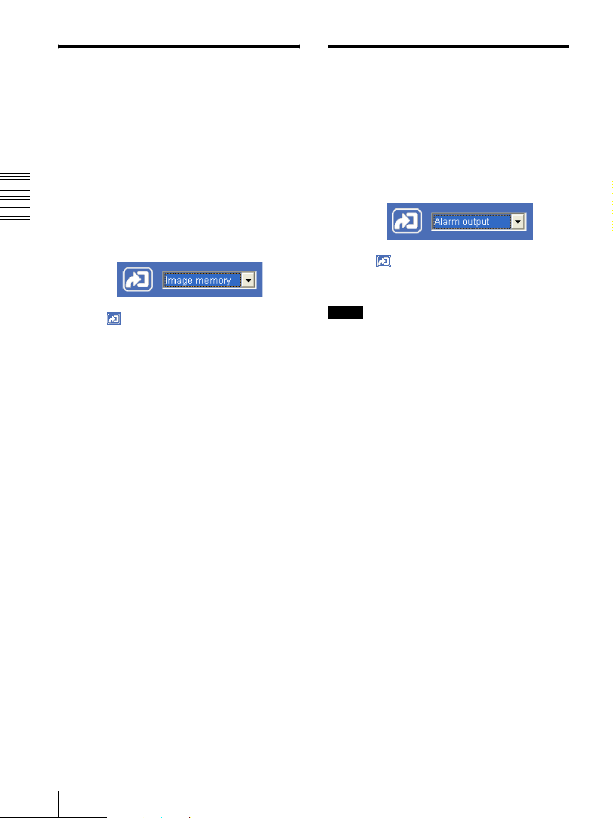
With the ActiveX viewer
1
Capture the monitor image.
2
Click Save.
Save As dialog appears.
3
Select JPEG or Bit map as Save as type.
4
Type the File name and specify Save in, then click
Save.
You can send a captured still image with an attached
mail or to the FTP server.
To use this function, you need to make the e-
Mail(SMTP) and FTP client active, and set the address
properly in the Trigger setting menu on the Advanced
mode menu (page 49).
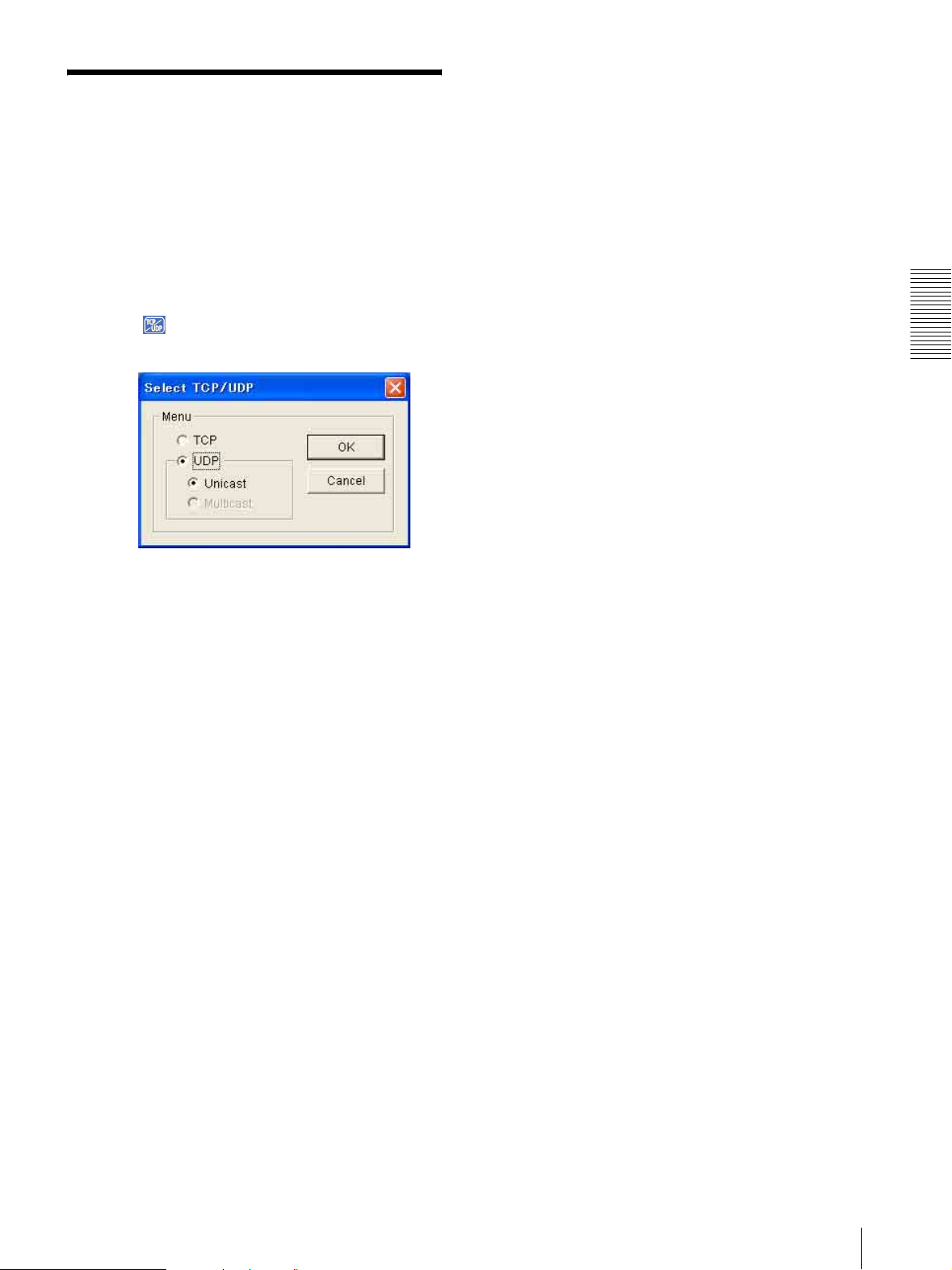
Sending a Monitor Image via e-Mail
1
Monitor the image on the monitor window.
2
Select e-Mail from the Trigger list box.
3
Click Trigger icon.
The still image of the moment when you click is
captured, and the mail attached with the image file
is sent to the mail address you have set.
Operating the Camera
With the Java applet viewer
1
Capture the monitor image.
2
Right-click the mouse to display the menu and
select Save with a new name.
Save Picture dialog appears.
3
Select JPEG or Bit map as Save as type.
Sending a Monitor Image to an FTP Server
1
Monitor the image on the monitor window.
2
Select FTP from the Trigger list box.
3
Click Trigger icon.
The still image of the moment when you click is
captured, and the image file is sent to the FTP
server.
4
Type in File name and specify Save in, then click
Save.
Sending an Image File
19
Page 20
Recording a Still Image
Controlling Alarm output
in the Built-in Memory of
the Camera
You can capture a camera image as a still image and
record it in the built-in memory of the camera.
To use this function, you need to make Image memory
active and to set details of the image memory in the
trigger setting menu on the Advanced mode menu
(page 49).
1
Monitor the image on the monitor window.
Operating the Camera
2
Select Image memory from the Trigger list box.
3
Click Trigger icon.
The still image of the moment when you click is
captured, and the image file is recorded in the builtin memory of the camera.
You can control the Alarm output On (short-circuit) and
Off (open).
To use this function, you need to make Alarm output
active in the Trigger setting menu on the Advanced
mode menu (page 49).
1
Monitor the image on the monitor window.
2
Select Alarm output from the Trigger list box.
3
Click Trigger icon.
Each click switches the Alarm output between On
(short-circuit) and Off (open) alternately.
Tip
For the connection of peripheral devices to the Alarm
output of the I/O port, see the supplied Installation
Manual.
20
Recording a Still Image in the Built-in Memory of the Camera / Controlling Alarm output
Page 21
Switching TCP/UDP Transmission Mode
You can select the communication port of the video/
audio data as TCP or UDP.
This function can be used when the Video mode
(page 29) is set to MPEG4 and the ActiveX viewer is
used.
1
Display the main viewer.
2
Click TCP/UDP transmission selector icon.
Transmission mode selector dialog appears.
a router which does not correspond to the multicast
or the fire-wall is installed between the camera and
the computer, the video/audio may not play
properly. In this case, select TCP or UDP
(Unicast).
4
Click OK to close the dialog.
If you decide not change the transmission setting,
click Cancel.
Operating the Camera
3
Click one of the buttons TCP, UDP (Unicast) or
UDP (Multicast).
TCP: This is normally selected.
When TCP is selected as the communication port,
HTTP communication is adopted for video/audio
communication.
HTTP is the protocol used for reading a usual Web
page.
In an environment capable of reading Web page,
you can watch or listen to the video/audio by
selecting TCP port.
UDP (Unicast): When UDP (Unicast) is selected
as the communication port, RTP (Real-time
Transport Protocol) is adopted for video/audio
communication. As RTP is the protocol for running
video/audio data, video/audio can be played
smoother than when TCP (HTTP) is selected. If the
fire-wall is installed between the camera and the
computer, or depending on the network
environment, the video/audio may not play
properly when UDP (Unicast) is selected. In this
case, select TCP.
UDP (Multicast): This is selectable when the
multicast streaming (page 29) is On. When UDP
(Multicast) is selected as the transmission port,
RTP (Real-time Transport Protocol) and UDP
multicast techniques are adopted for video/audio
transmission. By selecting it, the network
transmission load of the camera can be reduced. If
Switching TCP/UDP Transmission Mode
21
Page 22
Administrating the Camera
The Administrating the Camera section explains how to
set the functions of the camera by the Administrator.
For monitoring the camera image, see “Operating the
Camera” on page 13.
Administrator setting menu includes the Easy mode
(basic setting) and the Advanced mode (detail settings
depending on the user's condition).
This section explains the basic operations of the Easy
mode and explains each option of the Easy mode, then
similarly for the Advanced mode.
Basic Operations of
Note
If you set “White balance”, “Image quality” and
“Image size” in Advanced mode to values not
shown in Easy mode, the radio button may be in the
statement that nothing is selected. In this case, you
can select it by clicking the radio button.
3
Click the radio button of the option you want to set
from among those in the Easy mode menu, or click
the setting item button to display the sub menu, and
decide details.
In the Easy mode menu, the new setting will
become active only by being selected.
For details on each setting option, see “Setting
Options of Easy mode” on page 22.
4
After setting, click .
The display returns to the main viewer.
Administrating the Camera
Easy mode
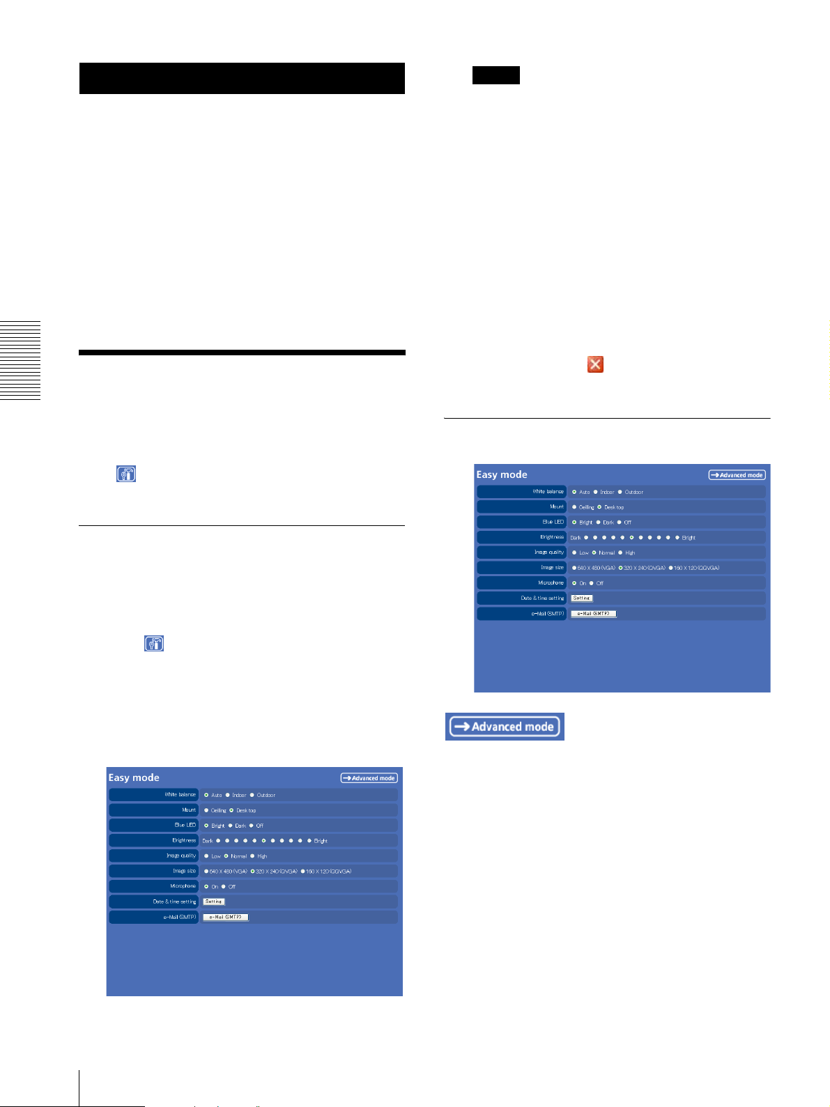
The Easy mode is used for basic settings for the network
camera.
Click Setting icon of the main viewer to display
Easy mode.
Setting Options of Easy mode
How to set Easy mode
1
Log in the home page to display the main viewer.
You can see how to log in on page 14 “Logging in
as a User”.
2
Click Setting icon.
The authentication dialog appears. Enter the user
name and password for Administrator.
The user name “admin” and password “admin” are
set at the factory for the Administrator.
Easy mode appears.
Displays the Advanced mode menu (page 25).
White balance
Select the white balance mode.
Auto, Indoor or Outdoor can be selected.
22
Basic Operations of Easy mode
Mount
The image can be displayed upside down.
Select Desk top when you use the network camera on
desktop, and select Ceiling when you use it fixed to the
ceiling. You can always watch the proper image
regardless of its position.
Page 23
Blue LED
You can select the brightness of the blue LED on the top
of the network camera.
Bright, Dark or Off can be selected.
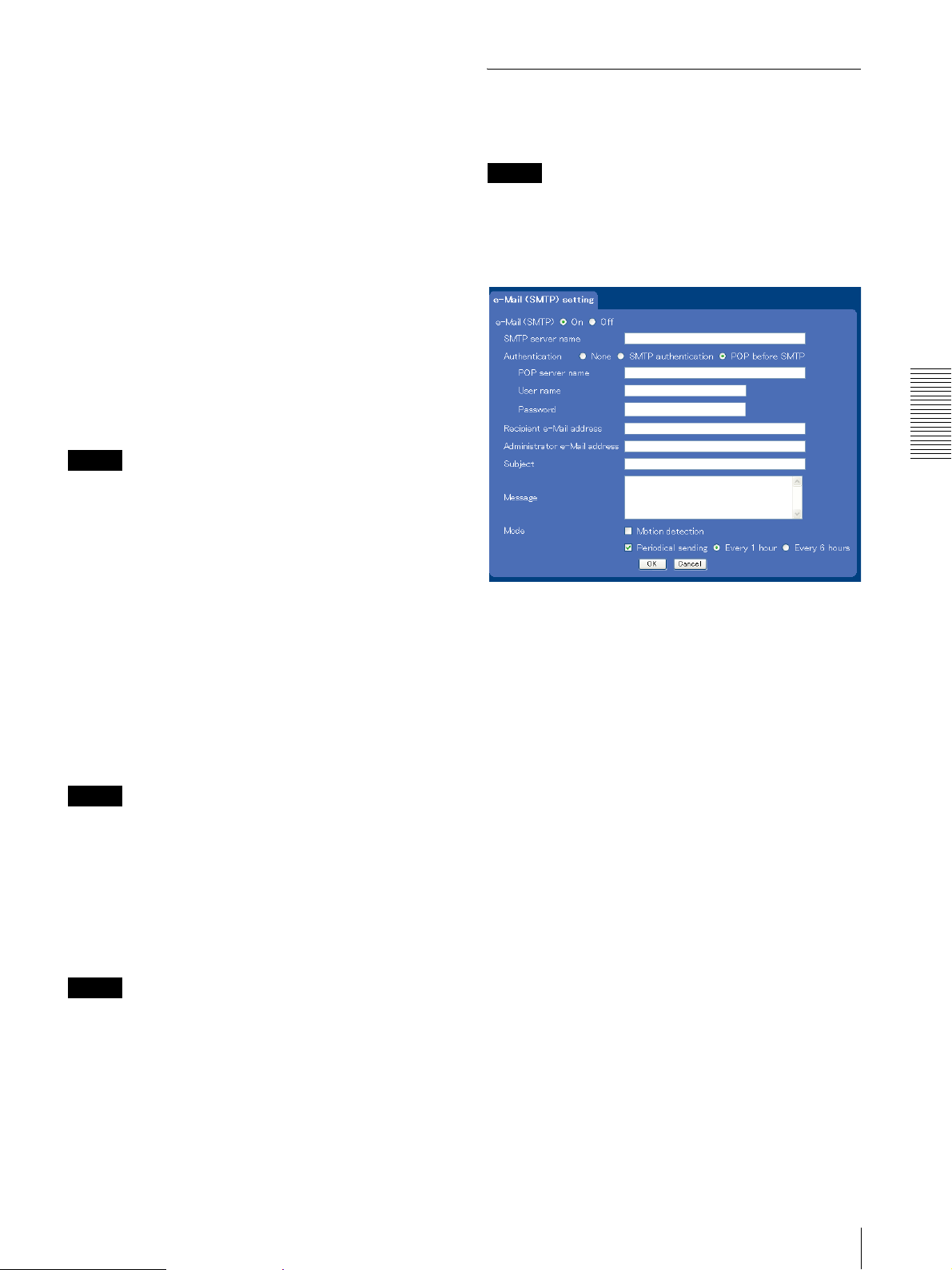
Easy mode (e-Mail)
This is displayed when you click e-Mail (SMTP) of the
Easy mode menu.
Brightness
You can adjust the brightness of the image sent from the
network camera in eleven levels.
Click the button of the brightness you want to select. The
button on the left side is the darkest (Dark), and the
button on the right is the brightest (Bright).
Image quality
You can select the quality of the image sent from the
network camera.
Usually select Normal. To give priority to the
transmission speed and to watch a smooth image, select
Low. To give priority to the image quality, select High.
Note
According to the line condition, smooth image may not
be obtained even if you select Low.
Image size
You can select the image size sent from the network
camera.
640 × 480 (VGA), 320 × 240 (QVGA) or 160 × 120
(QQVGA) can be selected.
Microphone
Select whether you send the audio from the built-in
microphone or from the m microphone input
connector. Select On to send the audio from this
network camera microphone.
Note
When you change the Microphone setting, click
Refresh of the browser to reflect the change in the
opening main viewer page.
Date & time setting
When you click Setting, date and time of the camera is
set to suit those of the computer.
Note
Note
While the camera video mode is set to MPEG4, the
image of the composite video signal output from the
video output connector of the camera may be distorted
during mail transmission.
Administrating the Camera
e-Mail (SMTP)
Select On when you use e-Mail (SMTP) function. When
you select On, setting options are displayed. If you do
not use it, select Off and click OK below.
SMTP server name
Type the SMTP (sending mail) server name up to 64
characters, or type the IP address of the SMPT server.
Authentication
Select the authentication required when you send an eMail.
None: Select when no authentication is necessary when
an e-mail is sent.
SMTP Authentication: Select when authentication is
necessary when an e-mail is sent.
POP before SMTP: Select when POP before SMTP
authentication is necessary when an e-mail is sent.
The setting time may not accord with the exact time
according to the network environment.
e-Mail (SMTP)
This is the setting for sending an e-mail with an attached
image file of the monitor. Click e-Mail (SMTP) and the
“Easy mode (e-Mail)” setting mode menu appears.
(page 23)
POP server name
Type the POP (receiving mail) server name up to 64
characters, or type the IP address of the POP server. This
setting is necessary when the SMTP server which sends
e-mails performs authentication using the POP user
account.
Basic Operations of Easy mode
23
Page 24

User name, Password
Type the user name and password of the user who has
the mail account. This setting is necessary when the
SMTP server which sends e-Mails performs
authentication.
Recipient e-Mail address
Type the address to which you send e-Mails to up to 64
characters. If you want to send to two or more addresses,
set them in the e-Mail (SMTP) setting menu (page 39) of
the Advanced mode menu.
Administrator e-Mail address
Type the e-Mail address of the administrator of the
camera up 64 characters.
This will be the address for return mail and system mail
from the mail server.
Periodical sending: The image file is sent regularly.
After checking it, select Every 1 hour or Every 6
hours.
Every 1 hour: The camera sends the e-Mail with
attached image file every 1 hour.
Every 6 hours: The camera sends the e-Mail with
attached image file every 6 hours.
OK
Click this after setting.
When you click it, the dialog "Send a test mail?"
appears. When you send a test mail to the address you
have set, select OK. If you do not wish to send it, select
Cancel.
Cancel
Click to return to the previous condition by canceling the
setting.
Subject
Administrating the Camera
Type the subject up to 64 characters.
Message
Type the text up to 384 characters (Return corresponds
to two characters).
Mode
Set the e-Mail sending mode.
Motion detection: When the camera detects any action,
it sends the image file.
If you select Motion detection, the camera detects
activity in the shooting image due to the built-in motion
detection function. Then the camera sends the e-Mail
with the attached image file.
Set the details of the motion detection of the camera in
the Motion detection setting menu (page 53) of the
Advanced mode menu.
Note
The picture attached to the e-Mail is of the moment the
motion detection function of the camera works. If the
next activity is detected during processing of the image
of the first detection, the process will be rejected.
The motion detection function may not work properly in
the following cases.
• During camera setting operation in the Camera setting
menu.
• When the object is dark.
• When the camera is shaken because the installation
location is unstable.
24
Basic Operations of Easy mode
Page 25
Basic Operations of Advanced mode Menu
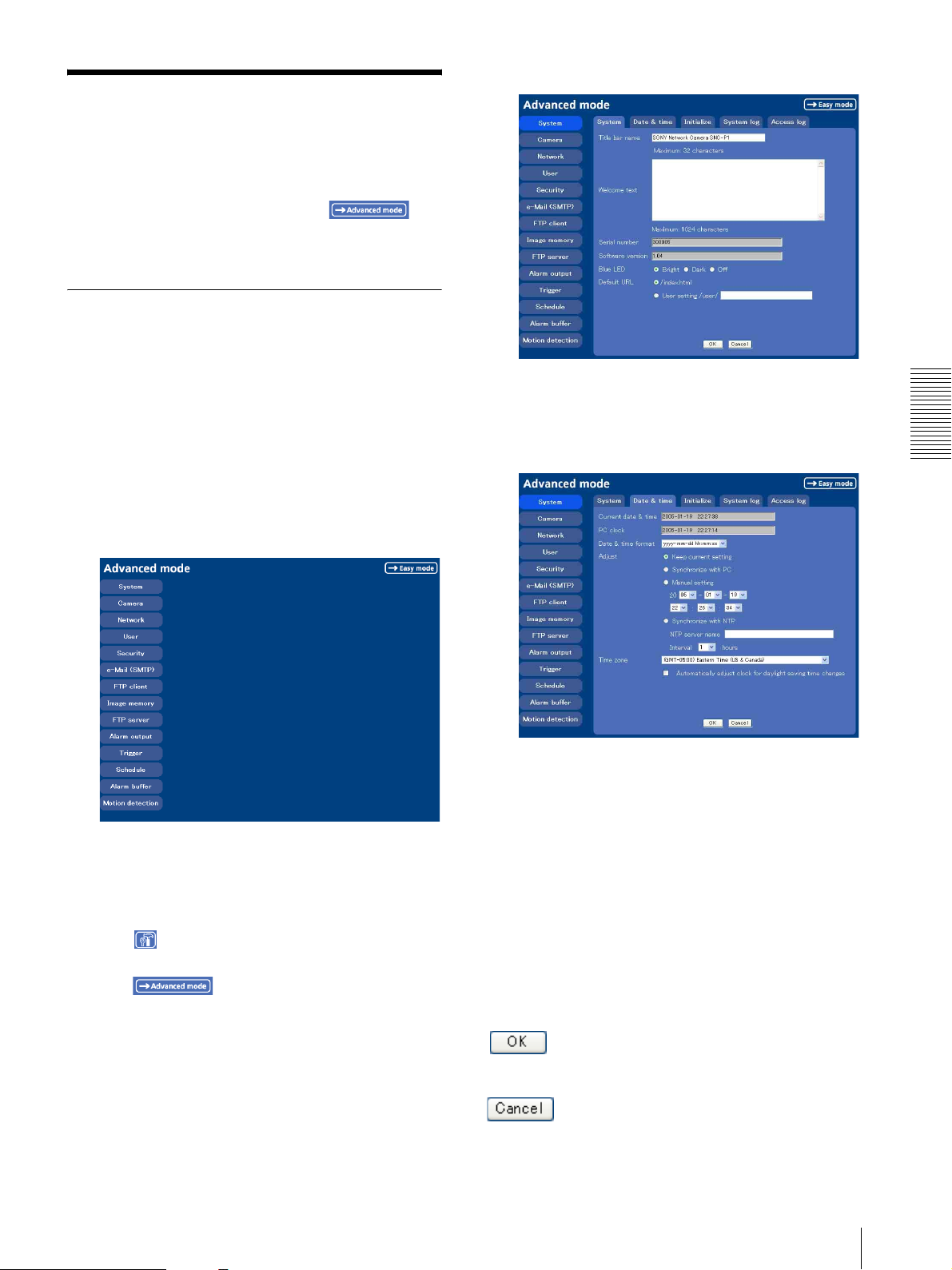
You can set all functions to suit the user's condition in
the Advanced mode menu.
Click Setting in the welcome page or
button in the Easy mode menu to display the Advanced
mode menu.
How to set Advanced mode
1
Log in the home page to display the welcome page.
You can see how to log in on page 14 “Logging in
as a User”.
2
Click Setting in the welcome page.
The authentication dialog appears. Enter the user
name and password for Administrator.
The user name “admin” and password “admin” are
set at the factory for the Administrator.
Advanced mode menu appears.
Example: System setting menu
4
Select the tab above the setting menu, and set each
setting option in the tab.
Example: “System” setting menu “Date & time”
tab
Administrating the Camera
The following steps also display the Advanced mode
menu.
1 Click Enter in the welcome page to display the main
viewer.
2 Click Setting icon in the main viewer to display
the Easy mode menu.
3 Click .
3
Click the menu name (example: System) on the left
side of the Advanced mode menu.
The clicked setting menu appears.
See page 26 to 53 for details of setting menu tabs
and setting options.
5
After setting, click OK.
The setting contents become active.
Click Cancel to invalidate the set values and return to
the previous settings.
Buttons common to every setting menu
The following buttons are displayed on the setting
menus where they are necessary. The functions of the
buttons are the same on every setting page.
Click this button to validate the settings.
Click this button to invalidate the set values and return to
the previous settings.
Basic Operations of Advanced mode Menu
25
Page 26
General note on setting menus
After changing a setting on a setting menu, wait at least
10 seconds before turning off immediately the power of
the camera.
If the power is turned off immediately, the changed
setting may not be stored correctly.
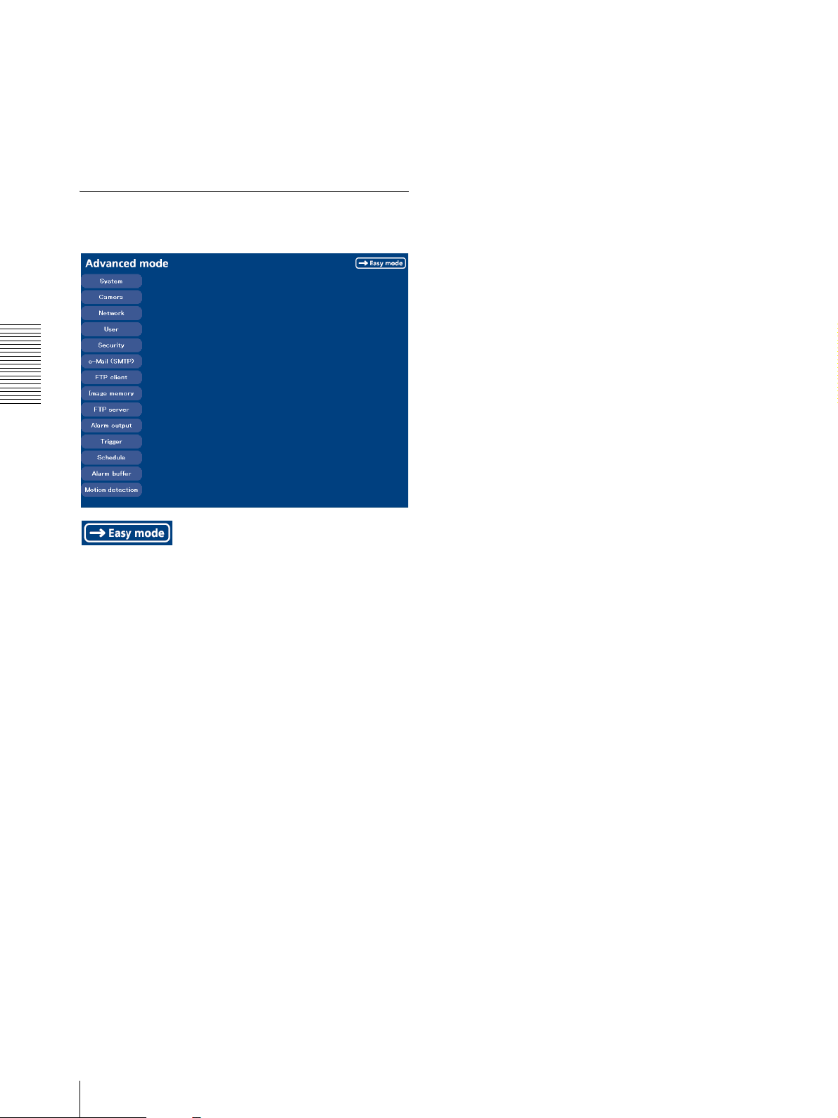
Configuration of Advanced mode
e-Mail (SMTP)
Displays the e-Mail (SMTP) setting menu for sending an
e-mail. (“Sending an Image via mail — e-Mail (SMTP)
setting Menu” on page 39)
FTP client
Displays the FTP client setting menu for sending an
image file to FTP server. (“Sending Images to FTP
Server — FTP client setting Menu” on page 42)
Menu
Administrating the Camera
Displays the Easy mode menu (page 22).
System
Displays the System setting menu.
(“Configuring the System — System setting menu” on
page 27).
Camera
Displays Camera setting menu for setting the camera
image and audio. (“Setting the Camera Image and Audio
— Camera setting Menu” on page 29)
Network
Displays the network setting menu for setting the
network connection. (“Configuring the Network —
Network setting Menu” on page 33)
Image memory
Displays the image memory setting menu for recording
a video/audio file in the built-in memory of the camera.
(“Recording Images in Memory — Image memory
setting Menu” on page 44)
FTP server
Displays the FTP Server menu for setting the FTP server
function of the camera.
(“Downloading Images from the Camera — FTP server
setting Menu” on page 48)
Alarm output
Displays the alarm out setting menu for the alarm out
terminal of the camera. (“Downloading Images from the
Camera — FTP server setting Menu” on page 48)
Trigger
Displays the trigger setting menu for the operations
when you click the trigger button in the main viewer.
(“Setting the Operations from the Viewer Page —
Trigger setting Menu” on page 49)
Schedule
Displays the schedule setting menu for FTP client
function, e-Mail (SMTP) function, Image memory
function and Alarm out function and so on. (“Setting the
Schedule — Schedule setting Menu” on page 51)
Alarm buffer
Displays the alarm buffer setting menu for the buffer
which records the image and audio on the alarm
detection. (“Setting the Alarm Buffer — Alarm buffer
setting Menu” on page 51)
User
Displays the user setting menu for setting the user name
and the password to log in. (“Setting the User — User
setting Menu” on page 37)
Security
Displays the security setting menu for specifying the
computer allowed to connect to the camera. (“Setting the
Security — Security setting Menu” on page 38)
26
Basic Operations of Advanced mode Menu
Motion detection
Displays the Motion detection setting menu for the
motion detection function built into the camera.
(“Setting the Motion Detection Function — Motion
detection setting Menu” on page 52)
Page 27
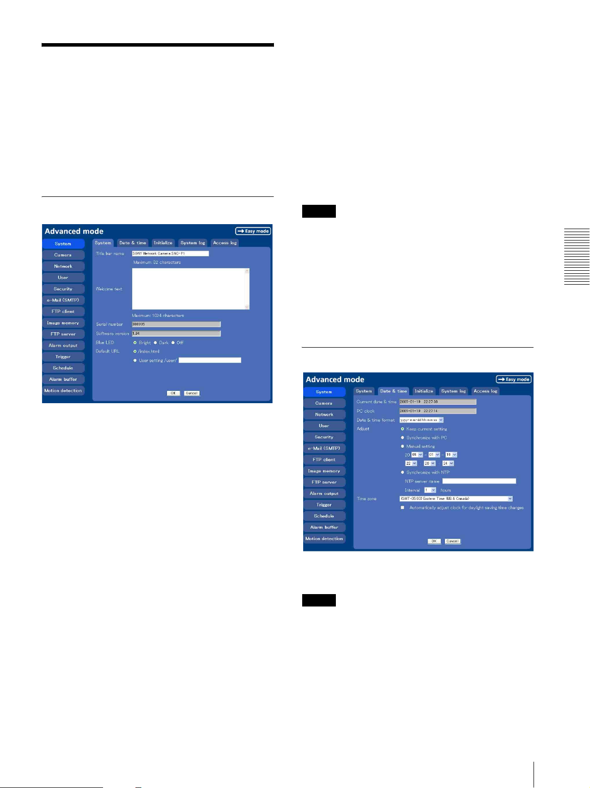
Configuring the System
— System setting menu
When you click System on the Advanced mode menu,
the System setting menu appears.
Use this menu to perform the principal settings of the
software.
The System setting menu is composed of five tabs which
are System, Date & time, Initialization, System Log
and Access Log.
System Tab
To display the homepage built in the camera
Select /index.html.
To display your individual homepage
You can display your favorite homepage. Store the
HTML file in the built-in flash memory using the
Custom Homepage Installer included in the supplied
CD-ROM.
For use of the Custom Homepage Installer, see page 59.
1
Select User Setting/user/.
2
Type the path of the HTML file in the text box up to
64 characters.
Tip
Even when you select User Setting/user/, the home
page inside the camera can be displayed by typing the
following URL in the address box of the browser.
Example: When the IP address of the camera is set to
192.168.0.100
http://192.168.0.100/en/index.html
OK/Cancel
See “Buttons common to every setting menu” on page
25.
Administrating the Camera
Title bar name
Type a name to display on the title bar up to 32
characters. The characters typed here are displayed on
the title bar of the Web browser.
Welcome text
Type a text to show on the welcome page, with up to
1024 characters in HTML format. Use the <BR> tag for
a line break. (A line break is equivalent to 2 characters.)
Serial number
Displays the serial number of the camera.
Software version
The software version of this camera is displayed.
Blue LED
You can select the brightness of the blue LED on the top
of the network camera.
Bright, Dark or Off can be selected.
Default URL
Select the homepage to be displayed when you enter the
IP address of the camera in the web address box of the
browser.
Date & time Tab
Current date & time
Displays the date and time set on the camera.
Note
After you have purchased the camera, be sure to check
the date and time of the camera and set them if
necessary.
PC clock
Displays the date and time set on your computer.
Date & time format
Select the format of date and time to be displayed on the
main viewer from the drop-down list.
Configuring the System — System setting menu
27
Page 28
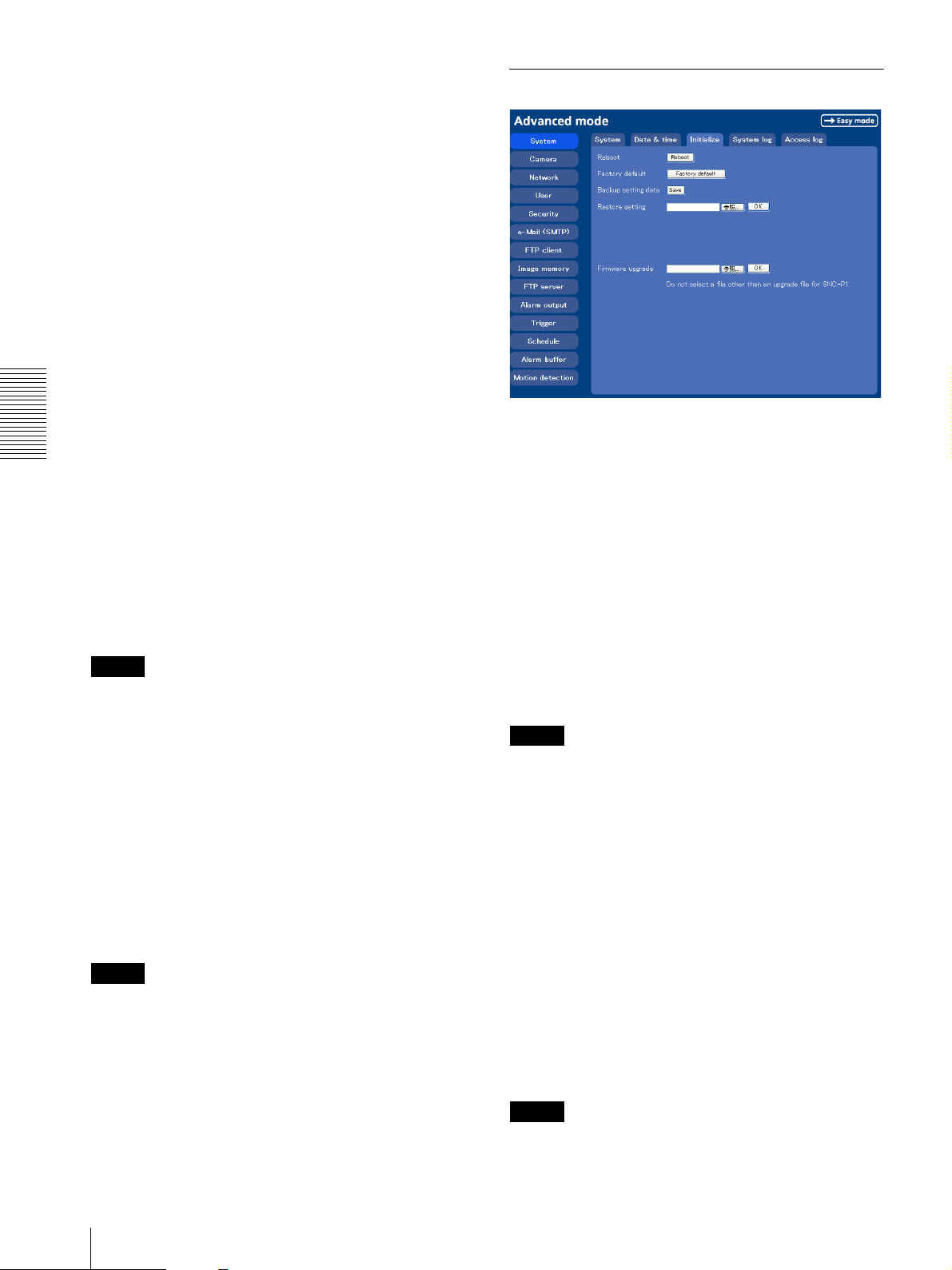
You can select from among yyyy-mm-dd hh:mm:ss
(year-month-day hour:minute:second), mm-dd-yyyy
hh:mm:ss (month-day-year hour:minute:second), and
dd-mm-yyyy hh:mm:ss (day-month-year
hour:minute:second).
Initialize Tab
Adjust
Select to set the day and time.
Keep current setting: Select if you do not need to set
the date and time.
Synchronize with PC: Select if synchronizing the
camera's date and time with those of the computer.
Manual setting: Select if you want to set the camera's
date and time manually.
Select the lower 2-digits of year, month, date, hour,
minutes and seconds from each drop-down list.
Synchronize with NTP: Select if synchronizing the
camera's date and time with those of the time sever
called NTP server (Network Time Protocol). Set the
NTP saver name and the Interval.
Administrating the Camera
NTP server name
Type the host name or IP address of the NTP server, up
to 64 characters.
Reboot
Reboots the camera.
Click Reboot, and the message “The SNC-P1 will be
rebooted. Are you sure?” appears. Click OK to reboot
the camera. It takes about two minutes to start again.
Factory default
Interval
Select the interval at which you want to adjust the
camera's time referring to the NTP server' time, between
1 and 24 hours. The set interval is a guide, and does not
indicate the exact time.
Note
The setting time may not accord with the exact time
according to the network environment.
Resets the camera to the factory settings.
Click Factory default, and the message “Set up data
will be initialized. Are you sure?” appears. When you
click OK, the network indicator and the Blue LED on
the camera start to blink. After adjustments of the
default settings have finished, the camera reboots
automatically. Do not turn off the camera until the
camera reboots.
Tip
Time zone
Set the time difference from Greenwich Mean Time in
the area where the camera is installed.
Select the time zone where the camera is installed from
the drop-down list.
Automatically adjust clock for daylight saving
time changes
When you select it, the clock is automatically adjusted
according to the daylight saving time of the selected
time zone.
Note
If the time zone selected on the Time zone menu is
different from that set on the computer, the time is
adjusted using the time zone difference and set on the
camera.
The camera can also be reset to the factory settings by
turning the power on of this unit while pressing the reset
switch on the camera. For details, see the supplied
Installation Manual.
Backup setting data
Saves the setting data of the camera in a file.
Click Save, and follow the instructions on the browser to
specify the folder and save the setting data of the
camera. The file name preset at the factory is “snc-
p1.cfg.”
Restore setting
Loads the stored setting data of the camera.
Click Browse and select the file in which the setting data
is stored. Then, click OK, and the camera is adjusted
according to the loaded data and restarted.
OK/Cancel
See “Buttons common to every setting menu” on page
25.
Note
With Restore setting, some items in the Network setting
menu (page 33) cannot be restored.
28
Configuring the System — System setting menu
Page 29

Firmware upgrade
Use this when upgrading the camera software. Click
Browse and specify the file for upgrading, then click
OK. The massage “Upgrade firmware? Are you sure?”
is displayed. Click OK and upgrading starts. After
completion, the camera starts again.
Setting the Camera
Image and Audio
— Camera setting Menu
Notes
• Use only the upgrade file special to this camera. If
not, a problem may occur.
• Do not turn off the camera until the upgrading is
completed.
System log Tab
System log
The data of the software activity of the camera are
recorded in this log. It includes data that are useful when
a problem occurs.
Click Reload to reload the latest data.
When you click Camera on the Advanced mode menu,
the Camera setting menu appears.
Use this menu to set the functions of the camera.
The Camera setting menu consists of 5 tabs: Common,
Picture, MPEG4, JPEG and Reset.
Common Tab
Administrating the Camera
Video mode
Select the output format of the camera image.
MPEG4 or JPEG can be selected.
Access log tab
Access log
The access record of the camera is displayed.
Click Reload to reload to the latest data.
Unicast streaming
Specify the transmission port number of the video data
and audio data used when UDP (Unicast) is selected
with the TCP/UDP transmission switching icon in the
main viewer
Video port number: Specify the transmission port
number of the video data. It is initially set to 50000.
Specify an even number from 1024 to 65534.
Audio port number: Specify the transmission port
number of the audio data. It is initially set to 50002.
Specify an even number from 1024 to 65534.
Multicast streaming
Set whether the camera uses the Multicast streaming or
not. It reduces sending load on the camera by making the
computer of the same segment network (not above the
router) receive the same transmitting data.
Select On to allow the multicast sending and Off not to
allow.
Setting the Camera Image and Audio — Camera setting Menu
29
Page 30
When select On, set Multicast address, Multicast
video port number and Multicast audio port number
properly.
Multicast address: Type the multicast address used on
the Multicast streaming.
Multicast video port number: Specify the video
transmission port number used for the Multicast
streaming.
Multicast audio port number: Specify the audio
transmission port number used for the Multicast
streaming.
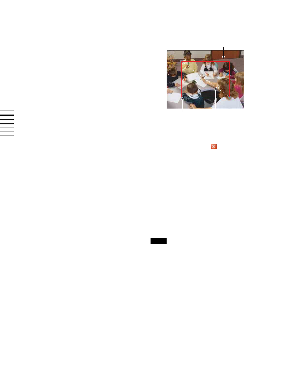
Click the left button of the mouse on the still image
and drag it diagonally. The red frame that appears
as you drag indicates the cropping area.
Still image
Image size
You can select the image size sent from the network
camera.
640 × 480 (VGA), 480 × 360, 384 × 288, 320 × 240
(QVGA), 256 × 192 or 160 × 120 (QQVGA) can be
selected.
4
Administrating the Camera
Cropping
When the image size is set to 640 × 480 (VGA), you can
crop a portion of the image and display the cropped
image on the computer. With the cropping, the
transmitting data size, and thus, the network load is
reduced and a higher frame rate is obtained.
Select On to crop the image, or Off.
• When Cropping is set to On, Motion detection
function does not work.
• While Cropping is set to On, the image of the
composite video signal output from the video output
connector of the camera may be distorted.
To crop an image
1
Set the Image size to 640 × 480(VGA).
The Cropping is displayed.
5
Color
Select Color or Monochrome for the image.
Image flip
The image can be displayed upside down. Select On
when you fix the camera to the ceiling.
Microphone
Select whether you send the audio from the built-in
microphone or from the m microphone input connector.
Select On to send the audio from this network camera.
Red trimming
frame
Click OK at the bottom of the window.
The cropped image is displayed on the main viewer.
To close the image, click in the upper-right
corner.
Click the left button of the mouse on
the still image and drag it.
2
Set the Cropping to On and click the Area setting
button.
The “Area setting” display appears.
3
Specify the cropping area.
30
Setting the Camera Image and Audio — Camera setting Menu
Note
When you change the Microphone setting, click
Refresh on the browser to reflect the change when
opening main viewer page.
Mic volume
Set the volume level of the audio input from the built-in
microphone or the m microphone input connectors. It is
adjustable from –10 to +10.
Audio codec
Select the bit rate when you send the audio from the
built-in microphone or from the m microphone input
connectors. G.711 (64kbps), G.726 (40kbps), G.726
(32kbps), G.726 (24kbps) or G.726 (16kbps) can be
selected.
Page 31
Note
When the bit rate is set to other than G.711(64bps), the
audio is not output in case of using Java applet viewer.
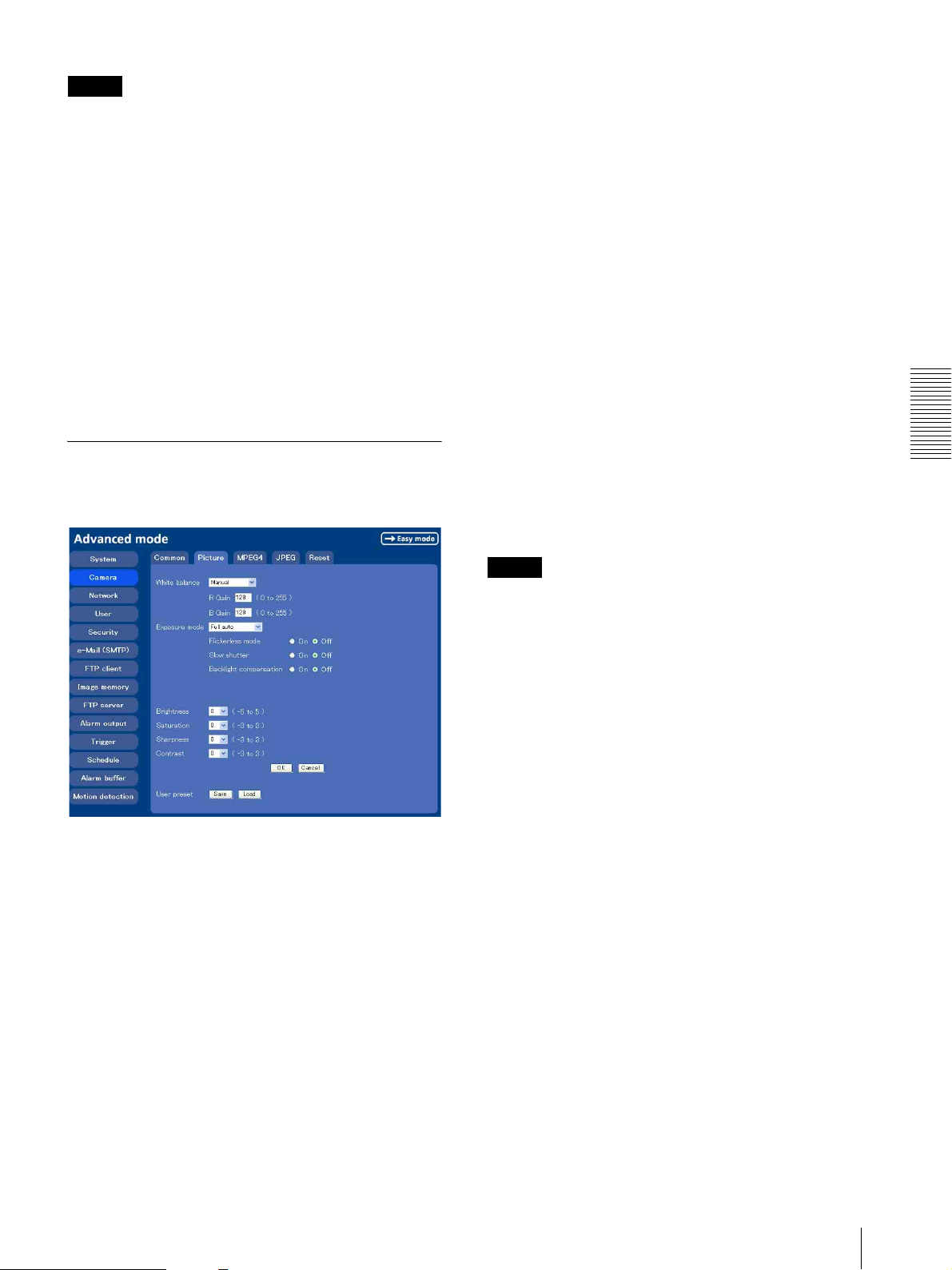
Exposure mode
Select the exposure mode of the camera from among
Full auto, Shutter priority, and Manual.
The setting items required for each setting appear.
Speaker output
Set whether you output the audio sent from the computer
connected with the audio input connector to the speaker
(active speaker for example) of the camer aconnected
via line output connectors using SNC audio upload tool
included in the supplied CD-ROM.
Select On to accept the audio data transmission from
SNC audio upload tool.
OK/Cancel
See “Buttons common to every setting menu” on page
25.
Picture Tab
You can set the color condition, exposure, etc. of the
camera.
Full auto: The camera executes the gain adjustment and
the shutter speed adjustment automatically.
When you select this, Flickerless mode, Slow
shutter and Backlight compensation are displayed
and you can set them as you require.
Shutter priority: The camera executes the gain
adjustment automatically and you can select the
shutter speed. When you select it, Backlight
compensation and Shutter speed are displayed and
you can set them.
Manual: You can set the exposure manually. When you
select it, Shutter speed and Gain are displayed and
you can set them.
According to the Exposure mode, the following setting
options are displayed.
Flickerless mode
If the image is flickering by the fluorescent light, select
On to reduce it.
Note
This mode is available only for CE model.
Slow shutter
Set the Slow shutter. When On is selected, auto
exposure setting including the long time exposure is set
to suit to the brightness of the scene.
Administrating the Camera
White balance
Select the white balance mode from among Auto,
Indoor, Outdoor, One push WB, and Manual.
Auto: to automatically adjust the white balance
Indoor: to adjust the white balance for shooting indoors
under an incandescent lamp (about 3200 K)
Outdoor: to adjust the white balance for shooting
outdoors (about 5800 K)
One push WB: The One push trigger button is
displayed. Click the button to adjust the white
balance instantly.
Manual: When you select this, R Gain and B Gain are
displayed and you can set them.
Selectable gain values are from 0 to 255.
Backlight compensation
You can set On or Off of the exposure compensation.
When you select On, the exposure compensation
function starts to work.
Shutter speed
Select the shutter speed of the camera from the list box.
Selectable values of the shutter speed are 1/10000,
1/4000, 1/2000, 1/1000, 1/500, 1/250, 1/100, 1/50, 1/30,
1/15, 1/8, 1/4, 1/2 and 1/1 second.
Gain
Select the gain from the list box.
Selectable values of the gain are 0, 6, 12 and 18 dB.
Brightness
Tweaks the exposure set in the exposure mode. It is
brighter when a large value is selected, and it is darker
when a small value is selected. The value among –5 to 5
can be set.
Saturation
Select the saturation in 7 steps, from –3 to 3.
Selecting 3 gives the image with the highest saturation.
Setting the Camera Image and Audio — Camera setting Menu
31
Page 32
Sharpness
Select the sharpness in 7 steps, from –3 to 3.
Selecting 3 gives the image with the highest sharpness.
Contrast
Select the contrast in 7 steps, from –3 to 3.
Selecting 3 gives the image with the highest contrast.
OK/Cancel
See “Buttons common to every setting menu” on page
25.
according to the image size, the shooting scene or the
network condition.
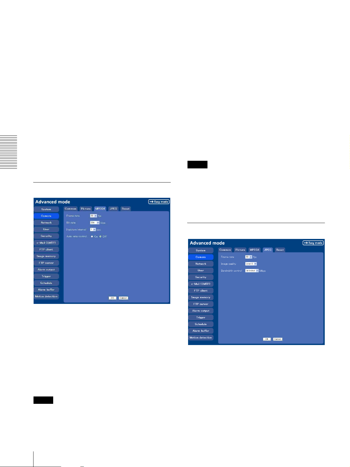
I-picture interval
Set the I-picture inserting interval of MPEG4. I-picture
is the compression data serving the basic point when the
data compressed by MPEG4 is depressed. In the
condition that errors tends to occur, such as the network
environment variation, the distortion of the image is
reduced by selecting a small value. The selectable values
are 1, 2, 3, 4 and 5 seconds.
Auto rate control
User preset
You can save the present settings in the camera as the
custom, or you can load the settings saved in the camera.
Save: Click to save the present settings of the Picture
tab.
Load: Click to load the saved settings. To use them,
Administrating the Camera
click OK.
This function adjusts the frame rate and the bit rate
automatically so that the camera plays a smooth image
to suit the connected computer environment. If On is
selected, the rate of MPEG4 image is automatically
adjusted.
Note
The maximum transmission rate will be the values set in
Frame rate and Bit rate.
MPEG4 Tab
OK/Cancel
See “Buttons common to every setting menu” on page
25.
Frame rate
Set the frame rate of the MPEG image.
Selectable values are 1, 2, 3, 4, 5, 6, 8, 10, 15, 20, 25 and
30 fps. The unit is “fps” (frame number sent per a
second).
Bit rate
Set the bit rate of MPEG image transmission for a line.
Selectable values are 64, 128, 256, 384, 512, 768, 1024,
1536 and 2048 kbps.
Note
The selected frame rate and bit rate are a tentative value.
The actual frame rate and bit rate may be different
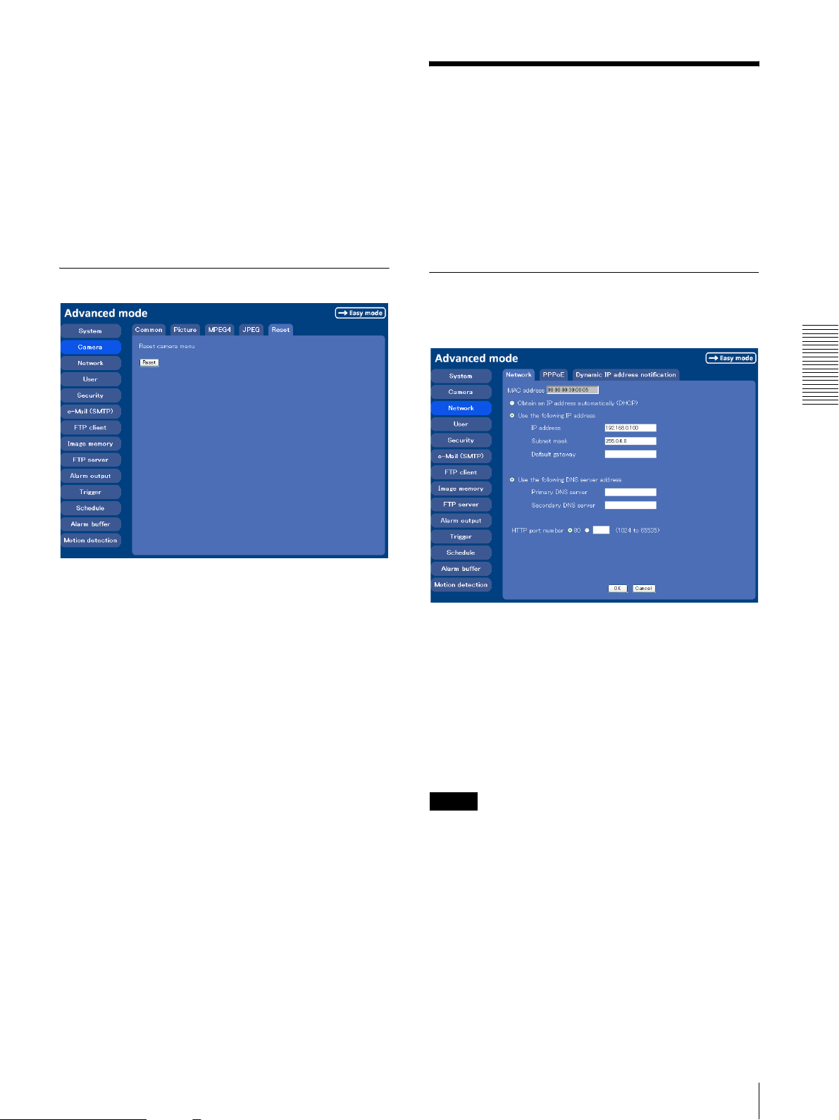
JPEG Tab
Frame rate
Set the maximum frame rate of JPEG image that can be
monitored on the computer. Selectable frame rates are 5,
6, 8, 10, 15, 20, 25 and 30 fps.
Image quality
Set the quality of JPEG image.
Selectable values are from Level 1 to Level 5.
Selecting level 5 gives the image with the highest
quality.
32
Setting the Camera Image and Audio — Camera setting Menu
Page 33
Bandwidth control
When the video mode is set to JPEG, the network
bandwidth can be limited. Selectable bandwidths are
0.5, 0.6, 0.7, 0.8, 0.9, 1.0, 2.0, 3.0, 4.0, and Unlimited
Mbps. When you do not wish to limit the bandwidth,
select Unlimited.
OK/Cancel
See “Buttons common to every setting menu” on page
25.
Configuring the Network
— Network setting Menu
When you click Network on the Advanced mode menu,
the Network setting menu appears.
Use this menu to configure the network to connect the
camera and the computer.
The Network setting menu consists of 3 tabs: Network,
PPPoE and Dynamic IP address notification.
Reset Tab
Reset camera menu
Click Reset, and the message “Camera menu setting is
reset to default. Are you sure?” is displayed. To reset to
default, click OK.
Network Tab
This section provides the menus for connecting the
camera through the network cable.
Administrating the Camera
MAC address
Displays the MAC address of the camera.
Obtain an IP address automatically
(DHCP)
DHCP server is installed on the network. Select it when
the IP address is assigned by DHCP server. IP address is
assigned automatically.
Note
When you set Obtain an IP address automatically
(DHCP), make sure that DHCP server is working on the
internet.
Use the following IP address
Select this when a fixed IP address is set.
IP address
Type the IP address of the camera.
Configuring the Network — Network setting Menu
33
Page 34
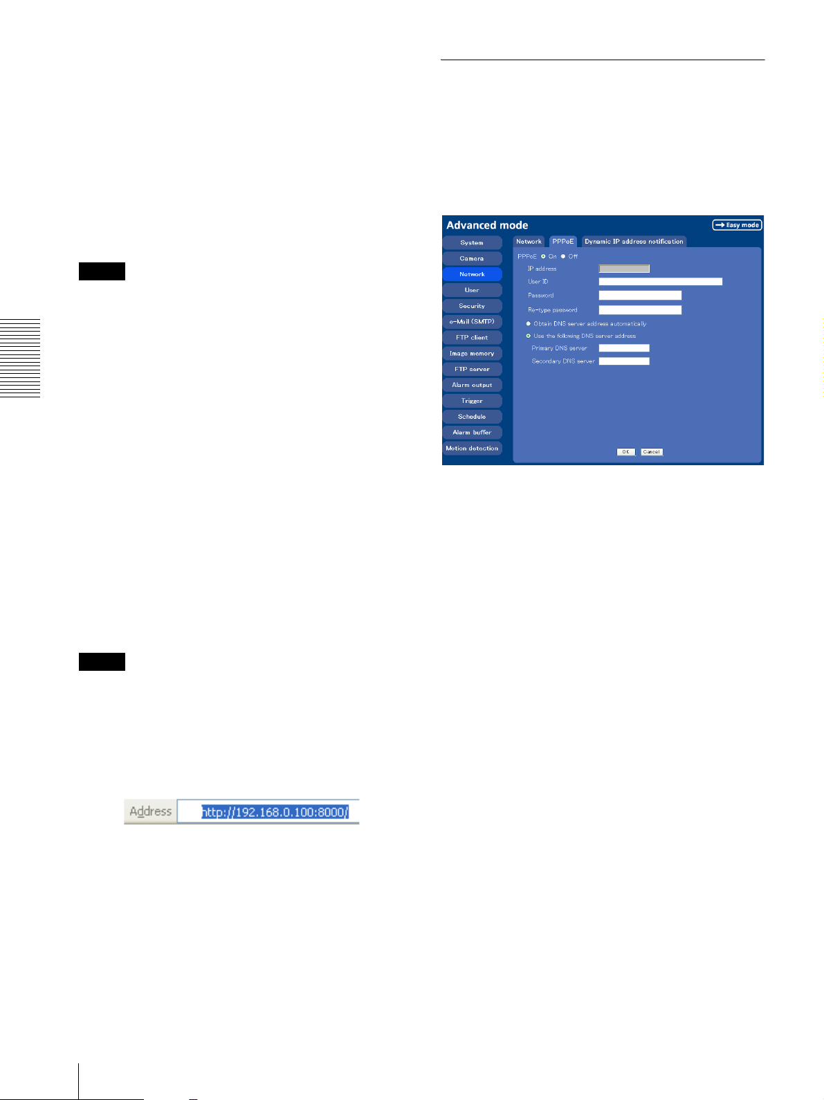
Subnet mask
Type the subnet mask.
PPPoE Tab - Setting of PPPoE Connection
Default gateway
Type the default gateway.
Obtain DNS server address automatically
Select this to obtain the address of DNS server
automatically. It can be set only when Obtain an IP
address automatically (DHCP) is selected.
Note
When you select “Obtain DNS server address
automatically”, make sure that DHCP server is active on
the network.
Use it when you connect the camera with PPPoE (Pointto-Point Protocol over Ethernet). PPPoE connection is
the protocol that is widely used in xDSL (digital affiliate
line such as ADSL, VDSL or SDSL) as the
authentication and connection system.
Use the following DNS server address
Select this when you set the fixed address as the IP
Administrating the Camera
address of DNS server.
Primary DNS server
Type the IP address of the primary DNS server.
Secondary DNS server
Type the IP address of the secondary DNS server, if
necessary.
PPPoE
Set whether you connect the camera using PPPoE
function or not. When On is selected, PPPoE connection
is used.
HTTP port number
Normally select 80. If you want to use a port number
other than 80, select the text box and type a port number
between 1024 and 65535.
Note
When you have set the HTTP port number to a number
other than 80 on the Network setting page or in the Setup
Program, access the camera by typing the IP address of
the camera on the web browser, as follows:
Example: when HTTP port number is set to 8000
OK/Cancel
See “Buttons common to every setting menu” on page
25.
IP address
When you connect to the network by PPPoE function, IP
address obtained at PPPoE connection is displayed.
User ID
Type the user ID for the authentication necessary for
PPPoE connection. Type up to 64 characters.
Password
Type the password for the authentication necessary for
PPPoE connection. Type comfirm from 1 to 32
characters.
Re-type password
To comfirm the password, re-type the password typed in
the password box.
Obtain DNS server address automatically
Select to obtain the address of DNS server
automatically.
Use the following DNS server address
Select to set the fixed address as the IP address of DNS
server.
34
Configuring the Network — Network setting Menu
Page 35

Primary DNS server
Type the IP address of the primary DNS server.
Dynamic IP address notification
Tab — Notifying the IP Address
Secondary DNS server
Type the IP address of the secondary DNS server.
OK/Cancel
See “Buttons common to every setting menu” on page
25.
When the DHCP setting is set to On or PPPoE setting is
set to On on the Network tab, you can send notification
of the completion of the network settings using the
SMTP or HTTP protocol.
Administrating the Camera
e-Mail (SMTP) notification
Select On to send an e-Mail when the DHCP setting is
completed.
SMTP server name
Type the name or IP address of the SMTP server to use
for sending an e-Mail, up to 64 characters.
Authentication
Select the authentication required when you send an eMail.
None: Select if no authentication is required when an e-
Mail is sent.
SMTP authentication: Select if authentication is
required if an e-Mail is sent.
POP before SMTP: Select if POP before SMTP is
required when an e-Mail is sent.
POP server name
It is necessary when the POP before SMTP is selected
in Authentication.
Type the POP (receiving mail) server name up to 64
characters. Or type the IP address of the POP server.
This setting is necessary when the SMTP server which
sends e-Mails performs authentication using the POP
user account.
User name, Password
Type the user name and Password of the user who has
the mail account. This setting is necessary when the
SMTP server which sends e-Mails performs
authentication.
Configuring the Network — Network setting Menu
35
Page 36
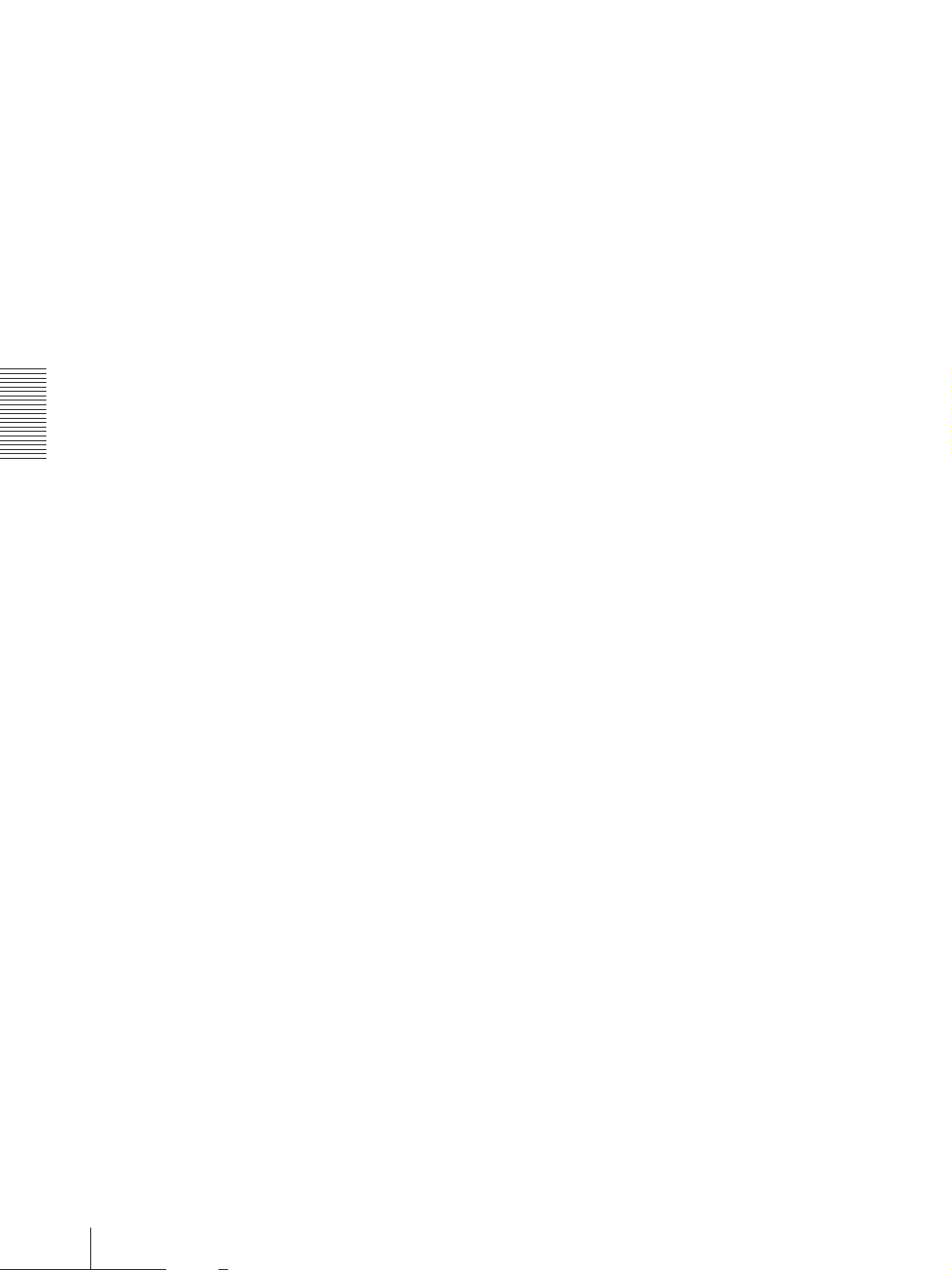
Recipient e-Mail address
Type the recipient e-Mail address up to 64 characters.
You can specify only one recipient e-Mail address.
OK/Cancel
See “Buttons common to every setting menu” on page
25.
Administrator e-Mail address
Type the e-Mail address of the camera administrator, up
to 64 characters. This is used as the reply address or the
address for a system mail from the mail server.
Subject
Type the subject/title of the e-Mail up to 64 characters.
Message
Type the text of the e-Mail up to 384 characters. (A line
break is equivalent to 2 characters.) You can describe
the information of the acquired IP address, etc. using the
special tags mentioned below.
Administrating the Camera
HTTP notification
Select On to output a command to the HTTP server
when the DHCP setting is completed. Using this
function, you can configure a useful system, for
example, to view the access log stored in the HTTP
server or start an external CGI program.
URL
Specify the URL to send HTTP commands, up to 256
characters. The URL is normally composed as follows:
http://ip_address[:port]/path?parameter
About the special tags
You can use the following five special tags to allow the
notification of the settings acquired by the DHCP, such
as an IP address. Type the tags in the parameter section
of the URL that you described in the Message field of
the HTTP.
<IP>
Use this tag to embed the IP address acquired by the
DHCP in the text or parameter.
<HTTPPORT>
Use this tag to embed the specified HTTP server port
number in the text or parameters.
<MACADDRESS>
Use this tag to embed the MAC address of the interface
whose IP address you have acquired by the DHCP, in the
text or parameter.
<MODELNAME>
Use this tag to embed the camera's model name (SNCP1) in the text or parameter.
<SERIAL>
Use this tag to embed the camera's serial number in the
text or parameter.
ip_address: Type the IP address or host name of the host
to which you want to connect.
:port: Specify the port number to which you want to
connect. If you want to use the well-known port
number 80, you do not need to input this value.
path: Type the command name.
parameter: Type the command parameter if necessary.
You can use the special tags mentioned below for the
parameters.
Proxy server name
When you send HTTP commands via a proxy server,
type the name or IP address of the proxy server, up to 64
characters.
Proxy port number
Specify the port number when you send HTTP
commands via the proxy server. Set a port number
between 1024 and 65535.
Method
Select the HTTP method GET or POST.
36
Configuring the Network — Network setting Menu
Page 37
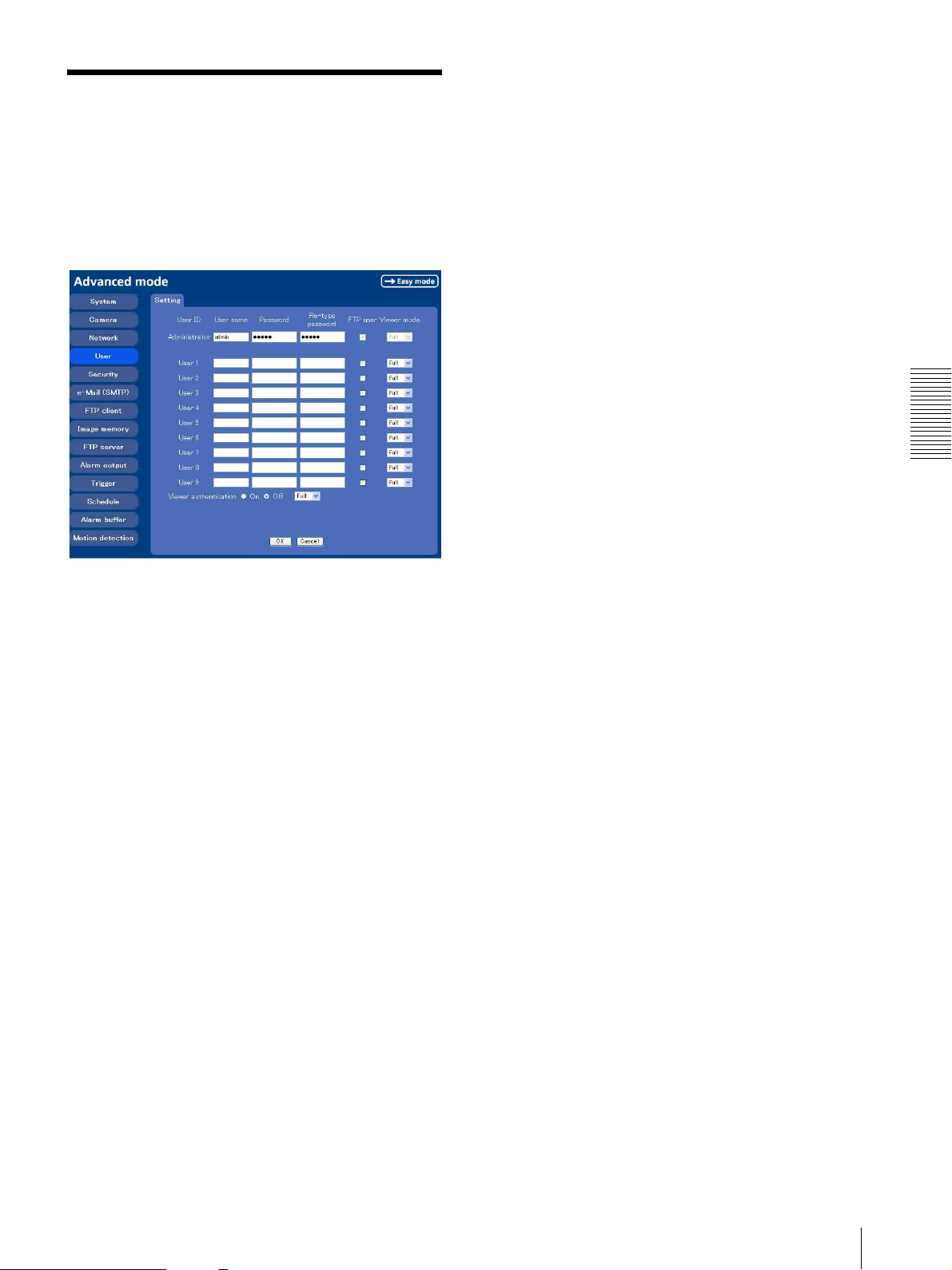
Setting the User
— User setting Menu
When you click User on the Advanced mode menu, the
User setting menu appears.
Use this menu to set the user names and passwords of
Administrator and up to 9 kinds of users (User 1 to User
9), and the access right of each user.
Viewer authentication
Set whether the user is authenticated or not when the
main viewer is displayed.
When you select On, the main viewer is displayed to suit
the authenticated user. When you select Off, select the
view mode of the main viewer page which is displayed
without authentication from Full, Light or View.
OK/Cancel
See “Buttons common to every setting menu” on page
25.
Administrating the Camera
Administrator, User 1 to 9
Specify User name, Password, Re-type password,
FTP user and Viewer mode for each user ID.
User name
Type a user name between 5 and 16 characters.
Password
Type a password between 5 and 16 characters.
Re-type password
To confirm the password, retype the password typed in
the Password box.
FTP user
Set whether allowed to log in to FTP server or not.
Check the box if allowed to log in to FTP server.
Viewer mode
If the user is authenticated when the main viewer is
displayed, you can select the viewer mode displayed
after authentication.
Full: You can operate all functions in this mode.
Light: You can operate the functions other than the
trigger button on the main viewer, TCP/UDP
switching button on the main viewer, and the frame
rate setting.
View: You can only monitor the camera image.
Setting the User — User setting Menu
37
Page 38
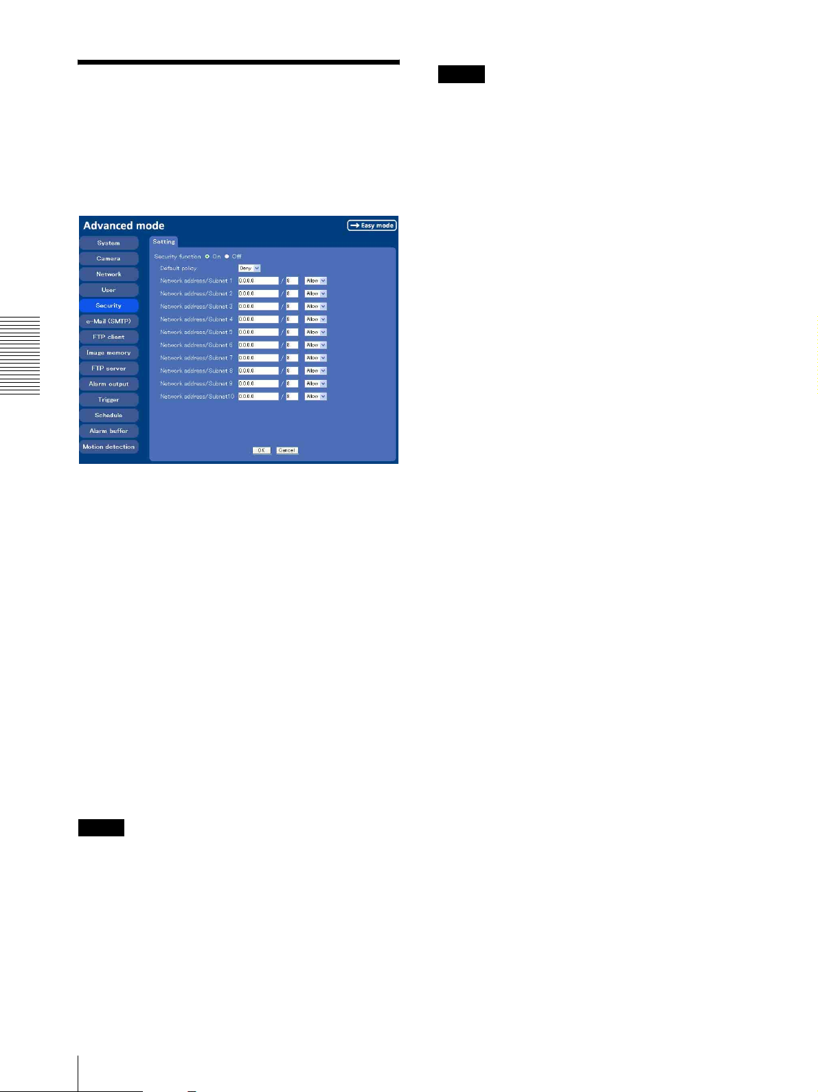
Note
Setting the Security
— Security setting Menu
When you click Security on the Advanced mode menu,
the Security setting menu appears.
Use this menu to limit the computers that can access the
camera.
Administrating the Camera
You can access the camera even from a computer having
an IP address whose access right is set to Deny, if you
enter the user name and password set for the
Administrator boxes in the User setting menu.
OK/Cancel
See “Buttons common to every setting menu” on page
25.
Security function
To activate the security function, select On.
If you do not wish to use the security function, select
Off.
Default policy
Select the basic policy of the limit from Allow and Deny
for the computers specified on the Network address/
Subnet 1 to Network address/Subnet 10 menus below.
Network address/Subnet 1 to Network
address/Subnet 10
Type the IP addresses and subnet mask values you want
to allow or deny access to the camera.
You can specify up to 10 IP addresses and subnet mask
values. For a subnet mask, type 8 to 32.
Select Allow or Deny from the drop-down list on the
right for each IP address/subnet mask .
Tip
The subnet mask value represents the bit number from
the left of the network address.
For example, the subnet mask value for “255.255.255.0”
is 24.
If you set “192.168.0.0/24” and “Allow,” you can allow
access from the computers having an IP address between
“192.168.0.0” and “192.168.0.255”.
38
Setting the Security — Security setting Menu
Page 39
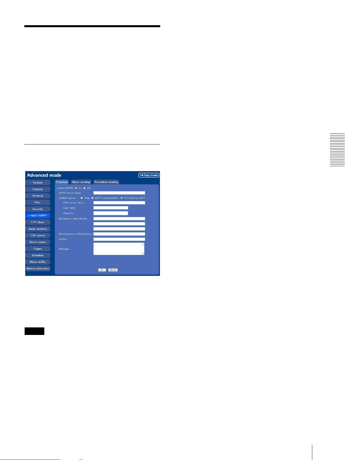
Sending an Image via
mail
Menu
When you click SMTP on the Advanced mode menu,
the SMTP setting menu appears.
By using Mail (SMTP) function, you can send a mail
with attached image which has been shot linked with the
external sensor input or with the built-in motion
detection function. The image file can also be sent
periodically.
e-Mail (SMTP) setting menu is composed of three tabs:
Common, Alarm sending and Periodical sending.
Common Tab — Setting the SMTP
Function
— e-Mail (SMTP) setting
SMTP server name
Type the SMTP server name up to 64 characters, or the
IP address of the SMTP server.
Authentication
Select the authentication required when you send an eMail.
None: Select if no authentication is required when an e-
Mail is sent.
SMTP authentication: Select if authentication is
required when an e-Mail is sent.
POP before SMTP: Select if POP before SMTP
authentication is required when an e-Mail is sent.
POP server name
It is necessary when the POP before SMTP is selected
in Authentication.
Type the POP (receiving mail) server name up to 64
characters, or type the IP address of the POP server. This
setting is necessary when the SMTP server which sends
e-mails performs authentication using the POP user
account.
User name, Password
Type the user name and Password of the user who has
the mail account. This setting is necessary when the
SMTP server which sends e-mails performs
authentication.
Administrating the Camera
e-Mail (SMTP)
Select On when you use the e-Mail (SMTP) function.
The common setting options are displayed below.
If you do not wish to use the e-Mail (SMTP) function,
select Off and click OK.
Notes
• During transmission of an image file via mail, the
frame rate and operation performance of the monitor
image of the main viewer decline.
• While the camera video mode is set to MPEG4, the
image of the composite video signal output from the
video output connector of the camera may be distorted
during mail transmission.
• You cannot send an audio file by using the mail
sending function.
Recipient e-Mail address
Type the recipient e-Mail address up to 64 characters.
You can specify up to three recipient e-Mail addresses.
Administrator e-Mail address
Type the Administrator e-Mail address up to 64
characters.
This address is used for reply mail and sending system
messages from the SMTP server.
Subject
Type the subject/title of the e-Mail up to 64 characters.
When Alarm sending of the alarm tab is set to ON, the
mail sent due to the alarm detection will indicate the
type of alarm in the subject. SI is added for sensor input
detection, and MD is added for motion detection.
Message
Type the text of the e-Mail up to 384 characters. (A line
break is equivalent to 2 characters.)
OK/Cancel
See “Buttons common to every setting menu” on page
25.
Sending an Image via mail — e-Mail (SMTP) setting Menu
39
Page 40
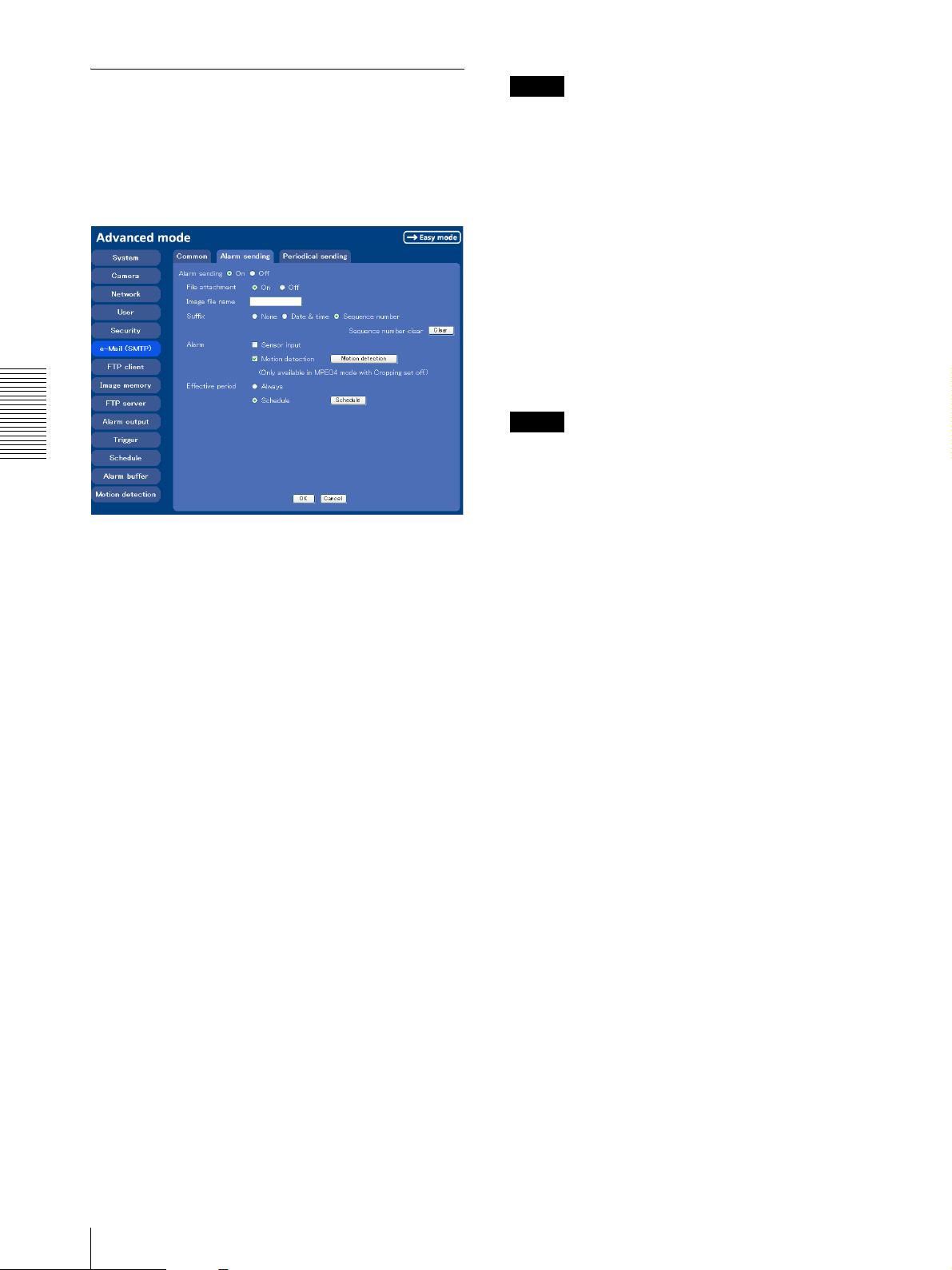
Alarm sending Tab — Setting the
mail sending mode when detecting
the alarm
Set to send the mail with connection to the alarm
detection by the external sensor input or by the built-in
motion detection function.
Tip
A consecutive number added to Date & time and
Sequence number is used to identify each of multiple
files created with one alarm event.
Sequence number clear
Click Clear to reset the Sequence number suffix to 1.
Alarm
Select the connected alarm.
Sensor input: The external sensor which is connected to
the sensor input of the camera I/O port.
Motion detection: Click Motion detection button, and
the Motion detection setting menu is displayed. You
can set the motion detection function (page 52).
Note
Motion detection works only when the camera Video
Administrating the Camera
mode is set to MPEG4 and the Cropping is set Off.
Effective period
Alarm sending
Select On to set to send mail with connection to the
alarm detection.
File attachment
Set whether an image file is to be attached to the mail or
not.
When On is selected, the image file made by the settings
below is attached. When Off is selected, only the
message is sent.
Set the period when the alarm detection is effective.
Always: The alarm detection is always effective.
Schedule: You can specify the period when the alarm
detection is effective in the schedule setting in the
other section.
Click Schedule and the setting menu for the
Effective period is displayed. (“Setting the Schedule
— Schedule setting Menu” on page 51)
OK/Cancel
See “Buttons common to every setting menu” on page
25.
Image file name
Type the file name you want to assign to the image to
attach a mail. You can use up to 10 alphanumeric, (hyphen) and _ (underscore) for naming.
Suffix
Select a suffix to add to the file name.
None: No suffix is added. The Image file name is
assigned to the image to be sent via an e-Mail.
Date & time: The date & time suffix is added to the
Image file name.
The date/time suffix consists of lower two-digits of
year (2 digits), month (2 digits), date (2 digits), hour
(2 digits), minute (2 digits), second (2 digits), and
consecutive number (2 digits), thus 14-digit number
is added to the file name.
Sequence number: A consecutive number of 10 digits
between 0000000001 and 4294967295 and two fixed
digits 00 is added to the Image file name.
40
Sending an Image via mail — e-Mail (SMTP) setting Menu
Page 41
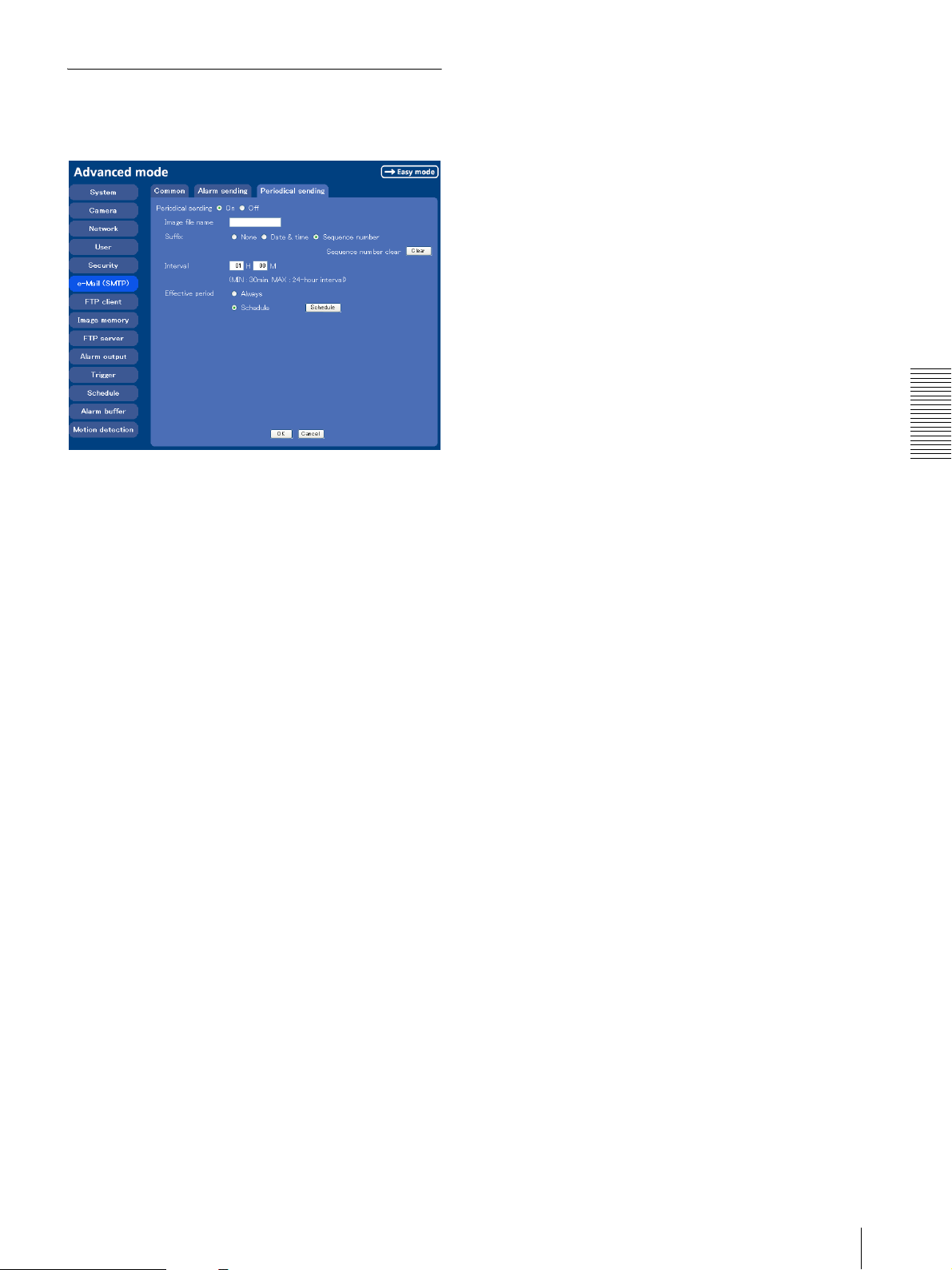
Periodical sending Tab — Setting
the periodical mail sending mode
You can set to send mails periodically.
Effective period
Set the period when the periodical sending is effective.
Always: The periodical sending is always effective.
Schedule: You can specify the period when the
periodical sending is effective in the schedule setting
in the other section.
Click Schedule and the setting menu for the effective
period is displayed. (“Setting the Schedule —
Schedule setting Menu” on page 51)
OK/Cancel
See “Buttons common to every setting menu” on page
25.
Periodical sending
Select On when you want to send mails periodically. If
you select Off, Periodical sending is not executed.
Image file name
Type the file name of the image attached to the mail up
to 10 alphanumeric, - (hyphen) and _ (under score).
Suffix
Select a suffix added to the file name used when the mail
is sent.
None: The name of the sent file will be the Image file
name.
Date & time: The date & time suffix is added to the
Image file name.
The date & time suffix consists of lower two-digits of
year (2 digits), month (2 digits), date (2 digits), hour
(2 digits), minute (2 digits) and second (2 digits), and
consecutive number (2 digits), thus 14-digit number
is added to the file name.
Sequence number: A consecutive number of 10 digits
between 0000000001 and 4294967295 and two fixed
digits 00 is added to the Image file name.
Administrating the Camera
Sequence number clear
Click Clear and the suffix of the sequence number
returns to 1.
Interval
Type the interval at which you want to send a mail
periodically. You can set the hour (H) and minutes (M)
between 30 minutes and 24 hours (one day).
Sending an Image via mail — e-Mail (SMTP) setting Menu
41
Page 42
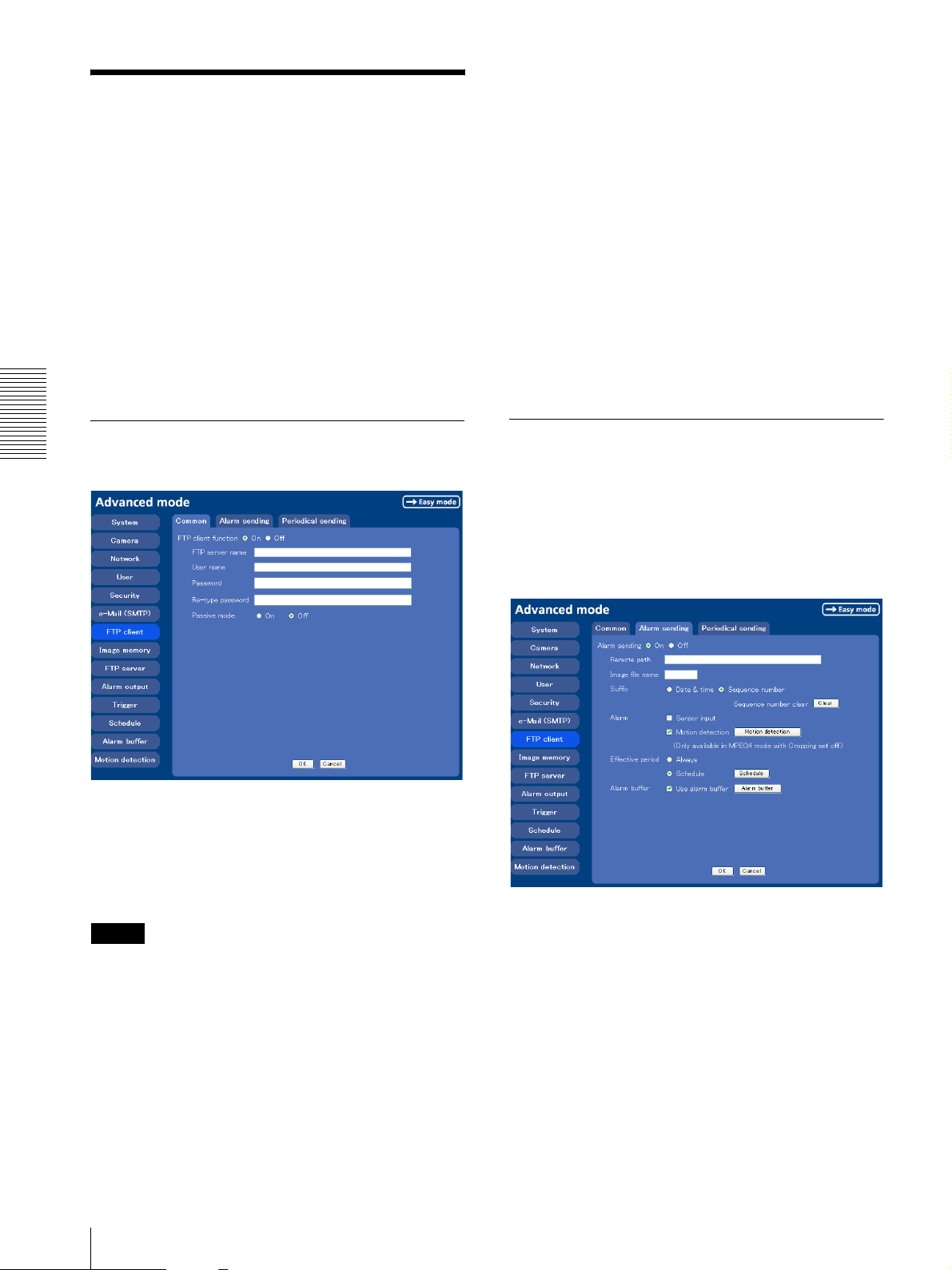
Sending Images to FTP
Password
Type the password for the FTP server.
Server
— FTP client setting Menu
When you click FTP client on the Advanced mode
menu, the FTP client setting menu appears.
Use this menu to set up for capturing and sending still
images to an FTP server. By using FTP client function,
you can send the image and audio file which has been
shot and recorded linked with the external sensor input
or with the built-in motion detection function to FTP
server. The image file can also be sent periodically.
FTP client setting menu is composed of three tabs
Common, Alarm sending and Periodical sending.
Common Tab — Setting the FTP
Administrating the Camera
Client Function
Re-type password
To confirm the password, type the same characters as
you typed in the Password box.
Passive mode
Set whether you use the passive mode of FTP server or
not when connecting to FTP server. Select On to
connect to FTP server using the passive mode.
OK/Cancel
See “Buttons common to every setting menu” on page
25.
Alarm sending Tab — Setting the
FTP client action when detecting
the alarm
Set to forward the image and audio file to the specified
FTP server linked with the alarm detection by the
external sensor input or by the built-in motion detection
function.
FTP client function
To activate the FTP client function, select On. The FTP
client setting page appears.
When you do not wish to use the FTP client function,
select Off.
Note
The frame rate and operability on the main viewer may
decrease while a file is being transmitted by the FTP
client function.
FTP server name
Type the FTP server name to upload still images up to 64
characters, or the IP address of the FTP server.
User name
Type the user name for the FTP server.
42
Sending Images to FTP Server — FTP client setting Menu
Alarm sending
Select On to send the image and audio file to FTP server
linked with the alarm detection.
Remote path
Type the path to the destination up to 64 characters.
Image file name
Type the file name you want to assign to the images
when sending to the FTP server. You can use up to 10
alphanumeric characters, - (hyphen) and _ (underscore)
for naming.
Page 43
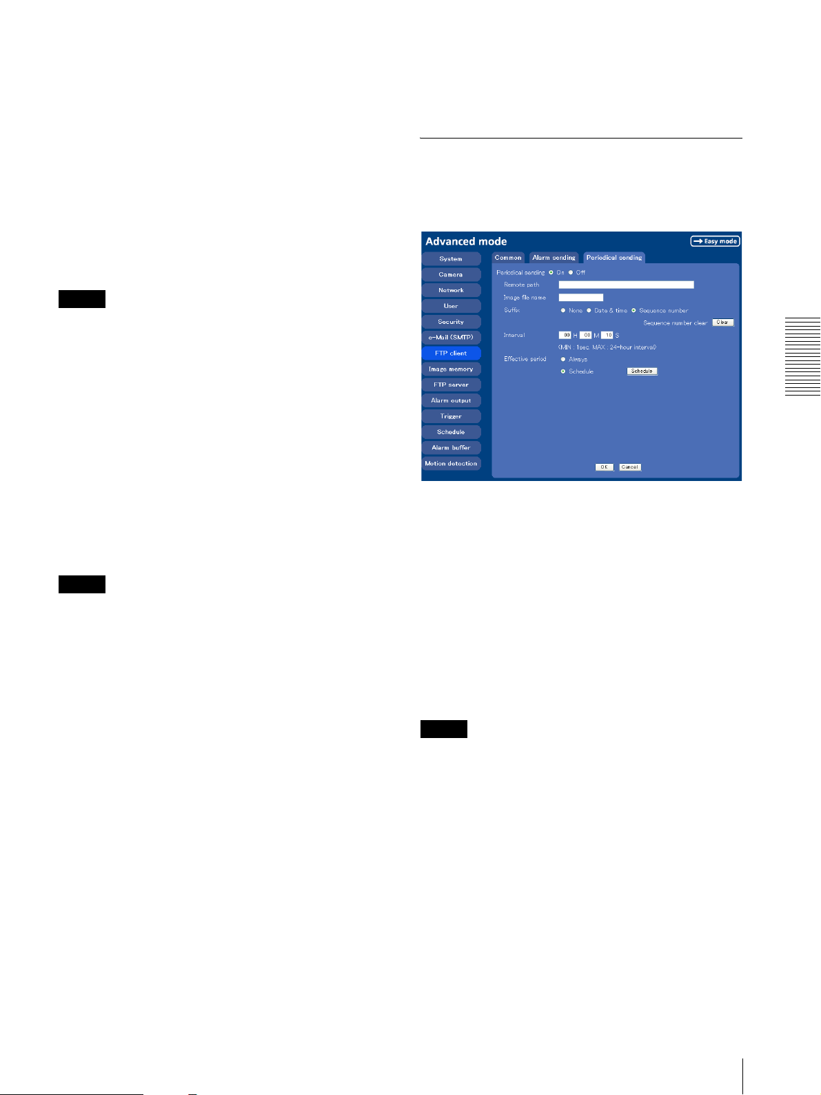
Suffix
Select a suffix to add to the file name.
Date & time: The date & time suffix is added to the
Image file name.
The date/time suffix consists of lower two-digits of
year (2 digits), month (2 digits), date (2 digits), hour
(2 digits), minute (2 digits) and second (2 digits), and
consecutive number (2 digits), thus 14-digit number
is added to the file name.
Sequence number: A consecutive number of 10 digits
between 0000000001 and 4294967295 and an
consecutive 2 digits number is added to the Image
file name.
Tip
A consecutive number added to Date & time and
Sequence number is used to identify each of multiple
files created with one alarm event.
OK/Cancel
See “Buttons common to every setting menu” on page
25.
Periodical sending Tab — Setting
the Periodical FTP Client Activity
You can set to send an image file to FTP server
periodically.
Sequence number clear
Click Clear to reset the Sequence number suffix to 1.
Alarm
Select the connected alarm.
Sensor input: The external sensor which is connected to
the sensor input of the camera I/O port.
Motion detection: Click Motion detection button, and
the Motion detection setting menu is displayed. You
can set the motion detection function (page 53).
Note
Motion detection works only when the Video mode is
set to MPEG4 and the Cropping is set to Off.
Effective period
Set the period when the alarm detection is effective.
Always: The alarm detection is always effective.
Schedule: You can specify the period when the alarm
detection is effective in the schedule setting in the
other section.
Click Schedule and the setting menu for the
Effective period is displayed. (“Setting the Schedule
— Schedule setting Menu” on page 51)
Alarm buffer
Select Use alarm buffer when you forward the image/
audio of before and after the alarm detection (pre-alarm,
post-alarm).
If you do not select it, only the image of the moment of
the alarm detection is forwarded.
Click Alarm buffer to display the Alarm buffer setting
menu.
For details, see “Setting the Alarm Buffer — Alarm
buffer setting Menu” on page 51.
Administrating the Camera
Periodical sending
Select On when you want to use periodical sending. If
you select Off, Periodical sending is not executed.
Remote path
Type the remote path up to 64 characters.
Image file name
Type the file name of the image sent to FTP server up to
10 alphanumeric characters, - (hyphen) and _ (under
score).
Note
You cannot send the audio file by using the periodical
sending function of FTP.
Suffix
Select a suffix to be added to the file name sent to FTP
server.
None: The name of the sent file will be the Image file
name.
Date & time: The date & time suffix is added to the
Image file name.
The date & time suffix consists of lower two-digits of
year (2 digits), month (2 digits), date (2 digits), hour
(2 digits), minute (2 digits) and second (2 digits), and
consecutive number (2 digits), thus 14-digit number
is added to the file name.
Sending Images to FTP Server — FTP client setting Menu
43
Page 44
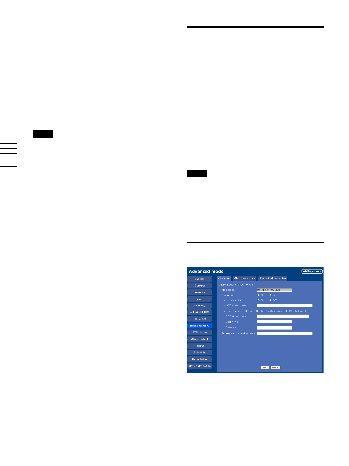
Sequence number: A consecutive number of 10 digits
between 0000000001 and 4294967295 and two fixed
digits 00 is added to the Image file name.
Recording Images in
Memory
Sequence number clear
Click Clear and the suffix of the sequence number
returns to 1.
Interval
Type the interval at which you want to send images to
the FTP server periodically. You can set the hour (H),
minutes (M) and seconds (S) between 1 second and 24
hours (one day).
Note
The actual interval may be longer than the set value,
depending on the image size, image quality setting, bit
rate and the network environments.
Administrating the Camera
Effective period
Set the period when the periodical sending is effective.
Always: The periodical sending is always effective.
Schedule: You can specify the period when the
periodical sending is effective in the schedule setting
in the other section.
Click Schedule and the setting menu for the effective
period is displayed. (“Setting the Schedule —
Schedule setting Menu” on page 51)
— Image memory setting Menu
When you click Image memory on the Advanced mode
menu, the Image memory setting menu appears.
By using the image memory function, you can record the
image and audio file, which has been shot being linked
with the external sensor input or with the built-in motion
detection function, to the built-in memory (about 8 MB)
of the camera. The image file can also be recorded
periodically.
You can also record a still image periodically.
The recorded image and audio files can be found or
downloaded to the computer using the FTP server
function. (See “Sending an Image via mail — e-Mail
(SMTP) setting Menu” on page 39.)
Image memory setting menu is composed of three tabs
Common, Alarm recording and Periodical recording.
Notes
• The image and audio files recorded in the built-in
memory will be erased when the power of the camera
is turned off.
• The frame rate and operability on the main viewer
may decrease during image storage in the built-in
memory.
• When the Overwrite is set to On, a warning mail is not
sent to the Administrator.
OK/Cancel
See “Buttons common to every setting menu” on page
25.
Common Tab — Setting the Image
memory Function
Image memory
Set whether you use the Image memory function or not.
When you select On, the Common setting options are
displays in the below. If you do not use it, select Off and
click OK.
44
Recording Images in Memory — Image memory setting Menu
Page 45
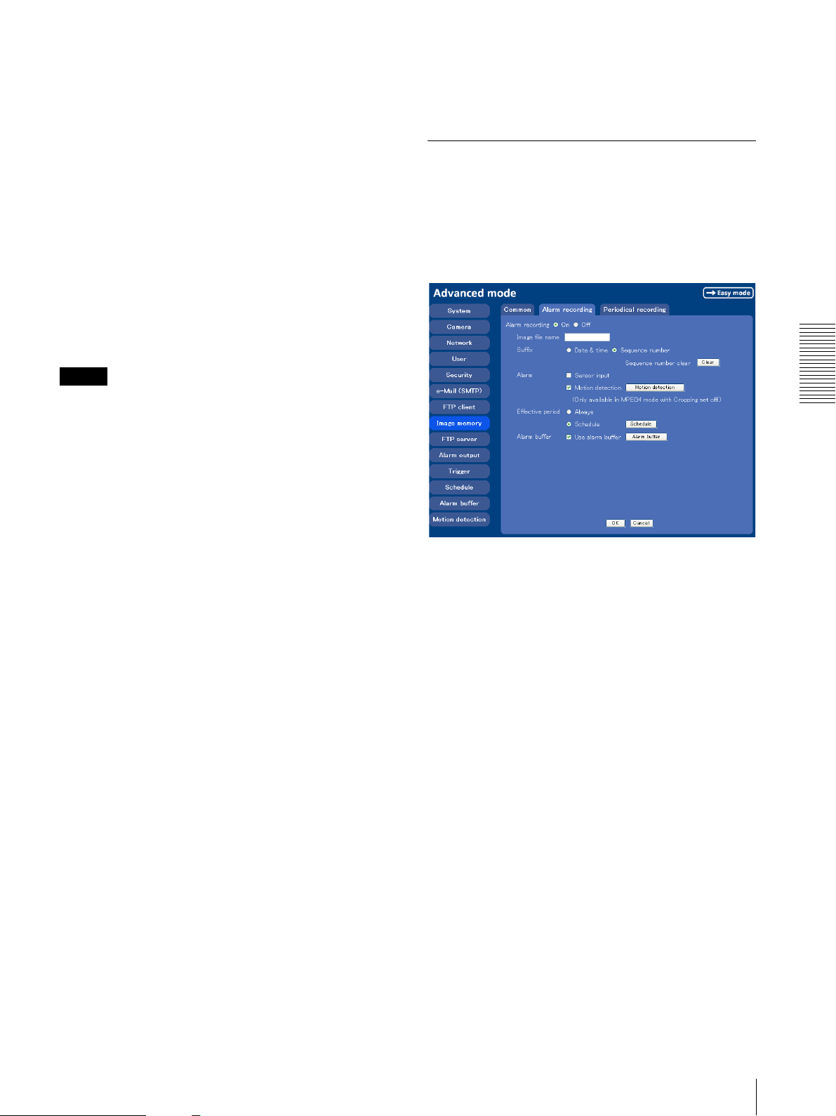
Free space
Shows the current free space of the builtin memory.
Overwrite
Select to overwrite the file or not when there is
insufficient memory space to record the image.
Select On to allow overwriting. The oldest file or folder
is overwritten first.
Select Off to prohibit overwriting. In this case, a new
file cannot be stored.
Capacity warning
Select On to send a warning mail to the Administrator
when the built-in memory space is low or the memory is
full. Select Off if you do not want to send a warning
mail.
Note
OK/Cancel
See “Buttons common to every setting menu” on page
25.
Alarm recording Tab — Setting the
Image Memory Function when
Detecting the Alarm
You can set to record the image and audio file to the
built-in memory linked with the external sensor input or
with the built-in motion detection function.
When the Overwrite is set to On, a warning mail is not
sent to the Administrator.
SMTP server name
Type the name of the SMTP server to use for sending an
e-Mail, up to 64 characters.
Otherwise type the IP address of SMTP mail server.
Authentication
Select the authentication required if you send a mail.
None: Select if no authentication is required when an e-
mail is sent.
SMTP authentication: Select if authentication is
required when an e-Mail is sent.
POP before SMTP: Select if POP before SMTP
authentication is required when an e-Mail is sent.
POP server name
This is necessary when POP before SMTP is selected
in Authentication.
Type POP (receiving mail) server name up to 64
characters. Otherwise type the IP address of POP server.
This setting is necessary when SMTP server that sends a
mail authenticates using the account of POP user.
User name, password
Type the user name and the password of the user who
has the mail account. This setting is necessary when
SMTP server that sends a mail authenticates.
Administrator e-Mail address
Type the e-Mail address of the recipient of the warning
mail (e-Mail address of the camera Administrator), up to
64 characters.
Administrating the Camera
Alarm recording
Select On to set to record the image and audio file to the
built-in memory linked with the external sensor input or
with the built-in motion detection function.
Image file name
Type the file name you want to assign to the images
when saving in the built-in memory. You can use up to
10 alphanumeric characters, - (hyphen) and _
(underscore) for naming.
Suffix
Select a suffix to add to the file name.
Date & time: The Date & time suffix is added to the
Image file name.
The Date & time suffix consists of lower two-digits
of year (2 digits), month (2 digits), date (2 digits),
hour (2 digits), minute (2 digits), second (2 digits)
and consecutive number (2 digits), thus 14-digit
number is added to the file name.
Sequence number: A consecutive number of 10 digits
between 0000000001 and 4294967295 and an
consecutive 2 digits number is added to the Image
file name.
Recording Images in Memory — Image memory setting Menu
45
Page 46
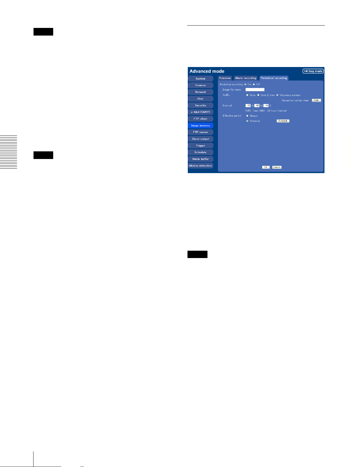
Tip
A consecutive number added to Date & time and
Sequence number is used to identify each of multiple
files created with one alarm event.
Periodical recording Tab — Setting
the Periodical recording mode
You can set to record the image file to the built-in
memory periodically.
Sequence number clear
Click Clear to reset the Sequence number suffix to 1.
Alarm
Select the connected alarm.
Sensor input: The external sensor which is connected to
the sensor input of the camera I/O port.
Motion detection: Click Motion detection button, and
the Motion detection setting page is displayed. You
can set the motion detection function (page 53).
Note
Motion detection works only when the Video mode is
Administrating the Camera
set to MPEG4 and the Cropping is set to Off.
Effective period
Set the period when the alarm detection is effective.
Always: The alarm detection is always effective.
Schedule: You can specify the period when the alarm
detection is effective in the schedule setting in the
other section.
Click Schedule and the setting menu for the effective
period is displayed. (“Setting the Schedule —
Schedule setting Menu” on page 51)
Alarm buffer
Select Use alarm buffer when you forward the image/
audio of before and after the alarm detection (pre-alarm,
post-alarm).
If you do not select it, only the image of the moment of
the alarm detection is forwarded.
Click Alarm buffer to display the Alarm buffer setting
menu.
For details, see “Setting the Alarm Buffer — Alarm
buffer setting Menu” on page 51.
OK/Cancel
See “Buttons common to every setting menu” on page
25.
Periodical recording
Select On when you want to use periodical recording. If
you select Off, the Periodical recording is not executed.
Image file name
Type the file name of the image recorded to the built-in
memory up to 10 alphanumeric, - (hyphen) and _ (under
score).
Note
You cannot send the audio file by using the periodical
recording function.
Suffix
Select a suffix to add to the file name.
None: The recording file name will be the Image file
name.
Date & time: The date & time suffix is added to the
Image file name.
The date/time suffix consists of lower two-digits of
year (2 digits), month (2 digits), date (2 digits), hour
(2 digits), minute (2 digits), second (2 digits), and
consecutive number (2 digits), thus 14-digit number
is added to the file name.
Sequence number: A consecutive number of 10 digits
between 0000000001 and 4294967295 and two fixed
digits 00 is added to the Image file name.
46
Recording Images in Memory — Image memory setting Menu
Sequence number clear
Click Clear and the suffix of the sequence number
returns to 1.
Page 47
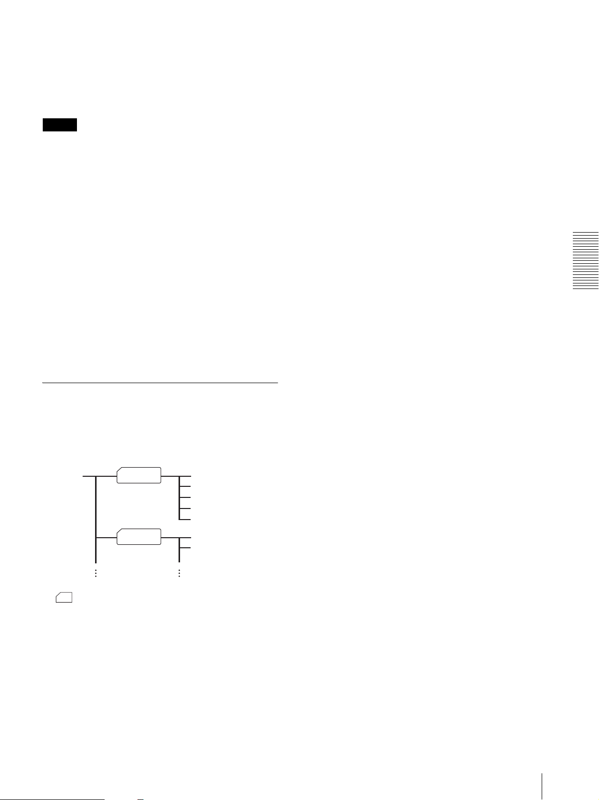
Interval
Type the interval at which you want to record an image
in the built-in memory periodically. You can set the hour
(H), minutes (M) and seconds (S) between 1 second and
24 hours (one day).
About the extension of a file
A file to be recorded/sent using the image memory
function or the FTP client function has one of the
following three extensions depending on the video mode
setting and the recording/sending settings of the camera.
Note
The actual interval may be longer than the set value,
depending on the image size or the network
environments.
Efective period
Set the period when the periodical recording is effective.
Always: The periodical recording is always effective.
Schedule: You can specify the period when the
periodical recording is effective in the schedule
setting in the other section.
Click Schedule and the setting menu for the effective
period is displayed. (“Setting the Schedule — Schedule
setting Menu” on page 51)
OK/Cancel
See “Buttons common to every setting menu” on page
25.
Directory Structure of Image Memory
.m4f: Represents the MPEG4 video mode.
.jpf: Represents the JPEG video mode when Use alarm
buffer is checked in the alarm recording/alarm
sending menu. This file includes audio data.
.jpg: Represents the JPEG video mode when Use
alarm buffer is not checked in the alarm recording/
alarm sending menu. This file can be viewed with a
normal image viewer.
The SNC video player (page 58) allows playing of
“.m4f” and “.jpf” files.
Administrating the Camera
The images are recorded in the memory with the
following directory structure.
FTP root
Date_No.
Date_No.
xxxxxxx.m4f
yyyyyyy.m4f
aaaaaaa.jpg
bbbbbbb.jpf
ccccccc.mf4
zzzzzzz.mf4
qqqqqqq.mf4
A represents a directory created automatically.
The Date_No. directory has a 7-digit name consisting of
the last two digits of year (2 digits), month (2 digits),
underscore and sequence number (2 digits).
A directory can contain video files of up to
approximately 1 MB, and a new directory will be
created automatically if the size of the video files in the
current directory exceeds the maximum size, and
recording will continue.
Recording Images in Memory — Image memory setting Menu
47
Page 48
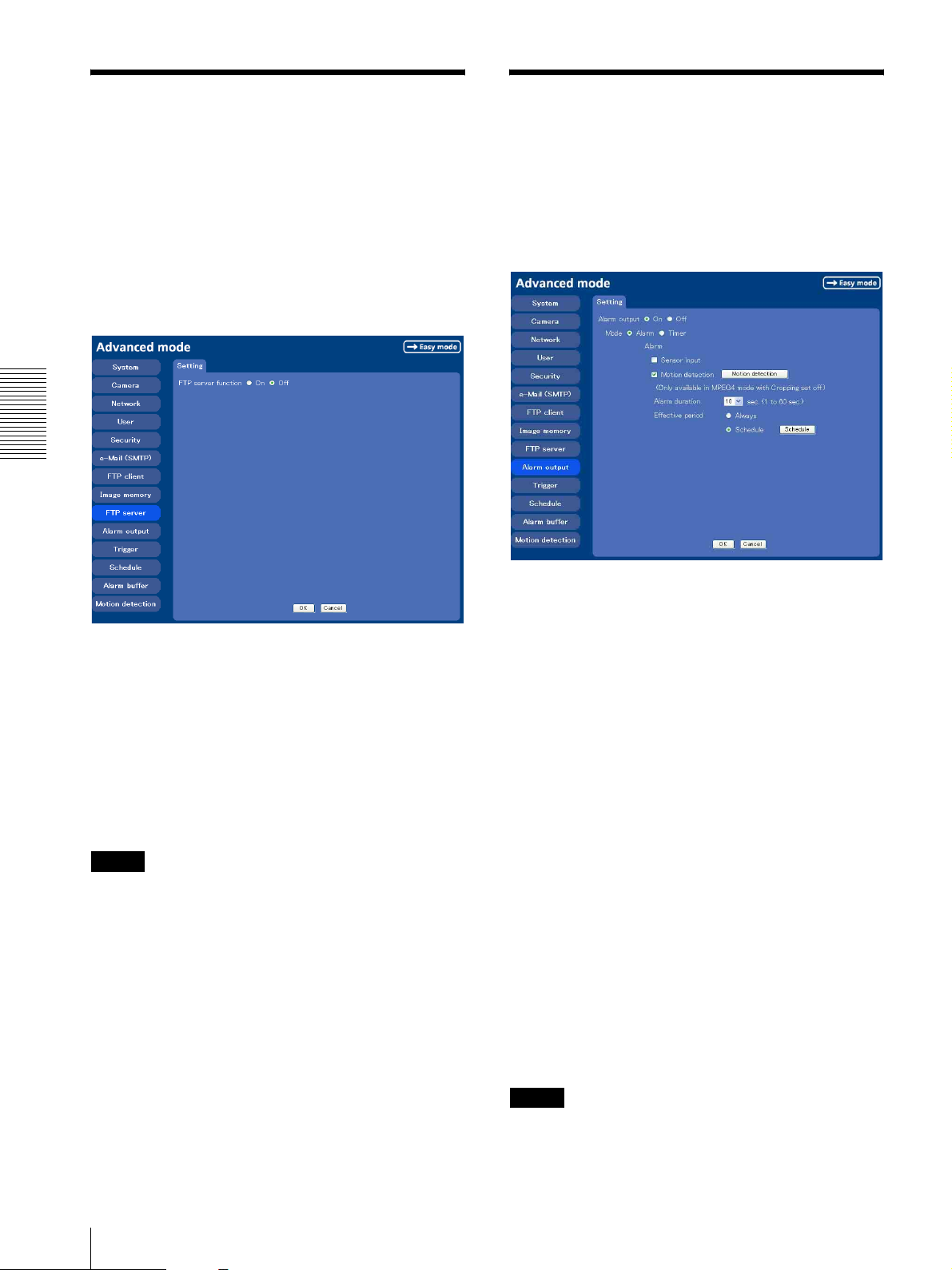
Downloading Images
Setting the Alarm Output
from the Camera
server setting Menu
When you click FTP server on the Advance mode
menu, the FTP server setting menu appears. Use this
menu to set up for the FTP server function which finds a
specified image and audio file stored in the built-in
memory of the camera (about 8 MB) or download the
still image file from the camera.
Administrating the Camera
— FTP
— Alarm output setting Menu
When you click Alarm output on the Advanced mode
menu, the Alarm output setting menu appears.
You can set in this menu to control the alarm out of I/O
port on the rear of the camera linked to the alarm
detection and the timer.
FTP server function
To activate the FTP server function, select On and click
OK.
When you do not use the FTP server function, select Off
and click OK.
OK/Cancel
See “Buttons common to every setting menu” on page
25.
Note
Note the followings when log in to FTP server of the
camera using the FTP client software on the computer.
• The frame rate and the operativity of the monitor
window in the main viewer will declime.
• While recording the image using the Image memory
function, you cannot delete the recording directory.
• When the recorded image or audio file is deleted, the
camera counts the free space of the built-in memory
again when logging off.
Alarm output
To activate the Alarm output function, select On. The
basic setting options are displayed below.
When you do not use the Alarm output function, select
Off.
Mode
Select the mode of the Alarm output function.
Alarm: Controls alarm output by synchronizing with an
external sensor input or the built-in activity detection
function.
Timer: Controls alarm output by the timer.
Alarm
This item is displayed when Mode is set to Alarm.
Select the alarm to link the alarm output function. If the
selected alarm is detected, the alarm output status
changes.
Sensor input: External sensor connected to sensor input
of the camera I/O port
Motion detection: To set the motion detection function,
click Motion detection. The Motion detection
setting page appears (see page 52).
Note
The motion detection function can activate or be set only
when the Video mode of the camera is set to MPEG4
and the Cropping is set Off.
48
Downloading Images from the Camera — FTP server setting Menu / Setting the Alarm Output — Alarm output setting Menu
Page 49
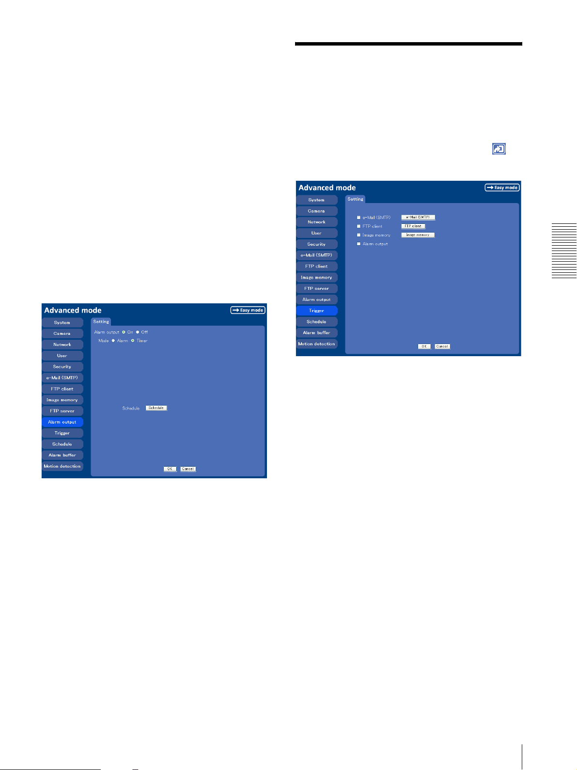
Alarm duration
Select the duration for which the alarm output is shortcircuited between 1 and 60 sec.
Effective period
This item is displayed when Mode is set to Alarm.
Set the period while the alarm detection is effective.
Always: The alarm detection is always effective.
Schedule: You can specify the period when the alarm
detection is effective in the schedule setting in the
other section.
Click Schedule and the setting menu for the effective
period is displayed. (“Setting the Schedule — Schedule
setting Menu” on page 51)
Schedule
This item is displayed when Mode is set to Timer.
Click Schedule and the setting menu for the effective
period is displayed. (“Setting the Schedule — Schedule
setting Menu” on page 51)
Setting the Operations
from the Viewer Page
Trigger setting Menu
Click Trig ger on the Advanced Mode menu to display
the Trigger Setting menu.
In this menu, you will select the activities when
Trigger icon is clicked on the main viewer.
—
Administrating the Camera
OK/Cancel
See “Buttons common to every setting menu” on page
25.
e-Mail (SMTP)
By checking this box, it will allow you to select e-Mail
in the Trigger setting menu. You can send mail with
attached image file by selecting e-Mail and clicking the
Trigger icon.
When you click e-Mail (SMTP) button, the Trig ger (e-
Mail) setting menu is displayed. You can set necessary
options here. The setting options and setting procedures
are the same as those of the e-Mail (SMTP) setting menu
(page 39).
Setting the Operations from the Viewer Page — Trigger setting Menu
49
Page 50
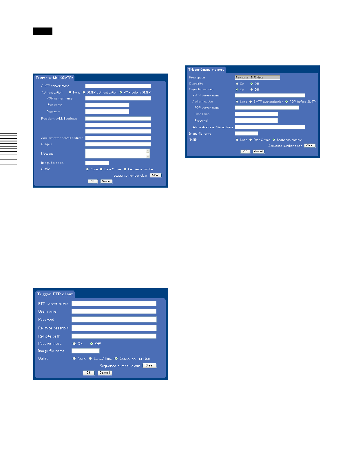
Note
While the Video mode is set to MPEG4, the image of
the composite video signal output from the video output
connector of the camera may be distorted during mail
transmission.
When you click Image memory button, the Trigger
(setting) Image memory menu is displayed. You can
set necessary options here. The setting options and
setting procedures are the same as those of the Image
Memory setting menu (page 44).
Administrating the Camera
Alarm output
By checking this box, it will allow you to select Alarm
output in the Trigger setting menu. You can control On
(short circuit ) or Off (open) by selecting Alarm output
FTP client
By checking this box, it will allow you to select FTP
client in the Trigger setting menu. You can send an
image file to FTP server by selecting FTP and clicking
the Trigger icon.
When you click FTP client button, the Trigger (setting)
FTP client menu is displayed. You can set necessary
options here. The setting options and setting procedures
are the same as those of the FTP client setting menu
(page 42).
and clicking the Trigger icon.
OK/Cancel
See “Buttons common to every setting menu” on page
25.
Image memory
By checking this box, it will allow you to select Image
memory in the Trigger setting menu. You can record an
image file to the built-in memory by selecting Image
memory and clicking the Trigger icon.
50
Setting the Operations from the Viewer Page — Trigger setting Menu
Page 51
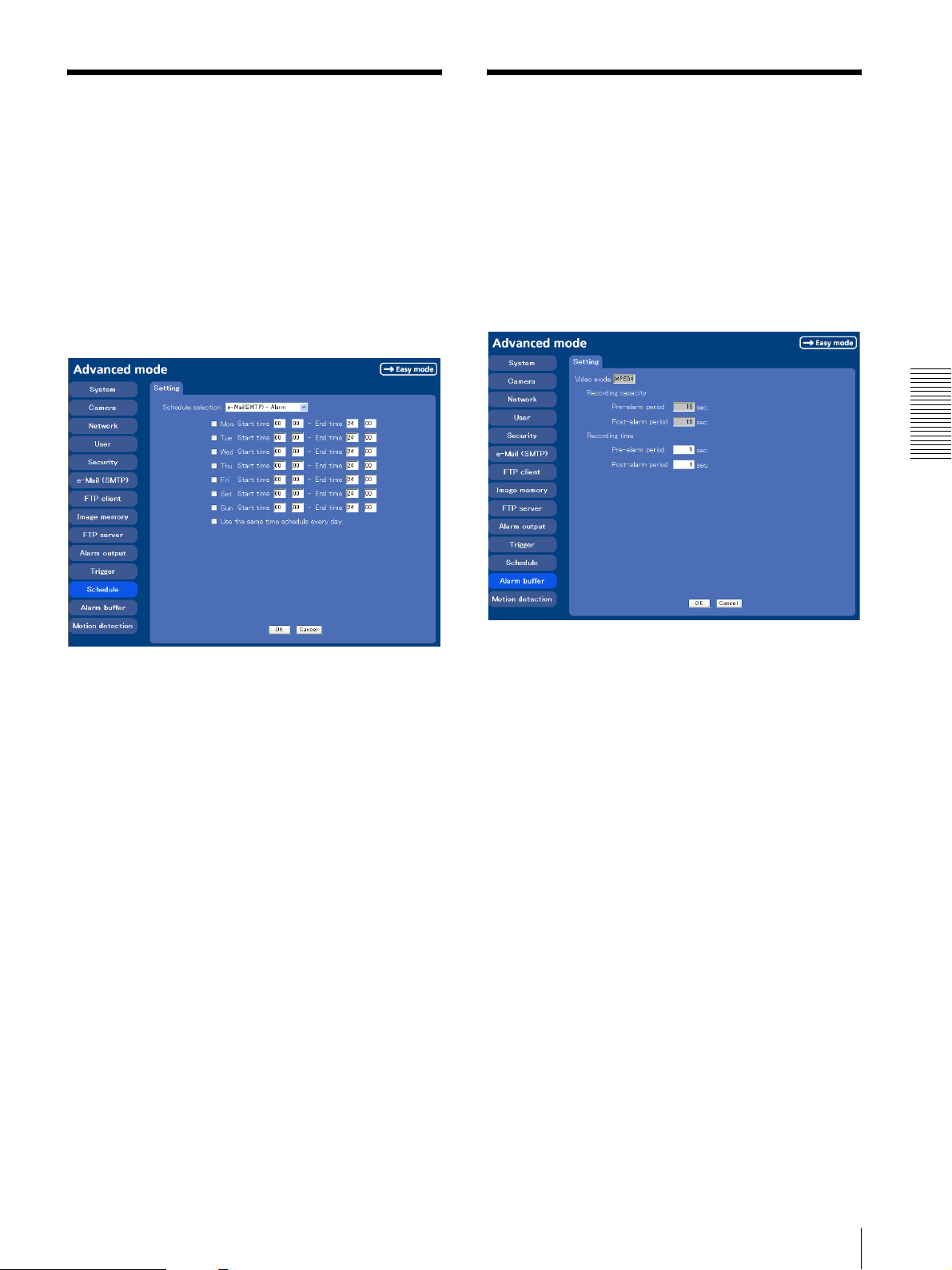
Setting the Schedule
Setting the Alarm Buffer
— Schedule setting Menu
When you click Schedule on the Advanced mode menu,
the Schedule setting menu appears.
This is the same menu as the setting menu which is
displayed when you click Schedule to set Effective
period and Schedule in FTP client setting menu, e-Mail
(SMTP) setting menu, Image memory setting menu,
Alarm out setting menu and so on.
Example: When setting e-Mail (SMTP) (the alarm
sending) in the Schedule setting menu
— Alarm buffer setting Menu
When you click Alarm buffer on the Advanced mode
menu, the Alarm buffer Setting menu appears.
You can set the Pre-alarm image and audio (the image
and audio before the alarm detection) and the Post alarm image and audio. These can be set when Alarm
sending or Alarm recording of FTP client setting menu
or Image memory setting menu is set to On, and besides
when Use alarm buffer is selected.
Administrating the Camera
Schedule selection
Select the list box to specify the schedule you want to
set. e-Mail (SMTP) – Alarm, e-Mail (SMTP) –
Periodical, FTP – Alarm, FTP – Periodical, Image
memory – Alarm, Image memory – Periodical,
Alarm output – Alarm or Alarm output – Timer can
be selected.
The time period on the right of the checked day is the
effective period of the schedule.
Mon (Monday) to Sun (Sunday)
The time period on the right of the checked day is the
effective period of the schedule.
Start time, End time
Specify the Start time and the End time.
Use the same time schedule every day
When this is checked, the Start time and End time set
to Mon (Monday) are applied to all days. In this case,
the Start time and End time of the other days than Mon
(Monday) cannot be input.
OK/Cancel
See “Buttons common to every setting menu” on page
25.
Video mode
The Video mode setting in the Common tab of the
Camera setting menu is displayed.
MPEG4: Shows the present output format of the camera
is MPEG4.
JPEG: Shows the present output format of the camera is
JPEG.
Recording capacity
Displays the maximum recording capacity of alarm
buffer in the present camera setting of the video mode,
image size, bit rate and frame rate.
Pre-alarm period: Displays the maximum recording
capacity of image/audio before the alarm detection.
Post-alarm period: Displays the maximum recording
capacity of image/audio after the alarm detection.
Recording time
Set the recording time for the Pre-alarm image/audio
and Post alarm image/audio.
Pre alarm period: Type the recording time of the
image/audio before the alarm detection.
Post alarm period: Type the recording time of the
image/audio after the alarm detection.
Setting the Schedule — Schedule setting Menu / Setting the Alarm Buffer — Alarm buffer setting Menu
51
Page 52
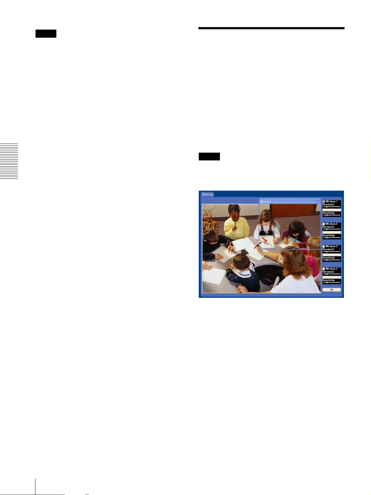
Note
The value of Recording capacity differs depending on
Image size, Bit rate (for MPEG4) and Image quality (for
JPEG) in the camera setting menu.
Setting the Motion
Detection Function
—
Motion detection setting Menu
OK/Cancel
See “Buttons common to every setting menu” on page
25.
Administrating the Camera
When you click Motion detection on the Advanced
mode menu, the Motion detection setting menu appears.
You can set the conditions to activate the built-in motion
detection function in this menu.
This is the same menu with the setting menu which is
displayed when you click Motion detection in Alarm
sending of e-Mail (SMTP) setting menu, Alarm sending
or FTP client setting menu, Alarm recording of Image
memory setting menu and so on.
Note
The motion detection function can activate or be set only
when the Video mode of the camera is set to MPEG4
and the Cropping is set Off.
52
Setting the Motion Detection Function — Motion detection setting Menu
The Motion detection setting menu is composed of the
following five parts.
Monitor display
You can monitor the moving image and set the detection
Window.
Window 1 to 4 check box
When you check it, the specified Window is displayed
on the monitor display.
Threshold slider bar
Set the Threshold level so as to judge whether there has
been any motion in the camera image or not. You can
change the Threshold level displayed in the Motion
detection indicator.
Page 53
Motion detection indicator
The moving level of the present shooting image inside
the specified Window is shown in the graph. The even
line shows the threshold level for Motion detection
which will be a guide to set the sensitivity properly.
Sensitivity slider bar
Use it to set the detection sensitivity of the monitoring
image.
When the slider bar is moved to the left end, the
sensitivity will be 0 and any motion will not be detected.
The right end is the maximum sensitivity.
Setting the Motion Detection Area, Sensitivity and Threshold level
Set the motion detection working area, the sensitivity
and the threshold level as follows:
• The Motion detection may not operate correctly in the
following cases:
– while changing a setting on the Camera setting
menu
– when the object is dark
– when the camera is installed in an unstable place
that causes vibration to the camera
– when a small bit rate (64 kbps, 128kbps) is selected
in Bit rate setting of MPEG4
1
Check Window 1 check box.
Window 1 is shown on the monitor display.
2
Settle Window 1 in the area you want to set Motion
detection.
Click and drag Window 1 to move it or change the
size of it.
3
Set the Sensitivity of Motion detection.
Adjust it referring to the level indicator of Motion
detection.
To increase the sensitivity, move the Sensitivity
slider bar to the right.
To decrease, move it to the left.
When you release the mouse, the new setting is
applied to the level of motion detection indicator.
4
Set the Threshold level of Motion detection.
Adjust the Threshold slider bar in the same way of
step 3 to set the level the camera executes motion
detection.
5
If necessary, set the Motion detection working
areas, the sensitivities and the Threshold level of
the other Windows 2, 3, 4 by following steps 1 to 4.
Administrating the Camera
6
After all settings, click OK.
Notes
• While motion detection setting menu is displayed,
motion detection of Mail (SMTP), FTP client, Image
memory and Alarm output notification will not work.
Make sure to close Motion detection setting menu
after setting.
• Before using the Motion detection, perform the
operation test to confirm correct operation.
Setting the Motion Detection Function — Motion detection setting Menu
53
Page 54
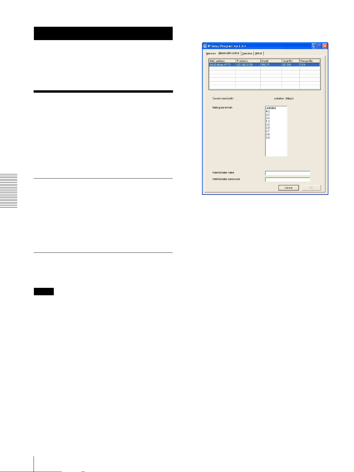
The current bandwidth is displayed in Current
Others
This section explains how to use the application
software and commands, including the supplied CDROM.
bandwidth.
Using the Supplied Setup Program
Explains the functions except the Network tab in the
Setup Program.
To install the Setup Program, to assign the IP address
and to set the network, see “Assigning the IP address to
the Camera” on page 9 in “Preparations”.
Starting the Setup Program
Select Program from Start menu of Windows, then
select Program, IP Setup Program and IP Setup
Others
Program in sequence.
The IP Setup Program starts.
Network tab appears. The IP Setup Program detects
cameras connected to the local network and lists them
on the Network tab window.
Bandwidth Control Tab
The communication bandwidth can be set when the
Video mode of the camera is set to JPEG.
Note
2
Click to select the camera to set the bandwidth from
the list box.
3
Click to select the desired bandwidth from the
Setting bandwidth list box.
4
Type t he Administrator name and Administrator
password in each box.
5
Click OK.
If “Setting OK” is displayed, the bandwidth setting
is completed.
When the Video mode of the camera is set to MPEG4,
the bandwidth cannot be changed.
1
Click the Bandwidth control tab to display the
bandwidth setting window.
54
Using the Supplied Setup Program
Page 55
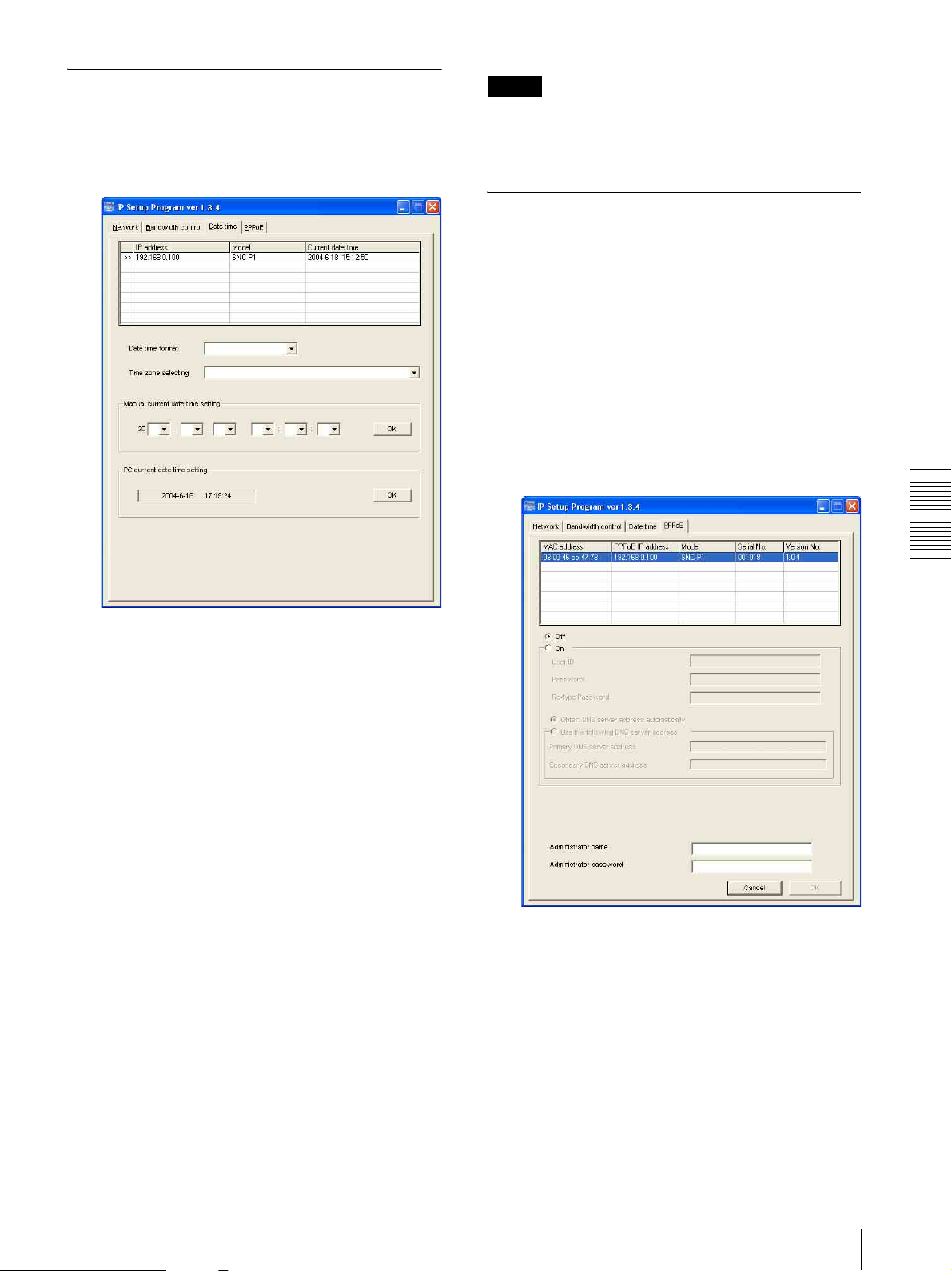
Date time Tab
Note
You can set the date and time on the camera.
1
Click the Date time tab to display the date/time
setting window.
Due to network properties, there may be a slight
difference between the displayed computer's date and
time and those set on the camera.
PPPoE Tab
PPPoE is used to connect to an ISP (Internet Service
Provider) via the Internet. Using PPPoE, you can
automatically obtain an IP address to connect to the
Internet from the ISP.
The following PPPoE setting items are provided for the
SNC-P1.
• User ID assigned by your ISP
• Password for the user ID
• DNS setting (automatic/manual setting)
1
Click the PPPoE tab to display the PPPoE setting
window.
Others
2
Click to select the camera you want to set the date
and time for.
You can select multiple cameras and set the date
and time simultaneously.
3
Select the date/time format from the Date time
format drop-down list.
4
Select the area where the camera is installed from
the Time zone selecting drop-down list.
5
Set the date and time.
You can set the date and time in two ways.
Manual current date time setting
Set the current date and time on the Manual
current date time setting boxes, and click OK.
The setting boxes are for the year (last two digits),
month, date, hour, minutes and seconds from left to
right.
PC current date time setting
The date and time set on the computer is displayed
in the PC current date time setting box.
Click OK on the right to set the camera’s date and
time to the displayed computer's date and time.
2
Click to select the camera you want to make the
PPPoE settings for.
3
Select On below the list to enable the PPPoE
setting.
To disable the PPPoE setting, select Off.
4
Type the user ID assigned by the ISP in the User ID
box.
5
Type the password for the user ID in the Password
box.
Using the Supplied Setup Program
55
Page 56
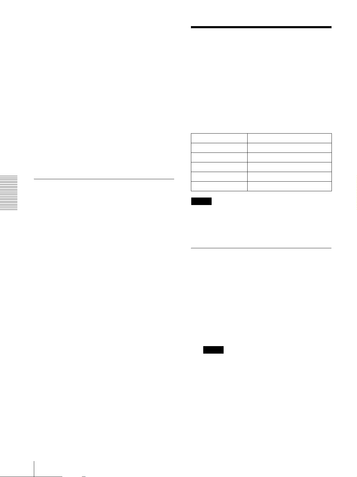
6
Retype the password for the user ID in the Re-type
password box.
7
Set the DNS server address.
Using the SNC audio
upload tool
— Transmitting
To obtain the DNS server addresses
automatically:
Select Obtain DNS server address automatically.
To specify the DNS server addresses manually:
Select Use the following DNS server address, and
type the Primary DNS server address and
Secondary DNS server address in each box.
8
Type the Administrator name and Administrator
password in each box.
9
Click OK.
If “Setting OK” is displayed, the PPPoE setting is
completed.
Rebooting the Camera
Click Reboot on the Network tab to reboot the camera.
It will take about two minutes to start again.
Others
Audio to Camera
The supplied SNC audio upload tool allows you to
transmit sound from the computer to the camera.
This section explains the setup and operations of the
SNC audio upload tool.
The SNC audio upload tool supports the following audio
data to be transmitted.
Audio CODEC Transmission rate
G711 (µ-LAW) 64 kbps
G.726 40 kbps
G.726 32 kbps
G.726 24 kbps
G.726 16 kbps
Note
Only one administrator can transmit sound to the
camera. Meanwhile, other user with administrator ID
and a password will not be able to transmit sound to the
camera.
Installing the SNC audio upload tool
1
Insert the supplied CD-ROM disc into your
computer CD-ROM drive.
After a short time a window will open displaying
the files on the CD-ROM.
2
Click the Setup icon of SNC audio upload tool.
The “File Download” dialog opens.
3
Click Open.
Note
If you click “Save this program to disk” on the “File
Download” dialog, you cannot install correctly.
Delete the downloaded file, and click Setup icon
again.
4
Install the SNC audio upload tool following the
wizard displayed.
If the Software License Agreement is displayed,
read it carefully and accept the agreement to
continue the installation.
56
Using the SNC audio upload tool — Transmitting Audio to Camera
Page 57
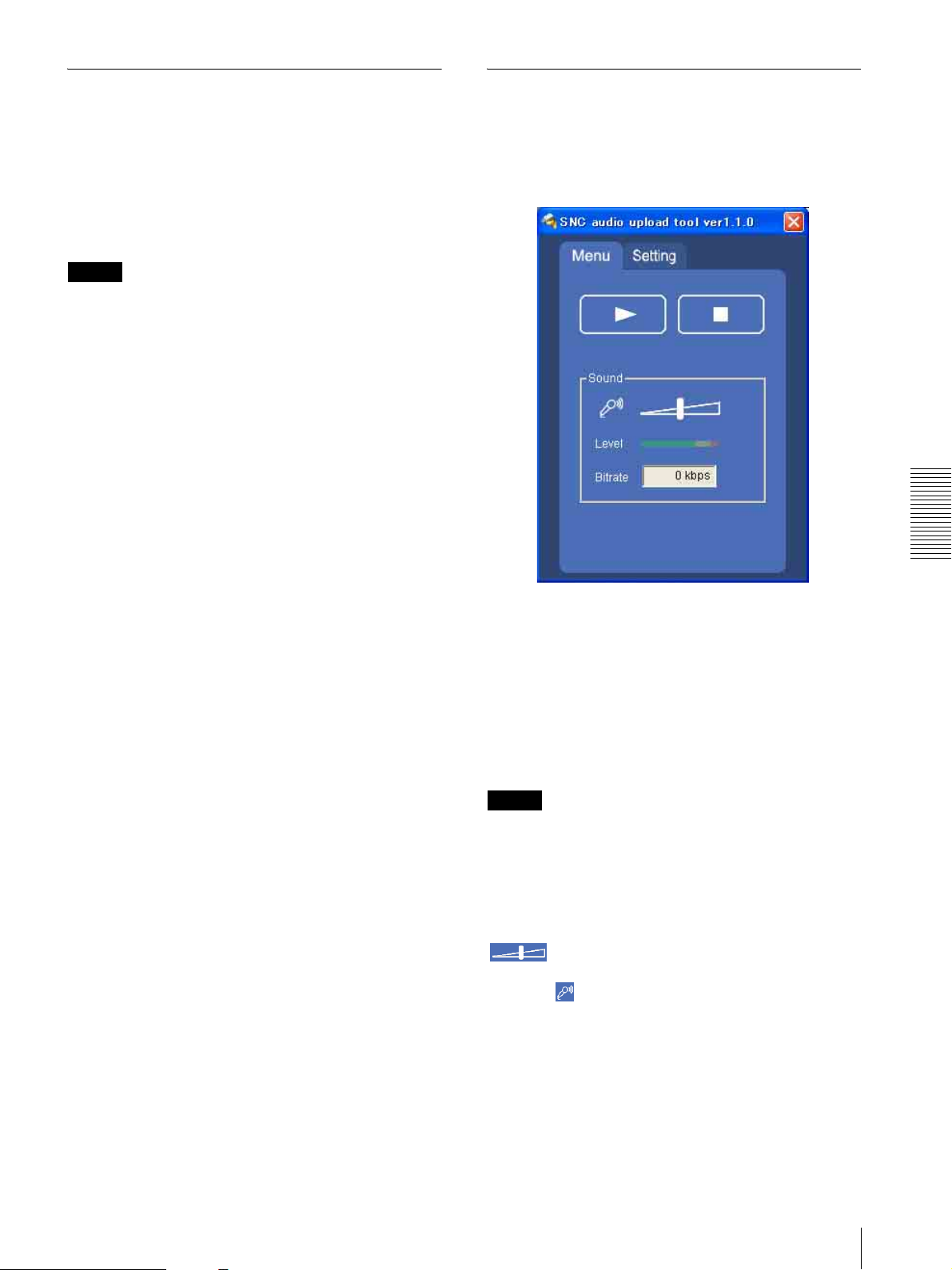
Connecting the Camera to the
Using the SNC audio upload tool
Computer
1
Connect a speaker to the 5 (line output) jack on the
camera.
2
Connect a microphone to the microphone input jack
on the computer.
Note
If the microphone input jack of the computer is not set
correctly, no sound is transmitted from the computer and
nothing is output from the speaker connected to the
camera.
Set the microphone input jack from the control panel of
Windows.
On Windows 2000
1 Select Sounds and Multimedia from Control Panel.
2 Click Vo l um e in the Sound Recording section on
the Audio tab.
The Recording Control window opens
3 Check Select in the Microphone section.
When you start the SNC Audio Upload Tool, the
following window is displayed.
Menu tab
Others
On Windows XP
1 Select Sounds and Audio Device from Control
Panel.
2 Click Vo l um e in the Sound Recording section on
the Audio tab.
The Recording Control window opens.
3 Check Select in the Microphone section.
N (start)/x(stop)
Click N (start) to start sound transmission. The
transmission speed is displayed in the Bitrate box during
transmission. You can adjust the microphone volume
and enable/disable the muting, if necessary.
To stop the sound transmission, click x(stop).
Note
If you change IP Address, Proxy Port, CODEC on the
Setting tab during the sound transmission, the changed
settings will be effective after the transmission.
Sound adjustment and indicators
Adjust the microphone input volume by moving the
slider bar. You can adjust the volume even
during the transmission.
Click the microphone icon to enable/disenable the
sound muting.
The transmission rate is displayed in the Bitrate box.
The microphone input volume is displayed at the Level.
Using the SNC audio upload tool — Transmitting Audio to Camera
57
Page 58
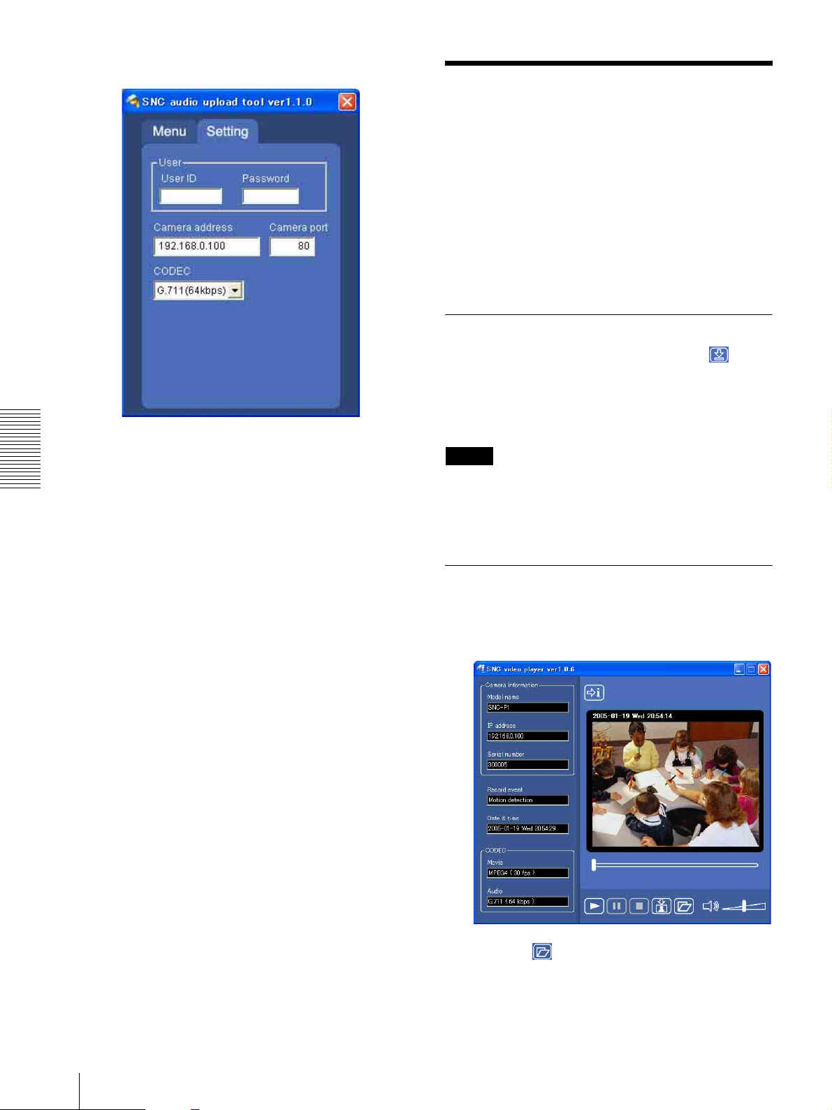
Setting tab
Using the SNC video player
— Playing Video/
Audio File Recorded on
Camera
The supplied SNC video player allows you to play
video/audio data recorded on the camera with your
computer.
This section explains the setup and operations of the
SNC video player.
Downloading the SNC video player
To download the SNC video player, click the Player
icon located on the upper part of the main viewer of the
camera.
Input the Administrator name and Administrator
password on the download dialog.
User
Set the User ID and Password for the administrator.
Others
The default setting of the User ID for the Administrator
is “admin,” and the Password is “admin.”
Camera address
Type the IP address or host name of the camera you want
to transmit sound.
Note
To operate the SNC video player, a special DLL file is
necessary. This file is automatically installed in the
computer when you view camera images with the
ActiveX viewer.
Using the SNC video player
Camera port
Set the port of the camera you want to transmit sound to.
The default port is “HTTP” (80).
CODEC
Select the audio mode (CODEC) from the drop-down
list.
1
Double-click the SNC video player downloaded
from the camera to start this application.
2
Click the icon.
The Select File dialog opens.
3
Select the file you want to play.
58
Using the SNC video player — Playing Video/Audio File Recorded on Camera
Page 59
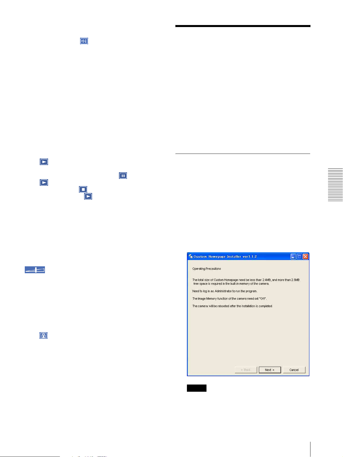
Information boxes on the selected file are displayed
on the left side of the window as follows:
Each click on the (information) icon switches
between “display” and “Not to display” of the file
information.
Model name: Model name of the camera with
which the file is recorded.
IP address: IP address of the camera with which
the file is recorded.
Serial number: Serial number of the camera with
which the file is recorded.
Record event: Type of event used for the
recording: Sensor input, Periodical, Motion
detection or Manual.
Date&time: Recording date and time
Movie: Video CODEC
Audio: Audio CODEC
Playing a video/audio file
Click (start) to start playing from the beginning of
the selected file.
To freeze the movie temporarily, click (pause).
Click again to restart playing.
To stop playing, click (stop).
To restart playing, click (start) again.
Play stops when the file is played to the end.
To play from a specified point
Move the slider bar below the image display, and the file
will play starts according to the position of the slider bar
position.
Using the Custom Homepage Installer
You can store the homepage that you have created in the
camera and watch it.
Notes on creating the homepage
When you are creating the homepage, note the following
points.
• The file name should be typed up to 24 characters
including the extension.
• The file size of the homepage should be 2.4 MB or
less.
• To see the created homepage, set the Default URL in
the System setting menu.
Uploading the Custom Homepage Installer to the Camera
1
After a short time a window will open displaying
the files on the CD-ROM.
2
Click the Setup icon of Custom Homepage
Installer.
The “File Download” dialog opens.
3
Click Open.
The installer starts and notes are displayed.
Others
Adjusting the sound
Adjust the playing sound volume by moving the
slider bar. Move it to the left end for the
minimum volume, and to the right end for the maximum
volume.
Click the speaker icon to enable/disable the sound
muting.
When the sound muting is on, no sound is heard even if
you move the slider bar to the right.
Saving an image
Click (capture) icon during playing or pause and the
captured image is displayed on a pop-up dialog. To save
the image, click Save on the dialog. You can specify the
destination to which the image is to be stored and select
the JPEG or Bitmap format.
Note
If you click “Save this program to disk” on the “File
Download” dialog, the
CustomHomepageInstaller.exe file will be saved on
the computer. Double-click the saved file to start it.
Using the Custom Homepage Installer
59
Page 60
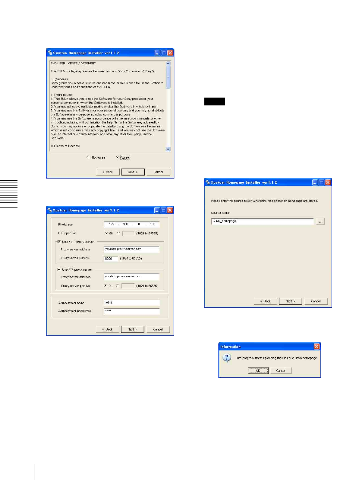
4
Read the notes carefully, and click Next>.
The Software License Agreement is displayed.
5
Read the agreement carefully, select Agree if you
accept it, then click Next.
When using an HTTP proxy server:
Select Use HTTP proxy server, and type your
settings in the Proxy server address and Proxy
server port No. boxes.
When using an FTP proxy server:
Select Use FTP proxy server, and type your
settings in the Proxy server address and Proxy
server port No. boxes.
Note
If you cannot establish communication with the
camera with the proxy server being used, connect
the camera to the local network and run the installer
without using the proxy server.
9
Type the Administrator name and Administrator
password of the camera to be uploaded.
10
Confirm that all items are correct, then click Next.
Others
11
Type the path for the folder in which your
homepage is stored in the Source folder box, then
click Next.
6
Type the IP address of the camera to be uploaded in
the IP address box.
7
Specify the HTTP port No. of the camera.
Initial HTTP port No is set to 80.
8
When you use a proxy server, set the following:
For the proxy server of your environments, consult
your network administrator.
60
Using the Custom Homepage Installer
12
Click OK.
Uploading of the homepage file starts.
Page 61
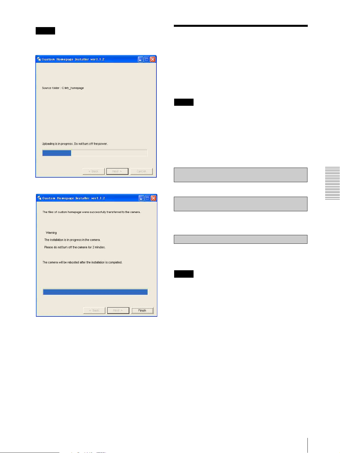
Note
Do not turn off the camera until the camera is
rebooted after uploading the homepage file.
The following page will appear after a while.
Assigning the IP Address to the Camera Using ARP Commands
This section explains how to assign an IP address to the
camera using ARP (Address Resolution Protocol)
commands without using the supplied setup program.
Note
When you turn on the camera, enter the ARP commands
within 5 minutes.
1
Open the DOS window on the computer.
2
Enter the IP address and the MAC address of the
camera to assign a new IP address to, using the
following ARP commands.
arp -s <Camera's IP address> <Camera's MAC address>
ping -t <Camera's IP address>
Example:
After displaying this page, the camera will be
adjusted and rebooted automatically in two
minutes.
13
Click Finish to exit the program.
arp -s 192.168.0.100 08-00-46-21-00-00
ping -t 192.168.0.100
3
When the following line is displayed on the DOS
window, hold down Ctrl and press C.
Reply from 192.168.0.100:bytes=32 time...
You will normally receive a reply after about 5
repetitions of "Request time out."
Note
If you do not receive a reply, check the following:
– Did you enter the ARP commands within 5 minutes
after it was turned on?
If not, turn off the camera and restart the operation.
– Is the NETWORK indicator on the camera flashing?
If the indicator goes off, the network connection has a
problem. Connect the network correctly.
– Did you enter the IP address previously used for
another device?
Assign a new IP address to the camera.
– Do the computer and the camera have the same
network address?
If not, set the same network address on the computer
and the camera.
Others
Assigning the IP Address to the Camera Using ARP Commands
61
Page 62
Using the SNMP
This unit supports SNMP (Simple Network
Management Protocol). You can read MIB-2 objects
and write some MIB-2 objects using software such as
SNMP manager software. This unit also supports the
coldStart trap which occurs when the power is turned on
or the unit restarts, and the Authentication failure trap
which informs of an illegal access using SNMP.
Using CGI commands, you can set community name
and access limitation, reading/writing right, host to send
traps, and some MIB-2 objects. To allow these settings,
you need authentication by the camera administrator.
4 describes the case of “mib-2.system. sysContact.0”.
This field is used to describe the information on
administrator of this camera. Nothing is set at the
factory.
5 describes the case of “mib-2.system. sysName.0”.
This field is used to describe administration mode
of this camera. Nothing is set at the factory.
6 describes the case of “mib-2.snmpEnable
AuthenTraps.0”. This example shows when “1”
(enable) is set. With this setting, a trap occurs when
there is an Authentication failure. When “2”
(disable) is set, no Authentication failure trap
occurs.
1. Inquiry Commands
You can check the SNMP Agent settings using the
following CGI commands.
<Method>
GET, POST
<Command>
“http://ip_adr/snmpdconf/inquiry.cgi?inqjs=snmp
(JavaScript parameter format)
Others
http://ip_adr/snmpdconf/inquiry.cgi?inq=snmp
(standard format)
With the above inquiry, you can obtain the following
setting information. The following explains the setting
information using the inqjs=snmp (JavaScript
parameter) format.
var sysDescr=“\“SONY Network Camera SNC-P1\””
...1
var sysObjectID=“1.3.6.1.4.1.122.8501” ...2
var sysLocation=“\“\”” ...3
var sysContact=“\“\”” ...4
var sysName=“\“\”” ...5
var snmpEnableAuthenTraps=“1” ...6
var community=“public,0.0.0.0,read,1” ...7
var community=“private,192.168.0.101,write,2” ...8
var trap=“public,192.168.0.101.1” ...9
1 describes the case of “mib-2.system. sysDescr.0”.
You cannot change this parameter.
7 describes the community name and the reading/
writing attributes. This example shows the
identification number “ID=1”, the community
name public, and enables read from any IP address
(0.0.0.0).
8 describes the community name and the reading/
writing attributes, similarly to 7. This example
shows the identification number ID=2, the
community name “private”, and enables “read/
write” by the SNMP request packet from the host
“192.168.0.101”.
9 describes the host name to send a trap. This
example shows the identification number “ID=1”,
the community name “public”, and enables sending
of traps to the host having the IP address
“192.168.0.101”.
2. Setting Commands
The unit supports the following setting commands of
SNMP.
<Method>
GET, POST
<Command>
http://ip_adr/snmpdconf/snmpdconf.cgi?
<parameter>=<value>&<parameter>=...&...
First, perform the settings of the following parameters.
2 describes the case of “mib-2.system.
sysObjectID.0”. You cannot change this parameter.
3 describes the case of “mib-2.system.
sysLocation.0”. This field is used to describe
information on the location of this camera. Nothing
is set at the factory.
62
Using the SNMP
1) sysLocation=<string>
Set the case of “mib-2.system.sysLocation.0” in the
<string> position. The maximum length of
<string> is 255 characters.
2) sysContact=<string>
Set the case of “mib-2.system.sysContact.0” in the
<string> position. The maximum length of
<string> is 255 characters.
Page 63
3) sysName=<string>
Set the case of “mib-2.system.sysName.0” in the
<string> position. The maximum length of
<string> is 255 characters.
4) enaAuthTraps=<value>
Set the case value of “mib-2.snmp.snmp
EnableAuthenTraps.0” in the <string> position.
Type “1” (enable) or “2” (disable) in the <value>
position.
5) community=<ID>,<rwAttr>,
<communityName>,<IpAddressString>
Set the community name and the reading/writing
attributes. <ID> describes the setting identification
number (1 to 8), <rwAttr> describes a character
representing the reading/writing attribute (“r”, “R”,
“w or “W”), <communityName> describes the
community name to be set, and <IpAddressString>
describes the IP address of the host you allow
access (0.0.0.0 for any host).
Example: To allow reading/writing by any host in the
“private” community and having the ID number “2”.
community=2,w,private,0.0.0.0
<Command>
http://ip_adr/snmpdconf/snmpdconf.cgi?
snmpd=restart
6) trap=<ID>,<communityName>,
<IpAddressString>
Set the host you want to send traps to. <ID>
describes the setting identification number (1 to 8),
<communityName> describes the community
name to send traps to, and <IpAddressString>
describes the IP address of the host to send traps to.
Example: To specify the destination of traps as the
private community and the ID number “1”.
rap=1,public,192.168.0.101
7) delcommunity=<ID>
This parameter is used to delete the previous
community setting. <ID> describes the community
setting identification number (1 to 8).
8) deltrap=<ID>
This parameter is used to delete the previous setting
of the host to send traps to. <ID> describes the trap
setting identification number (1 to 8).
When you have finished changing the SNMP setting
information using the above parameters 1) to 8), check
the changed settings using an inquiry commands. If the
changed settings are OK, restart the SNMP using the
following CGI command.
Others
SNMP restart command
<Method>
GET, POST
Using the SNMP
63
Page 64

Custom Homepage Installer...........27
Index
D
Date & time ....................................27
A
Access log ......................................29
access right .....................................38
ActiveX viewer...............................15
activity detection function.............. 52
Administrator ...........................13
administrator ............................ 13
Administrator e-mail address ......... 24
administrator menu page................26
Advanced mode..............................25
Advanced mode Menu ...................25
Alarm..............................................43
alarm................................... 42
Alarm buffer....................... 26
alarm buffer........................ 26
Alarm buffer setting Menu.............51
Alarm output ...................... 20
Others
alarm output ....................... 20
Alarm output setting Menu ............48
Alarm recording .............................45
Alarm sending ..........................40
ARP commands..............................61
Authentication ................................23
authentication .................................23
, 37
, 37
, 43, 48
, 43, 51
, 43, 51
, 26, 48
, 26, 48
, 42
B
Backup setting data ........................ 28
Bandwidth ......................................54
Blue LED ................................. 23
blue LED .................................. 23
Brightness.......................................23
brightness .......................................23
, 27
, 27
Date & time setting ........................23
date and time ...................... 23
default gateway...............................34
Default policy................................. 38
DHCP .............................................33
Digital zoom.............................16
digital zoom.............................. 16
DNS server .....................................34
Dynamic IP address notification ....35
, 27, 55
, 18
, 18
E
Easy mode ......................................22
e-Mail .............................................26
e-Mail (SMTP) .........................23
e-Mail (SMTP) setting Menu .........39
e-Mail address ................................36
, 26
F
Factory default................................28
factory settings ...............................28
flash memory..................................27
Flickerless.......................................31
For the customers in the U.S.A. .......2
format of date and time ..................27
Frame rate.................................16
frame rate..................................16
free space........................................45
FTP client .................................26
FTP client setting Menu .................42
FTP server ................................26
FTP server setting Menu ................48
, 17
, 17
, 50
, 42
image size.................................16
Internet Explorer.............................11
IP Address ........................................9
IP address ............................. 9
IP address notification....................35
, 30
, 14, 33
J
Java applet viewer ..........................15
JPEG......................................... 29
, 32
L
loading the setting data...................28
logging in........................................14
M
MAC address..................................33
main viewer ..............................11, 16
main viewer page............................16
memory...........................................44
menu section...................................16
Message..........................................24
Microphone ....................................23
Mode............................................... 24
monitor Image ................................17
monitor image section ....................17
Motion detection.......................26
motion detection.......................26
Motion detection setting Menu.......52
Mount .............................................22
MPEG4..................................... 29
, 52
, 52
, 32
N
Network.................................... 26, 33
network.....................................26
network configuration ....................33
Network setting Menu....................33
, 33
H
C
Camera ...........................................26
camera setting.................................29
Camera setting Menu ..................... 29
Cancel button.................................. 25
Capture .....................................16
capture ...................................... 16
CGI commands...............................62
communication bandwidth.............54
contrast ...........................................32
Cropping.........................................30
cropping..........................................30
, 18
, 18
Home ..............................................16
Homepage Custom Tool .................59
HTTP..............................................36
HTTP port number .........................10
I
Image memory..........................20, 26
image memory..........................20
Image memory setting Menu..........44
Image quality..................................23
image quality ..................................23
Image size.................................23
, 26
, 30
O
OK button .......................................25
overwrite.........................................45
P
Password...................................24, 37
password...................................24
Periodical recording .......................46
periodical recording........................46
Periodical sending ....................41
periodical sending.....................41
Picture.............................................31
, 37
, 43
, 43
64
Index
Page 65

Player ............................................. 16
POP server name............................ 23
port number.................................... 34
PPPoE ............................................ 55
proxy server ................................... 36
R
Reboot...................................... 28, 56
reboot ..................................28
Recipient e-mail address................ 24
recording images............................ 44
reset................................................ 33
, 29, 56
T
TCP ................................................ 21
TCP/UDP ................................. 16
time difference ............................... 28
Time zone....................................... 28
time zone........................................ 28
title ................................................. 36
title bar ........................................... 27
Title bar name ................................27
Trigger...........................16
trigger............................16
Trigger setting Menu......................49
, 21
, 19, 26, 49
, 19, 26, 49
S
saturation........................................ 31
saves the setting data...................... 28
Schedule................................... 26
schedule ................................... 26, 51
Schedule setting Menu................... 51
Security .......................................... 26
security........................................... 26
security setting ............................... 38
Security setting Menu .................... 38
sending images............................... 42
Serial number................................. 27
serial number.................................. 27
Setting ...................................... 16
Setup Program............................ 9
sharpness........................................ 32
SMTP server .................................. 35
SMTP server name......................... 23
SNC audio upload tool................... 56
SNC video player........................... 58
SNMP............................................. 62
Software version ............................ 27
software version............................. 27
special tags..................................... 36
Subject ........................................... 24
subject ............................................ 24
subnet mask.................................... 34
System...................................... 26
system configuring......................... 27
System log...................................... 29
, 51
, 22
, 54
, 27
U
UDP (Multicast)............................. 21
UDP (Unicast)................................ 21
URL................................................ 27
User .....................................13
user......................................13
User name ................................ 24
user name ................................. 24
user setting ..................................... 37
User setting Menu ..........................37
, 26, 37
, 26, 37
, 37
, 37
V
View size .................................. 16, 18
view size................................... 16
viewer.............................................15
Viewer mode .................................. 37
viewer mode................................... 37
volume............................................ 17
, 18
W
welcome page......................11, 14, 27
White balance.................................22
white balance ................................. 22
Sony Corporation
 Loading...