

Page 1

Network Camera
3-991-873-11 (1)
User’s Guide
Software Version 1.1
SNC-DP10
© 2006 Sony Corporation
Page 2

Owner’s Record
For customers in the U.S.A.
The model and serial numbers are located on the bottom.
Record the serial number in the space provided below.
Refer to these numbers whenever you call upon your
Sony dealer regarding this product.
Model No. SNC-DP10
Serial No.
WARNING
To avoid electrical shock, do not open the
cabinet. Refer servicing to qualified
personnel only.
WARNING
This installation should be made by a qualified service
person and should conform to all local codes.
WARNING
A readily accessible disconnect device shall be
incorporated in the building installation wiring.
WARNING (For Installers only)
Instructions for installing the equipment on the ceiling:
After the installation, ensure the connection is capable
of supporting four times the weight of the equipment
downwards.
This device complies with Part 15 of the FCC Rules.
Operation is subject to the following two conditions:
(1) This device may not cause harmful interference,
and (2) this device must accept any interference
received, including interference that may cause
undesired operation.
NOTE: This equipment has been tested and found to
comply with the limits for a Class A digital device,
pursuant to part 15 of the FCC Rules. These limits are
designed to provide reasonable protection against
harmful interference when the equipment is operated in
a commercial environment. This equipment generates,
uses, and can radiate radio frequency energy and, if not
installed and used in accordance with the instruction
manual, may cause harmful interference to radio
communications. Operation of this equipment in a
residential area is likely to cause harmful interference in
which case the user will be required to correct the
interference at his own expense.
You are cautioned that any changes or modifications not
expressly approved in this manual could void your
authority to operate this equipment.
All interface cables used to connect peripherals must be
shielded in order to comply with the limits for a digital
device pursuant to Subpart B or Part 15 of FCC Rules.
CAUTION
The rating label is located on the bottom.
CAUTION for LAN port
For safety reason, do not connect the LAN port to any
network devices that might have excessive voltage.
POWER REQUIREMENTS
The SNC-DP10 operates on 24 V DC or 12 V DC.
The SNC-DP10 automatically detects the power.
CAUTION for U.S.A. and Canada
Use a Class 2 power suply which is UL Listed (in the
U.S.A.) or CSA-certified (in Canada).
CAUTION for other countries
Use a power supply rated 24 V DC or 12 V DC which
meets the requirements for SELV (Safety Extra Low
Voltage) and complies with Limited Power Source
according to IEC 60950.
For customers in Canada
This Class A digital apparatus complies with Canadian
ICES-003.
Cet appareil numérique de la classe A est conforme à la
norme NMB-003 du Canada.
For customers in other countries
WARNING
This is a Class A product. In a domestic environment,
this product may cause radio interference in which case
the user may be required to take adequate measures.
In the case that interference should occur, consult your
nearest authorized Sony service facility.
ATTENTION
The electromagnetic fields at specific frequencies may
influence the picture of the unit.
WARNING (for service personnel only)
There is danger of explosion if batteries are mishandled.
Dispose of batteries properly in accordance with the
manufacturer’s instructions and all applicable local
regulations.
2
Page 3

NOTICE TO USERS
© 2006 Sony Corporation. All rights reserved. This
manual or the software described herein, in whole or in
part, may not be reproduced, translated or reduced to
any machine readable form without prior written
approval from Sony Corporation.
SONY CORPORATION PROVIDES NO
WARRANTY WITH REGARD TO THIS MANUAL,
THE SOFTWARE OR OTHER INFORMATION
CONTAINED HEREIN AND HEREBY EXPRESSLY
DISCLAIMS ANY IMPLIED WARRANTIES OF
MERCHANTABILITY OR FITNESS FOR ANY
PARTICULAR PURPOSE WITH REGARD TO THIS
MANUAL, THE SOFTWARE OR SUCH OTHER
INFORMATION. IN NO EVENT SHALL SONY
CORPORATION BE LIABLE FOR ANY
INCIDENTAL, CONSEQUENTIAL OR SPECIAL
DAMAGES, WHETHER BASED ON TORT,
CONTRACT, OR OTHERWISE, ARISING OUT OF
OR IN CONNECTION WITH THIS MANUAL, THE
SOFTWARE OR OTHER INFORMATION
CONTAINED HEREIN OR THE USE THEREOF.
Sony Corporation reserves the right to make any
modification to this manual or the information contained
herein at any time without notice.
The software described herein may also be governed by
the terms of a separate user license agreement.
• Microsoft, Windows, Internet Explorer and MS-DOS
are registered trademarks of Microsoft Corporation in
the United States and/or other countries.
• Intel and Pentium are registered trademarks of Intel
Corporation or its subsidiaries in the United States and
other countries.
• Adobe, Acrobat and Adobe Reader are trademarks of
Adobe Systems Incorporated in the United States and/
or other countries.
All other company and product names are trademarks or
registered trademarks of the respective companies or
their respective makers.
3
Page 4

Table of Contents
Overview
Features ....................................................................................... 6
How to Use This User’s Guide ................................................... 6
Precautions .................................................................................. 7
Operating the Camera
Logging in to Homepage — Welcome Page ............................. 8
Configuration of Main Viewer ................................................... 10
Capturing a Monitor Image ....................................................... 11
Operating Precautions ........................................................................ 7
Logging in as a User ..........................................................................8
Logging in as Administrator .............................................................. 8
About Viewers ...................................................................................9
Administrating the Camera
Configuration of Administrator Menu Page ............................ 12
Configuring the System — System setting Page.................... 13
System setting Section ..................................................................... 13
Date time setting Section .................................................................14
Initialization Section ........................................................................ 15
Setting the Camera — Camera setting Page........................... 16
Camera setting Section..................................................................... 16
Temperature setting section .............................................................18
Camera control mode setting section ...............................................19
Configuring the Network — Network setting Page................. 20
Wired LAN setting Section..............................................................20
HTTP port setting Section................................................................20
Setting the User — User setting Page ..................................... 21
Setting the Security — Security setting Page......................... 22
Activating/Deactivating the Security Function
Setting the Security Function —Securing setting Page ................... 22
— Security usage setting Page ...............................................22
4
Table of Contents
Page 5

Others
Sending Images to FTP Server — FTP client setting Page .... 23
Activating/Deactivating the FTP Client Function
— FTP client usage setting Page............................................ 23
Setting the FTP Client Function — FTP client setting Page........... 23
Downloading Stored Images— FTP server setting Page ....... 24
Activating/Deactivating the FTP Server Function
— FTP server usage setting Page........................................... 24
Setting the FTP Server Function — FTP server setting Page.......... 24
Sending an Image via E-mail — SMTP setting Page............... 25
Activating/Deactivating the SMTP Function
— SMTP usage setting Page .................................................. 25
Setting the SMTP Function — SMTP setting Page......................... 25
Using the Supplied Setup Program ......................................... 26
Assigning an IP address using the Setup Program .......................... 26
Changing the Communication Bandwidth....................................... 28
Setting the Date and Time ............................................................... 28
Rebooting the SNC-DP10................................................................ 29
Assigning the IP Address to the Camera Using ARP Com-
mands...................................................................................29
Using the SNMP ......................................................................... 30
1. Inquiry Commands ..................................................................... 30
2. Setting Commands...................................................................... 30
Specifications.............................................................................32
Index............................................................................................ 34
Table of Contents
5
Page 6
Overview
How to Use This User’s Guide
Overview
Features
This is dome-shaped color video camera for which the 1/
2.7 type CCD is adopted. It has the following features.
Camera section
• The Panoramic Annular Lens (PAL) allows shooting
of a ring-shaped 360° panoramic image. You can view
the shot image in ring mode or dual half wide mode in
that the 360° annular image is separated by 180° and
displayed as two panorama images.
• The best picture quality is available in the lowest light
degree (0.3 lux) to the object (in the color mode).
• High quality CCD and the clear dome cover enable to
get high sensitivity.
1)
•IP66
1)IP66 is a protection grade provided under JIS and IEC.
Network section, Control section
• Real-time monitoring of the image from the camera is
• M-JPEG video compression allows smooth streaming
Others
• The camera is supplied with the IP Setup Program for
sealed enclosure (sturdy and weatherproof
structure) suitable for outdoor installation
possible using the Web browser on the computer.
of motion pictures with 30 fps (VGA size).
easy performance of the network setting.
This User’s Guide explains how to operate the SNCDP10 Network Camera from a computer.
The User’s Guide is written to be read on the computer
display.
As this section gives tips on using the User’s Guide, read
it before you operate this unit.
Jumping to the related page
When you read the User’s Guide on the computer
display, click on the sentence to jump to the related page.
Software display examples
Note that the displays shown in the User’s Guide are
explanatory examples. Some displays may be different
from the ones which appear as you operate the
application software.
Printing the User’s Guide
Depending on your system, certain displays or
illustrations in the User’s Guide, when printed out, may
differ from those as portrayed on your screen.
Installation Manual (printed matter)
The supplied Installation Manual describes the names
and functions of parts and controls of the Video Network
Station, connecting examples and how to set up this unit.
Be sure to read the Installation Manual before operating.
• You should keep in mind that the images or audio you are
monitoring may be protected by privacy and other legal
rights, and the responsibility for making sure you are
complying with applicable laws is yours alone.
• Access to the images and audio is protected only by a user
name and the password you set up. No further
authentication is provided nor should you presume that
any other protective filtering is done by the service. Since
the service is Internet-based, there is a risk that the image
or audio you are monitoring can be viewed or used by a
third-party via the network.
6
Features / How to Use This User’s Guide
Page 7
Precautions
This Sony product has been designed with safety in
mind. However, if not used properly electrical products
can cause fires which may lead to serious body injury.
To avoid such accidents, be sure to heed the following.
Heed the safety precautions
Be sure to follow the general safety precautions and the
“Operating Precautions.”
In case of a breakdown
In case of system breakdown, discontinue use and
contact your authorized Sony dealer.
In case of abnormal operation
• If the unit emits smoke or an unusual smell,
• If water or other foreign objects enter the cabinet, or
• If you drop the unit or damage the cabinet:
1
Disconnect the power cable and the connecting
cables.
2
Contact your authorized Sony dealer or the store
where you purchased the product.
Cleaning
• Use a soft, dry cloth to remove the fingerprints or dust
from the lens and clear dome cover.
• Use a blower to remove dust from the lens.
• Clean the body with a dry soft cloth. If it is very dirty,
use a cloth dampened with a small quantity of neutral
detergent, then wipe dry.
• Do not use volatile solvents such as alcohol, benzene
or thinners as they may damage the surface finishes.
In the event of any problems with the operation of the
camera, contact your Sony dealer.
Note on laser beams
Laser beams may damage the CCDs. If you shoot a scene that
includes a laser beam, be careful not to let a laser beam
become directed into the lens of the camera.
Overview
Operating Precautions
Operating or storage location
• Avoid shooting very bright objects (such as light
fittings or sunlight) for an extended period.
• Take adequate waterproofing measure when installing
the unit in a place where it gets wet.
• Avoid operating or storing the unit in the following
locations:
– Extremely hot or cold places (operating
temperature: -20 °C to +50 °C [-4 °F to +122 °F] for
continuous operation, or -5 °C to +50 °C [23 °F to
122 °F] for starting the unit
– Close to excessively dusty places
– Where exposed to mechanical vibrations
– Close to sources of powerful electromagnetic
radiation, such as radios or TV transmitters
– Close to fluorescent lamps or objects reflecting light
– Under unstable light sources (it may cause
flickering)
– Close to sources of strong magnetism
1)Turn on the power of the unit within the operating
temperature range for starting the unit (-5
°F to 122 °F]).
[23
1)
)
°C to +50 °C
Attaching the dome casing
Attach the dome casing securely with the supplied
wrench.
Precautions
7
Page 8
1
Select Tool from the menu bar of Internet Explorer,
Operating the Camera
The Operating the Camera section explains how to
monitor the image from the camera using your Web
browser. Use Internet Explorer as the Web browser.
The functions of the camera should be set by the
Administrator. For the setting of the camera, see
“Administrating the Camera” on page 12.
Operating the Camera
then select Internet Options and Security tab in
sequence.
2
Click the Internet icon (when using this unit via
the Internet) or Local intranet icon (when using
this unit via a local network).
3
Set the slider to Medium or lower. (If the slider is
not displayed, click Default Level.)
When using antivirus software in the
Logging in to Homepage
— Welcome Page
Logging in as a User
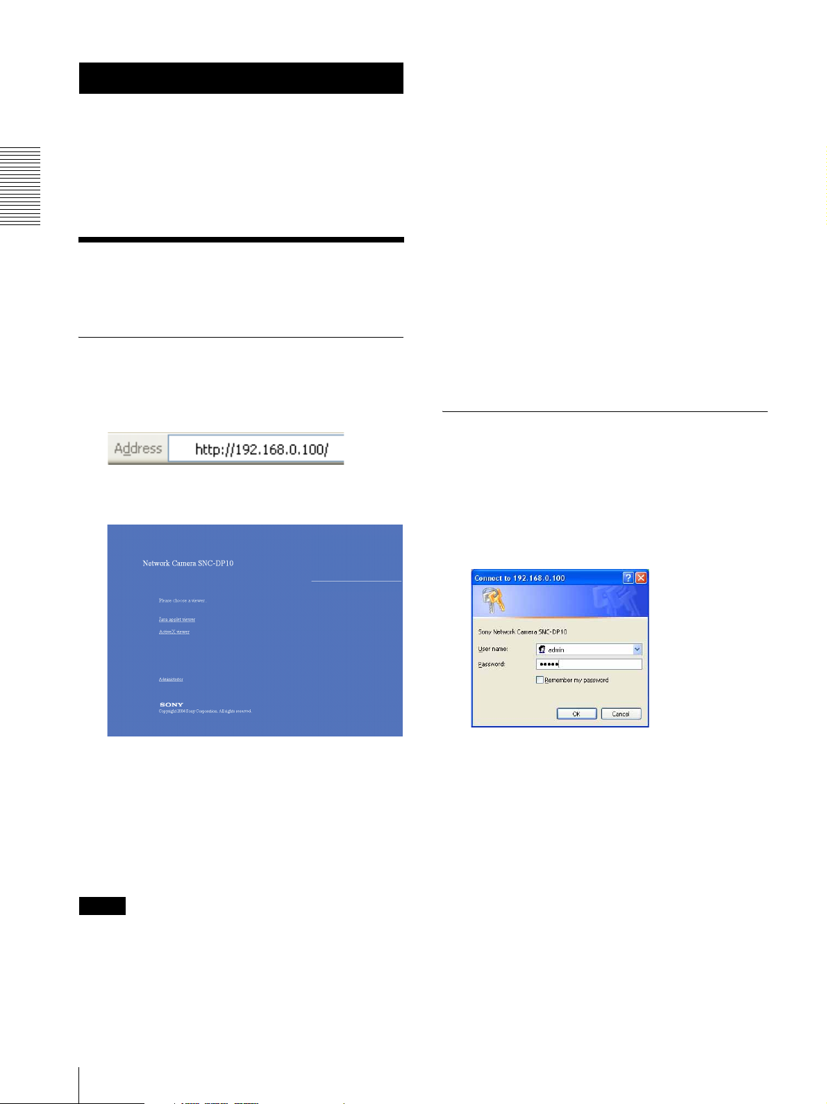
1
Start the web browser on your computer and type
the IP address of the camera you want to monitor.
computer
• When you use antivirus software in your computer, the
performance of this unit may be reduced, for example,
the frame rate for displaying the image may lower.
• The Web page displayed when you log in this unit uses
Java Script. The display of the page may be affected
if you use antivirus software in your computer.
Logging in as Administrator
If you log in this unit as the Administrator, you can
perform all the settings provided with the software. The
The welcome page of Network Camera is
displayed.
Administrator may be logged in at any time, regardless
of the number of the users being accessed.
2
Click to select the viewer.
You can select the viewer Java applet viewer or
ActiveX viewer, whichever is suitable for your
system environments and usage.
For details, see “About Viewers” on page 9.
When you have selected the viewer, the main
viewer appears (see page 10).
Note
To operate the welcome page correctly, set the security
level of the Internet Explorer to Medium or lower, as
follows:
1
Click Administrator on the welcome page.
The login page appears.
8
Logging in to Homepage — Welcome Page
Page 9

2
Enter the user name and password for
Administrator, then click OK.
The user name “admin” and the password “admin”
are set at the factory for the Administrator. You can
change them on the User setting page in the
Administrator menu (see page 12).
The welcome page is changed to that for
Administrator.
3
Select the viewer.
You can select the viewer Java applet viewer or
ActiveX viewer, whichever is suitable for your
system environments and usage.
For details, see “About Viewers” on page 9.
When you have selected the viewer, the main
viewer appears (see page 10).
Other functions on the welcome page for
Administrator
Setting
Click to display the Administrator menu (see page 12).
Home
Click to return to the normal welcome page.
About Viewers
You can select one of the following viewers.
Java applet viewer
It displays the main viewer using Java.
The frame rate is lower than the ActiveX viewer.
The Java applet viewer operates only when Java is
installed and Java (Sun) is enabled. If it does not operate
correctly, check whether the specified Java version has
been installed successfully and Java (Sun) is enabled.
Java (Sun) is not displayed, it means that Java is not
installed. You need to install Java.
Java Plug-in Ver. 1.5.0_04, Ver. 1.5.0_05
To enable Java Plug-in
Check “Use Java 2 v1.5.0_xx for <applet> (requires
restart)” in “Java (Sun)”.
To install Java Plug-in
Download Java 2 Runtime Environment, Standard
Edition (JRE) from the website of Sun Microsystems,
Inc., and install it by following the instructions on the
installer.
ActiveX viewer
It displays the main viewer using ActiveX.
With this viewer, you can display images at a high frame
rate.
When you log in this unit using Internet Explorer for the
first time, the Security Warning appears. Click Ye s and
install ActiveX Control.
Notes
• If the Java applet viewer is selected, the image may be
turned around in the display when the viewer is started
up with Mount of Camera setting section (page 18)
set to Desktop. This image is not corrected if you set
Mount mode to Ceiling.
When you use the camera with Desktop installation,
we recommend u
• If Automatic configuration is enabled in the Local
Area Network (LAN) Settings of Internet Explorer,
the camera image may not be displayed. In that case,
disable Automatic configuration and set the Proxy
server manually. For the setting of the Proxy server,
consult your network administrator.
• When you install ActiveX viewer on Windows 2000
or Windows XP, you should be logged in to the
computer as the Administrator.
• The phrase"SNT-V501 Image Viewer"appears in the
text of the "Security warning." This is because this
unit uses the same viewer as that of the model SNTV501, and does not cause any problem in practical
use.
Tip
Every page of this software is optimized for display
character size Medium for Internet Explorer.
Operating the Camera
To check the Java version
Select Tools from the menu bar of Internet Explorer,
then select Internet Options and click the Advanced
mode tab. Check whether the version of Java displayed
for Java (Sun) is one of the versions specified below. If
Logging in to Homepage — Welcome Page
9
Page 10
Configuration of Main Viewer
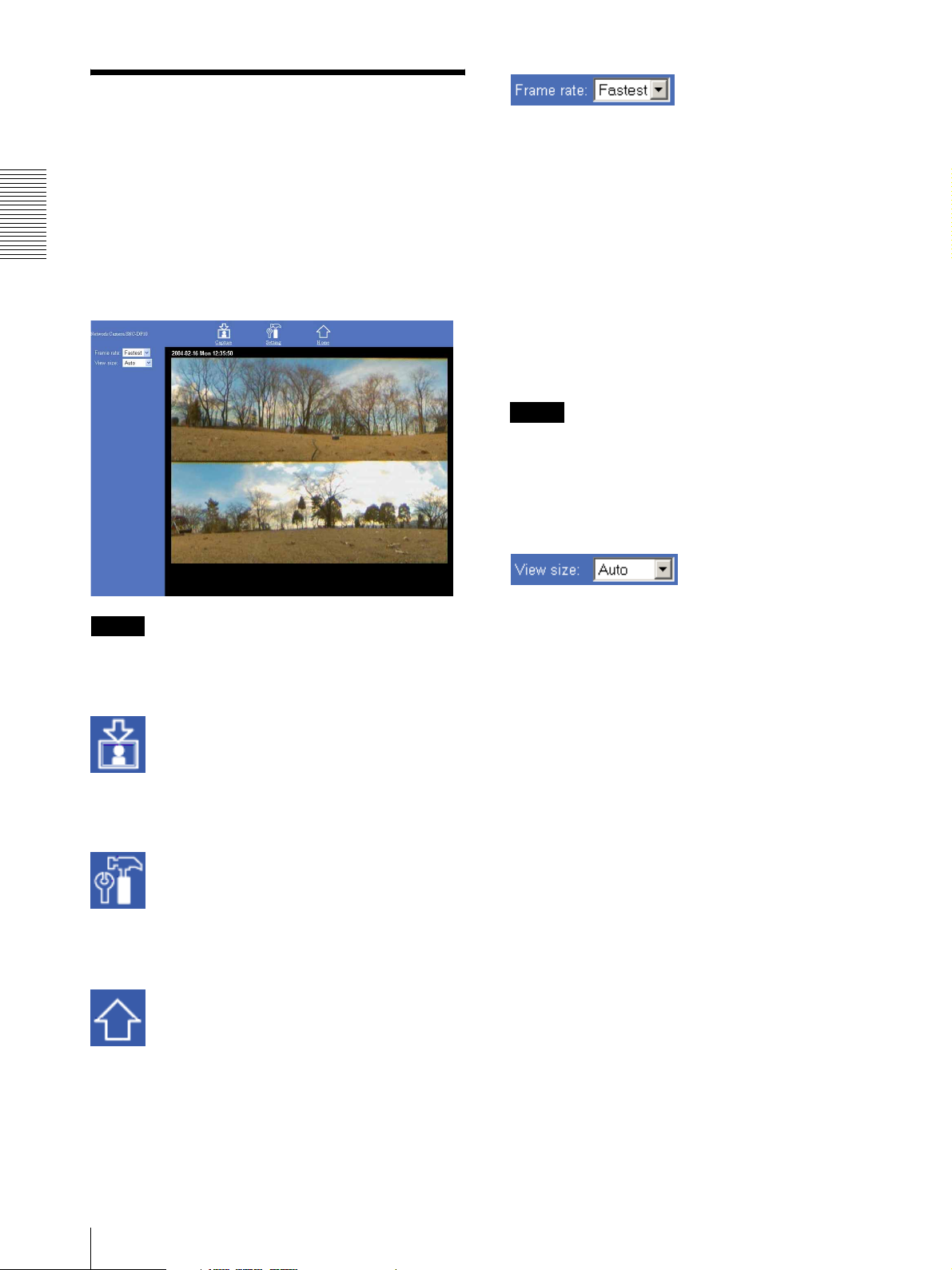
When you select the viewer, the main viewer is
displayed.
This section briefly explains the functions of the parts
and controls on the main viewer. For a detailed
explanation on each part or control, see the specified
Operating the Camera
pages.
Main viewer
Click the down-arrow button in the Frame rate box and
select the frame rate with which the images are
transmitted, from the drop-down list.
You can select the frame rate from among the following:
For the NTSC camera:
1, 2, 3, 4, 5, 6, 8, 10, 15, 20, 25, Fastest
For the PAL camera:
1, 2, 3, 4, 5, 6, 8, 12, 16, 20, Fastest
The numbers indicate “FPS” (the number of frames
transmitted per second).
With Fastest, the camera transmits the maximum
number of frames possible for the connected line. The
maximum frame rate is 30 FPS (NTSC) or 25 FPS
(PAL).
Note
The frame rate options indicate the maximum number of
frames that can be transmitted. The number of frames
actually transmitted may vary depending on the network
environments and camera settings (image size and
image quality settings).
Frame rate
Tip
The available functions are limited by user access right.
You can change user access right on the User setting
page (see page 21).
Capture
Captures a still image shot by the camera and stores it in
the computer. (See “Capturing a Monitor Image” on
page 11.)
Setting
Displays the Administrator menu. (See “Configuration
of Administrator Menu Page” on page 12.)
User access right Level 4 is required for this function.
Home
Displays the Welcome page.
View size
Click the down-arrow button in the View size box and
select the view size from the drop-down list.
You can select the view size from among the following:
Auto, 640 × 480, 320 × 240, 160 × 120
Auto is determined by the image size specified with
Image size on the Camera setting page (see page 16).
10
Configuration of Main Viewer
Page 11
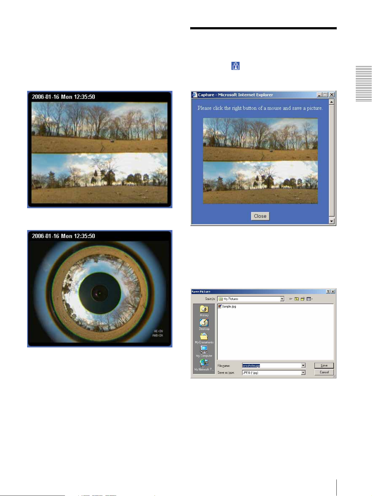
Monitor image
The image shot by the camera is shown here. Regarding
the camera image, DualHalfWide mode or Ring mode
can be selected in Camera mode (page 17) of Camera
setting.
The date and time is displayed at the top of the window.
DualHalfWide
Capturing a Monitor Image
If you click the Capture button on the main viewer,
the current still image is captured and displayed on the
monitor image section.
Operating the Camera
Ring
To save the captured image
Right-click on the monitor image and select Save As
from the menu. Then, the Save Picture dialog appears.
Type the file name and specify the destination to which
the image file is to be stored, and click Save. The image
is saved in the JPEG format.
Capturing a Monitor Image
11
Page 12
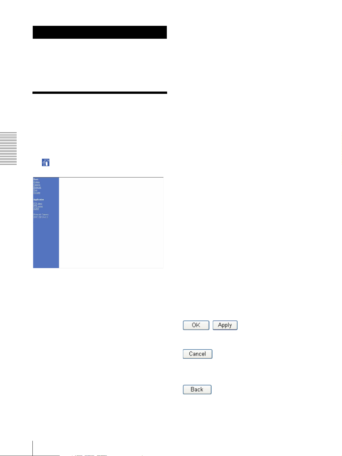
Administrating the Camera
The Administrating the Camera section explains how to
set the functions of the camera by the Administrator.
For the monitoring of the camera image, see “Operating
the Camera” on page 8.
Camera
Displays the Camera setting page.
See “Setting the Camera — Camera setting Page” on
page 16.
Network
Displays the Network setting page.
See “Configuring the Network — Network setting
Page” on page 20.
Configuration of
User
Displays the User setting page.
See “Setting the User — User setting Page” on page 21.
Administrator Menu
Page
The Administrator menu page is displayed when the
Administrator having Level 4 access right selects
Setting on the welcome page for Administrator, or when
Administrating the Camera
the Setting button on the menu section of the main
viewer is clicked.
Security
Displays the Security setting page.
See “Setting the Security — Security setting Page” on
page 22.
Application menu
FTP client
Displays the FTP client setting page.
See “Sending Images to FTP Server — FTP client
setting Page” on page 23.
FTP server
Displays the FTP server setting page.
See “Downloading Stored Images — FTP server setting
Page” on page 24.
SMTP
Displays the SMTP setting page.
See “Sending an Image via E-mail — SMTP setting
Page” on page 25.
The Administrator menu consists of the Basic menu and
the Application menu. The Basic menu is used for basic
settings of this unit, and the Application menu is used
for setting various applications according to individual.
Click on each menu name to display its setting page.
Basic menu
System
Displays the System setting page.
See “Configuring the System — System setting Page”
on page 13.
12
Configuration of Administrator Menu Page
Buttons common to every setting page
The following buttons are displayed on the setting pages
where they are necessary. The functions of the buttons
are the same on every setting page.
Click this button to validate the settings.
Click this button to invalidate the set values and return to
the previous settings.
Click this button to return to the top of the setting page.
Page 13
General notes on setting pages
• After changing a setting on a setting page, wait at least
10 seconds before turning off the power this unit.
If the power is turned off immediately, the changed
setting may not be stored correctly.
• When you display the Area setting page, the size of the
image on the main viewer may change for a while.
This is not a problem.
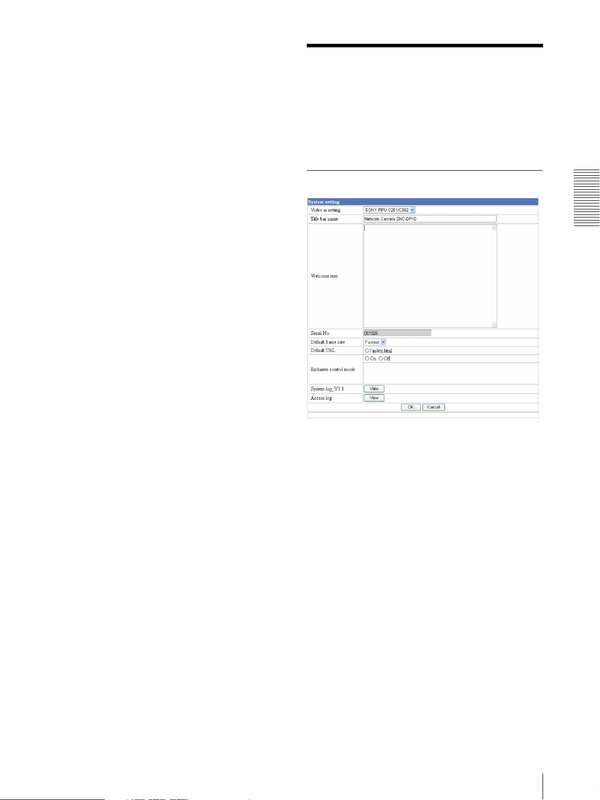
Configuring the System
— System setting Page
When you click System on the Administrator menu, the
System setting page appears.
Use this page to perform the principal settings of the
software.
System setting Section
Administrating the Camera
Video in setting
Only SONY RPU-C251/352 can be selected in this
camera.
Title bar name
Type a name to display on the title bar up to 32
characters.
Welcome text
Type a text to show on the welcome page, in HTML
format, up to 1,024 characters. Use the <BR> tag for a
line break. (A line break is equivalent to 2 characters.)
Serial No.
Displays the serial number of this unit.
Configuring the System — System setting Page
13
Page 14
Default frame rate
Select the initial frame rate which is selected when you
log in this unit and display the main viewer.
Click the down-arrow button in the box and select the
frame rate from the drop-down list.
The selectable frame rates are the following:
For the NTSC camera:
1, 2, 3, 4, 5, 6, 8, 10, 15, 20, 25, Fastest
For the PAL camera:
1, 2, 3, 4, 5, 6, 8, 12, 16, 20, Fastest
The numbers indicate “FPS” (the number of frames
transmitted per second).
With Fastest, the camera transmits the maximum
number of frames possible for the connected line. The
maximum frame rate is 30 FPS (NTSC) or 25 FPS
(PAL).
Notes
• Before using the Exclusive control mode, you need to
set the date and time correctly on this unit and the
connected computer.
• When you use the Exclusive control mode, enable the
Cookie on your browser. The Exclusive control mode
does not function if the Cookie is disabled.
• After you have changed a setting of the Exclusive
control mode menu, click Refresh of the browser to
update for the changed setting.
System log_V1.1
Click View to display the Log file Events page.
The Log file Events page shows the software version and
troubleshooting information.
Note
To update the main viewer for the changed setting, click
Administrating the Camera
Refresh of the browser.
Access log
Click View to display the Access Log page.
The Access Log page shows the history of accessing this
unit.
Default URL
Select /index.html.
Date time setting Section
Exclusive control mode
Limits the pan operation of the camera.
If you select Off, multiple users can pan the camera at
the same time. The operation by the user accessed later
has priority.
If you select On, only one user can pan the camera. The
period of operation allowed to one user is determined by
the Operation time setting. If a user tries to operate the
camera while another user is operating it, the control
right is limited according to the Operation time and
Maximum wait number settings.
Operation time
Sets the period that one user can operate the camera
exclusively, between 10 and 600 sec.
This setting is valid when the Exclusive control mode
menu is set to On.
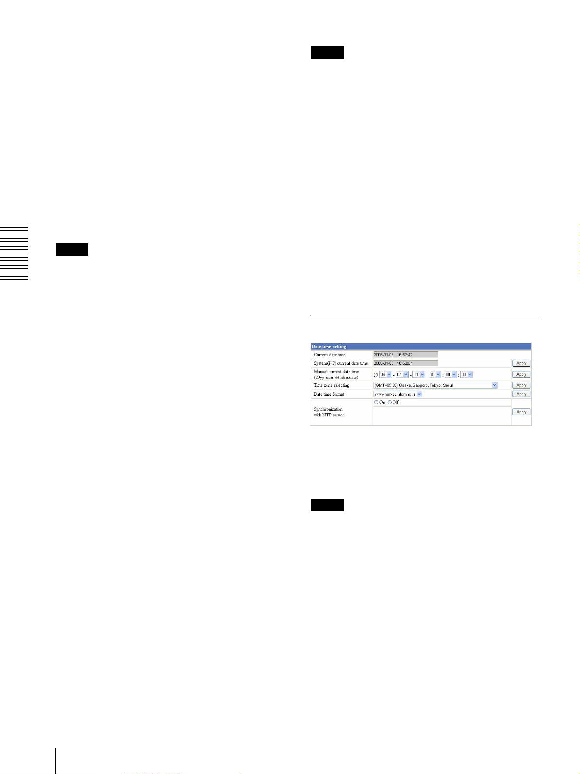
Current date time
Displays the date and time set on this unit.
You can set the date and time using the following two
methods.
Note
When you purchased this unit, be sure to check the date
and time of this unit and set them if necessary.
Maximum wait number
Sets the maximum number of users that can wait to
control the camera while another user is operating the
camera. The selectable number is between 0 and 20.
This setting is valid when the Exclusive control mode
menu is set to On.
14
Configuring the System — System setting Page
System (PC) current date time
Displays the date and time set on your computer.
Click Apply to transfer the computer’s date and time to
this unit.
The set date and time are shown on Current date time.
Manual current date time
When you want to set this unit’s date and time manually.
Select the lower 2-digits of the year, month, date, hour,
minutes and seconds from each drop-down list. Click
Apply to update the Current date time setting to the date
and time you selected.
Page 15

Time zone selecting
Set the time difference from Greenwich Mean Time in
the area where this unit is installed. When you send an
E-mail, the senting date and time is adjusted according
to this setting.
Select the time zone where this unit is installed from the
drop-down list. Click Apply to update the Current date
time setting according to the selection.
Notes
• If the time zone selected on the Time zone selecting
menu is different from that set on the computer, the
time is adjusted using the time zone difference and set
on this unit.
• Due to the network properties, there may be a slight
difference between the actual time and the time set on
this unit.
Date time format
Select the format of date and time to be displayed on the
monitor image from the drop-down list.
You can select from among yyyy-mm-dd hh:mm:ss
(year-month-day hour:minute:second), mm-dd-yyyy
hh:mm:ss (month-day-year hour:minute:second), and
dd-mm-yyyy hh:mm:ss (day-month-year
hour:minute:second).
Click Apply to transfer the setting to this unit.
Synchronization with NTP server
Synchronizes this unit's time with that of the NTP
(Network Time Protocol) server.
Select On to activate the time synchronization, and Off
to deactivate it.
NTP server name
Type the host name or IP address of the NTP server, up
to 64 characters.
This setting is valid when the Synchronization with NTP
server menu is set to On.
Initialization Section
Backup setting
Saves the setting data of this unit in a file.
Click Save, and follow the instructions on the browser to
specify the folder and save the setting data of this unit.
The file name preset at the factory is “snc-dp10.cfg.”
Restore setting
Loads the stored setting data of this unit.
Click Browse and select the file in which the setting data
is stored. Then, click Apply, and this unit is adjusted
according to the loaded data and restarted.
Note
The IP address setting in the Wired LAN setting section
(see page 20) on the Network setting page cannot be set.
Reboot
Reboots this unit.
Click Reboot, and “The SNC-DP10 will be rebooted.
Are you sure?” appears. Click OK to reboot this unit.
Factory default
Resets this unit to the factory settings.
Click Factory default, and “All configuration
information will be initialized as factory setting. Are
you sure?” appears. Click OK to reset to the factory
settings.
Administrating the Camera
Interval time
Select the interval at which you want to adjust this unit's
time referring to the NTP server' time, between 1 and 24
hours. The set interval is a guide, and does not indicate
the exact time.
This setting is valid when the Synchronization with NTP
server menu is set to On.
Note
The time adjusted by this function may be slightly in
error depending on the network environments between
this unit and the NTP server.
Configuring the System — System setting Page
15
Page 16
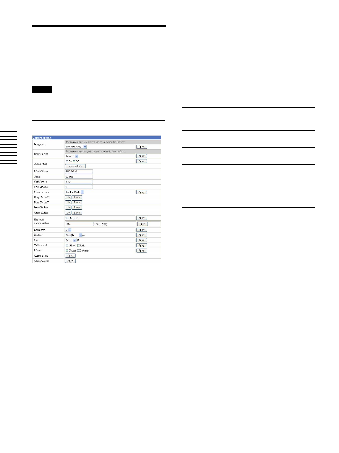
Image quality
Setting the Camera
— Camera setting Page
When you click Camera on the Administrator menu,
the Camera setting page appears.
Use this page to set the functions of the camera.
Note
To update for the changed setting, click Apply on the
changed item.
Camera setting Section
Administrating the Camera
Select the image quality from Level 1 to Level 10.
A higher level gives a higher image quality. According
to the condition of the communication line, the frame
rate may be reduced.
Tip
The following table shows the relation between the data
size of a 24-bit image (8 bits for each R, G and B), and
the compression rate for each Level setting.
(in case of 640 × 480 image)
Level Data size (approx.) Compression rate
(approx.)
1 15 KB 1/60
2 18 KB 1/50
3 22.5 KB 1/40
4 25.7 KB 1/35
5 30 KB 1/30
6 36 KB 1/25
7 45 KB 1/20
8 60 KB 1/15
9 90 KB 1/10
10 180 KB 1/5
Image size
Select the size of the image to be transmitted to the
computer.
You can select from among the following options.
For the NTSC camera:
704 × 480 (Auto), 704 × 480 (Frame), 704 × 480
(Field), 640 × 480 (Auto), 640 × 480 (Frame), 640 ×
480 (Field), 320 × 240, 160 × 120
For the PAL camera:
704 × 544 (Auto), 704 × 544 (Frame), 704 × 544
(Field), 640 × 480 (Auto), 640 × 480 (Frame), 640 ×
480 (Field), 320 × 240, 160 × 120
Frame is suitable for still images, and Field is suitable
for animation.
If you select Auto, the image mode changes between
Frame and Field automatically: Frame when the
subject is a still object, and Field when the subject is
moving.
Area setting
When the image size is 704 × 480 or 640 × 480 for the
NTSC camera, or 704 × 544 or 640 × 480 for the PAL
camera, you can trim a portion of the image and display
the trimmed image on the computer. With the trimming,
the transmitting data size, and thus, the network load is
reduced and a higher frame rate is achieved.
Select On for trimming the image, or Off for no
trimming.
To trim an image
1
Set the Image size menu to 704 × 480 or 640 × 480
for the NTSC camera, or 704 × 544 or 640 × 480 for
the PAL camera.
2
Set the Area setting menu to On, and click Apply.
3
Click the Area setting button.
A still image is displayed.
4
Click on the still image to specify the trimming
portion.
A red frame that appears when you clicked
indicates the trimming portion.
16
Setting the Camera — Camera setting Page
Page 17
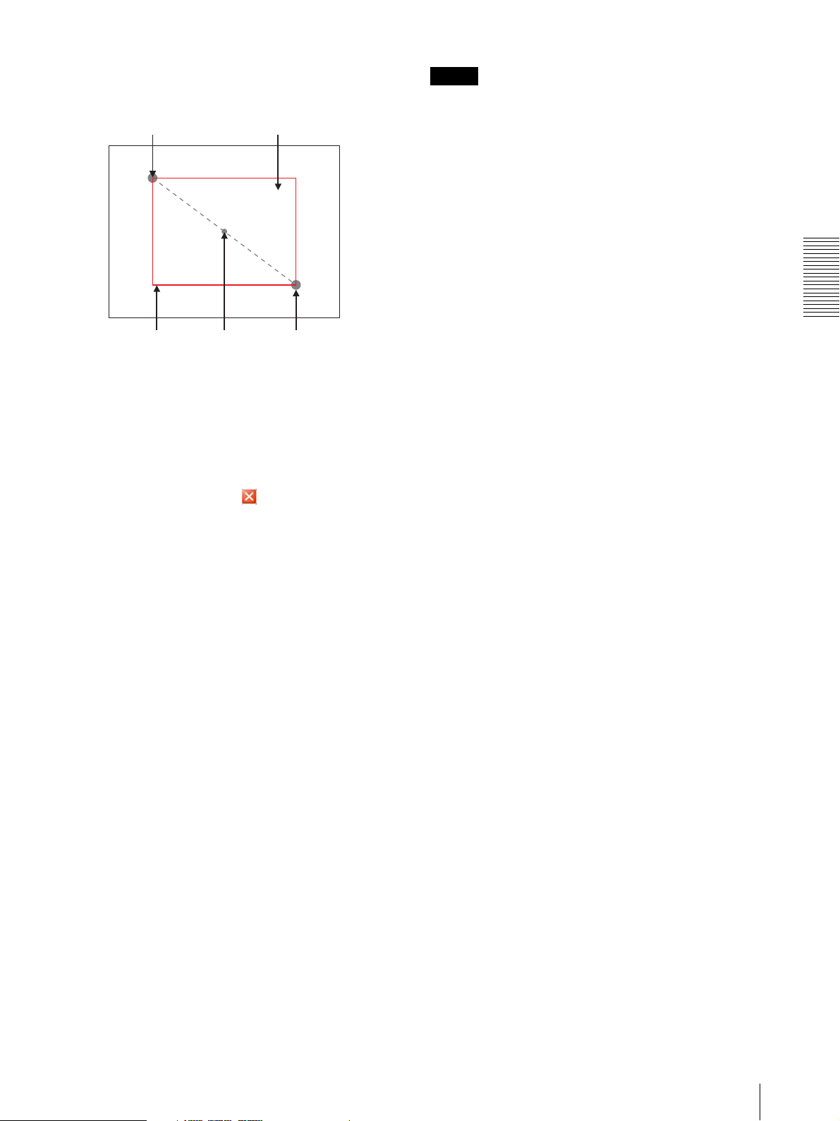
The trimming portion is determined as shown
below:
Point rotated by 180° around the
axis of the center of the still image
Still image
Tip
The green spot and circle displayed during Ring mode
show the center spot and display range used in
DualHalfWide mode. They cannot be turned off.
Ring CenterX
Decide the left and right position of the center spot to
make the flat image of DualHalfWide. This setting is
valid when the Camera mode is set to Ring.
You do not normally have to change the default setting.
Up: Moves to the right.
Down: Moves to the left.
Red trimming
frame
To change the trimming portion, click on another
point on the image.
5
Click OK at the bottom of the window.
The trimmed image is displayed on the main
viewer.
6
To close the image, click on the upper-right
corner.
Center of the
still image
Clicked point
Model Name
The model name of this model "SNC-DP10" is
displayed.
Serial
The serial number of this model is displayed.
Soft version
The version of the software installed in this model is
displayed.
CamModule
The number of the 360-degree camera unit installed in
this model is displayed.
Camera mode
Select the display mode of the image output from the
analog video output of the camera and the one sent to the
computer.
Ring: Displays a 360-degree image without
modification.
DualHalfWide: The image of Ring is displayed flat,
divided into two 180-degree parts, and displayed
above and below.
Ring CenterY
Decide the above and below position of the center spot
to make the flat image of DualHalfWide. This setting
is valid when the Camera mode is set to Ring.
You do not normally have to change the default setting.
Up: Moves downward.
Down: Moves upward.
Inner Radius
Decide the inner trimming position (the inner green line
at Ring image) to make the flat image of
DualHalfWide. This setting is valid when the Camera
mode is set to Ring.
You do not normally have to change the default setting.
Up: The trimming circumference increases.
Down: The trimming circumference decreases.
Outer Radius
Decide the outer trimming position (the outer green line
at Ring image) to make the flat image of
DualHalfWide. This setting is valid when the Camera
mode is set to Ring.
You do not normallly have to change the default setting.
Up: The trimming circumference increases.
Down: The trimming circumference decreases.
Exposure compensation
Adjust the exposure according to the brightness of the
object. It can be adjusted from 100 to 900. The bigger
the number, the more sensitive the exposure.
You can set this value for each Mount (installing
direction). In the factory, Ceiling is set to 240 and
Desktop is set to 200.
Sharpness
Set the outline compensation level of the output image.
You can select one of five levels. In the factory, it is set
to 2.
Administrating the Camera
Setting the Camera — Camera setting Page
17
Page 18
Shutter
Select the shutter speed of the electronic shutter. You can
select one of 16 levels from 1/7.5 to 1/10000. In the
factory, it is set to 1/7.5.
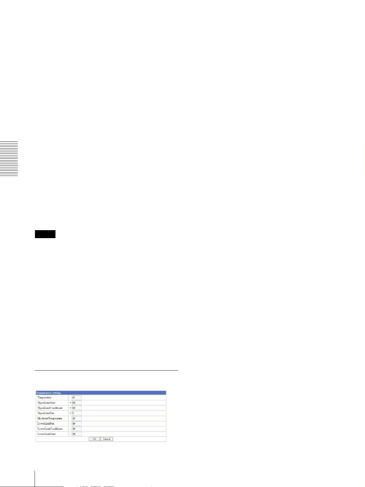
Temperature
The value of the temperature sensor on the basal plate
inside the camera is displayed. The built-in fan is turned
on or off based on this value.
Gain
Select and display the value of the camera AGC (Auto
Gain Control). You can select and display one of 19
levels from 0 to 36 dB.
Your setting will be temporary, because an optimum
level is selected to suit the brightness of the object.
UpperLimitAlert
This value is for internal temperature control.
Do not change it.
UpperLimit Conditioner
This value is for internal temperature control.
Do not change it.
TvStandard
Select the video format of the output video signal from
NTSC and PAL.
When this setting is changed, the camera system
automatically restarts. Internet Explorer must be read
again because the communication line of the computer
is interrupted.
Administrating the Camera
Mount
Select an installation form of the camera from Ceiling
and Desktop. When Ceiling is selected, the image from
the analog video output and the image sent to the
computer are turned around.
Note
In this viewer, the image may be turned around in the
display when the viewer is started up with Mount of
Camera section set to Desktop. This image is not
corrected if you set it to be turned around in Mount
setting.
When you use the camera with Desktop installation, we
recommend using the viewer ActiveX viewer.
UpperLimitFan
This value is for internal temperature control.
Do not change it.
ModerateTemperature
This value is for internal temperature control.
Do not change it.
LowerLimitFan
This value is for internal temperature control.
Do not change it.
LowerLimit Conditioner
This value is for internal temperature control.
Do not change it.
LowerLimitAlert
This value is for internal temperature control.
Do not change it.
Camera save
Save the setting contents for the camera in the flash
memory inside the camera.
Camera reset
Reset the setting contents for the camera to return them
to the factory settings.
Temperature setting section
18
Setting the Camera — Camera setting Page
OK/Cancel
See “Buttons common to every setting page” on page
12.
Page 19
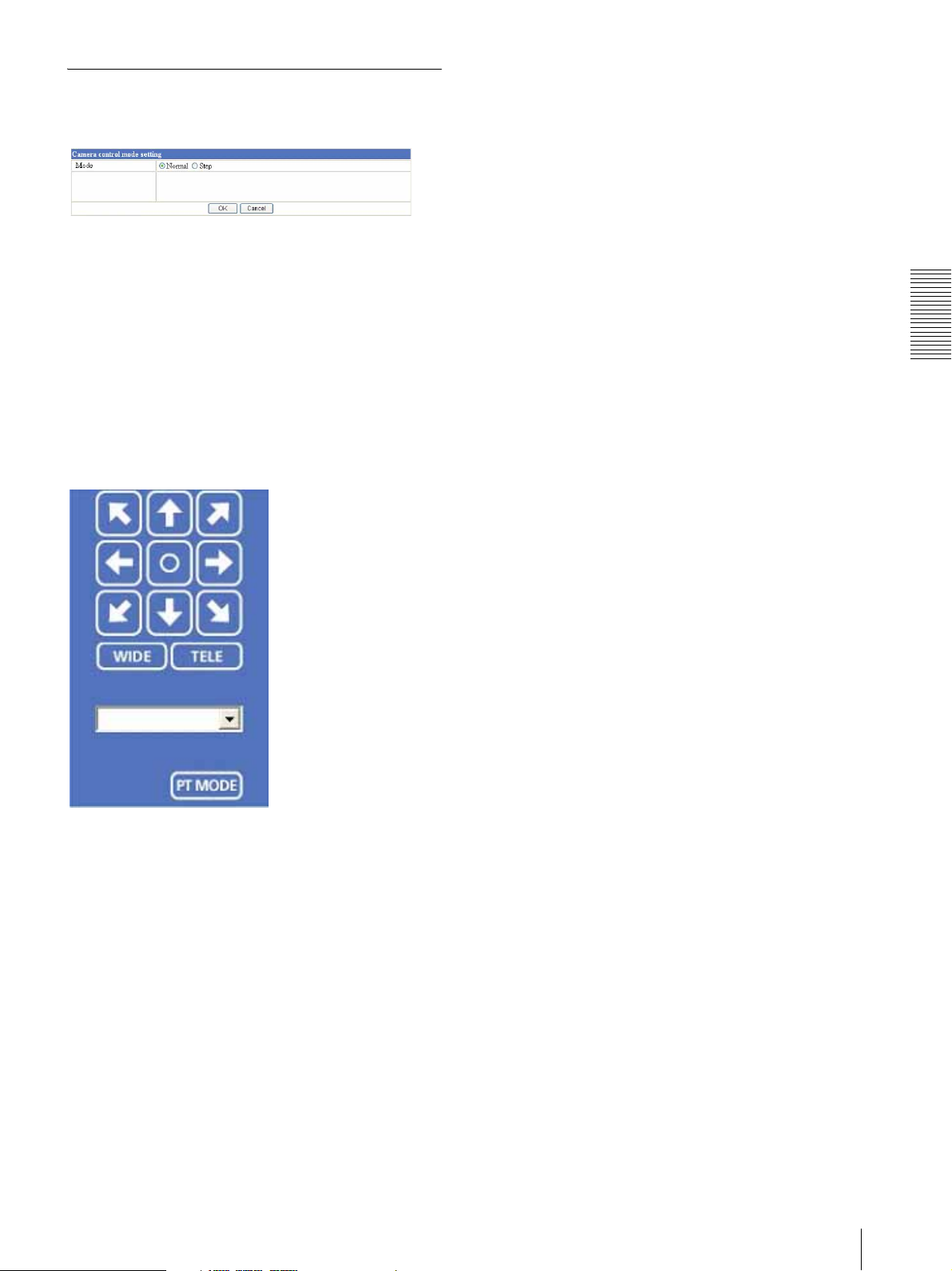
Camera control mode setting section
Mode
Select the answer level of when you use the arrow button
of the control panel. When you press Step, the answer
levels are displayed and you can select one of them. But
their use is limited in this camera. (Refer to "Control
panel" below.)
Control panel
Select the display direction and display mode of
direction of the camera. This setting is valid when the
Camera mode is set to DualHalfWide.
OK/Cancel
See “Buttons common to every setting page” on page
12.
Administrating the Camera
Directional arrow: The center of the display can be
moved left or right when DualHalfWide mode is
selected. It does not respond to an up or down
command.
Central round: The center moved by the Directional
button is placed back to the point of factory default.
WIDE/TELE: It cannot be used in this camera.
Radio selector: When you select home, the center
moved by the Directional button is placed back to the
point of factory default.
PT MODE: It switches Directional arrow display mode
and Tablet display mode. In Tablet display mode,
only an operation toward left or right is active in
common with Directional arrow mode.
Setting the Camera — Camera setting Page
19
Page 20
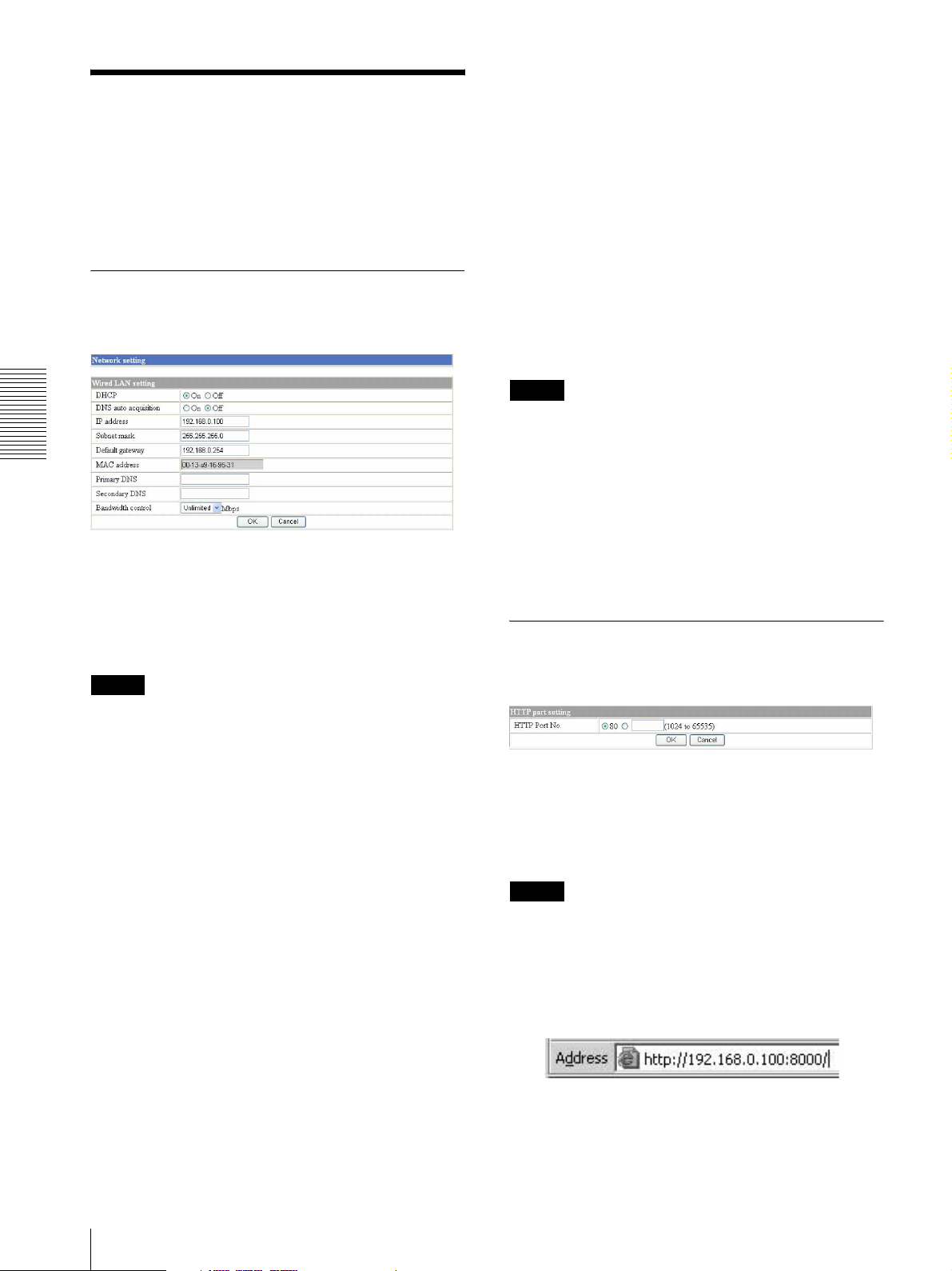
Configuring the Network
Primary DNS
Type the IP address of the primary DNS server.
— Network setting Page
When you click Network on the Administrator menu,
the Network setting page appears.
Use this page to configure the network to connect this
unit and the computer.
Wired LAN setting Section
This section provides the menus for connecting this unit
through the network cable.
Administrating the Camera
Secondary DNS
Type the IP address of the secondary DNS server, if
necessary.
Bandwidth control
Limits the data communication bandwidth for this unit.
You can select from among the following:
Unlimited, 0.5, 0.6, 0.7, 0.8, 0.9, 1.0, 2.0, 3.0, 4.0, 5.0,
6.0, 7.0, 8.0 (Mbps)
Select Unlimited when you do not want to limit the
bandwidth.
Notes
• If you limit the bandwidth, this unit performance may
be affected, for example, the frame rate of image
display may be reduced.
• The actual bandwidth may differ from the selected
option depending on the network environments.
OK/Cancel
See “Buttons common to every setting page” on page
DHCP
Select On to assign the IP address to this unit
automatically. When you have assigned a proper IP
address to this unit, select Off.
Note
When you set DHCP to On, make sure that there is an
DHCP server on the network.
12.
HTTP port setting Section
You can set the port number for the HTTP server on this
unit.
DNS auto acquisition
When DHCP is set to On, select if the IP address of the
DNS server is assigned automatically or not. Select On
to assign the IP address of the DNS server automatically.
IP address
Type the IP address of this unit.
Subnet mask
Type the subnet mask.
Default gateway
Type the default gateway.
MAC address
Displays the MAC address of the camera.
20
Configuring the Network — Network setting Page
HTTP port No.
Normally select 80. If you want to use a port number
other than 80, select the text box and type a port number
between 1024 and 65535.
Note
When you have set the HTTP port No. to a number other
than 80 on the Network setting page or in the Setup
Program, access this unit by typing the IP address of this
unit on the web browser, as follows:
Example: when HTTP port No. is set to 8000
OK/Cancel
See “Buttons common to every setting page” on page
12.
Page 21
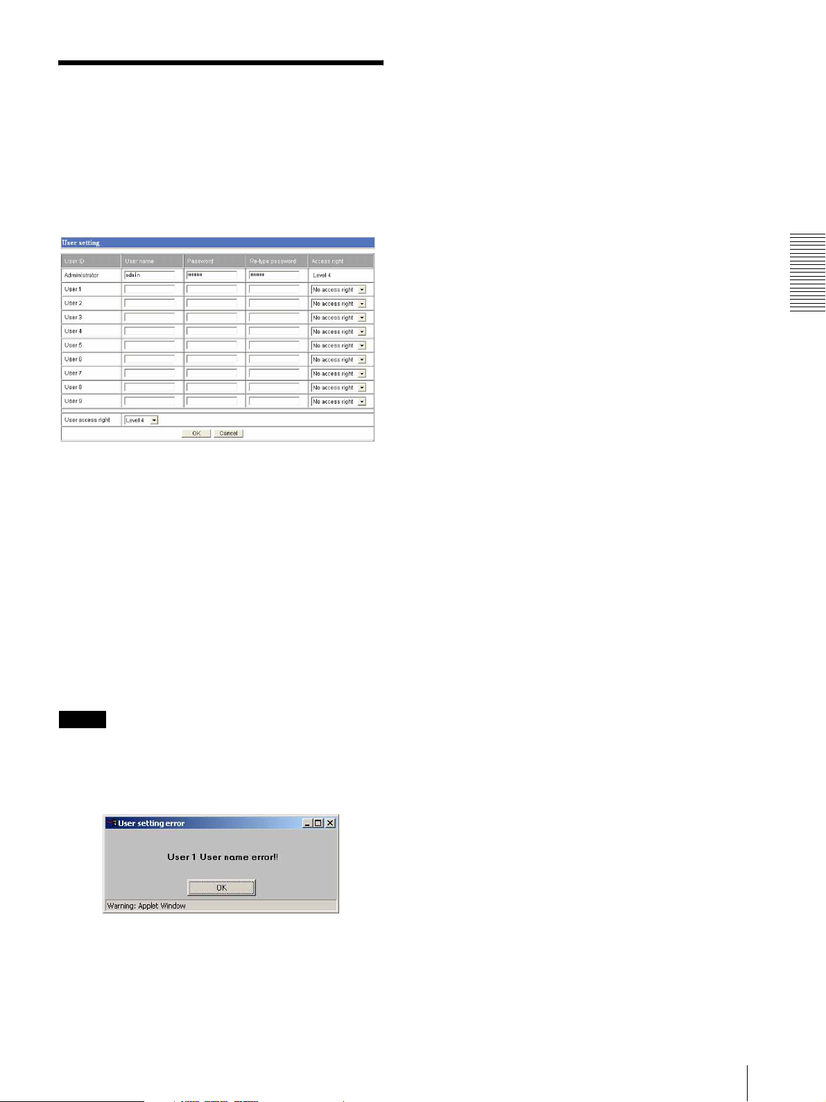
Setting the User
— User setting Page
Access right
Select the access right for each user from the drop-down
list. The rights afforded to each access right are as
follows:
When you click User on the Administrator menu, the
User setting page appears.
Use this page to set the user names and passwords of
Administrator and up to 9 kinds of users (User 1 to User
9), and the access right of each user.
Administrator, User 1 to 9
Specify User name, Password, Re-type password and
Access right for each user ID.
User name
Type a user name between 4 and 16 characters.
Password
Type a password between 4 and 16 characters.
Level 1 - Level 3: Allows monitoring of the camera
image and capturing the display.
Level 4: Allows all the access right as Administrator.
No access right: Use this option when you want to
prohibit access to this unit temporarily.
User access right
Select the level of the access right to require user
authentication.
The authentication dialog will appear where user
authentication is required.
Lvele 1: Performs user authentication when a user
accesses all pages.
Lvele 2 - Level 3: Performs user authentication when a
user accesses the Administrator setting menu page.
Lvele4: No user authentication is required to display
pages.
OK/Cancel
See “Buttons common to every setting page” on page
12.
Administrating the Camera
Re-type password
To confirm the password, type the same characters as
you typed in the Password box.
Note
If you type an incorrect character in the User name,
Password or Re-type password box, a message like the
following appears. In this case, click OK to cancel the
message and re-type the correct character.
Setting the User — User setting Page
21
Page 22
Setting the Security
— Security setting Page
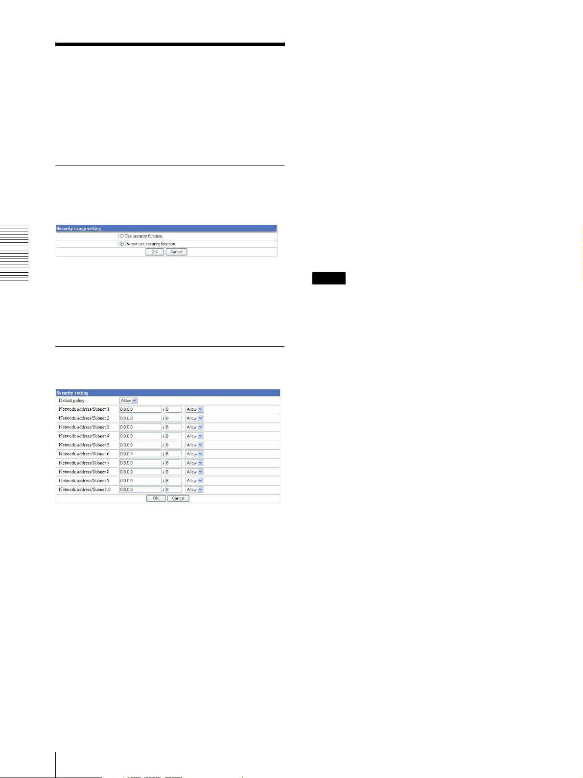
When you click Security on the Administrator menu,
the Security setting page appears.
Use this page to limit the computers that can access this
unit.
Network address/Subnet 1 to Network
address/Subnet 10
Type the IP addresses and subnet mask values you want
to allow or deny access to this unit.
You can specify up to 10 IP addresses and subnet mask
values. For a subnet mask, type 8 to 32.
To temporarily cancel the Default Policy for a specified
IP address/subnet mask, select Allow or Deny from the
drop-down list on the right.
Activating/Deactivating the
Security Function
— Security usage setting Page
To activate the security function, select Use security
Administrating the Camera
function, then click OK. The Security setting page
appears.
If you do not use the security function, select Do not use
security function, then click OK.
Setting the Security Function
—Securing setting Page
Tip
The subnet mask value represents the bit number from
the left of the network address.
For example, the subnet mask value for 255.255.255.0 is
24.
If you set “192.168.0.0/24, Allow,” you can allow access
from the computers having an IP address between
192.169.0.0 and 192.168.0.255.
Note
You can access this unit even from a computer having
the IP address whose access right is set to Deny, if you
enter the user name and password set for Level 4 access
right on the authentication dialog displayed.
OK/Cancel
See “Buttons common to every setting page” on page
12.
Default policy
Select the basic policy of the limit from Allow and
Deny.
If you select Allow, you will basically allow access to
this unit and only deny access from the computers
specified on the Network address/Subnet 1 to Network
address/Subnet 10 menus.
If you select Deny, you will basically deny access to this
unit, and only allow access from the computers specified
on the Network address/Subnet 1 to Network address/
Subnet 10 menus.
22
Setting the Security — Security setting Page
Page 23
Sending Images to FTP
Server
— FTP client setting Page
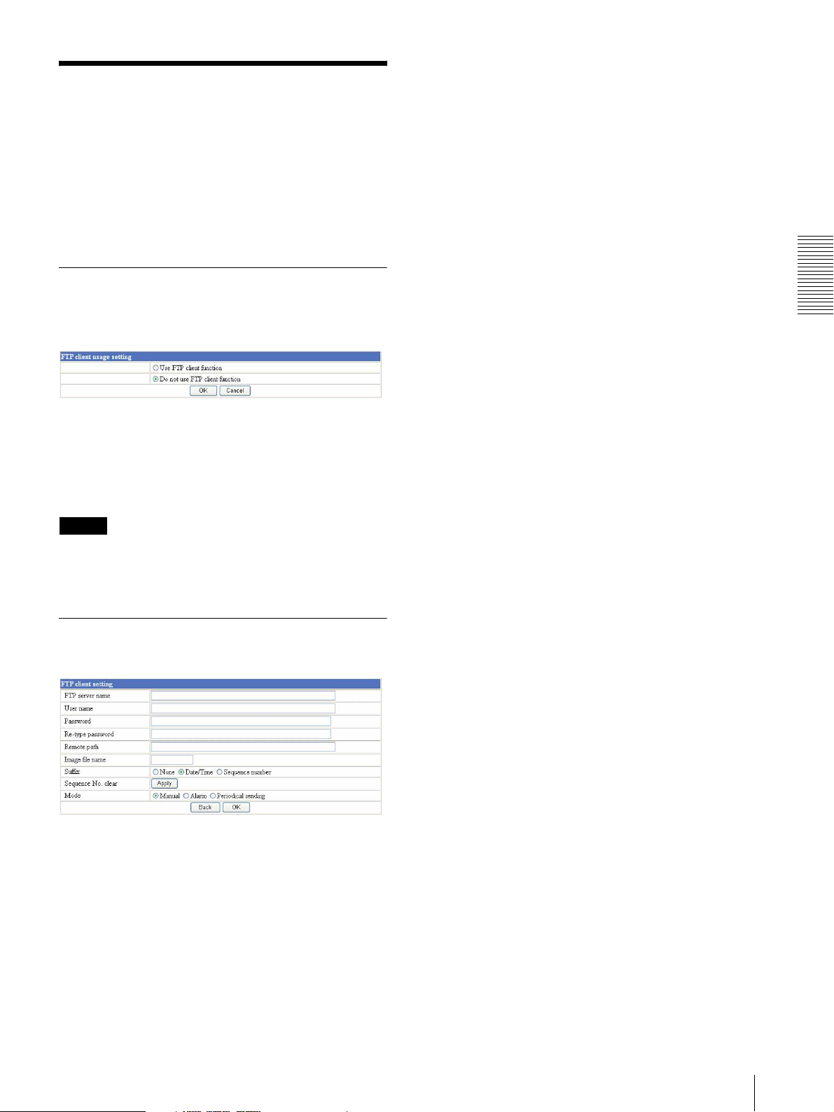
When you click FTP client on the Administrator menu,
the FTP client setting page appears.
Use this page to set up for capturing and sending still
images to an FTP server.
Activating/Deactivating the FTP
Client Function
— FTP client usage setting Page
Re-type password
To confirm the password, type the same characters as
you typed in the Password box.
Remote path
Type the path to the destination up to 64 characters.
Image file name
Type the basic file name you want to assign to the
images when sending to the FTP server. You can use up
to 6 alphanumeric, - (hyphen) and _ (underscore) for
naming.
Suffix
Set the suffix to add to the file name.
Select None.
Date/Time and Sequence number are not active in this
camera.
Administrating the Camera
To activate the FTP client function, select Use FTP
client function and click OK. The FTP client setting
page appears.
When you do not use the FTP client function, select Do
not use FTP client function and click OK.
Note
The frame rate and operability on the main viewer may
decrease while a file is being transmitted by the FTP
client function.
Setting the FTP Client Function
— FTP client setting Page
Sequence No. clear
It is not active in this camera.
Mode
Set the mode of the FTP client function.
Select Manual in the initial setting.
Alarm and Periodical sending are not active in this
camera.
Back/OK
See “Buttons common to every setting page” on page
12.
FTP server name
Type the FTP server name to upload still images up to 64
characters, or the IP address of the FTP server.
User name
Type the user name for the FTP server.
Password
Type the password for the FTP server.
Sending Images to FTP Server — FTP client setting Page
23
Page 24
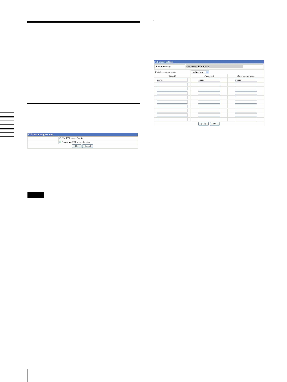
Setting the FTP Server Function
Downloading Stored
Images
— FTP server setting Page
When you click FTP server on the Administrator menu,
the FTP server setting page appears.
Use this page to set up for the FTP server function which
finds a specified still image file stored in the built-in
memory of this unit (about 8 MB) or download the still
image file from the card.
— FTP server setting Page
You can register up to 10 user names and passwords to
allow logging in this unit using the FTP client software
of the computer.
Activating/Deactivating the FTP
Server Function
— FTP server usage setting Page
Built-in memory
Administrating the Camera
Displays the free space of the built-in memory of this
unit.
To activate the FTP server function, select Use FTP
server function and click OK. The FTP server setting
page appears.
When you do not use the FTP server function, select Do
not use FTP server function and click OK.
Note
The frame rate and operability on the main viewer page
may decrease when the FTP server function is used.
OK/Cancel
See “Buttons common to every setting page” on page
12.
Selected root directory
Built-in memory is displayed in this camera. There is
no alternative.
User ID
Type a user name between 4 and 16 characters.
Password
Type a password between 4 and 16 characters.
Re-type password
To confirm the password, type the same characters as
you typed in the Password box.
Back/OK
See “Buttons common to every setting page” on page
12.
24
Downloading Stored Images — FTP server setting Page
Page 25
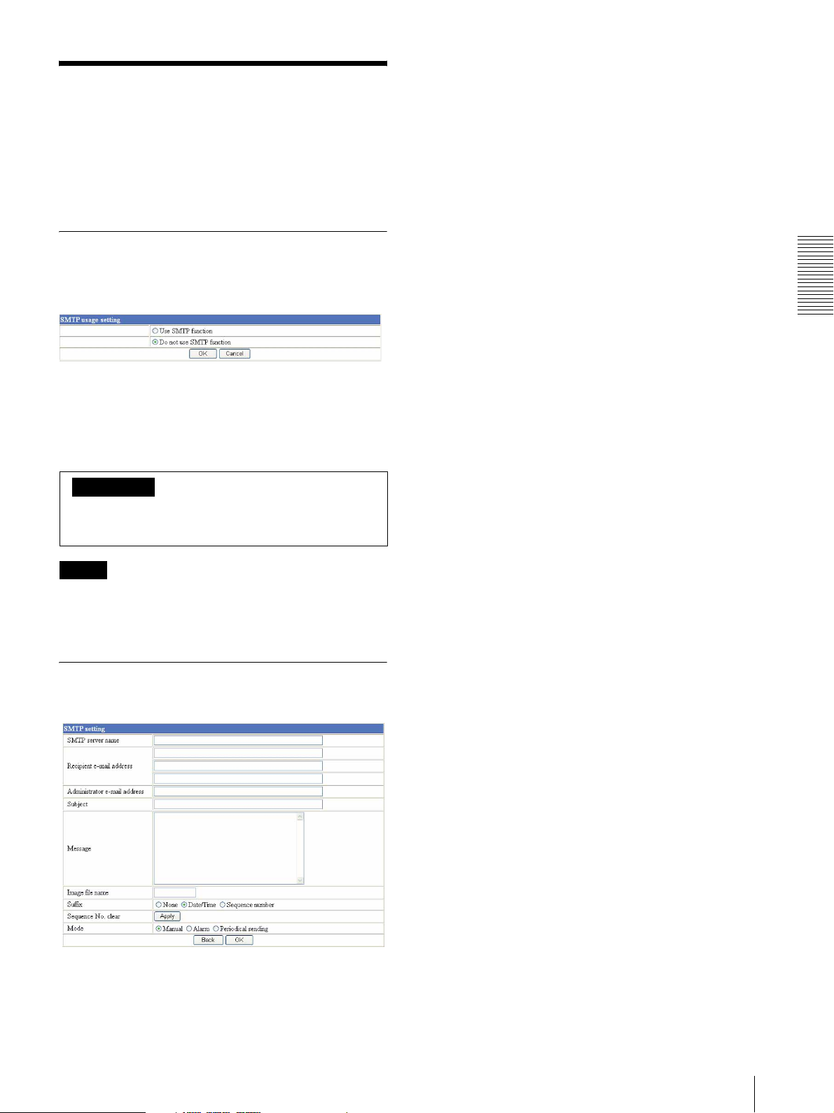
Sending an Image via Email
When you click SMTP on the Administrator menu, the
SMTP setting page appears.
Use this page to set up for the SMTP function that can
capture and send a still image attached to an E-mail.
— SMTP setting Page
Recipient e-mail address
Type the recipient E-mail address up to 64 characters.
You can specify up to three recipient E-mail addresses.
Administrator e-mail address
Type the Administrator e-mail address up to 64
characters.
This address is used for reply mail and sending error
messages from this unit.
Activating/Deactivating the SMTP
Function — SMTP usage setting
Page
To activate the SMTP function, select Use SMTP
function and click OK. The SMTP setting page
appears.
When you do not use the SMTP function, select Do not
use SMTP function and click OK.
Important
If you select Use SMTP function, the inside fan stops or the
temperature increases more than usually, then a mail is sent
to make this known.
Note
The frame rate and operability on the main viewer may
decrease while an image file is being transmitted via an
E-mail.
Setting the SMTP Function
— SMTP setting Page
Subject
Type the subject/title of the E-mail up to 64 characters.
Message
Type the text of the E-mail up to 384 characters. (A line
break is equivalent to 2 characters.)
Image file name
Type the basic file name you want to assign to the image
to attach an E-mail. You can use up to 6 alphanumeric,
- (hyphen) and _ (underscore) for naming.
Suffix
Set the suffix to add to the file name.
Select None.
Date/Time and Sequence number are not active in this
camera.
Sequence No. clear
It is not active in this camera.
Mode
Set the mode of the SMTP function.
Select Manual in the initial setting.
Alarm and Periodical sending are not active in this
camera.
Administrating the Camera
SMTP server name
Type the SMTP server name up to 64 characters, or the
IP address of the SMTP server.
Back/OK
See “Buttons common to every setting page” on page
12.
Sending an Image via E-mail — SMTP setting Page
25
Page 26
Others
Using the Supplied Setup Program
The “File Download” dialog opens.
3
Click Open.
Note
If you click “Save this program to disk” on the “File
Download” dialog, you will not be able to perform
set up correctly. Delete the downloaded file, and
click the Setup icon again.
To connect the camera to a network, you need to assign
a new IP address to the camera when you install it for the
first time.
You can assign an IP address in two ways:
• Using the setup program stored in the supplied CDROM (see this page)
• Using the ARP (Address Resolution Protocol)
commands (see page 29)
This section explains how to assign an IP address to the
camera using the supplied setup program and how to
Others
configure the network.
Before starting, connect the camera to a local network,
referring to “Connecting the Camera to a Local
Network” in the supplied Installation Manual.
Consult the administrator of the network about the
assigned IP address.
Notes
• The Setup Program may not operate correctly if you
use a personal firewall or antivirus software in your
computer. In that case, disable the software or assign
an IP address to the camera using another method. For
example, see “Assigning the IP Address to the Camera
Using ARP Commands” on page 29.
• It you are using Windows XP Service Pack 2, disable
the Windows Firewall function. Otherwise the IP
Setup Program will not operate correctly.
To disable Windows Firewall, operate as follows:
4
Install the IP Setup Program on your computer
using the wizard.
If the Software License Agreement is displayed,
read it carefully and click Accept to continue with
the installation.
5
Start the IP Setup Program.
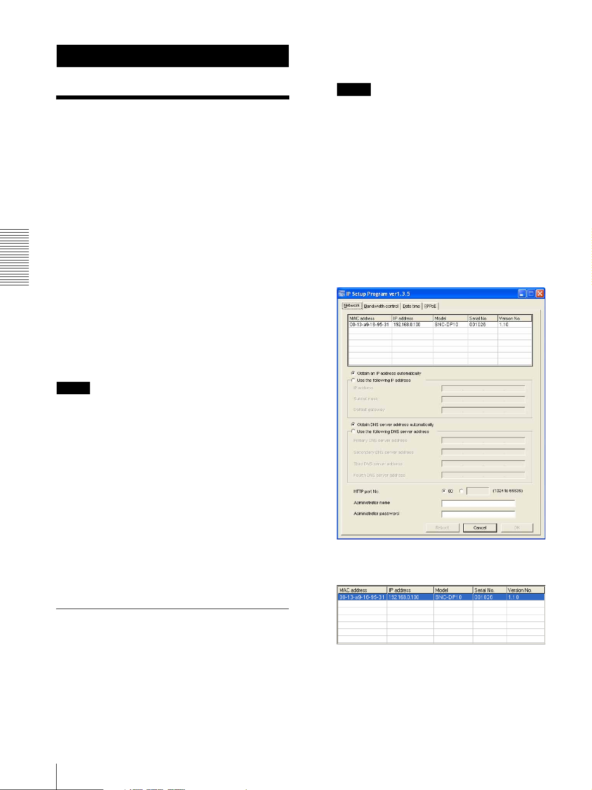
The program detects the network cameras
connected to the local network and lists them on the
Network tab window.
1
Open Windows Firewall from Control Panel.
With the category display, you can find Windows
Firewall in Security Center.
2
Select Off, and click OK.
Assigning an IP address using the Setup Program
1
Insert the supplied CD-ROM disc into your CDROM drive.
After a short time a window will open displaying
the files on the CD-ROM.
2
Click the Setup icon of IP Setup Program.
26
Using the Supplied Setup Program
6
Click on the camera in the list to which you want to
assign a new IP address.
The network settings for the selected camera are
displayed.
7
Set the IP address.
Page 27
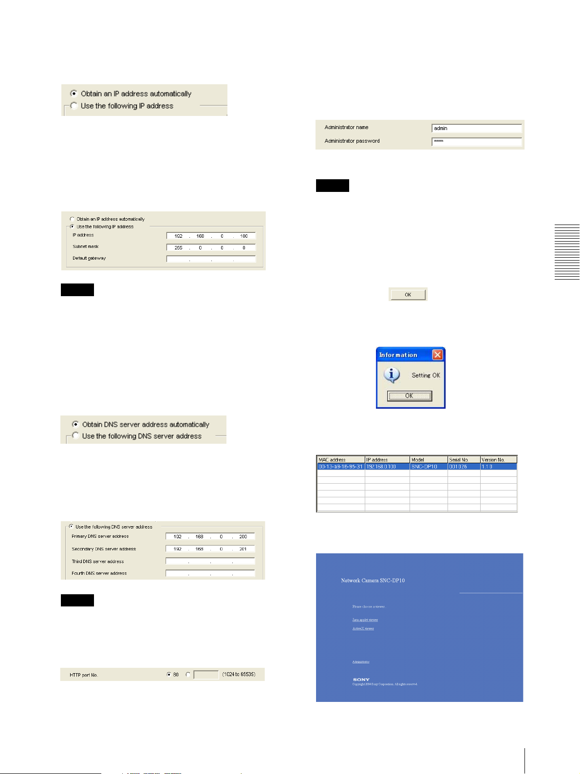
To obtain the IP address automatically from a
DHCP server:
Select Obtain an IP address automatically.
The IP address, Subnet mask and Default gateway
are assigned automatically.
Normally, select 80 for the HTTP port No. To use
another port number, type the port number between
1024 and 65535 in the text box.
10
Type the Administrator name and Administrator
password.
To specify the IP address manually:
Select Use the following IP address, and type the
IP address, Subnet mask and Default gateway in the
relevant boxes.
Note
When you select Obtain an IP address
automatically, make sure that the DHCP server is
operating on the network.
8
Set the DNS server address.
To obtain the DNS server addresses
automatically:
Select Obtain DNS server address automatically.
The factory settings of both items are “admin.”
Note
You cannot change the Administrator name and
Administrator password in this step. To change
these items, see “Setting the User — User setting
Page” on page 21.
11
Confirm that all items are correctly set, then click
OK.
If “Setting OK” is displayed, the IP address is
correctly assigned.
12
To access the camera directly, double-click the
camera name in the list.
Others
To specify the DNS server addresses manually:
Select Use the following DNS server address, and
type the Primary DNS server address and
Secondary DNS server address in the relevant
boxes.
Note
The Third DNS server address and Fourth DNS
server address are invalid for this camera.
9
Set the HTTP port No.
The welcome page of the network camera is
displayed on the web browser.
Using the Supplied Setup Program
27
Page 28
Note
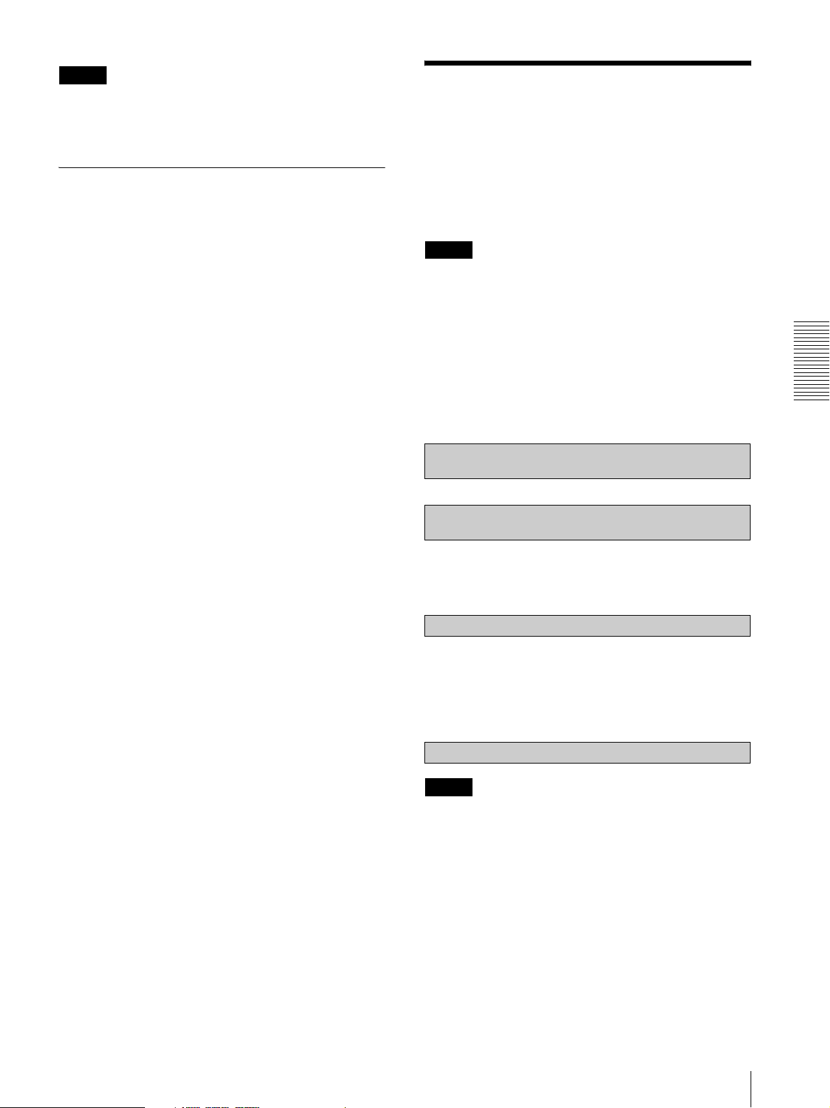
Setting the Date and Time
If the IP address is not set correctly, the welcome page
does not appear after step 12. In that case, try to set the
IP address again.
You can set the date and time on this unit.
1
Click the Date time tab to display the date/time
setting window.
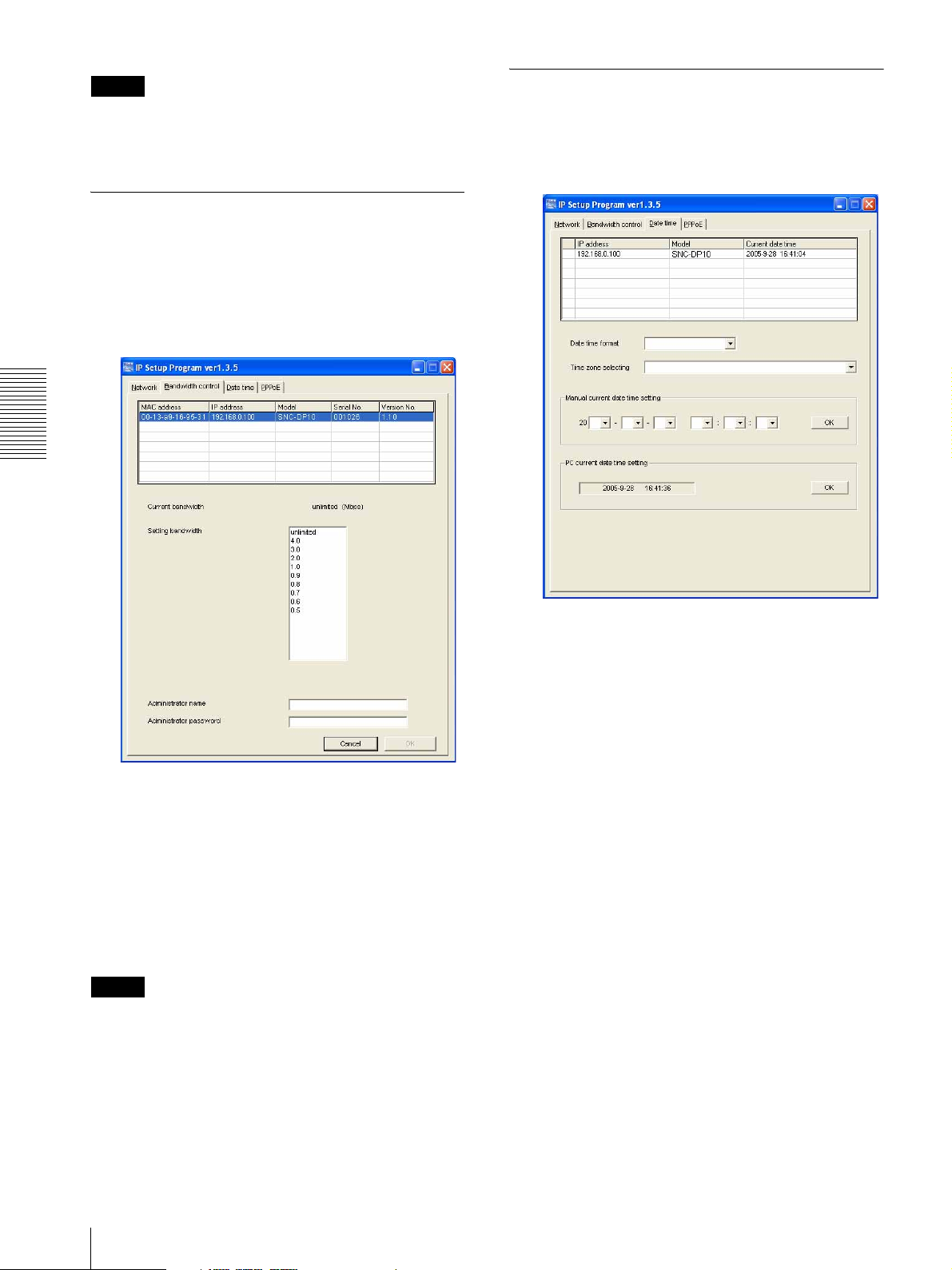
Changing the Communication Bandwidth
1
Click the Bandwidth control tab to display the
bandwidth setting window.
The current bandwidth is displayed in Current
bandwidth.
Others
2
Click to select the desired bandwidth from the
Setting bandwidth list box.
3
Type the Administrator name and Administrator
password in each box.
4
Click OK.
If "Setting OK" is displayed, the bandwidth setting
is completed.
Note
The contents of the bandwidth changed in "IP Setup
Program" are reflected to Bandwidth control in the
Network setting page (page 20).
2
Click to select the SNC-DP10 you want to set the
date and time for.
3
Select the date/time format from the Date time
format drop-down list.
4
Select the area where the SNC-DP10 is installed
from the Time zone selecting drop-down list.
5
Set the date and time.
You can set the date and time in two ways.
Manual setting
Set the current date and time on the Manual current
date time setting boxes, and click OK. The setting
boxes are for the year (lower two digits), month,
date, hour, minutes and seconds from left to right.
Using the computer’s date and time
The date and time set on the computer is displayed
in the PC current date time setting box.
Click OK on the right to set the date and time of
SNC-DP10 to the displayed computer's date and
time.
28
Using the Supplied Setup Program
Page 29
Note
Due to the network properties, there may be a slight
difference between the displayed computer's date and
time and those set on the SNC-DP10.
Assigning the IP Address to the Camera Using ARP Commands
Rebooting the SNC-DP10
Click Reboot on the Network tab to reboot the SNCDP10.
It will take about 10 to 20 seconds to reboot.
This section explains how to assign an IP address to the
camera using ARP (Address Resolution Protocol)
commands without using the supplied setup program.
Note
When you turn on the camera, execute the ARP and
PING commands within 5 minutes. Also when you
restart the camera, execute the operation within 5
minutes.
1
Open the command prompt on the computer.
2
Enter the IP address and the MAC address of the
camera to assign a new IP address, using the
following ARP commands.
arp -s <Camera's IP address> <Camera's MAC address>
ping -t <Camera's IP address>
Example:
arp -s 192.168.0.100 08-00-46-21-00-00
ping -t 192.168.0.100
3
When the following line is displayed on the
command prompt, hold down Ctrl and press C.
The display stops.
Others
Reply from 192.168.0.100:bytes=32 time...
You will normally receive a reply after about 5
repetitions of “Request time out.”
4
Wait until the execution of PING finishes, then
input the following code.
arp -d 192.168.0.100
Note
If you do not receive a reply, check the following:
– Did you enter the ARP commands within 5 minutes
after it was turned on?
If not, turn off the camera and restart the operation.
– Is the NETWORK indicator on the camera flashing?
If the indicator goes off, the network connection has a
problem. Connect the network correctly.
– Did you enter the IP address previously used for
another device?
Assign a new IP address to the camera.
– Do the computer and the camera have the same
network address?
If not, set the same network address on the computer
and the camera.
Assigning the IP Address to the Camera Using ARP Commands
29
Page 30
Using the SNMP
This unit supports SNMP (Simple Network
Management Protocol). You can read MIB-2 objects
and write some MIB-2 objects using software such as
SNMP manager software. This unit also supports the
coldStart trap which occurs when the power is turned on
or the unit restarts, and the Authentication failure trap
which informs of an illegal access using SNMP.
Using CGI commands, you can set community name
and access limitation, reading/writing right, host to send
traps, and some MIB-2 objects. To allow these settings,
you need authentication by the camera administrator.
4 describes the case of “mib-2.system. sysContact.0”.
This field is used to describe the information on
administrator of this camera. Nothing is set at the
factory.
5 describes the case of “mib-2.system. sysName.0”.
This field is used to describe administration node of
this camera. Nothing is set at the factory.
6 describes the case of “mib-2.snmpEnable
AuthenTraps.0”. This example shows when “1”
(enable) is set. With this setting, a trap occurs when
there is an Authentication failure. When “2”
(disable) is set, no Authentication failure trap
occurs.
1. Inquiry Commands
You can check the SNMP Agent settings using the
following CGI commands.
Others
<Method>
GET, POST
<Command>
http://ip_adr/snmpdconf/inquiry.cgi?inqjs=snmp
(JavaScript parameter format)
http://ip_adr/snmpdconf/inquiry.cgi?inq=snmp
(standard format)
With the above inquiry, you can obtain the following
setting information. The following explains the setting
information using the inqjs=snmp (JavaScript
parameter) format.
var sysDescr=“SONY Network Camera SNC-DP10”
...1
var sysObjectID=“1.3.6.1.4.1.122.8501” ...2
var sysLocation=“” ...3
var sysContact=“” ...4
var sysName=“” ...5
var snmpEnableAuthenTraps=“1” ...6
var community=“public,0.0.0.0,read,1” ...7
var community=“private,192.168.0.101,write,2” ...8
var trap=“public,192.168.0.101.1” ...9
1 describes the case of “mib-2.system. sysDescr.0”.
You cannot change this parameter.
7 describes the community name and the reading/
writing attributes. This example shows the
identification number “ID=1”, the community
name public, and enables read from any IP address
(0.0.0.0).
8 describes the community name and the reading/
writing attributes, similarly to 7. This example
shows the identification number ID=2, the
community name “private”, and enables “read/
write” by the SNMP request packet from the host
“192.168.0.101”.
9 describes the host name to send a trap. This
example shows the identification number “ID=1”,
the community name “public”, and enables sending
of traps to the host having the IP address
“192.168.0.101”.
2. Setting Commands
The unit supports the following setting commands of
SNMP.
<Method>
GET, POST
<Command>
http://ip_adr/snmpdconf/snmpdconf.cgi?
<parameter>=<value>&<parameter>=...&...
First, perform the settings of the following parameters.
2 describes the case of “mib-2.system.
sysObjectID.0”. You cannot change this parameter.
3 describes the case of “mib-2.system.
sysLocation.0”. This field is used to describe
information on the location of this camera. Nothing
is set at the factory.
30
Using the SNMP
1) sysLocation=<string>
Set the case of “mib-2.system.sysLocation.0” in the
<string> position. The maximum length of
<string> is 255 characters.
2) sysContact=<string>
Set the case of “mib-2.system.sysContact.0” in the
<string> position. The maximum length of
<string> is 255 characters.
Page 31
3) sysName=<string>
Set the case of “mib-2.system.sysName.0” in the
<string> position. The maximum length of
<string> is 255 characters.
4) enaAuthTraps=<value>
Set the case value of “mib-2.snmp.snmp
EnableAuthenTraps.0” in the <string> position.
Type “1” (enable) or “2” (disable) in the <value>
position.
5) community=<ID>,<rwAttr>,
<communityName>,<IpAddressString>
Set the community name and the reading/writing
attributes. <ID> describes the setting identification
number (1 to 8), <rwAttr> describes a character
representing the reading/writing attribute (“r”, “R”,
“w or “W”), <communityName> describes the
community name to be set, and <IpAddressString>
describes the IP address of the host you allow
access (0.0.0.0 for any host).
Example: To allow reading/writing by any host in the
“private” community and having the ID number “2”.
community=2,w,private,0.0.0.0
<Command>
http://ip_adr/snmpdconf/snmpdconf.cgi?
snmpd=restart
Others
6) trap=<ID>,<communityName>,
<IpAddressString>
Set the host you want to send traps to. <ID>
describes the setting identification number (1 to 8),
<communityName> describes the community
name to send traps to, and <IpAddressString>
describes the IP address of the host to send traps to.
Example: To specify the destination of traps as the
public community and the ID number “1”.
trap=1,public,192.168.0.101
7) delcommunity=<ID>
This parameter is used to delete the previous
community setting. <ID> describes the community
setting identification number (1 to 8).
8) deltrap=<ID>
This parameter is used to delete the previous setting
of the host to send traps to. <ID> describes the trap
setting identification number (1 to 8).
When you have finished changing the SNMP setting
information using the above parameters 1) to 8), check
the changed settings using an inquiry commands. If the
changed settings are OK, restart the SNMP using the
following CGI command.
SNMP restart command
<Method>
GET, POST
Using the SNMP
31
Page 32
Horizontal resolution
Specifications
Signal-to-noise ratio
Network
Protocol TCP/IP, ARP, ICMP, HTTP, FTP
(server/client), SMTP (client),
DHCP (client), DNS (client), NTP
(client), SNMP (MIB-2)
Compression
Video compression format
Minimum illumination
AGC Switchable automatically
Exposure control
Electronic shutter
JPEG
Image size NTSC: 704 × 480, 640 × 480, 320 ×
240, 160 × 120
PAL: 704 × 544, 640 × 480, 320 × 240,
160 × 120
Maximum frame rate
JPEG: 30 fps
1) This value indicates the maximum
Others
number of frames that can be
transmitted. The number of frames
actually transmitted may vary
depending on network environments
and camera settings (image size and
image quality settings).
1)
(VGA)
Web browser Internet Explorer Ver. 5.5 or 6.0
White balance ATW
BLC Switchable automatically
Interface
Network port 10BASE-T/100BASE-TX (RJ-45)
Video output BNC connector (extended from the
Others
Power supply 12 V DC ± 2 V
Power consumption
(Available OS: Windows 2000/ XP)
Computer environments
Operating temperature
CPU: Pentium III, 1 GHz or higher
(Pentium 4, 2 GHz or higher
recommended)
RAM: 256 MB or more
Display size: 1024
× 768
Maximum user access
JPEG mode: 10 users
Network security
Password (basic authentication), IP
filtering
Other functions
Image trimming, built-in clock, etc.
480 TV lines (analog video)
50 dB (AGC OFF, Weight On) (analog
video)
0.3 lux
AUTO iris
CCD Iris
(extended from the multi cable)
multi cable)
1.0 Vp-p, 75 ohms, unbalanced,
sync negative
24 V DC ± 2 V
10 W max.
-20 °C to +50 °C [-4 °F to +122 °F] for
continuous operation
-5 °C to +50 °C [23 °F to 122 °F] for
starting the unit
2) When the operating temperature is
around -20 °C, the camera image may be
noisy.
3) If you turn on the power of the unit at
temperatures lower than -5 °C (23 °F),
the unit may not start. In this case, warm
the unit and turn it on again. Be sure to
wait for several seconds between
turning off and turning on the unit.
2)
3)
Camera
Image device 1/2.7 type interline transfer CCD,
1,300,000 picture elements
Effective picture elements
1280 (horizontal) × 960 (vertical)
(Ring-shaped)
Lens mount C mount
Signal format NTSC/PAL
VBS: within 1.0 Vp-p ± 5 %,
75 ohms, sync negative
Scanning NTSC
525 lines, 2:1 interlace
PA L
625 lines, 2:1 interlace
Synchronization
INT only
Storage temperature
–20 °C to +60 °C
(
–4 °F to +140 °F)
Operating humidity
20 to 80 %
Storage humidity
20 to 95 %
Dimensions 135 × 164.5 × 166.1 mm
3
(5
/8 × 6 1/2 × 6 5/8 inches)
Mass Approx. 2.0 kg (4 lb 7 oz)
Supplied accessories
CD-ROM (Setup program and User’s
Guide) (1)
Wire rope (1)
32
Specifications
Page 33
Mounting screws (A), M4 × 16 with O-
ring (4)
Mounting screws (B), 4 × 30 tapping
screw with O-ring (4)
Wire rope fixing screw (1)
Wrench (1)
Drying agent (1)
Lens cap (1) (for service personnel
only)
B&P Warranty Booklet (1)
Installation Manual (1)
Design and specifications are subject to change without
notice.
Regular parts replacement
Some of the parts that make up this product (electrolytic
condenser, for example) need replacing regularly depending
on their life expectancies.
The lives of parts differ according to the environment or
condition in which this product is used and the length of time
it is used, so we recommend regular checks.
Consult the dealer from whom you bought it for details.
Others
Specifications
33
Page 34

Index
A
access limit .....................................22
access log .......................................14
access right .....................................21
ActiveX viewer.................................9
administrator ....................................8
administrator menu page................12
application menu ............................12
Apply button...................................12
ARP commands..............................29
B
Back button ....................................12
basic menu......................................12
C
Camera control mode .....................19
Camera mode .................................17
Camera reset...................................18
Camera save ...................................18
camera setting.................................16
Cancel button.................................. 12
capturing.........................................11
CGI commands...............................30
common buttons.............................12
communication bandwidth....... 20
Control panel..................................19
D
date and time ............................14, 28
default frame rate ...........................14
default gateway...............................20
DHCP .............................................20
DHCP server ..................................20
DNS server .....................................20
downloading images.......................24
E
E-mail.............................................25
exclusive control mode...................14
Exposure compensation .................17
, 28
F
factory settings ...............................15
frame rate........................................10
FTP client function.........................23
FTP server function........................24
G
Gain ................................................18
H
HTTP..............................................20
HTTP port number .........................20
I
image quality ..................................16
image size.......................................16
Internet Explorer ..............................8
IP address .................................20
IP Setup Program ........................... 26
, 26
J
Java...................................................9
Java applet viewer ............................9
L
logging in..........................................8
login page .........................................8
M
MAC address..................................20
main vewer page.............................10
maximum wait number...................14
monitor image ................................11
Mount .............................................18
N
network configuration ....................20
NTP server......................................15
O
OK button.......................................12
operation time.................................14
P
password.........................................21
R
reboot........................................15, 29
S
saving the captured image..............11
security function.............................22
security setting................................22
sending images ...............................23
serial number ..................................13
Setup Program ................................26
Sharpness........................................18
Shutter ............................................18
SMTP function ............................... 25
SNMP .............................................30
Soft version.....................................17
still image .......................................11
subnet mask ....................................20
system configuration ......................13
T
Temperature setting ........................ 18
time difference................................15
time zone ........................................15
title bar name..................................13
trimming .........................................16
TvStandard .....................................18
U
URL................................................14
user name........................................21
user setting......................................21
V
view size.........................................10
viewer ...............................................9
W
welcome page......................... 8, 9, 13
wired LAN......................................20
Sony Corporation
 Loading...