

Page 1

A-EAK-100-15 (1)
Network Camera
Application Guide
1.5
Before operating the unit, please read this manual thoroughly
and retain it for future reference.
© 2012 Sony Corporation
Page 2

Table of Contents
Overview
Using the SNC toolbox .......................................... 3
Starting SNC toolbox ......................................... 3
How to use SNC toolbox .................................... 3
Searching devices ............................................... 5
Assigning an IP address ..................................... 5
Using the Network settings ................................ 7
Registering in My device ................................... 8
Changing the Device list display method ........... 9
Setting SNC toolbox options ............................ 10
Using Privacy Masking — Masking a Camera
Image .............................................................. 11
Using Panorama Creator — Creating a Panorama
Image .............................................................. 13
Using the Custom Homepage — Setting the
customized homepage .................................... 14
Creating and Uploading the Voice alert file ..... 15
Using the Firmware Upgrade ........................... 18
Using CGI Sending .......................................... 19
Using the Schedule Task .................................. 19
Configuring the device setting ......................... 21
Device restart and initialization ....................... 21
Installing SNC toolbox ..................................... 21
Using the SNC audio upload tool ....................... 22
Installing SNC audio upload tool ..................... 22
Connecting the Camera to the Computer ......... 23
How to use the SNC audio upload tool ............ 23
Configuring Windows Firewall .......................... 27
When using Windows Vista ............................. 27
When using Windows 7 ................................... 28
When using Windows 8 ................................... 30
2
Table of Contents
Page 3
Overview
This instruction manual is for application software, such
as the SNC toolbox.
Note
Some function described in this manual may not be
displayed, depending on the function of the connected
camera.
Using the SNC toolbox
Explains the functions in SNC toolbox.
To install SNC toolbox, see “Installing SNC toolbox” on
page 21.
Notes
• SNC toolbox may not operate correctly if you use a
personal firewall or antivirus software in your
computer. In this case, disable the software.
• If you are using Windows XP Service Pack 2 or later,
Windows Vista, Windows 7 or Windows 8, disable
Windows Firewall. Otherwise SNC toolbox will not
operate correctly. To set Windows Firewall see:
“Configuring Windows Firewall” in “When using
Windows Vista” on page 27, or “Configuring
Windows Firewall” in “When using Windows 7” on
page 28, or “Configuring Windows Firewall” in
“When using Windows 8” on page 30.
• The model on sale in China does not support the SSL
function.
• To perform SSL communication with a camera,
configure the settings of SNC toolbox.
To configure the settings when registering in My
device, see “Registering in My device” on page 8.
To configure the settings for each device, see “Modify
Device Entry” in “How to use SNC toolbox” on
page 3.
To configure the settings for multiple devices at the
same time, see “Network tab” in “Setting SNC
toolbox options” on page 11.
Starting SNC toolbox
toolbox from the application list displayed on the Apps
screen.
SNC toolbox starts.
The main screen appears. SNC toolbox detects device(s)
connected to the local network and displays the list.
When you are using Windows Vista, message “User
Account Control – An unidentified program wants
access to your computer” may appear. In this case, click
Allow.
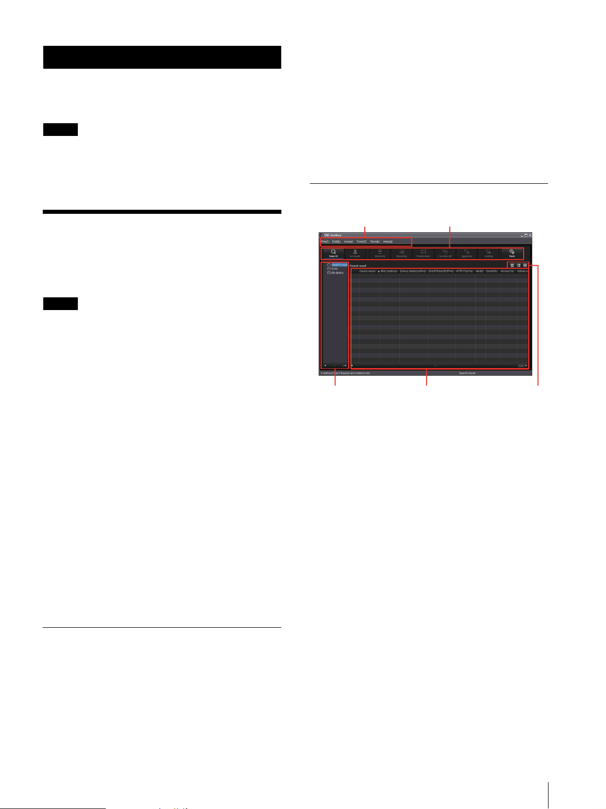
How to use SNC toolbox
Menu bar Function buttons
Device tree display
Device list
Menu bar
All functions can be selected from here.
File (F) menu
Import: Reads the Device list file (CSV format).
Export: Outputs the Device list in a CSV format file.
Close: Exits SNC toolbox.
Edit (E) menu
Cut: Cuts off a device or folder.
Copy: Copies a device or folder.
Paste: Pastes a device or folder.
Select All: Selects all devices in the Device list.
Add Folder: Creates a folder.
Add Device Entry: Manually registers a device.
Modify Device Entry: Edits the device information.
Remove: Removes a device from a folder.
Delete: Deletes a device or folder.
View button
If you are using Windows XP, Windows Vista or
Windows 7, select All Programs from Windows Start
menu, then select SNC toolbox and SNC toolbox in
sequence.
If you are using Windows 8, right-click the mouse on the
Start screen, then select All apps from the application
bar displayed at the bottom of the screen. Select SNC
View (V) menu
Status Bar: Switches show/hide of status at the bottom
of the screen.
Normal: Displays detailed information on a device.
Snapshot small: Displays detailed information on a
device with a small thumbnail.
Using the SNC toolbox
3
Page 4

Snapshot large: Lists devices with large thumbnails.
Column Setting: Displays the setting screen for the
items to display on the list.
Function buttons
Function buttons are used for updating lists and
displaying dialog.
Tools (T) m enu
Search: Searches again for devices.
Enabling the Search external network device(s)
function allows you to search in a wider range.
To configure the function, click Option under Tools,
then select Search Setting in the Network tab.
Device Account: Displays the management screen for
user names and passwords related to the device.
Network Setting: Displays the screen for modifying the
address settings for the selected device.
Device Setting: Displays the settings screen for the
selected device.
Privacy Masking: Displays the Privacy Masking
screen.
Panorama Creator: Displays the Panorama Creator
screen.
Custom Homepage: Displays the Custom Homepage
screen.
Voice alert file:
Create: Displays the Create Voice alert file screen.
Upload: Displays the Uploading Voice alert file
screen.
Firmware Upgrade: Displays the Firmware Upgrade
screen.
CGI Sending: Displays the CGI Sending screen.
Initialize Device:
Reboot: Restarts the device.
Factory default: Initializes the device to factory
default.
Backup setting data: Backs up setting data on a
computer.
Restore setting: Restore the backup setting data to
the device.
Device Homepage: Connects to the device.
Device Log:
System Log: Obtains system log for the device.
Access Log: Obtains access log for the device.
Device Log download: Downloads logs for the device.
Tool Log: Obtains SNC toolbox log.
Option: Displays the screen for modifying SNC toolbox
settings.
Search
Updates the Device list in the search result.
Account
Sets the administrator for each device.
Network
Displays the Network Setting dialog.
Masking
Displays the Privacy Masking dialog.
Panorama
Displays the Panorama Creator dialog.
Upgrade
Updates the device firmware.
Custom HP
Displays the Custom Homepage dialog.
Setting
Displays the settings screen for the device.
Task
Displays the Task List dialog.
Device tree view
This function allows you to customize folders. The
registration details of My device can be displayed in tree
format.
Search result folder
Selecting this folder displays devices in the network
segment that had been searched for when the system is
launched or with the Search function in the device list.
The search result can be displayed for maximum 1,024
cameras.
Task (K) menu
Task Lis t : Displays the Task list screen.
Add Task: Displays the Task Wizard screen.
Modify Task: Displays the Task editing screen.
Delete Task: Deletes task.
Help (H) menu
Tips: Displays tips for the SNC toolbox.
Vers ion : Displays SNC toolbox version information.
4
Using the SNC toolbox
Error folder
When this folder is selected, devices registered in My
device folder that can not be connected are displayed in
the Device list.
Also, if a registered device is not found on the network,
it will also be registered in this folder.
My device folder
When this folder is selected, devices in the Search result
folder or registered manually are displayed in the Device
list.
Page 5

Device list
Devices registered in the folder selected at Device tree
view are displayed in a list.
Device name
Displays individual device names.
Status (Only for Error folder and My device
folder)
You can check the current connection status.
MAC address
You can check the MAC address of the device.
Device address
You can check the IP address of the device.
Port No., HTTP Port No.
You can check the port number of the device.
Searching devices
Clicking Search enables you to detect network devices
connected to the network. In the initial status, it detects
devices on the same network segment. However after
configuring search settings, it is able to search devices
even outside the network segments.
For details on Search settings, see “Setting SNC toolbox
options – Network tab – Search Setting” (page 11).
SNC toolbox automatically searches devices on a
regular basis. You can determine the status of the search
function from the Search button.
Searching
Searches devices on the network on a regular basis and
updates the device list automatically. Click to stop
searching.
DHCP/Fixed IP
Displays whether the IP address of the selected device is
DHCP or fixed IP.
Client certificate
Displays the name of the client certificate used for SSL
function.
Model
Displays the model name.
Serial No.
Displays the serial number.
Version No.
Displays the version of firmware.
Admin name
Displays the administrator user name.
IP Address of NIC (Search result folder only)
Displays the IP address of the NIC (Network Interface
Card) detected.
Tips
• A camera with which SSL communication has been
performed will show on the left side of its IP
address.
• The model on sale in China does not support the SSL
function.
View button
You can change the display format of the Device list
(page 9) .
Stop Searching
Searching stopped. Click to resume searching.
To expand search range
Configure the search settings.
1
Click Option under To ol s.
2
Click the Network tab.
3
Place a check on Search external network
device(s) in Search Setting.
To search in a wider range, set the greater value in TTL.
Tip
If the device is not detected even with the correct search
settings, see “Note” in “Setting SNC toolbox options –
Network tab – Search Setting” (page 11).
Assigning an IP address
To connect the device via network, you need to assign a
new IP address to the device when you install it for the
first time.
Clicking Network after selecting a device to configure
network settings with from the device list, the Network
setting dialog will be displayed. This dialog is
configured with two types of tabs, Basic Setting and
IPv6 Setting.
Using the SNC toolbox
5
Page 6
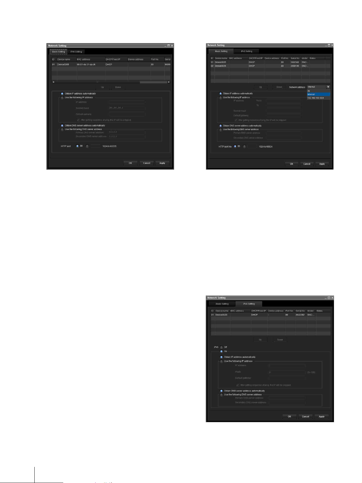
Basic Setting tab (when a single device is
selected from the device list)
Basic Setting tab (when multiple devices are
selected from the device list)
You can configure the network information (IPv4) of the
single device selected in the device list.
Device list: Displays devices for IPv4. After selecting
and setting a device to configure, the device list will
be updated automatically.
Obtain IP address automatically: Sets DHCP mode to
on.
Use the following IP address: Sets the DHCP mode off.
When this is set, specify the IP address, subnet mask,
default gateway to specify the fixed address. You can
also add a check to “After getting response of ping,
the IP will be skipped” to determine whether the
specified IP address is already in use or not.
Obtain DNS server address automatically: Sets DNS
mode to on.
Use the following DNS server address: Sets DNS
mode to off. When this is set, specify the preference
DNS server address and alternative DNS server
address.
HTTP port No.: Normally, 80 should be selected.
When setting a value other than 80, select the textbox
and enter a port number.
You can configure network information (IPv4) for
multiple devices selected in the device list.
Based on the selected multiple devices, the following
points are different from the Basic Setting tab when a
single device is selected.
Use the following IP address: Sets the DHCP mode off,
then specifying the start and end IP addresses
enables you to configure sequential IP addresses.
Network address: Displayed when multiple devices are
selected from the device list and multiple network
addresses exist. Selecting the network address where
the device you want to configure exists enables you
to configure collectively.
IPv6 Setting tab (when a single device is
selected from the device list)
6
Using the SNC toolbox
You can configure the network information (IPv6) of a
single device selected in the device list.
Page 7
Device list: Displays devices for IPv6. After selecting
and setting a device to configure, the device list will
be updated automatically.
IPv6: Enables you to switch IPv6 modes.
Obtain IP address automatically: Sets DHCP mode to
on.
Use the following IP address: Sets DHCP mode to off.
When this is set, specify an IP address, prefix, default
gateway to specify the fixed address. You can also
add a check to “After getting response of ping, the IP
will be skipped” to determine whether the specified
IP address is already in use or not.
Obtain DNS server address automatically: Sets DNS
mode to on.
Use the following DNS server address: Sets DNS
mode to off. When this is set, specify a preference
DNS server address and alternative DNS server
address.
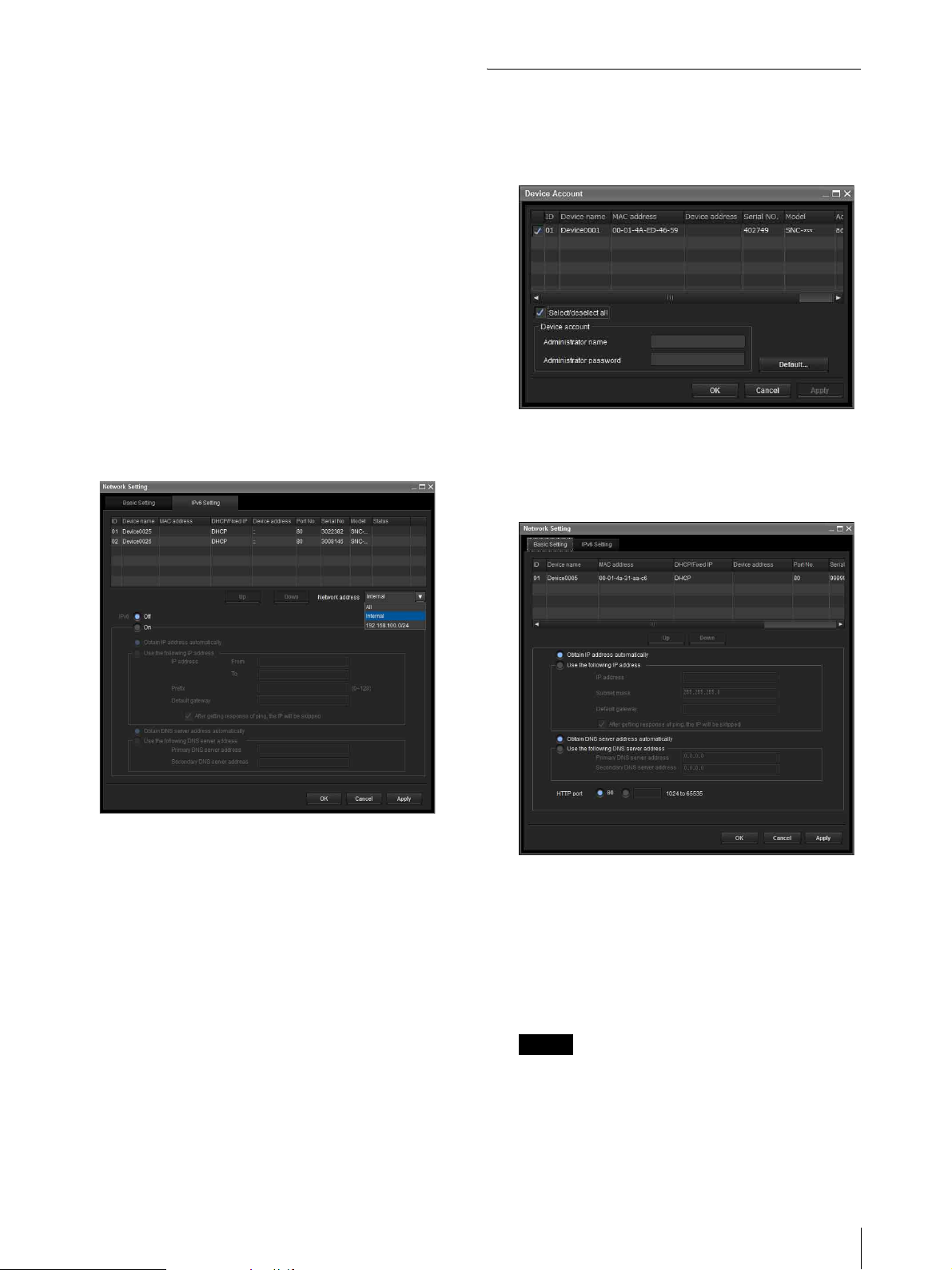
Using the Network settings
1
Select a device you want to assign an IP address to
from the list and click Network.
The account settings screen is displayed.
IPv6 Setting tab (when multiple devices are
selected from a device list)
You can configure network information (IPv6) for
multiple devices selected from the Device list.
Based on the multiple devices selected, the following
points are different from the Basic Setting tab when a
single device is selected.
Use the following IP address: Sets the DHCP mode off,
then specifying the start and end IP addresses
enables you to configure sequential IP addresses.
Network address: Displayed when multiple devices are
selected from a device list and when multiple
network addresses exist. Selecting the network
address where the device you want to configure
exists enables you to configure collectively.
2
Register the name and password of the
administrator and click OK.
The factory settings for both items are “admin”.
The Network Setting screen is displayed.
3
Set the IP address.
To obtain the IP address automatically from a
DHCP server:
Select Obtain IP address automatically.
The IP address, Subnet mask and Default gateway
are assigned automatically.
Note
When you select Obtain IP address
automatically, make sure that the DHCP server is
operating on the network.
Using the SNC toolbox
7
Page 8

To specify the IP address manually:
Select Use the following IP address, and type the
IP address, Subnet mask and Default gateway in the
relevant boxes.
4
Set the DNS server address.
To obtain the DNS server addresses
automatically:
Select Obtain DNS server address automatically.
To specify the DNS server addresses manually:
Select Use the following DNS server address, and
type the Primary DNS server address and
Secondary DNS server address in the relevant
boxes.
5
Set the HTTP port No.
Normally, select 80 for the HTTP port No. To use
another port number, type a port number between
1024 and 65535 in the text box.
Note
Registering in My device
The device tree has three folders by default: Search
result, Error and My device.
The Search result folder and Error folder are fixed, so
you cannot edit the content or rename the folder.
The My device folder can be renamed, and you can add,
delete and move folders.
Search result folder
Displays devices detected by search.
Error folder
Displays devices that are not connected.
My device folder
You can sort and manage devices using any folder.
Adding a folder
1
Select the parent folder to which you want to add a
folder.
When using a port number other than 80, check
with the network administrator first.
6
Confirm that all items are correctly set, then click
OK.
If Setting OK is displayed, the IP address is
correctly assigned.
7
When setting is finished, to access the device
directly, double-click the device name in the list.
The viewer screen of the network device is
displayed on the Web browser.
Note
If the IP address is not set correctly, the viewer does not
appear after step 7. There is a possibility that the device
cannot be searched for. In that case, try to set the IP
address again.
2
Right click the mouse and select Add Folder from
the displayed menu.
A folder is added. Enter a folder name of your
choice.
Registering a device
To register a device, follow the procedure below:
• Registering by Add Device Entry dialog
• Registering by drag & drop
• Registering by copy & paste
Registering by Add Device Entry dialog
1
Select the folder to register the device.
2
Right click the mouse and select Add Device Entry
from the displayed menu.
8
Using the SNC toolbox
Page 9
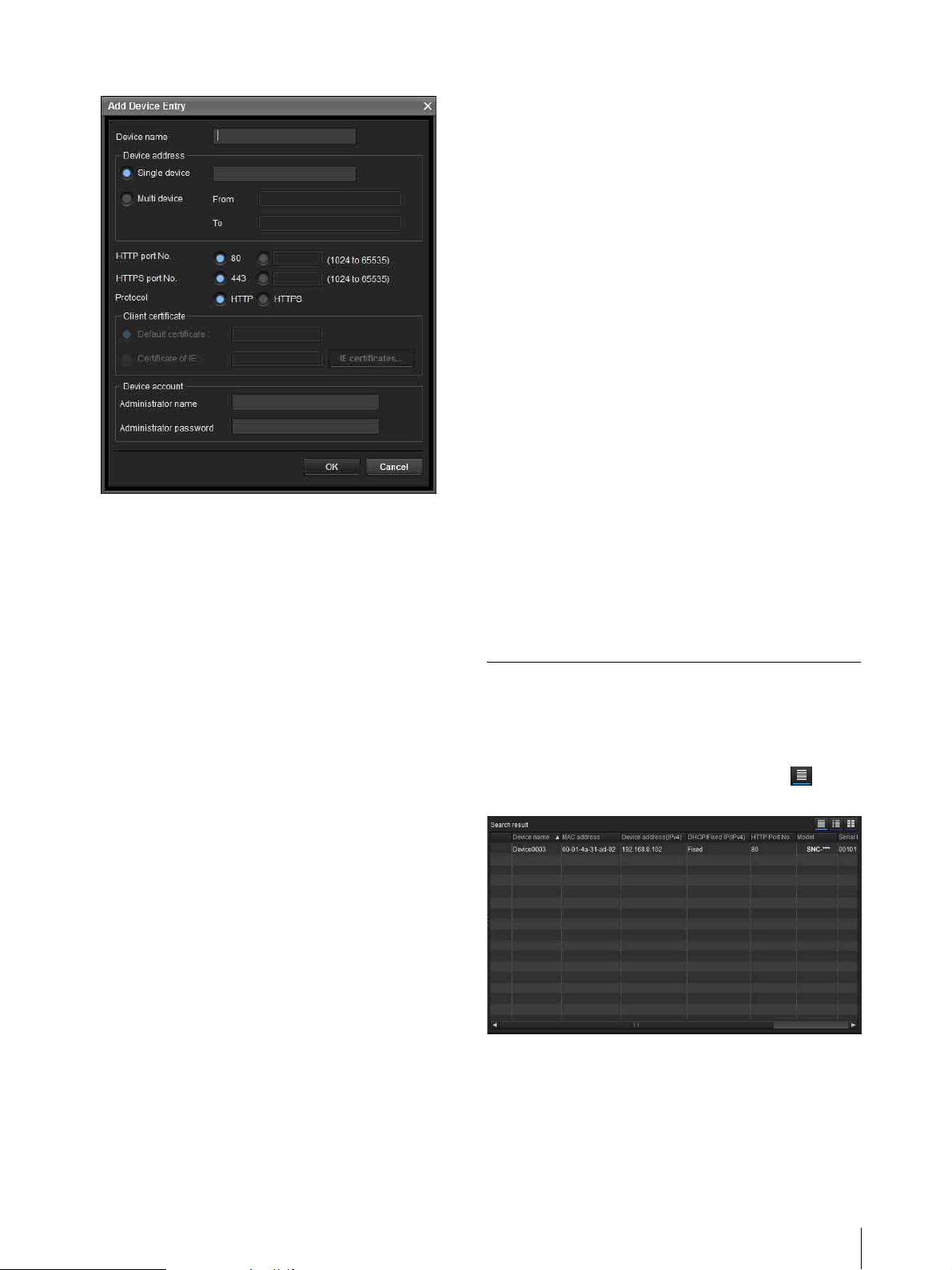
The Add Device Entry dialog appears.
3
Enter the following items:
Device name: Enter a device name of your choice.
Device address: Enter the address of the device to
register. Normally, select Single device. If there is
more than one camera in the specified IP address
range then select Multi device.
HTTP port No.: Normally, 80 should be selected.
When setting a value other than 80, select the
textbox and enter a port number.
HTTPS port No.: Normally select 443. When
setting a value other than 443, select the textbox
and enter a port number.
Protocol: Select communication protocol HTTP
or HTTPS.
Client certificate: Set when using the client
authentication of the SSL function.
Activates when HTTPS is selected.
Default certificate: Select Default client
certificate of the Network tab from Option in
the Tools menu.
Certificate of IE: Press the IE certificates...
button, then select the certificate registered in
the Internet Explorer.
Device account: Enter the user name and password
of the administrator who will access the device in
the Administrator name field and Administrator
password field, respectively.
Registering by copy & paste
Select a device from the Device list in the Search result
folder and right click the mouse. Select Copy from the
displayed menu (or select Copy from the Edit menu).
Next, select the folder to register in and right click the
mouse. Select Paste from the displayed menu.
Renaming the device/folder
Select the folder or device to rename and right click the
mouse. Select Rename from the displayed menu. The
device/folder name is highlighted. Enter the new name.
Deleting a device/folder
Select the device/folder to be deleted from the Device
list or Device tree and right click the mouse. Select
Delete from the displayed menu (or select Delete from
the Edit menu).
Moving a device/folder
You can move a device/folder by following either of the
methods below:
• Select a device/folder from the Device list or Device
tree and drag & drop in the folder to move it to, which
will move the device/folder.
• Select a device/folder from the Device list or Device
tree and right click the mouse. Select Cut from the
displayed menu (or select Cut from the Edit menu).
Next, select the folder to move to and select Paste.
Changing the Device list display method
Details display
Select Normal from the View menu or click to set
to the details display.
4
Click OK to finish registration.
Registering by drag & drop
To add a device, select a device from the Device list in
the Search result folder, and drag & drop to the folder to
register it in.
Using the SNC toolbox
9
Page 10
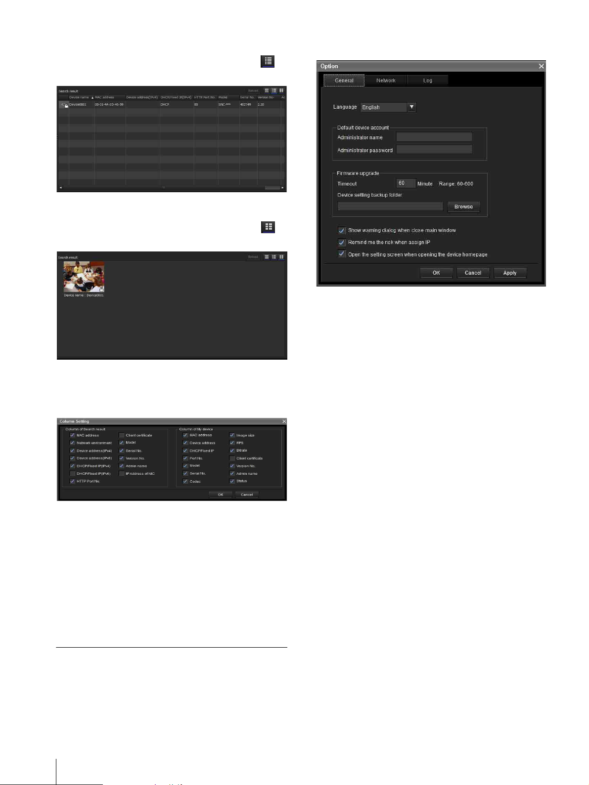
Details display with thumbnails
Select Snapshot(S) from the View menu or click to
set to the details display with thumbnails.
Display with large thumbnails
Select Snapshot(L) from the View menu or click to
set to display with large thumbnails.
General tab
Language
Set language.
Modifying the items to show on list
Select Column setting from the View menu to display
the “Column Setting” dialog.
Check the items you want to display and remove the
checks from items you want to hide.
Click OK after making the changes. The new setting is
reflected on the list and the display returns to the main
screen.
Updating thumbnail images
To display the thumbnail, select the camera of the
thumbnail you wish to update and click Reload to
display the current camera image as the thumbnail.
Default device account
Set the initial values of user name and password for the
administrator accessing the device for each device.
Firmware Upgrade
Make settings related to firmware upgrades.
Timeout: Configure the Timeout of the device when an
upgrade is performed.
Device setting backup folder: Set the backup folder for
the setting file when an upgrade is performed. Click
Browse to display the folder selection dialog and
specify the folder in which to save the file.
Show warning dialog when close main window:
Select to display the warning message.
Remind me the risk when assign IP: Select to display
the warning message.
Open the setting screen when opening the device
homepage: Select to open the setting screen directly.
Setting SNC toolbox options
Select Option from the Tools menu to display the
“Option” dialog. This dialog consists of three tabs:
General, Network and Log.
10
Using the SNC toolbox
Page 11

Network tab
Configure the HTTP proxy and FTP proxy.
When using HTTP proxy, check Use HTTP proxy.
When using FTP proxy, check Use FTP proxy.
To obtain the proxy settings including the automatic
configuration and exceptions from Internet Explorer, set
Acquire Internet Explorer settings to On.
If you are not obtaining the proxy settings from Internet
Explorer, set Acquire Internet Explorer settings to
Off, and enter the proxy address and proxy port number.
SSL Setting
Configure the SSL setting.
Default client cerfificate: Enter the client certificate to
use.
How to process SSL errors in scheduled task or main
window: Select Continue or Cancel.
When SSL function of device is SSL only, allow to
switch from HTTP protocol to HTTPS protocol
automatically: Check this box if necessary.
Notes
• When you have changed the SSL setting, restart the
SNC toolbox.
• The model on sale in China does not support the SSL
function.
• Only the SSL setting registered in My device
activates.
Log tab
IP configuration
Select the IP address used for the Search result folder.
IPv4: Uses IPv4.
IPv6 priority: Uses IPv6. Uses IPv4 if IPv6 is not
selected.
Search Setting
Configures the Search range.
Search external network device(s): Select this option
to search outside the network segment.
TTL: Configures the range to search when Search
external network device(s) is enabled.
Notes
• When the devices outside the network segment are not
found, check the following items:
– check the multicast setting of the router to search the
devices by using multicast
– an IP address of the device to be searched is set
correctly
– if the SSL setting is set on the device, it cannot be
searched as a device outside the network segment.
Disable the SSL setting of the device.
• If Search external network device(s) is enabled, the
network load can be higher as the multicast packet
flows on the network on a regular basis.
Overwrite the oldest log file
To set the size of the log file, check Enable and specify
the minimum required space for a log file.
Log output folder
Click Browse to display the folder selection dialog.
Specify the folder to save the log.
Using Privacy Masking —
Masking a Camera Image
The Privacy Masking function of SNC toolbox allows
you to mask parts of the camera image to be transmitted.
1
Select the camera to set a privacy mask from the
Device list.
Using the SNC toolbox
11
Page 12

2
Click Masking.
PTZ function on:
Using the Privacy Masking
The Privacy Masking screen enables you to set the
privacy mask position.
Click Masking to display the Privacy Masking screen.
Privacy Masking screen
PTZ function off:
Viewer
Viewer
Viewer
A live image of the camera is displayed. You can specify
the position of the privacy mask in this area.
Numbers
The set mask number is displayed in the Viewer.
Frame
Display the frame of the set mask to distinguish the
mask area when the set mask is overlapped.
Panorama area
Display the panorama.
The set privacy mask is displayed by numbers on the
panorama. When the panorama is clicked, the camera
will focus on the place clicked.
Note
If a panorama image has not been created, the default
image is displayed.
PTZ controller
Allows you to pan, tilt and zoom the camera.
12
Using the SNC toolbox
Page 13

Pan/tilt operation
Click the arrows in the direction you want the camera
to move. Press and hold the arrows to move the
camera continuously.
Zoom operation
Click the button to zoom out, click the
button to zoom in. Press and holf the button to zoom
continuously.
The zoom bar displays the current zoom position
with Wide at the right end, and Tele at the left end.
Click the button to adjust the zoom to Wide,
Click the button to adjust the zoom to Te le.
Privacy mask setting section
Allows you to set or delete the privacy mask.
Privacy mask setting range
See User's Guide for the privacy mask setting range.
Using Panorama Creator
— Creating a Panorama Image
The Panorama Creator function of SNC toolbox allows
you to create a panorama image to be displayed on the
main viewer.
Using the panorama image, you can move the camera to
a desired position simply by clicking on the image.
This section explains setup and operation of Panorama
Creator.
Starting the Panorama Creator
Set: Register the area specified on the viewer as a
privacy mask area.
Click Set and the portion of the viewer image is
masked with the privacy mask. The color of the
privacy mask is that selected with the Color dropdown list.
Note
If the mask area is close to the bottom of the image, the
background at the bottom may still be visible.
Clear: Click to delete the privacy mask.
Color
Specify the color or mosaic of privacy masks. This
setting is common to every privacy mask.
Clear All
Click to delete all privacy masks simultaneously.
Setting a privacy mask
To set a privacy mask in a desired position, do the
following:
1
Select the camera to create the panorama image
from the Device list.
2
Click Panorama.
Panorama Creator opens.
Using Panorama Creator
Map View
1
Specify the privacy mask area by dragging the
mouse on the viewer.
2
Select the color or mosaic of the mask from the
Color drop-down list.
Note
The color is common to every privacy mask. The
color last selected is applied.
3
Select the desired privacy mask number in the
privacy mask setting section, and then click Set of
the corresponding number.
The mask is displayed on the viewer.
Arctic View
Viewer
The created panorama image is displayed in the viewer.
This is not available for the camera which cannot swivel
360 degrees.
Pan-Tilt limit
Specify the camera movement area on the panorama
image.
Drag the mouse to draw a rectangle within which the
camera movement is limited. You can enlarge, reduce or
move the created rectangle. To erase the rectangle,
right-click on the mouse or remove the check for pan/tilt
restrictions.
Using the SNC toolbox
13
Page 14

Note
The edges of a panorama image may not be displayed
correctly when the camera is zoomed in.
Make
Starts shooting to create a panorama image (a complete
360-degree panorama image).
Tips
• Panorama images have two formats: Map view and
Arctic view.
• The exposure and white balance settings are fixed
while a panorama image is being created. To create a
clear panorama image, set Exposure to Full auto and
White balance to Auto in the Camera menu and point
the camera at the main subject before starting
shooting.
File open
Allows use of a Bitmap or JPEG image file instead of a
panorama image.
The specified camera movement area will be
effective when the panorama image is saved in the
camera.
3
Click Send to transmit the panorama image to the
camera.
The panorama image is saved in the camera. You can use
the saved panorama image when you control panning
and tilting from the main viewer.
Saving a custom image to the camera
You can save a custom image to the camera in spite of
the panorama image shot by the camera.
Prepare the image to conform to the following
requirements:
• File format: JPEG or Bitmap
• Image size: 320 × 90 pixels (horizontal/vertical)
The camera does not support use of images that do not
conform to the above conditions.
1
Click File open on the Main tab.
The File dialog opens.
Notes
• Only Map view is available.
• The size of the image in the file should be 320 × 90
pixels (horizontal/vertical). Other image sizes are not
supported.
Save
You can save the panorama image in a file.
Note
Only Map view panorama images can be saved.
Send
Transmits a panorama image converted into a JPEG file
to the camera.
Both Map view and Arctic view panorama images are
sent to the camera.
Creating and transmitting a panorama
image
1
Click Make on the Main tab to start shooting.
A panorama image will be created.
Note
Do not perform settings of the camera or move the
camera during shooting.
2
Select the image you have prepared.
3
Specify the camera movement area by dragging the
mouse to draw a rectangle on the panorama image.
The specified camera movement area will be
effective when the panorama image is saved in the
camera.
4
Click Send to transmit the prepared image to the
camera.
The image is saved in the camera. You can use the saved
image when you control panning and tilting from the
main viewer.
Tip
The panorama image is the still image converted from
the image taken when you were going to create a
panorama image with Panorama Creator. When the
camera is moved or when the layout around the camera
is changed, create the panorama image again.
Using the Custom Homepage —
Setting the customized homepage
The Custom Homepage function of the SNC toolbox
allows you to store the homepage that you have created
in the camera and watch it.
2
14
Using the SNC toolbox
Specify the camera movement area by dragging the
mouse to draw a rectangle on the Map view
panorama image.
Notes on creating the homepage
When you are creating the homepage, note the following
points.
Page 15

• The file name should be typed using up to 24
characters including the extension.
• The file size of the homepage should be 2.0 MB or
less.
• To see the created homepage, set the Homepage in the
Layout tab from viewer menu.
Uploading the homepage to the camera
using the Custom Homepage
1
Select the device to upload from the Device list.
You can select multiple devices at the same time.
2
Click the Custom Homepage.
The “Custom Homepage” dialog opens.
Read the notes carefully.
Note
Depending on the proxy server, communication
with the camera may not be performed correctly. In
that case, connect the camera to the same network
segment, etc. and execute the Custom Homepage
without using a proxy server.
Using Create Voice alert file
From the Tool s menu, select Create Voice alert file and
Create in this order.
The SNC toolbox contains a sample of a Voice alert file.
To create new a Voice alert file, use this function.
Note
Use this function by inputting the sound to be recorded
from the microphone input of your computer.
(save) / (stop)
Clicking starts recording sound via the
computer’s microphone. The maximum recording time
is 30 seconds.
The codec specified in “Codec during recording” is used
for recording.
3
Type the path in which your homepage is stored.
4
Click Start uploading.
Uploading of the homepage file to the camera
starts.
5
Click Cancel to exit the program.
Creating and Uploading the Voice alert file
The Voice alert file function allows you to create a Voice
alert file and upload the Voice alert file to a device.
To stop recording, click . Recording will stop
automatically in 30 seconds.
When recording is completed, the recorded Voice alert
file will be saved to the computer.
Note
Use a file name that is 33 characters or less.
(Codec during recording)
Select the codec during recording from the following.
Audio codec Transmission rate
G.711(µ-LAW) 64kbps
G.726 40kbps
G.726 32kbps
G.726 24kbps
G.726 16kbps
AAC 128kbps
AAC 64kbps
(playback) / (stop)
Clicking starts playback.
To stop playback, click .
Using the SNC toolbox
15
Page 16

(Voice alert file display)
Displays the name of the saved Voice alert file.
/
(recording/playback progress bar)
You can check recording or playback progress with this
bar.
During recording, the remaining recording time is
displayed on the upper right of the bar.
During playback, the current playback time/the Voice
alert file length are displayed in seconds on the upper
right of the bar.
Canceling
Close the Create Voice alert file screen.
2
Right-click the mouse and select Voice alert file
and Upload in this order from the displayed menu.
The Uploading Voice alert file screen will be
displayed.
Creating the Voice alert file
1 Click to record a Voice alert file.
2 Click to stop recording the Voice alert file.
Alternatively, recording stops automatically after 30
seconds.
When recording is completed, the recorded Voice
alert file will be saved to the computer.
Checking the Voice alert file
1 Click to start the playback of the recorded
Voice alert file.
You can check the Voice alert file.
2 Click to stop the playback of the Voice alert
file.
Alternatively, the playback stops automatically after
the Voice alert file has completed playing.
Using Uploading Voice alert file
1
From the Device list, select a device to upload a
Voice alert file.
You can select multiple devices at the same time.
Device list
Tip
The Uploading Voice alert file screen can also be
displayed using the following method:
•From the Too ls menu, select Voice alert file and
Upload in this order.
Device List
Devices to be used for the Uploading Voice alert file are
displayed in a list.
During uploading, the progress bar is displayed.
Status 1, Status 2, Status 3
Displays the current status as shown below.
Blank: This is the default status.
Not supported: The Voice alert file is not supported
by the device.
Uploading: The Voice alert file is being uploaded.
OK: The Voice alert file uploaded successfully.
Failed: Uploading of the Voice alert file failed.
Cancel: Uploading of the Voice alert file is canceled.
The current status is displayed by file number.
Display sample:
16
Using the SNC toolbox
File1, File2, File3
Voice alert file names currently uploaded in the
device are displayed. If the device does not support
File2 and File3, <No match> is displayed.
Page 17

Up/Down: Selects the order of devices to be
uploaded.
Test play
Displays the Test play screen to test play.
File
Displays the selected file names.
Clear
Clears the selected Voice alert file.
Select
Displays the Select Voice alert file screen to select a
Voice alert file to be uploaded.
Start uploading
Starts uploading a Voice alert file. When uploading
starts, it changes to Stop uploading.
(playback progress bar)
You can check the playback progress with this bar.
On the upper right of the bar, the current playback time/
the Voice alert file length are displayed in seconds.
OK
Selects the read Voice alert file and closes the Select
Voice alert file screen.
Cancel
Closes the Select Voice alert file screen with no Voice
alert file selected.
Reading the Voice alert file
Click Browse to select a Voice alert file saved in your
computer. The selected file name is displayed in the text
box.
Cancel
Exit Uploading Voice alert file.
Note
When uploading of a Voice alert file fails, select “Tool
Log” from the Tool s menu to check the log.
Select Voice alert file
Allows you to start the playback to select or check a
Voice alert file to be uploaded.
Click Select.
The Select Voice alert file screen is displayed.
Browse
Reads the Voice alert file saved in the computer.
(playback) / (stop)
After reading a Voice alert file, click to start the
playback. To stop the playback, click .
(Voice alert file display)
Displays the name of the read Voice alert file.
(Voice alert file codec display)
Displays the codec of the read Voice alert file.
Checking the Voice alert file
1 Click to start the playback of the selected
Voice alert file.
You can check the Voice alert file.
2 Click to stop the playback of the Voice alert
file.
Alternatively, the playback stops automatically after
the Voice alert file has completed playing.
Selecting the Voice alert file
Click OK to select the read Voice alert file.
Click Cancel to close the Select Voice alert file screen
with no Voice alert file selected.
Uploading the Voice alert file
Uploads a Voice alert file to the device.
Uploading the Voice alert file
Click Start uploading to upload all the selected Voice
alert files to the device.
Notes
• To stop uploading, click Stop uploading. However,
devices that begin uploading a file cannot be canceled
until the file has completed uploading.
• The uploaded Voice alert file will be overwritten. If no
file is selected, the file corresponding to the device
number will not be deleted by clicking Start
uploading.
• When uploading of a Voice alert file fails, select “Tool
Log” from the Tool s menu to check the log.
Using the SNC toolbox
17
Page 18

Test playing/Deleting the Uploaded Voice
alert file
Allows you to test play or delete an uploaded Voice alert
file.
Select a device from Device list, and click Test p l a y.
The Test play screen is displayed.
(uploaded Voice
alert file display)
Displays the name of the uploaded Voice alert file.
2
Right click the mouse. Click Firmware Upgrade
from the displayed menu.
The Firmware Upgrade screen is displayed.
(Test play)
Starts the test play of the uploaded Voice alert file on the
device.
Delete
Deletes the uploaded Voice alert file.
Notes
• When multiple devices are selected from the Device
list, the Test play function cannot be used.
• To test play, check if the audio output of the device is
connected to the speaker.
Starting the Test play
Click to start the test play of the Voice alert file
uploaded in the device once.
Deleting the Voice alert file
To delete the Voice alert file uploaded in the device,
click Delete.
Using the Firmware Upgrade
Device list Module list
Tip
The Firmware Upgrade screen can also be displayed
using the following method:
• Select Firmware Upgrade from the Tools menu.
Device list
Select the device to upgrade.
A progress bar is displayed when upgrading is in
process.
The status field shows current status.
Module list
To display the dialog, click the Browse button to the
right of the model (in the module list) to upgrade. Select
the target SVU file from the dialog.
You can select one file for each model.
Upgrading
1
Set the order to perform device upgrading using Up
and Down.
The Firmware Upgrade function of the SNC toolbox
allows you to upgrade the firmware of the device.
Starting the Firmware Upgrade
1
Select the device to upgrade its firmware from the
Device list.
You can select multiple devices at the same time.
18
Using the SNC toolbox
2
Click Browse and select an upgrade file for each
model.
3
Select how many devices to upgrade in Paralleled
upgrade quantity.
4
To back up the device setting, check Backup
device setting.
Page 19

Tip
You can specify the backup folder under Device setting
backup folder, on the General tab in Option from the
Tools menu.
5
When sending is completed, click Save all
responses. Response content of all devices in the
list, to which a CGI command is sent, will be saved
in CSV format.
5
Click Start upgrading.
Upgrading starts.
Notes
• To stop upgrading, click Stop upgrading.
To protect the device, once some devices start
upgrading, they cannot be canceled until the
upgrading is completed.
• Do not turn off the power until the device restarts after
upgrading.
Using CGI Sending
The CGI Sending function allows you to send CGI to a
device.
How to perform CGI Sending
1
From the Device list, select the camera to receive
CGI.
2
Right click the mouse. Click CGI Sending from
the displayed menu.
The CGI Sending screen is displayed.
Using the Schedule Task
You can specify the time or interval to change the Device
setting or perform Firmware upgrade.
Click Ta sk to display the Task List, which shows a list
of scheduled executable tasks.
Task List
Displays the list of scheduled executable tasks.
Add
Displays the Task Wizard.
Modify
You can edit a task.
3
Enter a command in the CGI command box.
4
Click Send.
The CGI command is sent to the selected camera(s)
in order of ID.
Delete
You can delete a task.
Show Detail
Displays the detailed information on a task.
Start
This reserves a task.
Stop
You can cancel a task reservation.
Cancel
Closes the Task List.
Creating a task
1
Click Add.
Using the SNC toolbox
19
Page 20

Displays Task Wizard.
2
Click Next.
3
Select a device to which the task is assigned.
A list of devices registered in My device is
displayed. Select the device you want to assign the
task to from the My device list, and register in
Device(s) in task list.
Select Device Setting or Firmware Upgrade.
6
Click Next.
For Device Setting:
Edit the value for the setting you wish to change.
See “Configuring the device setting” on page 21.
for changing the values.
Click Next to display the confirmation screen for
setting change. Check to see if the setting is correct.
If correction is needed, click Back to return to the
previous screen to redo the setting.
My Device: Display a list of cameras registered in
My devices.
Device(s) in task: Display a list of devices set to
execute a task.
Add: Register a device in Device(s) in task.
Remove: Removes a device from Device(s) in task.
Up/Down: Changes the order of devices in
Device(s) in task.
4
Click Next.
5
Select the task action.
For Firmware Upgrade:
Set the firmware for the device you want to
upgrade.
See “Using the Firmware Upgrade” on page 18 for
setting firmware.
7
Click Next.
8
Set the schedule.
Task name
Name the task.
20
Using the SNC toolbox
Recurrence pattern
Specify the operation interval.
One time: Runs the task once.
Hourly: Specify the operation frequency in units of
hours. (Possible set value: 1 to 99)
Page 21

Daily: Specify the operation frequency in units of
days. (Possible set value: 1 to 99)
Weekly: Specify the operation frequency in units
of weeks and days of the week. (Possible set value:
1 to 99)
Range of recurrence
Specify the starting date and time, and the end date
and time.
Start: Set the starting date.
Execution time: Set the starting time.
No end date: This setting does not set an end date.
End after: Specify the number of times to execute
the operation.
End by: Set the end date.
Select a subcategory to display setting items on the right
side of the screen.
Item
Displays the setting items. Select a line to change its
value.
Value
Displays the value of an item. Select or enter a value to
change the value.
Explanation
Displays the range of value for setting and
supplementary explanations.
9
Click Next.
Check the setting when the final confirmation
screen for task setting is displayed.
If correction is needed, click Back to return to the
previous screen to redo the setting.
10
Click Finish.
Configuring the device setting
You can configure advanced settings for a device on the
Device Setting screen.
When you select a device(s) on the Device list and select
Device Setting from the Too ls menu, or when you right
click on the device selection screen and click Device
Setting in the displayed menu, the Device Setting screen
is displayed.
Display sample:
Setting tree Item Value
OK
Apply the setting and close the Device Setting screen.
The main screen of SNC Toolbox is displayed.
Cancel
Close the Device Setting screen without changing the
setting. The main screen of SNC Toolbox is displayed.
Apply
Apply the setting.
Other settings
See User's Guide for configuring the settings.
Device restart and initialization
You can restart and initialize (restore factory default) a
selected device. Multiple devices can be selected
simulteneously for restart and initialization.
Restarting a device
Click Tools, Initialize Device and Reboot in this order
on the menu bar to restart the device.
Explanation
Setting tree
All settings are sorted into categories. Click + to display
the subcategories under a category. Click – to hide the
subcategories.
Initializing a device
Click To ol s, Initialize Device and Factory Default in
this order on the menu bar to initialize the device
(restore factory default).
Installing SNC toolbox
1
Download the installer of SNC toolbox from the
appropriate folder of the following website.
http://www.sony.net/ipela/snc
2
Extract the downloaded installer ZIP file.
3
Run the “SncToolbox_Setup.exe” file.
Using the SNC toolbox
21
Page 22

4
Install the SNC toolbox following the wizard
displayed.
If the Software License Agreement is displayed,
read it carefully and accept the agreement to
continue with the installation.
Tip
You should be logged in as administrator to install
the software.
Using the SNC audio upload tool
The SNC audio upload tool allows you to transmit sound
from the computer to the camera.
This section explains the setup and operations of the
SNC audio upload tool.
5
Click Finish. The installation is completed.
The SNC audio upload tool supports the following audio
data to be transmitted.
Audio CODEC Transmission rate
G.711 (µ-LAW) 64 kbps
G.726 40 kbps
G.726 32 kbps
G.726 24 kbps
G.726 16 kbps
AAC 128 kbps
AAC 64 kbps
Notes
• Only one user can transmit sound to the camera.
Meanwhile, another user will not be able to transmit
sound to the camera.
• If proxy server is enabled, sound uploading to the
camera may fail. In that case, disable the proxy server.
• SNC audio upload tool may not operate correctly if
personal firewall software or antivirus software is used
in your computer. In this case, disable the
corresponding software.
• If you are using Windows XP Service Pack 2 or later,
Windows Vista, Windows 7 or Windows 8, disable
Windows Firewall. Otherwise SNC audio upload tool
will not operate correctly. To set Windows Firewall
see: “Configuring Windows Firewall” in “When using
Windows Vista” on page 27, or “Configuring
Windows Firewall” in “When using Windows 7” on
page 28, or “Configuring Windows Firewall” in
“When using Windows 8” on page 30.
22
Using the SNC audio upload tool
Installing SNC audio upload tool
Install the SNC audio upload tool following the wizard
displayed.
If the Software License Agreement is displayed, read it
carefully and accept the agreement to continue with the
installation.
Page 23

Connecting the Camera to the Computer
1
Connect a speaker to the 5 (line output) jack on the
camera.
2
Connect a microphone to the microphone input jack
on the computer.
Note
If the microphone input jack of the computer is not set
correctly, no sound is transmitted from the computer and
nothing is output from the speaker connected to the
camera.
Set the microphone input jack from the control panel of
Windows.
On Windows XP
1 Select Sounds and Audio Device from Control
Panel.
2 Click Vo l um e in the Sound Recording section on
the Audio tab.
The Recording Control window opens.
3 Check Select in the Microphone section.
On Windows Vista, Windows 7, Windows
8
There are no settings regarding the microphone jack.
If recording cannot be made, connect a microphone
device to the computer and check that the recording
device operates correctly, as follows:
1 Select Sound from Control Panel.
2 Open the Recording tab and check that Windows has
recognized the hardware correctly.
Setting tab
Use this menu to set the camera to transmit audio from
a computer or upload an audio file.
User
Set the UserID and Password for the administrator.
Single sign-on: Select On to use the same user ID and
same password for all the cameras. Select Off to set
the user ID and password individually for each
camera.
For details on setting with Off, see “UserID/
Password” on page 24.
UserID: This item can be set when Single sign-on is set
to On. The user ID specified here is applicable to all
cameras.
Password: This item can be set when Single sign-on is
set to On. The administrator password specified here
is applicable to all cameras.
How to use the SNC audio upload tool
When you start the SNC audio upload tool, the Setting
tab is displayed.
Proxy
Check this box when you use a proxy server for
communications. When it is not checked, direct
communication with the camera is performed.
Auto detect: Select On to obtain the proxy setting
automatically from Internet Explorer.
Proxy address: Type the IP address or host name of the
proxy server.
Proxy port: Type the port number used for
communication with the proxy server.
Note
The Proxy setting is applicable to all cameras. You
cannot use individual proxy settings for each camera.
Using the SNC audio upload tool
23
Page 24

Codec
Select the audio mode (Codec) from the drop-down list.
Save camera setting
Check this box to store the current settings and camera
list in the Setting tab. The same settings will be recalled
when the camera is rebooted.
Click this button repeatedly to hide/show the camera list.
Target camera(s) (Camera list)
When the application is launched, it displays Sony
network cameras on the same network segment in the
camera list automatically. Up to 256 cameras can be
displayed in the list.
Select the check box on the left of the row to enable
audio transmission and audio file uploading for that
camera. You can then enable these functions
simultaneously for multiple cameras.
Type the user ID and password for the administrator and
click OK.
Note
If you select multiple cameras from the camera list, the
same user ID and password are set for all those selected
cameras.
Notes
• Camera(s) connected to the same network segment
after launching the application will not be displayed.
• The SNC audio upload tool cannot detect network
cameras that are not equipped with audio.
Camera select checkbox: The check box is located on
the left end of the row. Select this check box to
enable audio transmission and audio file uploading
for that network camera.
MAC address: Displays the MAC address of the
network camera.
IP address: Displays the IP address of the network
camera. “DHCP” is shown at the end of the IP
address when the IP address is obtained with a
DHCP server.
Model: Displays the model name of the network
camera.
Serial: Displays the serial number of the network
camera.
User: Displays the specified user ID and password. The
password is shown as turned letters.
Select all
Click to select all the cameras in the camera list. This is
useful, for example, when you delete all the cameras
from the list or specify the same user ID and password
for all cameras.
UserID/Password
Use this item when you specify the user ID and
password to communicate with selected camera(s) only.
Select camera(s) from the camera list and click this
button. The following dialog opens.
Add
Use this item when you add a new network camera to the
camera list manually. Click this button to open the
following dialog.
Type the IP address and port number of the camera to be
added and click OK.
Notes
• An error dialog appears if the specified IP address in
the camera list is assigned for a device other than the
network camera, or does not exist in the network.
• You cannot add new cameras if the maximum of 256
cameras has been reached.
Delete
Click this button to delete the selected camera(s) from
the camera list.
Note on switching the tab
If an error occurs when you switch from the Setting tab
to the Audio upload tab or the Voice alert tab, the camera
is shown in red. In this case, check the camera settings
and the user ID and password settings.
24
Using the SNC audio upload tool
Page 25

Audio upload tab
Use this menu to transmit audio from the computer to
the camera. You can transmit audio to multiple cameras
displayed in the camera list simultaneously.
Before transmitting, set Audio upload to Enable on the
Common tab of the Camera menu.
Target camera(s) (Camera list)
Displays the cameras selected with the camera select
checkbox of the camera list in the Setting tab.
The list shows the information and status of the selected
cameras.
IP address: Displays the IP address of the network
camera. “DHCP” is shown at the end of the IP
address when the IP address is obtained with a
DHCP server.
Tips
• During SSL communication, appears on the left
side of the IP address of the camera.
• The model on sale in China does not support the SSL
function.
Model: Displays the model name of the network
camera.
Serial: Displays the serial number of the network
camera.
Status: Displays the current status of the camera.
Ready: The camera is ready for connection.
Connected: Camera connection was successful.
Fault: Camera connection failed.
Sending: Audio data is being transmitted.
(start) / (stop)
Click (start) to start audio transmission. The
transmission speed is displayed in the Bitrate box during
transmission. You can adjust the microphone volume
and enable/disable muting, if necessary.
To stop audio transmission, click (stop).
Notes
• Audio transmission stops if you switch the tab during
transmission.
• Audio may be interrupted when the IP address is
changed if Obtain an IP address automatically
(DHCP) is set on IP address in the Network menu.
• Audio may be interrupted if you transmit it to many
cameras simultaneously.
Sound adjustment and indicators
Adjust the microphone input volume by moving the
slider bar. You can adjust the volume even
during transmission.
Click to enable/disable sound muting. The
microphone input volume level is displayed.
The transmission rate is displayed in the Bitrate box.
Voice alert tab
Use this menu to record sound via a microphone
connected to the computer, and upload the recorded
audio file to the camera. You can upload the audio file to
multiple cameras selected from the camera list
simultaneously.
Click this button to hide the camera list. Click it again to
display the camera list.
Using the SNC audio upload tool
25
Page 26

(playback)
To start playback, open the recorded file or another
audio file and click this icon.
You can check the recorded sound or the contents of the
selected audio file. During playback, the progress bar
shows playback progress.
(stop)
Click to stop recording or playback.
When you click it during recording, recording stops, and
you can review the recorded sound or upload the
recording to the camera.
When you click it during playback, playback stops and
the progress bar returns to the start position.
(recording)
Click to start recording of sound via the computer’s
microphone. Maximum recording time is 30 seconds.
The codec specified in the Setting tab is used for the
recording.
The recorded file is displayed as “RecordedFile.vof”.
Notes
• Recording or playback stops if you switch the tab
during recording or playback.
• The recorded file is not stored in the computer.
Recording/playback progress bar
Specify the voice alert number to which you want to
upload an audio file. For example, select 1 when
uploading to voice alert 1.
The name of the uploaded audio file is displayed to the
right of the number.
“Not uploaded” is displayed if no audio file is uploaded
to the camera.
The audio file name will be “RecordedFile” + “Voice
alert number” + “.vof” if you upload an audio file
recorded using and not stored in the computer.
Note
The audio file name for the camera selected in the
camera list is displayed here. To check the uploaded file
name, click on the camera in the camera list.
(upload)
Click to upload the recorded or selected audio file to the
camera specified in the Setting tab. Only one audio file
can be uploaded to the camera at a time.
Note
Uploading a new audio file overwrites the audio file
previously uploaded to the camera.
Click this button to hide the camera list. Click it again to
display the camera list.
You can check recording or playback progress with this
bar.
During recording, the far right of the bar represents
30 seconds, and the remaining recording time is
numerically displayed below the bar.
During playback, the length of the bar depends on the
recorded time.
(file open)
Click to select a previously saved audio file. You can
play the selected audio file or upload it to the camera.
(save)
Click to save a recorded audio file to the computer.
Voice alert number select
Target camera(s) (Camera list)
Displays the cameras selected with the camera select
checkbox of the camera list in the Setting tab.
The list shows information and status of selected
cameras.
IP address: Displays the IP address of a network
camera. “DHCP” is shown at the end of the IP
address when the IP address is obtained from a
DHCP server.
Tips
• During SSL communication, appears on the left
side of the IP address of the camera.
• The model on sale in China does not support the SSL
function.
Model: Displays the model name of the network
camera.
Serial: Displays the serial number of the network
camera.
Progress: Displays the progress of audio file
transmission.
Status: Displays the current status of the camera.
Ready: The camera is ready for connection.
Inquiry: Camera information is being requested.
26
Using the SNC audio upload tool
Page 27

No func: The camera does not support the Voice
alert function.
Uploading: An audio file is being uploaded.
Fault: Audio file uploading failed.
No Privilege: The camera is not authorized to
upload audio files.
Succeeded: The audio file uploaded successfully.
Configuring Windows Firewall
When using Windows Vista
Uploading a recorded audio file to the
camera
Tip
Before operating, create an audio file and set the camera
to upload using the Setting tab.
1
Click (recording) in the Voice alert tab to
start recording.
2
Click (stop) to stop recording.
Recording will stop automatically in 30 seconds.
3
Select the voice alert number.
4
Click (upload) to transmit the audio file to the
camera.
Saving the recorded audio file to the
computer
1
Click (recording) in the Voice alert tab to
start recording.
Configuring Windows Firewall
SNC toolbox or SNC audio upload tool may not operate
correctly depending on the configuration of Windows
Firewall. (No cameras are shown in the list even if they
are detected.) In this case, confirm the Windows
Firewall configuration as follows:
1
Select Control Panel from the Start menu of
Windows.
2
Click Windows Firewall.
3
Select Turn Windows Firewall on or off.
“User Account Control – Windows needs your
permission to continue” may appear. In this case,
click Continue.
4
Select Off in the General tab.
2
Click (stop) to stop recording.
Recording will stop automatically in 30 seconds.
3
Click (save).
The Save as dialog appears. Type the file name and
save it.
Uploading the saved audio file to the
camera
1
Click (file open) in the Voice alert tab and
select the audio file to be uploaded.
2
Select the voice alert number.
3
Click (upload) to transmit the audio file to the
camera.
The cameras will be displayed in the list.
If you want to keep Windows Firewall On, continue
with the following steps.
5
Select the Exceptions tab.
6
Click Add Program….
Configuring Windows Firewall
27
Page 28

7
If the Add Program dialog appears, select SNC
toolbox or SNC audio upload tool and click OK.
SNC toolbox or SNC audio upload tool is added to
the Program or port list.
8
Click OK.
When using Windows 7
Configuring Windows Firewall
SNC toolbox or SNC audio upload tool may not operate
correctly depending on the configuration of Windows
Firewall. (No cameras are shown in the list even if they
are detected.) In this case, confirm the Windows
Firewall configuration as follows:
To turn Windows Firewall off
1
Select Control Panel from the Start menu of
Windows.
2
Click Windows Firewall.
3
Select Turn Windows Firewall on or off.
When the settings above are completed, cameras on
the network will be displayed on the SNC toolbox
or SNC audio upload tool.
4
Select Turn off Windows Firewall.
The cameras will be displayed in the list.
28
Configuring Windows Firewall
Page 29

To turn Windows Firewall on
1
Select Control Panel from the Start menu of
Windows.
2
Click Windows Firewall.
3
Select Allow a program or feature through
Windows Firewall.
4
Select Allow another program....
5
Add program.
When the above procedure is completed, the
cameras connected in the local network are
displayed in SNC toolbox or SNC audio upload
tool.
Configuring Windows Firewall
29
Page 30

When using Windows 8
Configuring Windows Firewall
SNC toolbox or SNC audio upload tool may not operate
correctly depending on the configuration of Windows
Firewall. (No cameras are shown in the list even if they
are detected.) In this case, confirm the Windows
Firewall configuration as follows:
To turn Windows Firewall off
1
Press the Windows key + X, then select Control
Panel from the displayed list.
2
Click Windows Firewall.
3
Select Turn Windows Firewall on or off.
To turn Windows Firewall on
1
Press the Windows key + X, then select Control
Panel from the displayed list.
2
Click Windows Firewall.
3
Select Allow an app or feature through Windows
Firewall.
4
Select Turn off Windows Firewall.
4
Select Allow another app....
The cameras will be displayed in the list.
30
Configuring Windows Firewall
Page 31

5
Add an app.
When the above procedure is completed, the
cameras connected in the local network are
displayed in SNC toolbox or SNC audio upload
tool.
Configuring Windows Firewall
31
Page 32

Sony Corporation
 Loading...