

Page 1

Hybrid Camera
4-412-923-12 (1)
Receiver
User’s Guide
Software Version 1.1 or later
Before operating the unit, please read this manual thoroughly
and retain it for future reference.
SNCA-ZX104
© 2012 Sony Corporation
Page 2

Table of Contents
Overview
Features .................................................................. 3
How to Use This User’s Guide .............................. 4
System Requirements ............................................ 4
Preparation
Assigning the IP Address to the Unit ................... 5
Assigning an IP address using SNC toolbox ..... 5
When using Windows XP Service Pack 2 or
later ................................................................... 7
When using Windows Vista ............................... 8
When using Windows 7 ................................... 11
Accessing the System Using the Web
Browser ................................................................. 13
Administrating the unit
Basic Operations of the Setup Menu ................. 15
Logging in ........................................................ 15
Language .......................................................... 16
Configuration of the Administrator menu ........ 16
Displaying System Information
— System Menu ................................................... 16
System Tab ....................................................... 16
Initialize Tab ..................................................... 16
Configuring Serial PTZ Operations
— Serial Menu ..................................................... 17
Configuring the Network — Network Menu .... 18
Setting the SSL function — SSL Menu ............. 19
Setting tab ........................................................ 19
Setting the User — User Menu ........................... 21
Others
Using the SNC toolbox ........................................ 22
Starting SNC toolbox ....................................... 22
How to use SNC toolbox .................................. 22
Registering in My device ................................. 23
Changing the Device list display method ......... 25
Setting SNC toolbox options ............................ 25
Using the Firmware Upgrade ........................... 26
Glossary ................................................................ 27
Index ..................................................................... 29
2
Table of Contents
Page 3

Overview
Features
NOTICE TO USERS
© 2012 Sony Corporation. All rights reserved. This
manual or the software described herein, in whole or in
part, may not be reproduced, translated or reduced to
any machine readable form without prior written
approval from Sony Corporation.
Overview
• SNCA-ZX104 is an IPELA HYBRID-compatible
hybrid camera receiver.
• The IPELA HYBRID-compatible camera connected
to this unit’s SLOC port connects to an external
network via this unit’s LAN port. Also, composite
video signals via from a camera are output via this
unit’s video output terminal.
• Up to 4 IPELA HYBRID-compatible cameras can be
connected to this unit.
• An IPELA HYBRID-compatible camera’s pan, tilt
and zoom, etc., functions can be controlled from a
keyboard connected to this unit.
• The Serial PTZ function converts control signals input
from the RS-485 port to TCP/IP packets and sends
them via a network. Connect a keyboard compatible
with the Pelco-D protocol to the RS-485 port.
• You can control up to 255 Serial PTZ-compatible
cameras registered to a single SNCA-ZX104.
SONY CORPORATION PROVIDES NO
WARRANTY WITH REGARD TO THIS MANUAL,
THE SOFTWARE OR OTHER INFORMATION
CONTAINED HEREIN AND HEREBY EXPRESSLY
DISCLAIMS ANY IMPLIED WARRANTIES OF
MERCHANTABILITY OR FITNESS FOR ANY
PARTICULAR PURPOSE WITH REGARD TO THIS
MANUAL, THE SOFTWARE OR SUCH OTHER
INFORMATION. IN NO EVENT SHALL SONY
CORPORATION BE LIABLE FOR ANY
INCIDENTAL, CONSEQUENTIAL OR SPECIAL
DAMAGES, WHETHER BASED ON TORT,
CONTRACT, OR OTHERWISE, ARISING OUT OF
OR IN CONNECTION WITH THIS MANUAL, THE
SOFTWARE OR OTHER INFORMATION
CONTAINED HEREIN OR THE USE THEREOF.
Sony Corporation reserves the right to make any
modification to this manual or the information
contained herein at any time without notice.
The software described herein may also be governed by
the terms of a separate user license agreement.
• “IPELA” and are trademarks of
Sony Corporation.
• IPELA HYBRID” and are
trademarks of Sony Corporation.
• Microsoft, Windows and Internet Explorer are
registered trademarks of Microsoft Corporation in
the United States and/or other countries.
• sloc™ is a trademark owned by the Intersil
Corporation family of companies.
• Adobe, Adobe Reader and Adobe Flash are
trademarks of Adobe Systems Incorporated in the
United States and/or other countries.
All other company and product names are trademarks
or registered trademarks of the respective companies or
their respective makers.
Features
3
Page 4

How to Use This User’s
System Requirements
Overview
Guide
This User's Guide explains how to operate this unit from
a computer.
The User’s Guide is designed to be read on the computer
display.
This section gives tips on making the most of the User’s
Guide-read it before you operate the unit.
Jumping to a related page
When you read the User’s Guide on the computer
display, you can click on a sentence to jump to a related
page.
Software display examples
Note that the displays shown in the User’s Guide are
explanatory examples. Some displays may be different
from the ones that appear in actual use.
Printing the User’s Guide
Depending on your system, certain displays or
illustrations in the User’s Guide, when printed out, may
differ from those that appear on your screen.
As of August 2012, the following computing
environment is necessary to access and operate this unit.
OS
Windows XP Professional
Windows Vista Ultimate
Windows Vista Business
Windows 7 Ultimate
Windows 7 Professional
Windows XP and Windows Vista 32-bit versions and
Windows 7 32-bit and 64-bit versions are supported.
Web Browser
Microsoft Internet Explorer Ver. 6.0, Ver. 7.0, Ver. 8.0
Installation Manual (printed matter)
The supplied Installation Manual describes the names
and functions of parts and controls of this unit,
connection examples, and how to set up the unit. Be sure
to read the Installation Manual before hand.
4
How to Use This User’s Guide / System Requirements
Page 5

Preparation
Assigning an IP address using SNC toolbox
The Preparation section explains what the administrator
has to prepare after installing and connecting the unit but
before setting the Serial PTZ function.
Assigning the IP Address to the Unit
To connect the unit to a network, you need to assign a
new IP address to the unit when you install it for the first
time.
You can assign an IP address by using SNC toolbox,
which is stored on the supplied CD-ROM (see page 5).
This section explains how to assign an IP address to the
unit using the supplied setup program and how to
configure the network.
Before starting, connect the unit, referring to
“Connection” in the supplied Installation Manual.
Consult the administrator of the network about the
assigned IP address.
1
Insert the CD-ROM in your CD-ROM drive.
A cover page appears automatically in your Web
browser.
If it does not appear automatically in the Web
browser, double-click the index.htm file on the
CD-ROM.
When you are using Windows Vista or Windows 7,
the “Auto play” pop-up may appear. For details, see
“Installing software” in “When using Windows
Vista” on page 8 or “Installing software” in “When
using Windows 7” on page 11.
2
Click the Setup icon of SNC toolbox.
The File Download dialog opens.
When you are using Windows XP Service Pack 2 or
later, Windows Vista or Windows 7, a message
regarding the active contents may appear. For
details, see “Installing software” in “When using
Windows XP Service Pack 2 or later” on page 7,
“Installing software” in “When using Windows
Vista” on page 8 or “Installing software” in “When
using Windows 7” on page 11.
Preparation
Notes
• SNC toolbox may not operate correctly if you use a
personal firewall or antivirus software in your
computer. In that case, disable the software.
• If you are using Windows XP Service Pack 2 or later,
Windows Vista or Windows 7, disable the Windows
Firewall function. Otherwise SNC toolbox will not
operate correctly. For the setting, see “Configuring
Windows Firewall” in “When using Windows XP
Service Pack 2 or later” on page 7, “Configuring
Windows Firewall” in “When using Windows Vista”
on page 9 or “Configuring Windows Firewall” in
“When using Windows 7” on page 12.
3
Click File Open.
Note
If you click “Save” on the “File Download” dialog,
you will not be able to perform set up correctly.
Delete the downloaded file, and click the Setup
icon again.
4
Install SNC toolbox on your computer using the
wizard.
If the Software License Agreement is displayed,
read it carefully and click Accept to continue with
the installation.
5
Start SNC toolbox.
When you are using Windows Vista, the message
“User Account Control – An unidentified program
wants access to your computer” may appear. In this
case, click Allow.
6
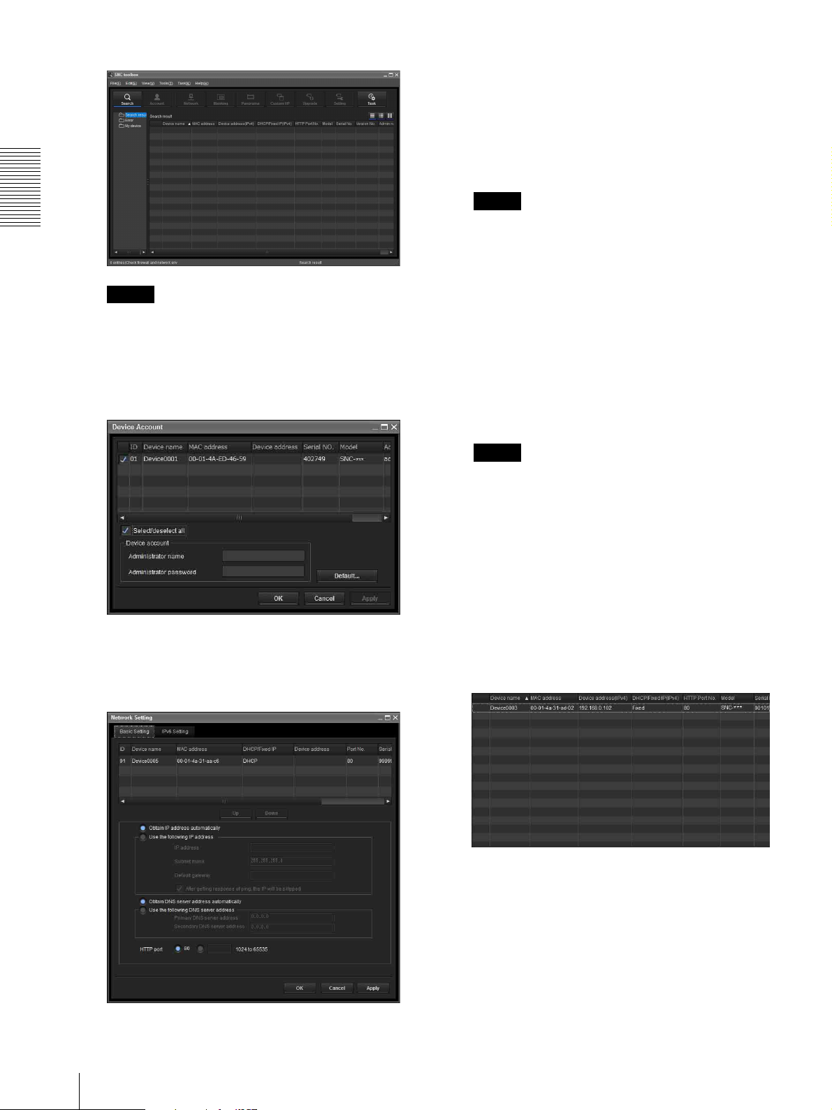
Click Search.
SNC toolbox detects this unit or the camera
connected to the local network and lists them.
Assigning the IP Address to the Unit
5
Page 6
9
Set the IP address.
To obtain the IP address automatically from a
DHCP server:
Select Obtain an IP address automatically.
The IP address, Subnet mask and Default gateway
are assigned automatically.
Note
Preparation
Tip
The factory setting of this unit’s network protocol is
DHCP.
7
Select a unit to which you want to assign an IP
address from the list and click Network.
The account settings screen is displayed.
When you select Obtain an IP address
automatically, make sure that the DHCP server is
operating on the network.
To specify the IP address manually:
Select Use the following IP address, and type the
IP address, Subnet mask and Default gateway in the
relevant boxes.
10
Set the HTTP port No.
Normally, select 80 for the HTTP port No. To use
another port number, type a port number between
1024 and 65535 in the text box.
Note
• To use other than port 80 for this unit, check with
the network administrator first.
• The DNS server address setting that appears for
this unit cannot be used.
11
Confirm that all items are correctly set, then click
OK.
If “Setting OK” is displayed, the IP address is
correctly assigned.
8
Register the name and password of the
administrator and click OK.
The factory settings for both items are “admin.”
The Network Setting screen is displayed.
12
This unit can be directly accessed after settings
have been completed by double-clicking it in the
list.
The setting window of this unit is displayed on the
Web br ow s er.
6
Assigning the IP Address to the Unit
Page 7
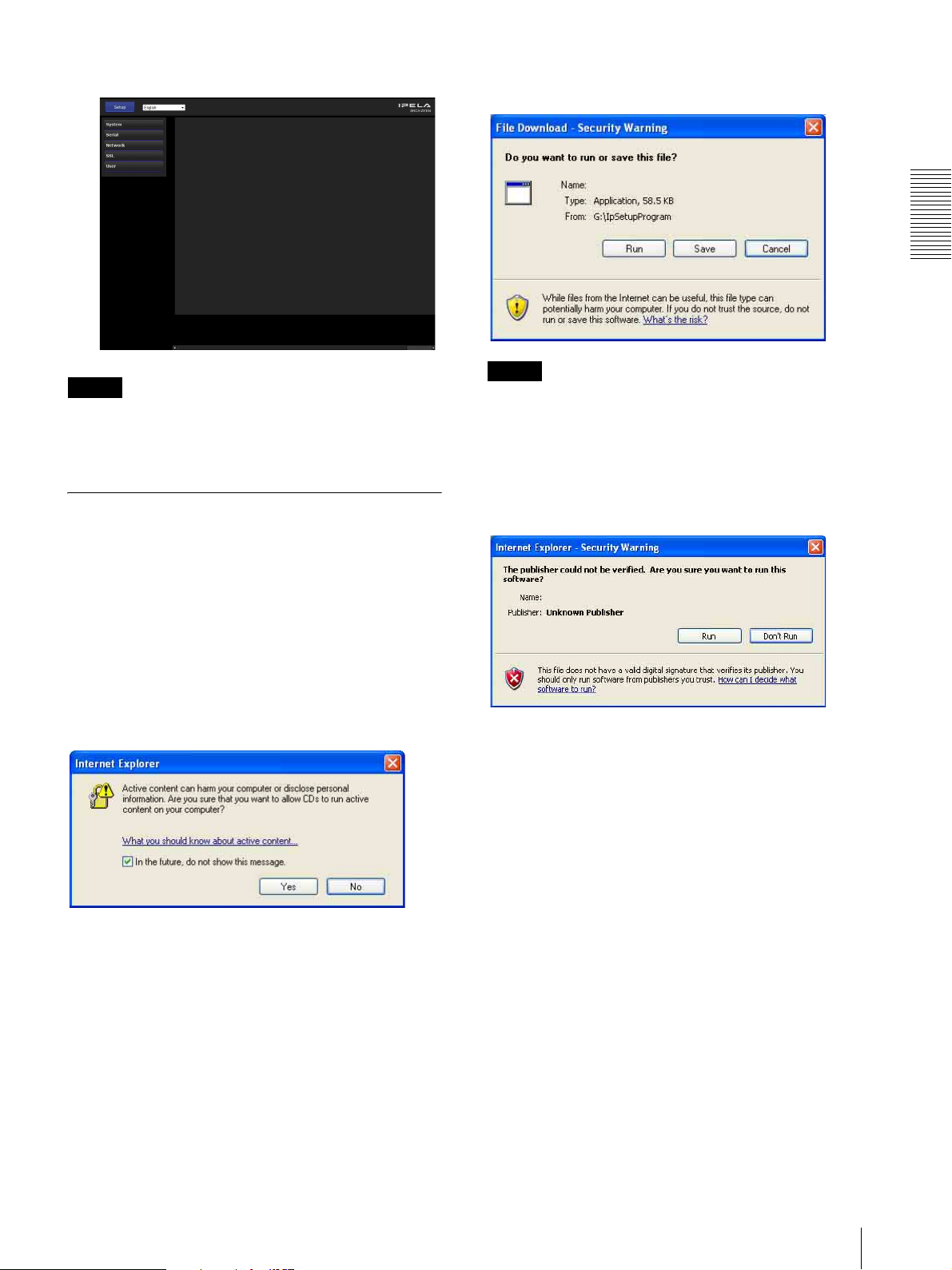
Display sample
If the message “File Download – Security Warning”
appears, click Run.
Program name
Preparation
Note
If the IP address is not set correctly, the setting window
does not appear after step 12. In that case, try to set the
IP address again.
When using Windows XP Service Pack 2 or later
Installing software
A warning message regarding the active contents may
appear when you install software such as SNC toolbox
from CD-ROM. In this case, operate as follows:
Example: In case of SNC toolbox
If message “Internet Explorer” appears, click Yes .
Note
If you select Save in the “File Download – Security
Warning” dialog, you will not be able to perform the
installation correctly. Delete the downloaded file, and
click the Setup icon again.
If the message “Internet Explorer – Security Warning”
appears, click Run.
Program name
The software installation starts.
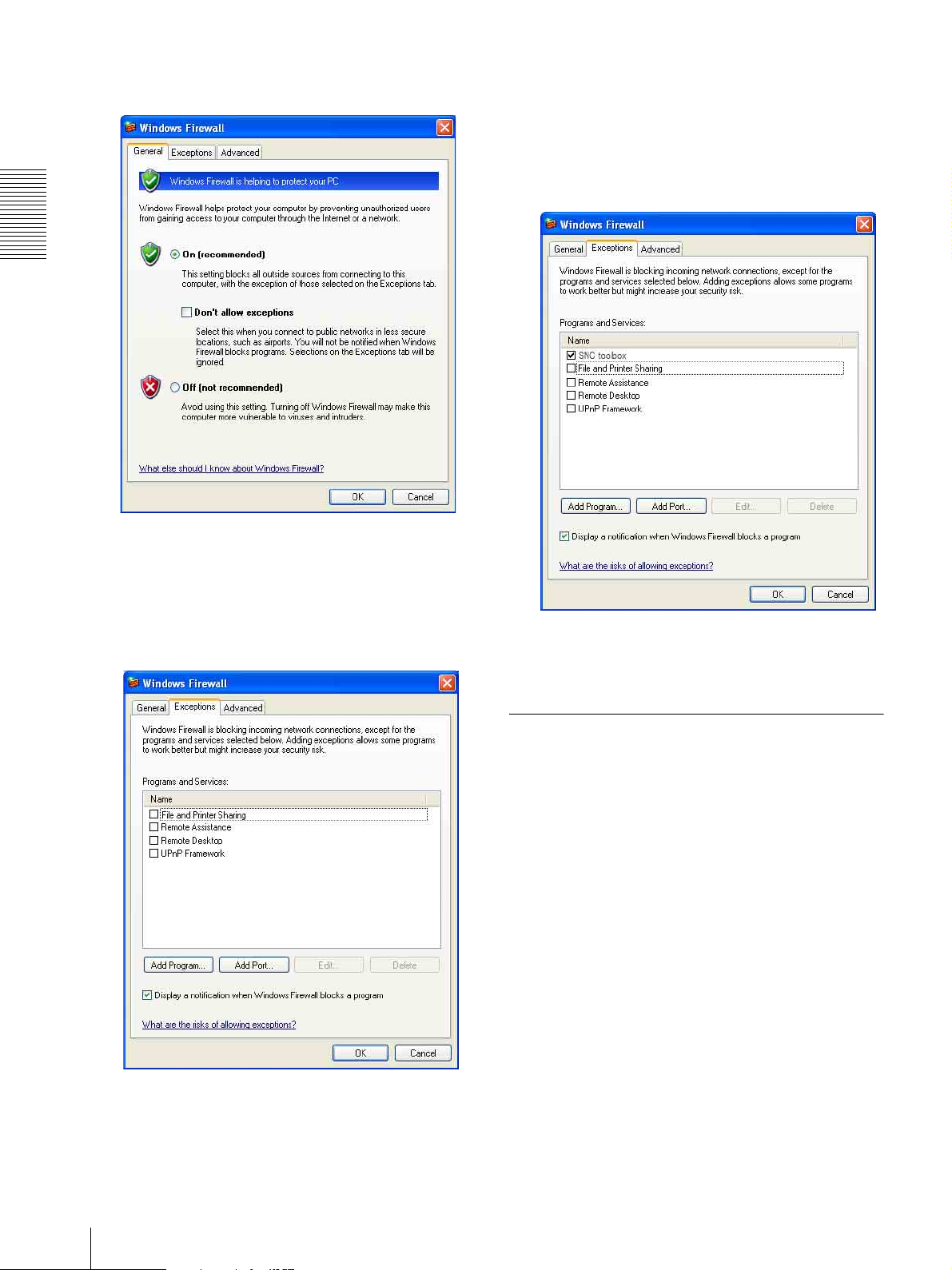
Configuring Windows Firewall
SNC toolbox may not operate correctly depending on
the configuration of Windows Firewall. (This unit may
not be listed even if it is detected.) In this case, confirm
the Windows Firewall configuration as follows:
Example: In case of SNC toolbox
1
Select Control Panel from the Start menu of
Windows.
2
Select Security Center of the working field.
Assigning the IP Address to the Unit
7
Page 8
Preparation
3
Select Windows Firewall and select Off in the
Windows Firewall dialog.
This unit will be listed.
If you want to keep Windows Firewall On, continue
with the following steps.
6
In the Add Program dialog, select SNC toolbox and
click OK.
SNC toolbox is added to the Programs and Services
list.
7
Click OK.
4
Select the “Exceptions” tab.
5
Click Add Program….
When the above procedure is completed, the unit
connected to the local network is displayed in SNC
toolbox.
When using Windows Vista
Installing software
A warning message regarding the active contents may
appear when you install SNC toolbox from the CDROM. In this case, operate as follows:
8
Assigning the IP Address to the Unit
Page 9
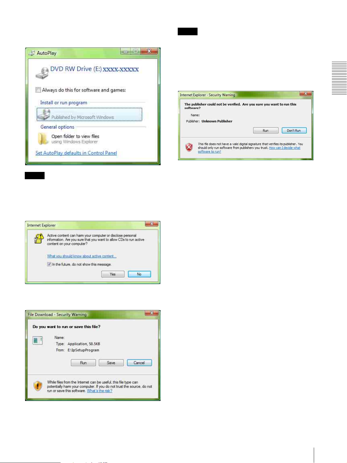
If the pop-up “AutoPlay” appears when a CD-ROM is
inserted into the CD-ROM drive, click Install or run
program.
Note
If you select Save in the “File Download – Security
Warning” dialog, you will not be able to perform
installation correctly. Delete the downloaded file, and
click the Setup icon again.
If the message “Internet Explorer – Security Warning”
appears, click Run.
Preparation
Program name
Note
If you click Open folder to view files, the Web browser
will not open automatically. In this case, double-click
the “index.htm” file in the CD-ROM.
If the message “Internet Explorer” appears, click Yes .
If the message “File Download – Security Warning”
appears, click Run.
Program name
If the message “User Account Control – An unidentified
program wants access to your computer” appears, click
Allow.
The software installation starts.
Starting the software
When you start SNC toolbox, the message “User
Account Control – An unidentified program wants
access to your computer” may appear. In this case, click
Allow.
Configuring Windows Firewall
SNC toolbox may not operate correctly depending on
the configuration of Windows Firewall. (This unit may
not be listed even if it is detected.) In this case, confirm
the Windows Firewall configuration as follows:
1
Select Control Panel from the Start menu of
Windows.
Program name
2
Click Windows Firewall.
3
Select Turn Windows Firewall on or off.
“User Account Control – Windows needs your
permission to continue” may appear. In this case,
click Continue.
Assigning the IP Address to the Unit
9
Page 10

Preparation
4
Select Off in the “General” tab.
8
Click OK.
This unit will be listed.
If you want to keep Windows Firewall On, continue
with the following steps.
5
Select the “Exceptions” tab.
6
Click Add a Program….
7
If the Add a Program dialog appears, select SNC
toolbox and click OK.
When the above procedure is completed, the unit
connected to the local network is displayed in SNC
toolbox.
SNC toolbox is added to the Program or port list.
10
Assigning the IP Address to the Unit
Page 11

When using Windows 7
Installing software
A warning message regarding the active contents may
appear when you install SNC toolbox from the CDROM. In this case, operate as follows:
If the pop-up “AutoPlay” appears when a CD-ROM is
inserted into the CD-ROM drive, click Install or run
program from your media.
If the message “File Download - Security Warning”
appears, click Run.
Preparation
Note
If you select Save in the “File Download - Security
Warning” dialog, you will not be able to perform
installation correctly. Delete the downloaded file, and
click the Setup icon again.
If the message “User Account Control - Do you want to
allow the following program from an unknown
publisher to make changes to this computer?” appears,
click Allow.
Note
If you click Open folder to view files, the Web browser
will not open automatically. In this case, double-click
the “index.htm” file in the CD-ROM.
If the message “Internet Explorer” appears, click Yes .
The software installation starts.
Assigning the IP Address to the Unit
11
Page 12

Configuring Windows Firewall
SNC toolbox may not operate correctly depending on
the configuration of Windows Firewall. (This unit may
not be listed even if it is detected.) In this case, confirm
the Windows Firewall configuration as follows:
To turn Windows Firewall on
1
Select Control Panel from the Start menu of
Windows.
2
Click Windows Firewall.
Preparation
To turn Windows Firewall off
1
Select Control Panel from the Start menu of
Windows.
2
Click Windows Firewall.
3
Select Turn Windows Firewall on or off.
3
Select Allow a program or feature through
Windows Firewall.
4
Select Allow another program....
4
Select Disable Windows Firewall.
The units will be displayed in the list.
12
Assigning the IP Address to the Unit
Page 13

5
Add program.
Accessing the System Using the Web Browser
After the IP address has been assigned to the unit, check
that you can actually access the system using the Web
browser installed on your computer.
Use Internet Explorer as a Web browser.
When the above procedure is completed, the unit
connected to the local network is displayed in SNC
toolbox.
1
Start the Web browser on your computer and type
the IP address of the unit.
The login window is displayed.
2
Enter the user name and password for
Administrator.
The setting window appears.
The user name “admin” and password “admin” are
set at the factory for the Administrator.
Preparation
Display sample
Accessing the System Using the Web Browser
13
Page 14

Preparation
Using the SSL function
Note
The model on sale in China does not support the SSL
function.
When Internet Explorer 6 is used
“Security Alert” dialog may appear according to the
status of the certificate. In this case, click Ye s to
continue.
The setting window is displayed (in SSL
communication).
When Internet Explorer 7 or Internet Explorer 8
is used
When you enter the IP address of the unit, “Certificate
Error” may appear according to the status of the
certificate set on the unit. In this case, click Continue to
this website (not recommended). to continue.
The setting window is displayed (in SSL
communication).
For SSL connection
To display the setting window correctly
To operate the setting window correctly, set the security
level of Internet Explorer to Medium or lower, as
follows:
1
Select To ol s from the menu bar for Internet
Explorer, then select Internet Options and click
the Security tab.
2
Click the Internet icon (when using the unit via the
Internet), or Local intranet icon (when using the
unit via a local network).
3
Set the slider to Medium or lower. (If the slider is
not displayed, click Default Level.)
When using antivirus software, etc., on
the computer
• The Web page displayed when you log in to the unit
uses JavaScript. The display of the Web page may be
affected if you use antivirus software or other software
described above on your computer.
When “Allow HTTP connection for some
clients” (page 19) is checked
To use HTTP and SSL connections separately to access,
enter the following in the address box of the browser.
For HTTP connection
14
Accessing the System Using the Web Browser
Page 15

Administrating the unit
This section explains how to set the functions of the unit.
To set the functions of the unit, use your Web browser
(Internet Explorer).
This section explains the basic operations and each
option of the Setup menu.
Note on the display of menu options
The setting menus of this unit will clearly display only
the setting options that you can select. Grayed out
options cannot be selected.
Basic Operations of the Setup Menu
Logging in
1
Start the Web browser on your computer and type
the IP address of the unit.
Note
If the setting window does not start correctly, the
security level of the Internet Explorer may be set to
higher than Medium. See “To display the setting
window correctly” on page 14 and check the security
level.
Tip
Every page of this software is optimized for Internet
Explorer in Medium font.
3
Click the menu name (example: User) on the left
side of the Setup menu.
The clicked menu appears.
Administrating the unit
The login window is displayed.
2
Enter the user name and password for
Administrator.
The setting window appears.
The user name “admin” and password “admin” are
set at the factory for the Administrator.
Example: “User” menu
See pages 16 to 21 for details of the menu tabs and
setting options.
4
After setting, click OK.
The settings you have made become active.
Click Cancel to nullify the set values and return to
the previous settings.
Buttons common to every menu
The following buttons are displayed on all the menus.
The functions of the buttons are the same on every
menu.
Click this button to confirm the settings.
Basic Operations of the Setup Menu
15
Page 16

Click this button to nullify the set values and return to
the previous settings.
General notes on menus
• One-byte katakana character is not valid for any text
field, such as User name.
• After changing a setting on a menu, wait at least 10
seconds before turning off the power of the unit.
If the power is turned off immediately, the new setting
may not be stored correctly.
Language
Displaying System
Information
Menu
When you click in the Administrator menu, the
System menu appears.
System Tab
System
— System
Administrating the unit
Set language from pull-down.
Configuration of the Administrator menu
System
Displays the System menu. For details, see “Displaying
System Information — System Menu” (page 16).
Serial
Displays the Serial menu for setting Serial PTZ
operations. For details, see “Configuring Serial PTZ
Operations — Serial Menu” (page 17).
Network
Displays the Network menu for setting the network
connection. For details, see “Configuring the Network
— Network Menu” (page 18).
Serial number
The serial number of the unit is displayed.
Software version
The software version of this unit is displayed.
Initialize Tab
Reboot
Used when rebooting the system.
Click Reboot, and the message “This System will be
rebooted. Are you sure?” appears. Click OK to reboot
the unit. It takes about two minutes to restart.
SSL
Displays the SSL menu for performing SSL
communication between the client device and unit.
(“Setting the SSL function — SSL Menu” on page 19)
User
Displays the User menu for setting the log in user name
and password. (“Setting the User — User Menu” on
page 21)
16
Displaying System Information — System Menu
Factory default
Resets the unit to the factory settings.
Retain current network settings
When this item is checked, only the current network
settings will be retained after reset.
Click Factory default, and the message “Setup data will
be initialized. Are you sure?” appears. When you click
OK, the network indicator on the unit starts to blink.
After adjustments of the default settings have finished,
the unit reboots automatically. Do not turn off the unit
until the unit reboots.
Page 17

Tip
The unit can also be reset to the factory settings by
turning on the power of this unit while pressing the reset
button on the unit. For details, see the supplied
Installation Manual.
Backup setting data
Saves the setting data of the unit in a file.
Click Save, and follow the instructions on the Web
browser to specify the folder and save the setting data of
the unit.
The file name preset at the factory is “snca-zx104.cfg.”
Configuring Serial PTZ
Operations
When you click in the Setup menu, the Serial
menu appears.
Use this menu to perform settings related to sending
commands to a camera over a network connection when
receiving analog camera-controlling Pelco-D protocol
commands via the RS-485 port.
Also set devices connected to this system accordingly.
Serial
— Serial Menu
Restore setting
Loads the stored setting data of the unit.
Click Browse and select the file in which the setting data
is stored. Click OK, and the unit is adjusted according to
the loaded data, and restarted.
Note
With Restore setting, some items in the Network menu
(page 18) cannot be restored.
Administrating the unit
RS485 baud rate
Select from 1200, 2400, 4800 or 9600.
Camera list
This list is for converting the camera numbers included
within commands received via the RS-485 port into IP
address and port numbers.
Backup camera list
Saves this unit’s camera list to a file.
Click Save..., and follow the instructions on the Web
browser to specify the folder and save the unit’s camera
list.
Restore camera list
Restores a camera list to this unit that has been saved to
a file.
Click Browse... and select the file in which the camera
list is stored. Click OK to load the selected file and
update the camera list.
Configuring Serial PTZ Operations — Serial Menu
17
Page 18

Administrating the unit
Note
When you click OK next to Browse..., the camera list is
immediately updated. It is unnecessary to click OK at
the bottom of the screen.
To edit the camera list
Set the IP address and port number for each camera
number.
Camera No.: Select from camera 1 to 255.
IP address: Display the selected camera’s IP address.
Click to input the value.
Port: Display the selected camera’s port number. Click
to input the value.
Set: When clicked, the entered address and port number
values are applied to the selected camera if there are
no errors for either value.
Delete: When clicked, the selected camera’s IP address
and port number settings are deleted.
Note
When you click Set, the selected camera’s settings are
immediately updated in the camera list, but these
settings are not saved until you click OK at the bottom
of the screen.
Configuring the Network
— Network Menu
When you click in the Setup menu, the
Network menu appears.
Use this menu to configure the network to connect the
unit and the computer.
MAC address
Displays the MAC address of the system.
Network
OK/Cancel
See “Buttons common to every menu” on page 15.
Ethernet status
Displays the current transmission rate.
IPv4 setting
Configure the IPv4 network setting.
IP address
Configure the IP address.
Obtain an IP address automatically (DHCP): Select
this option when a DHCP server is installed on the
network to allow IP address assignment. With this
setting, the IP address is assigned automatically.
Use the following IP address: Select this option when
you set a fixed IP address. With this setting, specify
the IP address, Subnet mask and Default gateway
manually.
Note
When you select Obtain an IP address automatically
(DHCP), make sure that a DHCP server is operating on
the network.
18
Configuring the Network — Network Menu
IP address
Type the IP address of the system.
Subnet mask
Type the subnet mask.
Page 19

Default gateway
Type the default gateway.
Setting the SSL function
HTTP port number
Normally select 80. If you want to use a port number
other than 80, select the text box and type a port number
between 1024 and 65535.
Note
When you have set the HTTP port number to a number
other than 80 in the Network menu or in SNC toolbox,
access the system again by typing the IP address of the
unit on your Web browser as follows:
Example: Setting port number 8000 when IP address is
192.168.0.100
IPv6 setting
Configure the IPv6 network settings.
IPv6 can be used simultaneously with IPv4.
Only IPv6-specific details are explained here. For
common details, see “IPv4 setting” on page 18.
— SSL Menu
When you click in the Setup menu, the SSL menu
appears.
Use this menu to configure the SSL or TLS function.
(called “SSL” hereafter) The settings allows the unit to
communicate with the client PC by using SSL.
Note
The model on sale in China does not support the SSL
function.
Setting tab
SSL
Administrating the unit
On/Off
To use IPv6, select On.
Prefix
Enter the Prefix value. (0 to 128)
OK/Cancel
See “Buttons common to every menu” on page 15.
SSL function
On: Select this to use the SSL function. When Allow
HTTP connection for some clients is selected, both
HTTP and SSL connections are allowed. When
Allow HTTP connection for some clients is not
selected, only SSL connection is allowed.
When Microsoft Internet Explorer Ver.6.0 is used
When SSL session is established, appears in the
status bar on your web browser.
When Microsoft Internet Explorer Ver.7.0 or
Internet Explorer Ver.8 is used
When SSL session is established, appears in the right
of the address bar on your web browser.
Off: Select this to not use the SSL function. Only HTTP
connection is allowed with the unit.
When you use SSL connection for the first time
When you use SSL connection only with the SSL
function On, you cannot access the unit if the SSL
function does not work properly.
In this case, you must reset the unit to the factory
settings. (All settings will be initialized.)
Setting the SSL function — SSL Menu
19
Page 20

Administrating the unit
To avoid this, check that SSL connection is possible by
performing the following steps.
1
Set the SSL function to On, and select Allow
HTTP connection for some clients.
2
Click OK to close the setting window.
3
Display the setting window in SSL connection.
Refer to “Using the SSL function” on page 14 for
connection.
4
After checking that SSL connection is possible,
cancel Allow HTTP connection for some clients
selected in step 1.
Even if the setting window or the browser is closed as
SSL connection is impossible, http connection will be
possible if Allow HTTP connection for some clients is
selected. First check the setting contents of Setting tab in
http connection, then check the SSL connection again.
Status
Shows if the status of the certificate is valid or invalid.
The following statuses are recognised.
Val id : The certificate is correctly stored and set.
Invalid: The certificate is not correctly stored and set.
Possible causes are as follows:
– The private key password included in the
certificate is not specified correctly.
– The private key password is specified in spite of
the fact that the key pair in the certificate is not
encrypted.
– The key pair is not included in the certificate.
Note
When the certificate to be imported is of PKCS#12
format and the private key password is not set correctly,
<Put correct private key password> is displayed in the
boxes of Issuer DN, Subject DN, Validity Period and
Extended Key Usage. Specify the correct private key
password to confirm the information of the certificate.
If Allow HTTP connection for some clients is not
selected, you will not be able to access the unit if SSL
connection becomes impossible. In this case, turn on the
power of the main unit while pressing the reset switch on
the unit to initialize. For details, refer to the supplied
Installation Manual.
Notes
• Even if the SSL function is set to On, it is not active in
the following cases:
When the certificate and the private key password are
not set properly.
• SSL connection may be impossible due to the type of
certificate installed in the unit.
Certificates
Import, display or delete the certificate.
To import the certificate
Click Browse... to select the certificate to be imported.
Click Submit to import the certificate, and the selected
file to the unit.
Note
The import process becomes invalid if the selected file is
not a certificate or the imported certificate is not
allowed. The PKCS#12 and PEM formats are supported.
To display certificate information
When the certificate has been set in the unit correctly, its
information appears on Status, Issuer DN, Subject DN,
Validity Period and Extended Key Usage.
To delete the imported certificate
Click Delete to delete the certificate imported to the
unit.
Private key password
Type the password for the private key information
included in the certificate using up to 50 characters.
Leave the text box blank if the private key information
included in the certificate is not encrypted.
If no private key password is set in the unit, an active text
field is displayed and this allows a password to be
entered.
If a private key password is already set, it is displayed as
an inactive text field.
Reset
To change the private key password, click this button.
The current password is cleared and the password text
box becomes active to allow a new password entry.
Note
Click Cancel at the bottom of the menu if you want to
cancel changing the private key password after clicking
Reset. Doing so restores the other setting items in the
Setting tab to the previous settings.
OK/Cancel
See “Buttons common to every menu” on page 15.
Note
When you click OK after changing SSL setting, close
the setting window once.
20
Setting the SSL function — SSL Menu
Page 21

Setting the User
— User Menu
When you click in the Setup menu, the User menu
appears.
Use this menu to set Administrator user names and
passwords.
User
Administrator
Specify User name, Password and Re-type password.
User name
Type a user name between 5 and 16 characters.
Password
Type a password between 5 and 16 characters.
Re-type password
To confirm the password, retype the password that you
typed in the Password box.
Administrating the unit
OK/Cancel
See “Buttons common to every menu” on page 15.
Setting the User — User Menu
21
Page 22

Others
This section explains how to use the application
software, including the supplied CD-ROM.
Using the SNC toolbox
Explains the functions except those of the Network tab
in SNC toolbox.
To install SNC toolbox, to assign an IP address and to set
the network, see “Assigning the IP Address to the Unit”
on page 5 in “Preparation.”
How to use SNC toolbox
Menu bar Function buttons
Device tree display Device list View button
Notes
Menu bar
Others
• SNC toolbox may not operate correctly if you use a
personal firewall or antivirus software in your
computer. In this case, disable the software.
• If you are using Windows XP Service Pack 2 or later,
Windows Vista or Windows 7, disable the Windows
Firewall function. Otherwise SNC toolbox will not
operate correctly. For the setting, see “Configuring
Windows Firewall” in “When using Windows XP
Service Pack 2 or later” on page 7, “Configuring
Windows Firewall” in “When using Windows Vista”
on page 9 or “Configuring Windows Firewall” in
“When using Windows 7” on page 12.
• The model on sale in China does not support the SSL
function.
Starting SNC toolbox
Select All Programs from the Start menu of Windows,
then select SNC toolbox and SNC toolbox in sequence.
SNC toolbox starts.
The main screen appears. SNC toolbox detects the unit
or the camera connected to the local network and lists
them on the Network tab window.
All functions can be selected from here.
File (F) menu
Close: Exits SNC toolbox.
Edit (E) menu
Select All: Selects all devices in the Device list.
View (V) menu
Status Bar: Switches show/hide of status at the bottom
of the screen.
Column Setting: Displays the setting screen for the
items to display on the list.
Tools (T) menu
Search: Searches again for devices.
Device Account: Displays the management screen for
user names and passwords related to the device.
Network Setting: Displays the screen for modifying the
address settings for the selected device.
Custom Homepage: Displays the Custom Homepage
screen.
When you are using Windows Vista, message “User
Account Control – An unidentified program wants
access to your computer” may appear. In this case, click
Allow.
22
Using the SNC toolbox
Note
The Custom Homepage setting cannot be used with this
unit.
Firmware Upgrade: Displays the Firmware Upgrade
screen.
Device Homepage: Connects to the device.
Tool Log: Obtains SNC toolbox log.
Option: Displays the screen for modifying SNC toolbox
settings.
Help (H) menu
Ver si on: Displays SNC toolbox version information.
Page 23

Function buttons
Function buttons are used for updating lists and
displaying dialog.
Status (Only for Error folder and My device
folder)
You can check the current connection status.
Search
Updates the Device list in the search result.
Account
Sets the administrator for each device.
Network
Displays the Network Setting dialog.
Custom HP
Displays the Custom Homepage dialog.
Upgrade
Updates the device firmware.
Note
The Custom Homepage setting cannot be used with this
unit.
Device tree view
This function allows you to customize folders. The
registration details of My device can be displayed in tree
format.
MAC address
You can check the MAC address of the device.
Device address
You can check the IP address of the device.
HTTP Port No.
You can check the port number of the device.
DHCP/Fixed IP
Displays whether the IP address of the selected device is
DHCP or fixed IP.
Model
Displays the model name.
Serial No.
Displays the serial number.
Version No.
Displays the version of firmware.
Admin name
Displays the administrator user name.
Others
Search result folder
When this folder is selected, devices in the same
segment detected at time of startup or by Search are
displayed in the Device list.
Error folder
When this folder is selected, devices registered in My
device folder that can not be connected are displayed in
the Device list.
Also, if a registered device is not found on the network,
it will also be registered in this folder.
My device folder
When this folder is selected, devices in the Search result
folder or registered manually are displayed in the Device
list.
Device list
Devices registered in the folder selected at Device tree
view are displayed in a list.
Device name
Displays individual device names.
IP Address of NIC (Search result folder only)
Displays the IP address of the NIC (Network Interface
Card) detected.
Tips
• A unit with which SSL communication has been
performed will show on the left side of its IP
address.
• The model on sale in China does not support the SSL
function.
View button
You can change the display format of the Device list.
Registering in My device
The device tree has three folders by default: Search
result, Error and My device.
The Search result folder and Error folder are fixed, so
you cannot edit the content or rename the folder.
The My device folder can be renamed, and you can add,
delete and move folders.
Search result folder
Displays devices detected by search.
Using the SNC toolbox
23
Page 24

Error folder
Displays devices that are not connected.
My device folder
You can sort and manage devices using any folder.
Adding a folder
1
Select the parent folder to which you want to add a
folder.
2
Right click the mouse and select Add Folder from
the displayed menu.
A folder is added. Enter a folder name of your
choice.
Registering a device
To register a device, follow the procedure below:
• Registering by Add Device Entry dialog
Others
• Registering by drag & drop
• Registering by copy & paste
Registering by Add Device Entry dialog
1
Select the folder to register the device.
2
Right click the mouse and select Add Device Entry
from the displayed menu.
The Add Device Entry dialog appears.
more than one unit in the specified IP address range
then select Multi device.
HTTP port No.: Normally, 80 should be selected.
When setting a value other than 80, select the
textbox and enter a port number.
HTTPS port No.: Normally select 443. When
setting a value other than 443, select the textbox
and enter a port number.
Protocol: Select communication protocol HTTP
or HTTPS.
Client certificate: Set when using the client
authentication of the SSL function.
Activates when HTTPS is selected.
Default certificate: Select Default client
certificate of the Network tab from Option in
the To ol s menu.
Certificate of IE: Press the IE certificates...
button, then select the certificate registered in
the Internet Explorer.
Device account: Enter the user name and password
of the administrator who will access the device in
the Administrator name field and Administrator
password field, respectively.
4
Click OK to finish registration.
Registering by drag & drop
To add a device, select a device from the Device list in
the Search result folder, and drag & drop to the folder to
register it in.
3
Enter the following items:
Device name: Enter a device name of your choice.
Device address: Enter the address of the device to
register. Normally, select Single device. If there is
Registering by copy & paste
Select a device from the Device list in the Search result
folder and right click the mouse. Select Copy from the
displayed menu (or select Copy from the Edit menu).
Next, select the folder to register in and right click the
mouse. Select Paste from the displayed menu.
Renaming the device/folder
Select the folder or device to rename and right click the
mouse. Select Rename from the displayed menu. The
device/folder name is highlighted. Enter the new name.
Deleting a device/folder
Select the device/folder to be deleted from the Device
list or Device tree and right click the mouse. Select
Delete from the displayed menu (or select Delete from
the Edit menu).
Moving a device/folder
You can move a device/folder by following either of the
methods below:
• Select a device/folder from the Device list or Device
tree and drag & drop in the folder to move it to, which
will move the device/folder.
24
Using the SNC toolbox
Page 25

• Select a device/folder from the Device list or Device
tree and right click the mouse. Select Cut from the
displayed menu (or select Cut from the Edit menu).
Next, select the folder to move to and select Paste.
Changing the Device list display method
Modifying the items to show on list
Select Column setting from the View menu to display
the “Column Setting” dialog.
Default device account
Set the initial values of user name and password for the
administrator accessing the device for each device.
Firmware upgrade
Configure the firmware upgrade.
Device setting backup folder: Set the destination to
save the configuration file when upgrading. Click
Browse, and the dialog to select the folder is
displayed to allow you to set the folder to save the
file.
Show warning dialog when close main window:
Select to display the warning message.
Remind me the risk when assign IP: Select to display
the warning message.
Network tab
Check the items you want to display and remove the
checks from items you want to hide.
Click OK after making the changes. The new setting is
reflected on the list and the display returns to the main
screen.
Setting SNC toolbox options
Select Option from the Tools menu to display the
“Option” dialog. This dialog consists of 3 types:
General, Network and Log.
General tab
Others
Configure the HTTP proxy.
When using HTTP proxy, check Use HTTP proxy.
To auto-detect the proxy server, select On for Auto
detect.
If you are not auto-detecting the proxy server, select Off
for Auto detect, and enter the proxy address and proxy
port number.
Language
Set language.
IP configuration
Select the IP address used for the Search result folder.
IPv4: Uses IPv4.
IPv6 priority: Uses IPv6. Uses IPv4 if IPv6 is not
selected.
SSL Setting
Configure the SSL setting.
Default client cerfificate: Enter the client certificate to
use.
Using the SNC toolbox
25
Page 26

How to process SSL errors in scheduled task or main
window: Select Continue or Cancel.
When SSL function of device is SSL only, allow to
switch from HTTP protocol to HTTPS protocol
automatically: Check this box if necessary.
Notes
• When you have changed the SSL setting, restart the
SNC toolbox.
• The model on sale in China does not support the SSL
function.
Log tab
Device list Module list
Others
Overwrite the oldest log file
To set the size of the log file, check Enable and specify
the minimum required space for a log file.
Log output folder
Click Browse to display the folder selection dialog.
Specify the folder to save the log.
Tip
The Firmware Upgrade screen can also be displayed
using the following method:
• Select Firmware Upgrade from the To ol s menu.
Device list
Select the device to upgrade.
A progress bar is displayed when upgrading is in
process.
The status field shows current status.
Module list
To display the dialog, click the Browse button on the
right side of the model to upgrade (listed in the module
list). Select the target SVU file from the dialog.
You can select one file for each model.
Upgrading
1
Set the order of devices perform upgrade using Up
and Down.
Using the Firmware Upgrade
2
Using the Firmware Upgrade function of the SNC
toolbox allows you to upgrade the firmware of the
device.
Starting the Firmware Upgrade
1
Select the device to upgrade its firmware from the
Device list.
You can select multiple devices at the same time.
2
Right click the mouse. Click Firmware Upgrade
from the displayed menu.
The Firmware Upgrade screen is displayed.
Click Browse and select an upgrade file for each
model.
3
Select how many devices to upgrade in Paralleled
upgrade quantity.
4
To back up the device setting, check Backup
device setting.
Tip
Select General from Option in the To ol menu to
set Device setting backup folder.
26
Using the SNC toolbox
Page 27

5
Click Start Upgrading.
Upgrading starts.
Notes
Glossary
• To stop upgrading, click Stop upgrading.
To protect some devices, during the process of
upgrading, upgrading cannot be canceled.
• Do not turn off the power until the device restarts after
upgrading.
• While upgrading a connected camera, do not upgrade
this unit.
Default gateway
Device that can be used to access another network.
DHCP server
Acronym for Dynamic Host Configuration Protocol
server. The IP address of a terminal without an
individual IP address can be automatically distributed by
the Dynamic Host Configuration Protocol (DHCP). The
DHCP server assigns the IP addresses to the terminals.
Digital certificate
An electronic certificate that a CA (Certificate
Authority) attests that a public key to cancel a secret
code is issued by an authentic publisher.
DNS server
Acronym for Domain Name System server. As an IP
address required for connecting to the device on an IP
network is numerical and difficult to remember, the
Domain Name System was established. A domain name
is alphabetic and is easier to remember. When a client
computer uses a domain name to connect to another
computer, it asks a DNS server to translate the name into
the corresponding IP address. The client computer can
then obtain the IP address of the computer to be
connected.
Others
HTTP port
A port used to communicate between the web server and
the web client, such as a web browser.
IP address
Acronym for Internet Protocol Address. An individual
IP address is basically assigned to each piece of
equipment connected to the Internet.
MAC address
A network address that uniquely identifies each LAN
card.
Network address
The portion that identifies the local network (subnet) in
an IP address.
Primary DNS server
One of the DNS servers that can first reply to a request
by connected devices or other DNS servers.
Glossary
27
Page 28

RS-485
A serial communications standard defined by the EIA
(The Electronic Industries Alliance) in the U.S.
Secondary DNS Server
Subsidiary DNS server used when a primary DNS server
cannot be used.
SLOC
Abbreviation for Security Link over Coax.
SLOC is a technology that enables analog composite
video images and digital IP signals to be sent
simultaneously using just one coaxial cable. It was
developed by Intersil Corporation.
SSL
Acronym for Secure Sockets Layer. This is a protocol
developed by Netscape Communications Corporation to
Others
be used for communications of encrypted data on the
Internet.
Subnet mask
32-bit stream used to distinguish the subnet address
from an IP address.
28
Glossary
Page 29

Index
R
Re-type password........................... 21
RS485 baud rate............................. 17
A
Administrator ................................. 21
C
Camera list ..................................... 17
Cancel button ................................. 16
D
Default gateway ............................. 19
DHCP......................................... 6, 18
DHCP server .................................. 18
Digital certificate ........................... 27
DNS server..................................... 27
E
Ethernet status................................18
F
Firmware Upgrade ......................... 26
H
S
Secondary DNS Server .................. 28
Security Warning....................7, 9, 11
Serial number ................................. 16
Setup Menu .................................... 15
SLOC ............................................. 28
SNC toolbox................................... 22
Software version ............................16
SSL...........................................19, 28
Subnet mask ................................... 18
System............................................ 16
U
User .......................................... 16, 21
User name ......................................21
W
Windows 7 ..................................... 11
Windows Firewall .................. 7, 9, 12
Windows Vista ................................. 8
Windows XP Service Pack 2............ 7
Others
HTTP port ...................................... 27
HTTP port number..................... 6, 19
I
Internet Explorer ............................ 13
IP address............................. 5, 18, 27
IPv4 setting ....................................18
M
MAC address............................ 18, 27
N
Network....................................16, 18
Network address............................. 27
O
OK button....................................... 15
P
Password ........................................ 21
Primary DNS server....................... 27
Sony Corporation
Index
29
 Loading...