

Sony SNCA-HRX550/EXT, SNCA-HRX550EXT/W, SNCA-HRX550/INT Installation And Operation Instructions Manual

Installation and Operation Instructions for the following model:
SNCA-HRX550/EXT, SNCA-HRX550/INT,
& SNCA-HRX550EXT/W
Outdoor and Indoor Dome Housings
SNCA-HRX550/EXT Outdoor Pendant Housing with heater & blower, clear lower dome
SNCA-HRX550/INT Indoor Pendant Housing with heater & blower, tinted lower dome
SNCA-HRX550EXT/W Outdoor Pendant Housing with heater & blower, clear lower dome,
and a wireless antenna cable
Note: AC 24V power supply for the camera and the heater/blower is an installer/re-seller
provided item. Please refer to Electrical Specifications for power consumption details.
Indoor models do not have heater/blower or pre-run cables.
Note: Please note that to achieve the increased depth with the aspheric design for optimal
camera lens to capsule orientation, the capsule is slightly angled around the highest
section. This creates a ”line’, visible to the naked eye, around the upper most section
of the capsule. This “line” serves as the geometric center line used to insure proper
camera placement. It is not typically seen by the camera. However, Sony RZ series PTZ
cameras are able to tilt up above the horizon to 25°, this wide range of tilt motion at
a wide angle view may cause this line to be captured in the image.
Mounting instructions for:
SNC-RZ25
SNC-RX530, 550, 570
SNC-RS44, 46
SNC-RH124
SNC-EP580, 550, 520
SNC-ER580, 550, 520
81-IN6605 12202011
IMPORTANT SAFEGUARDS SAFETY PRECAUTIONS
1 Read instructions - All the safety and operating
instructions should be read before the unit is
operated.
2 Retain instructions - The safety and operating
instructions should be retained for furture reference.
3 Heed Warnings - All warnings on the unit and in the
operating instructions should be adhered to.
4 Follow instructions - All operating and user instructions
should be followed.
5 Ellectrical Connections - Only a qualified electrician
should make electrical connections.
6 Attachments - Do not use attachments not
recommended by the product manufacturer as they
may cause hazards.
7 Cable Runs- All cable runs must be within permissible
distance.
8 Mounting - This unit must be properly and securely
mounted to a supporting structure capable of
sustaining the weight of the unit.
Accordingly:
a. The installation should be made by a qualified
installer.
b. The installation should be in compliance with local
codes.
c. Care should be exercised to select suitable
hardware to install the unit, taking into account
both the composition of the mounting surface and
the weight of the unit.
Be sure to periodically examine the unit and the supporting
structure to make sure that the integrity of the installation is
intact. Failure to comply with the foregoing could result in
the unit separating from the support structure and falling,
with resultant damages or injury to anyone or anything
struck by the falling unit.
UNPACKING
Unpack carefully. Electronic components can be
damaged if improperly handled or dropped. If an item
appears to have been damaged in shipment, replace
it properly in its carton and notify the shipper.
Be sure to save:
1 The shipping carton and packaging material.
They are the safest material in which to make
future shipments of the equipment.
2 These Installation and Operating Instructions.
SERVICE
If technical support or service is needed, contact
Sony at the following number:
TECHNICAL SUPPORT
8:15 AM to 7:30 PM
(Eastern Time)
1- 800 - 883 - 6817
CAUTION: TO REDUCE THE RISK OF
ELECTRIC SHOCK, DO NOT REMOVE
COVER ( OR BACK). NO USER- SERVICE-
ABLE PARTS INSIDE. REFER SEVICING TO
QUALIFIED SERVICE PERSONNEL.
The lightning flash with an arrowhead
symbol, within an equilateral triangle, is
intended to alert the user to the presence
of non-insulated “dangerous voltage”
within the product’s enclosure that may be
of sufficient magnitude to constitute a risk
to persons.
Este símbolo se piensa para alertar al usuario a la
presencia del “voltaje peligroso no-aisIado” dentro del
recinto de los productos que puede ser un riesgo de
choque eléctrico.
Ce symbole est prévu pour alerter I’utilisateur à la
presence “de la tension dangereuse” non-isolée dans la
clôture de produits qui peut être un risque de choc
électrique.
Dieses Symbol soll den Benutzer zum Vorhandensein der
nicht-lsolier “Gefährdungsspannung” innerhalb der
Produkteinschließung alarmieren die eine Gefahr des
elektrischen Schlages sein kann.
Este símbolo é pretendido alertar o usuário à presença
“di tensão perigosa non-isolada” dentro do cerco dos
produtos que pode ser um risco de choque elétrico.
Questo simbolo è inteso per avvertire I’utente alla
presenza “di tensione pericolosa” non-isolata all’interno
della recinzione dei prodotti che può essere un rischio di
scossa elettrica
The exclamation point within an equilateral
triangle is intended to alert the user to
presence of important operating and
maintenance (servicing) instructions in the
literature accompanying the appliance.
Este símbolo del punto del exclamation se piensa para
alertar al usuario a la presencia de instrucciones
importantes en la literatura que acompaña la
aplicación.
Ce symbole de point d’exclamation est prévu pour
alerter l’utilisateur à la presence des instructions
importantes dans la littérature accompagnant
l’appareil.
Dieses Ausruf Punktsymbol soll den Benutzer zum
Vorhandensein de wichtigen Anweisungen in der
Literatur alarmieren, die das Gerät begleitet.
Este símbolo do ponto do exclamation é pretendido
alertar o usuário à presença de instruções importantes
na literatura que acompanha o dispositivo.
Questo simbolo del punto del exclamaton è inteso per
avvertire l’utente alla presenza delle istruzioni importanti
nella letteratura che accompagna l'apparecchio.
Manufactured exclusively for Sony Electronics by:
Videolarm, Inc
2525 Park Central
Decatur, GA 30035
CAUTION
RISK OF ELECTRIC SHOCK
DO NOT OPEN
.
©2007 Sony Corporation
Contents of Box Details
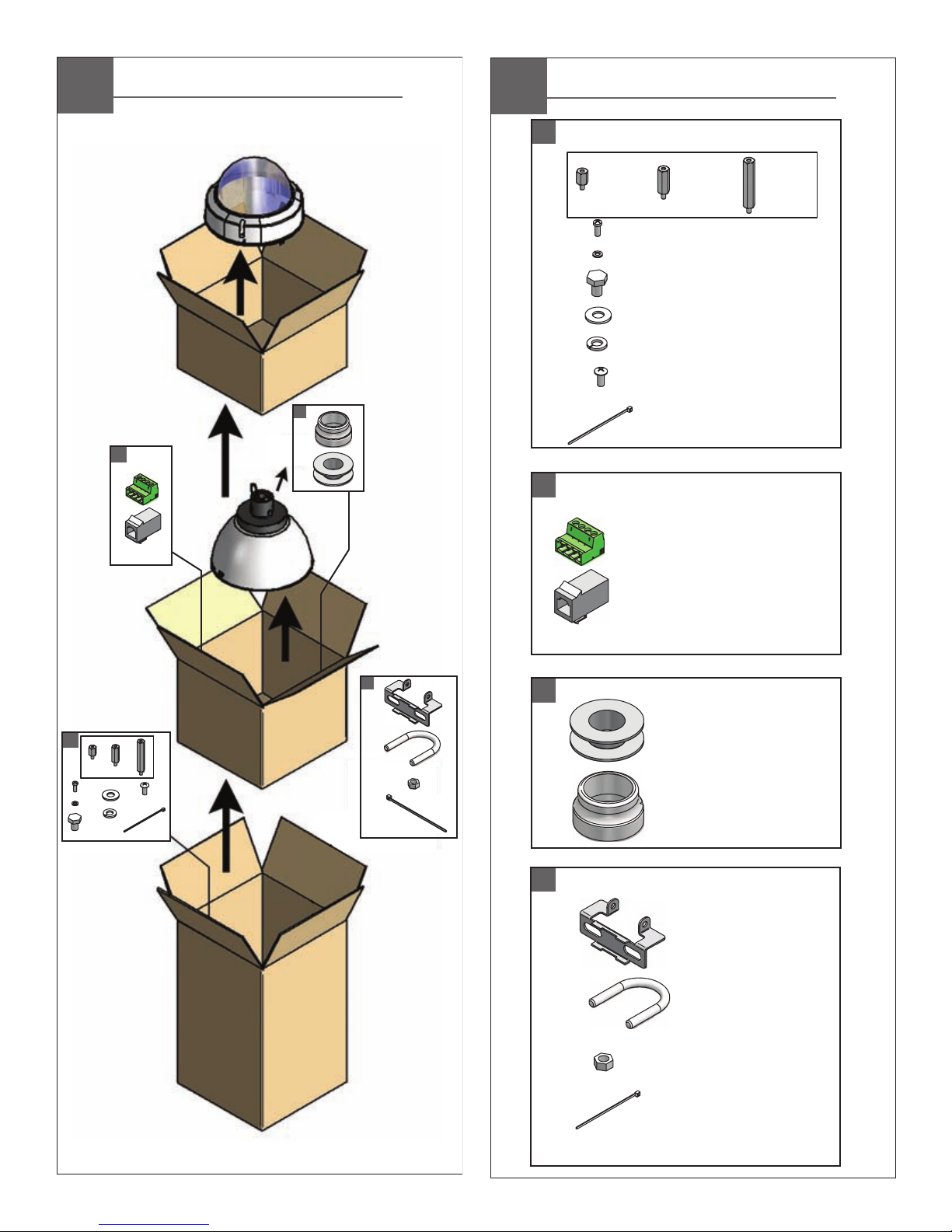
Contents of Box
A
B
C
D
*
A
(1) Spacer Packet
½”
(4)
25mm
(4) M3 x 6mm Machine Screw
(4) M3 lock washers
(1) 1/4 x 20 Bolt
(1) 1/4 flat washer
(1) 1/4 lock washer
(3) 8 x 32 x 3/8" bolt
(8)
1”
50mm
(4)
200mm
2”
(3) Cable ties
B
(1) 4 Pin Power Connector
(1) RJ45 Coupling
C
(1) Teflon Tape
(1) Pendant Gasket
*
D
*
(1) WiFi Bracket
(1) 5/16 x 18 U-Bolt
* Wireless units only
(2) 5/16 x 18 Nut
(2) Cable Tie
SNCA-HRX550/EXT
SNCA-HRX550EXT/W
SNCA-HRX550/INT
Electrical Specifications
(ONLY AL AIRE LIBRE):
SNCA-HRX550/EXT, SNCA-HRX550EXT/W
26 vatios en 24VAC (calentador y soplador)
25 vatios en 24VAC (cámara fotográfica)
(ONLY DE INTERIOR):
SNCA-HRX550/INT
Vea Las Especificaciones De la Cámara fotográfica.
Herramientas Requeridas: Destornillador PrincipalPhillips
Del Destornillador Principal Plano Del 100"
(ONLY EXTÉRIEURS):
SNCA-HRX550/EXT, SNCA-HRX550EXT/W
26 watts à 24VAC (réchauffeur et ventilateur)
25 watts à 24VAC (appareil-photo)
(ONLY D'INTÉRIEUR):
SNCA-HRX550/INT
Voir Les Caractéristiques D'Appareil-photo.
Outils Requis: Tournevis Principal Phillips
De Tournevis Principal Plat De 100"
(IM FREIEN ONLY):
SNCA-HRX550/EXT, SNCA-HRX550EXT/W
26 Watt an 24VAC (Heizung und Gebläse)
25 Watt an 24VAC (Kamera)
(INNENONLY):
SNCA-HRX550/INT
Sehen Sie Kamera-Spezifikationen.
Werkzeuge Erforderten: 100"Flacher Hauptschraubenzieher-
Kreuzkopfhauptschraubenzieher
(ONLY AO AR LIVRE):
SNCA-HRX550/EXT, SNCA-HRX550EXT/W
26 watts em 24VAC (calefator e ventilador)
25 watts em 24VAC (câmera)
(ONLY INDOOR):
SNCA-HRX550/INT
Veja Especificações Da Câmera.
As Ferramentas Requereram: Chave de fenda Principal
Phillips Da Chave de fenda Principal Lisa Do 100"
(ONLY ESTERNI):
SNCA-HRX550/EXT, SNCA-HRX550EXT/W
26 watt a 24VAC (riscaldatore e ventilatore)
25 watt a 24VAC (macchina fotografica)
(ONLY DELL'INTERNO):
SNCA-HRX550/INT
Veda Le Specifiche Della Macchina fotografica
Attrezzi Richiesti: Cacciavite Capo "phillips" Del Cacciavite
Capo Piano Del 100"
(OUTDOOR ONLY):
SNCA-HRX550/EXT
SNCA-HRX550EXT/W
Power 24VAC, Class 2 Only
26 Watts at 24 VAC (Heater and Blower)
25 Watts at 24 VAC (Camera)
(INDOOR ONLY):
SNCA-HRX550/INT
Tools Required: .100" Flat Head Screwdriver
Phillips Head Screwdriver
See Camera Specifications.
1
UNINL7C2 &
UNINL7T2
There are no pre-run cables on the indoor
SNCA-HRX550/INT
models.
• Hay ningún pre-funciona los cables en los modelos de interior.
Continúe con la sección de instalación de la cámara)
(
• Il y a aucun pré-courent des câbles sur les modèles d'intérieur.
Passez à la section Installation de caméra)
(
• Es gibt kein vor-laufen lassen Kabel auf den Innenmodellen.
(Fahren Sie mit Kamera Installations-Abschnitt)
• Há nenhum pre-funciona cabos nos modelos indoor.
Continue na seção Instalação da câmara)
(
• Ci è nessun pre-fa funzionare i cavi sui modelli dell'interno.
Procedere alla sezione di installazione della fotocamera)
(
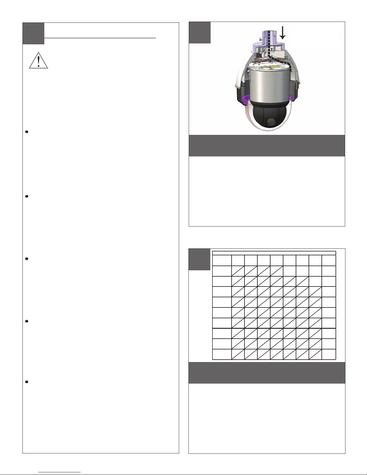
2
These are recommended maximum distances
for 24VAC with a 10% voltage drop.
• Éstos se recomiendan las distancias máximas para
24VAC con una caída de voltaje del 10%.
• Ceux-ci sont recommandés des distances maximum
pour 24VAC avec une chute de tension de 10%.
• Diese werden maximale Abstände für 24VAC mit
einem 10% Spannungsabfall empfohlen.
• Estes são recomendados distâncias máximas para
24VAC com uma queda de tensão de 10%.
• Questi sono suggeriti distanze massime per 24VAC con
una differenza de potenziale di 10%.
(Proceed to Camera Installation section)
Total vA
consumed
5.5
10
20
30
40
50
60
70
80
ft
120
86
65
44
35
29
25
31
,5
22
36.5
27.1
19.8
13.4
10.6
9.4
8.8
7.6
400
m
180
141
90
70
56
47
40
34
Wire Gauge
,75201,0181,5162,514412610MM
600
960
121
54.9
43.0
27.4
21.3
17.1
14.3
12.2
10.3
300
225
130
112
90
75
64
55
182
91.4
68.6
39.6
34.1
27.4
22.9
19.5
16.8
480
358
225
179
143
119
102
85
292
146
109
68.6
54.6
43.6
36.2
31.1
25.9
- - -
800
1300
243
396
571
905
174
275
350
525
106
160
285
452
86.9
138
228
362
69.5
110
190
301
57.9
91.7
163
258
49.7
78.6
140
215
42.7
65.5
1440
830
720
576
480
411
340
-
438
252
219
175
146
125
103
2
AWG
1/2” Spacers
or standoffs
Add (4) 1/2” spacers, align tabs in mounting plate and turn counterclockwise then secure.
• Añadir (4) 1 / 2 "de separación, se suman las pestañas en la placa de montaje y gire en sentido entonces seguro.
• Ajouter (4) 1 / 2 "d'espacement, l'alignement des onglets dans la plaque de montage et de tourner dans le sens
antihoraire sécurisée.
• "Hinzufügen" (4) 1 / 2 "Abstandhalter, Angleichung der Registerkarten in Montageplatte und dann gegen den
Uhrzeigersinn zu sichern.
• Adicionar (4) 1 / 2 "espaçadores, alinhar separadores na placa de montagem e, em seguida, vire à esquerda
segura.
• Aggiungi (4) 1 / 2 "Distanziatori, allineare le linguette nella piastra di montaggio e poi girate a garantire antiorario.
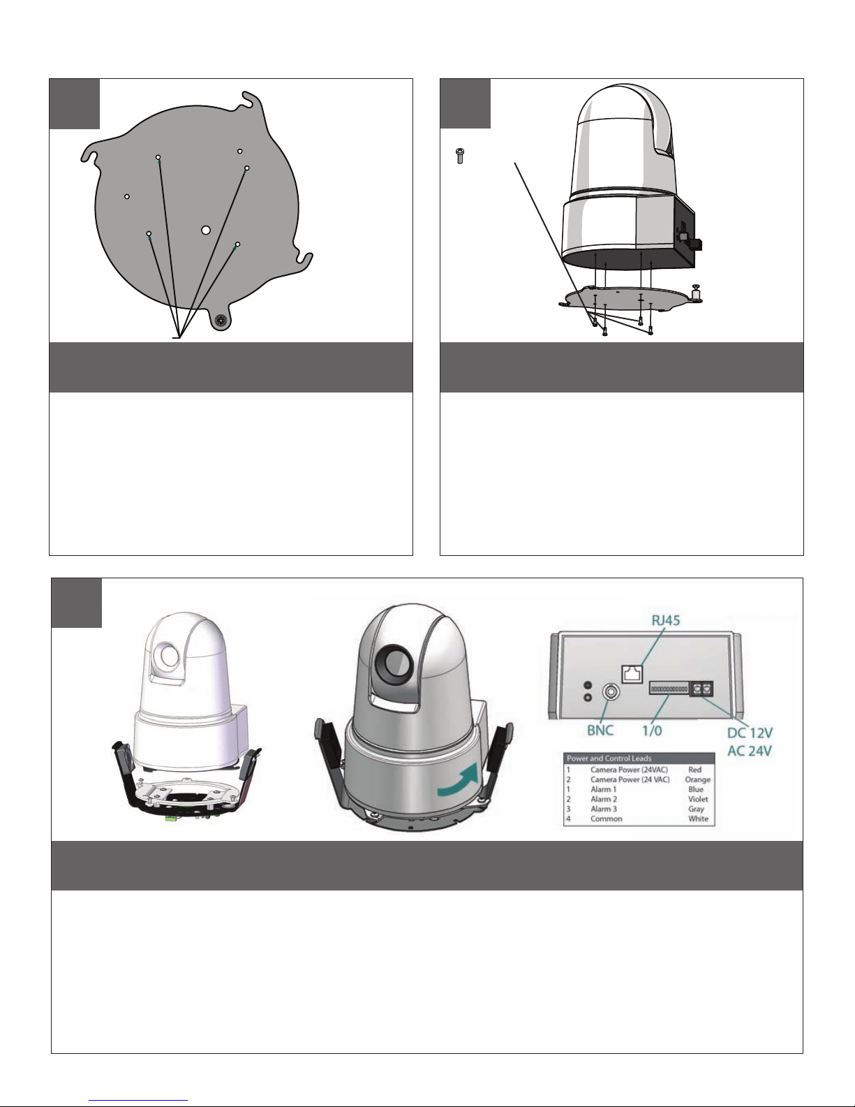
Camera Installation: SNC-RZ25
3
SNCRZ25
MOUNTING HOLES
Remove the quick release plate from the
housing.
• Quite la placa rápida del lanzamiento de la cubierta.
• Enlevez le plat rapide de dégagement du logement.
• Entfernen Sie die schnelle Freigabeplatte vom
Gehäuse.
• Remova a placa rápida da liberação da carcaça.
• Rimuova la piastra rapida del rilascio
4
(2) 3mm screws
(1) ¼”x 20 bolt
lock washer
SNCRZ25
Mount the camera to the plate using the
appropriate pattern.
• Monte la cámara fotográfica a la placa usando el
patrón apropiado.
• Montez l'appareil-photo au plat en utilisant le modèle
approprié.
• Bringen Sie die Kamera zur Platte mit dem passenden
Muster an.
• Monte a câmera à placa usando o teste padrão
apropriado.
• Monti la macchina fotografica alla piastra usando il
modello adatto.
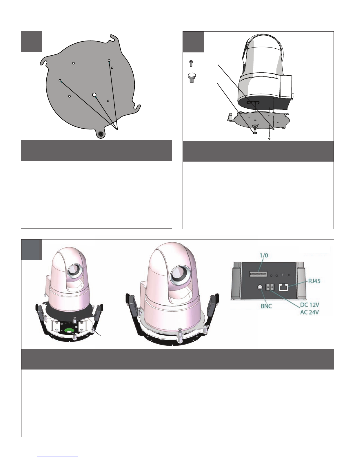
5
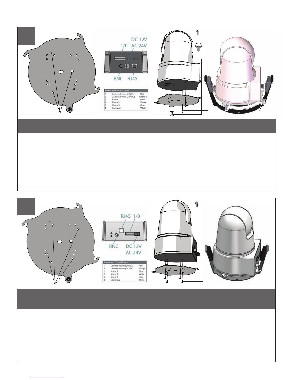
Camera Installation: SNC-RX530 / RX550 / RX570
6
SNCRX550
SNC RX550
MOUNTING HOLES
Remove the quick release plate from the
housing.
• Quite la placa rápida del lanzamiento de la cubierta.
• Enlevez le plat rapide de dégagement du logement.
• Entfernen Sie die schnelle Freigabeplatte vom
Gehäuse.
• Remova a placa rápida da liberação da carcaça.
• Rimuova la piastra rapida del rilascio
dall'alloggiamento.
7
(4) 3mm screws
SNCRX550
Mount the camera to the plate using the
appropriate pattern.
• Monte la cámara fotográfica a la placa usando el
patrón apropiado.
• Montez l'appareil-photo au plat en utilisant le
modèle approprié.
• Bringen Sie die Kamera zur Platte mit dem passenden Muster an.
• Monte a câmera à placa usando o teste padrão
apropriado.
• Monti la macchina fotografica alla piastra usando
il modello adatto.
8
Align tabs in mounting plate with the base plate and turn counterclockwise to secure.
NO SPACERS OR STANDOFFS REQUIRED.
• Alinee las pestañas en la placa de montaje con la placa base y girar en sentido antihorario para seguro. SPACERS O
NO OBLIGATORIO STANDOFFS.
• Alignez les onglets dans une plaque de montage avec la plaque de base et à assurer son tour dans le sens
antihoraire. SPACERS STANDOFFS OU NON REQUIS.
• Richten Sie Registerkarten in Montageplatte mit der Bodenplatte und dann gegen den Uhrzeigersinn zu sichern. NO
SPACERS ODER Standoffs REQUIRED.
• Alinhar guias na montagem da chapa com base prato e vire à esquerda para garantir. SPACERS OU NÃO
STANDOFFS REQUIRED.
• Allineare le linguette nella piastra di montaggio con la piastra di base e girare antiorario per sicurezza. DISTANZIALI
STANDOFFS N O RICHIESTE.
Camera Installation: SNC-RZ25 & SNC-RX SERIES in Wireless Ready Housing
SNC-RZ25
9
MOUNTING
PATTERN
Remove the quick release plate and mount it to the camera using the correct pattern, then add (4) 1/2” spacers, align
tabs on the mounting plate and turn counterclockwise to secure.
• Retire la placa y rápido montaje para la cámara utilizando el patrón, y luego añadir (4) 1 / 2 "de separación, se suman las pestañas
sobre la placa de montaje y gire en sentido antihorario para seguro.
• Retirez le plateau rapide et de le monter sur l'appareil en utilisant le modèle, puis ajouter (4) 1 / 2 "d'espacement, l'alignement des
onglets sur la plaque de montage et de tourner dans le sens antihoraire à garantir.
• Entfernen Sie die Schnellwechselplatte und montieren Sie ihn an der Kamera mit dem richtigen Muster, dann (4) 1 / 2 "
Zwischenstücken, Angleichung der Registerkarten auf der Montageplatte und dann gegen den Uhrzeigersinn zu sichern.
• Remova a placa liberação rápida e montá-lo para a câmera usando o padrão correto, em seguida acrescentar (4) 1 / 2 "
espaçadores, alinhar guias sobre a placa de montagem e vire à esquerda para garantir.
• Rimuovere la piastra a sgancio rapido e montare per la fotocamera utilizzando il modello corretto, quindi aggiungere (4) 1 / 2 "
distanziali, allineare le linguette sulla piastra di montaggio e girare antiorario per sicurezza.
(2) 3mm screws
(1) ¼”x 20 bolt
lock washer
1/2” Spacers
SNC-RX SERIES
10
MOUNTING
PATTERN
(4) 3mm screws
Remove the quick release plate and mount it to the camera using the correct pattern. Align
tabs on the mounting plate with the base plate screws and turn counterclockwise to secure.
NO SPACERS REQUIRED.
• Quite la placa rápida del lanzamiento y móntela a la cámara fotográfica usando el patrón correcto. Alinee las lengüetas en la placa de
montaje con los tornillos del embase y dé vuelta a la izquierda para asegurar.
• Enlevez le plat rapide de dégagement et montez-l'à l'appareil-photo en utilisant le modèle correct. Alignez les étiquettes du plat de support
avec les vis d'embase et tournez dans le sens contraire des aiguilles d'une montre pour fixer.
• Entfernen Sie die schnelle Freigabeplatte und bringen Sie sie zur Kamera mit dem korrekten Muster an. Richten Sie Vorsprünge auf der
Montageplatte mit den Grundplatteschrauben aus und drehen Sie nach links, um zu sichern.
• Remova a placa rápida da liberação e monte-a à câmera usando o teste padrão correto. Alinhe abas na placa de montagem com os
parafusos da placa baixa e gire-as no sentido anti-horário para fixar-se.
• Rimuova la piastra rapida del rilascio e montila alla macchina fotografica usando il modello corretto. Allinei le linguette sul giunto di supporto
con le viti della base di appoggio e giri in senso antiorario per fissare.
 Loading...