

Sony SMO-F551, SMO-F551-SD Technical Manual

SMO-F551
Magneto-Optical
Disk Drive
Version 1.1
Technical Guide and
Specifications

2 SMO-F551 Technical Guide and Specifications
Sony Corporation 1998
Safety Regulations
Owner's Record
The model and serial numbers are located on the top of the drive.
Record these numbers in the spaces provided below. Refer to them
whenever you call upon your sales representative regarding this
product.
Model No. SMO-F551 Serial No.
Information
You are cautioned that any changes or modifications not expressly
approved in this manual could void your authority to operate this
equipment.
Note: This equipment generates, uses and can radiate radio frequency
energy and may cause harmful interference to radio communications in
spite of a particular installation. However, there is no guarantee that
interference will not occur in a particular installation. If this equipment
dose cause harmful interference to radio or television reception, which
can be determined by turning the equipment off and on, the user is
encouraged to try correct the interference by one more of the following
measures:
• Reorient or relocate the receiving antenna.
• Increase the separation between the equipment and receiver.
• Connect the equipment into an outlet on a circuit different from
that to which the receiver is connected.
• Consult the dealer or an experienced radio/TV technician for
help.

SMO-F551 Technical Guide and Specifications 3
Sony Corporation 1998
WARNING
To prevent fire or shock hazard, do not expose the unit to
rain or moisture.
To avoid electrical shock, do not open the cabinet.
Refer servicing to qualified personnel only.
CAUTION
As the laser beam used in the SMO-F551
is harmful to the eyes, do not attempt to
disassemble the unit. Refer servicing to
qualified personnel only.
4 SMO-F551 Technical Guide and Specifications
Sony Corporation 1998
This label is affixed both on the top
cover and, internally, on the cartridge
tray of this unit.
LASER RADIATION WHEN OPEN. AVOID DIRECT EXPOSURE TO BEAM.
LASERSTRÅLING N Å R DEKSEL ÅPNES, UNNGÅ EKSPONERING FOR STRÅ LEN.
RADIATIONS DU LASER EN CAS D'OUVERTURE. EVITER TOUTE EXPOSITION DIRECTE AU FAISCEAU.
LASERSTRAHLUNG, WENN ABDECKUNG GEÖ FFNET. NICHIT DEM STRAHL AUSSETZEN.
LASERSTRÅLING V ED Å BING, UNDGÅ UDS/ ETTELSE FO R STRÅ LING.
ADVARSEL
DANGER
DANGER
VORSICHT
ADVARSEL
VARNING
VARO!
LASERSTRÅLING N Ä R DENNA DEL ÄR ÖPPNAD, STRÅ LEN Ä R FARLIG.
AVATTAESSA OLET ALTTIINA LASERSÄTEILYLLE, Ä L Ä KATSO SÄ TEESEN.
CLASS 1
LASER PRODUCT
LASER KLASSE 1
PRODUKT
4-631-572-01
This MO disk unit is classified as a
CLASS 1 LASER PRODUCT.
The CLASS 1 LASER PRODUCT
label is located at the top cover of
the unit.

SMO-F551 Technical Guide and Specifications 5
Sony Corporation 1998
Disclaimer
Version 1.1 (October, 1998)
Copyright © 1998 SONY Corporation. All Rights Reserved.
No part of this publication may be reproduced or transmitted in any form or by
any means graphic, electronic, electrical, mechanical or chemical, including
photocopying, recording in any medium, taping, by any computer, or information
storage and retrieval systems etc., without prior permission in writing from Sony.
While every effort has been made to ensure the accuracy of all information in
this document, Sony assumes no liability to any party for any loss or damage
caused by errors or omissions or by statements of any kind in the Sony
Technical Guide and Specifications, its updates, or special editions, whether
such errors are omissions or statements resulting from negligence, accident or
any other cause. Sony further assumes no liability arising out of the
application or use of any products or system described herein; nor any liability
for incidental or consequential damages arising from the use of this document.
Sony disclaims all warranties regarding the information contained herein,
whether expressed, implied or statutory, including implied warranties of
merchantability or fitness for a particular purpose.
Sony makes no representation that the interconnection of products in the
manner described herein will not infringe on existing or future patent rights, nor
do the descriptions contained herein imply the granting of license to make, use,
or sell equipment constructed in accordance with this description.
Sony reserves the right to make changes without further notice to any products
herein to improve reliability, function, or design.

6 SMO-F551 Technical Guide and Specifications
Sony Corporation 1998
References
• SMO-F551 SCSI Specifications
• ANSI-X3.131-1994: Small Computer System Interface-2 (SCSI-2)
• ISO/IEC 15286 (final draft) : Information Technology - 130 mm Optical Disk
Cartridges - Capacity: 5.2 Gbytes per Cartridge - For Information Interchange
• ISO/IEC 14517-1997 : Information Technology - 130 mm Optical Disk
Cartridges - Capacity: 2.6 Gbytes per Cartridge - For Information Interchange
• ISO/IEC 13549-1994 : Data Interchange on 130 mm Optical Disk Cartridges
- Capacity: 1.3 Gbytes per Cartridge -
• ISO/IEC 10089-1991 Format A : 130 mm rewritable Optical Disk Cartridges for
Information Interchange.
• ISO/IEC 11560-1992 : 130 mm Write Once Optical Disk Cartridges for
Information Interchange - Capacity 650Mega-bytes per Cartridge -
Printing History
November 25, 1997 Preliminary Version 1.0
March 10, 1998 Version 1.0
October 1, 1998 Version 1.1

SMO-F551 Technical Guide and Specifications 7
Sony Corporation 1998
CONTENTS
Using This Guide................................................................................................................... 9
Chapter 1. INTRODUCTION................................................................................................. 10
Product Brief...............................................................................................................10
Compatible Media.......................................................................................................11
System Configuration ..................................................................................................12
Location and Function of Parts ....................................................................................12
Front Panel....................................................................................................... 12
Rear Panel........................................................................................................13
Top Panel .........................................................................................................14
Chapter 2. INSTALLATION...................................................................................................15
Component and Accessory Check List ........................................................................ 15
Installation Requirements ............................................................................................15
Location Requirements .....................................................................................15
Cooling Requirements.......................................................................................16
Temperature Alarm...........................................................................................16
Functional Switch Settings.......................................................................................... 17
SCSI and DC Power Connector...................................................................................21
SCSI Terminator.........................................................................................................22
Optional Switch Setting...............................................................................................23
Chapter 3. PRECAUTIONS...................................................................................................25
Drive Handling Precautions .........................................................................................25
Disk Handling Precautions ..........................................................................................25
Notes on Cleaning.......................................................................................................26
Cleaning the Drive Unit .....................................................................................26
Cleaning the Disks.............................................................................................26
Chapter 4. SPECIFICATIONS...............................................................................................27
Drive Specifications.................................................................................................... 27
Media Related Characteristics...........................................................................27
Drive Specifications...........................................................................................31
Chapter 5. SYSTEM CONFIGURATION............................................................................... 35
Optical Head ..........................................................................................................35
Laser Diode Driver.................................................................................................35
Data Separation Block ...........................................................................................35
Bias Magnet Block.................................................................................................35
Loading Block........................................................................................................35
Microprocessor ......................................................................................................36
DSP/Servo Blocks .................................................................................................37
Integrated Optical Controller Block.........................................................................37
Buffer Memory.......................................................................................................38
Chapter 6. HOST INTERFACE.............................................................................................. 39
Data Bus and Signal Lines.......................................................................................... 39
Control Method and Procedures..................................................................................42
Command Summary...................................................................................................43
Chapter 7. BUSY INDICATOR ..............................................................................................45
Flashing Pattern and Drive's Internal Condition...........................................................45

8 SMO-F551 Technical Guide and Specifications
Sony Corporation 1998
Appendix
1. Mechanical Dimension (Overview)
2. Mechanical Dimension (Front View)
3. Mechanical Dimension (Side View)
4. Mechanical Dimension (Bottom View)
5. Mechanical Dimension (Rear View)
6. Mechanical Dimension (Mounting)
7. Mechanical Dimension (Packaging)
8. Mechanical Dimension (Packaging)

SMO-F551 Technical Guide and Specifications 9
Sony Corporation 1995
Using This Guide
This guide contains information on Sony SMO-F551 Magneto-Optical Disk Drive.
This guide is divided into the following sections.
n
Chapter 1. INTRODUCTION
This chapter provides a general overview of the drive, touching upon its features.
n
Chapter 2. INSTALLATION
This chapter explains how to set the functions and SCSI ID address.
n
Chapter 3. PRECAUTIONS
This chapter lists precautions regarding the operation of the drive and the disk
cartridges. It also explains the proper cleaning method of the disk cartridges.
n
Chapter 4. SPECIFICATIONS
This chapter provides performance data, environmental, electrical, and physical
specifications.
n
Chapter 5. SYSTEM CONFIGURATION
This chapter contains detailed descriptions on the drive's subassemblies.
n
Chapter 6. HOST INTERFACE
This chapter provides information on the host interface signal lines, diagnostics and
SCSI command summary.
n
Chapter 7. BUSY INDICATOR
This chapter provides information on the BUSY indicator notification.
n
APPENDIX
The appendix contains mechanical dimensions.

10 SMO-F551 Technical Guide and Specifications
Sony Corporation 1998
Chapter 1. INTRODUCTION
Product Brief
The Sony SMO-F551 is a 5.2 Gbytes 5 1/4 inch (130mm) multi-function optical disk
drive in a half height form factor. It is compatible with ISO standard 5.2 Gbytes
optical disk cartridge. The drive also maintains backward compatibility with ISO 2.6
Gbytes, 1.3 Gbytes and 650 Mbytes cartridges. Write-Once type media can be used
as well as rewritable media. The related international standards are listed below.
ISO/IEC 15286 (final draft) 5.2GB/4.8GB/4.1GB Rewritable and Write-Once
Cartridge
ISO/IEC 14517 -1997 2.6GB/2.3GB Rewritable and Write-Once Cartridge
ISO/IEC 13549 -1994 1.3GB/1.2GB Rewritable and Write-Once Cartridge
ISO/IEC 10089 -1991 650MB/594MB Rewritable Cartridge (Format A)
ISO/IEC 11560 -1992 650MB/594MB Write-Once Cartridge
High power 685 nm wave length laser diode, mark edge recording technology and Run
Length Limited coding known as RLL(1,7) achieve 5.2 Gbytes capacity within the 5 1/4
inch form factor.
Fig. 1.1 : SMO-F551 MO Disk Drive
SMO-F551 Technical Guide and Specifications 11
Sony Corporation 1998
The drive spins the media at 3,300 min-1 (rpm). This provides sustained read
transfer rates of up to 5.07 MB/s with 5.2 Gbytes media.
The drive is attached to the host computer through its single ended SCSI-2 interface.
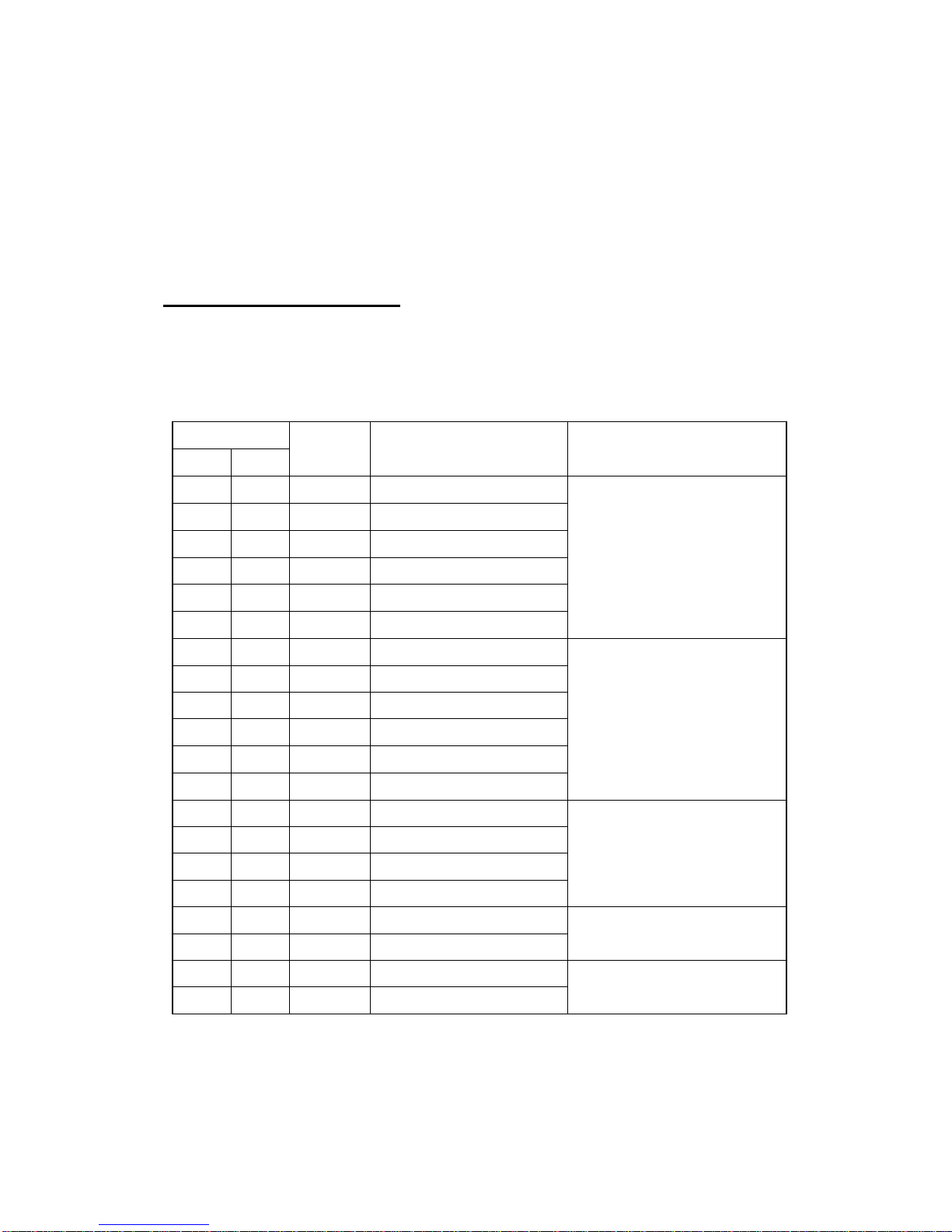
Compatible Media
SMO-F551 is compatible with the following 5 1/4 inch (130 mm) Magneto Optical Disks.
Compatibility
Read Write
Type Description ISO Standard
o o 8X R/W 5.2GB 2048 bytes/sector
o o 8X R/W 4.8GB 1024 bytes/sector
o o 8X R/W 4.1GB 512 bytes/sector
o o 8X WO 5.2GB 2048 bytes/sector
o o 8X WO 4.8GB 1024 bytes/sector
o o 8X WO 4.1GB 512 bytes/sector
ISO/IEC 15286 (final draft)
o o 4X R/W 2.6GB 1024 bytes/sector ISO/IEC 14517
o o 4X R/W 2.3GB 512 bytes/sector
o o 4X WO 2.6GB 1024 bytes/sector
o o 4X WO 2.3GB 512 bytes/sector
o o 4X DOW 2.6GB 1024 bytes/sector
o o 4X DOW 2.3GB 512 bytes/sector
o x 2X R/W 1.3GB 1024 bytes/sector ISO/IEC 13549
o x 2X R/W 1.2GB 512 bytes/sector
o x 2X WO 1.3GB 1024 bytes/sector
o x 2X WO 1.2GB 512 bytes/sector
o x 1X R/W 650MB 1024 bytes/sector ISO/IEC 10089
o x 1X R/W 594MB 512 bytes/sector
o x 1X WO 650MB 1024 bytes/sector ISO/IEC 11560
o x 1X WO 594MB 512 bytes/sector
W/R : Rewritable, WO : Write-Once, DOW : Direct Overwrite
12 SMO-F551 Technical Guide and Specifications
Sony Corporation 1998
System Configuration
SMO-F551 is connected to a host computer through its SCSI interface. The maximum of
seven peripheral devices can be linked as a daisy chain on the SCSI bus.
Host Computer
SCSI Cable
SMO-F551
SCSI peripheral devices
Fig. 1.2 : System Configuration Example
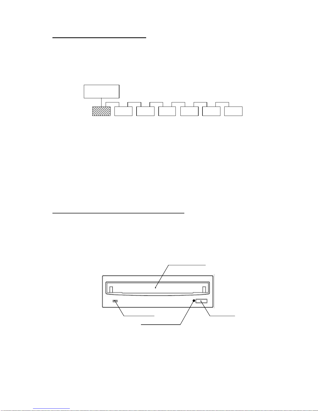
Location and Function of Parts
This section provides a general description of the SMO-F551 Magneto-Optical disk drive.
Front Panel
BUSY Indicator
Emergency Eject Hole
Disk Insertion Slot
Eject Button
Fig. 1.3 : Front View
n
Disk Insertion Slot
Insert the disk cartridge into this slot.
SMO-F551 Technical Guide and Specifications 13
Sony Corporation 1998
n
BUSY Indicator
The indicator turns from green to amber while the drive is reading or writing data. Do not
eject the disk cartridge when this indicator is amber. Refer to Chapter 7. BUSY
INDICATOR.
n
Emergency Eject Hole
If a disk cartridge cannot be ejected using the eject button or SCSI command, turn off the
power and insert the emergency eject tool(sold separately) or other similar object, such as
a straightened paper clip into the emergency eject hole.
n
Eject Button
Press this button to eject the disk cartridge from the drive. The drive suspends the
ejection of disk cartridge while executing a SCSI command or while holding data to be
flushed from its cache buffer.
Manual eject by this eject button can be disabled by the functional switch or software
settings.
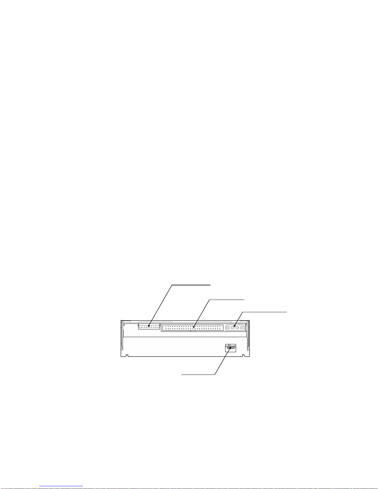
Rear Panel
Functional Switch
SCSI Connector
DC Power Connector
GND Terminal
Fig. 1.4 : Rear View
n
Functional Switch
A 24 pin header socket jumper block is used for setting the SCSI ID and other drive
configurations. Refer to section "Functional Switch Settings" for more information.

14 SMO-F551 Technical Guide and Specifications
Sony Corporation 1998
n
SCSI and DC Power Connector
A combination 50-pin SCSI and 4-pin power connector is used to connect a standard SCSI
cable as well as +12V and +5V power line. Refer to Chapter 2., "SCSI and DC Power
Connector" section for more information.
n
GND Terminal
This is the ground terminal of the drive.
Top Panel
Optional Switch
ON
OFF
1 2 3 4 5 6 7 8
1 2 3 4 5 6 7 8
ON
OFF
S501
S502
(
Rear End of the Drive
)
Fig. 1.5 : Top view
n
Optional Switches (S501, S502)
These two dip switches allow the user to set drive configuration. Refer to Chapter 2.,
"Optional Switch Setting" section.
 Loading...