

Sony SLV-UY, SLV-E220AE, SLV-VP1, SLV-VP2, SLV-E270CP Service Manual
...
MICROFILM
SERVICE
MANUAL
J VIDEO CASSETTE RECORDER
Photo : SLV-E280UX
AEP Model
SLV-E120AE/E220AE/VP1/VP2/E270CP/VC1/VC2/E280CP/VC1/VC2
UK Model
SLV-E220UY/E280UX
SPECIFICATIONS
System (SLV-E220UY/E280UX)
Channel coverage
PAL (I) :
UHF B21 - B69
RF output signal
UHF I21 - 69 CH
Aerial out
75-ohm asymmetrical aerial socket
System (EXCEPT SLV-E220UY/E280UX)
Channel coverage
PAL (B, G) :
VHF E2 - E12
(comprese channel C)
(A - H only For Italy)
UHF E21 - E69
CATV S01 - S03, S1 - S20
HYPER BAND S21 - S41
Intermediate frequency
F1 - 1 Video 38.9MHz
F2 - 1 Audio 33.4MHz
RF output signal
UHF G22 - 69
Aerial out
75-ohm asymmetrical aerial socket
Inputs/outputs
ÚEURO-AV1
21-pin
Video input : pin 20
Audio input : pins 2 and 6
Video output : pin 19
Audio output : pins 1 and 3
J EURO-AV2 (2nd Scart)
21-pin
(Except SLV-E120AE/E220 Series)
Video input : pin 20
Audio input : pins 2 and 6
Front Line In (SLV-E280 Series)
VIDEO IN, Phono jack (1)
Input signal : 0.5 –1.5 Vp-p
75 ohms, unbalanced, sync negative
AUDIO IN, Phone jack (1)
Input level : –8 dBs
(0 dBs = 0.755 Vrms)
Input impedance : more than
47 kilohoms
General
Power requirements
220 – 240 V AC, 50 Hz
Power consumption
17 W
5W (standby)(SLV-E120AE/E220 Series)
6W (standby)(Except SLV-E120AE/E220 Series)
Operating temperature
5°C to 40°C
Storage temperature
–20°C to 60°C
Dimensions
Approx. 360 x 97 x 298 mm (w/h/d)
including projecting parts and controls
Mass
Approx. 3.7 kg
Supplied accessories
Remote commander (1)
R6 (size AA) batteries (2)
Aerial cable (1)
Mains lead (1)
Design and specifications are subject to change without notice.
SLV-E120AE/E220AE/UY/VP1/VP2/E270CP/VC1/VC2/
E280CP/UX/VC1/VC2
RMT-V206C/V206D/V207C/V207D/V207E/V207G/V207H

– 2 –
SAFETY-RELATED COMPONENT WARNING!!
COMPONENTS IDENTIFIED BY MARK ! OR DOTTED
LINE WITH MARK ! ON THE SCHEMA TIC DIA GRAMS AND
IN THE P ARTS LIST ARE CRITICAL TO SAFE OPERATION.
REPLACE THESE COMPONENTS WITH SONY PARTS
WHOSE PART NUMBERS APPEAR AS SHOWN IN THIS
MANUAL OR IN SUPPLEMENTS PUBLISHED BY SONY.
SAFETY CHECK-OUT
After correcting the original service problem, perform the following
safety check before releasing the set to the customer :
4. Look for parts which, though functioning, show obvious
signs of deterioration. Point them out to the customer and
recommend their replacement.
5. Check the B+ voltage to see it is at the values specified.
1. Check the area of your repair for unsoldered or poorly-soldered connections. Check the entire board surface for solder splashes and bridges.
2. Check the interboard wiring to ensure that no wires are
“pinched” or contact high-wattage resistors.
3. Look for unauthorized replacement parts, particularly transistors, that were installed during a previous repair. Point
them out to the customer and recommend their replacement.

– 3 –
1. GENERAL
Step 1 Setting up the remote commander ..................... 1-1
Step 2 Connecting the VCR .......................................... 1-1
Step 3 Tuning the TV to your VCR............................... 1-1
Step 4 Selecting a language........................................... 1-2
Step 5 Tuning the VCR to TV Channels ....................... 1-2
Step 6 Setting the Clock ................................................ 1-2
Additional Tuning Instructions ..................................... 1-3
Setting a Satellite Tuner ................................................ 1-3
Playing a Tape ............................................................... 1-3
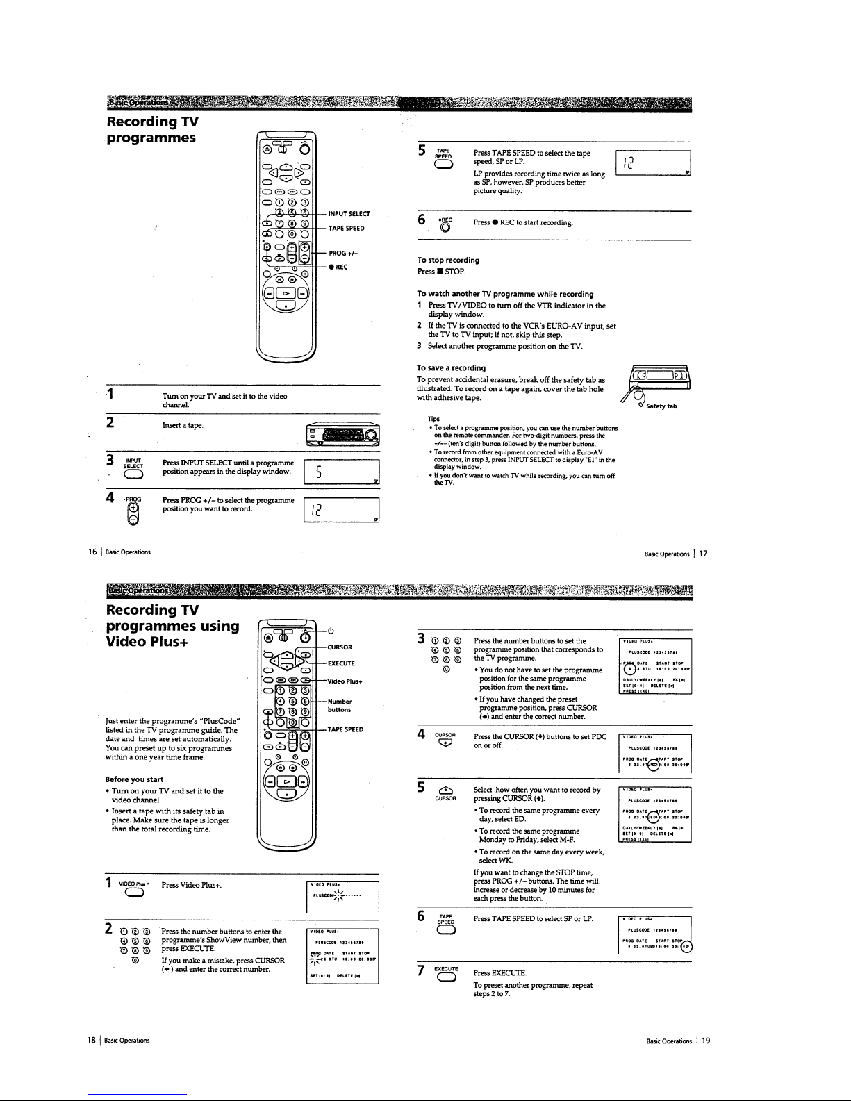
Recording TV Programmes........................................... 1-4
Recording TV Programmes using Video Plus + ........... 1-4
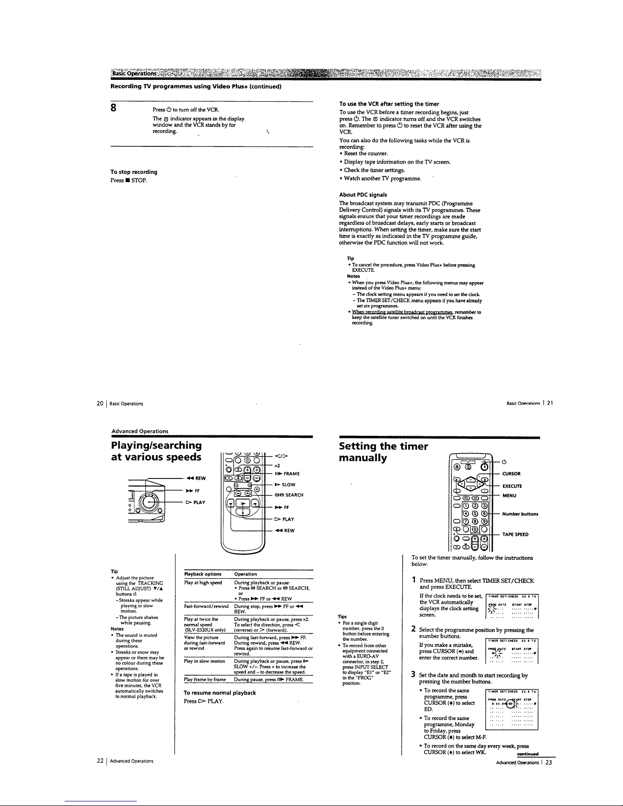
Playing/Searching at Various Speeds ............................ 1-5
Setting the Timer Manually........................................... 1-5
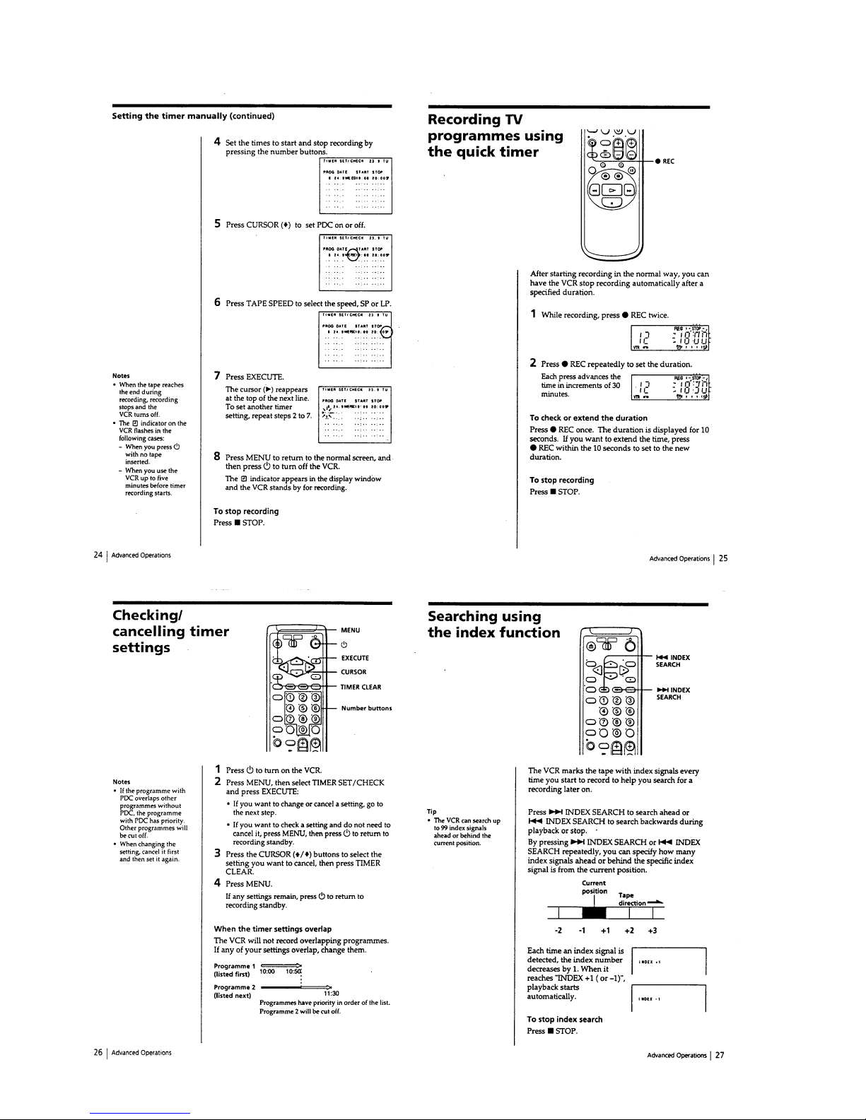
Recording TV Programmes using the Quick Timer...... 1-6
Checking/Cancelling Timer Settings............................. 1-6
Searching using the index function ............................... 1-6
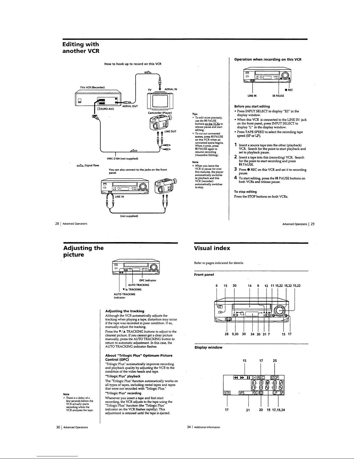
Editing with another VCR............................................. 1-7E
Adjusting the Picture..................................................... 1-7E
Visual index................................................................... 1-7E
2. DISASSEMBLY
1-1. Removal of Cabinet, Mechanism Unit and Main
Board ..................................................................... 2-1
Removing the Cabinet Parts .................................. 2-1
Removing the Mechanism Main Unit and the
CP-1 PWB Assembly............................................. 2-1
l-2. Temporarily Setting Up and Connecting
CP-1 PWB Assembly............................................. 2-3E
1-3. Installation of the Front Panel................................ 2-3E
3. DIAGRAMS
Circuit Boards Location ................................................ 3-1
Overall wiring Diagram ................................................ 3-3
Mechanism Connection Diagram.................................. 3-5
Video Circuit Diagram .................................................. 3-6
System Control & Servo Circuit Diagram ................... 3-9
Audio Circuit Diagram.................................................. 3-12
Terminal & Input/ Output Selector Circuit Diagram
(SLV-E270 & E280 Series) ........................................... 3-14E
4. SCHEMATIC DIAGRAMS AND PRINTED
WIRING BOARDS
CP-1 Board (PW-A) Power Supply Circuit Diagram .... 4-1
CP-1 Board (AD-A) Terminal & Selector
(SLV-E270 & E280 Series) ........................................... 4-3
CP-1 Board (AD-A) Terminal Circuit Diagram
(SLV-E120AE/E220 Series).......................................... 4-5
CP-1 Board (VA-A) Video & Audio Circuit Diagram
(SLV-E270 Series/E280CP/VC1/VC2)......................... 4-7
CP-1 Board (VA-A) Video & Audio Circuit Diagram
(SLV-E120AE & E220 Series)...................................... 4-9
CP-1 Board (VA-A) Video & Audio Circuit Diagram
(SLV-E280UX).............................................................. 4-11
Video Circuit Waveforms.............................................. 4-13
VP-1 Board Video Pre-Amp circuit Diagram ............... 4-14
CP-1 Board (SV-A) Servo Circuit Diagram.................. 4-16
Servo Circuit Waveforms .............................................. 4-18
CP-1 Board (SY-A) System Control, Timer & Tuner
Circuit Diagram (Except SLV-E220UY/E280UX) ....... 4-19
IC 301 System Control, Timer & Tuning Control MPU Pin
Functions Ta ble ............................................................. 4-20
CP-1 Board (SY-A) System Control, Timer & Tuner
Circuit Diagram (SLV-E220UY/E280UX) ................... 4-21
TM-1 Board Operation Key Circuit Diagram ............... 4-27
TABLE OF CONTENTS
Section Title Page
______ ____ ____
Section Title Page
______ ____ ____
TM-2 Board Circuit Diagram........................................ 4-29
A7101 Display (FLD) Grid/Anode Assignment
Drawing & Table ........................................................... 4-30
TM-9 Board PDC/VPS (SLV-E220VP1/E270 &
E280 Series) .................................................................. 4-31E
5. ADJUSTMENTS
1. Maintaining and Checking the Mechanism............... 5-1
l -1. Regular Checks and Maintenance Items............... 5-1
1-1-1. Regular Checks................................................ 5-1
1-1-2. Cleaning............................................................ 5-1
1-2 Service Tools ........................................................... 5-2
1-2-1. Service Tools ................................................... 5-2
1-2-2. Using the Relay Cable (VHJ-0106).................. 5-3
2. An Overview of the Mechanism ................................ 5-3
2-1. Names of the Main Parts........................................ 5-3
2-1-1. Cassette Mechanism Assembly ........................ 5-3
2-1-2. Top View .......................................................... 5-4
2-1-3. Under Side ........................................................ 5-4
2-2. An Overview of the Mechanism Modes ................ 5-5
2-2-1. Mechanism Mode Switching Table .................. 5-5
2-2-2. Movement Check List for the Main Parts of the
Mechanism........................................................ 5-6
2-2-3. How to Check the Mechanism
Mode Position................................................... 5-6
2-2-4. Self-Diagnosis Display ..................................... 5-6
3. Disassembling the Main Parts of the Mechanism ..... 5-7
3-1. How to Make the Mechanism Move...................... 5-7
3-1-1. How to Operate the Loading Motor Using
A DC Voltage Supply ....................................... 5-7
3-1-2. Operating the Loading Motor
by the Manual Method...................................... 5-7
3-1-3. Making the Mechanism Move
Using the Manual Method ................................ 5-7
3-2. Mechanism Unit..................................................... 5-8
3-3. Cassette Drive Mechanism..................................... 5-8
3-3-1. Cassette Mechanism Assembly ........................ 5-8
3-3-2. Cassette Drive Gear .......................................... 5-9
3-3-3. Door opener, Under Frame and Stand L........... 5-9
3-3-4. Start Rack Gear and Front Rack Gear .............. 5-10
3-4. Cleaner Roller Assembly ....................................... 5-10
3-5. Cylinder (DRUM).................................................. 5-11
3-5-1. Upper Cylinder Assembly (UPPER DRUM) ... 5-11
3-5-2. Cylinder Motor (ROTOR and STATOR) .......... 5-12
3-5-3. Cylinder Assembly ........................................... 5-12
3-6. FE Head and ACE Head......................................... 5-13
3-6-1. Audio R/P Head Assembly (ACE HEAD)........ 5-13
3-6-2. Full Erase Head ................................................ 5-13
3-7. Capstan Motor........................................................ 5-14
3-7-1. Capstan Motor .................................................. 5-14
3-7-2. Capstan Brake Assembly.................................. 5-14
3-8. Loading Motor Assembly and
Worm Gear Assembly............................................ 5-15
3-9. Pinch Roller Pressure Mechanism ......................... 5-15
3-9-1. Pinch Roller Lever Assembly ........................... 5-15
3-9-2. Pinch Lift Cam and Pinch Cam Gear ............... 5-16
3-10. L Guide Lever Assembly and
Load Lever Assembly .......................................... 5-17
3-11. BT Lever Assembly ............................................. 5-17
3-12. Reel Drive Mechanism......................................... 5-18
3-12-1. Reel belt, Reel Pulley, Friction Gear
Assembly and Clutch Change Lever............... 5-18
3-12-2. Clutch Mounting Assembly............................ 5-18
3-12-3. S Soft Lever, Supply Reel Assembly
and S Reel Gear .............................................. 5-18

– 4 –
Section Title Page
______ ____ ____
3-12-4. T Soft Brake Assembly, Take Up Reel
Assembly, T Reel Gear ................................... 5-19
3-13. Brakes .................................................................. 5-19
3-13-1. S Brake Assembly, T Brake
Assembly, T Brake ACT Slide ........................ 5-19
3-13-2. Brake Control Lever and Brake ACT Lever
Assembly ........................................................ 5-20
3-13-3. S Brake ACT Slide and BT Spring Lever
Assembly ........................................................ 5-20
3-14. Guides .................................................................. 5-21
3-14-1. Guide Roller Assembly................................... 5-21
3-14-2. S and T Incline Mounting Assemblies............ 5-21
3-15. Wheel Gear 2, Main Cam and Mode Switch ....... 5-22
3-16. Crescent Slide ...................................................... 5-23
3-17. S Load Gear, T Load Gear, S Load Lever
Assembly and T Load Lever Assembly ............... 5-24
3-18. Tape Sensors, Reel Sensor and EP SW Lever...... 5-25
3-18-1. Tape Top Sensor and Tape End Sensor ........... 5-25
3-18-2. Reel Sensor ..................................................... 5-25
3-18-3. EP Switch Lever ............................................. 5-25
4. Mechanism Checks and Adjustments........................ 5-26
4-1. Reel Table Torque Check ....................................... 5-26
4-2. Adjusting the BT Lever Assembly Position and
Checking the Back Tension Torque in Play Mode. 5-26
4-2-1. BT Lever Pole Position Adjustment ................. 5-26
4-2-2. Checking the Back Tension Torque
Play Mode......................................................... 5-26
4-3. Tape Path Adjustment ............................................ 5-27
4-3-1. Adjustment Procedure ...................................... 5-27
4-3-2. Load Lever Assembly Height Adjustment........ 5-27
4-3-3. Guide Roller Height Adjustment...................... 5-28
4-3-4. Audio R/P Head (ACE HEAD) Height
Adjustment, Azimuth Adjustment and
Horizontal Position Adjustment........................ 5-29
4-3-5. Checking After Adjustment .............................. 5-30E
6. ELECTRICAL ADJUSTMENTS
Circuit Boards Location ................................................ 6-1
Self -Diagnosis Display................................................. 6-2
1. Self-Diagnosis Contents and Mechanism Mode
Display ...................................................................... 6-2
2. Electrical Adjustment ................................................ 6-4
2-1. Servo Circuit Adjustment....................................... 6-4
2-1-1. Test Equipment and Standards Required .......... 6-4
2-1-2. Location of Adjustment Points ......................... 6-4
2-1-3. Switching Position Adjustment ........................ 6-5
2-2. Video Circuit Relay Jig .......................................... 6-6
2-2-1. Test Equipment and Standards Required .......... 6-6
2-3. IF Circuit Adjustment ............................................ 6-7E
2-3-1. Test Equipment and Standard Required ........... 6-7E
2-3-2. Location of Adjustment Point........................... 6-7E
2-3-3. RF AGC Adjustment........................................ 6-7E
3. Test Points for Tape Path Adjustment ....................... 6-7E
7. EXPLODED VIEWS
7-1. Cabinet & Chassis Parts......................................... 7-1
7-2. Mechanism Parts-1 ................................................ 7-3
7-3. Mechanism Parts-2................................................. 7-5E
8. ELECTRICAL PARTS LIST ................................. 8-1
Hardware List................................................................ 8-10E
1-1
SECTION 1
GENERAL
This section is extracted from
SLV-E280UX instruction manual.
SLV-E120AE/E220AE/UY/VP1/VP2/E270CP/VC1/VC2/E280CP/UX/VC1/VC2
1-2
1-3
1-4
1-5
1-6
1-7 E
2-1
SECTION 2
DISASSEMBLY
1-1. REMOVAL OF CABINET, MECHANISM UNIT, AND MAIN BOARD
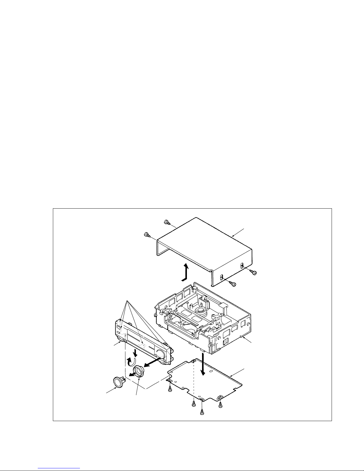
REMOVING THE CABINET PARTS (Fig. 1-1-1 )
1. Remove the cabinet and bottom cover by removing the
four screws 1 and four screws 2 .
2. Pull out the shuttle knob by fingers together with the
button assembly, and remove the front panel by removing the locks of the clamps (A) using a screwdriver. etc.,
and slightly rotating the bottom part in the direction of
the arrow.
Notes: • Electrical adjustments for the this model can be
performed with only the cabinet removed.
• When replacing the bottom cover, do not tighten
the screws 2 too much. Excess tightness may
damage the screw taps on the chassis.
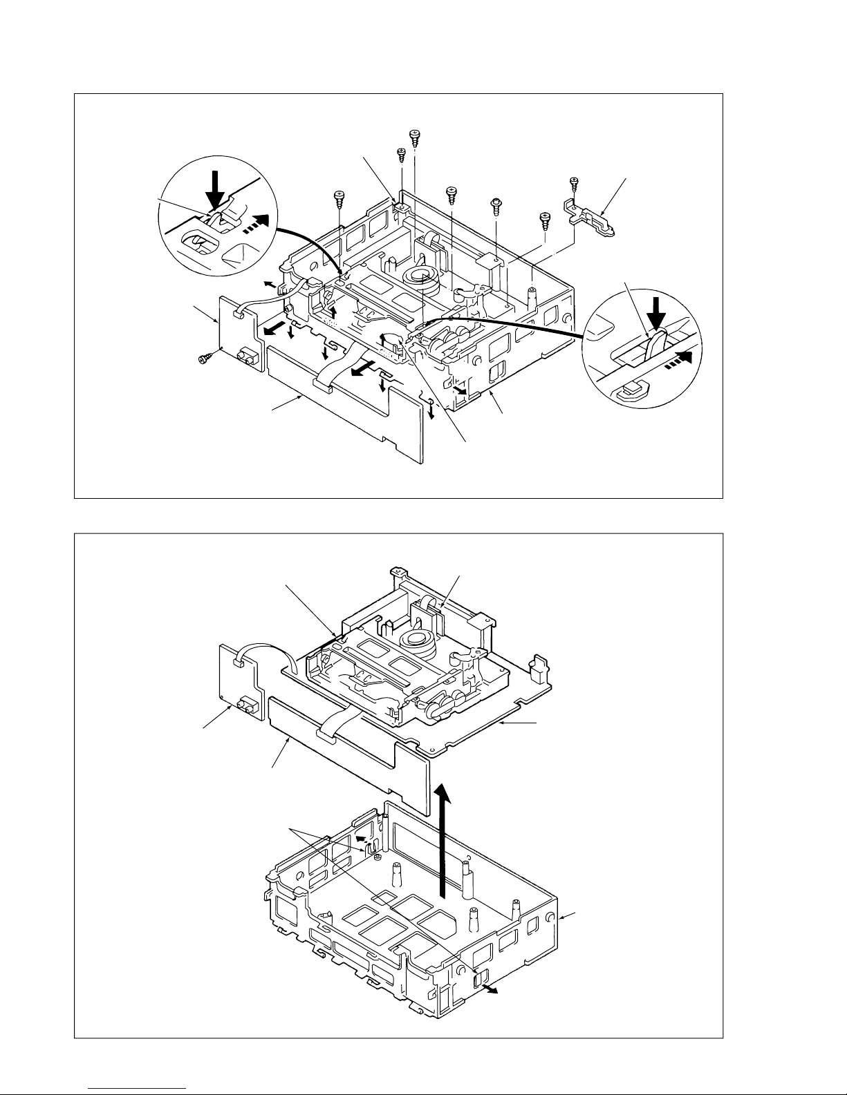
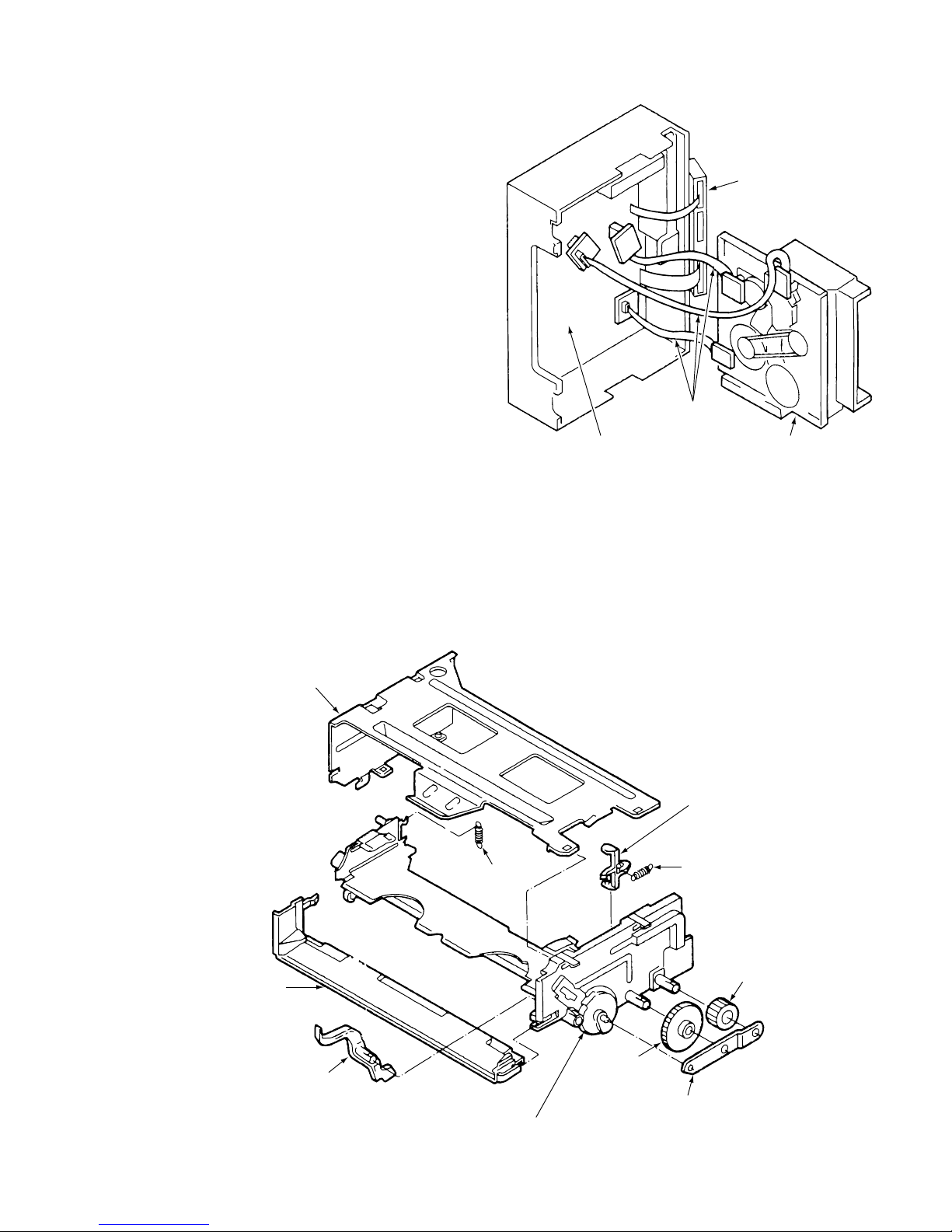
REMOVING THE MECHANISM MAIN UNIT AND
THE CP-1 PWB ASSEMBLV (Fig.1-1-2 and 1-1-3)
After removing the cabinet parts, remove the mechanism
unit and the CP-1 PWB assembly connected as follows.
1. First, remove the red screw 3 of the TB-1 PWB, spread
out lock clamps (B) and (C) in the arrow direction
slightly and remove TM-1 PWB and TM-2 PWB as
shown in Fig. 1-1-2.
2. Remove the screw 4 at the back of the chassis.
3. Remove the red screw 5 in the chassis, remove the red
screw 6, and remove the holder in this order.
4. Remove the two screws 7 and two screws 8 of the
mechanism unit. The two screws 8 of the cassette tray
can be removed easily by pushing the tray lock lever in
the arrow direction to remove the lock as shown in the
enlarge view A and by pushing the lid opener lever in
the arrow direction to remove the lock as shown in the
enlarge view B.
5. Lift up the whole mechanism unit and main board (CP-1
PWB assembly), and as shown in Fig. 1-1-3. push the
two lock clamps (D) of the chassis i n the arrow direction so that they can be removed from the chassis.
1
1
1
1
2
2
2
2
Clamps (A)
Front Panel
Button Assembly
Shuttle Knob
Main Unit
Bottom Cover
Cabinet
Fig. 1-1-1
SLV-E120AE/E220AE/UY/VP1/VP2/E270CP/VC1/VC2/E280CP/UX/VC1/VC2
2-2
3
8
5
7
8
4
7
6
Cassette Tray
Chassis
Lid Opener Lever
Holder
Terminal Board
(B)
(B)
(C)
(C)
(C)
(C)
(C)
(C)
Tray Lock Lever
TM-1 PWB
TM-2 PWB
Fig. 1-1-2
A
B
Chassis
TM-1 PWB
TM-2 PWB
VP-1 PWB Assembly
Mechanism Main Unit
Clamps (D)
CP-1 PWB Assembly
Fig. 1-1-3
2-3
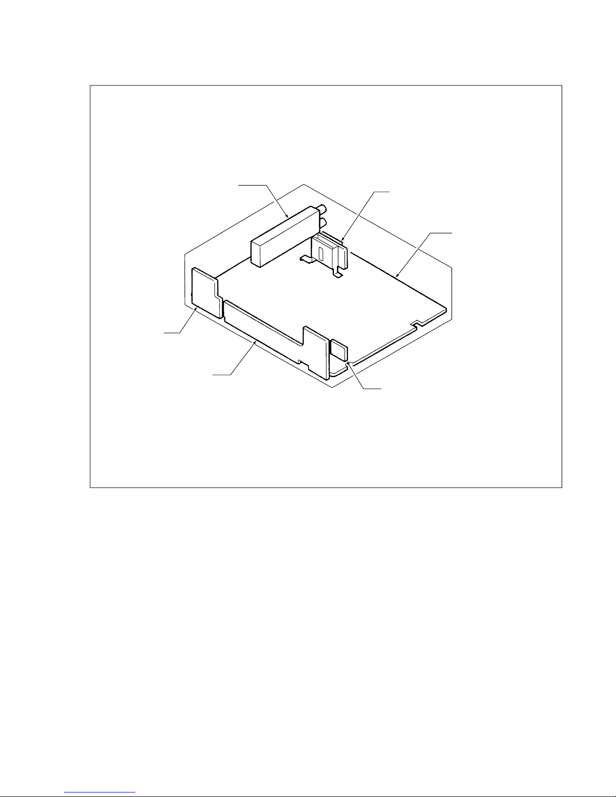
1-2. TEMPORARILY SETTING UP AND CONNECTING CP-1 PWB ASSEMBLY
The following is an example of how to place and connect the main board without a jig, when repairing the CP-1 PWB
assembly.
1. Place the mechanism unit and main board up side down
as a whole on a flat surface with the foil side of the main
board facing up.
2. Operate the unit using the buttons on TM-1 PWB or the
remote control.
Mechanism Main Unit
Screws
9
CP-1 PWB Assembly (Foil side)
Terminal Board
Cassette Compartment
TM-1 PWB
TM-2 PWB
Fig. 1-1-4
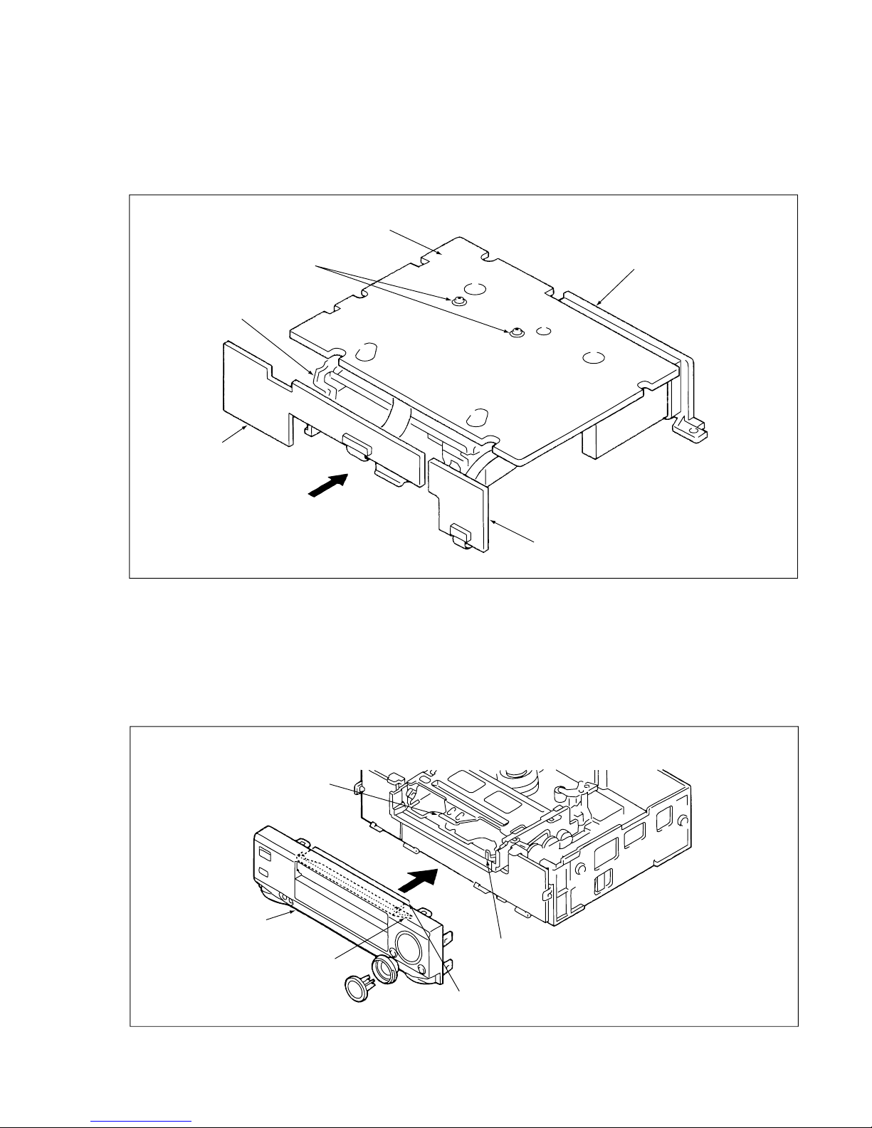
1-3. INSTALLATION OF THE FRONT PANEL
When installing the front panel to the chassis after repaires and adjustments.
1.Pressing down the door opener lever of the mechanism
main unit.
2. Set the cassette door to half-opened state as shown in
Fig. 1-1-5, and install the front panel to the chassis.
Note: Opened cassette door position does not install the
front panel to the chassis.
Jutted part of
Cassette Holder
Cassette Door
(Position A)
Cassette Door
(Position B)
Door Opener Lever
Front Panel
Fig. 1-1-5
E
3-1
SECTION 3
DIAGRAMS
CIRCUIT BOARDS LOCATION
CP-1 PWB Assembly
VP-1 PWB Assembly
3 in 1 Tuner
(Tuner / RF Conv.)
TM-1 PWB
TM-9 PWB
TM-2 PWB
SLV-E120AE/E220AE/UY/VP1/VP2/E270CP/VC1/VC2/E280CP/UX/VC1/VC2
5-1
1-1. REGULAR CHECKS AND
MAINTENANCE ITEMS
To obtain full function and maximum performance from
the set, and to stop it getting dirty or scratched, we
recommend that you carry out the following maintenance
procedures and regular checks. The maintenance checks
described in the following section should also be carried
out without fail after carrying out any repairs to the set.
1-1-1. REGULAR CHECKS
1. MAINTAINING AND CHECKING THE MECHANISM
NOTE: OIL AND GREASE
• Always use the specified brands of oil and grease. If you
use a grease with the wrong viscosity, for example, this
can lead to all sorts of problems. Be careful to keep the
oil and grease free of dust and foreign bodies.
• A “drop” of oil is the amount of oil remaining on the tip of
a rod with a diameter of 1.5mm after it is dipped in oil to
a depth of 1cm and then taken out.
Fig.1-1-1
SECTION 5
ADJUSTMENTS
Clean Check Oil
Hours of use (H)
Part maintained 500 1000 1500 2000 2500 3000 3500 4000 4500 5000 Remarks
Tape guide
ACE head, full erase head
Tape path
Cylinder (drum)
system
Cleaner roller assembly
Pinch roller
Reel table
Drive Reel belt
system
Relay gear, Pulley shaft, Gear shaft
Loading motor
Back tension
Perform- Brake system
ance
checks FWD, REW, PLAY torque,
REV torque
( ) ( ) ( ) ( ) ( ) ( ) ( ) ( ) ( )
The life of parts varies
enormously, depending
on the environment in
which the part is used.
Playback tension torque:
30 to 50g/cm
FWD: 600g/cm or over
REW: 600g/cm or over
PLAY (SP mode):
80 to I 40g/cm
REV: 120 to 220g/cm
1-1-2. CLEANING
1. Cylinder (Drum) (See Fig.1-1-1 )
Moisten a chamois with methyl alcohol and clean the video
head (including the Hi-Fi audio head) and the tape path
surface of the cylinder. Be sure to wipe horizontally in
relation to the video head. If you wipe vertically, or use
excessive force, you can damage the video head.
2. Tape Path System / Reel Drive System
Clean the pinch roller, the capstan shaft, the tape guides,
the FE head, the ACE head, the reel table, the pulley and
the reel belt with a soft cloth, or chamois, moistened with
methyl alcohol.
Tape path surface
Video head
Cylinder
(Drum)
SLV-E120AE/E220AE/UY/VP1/VP2/E270CP/VC1/VC2/E280CP/UX/VC1/VC2
5-2
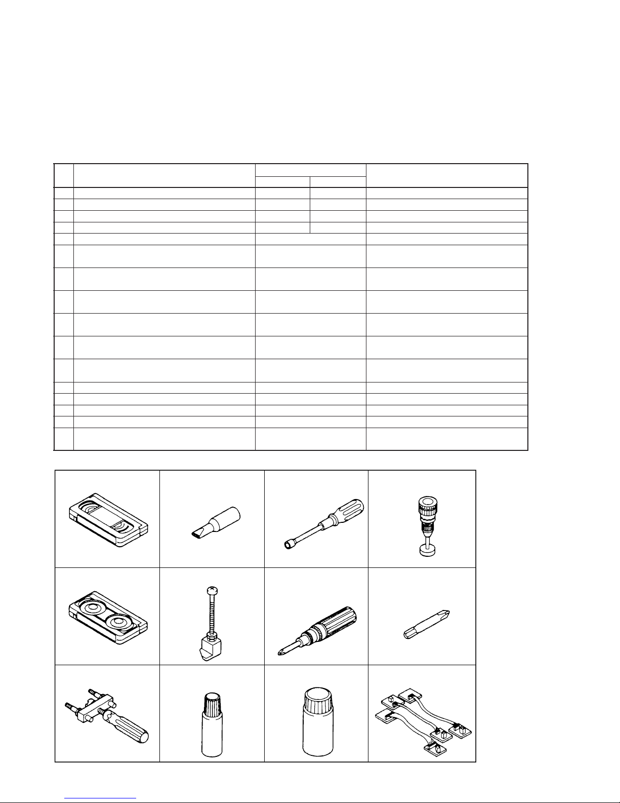
1-2. SERVICE TOOLS
1-2-1. SERVICE TOOLS
NOTES ON ALIGNMENT TAPES
Select a PAL or NTSC alignment tape from the list below, according to the transmission system of the VCR you are
repairing.
PAL: For models with 625 scanning lines and a field frequency of 50Hz
NTSC: For models with 525 scanning lines and a field frequency of 60Hz
VHJ-0005, VHJ-0006, VHJ-0007
VHJ-0003
VHJ-0102
VHJ-0048
VHJ-0014
VHJ-0100, VHJ-0101
VHJ-0045
VHJ-0016
VHJ-0099
No. 1, 2, 3, 4
No. 5
No. 6 No. 7
No. 8
No. 9
No. 10 No. 11
No. 12
No. 13
No. 14, 15 No. 16
VHJ-0106
VHJ-0041
VHJ-0004
Fig.1-2-1
No. Tool
Tool No.
Remarks
NTSC PAL
1 Alignment tape VHJ-0005 VHJ-0008 SP colour bar 1kHz (normal)
2 Alignment tape VHJ-0006 VHJ-0009 SP monoscope 7kHz (normal)
3 Alignment tape VHJ-0007 –––––––– EP monoscope
4 Alignment tape –––––––– VHJ-0052 LP monoscope
5 Eccentric screw driver VHJ-0003 Used to adjust the tape path
6 Nut box VHJ-0048
Used to adjust the height of the
lever load assembly
7 Torque dial gauge VHJ-0004
Used to measure reel winding
torque
8 Cassette torque meter VHJ-0016
Used to measure back tension
torque
9 Load lever assembly height adjustment tool VHJ-0102
Used to adjust the height of the
load lever assembly
10 Torque gauge screwdriver VHJ-0014
Used to adjust the tightening torque
of screws
11 3 mm dia. bit for torque screwdriver VHJ-0045
Used to replace the bit of the torque
gauge screwdriver
12 Video head removing tool VHJ-0041 Used to remove the upper cylinder
13 Oil VHJ-0099
14 Grease VHJ-0100
15 Grease VHJ-0101
16 Relay cables VHJ-0106
Relay cables of mechanism and
CP-1 PWB assembly
5-3
1-2-2. Using the Relay Cable (VHJ-0106)
The mechanism can be repaired without using the relay
cable (VHJ-0106). As shown in Fig. 1-3-1, the relay cable
(VHJ-0106) is a tool used for relay between the CP-1 PWB
assembly and mechanism unit.
When connecting it, take note of the pin number of the
connector.
NOTE 1: Do not place the mechanism upright as shown
in Fig. 1-3-1 when inserting/ejecting the cassette.
NOTE 2: For NTSC models, be sure to connect the VM-1
PWB assembly and CP-1 PWB assembly.
Mechanism unit
CP-1 PWB assembly
VM-1 (VP-1) PWB
assembly
Relay cable:
VHJ-0106
Fig. 1-2-2
Fig. 2-1-1
2. AN OVERVIEW OF THE MECHANISM
2-1. NAMES OF THE MAIN PARTS
2-1-1. CASSETTE MECHANISM ASSEMBLY
Under frame
Stand L
Release lever
Lid opener spring
Pinion gear
Lock gear
Gear holder
Drive gear
Tray lock
spring
Door opener
lever
5-4
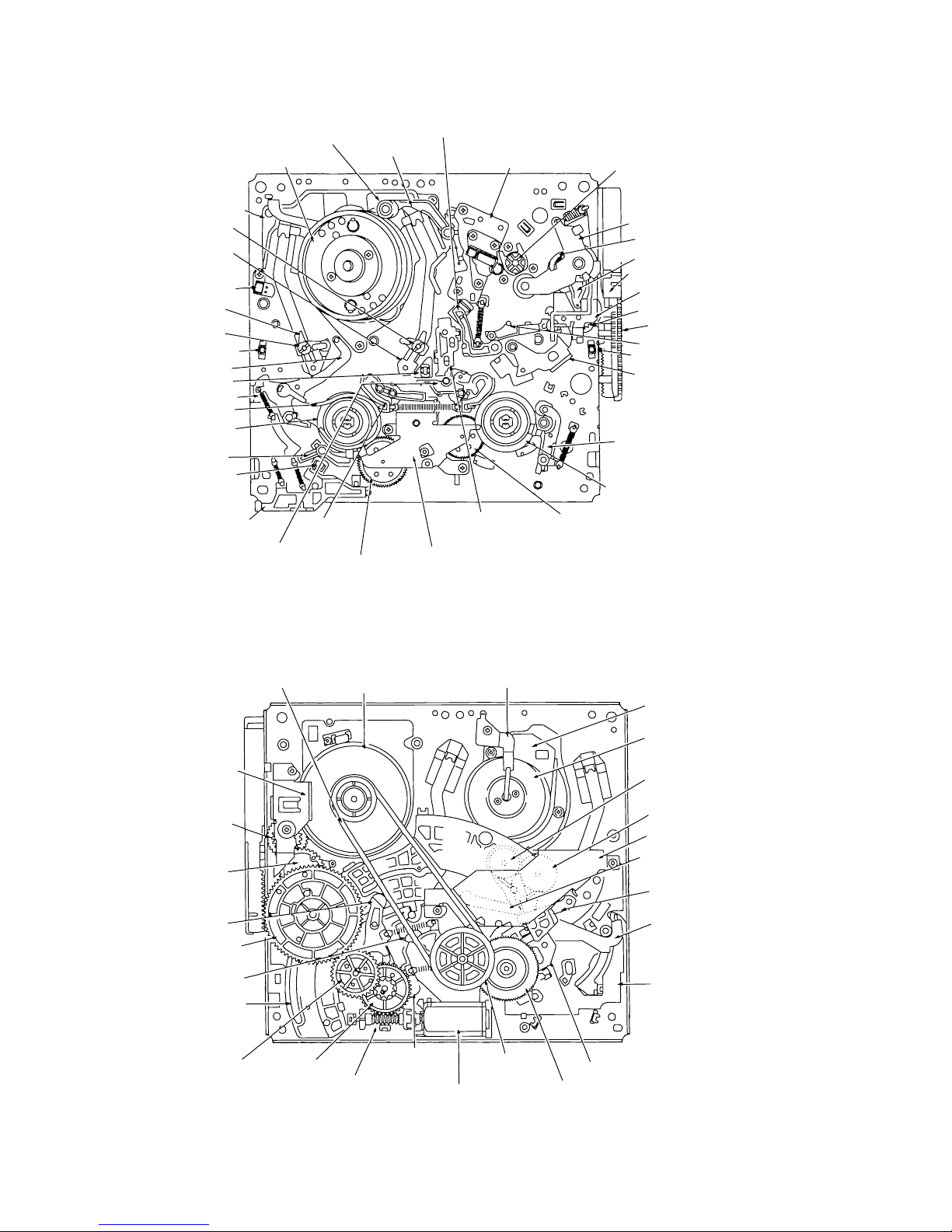
2-1-2. T OPVIEW
2-1-3. UNDERSIDE
Capstan motor
Pinch roller lever assembly
Pinch lift cam
Pinch lift mounting
Front rack gear
Opener mounting
Pinch cam gear
Start rack gear
Load lever assembly
Tape top sensor
L guide act lever assembly
T soft brake assembly
Take-up reel assembly
T reel gear
Cylinder (Drum)
Cleaner lever
Cleaner roller assembly
Capstan brake assembly
Audio R/P head assembly
(ACE head)
T brake act slide
Clutch mounting assembly
S reel gear
S brake
assembly
T brake assembly
EP sw lever
EP switch
S soft lever
Supply reel assembly
Band brake assembly
BT spring
Tape sensor LED
BT lever assembly
Tape end sensor
Guide roller assembly
S incline mounting assembly
Full erase head
T incline mounting assembly
Guide roller assembly
Cylinder mounting
Fig. 2-1-2
Fig. 2-1-3
Stator
Rotor
T load gear
S load gear
Crescent mounting
T load lever assembly
S load lever assembly
BT spring lever assembly
MC-1 PWB assembly
Reel belt
Capstan motor
Loading motor assembly
Reel pulley
Friction gear assembly
S brake act slide
Wheel gear 2 Wheel gear 1
Worm gear assembly
Cylinder earth
assembly
Brake act lever
assembly
Harness mounting
Pinch cam gear
Mode switch (S8001)
Brake control lever
Main cam
Clutch change lever
Crescent slide
5-5
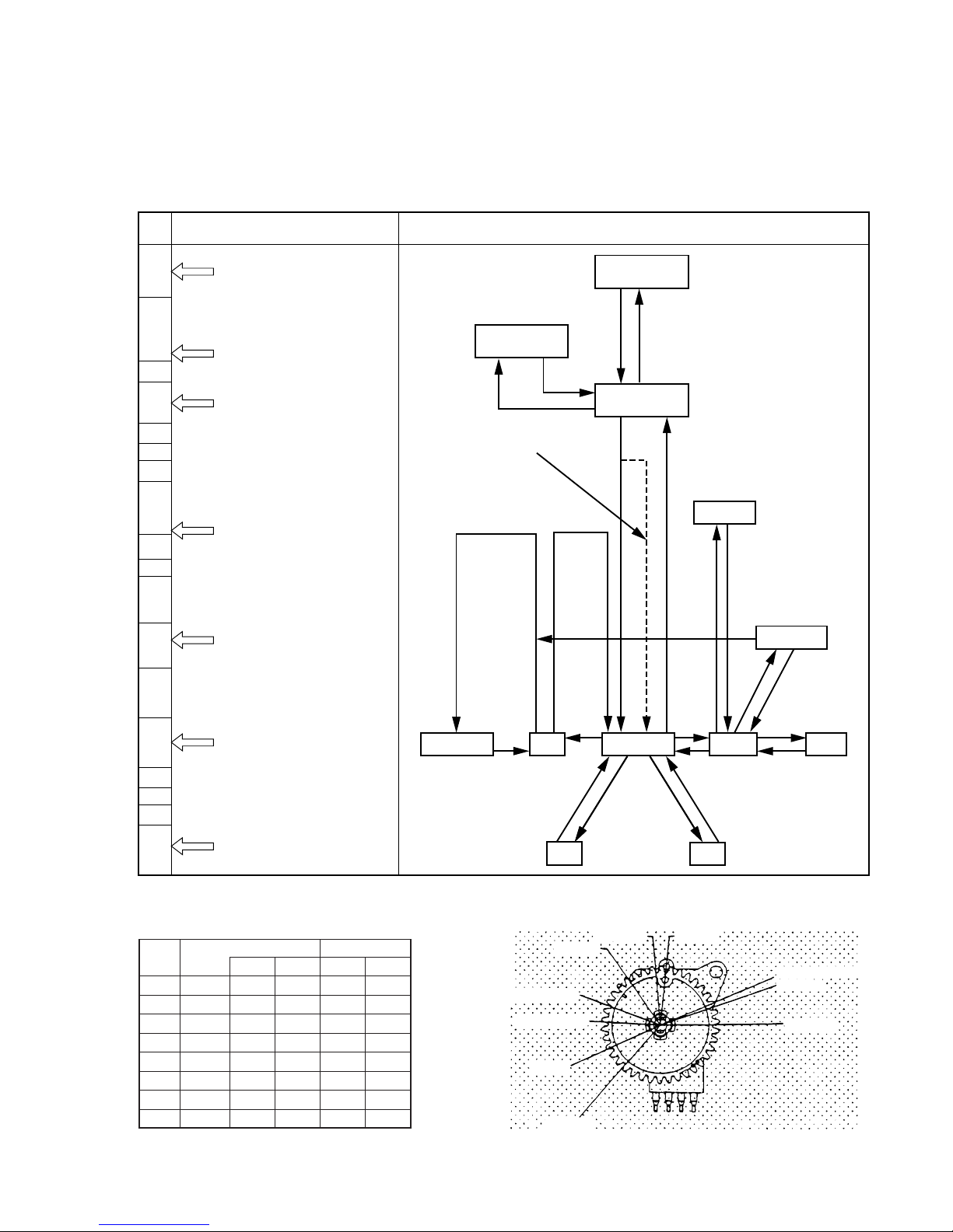
2-2. AN OVERVIEW OF THE MECHANISM MODES
2-2-1 . MECHANISM MODE SWITCHING TABLE
NOTE: The letters and figures enclosed in circles in the mechanism mode column are the codes on the crescent slide.
FF/REW EJECT
CASSETTE IN
IN REW
INITIAL
REVIEW
IDLER
STILL/SLOW
PLAY/STOP
BRAKE
Fig. 2-2-1
6
2
0
7
0
1
0
1
0
2
0
3
0
5
0
4
0
6
EJECT E
Distinguished by whether the
EP switch is ON or OFF.
Horizontal shift section.
Vertical shift section.
IN REW R
INITIAL 7
Cleaner roller assembly: ON
S/T mounting incline assembly
pressure begins.
S/T mounting incline assembly
pressure ends.
REVIEW 1
IDLER pos. 2
(Pinch roller OFF)
STILL/SLOW 3
PLAY/STOP 5
BRAKE pos. 4
FF/REW 6
CASSETTE OUT
(EJECT)
IN REW
(SHORT REW)
INITIAL
(POWER OFF)
The principal mode-switching states of the mechanism
Mechanism mode
HEX
DATA
When loading is carried out starting at
the CASSETTE IN position
REVIEW
STILL/SLOW
REC PAUSE REC STOP P LAY CUE
REW
FF
APPEARANCE OF MODE SWITCH AND
RELATIONSHIP BETWEEN MODE POSITIONS
MODE SWITCH OUTPUT TABLE
HEX SW DATA SW DATA 2
DATA 1 X Y Z
0 5.0V H H H 5V
1 5.0V H H L 0V
2 2.5V H L H 5V
3 2.5V H L L 0V
4 3.4V L H H 5V
5 3.4V L H L 0V
6 2.0V L L H 5V
7 2.0V L L L 0V
5-6
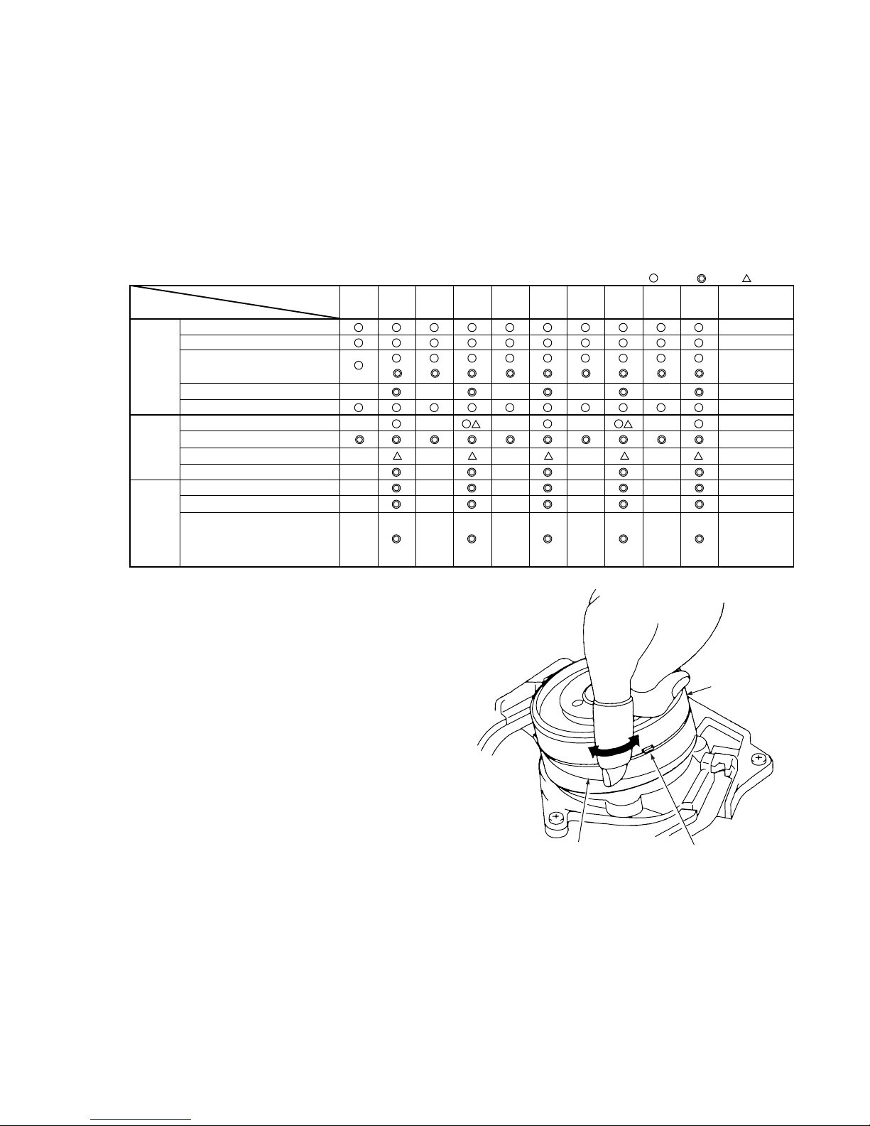
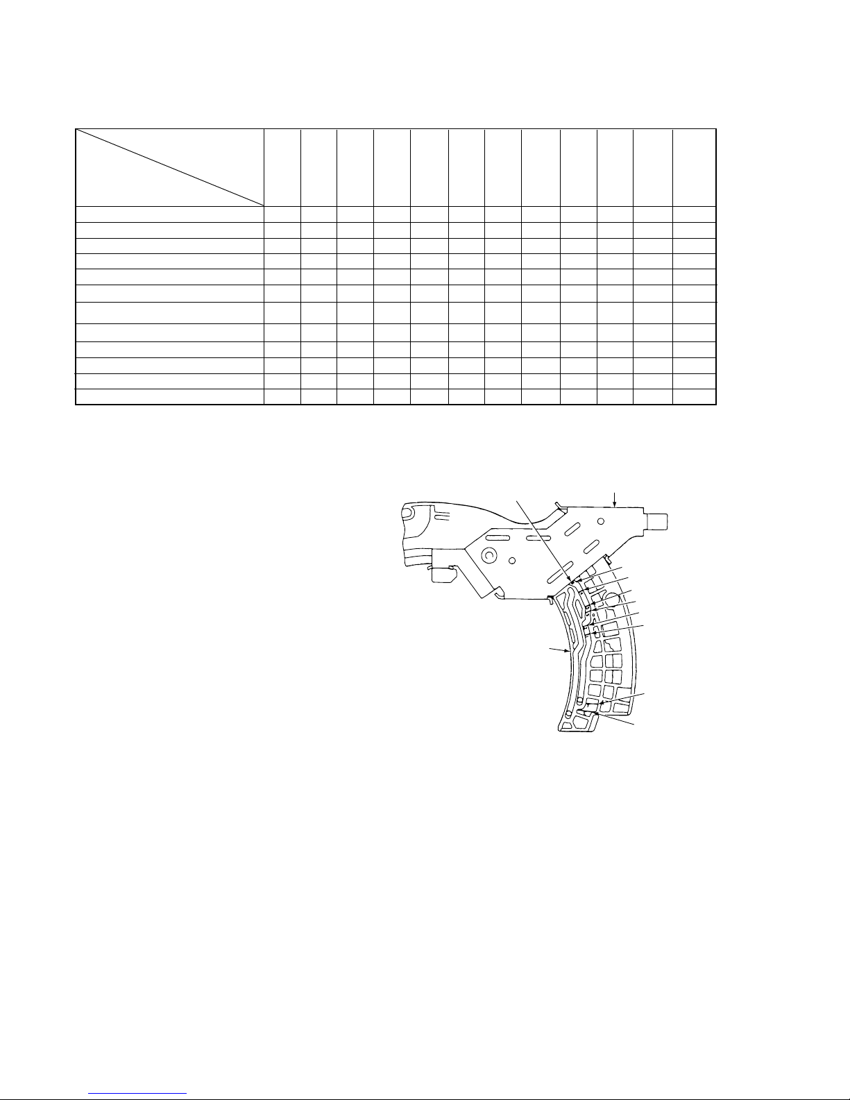
2-2-2. MOVEMENT CHECK LIST FOR THE MAIN PARTS OF THE MECHANISM
2-2-3. HOW TO CHECK THE MECHANISM MODE
POSITION
You can tell which mode the mechanism is currently in by
looking at the codes and marking-lines on the crescent
slide on the underside of the mechanism chassis. The
edge of the crescent mounting is used as the reference
line, as shown in Fig.2-2-2, and the marking-lines and
symbols indicating the mechanism modes are displayed
on the crescent slide, which slides against the edge of the
crescent mounting. The mechanism mode is read off from
the marking-line on the slide crescent which is aligned
with the reference-line on the crescent mounting.
Example: In Fig.2-2-2, marking-line 6 is aligned with the
reference-line on the crescent mounting , so the mechanism is seen to be in FF/REW mode.
2-2-4. SELF-DIAGNOSIS DISPLAY
Some models are equipped with the SELF-DIAGNOSIS
DISPLAYS function.
Use it as a means of finding out the symptoms and cause
of the error before performing repairs.
For details, refer to the separate service manual for the
respective models.
6: FF/REW
4: BRAKE
5: PLAY/STOP
3: STILL/SLOW
2: IDLER
1: REVIEW
7: INITIAL
(POWER OFF)
E: EJECT
Crescent slide
Crescent mounting
The edge of the
crescent mounting
is the reference-line
Fig. 2-2-2
(S): Strength (W): Weakness
T brake assembly OFF OFF ON ON ON OFF OFF OFF OFF ON
ON/OFF
S brake assembly OFF OFF OFF OFF OFF OFF OFF OFF OFF ON
ON/OFF
T soft brake assembly OFF OFF OFF ON ON ON ON OFF OFF OFF OFF
S soft lever ON ON ON ON ON OFF OFF OFF OFF OFF OFF
BT lever assembly OFF OFF OFF OFF OFF ON ON ON ON ON ON
BT spring OFF OFF OFF OFF OFF
ON(W) ON(W) ON(S) ON(S) ON(S) ON(W)
Pinch roller lever assembly UP UP UP
UP/ DOWN/
ON OFF ON ON OFF OFF
DOWN UP
Clutch mounting assembly PLAY PLAY PLAY PLAY PLAY PLAY PLAY PLAY PLAY PLAY FF
Load lever assembly UNLO UNLO UNLO LO LO LO LO LO L LO LO
Capstan brake assembly OFF OFF OFF OFF OFF OFF OFF ON OFF OFF OFF
S and T incline mounting assembly LO UNLO
Cleaner roller assembly OFF OFF OFF (ON) (ON) OFF OFF OFF OFF OFF OFF
Principal parts
Mechanism mode
EJECT
IN REW
INITIAL
(POWER OFF)
(LOADING)
(UNLOADING)
REV
IDLER
STILL/SLOW
PLAY/STOP
BRAKE
FF/REW
 Loading...