

Sony SLV-GA35, SLV-GA36, SLV-GA45, SLV-GA55, SLV-GA59 Service Manual
...
SLV-GA35/GA36/GA45
/
GA55/GA59
/
SERVICE MANUAL
Photo: SLV-GA59
• Refer to the SERVICE MANUAL of VHS MECHANICAL
ADJUSTMENTS VI for MECHANICAL ADJUSTMENTS.
(9-921-647-11)
GA65/GF85
/
GF86/SA34
RMT-V286/V286A/V286B/V286C
African Model
SLV-GA59
E Model
SLV-GA35MK2/GA45AV/GA55MK2
Middle East Model
SLV-GA45AV/GA55MK2/GA65MK2
Philippine Model
SLV-GA35MK2/GA55MK2/GF85MK2
Taiwan Model
SLV-GA36/GA45AV/GF86/SA34
Thailand Model
SLV-GA45AV/GF85MK2
S MECHANISM
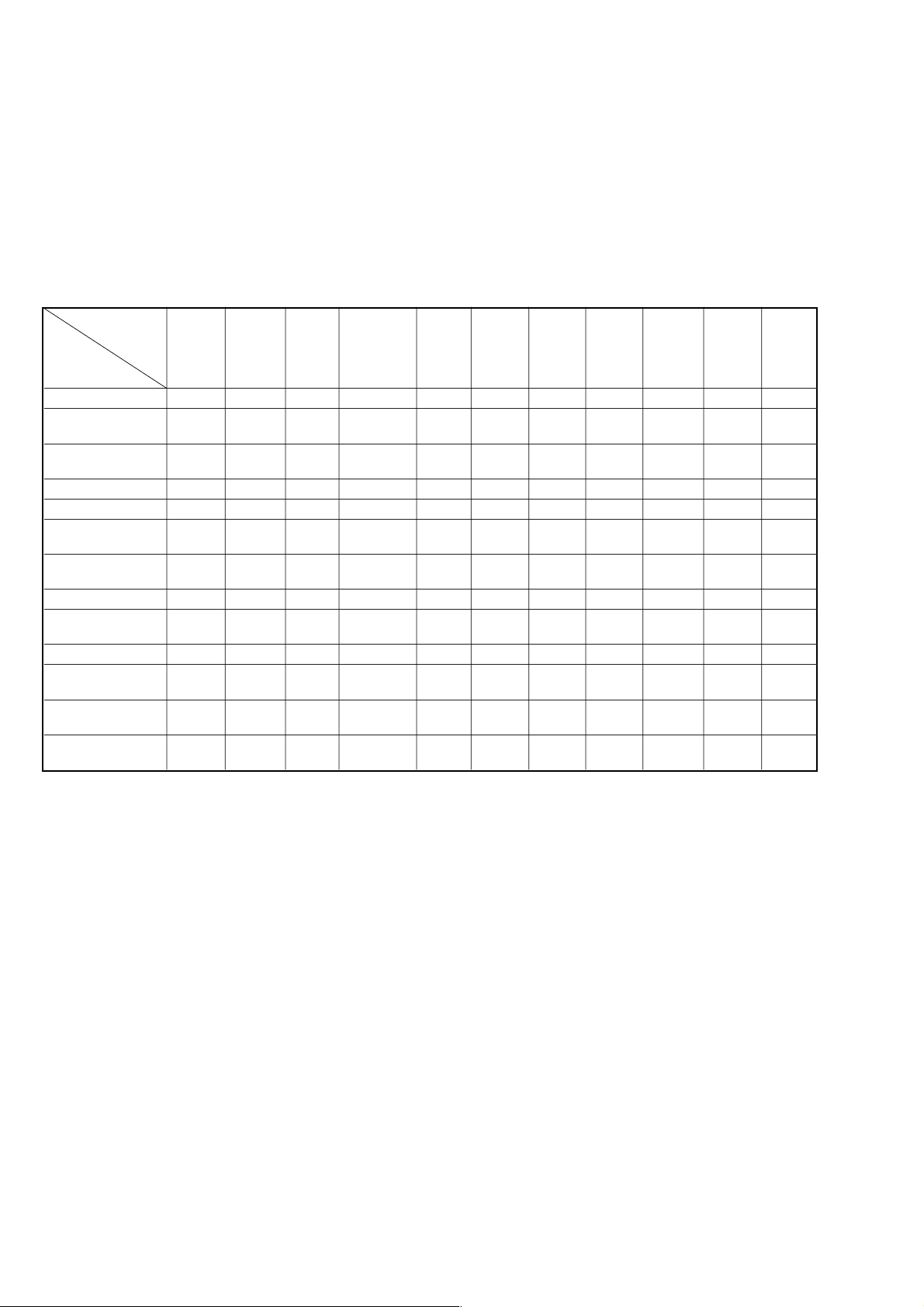
* The abbreviations of GA35, GA45, GA55, GA65 and GF85 contained in this service manual are indicated
when these models are common to all their corresponding models as given below.
Abbreviated
model name
All model
names
SLV-
SLV-GA35: E/GA45: E, ME, TH/
GA55: E, ME/GA59/GA65/GF85: TH
System
Colour
system
PAL, MESECAM, NTSC 3.58, NTSC 4.43
SECAM (GA59)
RF output signal
UHF channels 30 to 39
(B/G, D/K)
Aerial out
75-ohm asymmetrical aerial socket
SLV-GA35: PL/GA55: PL/GF85: PL/
GA36/GA45: TW/SA34/GF86
System
Colour system
PAL, MESECAM, NTSC 3.58 (GA35: PL/GA55: PL)
Format
VHS NTSC standar
Video recording system
Rotary head helical scanning FM system
Video heads
Double azimuth two heads
Video signal
NTSC color, EIA standards
GA35
GA35MK2
d
GA45
GA45AV
GA55 GA65 GF85
GA55MK2 GA65MK2
SPECIFICATIONS
Tape speed
SP: 33.35 mm/s
EP: 11.1
1 mm/s
LP: 16.67 mm/s (GA35: PL/GA55: PL)
Maximum recording/playback time
9 hrs. in EP mode (with T-180 tape)
Fast-forward and rewind time
Approx. 4 min. 30 sec. (with T-120 tape)
Tuner section
RF output channel
VHF channel 3 or 4
Antenna
75-ohm antenna terminal for VHF/UHF
Inputs and outputs
LINE 1 IN
VIDEO IN, phono jack (1)
Input signal: 1 Vp-p, 75 ohms,
unbalanced, sync negative
AUDIO IN, phono jack (2)
Input level: 327 mVrms
Input impedance: more than 47 kilohms
GF85MK2
LINE 1 OUT
VIDEO OUT, phono jack (1)
Output signal: 1 Vp-p, 75 ohms,
unbalanced, sync negative
AUDIO OUT, phono jack (2)
Standard output: 327 mVrms
Load impedance: 47 kilohms
Output impedance: less than 10 kilohms
General
Power requirements
110 – 240 V AC, 50/60 Hz
Power consumption
10 W (GA35: PL, E/GA36: TW/SA34)
12 W (GA45: E, ME, TH/GA55: PL, E,
ME/GA59/GA65/GF85: PL, TH/
GA45AV/GF86)
Operating temperature
5°C to 40°C
Storage temperature
–20°C to 60°C
– Continued on next page –
VIDEO CASSETTE RECORDER
Dimensions
Approx. 355 × 96 × 293 mm (w/h/d)
including projecting parts and controls
Mass
Approx. 3.8 kg
Supplied accessories
Remote commander (1)
R6 (Size AA) batteries (2)
75-ohm coaxial cable with F-type connectors (1)
(GA35: PL/GA55: PL/GF85: PL)
Aerial cable (1)
Audio/video cable (3-phono to 3-phono) (1) (GF85: PL, TH)
Audio/video cable (2-phono to 2-phono) (1) (GA45: E, ME)
Design and specifications are subject to change
without notice.
• Feature Difference
SLV-
GA35MK2: GA35MK2: GA36 GA45AV: E GA45AV: GA55MK2: GA59 GA65MK2 GF85MK2: GF85MK2: GF86
PL E SA34 GA45AV: ME TW PL PL TH
FEATURE
HEAD/CH 2/2 2/2 2/2 2/2 2/2 2/2 2/2 2/2 2/4 2/4 2/4
NTSC (3.58)
NTSC (4.43)
PAL (REC/PB) ×/a ×/a ×/× a/a ×/× a/aa/aa/a ×/× a/a ×/×
SECAM (REC/PB) ×/××/××/××/××/××/××/a ×/××/××/××/×
ME-SECAM
REC (NTSC)
REC (PAL) (SP/LP) ××× a × aaa × a/××
PLAY (NTSC)
PLAY (PAL) (SP/LP) aa× a × aaa × a/××
RCA REAR LINE
IN/OUT
MODULATOR
SYSTEM
REMOTE
COMMANDER
(REC/PB)
(REC/PB)
(REC/PB)
(SP/EP)
(SP/LP/EP)
RMT-
×/a ×/××/aa/aa/aa/aa/aa/aa/aa/aa/a
×/××/a ×/× a/a ×/××/× a/aa/a ×/× a/a ×/×
×/a ×/a ×/× a/a ×/× a/aa/aa/a ×/× a/a ×/×
××× aaaaaaa/× a
aaa/×/aaa/×/aa a aa/×/aa/×/× a/×/a
×/a (2P) ×/a (2P) ×/a (2P) a (2P) a (2P) a (2P) a (2P) a (2P) a (3P) a (3P) a (3P)
3/4 ch G/K 13 ch G/K 13 ch 3/4 ch G/K G/K 3/4 ch G/K 13 ch
V286A V286A V286C V286 V286B V286 V286 V286 V286 V286 V286B
GA45A V: TH
GA55MK2: E
GA55MK2: ME
• Abbreviation
ME : Middle East model
PL : Philippine model
TH : Thailand model
TW : Taiwan model
SAFETY CHECK-OUT
After correcting the original service problem, perform the following
safety checks before releasing the set to the customer:
1. Check the area of your repair for unsoldered or poorly-sol-
dered connections. Check the entire board surface for solder
splashes and bridges.
2. Check the interboard wiring to ensure that no wires are
“pinched” or contact high-wattage resistors.
3. Look for unauthorized replacement parts, particularly transis-
tors, that were installed during a previous repair. Point them
out to the customer and recommend their replacement.
SAFETY-RELATED COMPONENT WARNING!!
COMPONENTS IDENTIFIED BY MARK 0 OR DOTTED
LINE WITH MARK 0 ON THE SCHEMATIC DIAGRAMS
AND IN THE PARTS LIST ARE CRITICAL TO SAFE
OPERATION. REPLACE THESE COMPONENTS WITH
SONY PARTS WHOSE PART NUMBERS APPEAR AS
SHOWN IN THIS MANUAL OR IN SUPPLEMENTS PUBLISHED BY SONY.
4. Look for parts which, though functioning, show obvious signs
of deterioration. Point them out to the customer and recommend their replacement.
5. Check the B+ voltage to see it is at the values specified.
– 2 –

TABLE OF CONTENTS
Section Title Page Section Title Page
Feature Difference................................................................... 2
SERVICE NOTE ...................................................................... 4
1. GENERAL
Getting Started .............................................................. 1-1
Basic Operations ........................................................... 1-2
Additional Operations.................................................... 1-3
Additional Information ................................................... 1-5
2. DISASSEMBLY
2-1. Upper Case Removal .................................................... 2-1
2-2. Front Panel Section Removal ........................................ 2-1
2-3. Rear Panel Removal ..................................................... 2-1
2-4. Mechanism Deck Removal............................................ 2-1
2-5. MA-366 Board Removal ................................................ 2-2
2-6. Internal Views ................................................................ 2-3
2-7. Circuit Boards Location ................................................. 2-4
6. ADJUSTMENTS
6-1. Mechanical Adjustments ............................................... 6-1
6-2. Electrical Adjustments ................................................... 6-1
2-1. Pre-Adjustment Preparations ........................................ 6-1
2-1-1. Instruments to be Used............................................ 6-1
2-1-2. Connection ............................................................... 6-1
2-1-3. Set-up of Adjustment ............................................... 6-1
2-1-4. Alignment Tapes....................................................... 6-1
2-1-5. Specified I/O Level and Impedance......................... 6-1
2-1-6. Adjusting Sequence ................................................. 6-2
2-2. Power Supply Adjustment ............................................. 6-2
2-2-1. Power Supply Check ................................................ 6-2
2-3. Ser vo System Adjustment ............................................. 6-2
2-3-1. RF Switching Position Adjustment........................... 6-2
2-4. Audio System Adjustments ........................................... 6-3
2-4-1. Hi-Fi Audio System Adjustment ............................... 6-3
1. AF Switching Position Adjustment........................... 6-3
2-4-2. Normal Audio System Adjustment........................... 6-3
1. ACE Head Adjustment ............................................. 6-3
2. E-E Output Level Check........................................... 6-3
2-5. Parts Arrangement Diagram for Adjustments ............... 6-4
3. BLOCK DIAGRAMS
3-1. Overall Block Diagram................................................... 3-1
3-2. Video Block Diagram ..................................................... 3-3
3-3. Ser vo/System Control Block Diagram .......................... 3-5
3-4. Audio Block Diagram ..................................................... 3-7
3-5. Mode Control Block Diagram ........................................ 3-9
3-6. Power Block Diagram .................................................... 3-11
4. PRINTED WIRING BOARDS AND
SCHEMATIC DIAGRAMS
4-1. Frame Schematic Diagram............................................ 4-3
4-2. Printed Wiring Boards and Schematic Diagrams ......... 4-5
MA-366 Printed Wiring Board ....................................... 4-5
MA-366 (Video, Audio) Schematic Diagram................. 4-9
MA-366 (OSD, Servo/System/Mode Control)
Schematic Diagram ....................................................... 4-13
MA-366 (HiFi Audio, I/O, Tuner)
Schematic Diagram ....................................................... 4-15
MA-366 (Power Supply) Schematic Diagram ............... 4-17
SE-119 Printed Wiring Board........................................ 4-20
SE-119 Schematic Diagram.......................................... 4-21
FR-167 Printed Wiring Board and
Schematic Diagram ....................................................... 4-23
5. INTERFACE, IC PIN FUNCTION DESCRIPTION
7. REPAIR PARTS LIST
7-1. Exploded Views ............................................................. 7-1
7-1-1. Front Panel and Cabinet Assemblies....................... 7-1
7-1-2. Chassis Assembly.................................................... 7-3
7-1-3. Mechanism Chassis Assembly (1) ........................... 7-4
7-1-4. Mechanism Chassis Assembly (2) ........................... 7-5
7-1-5. Mechanism Chassis Assembly (3) ........................... 7-6
7-2. Electrical Parts List ....................................................... 7-7
5-1. System Control-Video Block Interface
(MA-366 BOARD IC101)............................................... 5-1
5-2. System Control-Servo Peripheral Circuit Interface
(MA-366 BOARD IC101)............................................... 5-1
5-3. System Control-Mechanism Block Interface
(MA-366 BOARD IC101)............................................... 5-2
5-4. System Control-Audio Block Interface
(MA-366 BOARD IC101)............................................... 5-3
5-5. Servo/System Control Microprocessor
Pin Function (MA-366 BOARD IC101) ......................... 5-4
– 3 –
SERVICE NOTE
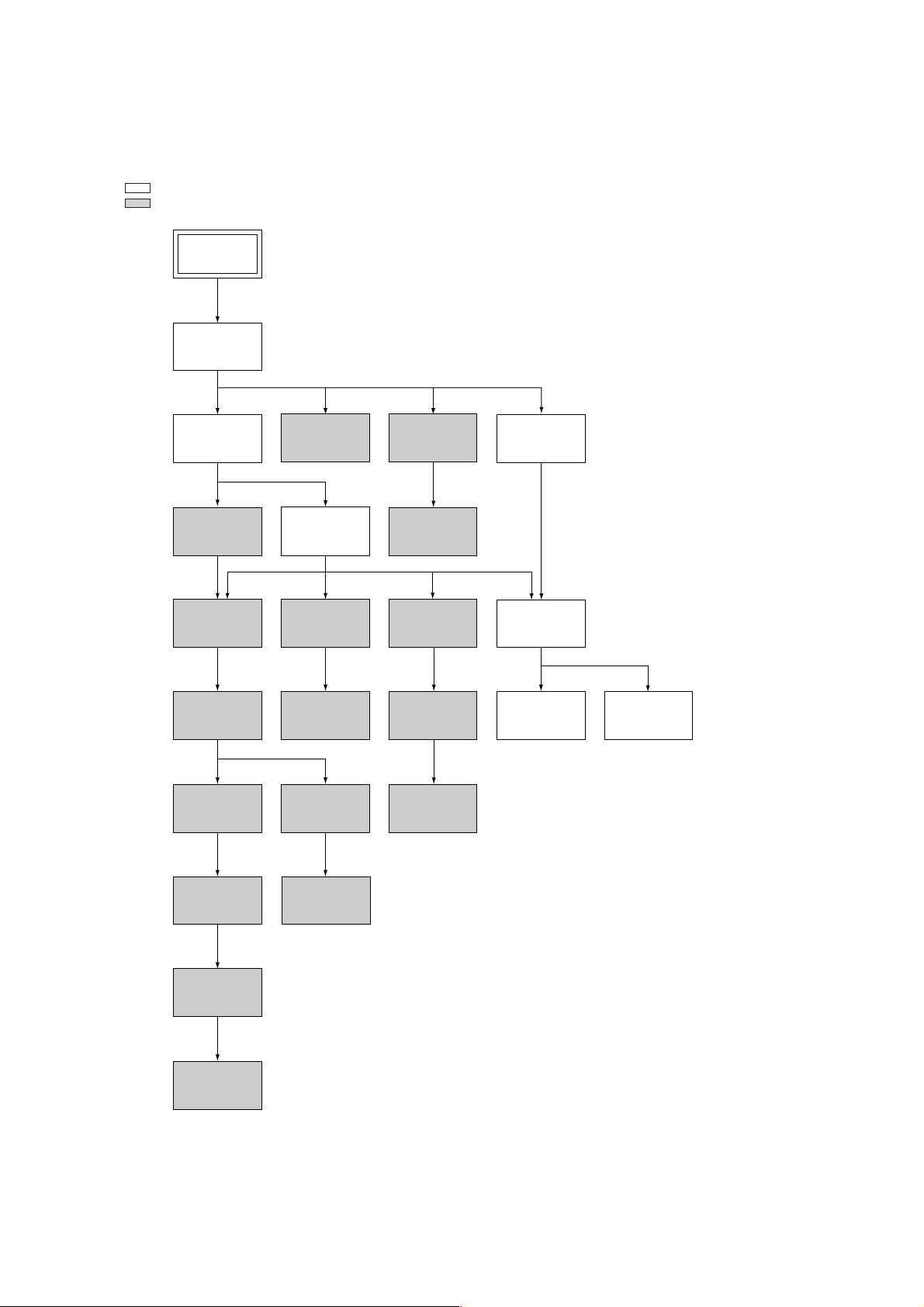
1. DISASSEMBLY
• This set can be disassembled in the order shown below.
Note: Pages in indicated pages in the SERVICE MANUAL.
Pages in indicated pages in the VHS MECHANICAL ADJUSTMENT MANUAL VI.
Set
Upper case
(Page 2-1)
Front Panel
Section
(Page 2-1)
FL Complete
Ass’y
(Page 13)
Retainer
Plate
(Page 22)
FL Slider
Block Ass’y
(Page 22)
Cam Gear
(Page 23)
Pinch Press
Block Ass’y
(Page 14)
Mechanism
Deck
(Page 2-1)
Rubber
Belt
(Page 15)
Capstan
Motor
(Page 15)
Cam Motor
Retainer
(Page 31)
Ground Shaft
Ass’y
(Page 13)
Drum
Ass’y
(Page 13)
Rubber
Belt
(Page 15)
Pully Gear
Ass’y
(Page 29)
Reel Direct
Ass’y
(Page 30)
Rear
Panel
(Page 2-1)
MA-366
Board
(Page 2-2)
Rotary
Switch
(Page 2-2)
Tuner
Unit
Rubber
Belt
(Page 15)
Slider
(Page 26)
Loading
Gear (T, S)
(Page 28)
Cam Motor
(Page 31)
– 4 –
SLV-GA35/GA36/GA45/GA55/GA59/GA65/GF85/GF86/SA34
Getting Started
7
Getting Started
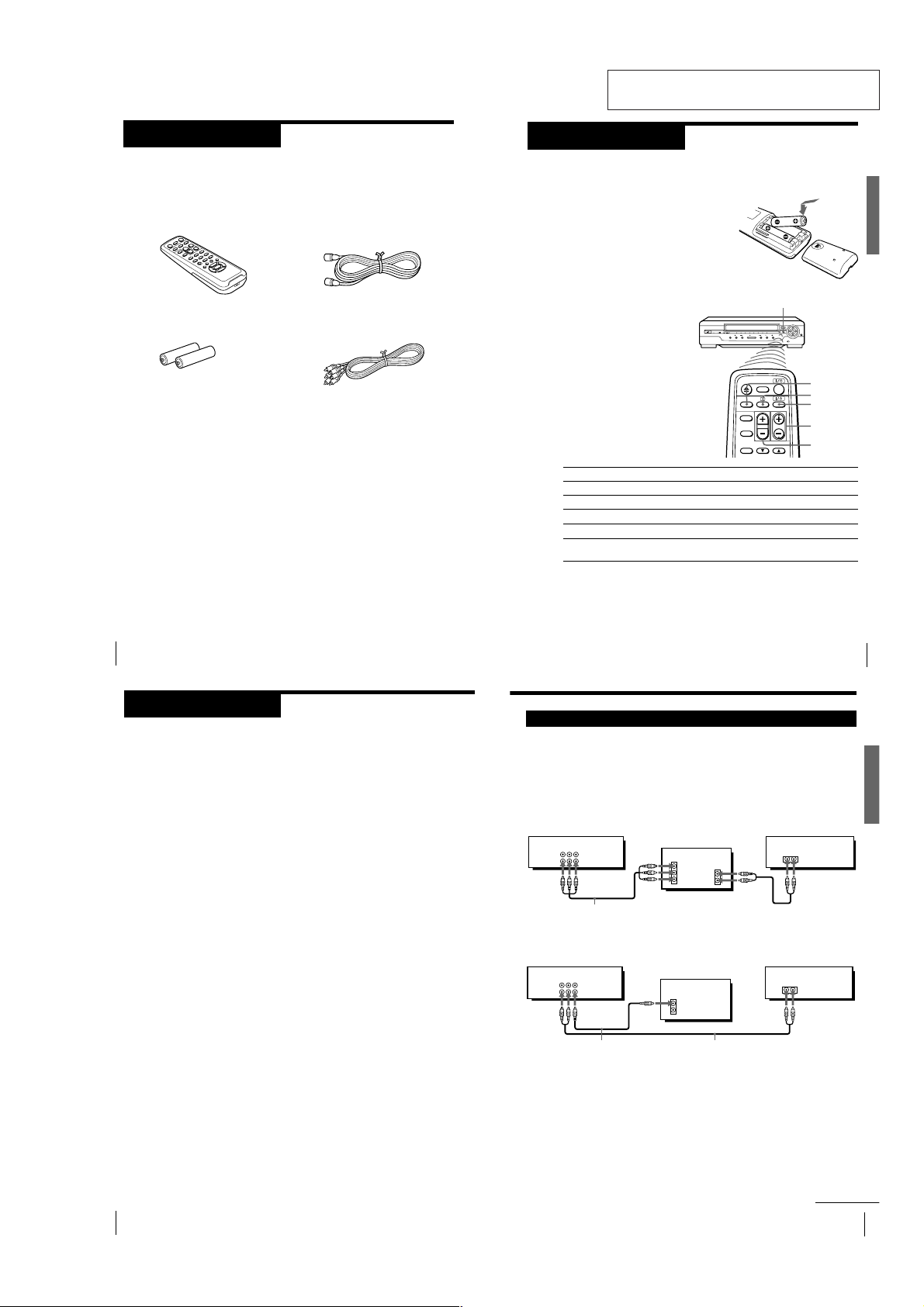
Audio/video (A/V) hookup
If your TV has audio/video (A/V) input jacks, you will get a better picture
and sound if you hook up your unit using these connections.
You should also connect the audio outputs of your unit or TV to your stereo
system for a true “home theater” experience.
If your TV does not have A/V inputs, see page 8 for antenna hookup.
A Use this hookup if your TV has stereo jacks
B Use this hookup if your TV does not have stereo jacks
This unit
Stereo receiver
TV
TV
This unit
Stereo receiver
Video cable (not supplied) Audio cable (not supplied)
Audio/video cable (supplied)
continued
IN
VIDEO
AUDIO
AUDIO OUT
AUX IN
AUDIO VIDEO
LINE 1 IN
LINE 1 OUT
AUDIO VIDEO
LINE 1 IN
LINE 1 OUT
VIDEO
AUDIO
IN
AUX IN
Getting Started
Step 1
Unpacking
Check that you have received the following items with the unit:
• Remote commander
• R6 (Size AA) batteries
Getting Started
4
• 75-ohm coaxial cable with F-type
connectors
• Audio/video cable (3-phono to 3phono)
SECTION 1
GENERAL
Setting up the remote commander
This section is extracted from SLV-GF86
instruction manual. (3-063-089-11)
Step 2
Inserting the batteries
Insert two R6 (size AA) batteries by
matching the + and – on the batteries to
the diagram inside the battery
compartment.
Insert the negative (–) end first, then push
in and down until the positive (+) end
clicks into position.
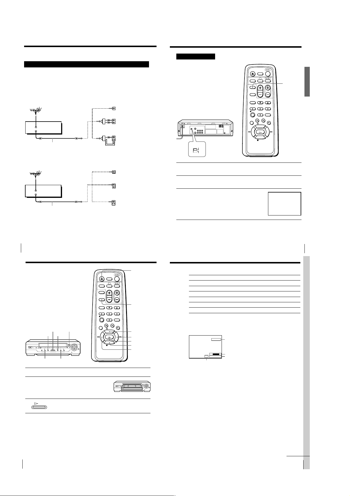
Using the remote commander
You can use this remote
commander to operate the unit
and a Sony TV. To operate this
unit, point at the remote sensor
on the unit. To operate the TV,
point at the remote sensor on
the TV. Buttons in the shaded
area of the remote commander
can be used to operate your
Sony TV. If the TV does not
have the g symbol near the
remote sensor, this remote
commander will not operate
the TV.
To
Turn the TV to standby or active mode
Turn on the TV power
Increase (+) or decrease (–) the TV volume
Change the TV program position
Select an input source of the TV either from antenna
in or from line in
Notes
• With normal use, the batteries should last about three to six months.
• If you do not use the remote commander for an extended period of time, remove
the batteries to avoid possible damage from battery leakage.
• Do not use a new battery with an old one.
• Do not use different types of batteries.
Remote sensor
Press
?/1 (power)
a (TV power)
VOL +/–
PROG (CH) +/–
TV/VIDEO
TV/VIDEO
a (TV power)
?/1
(on/standby)
PROG (CH) +/–
VOL +/–
Getting Started
Getting Started
5
Step 3
Hookups
Selecting the hookup
There are basically two ways to hook up this unit depending on whether
your TV has audio/video inputs or not.
If your TV has audio/video inputs
See “Audio/video (A/V) hookup” on page 7.
If your TV does not have audio/video inputs
See “Antenna hookup” on pages 8 and 9.
Before you get started
• Turn off the power to all equipment.
• Do not connect the AC power cords until all of the connections are
completed.
• Be sure you make connections firmly. Loose connections may cause
picture distortion.
• If your TV does not match any of the examples provided, see your nearest
Sony dealer or qualified technician.
Getting Started
6
1-1
Getting Started
9
Getting Started
TV/VIDEO
When connecting the unit to the TV
using only the antenna cable, you must
set the RF UNIT switch on the rear of the
unit so that the TV can receive the correct
signal from the unit.
1 Set the RF UNIT switch to CH 3 or CH 4, whichever channel is not
used in your area. If both are used, set the switch to either channel.
2 Press TV/VIDEO to turn on the VIDEO indicator in the display
window.
3 Turn on your TV and set it to the channel
you selected in step 1 (channel 3 or 4).
The video picture on the right will be
clearly displayed on the TV screen.
Whenever you use the unit, set the TV to
the channel selected in step 1.
Antenna hookup: Video cassette player setup
SONY
VIDEO CASSETTE PLAYER
RF UNIT
CH4
CH3
Basic Operations
11
Basic Operations
Additional tasks
To
Stop play
Pause play
Resume play after pause
Fast-forward the tape
Rewind the tape
Eject the tape
Press
x STOP
X PAUSE
X PAUSE or H PLAY
M FF (# M FF on the unit) during stop
m REW (m 3 REW on the unit) during stop
Z EJECT
continued
To view the tape status on the screen
Press DISPLAY.
The following information appears on the TV screen.
Audio monitor mode*
Remaining tape length
Time counter
Tape speed*
* Appears for a few seconds when the DISPLAY button is pressed and when the
mode is changed.
To turn the display off, press DISPLAY again.
Notes
• You can eject a tape even when the power is off. When you press Z EJECT, the unit
turns on automatically. After ejecting the tape, the unit turns off again.
• When the pause mode lasts for more than approximately five minutes, the unit will
automatically enter the playback mode.
• You can play back tapes recorded in the SP and EP mode.
• The counter resets to “0:00:00” whenever a tape is inserted.
• The counter stops counting when it comes to a portion with no recording.
SP
STEREO
::
22
SE
–
000
Step 3: Hookups (continued)
Antenna hookup
Make the following connections if your TV does not have A/V inputs.
A Use this hookup if you are using:
• VHF/UHF antenna (you get channels 2–13 and channels 14 and higher)
• UHF-only antenna (you get channels 14 and higher)
• Separate VHF and UHF antennas
Rear of TV
VHF/UHF
or
This unit
VHF/UHF
IN
OUT
Antenna cable (supplied)
B Use this hookup if you are using a VHF-only antenna (you get
channels 2–13 only)
This unit
VHF/UHF
IN
OUT
Antenna cable (supplied)
If you cannot connect your antenna cable to the unit directly
If your antenna cable is a flat cable (300-ohm twin lead cable), attach an external
antenna connector (not supplied) so you can connect the cable to the VHF/UHF IN
connector. If you have separate cables for VHF and UHF antennas, you should use a
U/V band mixer (not supplied). For details, see page 23.
VHF
UHF
or
VHF
UHF
Rear of TV
VHF/UHF Match the type of
or
VHF
UHF
or
VHF
UHF
A
Match the type of
connector on your
TV: A, B, or C.
B
C
connector on your
A
TV: A, B, or C.
B
For connector types
B and C, no UHF
connection is
required.
C
Getting Started
8
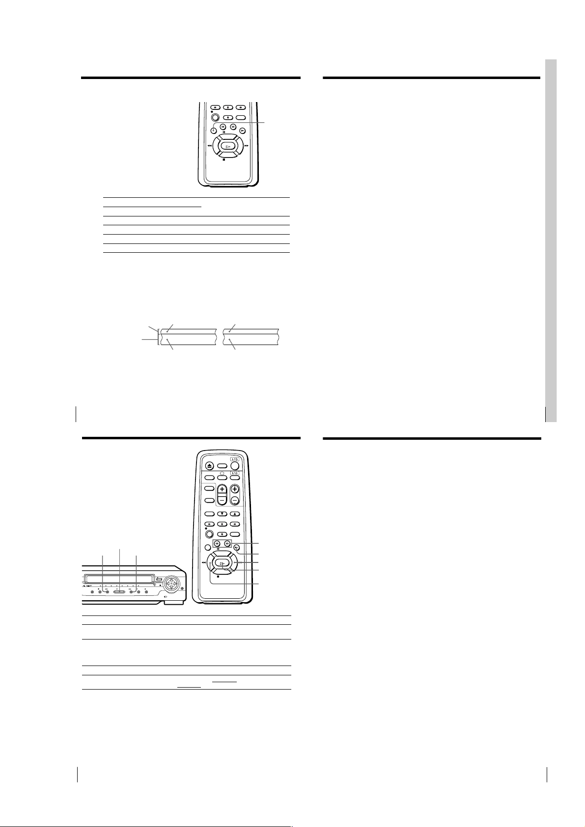
Basic Operations
Playing a tape
A EJECT
H PLAY
m 3 REW
# M FF
x STOP
X PAUSE
1 Turn on your TV and set it to the video channel.
2 Insert a tape.
3 Press H PLAY (if playback did not start in step 2).
Basic Operations
10
The unit turns on and starts playing
automatically if you insert a tape with
its safety tab removed.
PLAY
When the tape reaches the end, it will rewind automatically.
Z EJECT
DISPLAY
X PAUSE
M FF
H PLAY
x STOP
m REW
1-2
Playing a tape (continued)
Basic Operations
13
Basic Operations
Turning on the unit and TV, and starting playback
automatically (Trinitron TV Synchro Play)
You can only use this function if your TV is made by Sony (Trinitron TV).
Connections necessary to use this function
Connect the unit and TV with the audio/video cable (see “Audio/video
(A/V) hookup” on page 7.) Be sure to connect the audio/video cable to the
VIDEO IN 1 jacks on the TV if the TV has two or more inputs. The TV must
be placed where it will respond to the remote commander while you are
pointing it at the unit.
Operation
Make sure that the TV’s power is in standby mode.
Press TRINITRON TV SYNCHRO PLAY and hold the remote commander in
place for about two seconds.
The unit and TV turn on, and the TV is set to the video channel. If there is a
tape in the unit, playback starts automatically.
Notes
• If the Trinitron TV Synchro Play function does not work properly:
- Wait a few moments, and press the button again.
- Replace both of the batteries in the remote commander with new ones, and press
the button again.
Note that this function may not operate some Sony TVs because of the remote
commander’s signal limitations.
• Do not press TRINITRON TV SYNCHRO PLAY while playing back a video tape. If
you do so, the TV’s input source will momentarily switch to the TV’s tuner.
Additional Operations
15
To resume normal playback
Press H PLAY.
Tips
• You can adjust the tracking just by pressing V/v TRACKING NORMAL/SLOW/
STILL ADJUST while playing a tape.
• Adjust the picture using V/v TRACKING NORMAL/SLOW/STILL ADJUST if:
– streaks appear while playing in slow motion
– the picture shakes during pause
Notes
• Streaks or snow cannot be eliminated completely in the various playback
operations, especially in the slow motion mode.
• The sound is muted during these operations.
• On screen symbols may shake while playing or searching at various speeds.
Selecting the sound
during playback
Press AUDIO MONITOR to select
the sound you want. Each press
of the button changes the
indicator in the display window.
When you play a tape recorded in
stereo or with a bilingual sound
track, the Hi-Fi indicator in the
display window lights up.
AUDIO
MONITOR
To listen to a
Stereo tape’s
Stereo sound
Left channel
Right channel
Standard sound*
1
*
Usually the mixed sound of left and right channels (monaural)
2
*
Usually the main sound (monaural)
How sound is recorded on a video tape
The unit records sound onto two separate tracks. Hi-fi audio is recorded
onto the main track along with the picture. Monaural sound is recorded onto
the normal audio track along the edge of the tape.
Normal audio track
(monaural)
Hi-fi audio track
(main track)
Notes
• To listen to playback sounds in stereo, you must use the AUDIO OUT connections.
• When you play back a tape recorded in monaural, the sound is heard in monaural
regardless of the AUDIO MONITOR setting.
• You cannot select the sound to listen to while recording.
Basic Operations
12
Additional Operations
Playing/searching
at various speeds
Bilingual tape’s
Main and sub sounds
Main sound
Sub sound
1
Standard sound*
2
Stereo Bilingual
Usually mixed
left/right channels
Stereo sound
(left/right channels)
Press AUDIO MONITOR until the
display window indicator shows
L/R
L
R
No indication
Usually main
sound
Main (left channel)
Sub (right channel)
14
H PLAY
# M FFm 3 REW
Playback options
View the picture during fastforward or rewind
Play at high speed
Play in slow motion
Rewind and start play
Additional Operations
Operation
During fast-forward, hold M FF (# M FF on the unit) down.
During rewind, hold m REW (m 3 REW on the unit) down.
• During playback or pause, press # SEARCH or 3 SEARCH .
• During playback or pause, hold down M FF (# M FF on
the unit) or m REW (m 3 REW on the unit).
When you release the button, normal playback resumes.
During playback or pause, press y SLOW.
During stop, press · PLAY
m 3 REW
on the unit.
3/#
SEARCH
y SLOW
M FF
H PLAY
m REW
on the unit while holding down
1-3
Adjusting the
Additional Operations
17
Adjusting the tracking
Press V/v TRACKING NORMAL/SLOW/STILL ADJUST to obtain the best
possible picture. The distortion should disappear as you press one of the two
buttons. If you cannot get a clear picture with manual adjustment, press
TRACKING AUTO/MANU to return to automatic adjustment.
About Adaptive Picture Control (APC)
Adaptive Picture Control (APC) automatically improves recording and
playback quality by adjusting the unit to the condition of the video heads
and tape.
APC playback
The APC function automatically works on all types of tapes, including rental
tapes and tapes that were not recorded with APC.
APC recording
Whenever you insert a tape and start recording, the unit adjusts to the tape
using the APC function. This adjustment is retained until the tape is ejected.
Tip
• Adjust the picture using V/v TRACKING NORMAL/SLOW/STILL ADJUST if:
– streaks appear while playing in slow motion
– the picture shakes during pause.
Notes
• The auto tracking function works automatically when you play back a tape just
after inserting it.
• There is a delay of a few seconds before the unit actually starts recording while the
unit analyzes the tape. To avoid the delay, first set the unit to recording pause and
press z REC to have the unit analyze the tape. After ten seconds, press X PAUSE to
start recording immediately. If you press X PAUSE
before ten seconds, the APC
function is canceled.
• Sufficient picture quality may not be obtained when playing back tapes recorded on
another VCR or tapes in poor condition.
• When a tape recorded with the copyguard system is played back, intermittent
distortion may appear in the upper portion of the picture. However, this is not a
malfunction of the unit.
Additional Operations
19
Operation (when
recording on this unit)
You can make a copy of a tape using
this unit for recording or playback.
The unit cannot record TV
programs directly since it does not
have a TV tuner.
Before you start editing
• Turn on your TV and set it to the
video channel.
1
Set TAPE SPEED to select the tape speed, SP or EP. EP (Extended Play)
provides a recording time three times as long as SP (Standard Play).
However, SP produces better picture and sound quality.
2
Insert a source tape with its safety tab removed into the other
(playback) VCR. Search for the point to start playback and set it to
playback pause.
3
Insert a tape with its safety tab in place into this (recording) unit.
Search for the point to start recording and press X PAUSE.
4
Press z REC on this unit to set it to recording pause.
5
To start editing, press the X PAUSE buttons on both units at the same
time.
To stop editing
Press the x STOP buttons on both units.
To check the remaining tape length
Press DISPLAY.
The white bar indicates the approximate length of the tape recording.
Remaining tape length
Time counter
TAPE SPEED
To turn the display off, press DISPLAY again.
::
22
SSPE
–
000
X PAUSE
z REC
continued
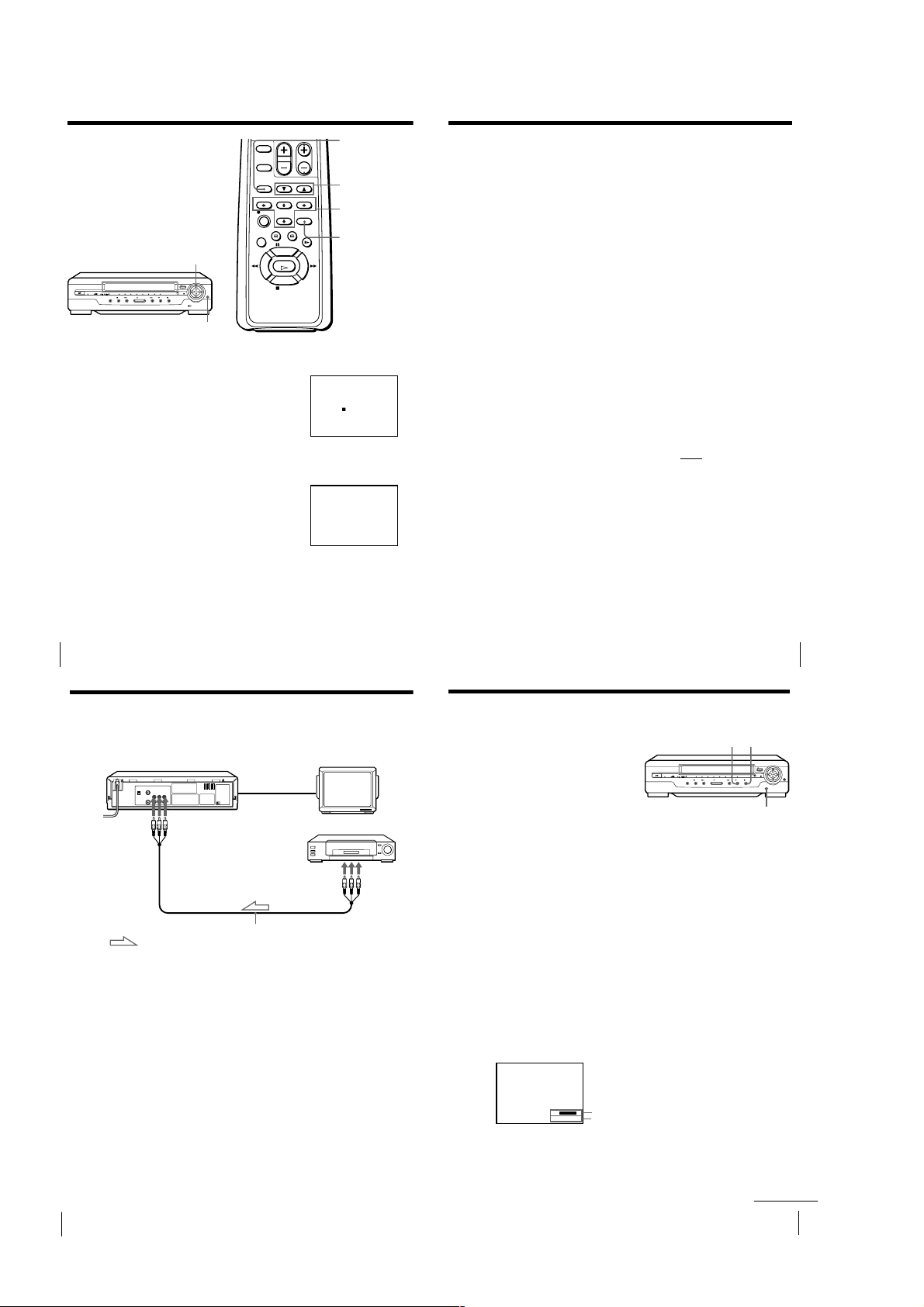
picture
AUTO/MANU
Although the unit automatically adjusts
the picture when playing a tape,
distortions or noise may occur if the tape
was recorded in poor condition. If so,
manually adjust the resolution, color and
tracking.
RESOLUTION CONTROL
buttons
STD PICT
Adjusting the resolution and color
1
While playing a tape, press M/m/</,
Resolution Control (v/V/b/B button on the
unit) so that the adjustment menu appears on
the TV screen.
2
Press </, Resolution Control (b/B button
on the unit) to get a clearer picture.
3
Press M/m Resolution Control (v/V button on the unit) to get the best
picture color.
Wait for several seconds until the adjustment menu disappears.
To resume the automatic adjustment
Press STANDARD PICTURE on the remote
commander (STD PICT on the unit). The
adjustment menu appears for a few seconds, then
disappears.
C
•••••
O
•••••
L
•••
O
+
••••••
•••••
R
RESOLUTION
C
•••••
O
•••••
•••
L
O
••••••
•••••
R
RESOLUTION
V/v TRACKING
NORMAL/SLOW/
STILL ADJUST
M/m/</,
Resolution
Control
STANDARD
PICTURE
+
Additional Operations
16
Editing with another VCR
How to connect to record on this unit
This unit (Recorder)
Tip
• If the other VCR is a monaural type and connected to the LINE 1 IN jacks on this
unit, the sound is recorded only on the channel whose jack is connected to the audio
plug. To record on both right and left channels, connect the audio plugs to AUDIO
R/L jacks using the VMC-910HG (3-phono to 2-phono) audio/video cable (not
supplied).
Notes
• Make sure you connect the plugs to jacks of the same colour.
• If you connect this unit to both the LINE IN and LINE OUT jacks of the other VCR,
select the input correctly to prevent a humming noise.
• Make sure you set the CONNECT LINE-1 switch to OTHERS.
LINE 1 IN
VMC-810HG audio/video cable (not supplied)
: Signal flow
Other VCR (Player)
LINE OUT
TV
Additional Operations
18
1-4
Editing with another VCR (continued)
To save a recording
To prevent accidental erasure, break off the safety
tab as illustrated. To record on a tape again, cover
the tab hole with adhesive tape.
Tips
• To edit more precisely, press the X PAUSE buttons
• To cut out unwanted scenes while editing, press X PAUSE on this unit when an
unwanted scene begins. When that scene ends, press X PAUSE again to resume
recording.
on the units to release pause.
Safety tab
Synchronized recording
The Synchronized Recording feature enables you to record from connected
equipment such as a satellite tuner, a cable TV decoder or a TV that has a
timer function. Once you set the timer on the other equipment, the unit will
start recording the program synchronized with the timer.
Connections necessary to use this function
Connect the other equipment to the LINE 1 IN jacks of this unit.
This unit (Recorder)
LINE 1 IN
VMC-810HG audio/video cable (not supplied)
: Signal flow
Setting the CONNECT LINE-1 switch
When you connect the other equipment to the LINE 1 IN jacks, set the
CONNECT LINE-1 switch on the rear of the unit following the table below
to allow better signal transmission to your TV.
If the unit is connected to Set the CONNECT LINE-1 switch to
TV TV
Satellite, cable TV decoder, etc. OTHERS
CONNECT
LINE-1
OTHERS
TV, Satellite tuner, etc.
TV
LINE OUT
Additional Operations
20
Synchronized recording (continued)
How to make a Synchronized recording
SYNCHRO REC
1
Set the timer on the equipment to the time of the program you want to
record, then turn the equipment off.
2
Insert a tape with its safety tab in place. Make sure the tape is longer
than the total recording time.
3
Set TAPE SPEED to select the tape speed, SP or EP.
4
Hold SYNCHRO REC down for more than two seconds.
The SYNCHRO REC button lights up and the unit stands by for
recording.
The unit automatically turns on and starts recording when it receives audio/
video signals from the connected equipment.
To cancel the Synchronized recording
Press SYNCHRO REC so that the button’s light turns off.
To stop recording
Press x STOP while recording.
The unit automatically stops recording when the tape reaches the end or
when the other equipment stops transmitting the audio/video signals.
Notes
• Some TVs or other equipment automatically turn off in a certain amount of time if
you do not operate it after it turns on with the timer. In this case the Synchronized
Recording also stops automatically.
• The Synchronized Recording starts and stops according to the signals from the
connected equipment. Refer also to the instruction manual of the connected
equipment for information about its timer function.
• Some equipment keeps transmitting signals even though the power is off. In this
case, the Synchronized Recording feature does not work because the unit will not be
able to know when to start recording.
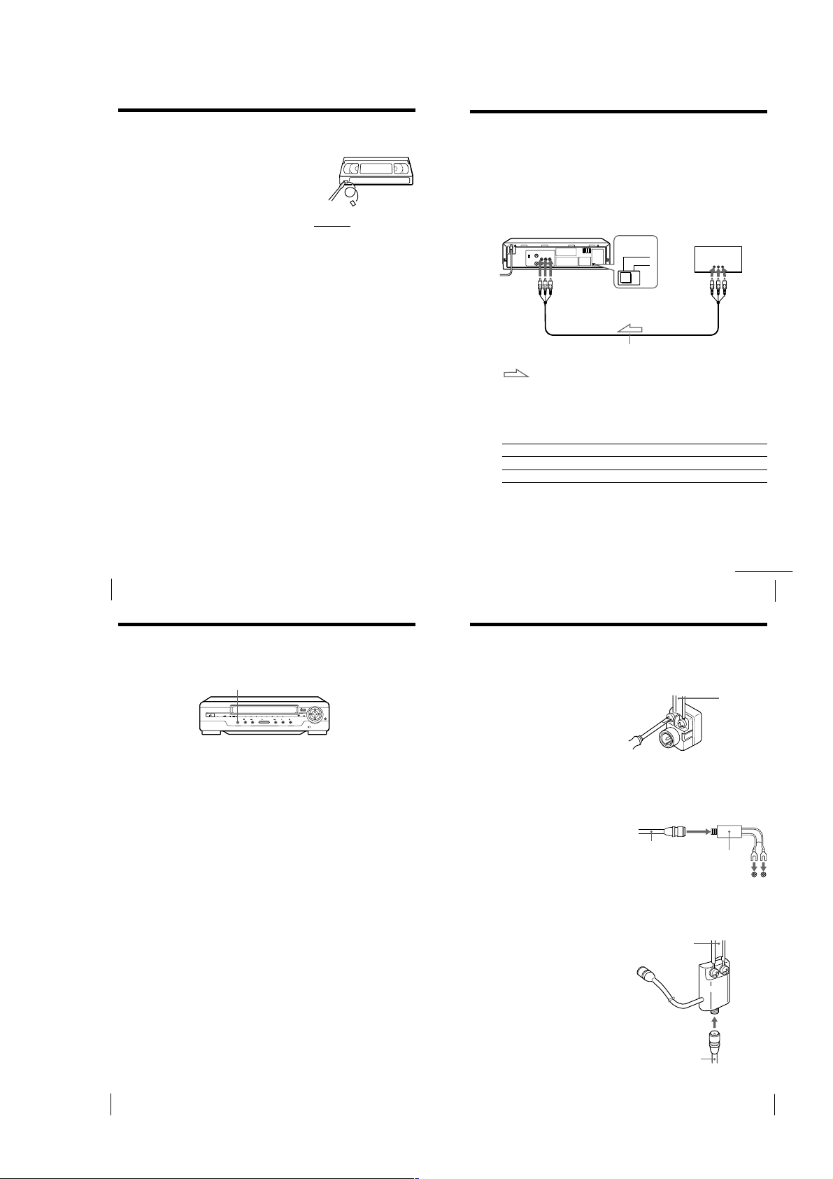
Additional Information
General setup
information
Attaching an external antenna connector
300-ohm to 75-ohm matching transformer
When using a 300-ohm twin lead cable for a
VHF/UHF antenna, use an antenna connector
(not supplied) to connect the antenna to the
unit.
1
Loosen the screws on the
antenna connector.
2
Wind the twin leads around the
screws on the antenna
connector.
3
Retighten the screw.
75-ohm to 300-ohm matching transformer
When using a TV with the 300-ohm VHF
terminal, use this type antenna connector (not
supplied) to connect the 75-ohm coaxial cable
to the TV.
1
Connect the 75-ohm coaxial
cable to the antenna connector.
2
Attach the 300-ohm Y type
terminal to the TV.
Attaching a UHF/VHF band mixer
When using both a 75-ohm coaxial cable and a
300-ohm twin lead cable for a VHF/UHF
antenna, use a VHF/UHF band separator/
mixer (not supplied) to connect the antenna to
the unit.
1
Loosen the screws on the mixer.
2
Wind the twin leads around the
screws on the mixer.
3
Retighten the screws.
4
Connect the 75-ohm coaxial
cable to the mixer.
75-ohm coaxial
cable
to the 300-ohm VHF terminal
on the TV
300-ohm twin
lead cable
75-ohm coaxial
cable
continued
Additional Operations
300-ohm twin
lead cable
Antenna
connector (not
supplied)
Antenna connector
(not supplied)
UHF/VHF
band
separator/
mixer (not
supplied)
21
Additional Operations
22
1-5
Additional Information
23
Troubleshooting
25
Additional Information
RecordingOthers
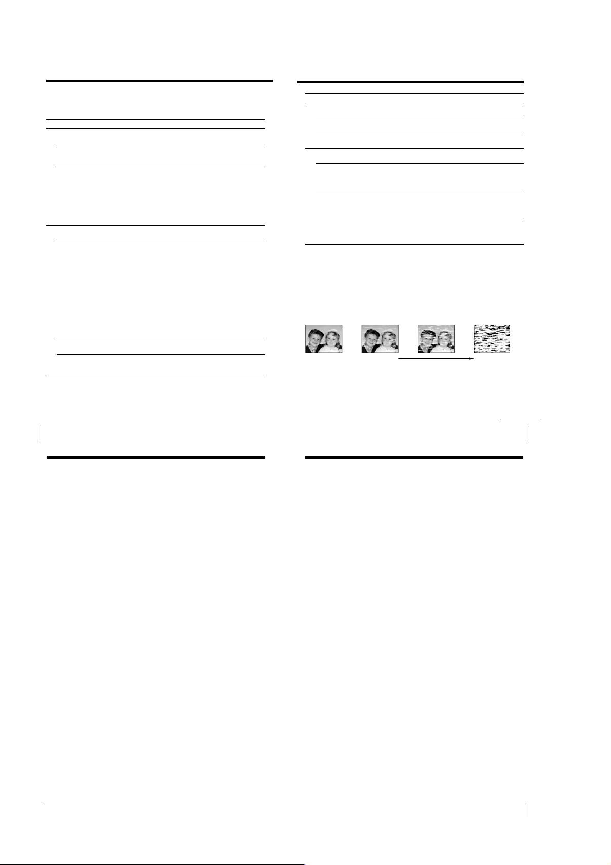
• Normal picture
• Rough picture • Unclear picture • No picture (or
black & white
screen appears)
initial
contamination
terminal
Symptom
The tape starts playing as soon
as it is inserted.
The tape is ejected when you
press r REC.
Nothing happens when you
press r REC.
A tape cannot be inserted.
The remote commander does
not function.
The unit needs to be cleaned.
The indicator lights on the unit
are flashing.
The RESOLUTION CONTROL III
menu appears automatically.
Auto head cleaner
The unit incorporates an auto head cleaner which cleans the video
heads when a tape is loaded or unloaded. When the heads are not
sufficiently clean, even after a tape has been loaded/unloaded several
times, use a video head cleaning cassette.
Symptoms caused by contaminated video heads
Remedy
• The safety tab has been removed. To record on this
tape, cover the tab hole.
• Check that the safety tab has not been removed.
• Make sure the tape is not at its end.
• Check that a tape is not already in the tape
compartment.
• Make sure you are pointing the remote commander at
the remote sensor on the unit.
• Replace all of the batteries in the remote commander
with new ones if they are weak.
• Clean the cabinet, panel, and controls with a dry soft
cloth, or a soft cloth slightly moistened with a mild
detergent solution. Do not use any type of solvent,
such as alcohol or benzine.
• The demonstration mode has been turned on. Cancel
the demonstration mode by pressing STD PICT.
continued
If you have any questions or problems not covered below, please
consult your nearest Sony service facility.
Symptom
The ?/1 POWER switch
does not function.
The power is turned on but the
unit does not operate.
The unit enters standby mode
or turns off automatically.
Power
The playback picture does not
appear on the TV screen.
The picture is not clear.
Playback
The picture rolls vertically
during picture search.
The picture has no sound.
Remedy
• Connect the AC power cord securely.
• Moisture condensation has occured. Turn the power
off, unplug the power cord and leave the unit to dry
for over four hours.
• The auto safety system is triggered to protect your tape
and the unit’s mechanism when there is something
wrong with the tape or when the mechanism is
overloaded. Press ?/1 POWER to restart the unit. If
the unit does not work after pressing ?/1 POWER
again, disconnect the power cord from the wall outlet.
Wait for at least 15 seconds. Then reconnect the power
cord, and press ?/1 POWER again. If the unit still
does not work, please consult your nearest Sony
service facility.
• Make sure the TV is set to the video channel. If you are
using a monitor, set it to video input.
• Adjust the tracking with the V/v TRACKING
NORMAL/SLOW/STILL ADJUST buttons.
• The video heads are dirty (see next page). Clean the
video heads using the Sony T-25CLD, T-25CLW or T25CLDR video head cleaning cassette. If these cleaning
cassettes are not available in your area, have the heads
cleaned at your nearest Sony service facility (a
standard service charge will be required). Do not use a
commercially available liquid type cleaning cassette, as
it may damage the video heads.
• If a message appears, this indicates that the Head
Condition Sensor has detected dirty video heads.
Follow the on-screen message. For details about the
Head Condition Sensor, see page 26.
• The video heads may have to be replaced. Consult
your local Sony service facility for more information.
• Adjust the vertical hold control on the TV or monitor.
• The tape is defective.
• If you made A/V connections, check the audio cable
connection.
Additional Information
24
Troubleshooting (continued)
Sapphire tape cleaner
The unit incorporates a sapphire tape cleaner which cleans a video tape when it is
loaded. This cleaner can prevent the video heads from contamination by removing
dust or mold from a tape with its sapphire edge.
Head condition sensor
The Head Condition Sensor checks the condition of the video heads. If the heads are
dirty, a message will instruct you to insert a video head cleaning cassette. Be sure to
use the Sony T-25CLD, T-25CLW or T-25CLDR video head cleaning cassette. If these
cleaning cassettes are not available in your area, have the head cleaned at your nearest
Sony Service (a standard service charge will be required).
Specifications
System
Format
VHS NTSC standard
Video recording system
Rotary head helical scanning FM system
Video heads
Double azimuth two heads
Video signal
NTSC color, EIA standards
Tape speed
SP: 33.35 mm/s
EP: 11.11 mm/s
Maximum recording/playback time
9 hrs. in EP mode (with T-180 tape)
Fast-forward and rewind time
Approx. 4 min. 30 sec. (with T-120 tape)
Tuner section
RF output channel
VHF channel 3 or 4
Antenna
75-ohm antenna terminal for VHF/UHF
Inputs and outputs
LINE 1 IN
VIDEO IN, phono jack (1)
Input signal: 1 Vp-p, 75 ohms,
unbalanced, sync negative
AUDIO IN, phono jacks (2)
Input level: 327 mVrms
Input impedance: more than 47 kilohms
LINE 1 OUT
VIDEO OUT, phono jack (1)
Output signal: 1 Vp-p, 75 ohms,
unbalanced, sync negative
AUDIO OUT, phono jacks (2)
Standard output: 327 mVrms
Load impedance: 47 kilohms
Output impedance: less than 10 kilohms
General
Power requirements
110 – 240 V AC, 50/60 Hz
Power consumption
12 W
Operating temperature
5°C to 40°C
Storage temperature
–20°C to 60°C
Dimensions
Approx. 355 × 96 × 293 mm (w/h/d)
including projecting parts and controls
Mass
Approx. 3.8 kg
Supplied accessories
Remote commander (1)
R6 (Size AA) batteries (2)
75-ohm coaxial cable with F-type connectors (1)
Audio/video cable (3-phono to 3-phono) (1)
Design and specifications are subject to change
without notice.
Additional Information
26
Additional Information
1-6
27
Index to parts and controls
29
Additional Information
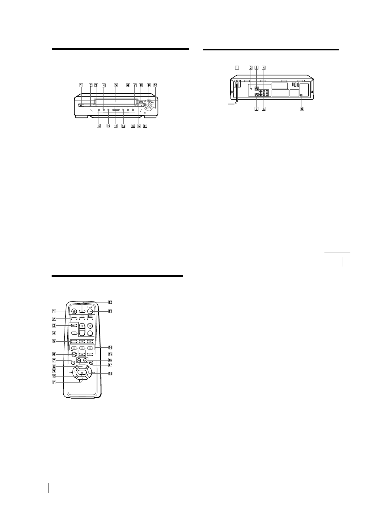
Rear panel
1 AC power cord
2 RF (Radio Frequency) UNIT switch
(9)
3 VHF/UHF IN connector (8)
4 LINE 1 IN AUDIO R/L/VIDEO
jacks (18)
5 CONNECT LINE-1 switch (21)
6 LINE 1 OUT AUDIO R/L/VIDEO
jacks (7)
7 VHF/UHF OUT connector (8)
continued
Refer to the pages indicated in parentheses ( ) for details.
Front panel
1 ?/1 POWER switch/indicator
2 Tape operation indicator
3 HiFi/L/R indicators (12)
4 x STOP button (11)
5 Tape compartment
6 X PAUSE button (11)
7 VIDEO indicator (9)
8 A EJECT button (11)
9 v/V/b/B Resolution Control
buttons (16)
Additional Information
28
Index to parts and controls (continued)
Remote commander
q; STD PICT (standard picture) button
qa TAPE SPEED switch (19)
qs Remote sensor (5)
qd z REC (record) button (19)
qf # M FF (fast-forward) button (11,
qg H PLAY button (10)
qh m3 REW (rewind) button (11, 14)
qj SYNCHRO REC (record) button (22)
1 Z EJECT button (11)
2 TV control buttons (Only for TV) (5)
TV/VIDEO
a (TV power)
?/1 (on/standby)
VOL (volume) +/–
PROG (CH) +/–
3 TV/VIDEO button (9)
4 DISPLAY button (11, 19)
5 TRACKING buttons
AUTO/MANU (17)
V/v NORMAL/SLOW/STILL
ADJUST (17)
6 z REC (record) button (19)
7 AUDIO MONITOR button (12)
8 X PAUSE button (11)
9 m REW (rewind) button (11, 14)
q; H PLAY button (10)
qa x STOP button (11)
qs TRINITRON TV SYNCHRO PLAY
button (13)
qd ?/1 (POWER) switch
qf M/m/</, Resolution Control
buttons (16)
qg STANDARD PICTURE button (16)
qh 3/# SEARCH buttons (14)
qj y SLOW button (14)
qk M FF (fast-forward) button (11, 14)
(16)
14)
Additional Information
30
1-7 E
1-7
SLV-GA35/GA36/GA45/GA55/GA59/GA65/GF85/GF86/SA34
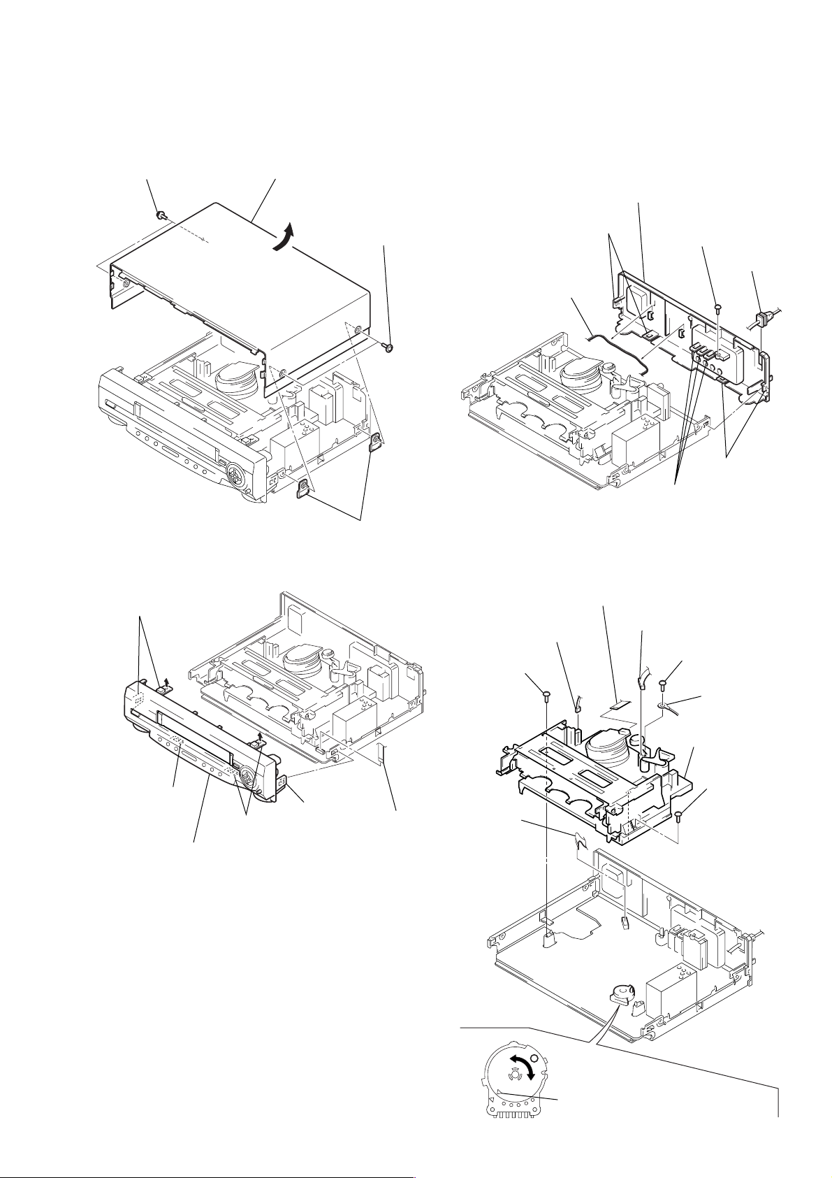
6 Screw
(BVTP3 × 12)
5 Screw
(BVTP3 × 12)
8 Screw
(BVTP3 × 12)
7 Earth lug
4 Flexible
board
(CN201)
9 Mechanism deck
2 Connector
(ACE head)
3 Connector
(FE head)
1 Flat cable
Note: When mounting the mechanism deck,
first align f mark on the rotary switch.
SECTION 2
DISASSEMBLY
Note: Follow the disassembly procedure in the numerical order given.
2-1. UPPER CASE REMOVAL 2-3. REAR PANEL REMOVAL
1 Two U/C screws
3 Upper case
7 Rear panel
2 Two U/C screws
6 Two claws
1 Harness
4 Two U/C insulators
3 Screw
(BVTP3 × 12)
2 Power cord
4 Two claws
5 Three claws
2-2. FRONT PANEL SECTION REMOVAL 2-4. MECHANISM DECK REMOVAL
2 Two claws
3 Claw
6 Front panel section
4 Two claws
5 Claw
1 Flat cable
(CN401)
2-1
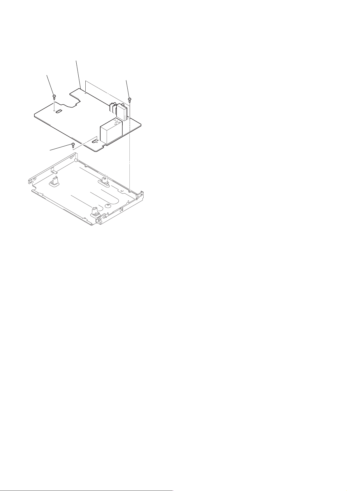
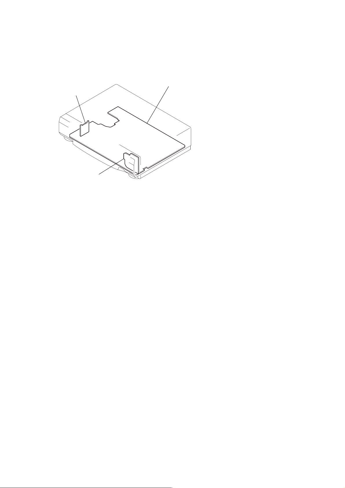
2-5. MA-366 BOARD REMOVAL
4 MA-366 board
2 Screw (B3)
1 Screw
(B3)
3 Two screws
(B3)
2-2
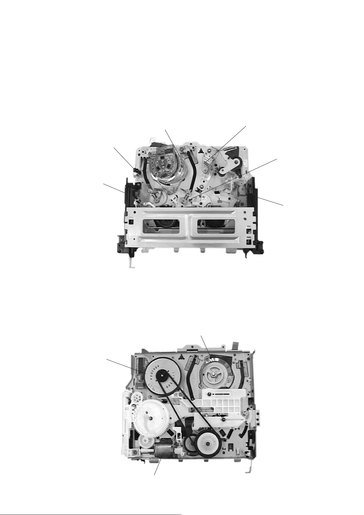
2-6. INTERNAL VIEWS
Drum assembly (M901) (DZH-71E-R)
1-772-147-11 (GA36/GA45: TW/SA34)
Drum assembly (M901) (DZH-89B-R)
1-772-148-11 (GA35/GA45: E, ME, TH/GA55/GA59/GA65)
Drum assembly (M901) (DZH-91B-R)
1-772-149-11 (GF85: TH)
Drum assembly (M901) (DZH-90B-R)
1-772-351-11 (GF85: PL/GF86)
FE head
1-500-144-11
Q002
Tape top sensor
8-729-042-88
ACE head assembly
A-6759-620-A
D001
Tape top/end LED
8-719-048-26
Q001
Tape end sensor
8-729-042-88
Capstan motor
1-698-971-11
Drum assembly (M901) (DZH-71E-R)
1-772-147-11 (GA36/GA45: TW/SA34)
Drum assembly (M901) (DZH-89B-R)
1-772-148-11 (GA35/GA45: E, ME, TH/GA55/GA59/GA65)
Drum assembly (M901) (DZH-91B-R)
1-772-149-11 (GF85: TH)
Drum assembly (M901) (DZH-90B-R)
1-772-351-11 (GF85: PL/GF86)
Cam motor assembly
X-3947-577-1
2-3
2-7. CIRCUIT BOARDS LOCATION
SE-119 (GA59)
(SECAM)
FR-167
(MODE CONTROL)
MA-366
VIDEO, AUDIO,
()
I/O, SERVO/SYSTEM CONTROL
2-42-4 E
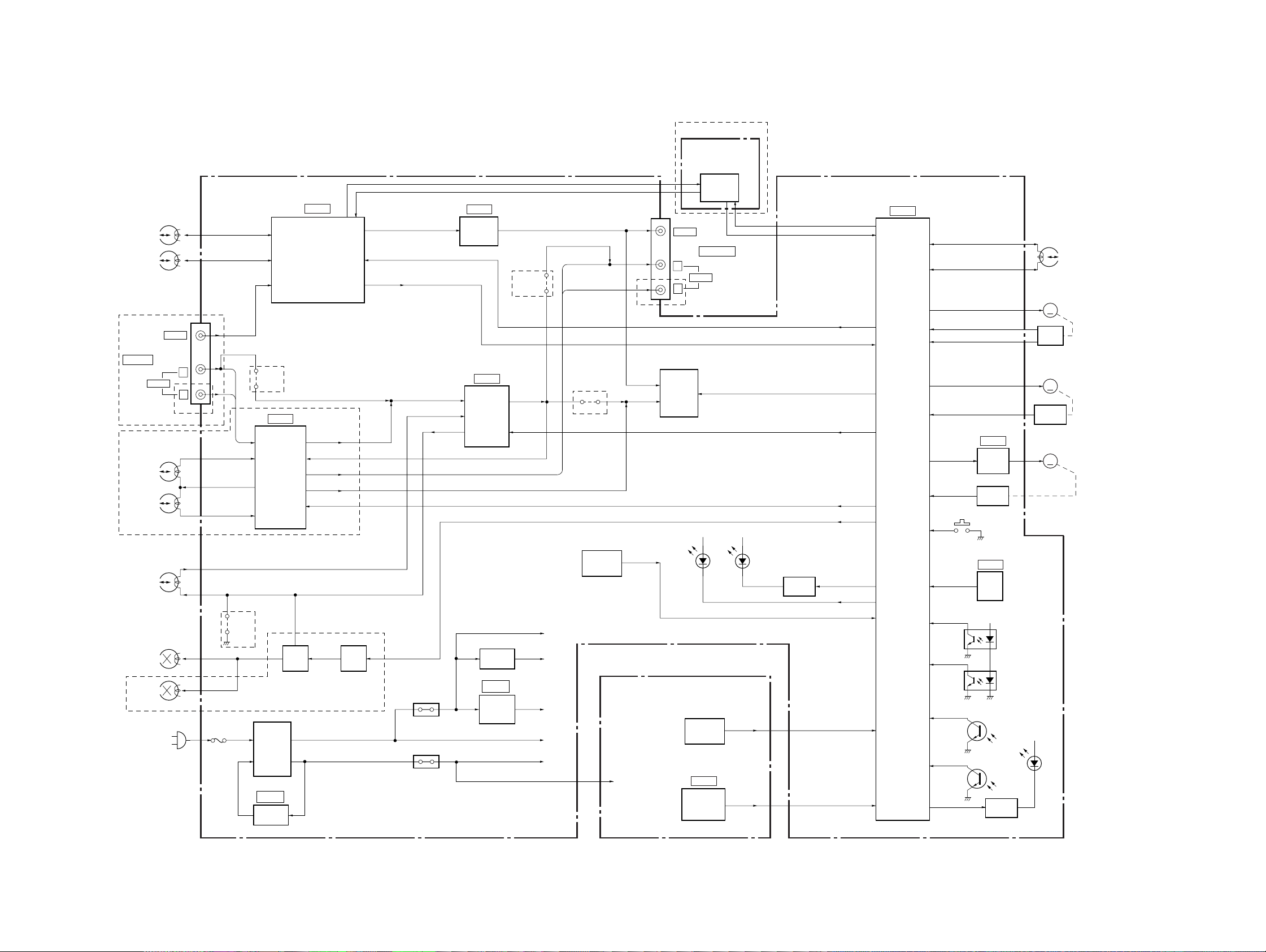
3-1. OVERALL BLOCK DIAGRAM
MA-366 BOARD
(SEE PAGE 4-9 to 4-17)
VIDEO
HEAD
SP
CH1
SP
CH2
EXCEPT GF85/GF86
VIDEO
J901
LINE IN
CH1
CH2
AUDIO
GF85/GF86
AUDIO
HEAD
(HiFi)
L
R
EXCEPT GF85/GF86
JS351
L IN,
R IN
IC301
Hi-Fi
AUDIO
PROCESSOR
SECTION 3
BLOCK DIAGRAMS
IC201
(1/2)
VIDEO OUT
VIDEO REC/PB AMP,
Y/C PROCESSOR
NA OUT
NA IN
L OUT, R OUT
RF OUT
GF85/GF86
RF SWP, V CLOCK, V DATA,
QVD, SHARPNESS
MESECAM, V ENV,
KILL, C SYNC
IC101
(1/2)
OSD
IC201
NORMAL
AUDIO
PROCESSOR
V OUT
(2/2)
EXCEPT
GF85/GF86
JS353
NA OUT
L OUT
R OUT
EXCEPT
GF85/GF86
JS352
MOD V
MOD A
GA59
SE-119 BOARD
(SEE PAGE 4-21)
VIDEO
L
AUDIO
R
GF85/GF86
RFU901
D+5V
IC951
SECAM
PROCESSOR
J901
LINE OUT
D+5V
SLV-GA35/GA36/GA45/GA55/GA59/GA65/GF85/GF86/SA34
SECAM
SECAM DET
RF SWP, V CLOCK, V DATA,
QVD, SHARPNESS
MESECAM, V ENV,
KILL, C SYNC
TV/VTR
A MUTE
S CLK, S DATA
AF SWP, AF ENV
REC P
IC101
SERVO/SYSTEM
CONTROL,
MODE CONTROL
(2/2)
CTL (+)
CTL (–)
DRUM VS
DRUM PG
DRUM FG
CAP VS
CAP FG
CAM
MODE 1-4
IC031
CAM
MOTOR
DRIVER
S102
ROTARY
SWITCH
S101
(REC PROOF)
M901
DRUM
MOTOR
M
PG/FG
PICK UP
M902
CAPSTAN
MOTOR
M
FG
PICK UP
M903
CAM
MOTOR
M
CTL
HEAD
AUDIO
REC/PB
AUDIO
ERASE
FULL
ERASE
(MONO)
FUNCTION
SWITCH
LED
DRIVER
GA35/GA36/SA34
JS371
BIAS
ERASE
OSC
T371, Q372-374
F601
05
T601
POWER
TRANS
IC601
+B ADJ
Q375-377
BIAS
SWITCH
EXCEPT GA35/GA36/SA34
PS601
PS602
Q604
+9V REG
IC103
+5V REG
+12V
+9V
+5V
M+12V
D+5V
FR-167 BOARD
(SEE PAGE 4-20)
D+5V
FUNCTION
SWITCH
IC501
REMOTE
COMMANDER
RECEIVER
KEY 4
KEY 1-3
REMOCON
RESET
T REEL
S REEL
T SENS
Q001
T SENS
S SENS
Q002
S SENS
END LED
IC102
RESET
+12V
T REEL FG
S REEL FG
T/S LED
Q003
LED
DRIVER
PH001
PH002
+12V
D001
3-1 3-2
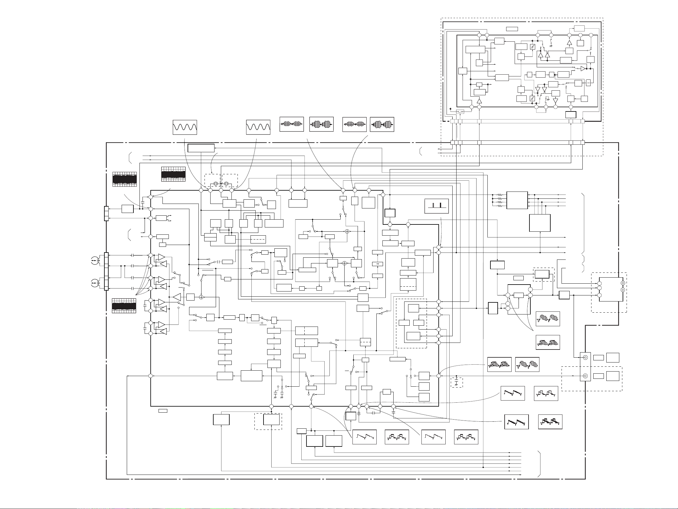
SLV-GA35/GA36/GA45/GA55/GA59/GA65/GF85/GF86/SA34
3-2. VIDEO BLOCK DIAGRAM
IC201ug REC/PB
IC201ua REC/PB
IC201y; REC/PB
IC201y; REC/PB
IC201tk REC/PB
IC201tk REC/PB
GA59
SE-119 BOARD
MODE
CTL
SW5V
Q953
2
6
1
(SEE PAGE 4-21)
27 26
SYNC GATE GEN
/V-SEP
BGP
GEN
AFC
4.43MHz
VCO
B
21
3
Filter Adj
SECAM PROCESSOR
SECAM
DET
to MUTE
to SYNC GATE
to PB/AGC
to REC KILLER
to MUTE
CONTROL
LOGIC
IC951
4.43MHz
OSC
Fo
ADJ
Fo
ADJ
1.1MHz
OSC
21 20 17 16 15
REC
MUTE
B
4.43MHz
BPF-A
4.43MHz
BPF-B
B
PB
MUTE
REC
PB
AGC
AMP
13
BUFFER
Q956
9
REC PB
2.2MHz
X2
BPF
CA VA
PB
REC
8911
VACA
X2
1.1MHz
BPF
BUFFER
REC
PB
SYNC
GATE
Q954
REC
/PB
REC
PB
SYNC
GATE
LIM
1
4
AGC
DET
CN951
5
CH2
CH1
SP
SP
CHECK
2
3
2
1
5
6
05
MA-366 BOARD (1/4)
SERVO/SYSTEM
CONTROL
(SEE PAGE 3-5)
450mVp-p (H) (PAL)
780mVp-p (H) (NTSC)
CN202
PB RF
V SWP
SERVO/SYSTEM
CONTROL
(SEE PAGE 3-5)
CN201
SP CH2
SP COM
SP COM
SP CH1
IC201ih, ij, ik, il REC
IC201ul PB
BUFFER
Q201
1.8Vp-p (H)
V CLOCK
V DATA
RF SWP
V ENV
(SEE PAGE 4-9 to 4-15)
IC201ul PB
320mVp-p (H) (PAL)
580mVp-p (H) (NTSC)
78
79
LOGIC
81
ENV DET
84
HPF
+
86
SP2
–
+
SP2
–
87
+
88
SP1
–
+
SP1
–
89
+
91
EP2
–
+
EP2
–
92
+
93
EP1
–
+
EP1
–
94
97
IC201 (1/2)
VIDEO REC/PB AMP,
Y/C PROCESSOR
520mVp-p (4.43MHz) (PAL)
AFC FILTER SWITCH
HEAD SW1
HEAD SW2
CH2
CH1
CH2
CH1
L-
SW30
SECAM
SP
SW29
SP
REC
VCA
MUTE
SW31
P
R
LC VCO
2FSC
VCO
COLOR KILLER
IO DET
ACC
HPF
SW8
DLIM
DEMO
SUB LPF
MAIN
DE-EMPH
16
PAL
SWITCH
Q203
340mVp-p (H) (PAL)
CTL TRAP
HPF
FH TRAP
R
SW18
TRAP
MIX
LEVEL ADJ
G
EQ
P
SW9
510mVp-p (3.58MHz) (NTSC)
Q202
76 75 73 71 64 63 62 60 58 57
SW7
2EL VCO
L-SECAM
SW27
TRAP
X201
4.43MHz
PB/REC
DISCRI
1/2
SW28
629
GA35/GA45: E, ME, TH/
GA55/GA59/GA65/GF85: TH
EXCEPT GA35: E
X202
3.58MHz
X-TAL
VCO/OSC
REC
REC
AFC
AFCPBAPC
DOWN
CONV
2M LPF
1MHPF
7MHPF
L.P.F.
FM MOD
FO/EEV ADJ
S-DET
NTSC
SWITCH
Q204
LPF
FM AGC
SEP
COMP
P
EQ
CARRIER OFFSET
GA35/GA45: E, ME, TH/GA55/
GA59/GA65/GF85: TH
69
CR DET
2FSC
PHASE VCO
P
R
MMS
DL
MAIN EMPH
W.C/DC
1/2
SW20
SW19
SQPB
SQPB
REC:300mVp-p (H) (NTSC)
PB:290mVp-p (H) (NTSC)
SERIAL CONT
INTERFACE
DL R
DELAY CLPF
4PHASE GEN
EDGE
DO
DELAY
DET
N.L
DE. EMPH
EMPH
FBC/ALC
P
Y-LPF
R
SW11
17
L372,C382,
R381,Q378
L.P.F.
SHARPNESS
500mVp-p (H) (PAL)
VCA
CCD
LPF
SW26
P
R
SW25
SW24
PR
MAIN
CONV1
SW23
P
B.EC.K
R
SW13
N.L
R
SW10
P
18
SHARPNESS
CONT
Q261
CONT
Q263
SW22
R
P
R
SW21
P
DO
REC
CLAMP CLAMP
19 21 23
BUFFER
Q262
REC:400mVp-p (H) (PAL)
CLPF
MAIN
CONV2
P
R
BPF
PULSE
GEN
PICTURE
CONT.
SW14
DO
+
PB:580mVp-p (H) (PAL)
440mVp-p (H) (NTSC)
NTSC/PAL
N-P CONT
OUT
C.K
N P
B.D
DE
N.C
YNR
SERVO/SYSTEM
CONTROL
(SEE PAGE 3-5)
55
BUFFER
Q205
VIDEO AGC
2624
+
52
6dB AMP
CLEAR
SYNC
SQUELCH
FEED BACK
CLAMP
VIDEO ALC
C-CCD Y-CCD
SW16
54
6dB AMP
C-SQUELCH
P
SW17
R
L.P.F.
REC:510mVp-p (H) (NTSC)
PB:560mVp-p (H) (NTSC)
SECAM DET
SYNC. SEP
CLOCK
DRIVER
MODE
CONTROL
CCD
ATT
(-10dB)
ATT
(-10dB)
ATT
(-10dB)
REC:390mVp-p (H) (PAL)
PB:500mVp-p (H) (PAL)
SECAM ON
IC201t; REC/PB
5.0Vp-p (H)
51
50
46
44
42
39
37
35
31
IC201wd REC/PB
C SYNC
SECAM DET
SECAM ON
2
6
1
GA35/GA36/SA34
IC201wd REC/PBIC201qk, ql REC/PB IC201qk, ql REC/PB
REC:480mVp-p (H) (NTSC)
PB:550mVp-p (H) (NTSC)
FSC
3
BUFFER
Q264, 267
43
2fsc
AMP
Q266
IC201ea REC/PB
1.1Vp-p (H) (NTSC)
IC201wa REC/PB
REC:320mVp-p (H) (PAL)
PB:430mVp-p (H) (PAL)
IC201wh REC/PB
REC:500mVp-p (H) (PAL)
PB:600mVp-p (H) (PAL)
CHROMA
CONTROLLER
Q290-293
GA35/GA45: E, ME, TH/
GA55/GA59/GA65/GF85: TH
IC101
OSD
OSD
52
53
IC201ea REC/PB
1.1Vp-p (H) (PAL)
BURST GATE
GENERATOR
Q294-299
SWITCH
Q265
(1/3)
55
45
IC101rd, rg REC/PB
2.2Vp-p (H) (PAL)
IC101rd, rg REC/PB
2.2Vp-p (H) (NTSC)
IC201wa REC/PB
REC:400mVp-p (H) (NTSC)
PB:450mVp-p (H) (NTSC)
IC201wh REC/PB
REC:620mVp-p (H) (NTSC)
PB:690mVp-p (H) (NTSC)
SHARP 2
SHARP 1
REC P
SHARPNESS
PAL
NTSC
MESECAM
SERVO/SYSTEM
CONTROL
(SEE PAGE 3-5)
BUFFER
Q901
PB RF
9
CHROMA 4
CHROMA 3
CHROMA 2
CHROMA 1
KILL
QVD
C SYNC
AUDIO
TV/VTR
PB C
5
CN203
SERVO/SYSTEM
CONTROL
(SEE PAGE 3-5)
AUDIO
(SEE PAGE 3-8)
MODE CONTROL
(SEE PAGE 3-9)
EXCEPT
GA45
4
TV/VTR
2
AUDIO
1
VIDEO
VIDEO
VIDEO
GA35/GA36/SA34
RFU901
J901
LINE
OUT
LINE
IN
IN
OUT
3-3 3-4
 Loading...